JP6580495B2 - Holding jig - Google Patents
Holding jig Download PDFInfo
- Publication number
- JP6580495B2 JP6580495B2 JP2016018427A JP2016018427A JP6580495B2 JP 6580495 B2 JP6580495 B2 JP 6580495B2 JP 2016018427 A JP2016018427 A JP 2016018427A JP 2016018427 A JP2016018427 A JP 2016018427A JP 6580495 B2 JP6580495 B2 JP 6580495B2
- Authority
- JP
- Japan
- Prior art keywords
- aircraft panel
- panel
- holding jig
- gripping portions
- aircraft
- Prior art date
- Legal status (The legal status is an assumption and is not a legal conclusion. Google has not performed a legal analysis and makes no representation as to the accuracy of the status listed.)
- Active
Links
Images


Classifications
-
- B—PERFORMING OPERATIONS; TRANSPORTING
- B64—AIRCRAFT; AVIATION; COSMONAUTICS
- B64F—GROUND OR AIRCRAFT-CARRIER-DECK INSTALLATIONS SPECIALLY ADAPTED FOR USE IN CONNECTION WITH AIRCRAFT; DESIGNING, MANUFACTURING, ASSEMBLING, CLEANING, MAINTAINING OR REPAIRING AIRCRAFT, NOT OTHERWISE PROVIDED FOR; HANDLING, TRANSPORTING, TESTING OR INSPECTING AIRCRAFT COMPONENTS, NOT OTHERWISE PROVIDED FOR
- B64F5/00—Designing, manufacturing, assembling, cleaning, maintaining or repairing aircraft, not otherwise provided for; Handling, transporting, testing or inspecting aircraft components, not otherwise provided for
- B64F5/10—Manufacturing or assembling aircraft, e.g. jigs therefor
-
- B—PERFORMING OPERATIONS; TRANSPORTING
- B21—MECHANICAL METAL-WORKING WITHOUT ESSENTIALLY REMOVING MATERIAL; PUNCHING METAL
- B21J—FORGING; HAMMERING; PRESSING METAL; RIVETING; FORGE FURNACES
- B21J15/00—Riveting
- B21J15/10—Riveting machines
- B21J15/14—Riveting machines specially adapted for riveting specific articles, e.g. brake lining machines
- B21J15/142—Aerospace structures
-
- B—PERFORMING OPERATIONS; TRANSPORTING
- B23—MACHINE TOOLS; METAL-WORKING NOT OTHERWISE PROVIDED FOR
- B23Q—DETAILS, COMPONENTS, OR ACCESSORIES FOR MACHINE TOOLS, e.g. ARRANGEMENTS FOR COPYING OR CONTROLLING; MACHINE TOOLS IN GENERAL CHARACTERISED BY THE CONSTRUCTION OF PARTICULAR DETAILS OR COMPONENTS; COMBINATIONS OR ASSOCIATIONS OF METAL-WORKING MACHINES, NOT DIRECTED TO A PARTICULAR RESULT
- B23Q3/00—Devices holding, supporting, or positioning work or tools, of a kind normally removable from the machine
- B23Q3/02—Devices holding, supporting, or positioning work or tools, of a kind normally removable from the machine for mounting on a work-table, tool-slide, or analogous part
- B23Q3/06—Work-clamping means
- B23Q3/062—Work-clamping means adapted for holding workpieces having a special form or being made from a special material
- B23Q3/065—Work-clamping means adapted for holding workpieces having a special form or being made from a special material for holding workpieces being specially deformable, e.g. made from thin-walled or elastic material
-
- B—PERFORMING OPERATIONS; TRANSPORTING
- B64—AIRCRAFT; AVIATION; COSMONAUTICS
- B64C—AEROPLANES; HELICOPTERS
- B64C1/00—Fuselages; Constructional features common to fuselages, wings, stabilising surfaces or the like
- B64C1/06—Frames; Stringers; Longerons ; Fuselage sections
- B64C1/12—Construction or attachment of skin panels
Description
本発明は、保持治具に関するものである。 The present invention relates to a holding jig.
航空機の胴体パネルは、曲面を有する板状のスキンと、胴体の長手方向に沿ってスキンに設けられる長尺状のストリンガーと、胴体の周方向に沿って設けられるフレームなどが組み合わされて構成される。 An aircraft fuselage panel is configured by combining a plate-like skin having a curved surface, a long stringer provided on the skin along the longitudinal direction of the fuselage, and a frame provided along the circumferential direction of the fuselage. The
隣り合うスキン同士の重なり部分の結合や、スキン又はストリンガーに対するフレームの結合は、位置決め治具を用いて、各部品の位置を正確に決定してから行われている。部品間の結合はリベットが使用される。位置決め治具を用いることにより、剛性が低いスキンに対して正確な位置で各部品を結合できる。 The joining of adjacent skins and the joining of the frame to the skin or stringer are performed after the position of each component is accurately determined using a positioning jig. Rivets are used to connect the parts. By using the positioning jig, each component can be coupled to the skin having low rigidity at an accurate position.
従来、位置決め治具は、工場内の所定位置に固定されて用いられており、上述のスキン同士の結合やフレームの結合は所定位置で行われて胴体パネルが製造されている。製造中の胴体パネルが移動するタイミングは、一の位置決め治具から別の位置決め治具又は一の工程の作業場所から次工程の作業場所へ移動される場合のみに限られており、位置決め治具自体が移動することはなかった。 Conventionally, a positioning jig is used by being fixed at a predetermined position in a factory, and the body panel is manufactured by combining the skins and the frame at the predetermined positions. The timing for moving the body panel during manufacture is limited to the case where the body is moved from one positioning jig to another positioning jig or from the work place of one process to the work place of the next process. It did not move itself.
また、従来の位置決め治具は、胴体パネルのフレームごとに対応した多数の位置決め材が設けられているため、全体の重量が大きく、位置決め治具を搬送するには動力が大きくなるなど不適切であった。また、従来の位置決め治具は、胴体パネルのフレームの間隔に対応して多数の位置決め材が配置されているため、自動打鋲機を適用できる範囲が限られている。そのため、自動打鋲機を用いて締結できるリベット数の全体リベット数における割合が少なかった。 In addition, since the conventional positioning jig is provided with a large number of positioning materials corresponding to each frame of the fuselage panel, the overall weight is large, and it is inappropriate to transfer the positioning jig because the power is large. there were. Further, in the conventional positioning jig, a large number of positioning members are arranged corresponding to the intervals of the frames of the body panel, so that the range in which the automatic striking machine can be applied is limited. Therefore, the ratio of the number of rivets that can be fastened using an automatic hammering machine to the total number of rivets was small.
本発明は、このような事情に鑑みてなされたものであって、航空機パネルの形状を保持する保持治具について簡素化した構造とし、適切な形状で航空機パネルを保持することが可能な保持治具を提供することを目的とする。 The present invention has been made in view of such circumstances, and has a simplified structure with respect to a holding jig for holding the shape of an aircraft panel, and is capable of holding the aircraft panel in an appropriate shape. The purpose is to provide ingredients.
上記課題を解決するために、本発明の保持治具は以下の手段を採用する。
すなわち、本発明に係る保持治具は、一軸方向に対して延在する直線状の水平材を有する枠材と、板状部材を有する航空機パネルの対向する2辺の端部を把持する複数の把持部と、前記複数の把持部によって把持される前記航空機パネルに対応して前記水平材とは別に設けられ、前記複数の把持部を一体的に支持する支持体とを備え、前記複数の把持部によって、前記航空機パネルの端部が把持されつつ、前記一軸方向に対して垂直方向に切断した断面が曲線形状となるように前記航空機パネルが保持され、前記航空機パネルを保持した状態で搬送され得る構成を有する。
In order to solve the above problems, the holding jig of the present invention employs the following means.
That is, the holding jig according to the present invention includes a frame member having a linear horizontal member extending in a uniaxial direction, and a plurality of opposite end portions of an aircraft panel having a plate member. A plurality of grips, comprising: a gripper; and a support member provided separately from the horizontal member corresponding to the aircraft panel gripped by the plurality of grippers and integrally supporting the plurality of grippers. the parts, while the end of the aircraft panel is grasped, a cross section cut in a direction perpendicular to the uniaxial direction is the aircraft panel is held to be a curved shape, it is conveyed in a state of holding the aircraft panel Having a configuration to obtain.
この構成によれば、板状部材を有する航空機パネルは、複数の把持部によって、航空機パネルの対向する2辺の端部が把持され、複数の把持部は、航空機パネルに対応して設けられる支持体によって一体的に支持される。このとき、航空機パネルは、一軸方向に対して垂直方向に切断した断面が曲線形状となるように保持される。航空機パネルは、航空機パネルの2辺の端部で把持されて形状が保持されることから、保持治具は、簡素な構造で航空機パネルを保持できる。また、保持治具は、航空機パネルを保持した状態で搬送され得る構成を有することから、航空機パネルは、形状を保持した状態で搬送される。なお、一軸方向とは、例えば航空機パネルの長手方向であり、航空機パネルが胴体パネルである場合、航空機の機軸方向である。 According to this configuration, the aircraft panel having a plate-like member is gripped at the two opposite ends of the aircraft panel by the plurality of gripping portions, and the plurality of gripping portions are provided corresponding to the aircraft panel. It is supported integrally by the body. At this time, the aircraft panel is held such that a cross section cut in a direction perpendicular to the uniaxial direction has a curved shape. Since the aircraft panel is gripped and held at the ends of the two sides of the aircraft panel, the holding jig can hold the aircraft panel with a simple structure. Further, since the holding jig has a configuration that can be transported while holding the aircraft panel, the aircraft panel is transported while maintaining its shape. The uniaxial direction is, for example, the longitudinal direction of the aircraft panel, and when the aircraft panel is a fuselage panel, it is the aircraft axis direction.
上記発明において、前記支持体は、前記一軸方向に沿って、前記航空機パネルの対向する2辺の各辺に対応して1本ずつ設けられる第1支持材を有し、前記第1支持材に支持された前記複数の把持部は、前記一軸方向に沿った前記航空機パネルの対向する2辺の端部で前記航空機パネルを把持する。 In the above invention, the support body has a first support member provided one by one corresponding to each of two opposing sides of the aircraft panel along the uniaxial direction. The plurality of supported gripping units grip the aircraft panel at two opposite ends of the aircraft panel along the uniaxial direction.
この構成によれば、第1支持材は、一軸方向に沿って、例えば一軸方向に対して平行又は斜め方向に1本ずつ設けられ、その第1支持材は、航空機パネルの対向する2辺の各辺に対応して設けられている。そして、複数の把持部は、第1支持材に支持されており、航空機パネルは、第1支持材に支持された複数の把持部によって、航空機パネルの対向する2辺で把持される。 According to this configuration, the first support member is provided one by one along the uniaxial direction, for example, in parallel or obliquely with respect to the uniaxial direction, and the first support member is provided on the two opposite sides of the aircraft panel. It is provided corresponding to each side. The plurality of gripping portions are supported by the first support member, and the aircraft panel is gripped on the two opposite sides of the aircraft panel by the plurality of gripping portions supported by the first support member.
上記発明において、前記第1支持材が固定される位置が、前記航空機パネルの形状に応じて、前記航空機パネルの前記一軸を中心とした周方向に変更可能である。 In the above invention, the position where the first support member is fixed can be changed in the circumferential direction around the one axis of the aircraft panel according to the shape of the aircraft panel.
この構成によれば、第1支持材が固定される位置は、航空機パネルの形状に応じて変更可能であることから、航空機パネルのサイズが異なる場合も、複数の把持部の位置が変更されるため、複数の把持部が航空機パネルを把持できる。 According to this configuration, since the position where the first support member is fixed can be changed according to the shape of the aircraft panel, the positions of the plurality of gripping portions are changed even when the size of the aircraft panel is different. Therefore, a plurality of gripping units can grip the aircraft panel.
上記発明において、前記支持体は、前記一軸方向に対して垂直方向の面内に、前記航空機パネルの対向する2辺の各辺の曲線形状に対応して1本ずつ設けられる第2支持材を有し、前記第2支持材は、前記一軸を中心にして周方向に沿った前記航空機パネルの対向する2辺の端部で前記航空機パネルを載置する。 In the above invention, the support is provided with a second support member provided in a plane perpendicular to the uniaxial direction, corresponding to the curved shape of each of the two opposing sides of the aircraft panel. And the second support member mounts the aircraft panel at two opposite end portions of the aircraft panel along a circumferential direction around the one axis.
この構成によれば、第2支持材は、一軸方向に対して垂直方向の面内に1本ずつ設けられ、その第2支持材は、一軸を中心にして周方向に沿った航空機パネルの対向する2辺の各辺の曲線形状に対応して設けられている。そして、複数の把持部は、第2支持材に支持されており、航空機パネルは、第2支持材に支持された複数の把持部によって、航空機パネルの対向する2辺で把持される。 According to this configuration, the second support members are provided one by one in a plane perpendicular to the uniaxial direction, and the second support member is opposed to the aircraft panel along the circumferential direction around the uniaxial direction. Are provided corresponding to the curved shape of each of the two sides. The plurality of gripping portions are supported by the second support member, and the aircraft panel is gripped on the two opposite sides of the aircraft panel by the plurality of gripping portions supported by the second support member.
上記発明において、前記支持体は、前記一軸方向に対して垂直方向の面内に、前記航空機パネルの対向する2辺の各辺の曲線形状に対応して1本ずつ設けられる第2支持材を有し、前記第2支持材に支持された前記複数の把持部は、前記一軸を中心にして周方向に沿った前記航空機パネルの対向する2辺で前記航空機パネルを把持する。 In the above invention, the support is provided with a second support member provided in a plane perpendicular to the uniaxial direction, corresponding to the curved shape of each of the two opposing sides of the aircraft panel. The plurality of gripping portions supported by the second support member grip the aircraft panel at two opposing sides of the aircraft panel along a circumferential direction around the one axis.
この構成によれば、第2支持材は、一軸方向に対して垂直方向の面内に1本ずつ設けられ、その第2支持材は、一軸を中心にして周方向に沿った航空機パネルの対向する2辺の各辺の曲線形状に対応して設けられている。そして、複数の把持部は、第2支持材に支持されており、航空機パネルは、第2支持材に支持された複数の把持部によって、航空機パネルの対向する2辺で把持される。 According to this configuration, the second support members are provided one by one in a plane perpendicular to the uniaxial direction, and the second support member is opposed to the aircraft panel along the circumferential direction around the uniaxial direction. Are provided corresponding to the curved shape of each of the two sides. The plurality of gripping portions are supported by the second support member, and the aircraft panel is gripped on the two opposite sides of the aircraft panel by the plurality of gripping portions supported by the second support member.
上記発明において、前記第2支持材が固定される位置が、前記航空機パネルの形状に応じて、前記一軸方向に沿って変更可能である。
この構成によれば、第2支持材が固定される位置は、航空機パネルの形状に応じて一軸方向に沿って変更可能であることから、航空機パネルの一軸方向のサイズが異なる場合も、複数の把持部が航空機パネルを把持できる。
In the above invention, the position where the second support member is fixed can be changed along the uniaxial direction according to the shape of the aircraft panel.
According to this configuration, the position where the second support member is fixed can be changed along the uniaxial direction according to the shape of the aircraft panel. The gripping part can grip the aircraft panel.
上記発明において、前記航空機パネルの前記板状部材が切欠き部を有し、前記切欠き部の端部を把持する複数の第2の把持部と、前記複数の第2の把持部によって把持される前記切欠き部の端部に対応して設けられ、前記複数の第2の把持部を支持する第2の支持体とを更に備える。 In the above invention, the plate-like member of the aircraft panel has a notch, and is gripped by a plurality of second grips that grip an end of the notch, and the plurality of second grips. And a second support that is provided corresponding to an end of the notch and supports the plurality of second grips.
この構成によれば、板状部材において切欠き部を有する航空機パネルは、複数の第2の把持部によって、航空機パネルの切欠き部の端部が把持され、複数の第2の把持部は、切欠き部に対応して設けられる第2の支持体によって支持される。これにより、切欠き部の周辺における板状部材の変形量を低減できる。 According to this configuration, the aircraft panel having a notch portion in the plate-like member is gripped at the end of the notch portion of the aircraft panel by the plurality of second gripping portions, and the plurality of second gripping portions are: It is supported by the 2nd support body provided corresponding to a notch part. Thereby, the deformation amount of the plate-shaped member around the notch can be reduced.
上記発明において、前記把持部は、トグル機構を用いたトグルクランプであり、前記航空機パネルを押し付けるロッド状の押し付け部と、前記押し付け部を移動させる駆動部と、を有する。
この構成によれば、把持部がトグルクランプを用いて構成されており、駆動部がロッド状の押し付け部を移動させて、押し付け部が航空機パネルを押し付けることによって、把持部が航空機パネルを把持する。
In the above invention, the gripping part is a toggle clamp using a toggle mechanism, and includes a rod-shaped pressing part that presses the aircraft panel and a driving part that moves the pressing part.
According to this configuration, the gripping unit is configured using a toggle clamp, and the gripping unit grips the aircraft panel by the drive unit moving the rod-shaped pressing unit and the pressing unit pressing the aircraft panel. .
本発明によれば、航空機パネルを航空機パネルの対向する2辺の端部で把持し、航空機パネルが支持体に対し一体的に保持されることから、航空機パネルを保持する保持治具について簡素化した構造とし、適切な形状で航空機パネルを保持することができる。 According to the present invention, since the aircraft panel is gripped by the two opposite ends of the aircraft panel and the aircraft panel is integrally held with respect to the support, the holding jig for holding the aircraft panel is simplified. The aircraft panel can be held in an appropriate shape.
以下に、本発明に係る実施形態について、図面を参照して説明する。
[第1実施形態]
本発明の第1実施形態に係る保持治具1は、例えば、リベットによって、航空機パネルを構成するスキン同士を重ね合わせて結合する際や、リベットによって、スキン又はストリンガーに対しフレームを結合する際に、航空機パネルの形状を所定の形状に保持するために用いられる。
Embodiments according to the present invention will be described below with reference to the drawings.
[First Embodiment]
The holding
なお、以下では、航空機の胴体パネル10を製造する方法について説明するが、本発明はこの例に限定されない。例えば、胴体パネル10以外の翼などの航空機部材を製造する方法にも適用できる。
In the following, a method for manufacturing an
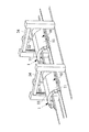
航空機の胴体パネル10は、図1に示すように、曲面を有する板状のスキン11と、胴体の一軸方向、すなわち航空機の機軸方向(長手方向)に沿ってスキン11に設けられる長尺状のストリンガー12と、胴体の周方向に沿って設けられるフレーム(図示せず。)などが組み合わされて構成される。胴体パネル10は、例えばアルミニウム製又はアルミニウム合金製であり、サイズの一例は、長手方向長さが10m、弦長さが6mであり、板厚が2mmから5mmである。
As shown in FIG. 1, an
本実施形態に係る保持治具1が胴体パネル10を保持する工程において、胴体パネル10は、航空機の略円筒形状の胴体部分が、機軸方向及び周方向に分割された形状である。したがって、胴体パネル10は、機軸方向に対して垂直方向の断面が円弧形状を有する。胴体パネル10において、機軸方向に対して平行又は斜めの対向する2辺は、保持治具1によって胴体パネル10が保持されたとき、胴体パネル10の下端に位置する。また、胴体パネル10において、機軸方向に対し垂直な面に収まる対向する2辺は、円弧形状であり、保持治具1によって胴体パネル10が保持されたとき、胴体パネル10の側端に位置する。
In the process of holding the
保持治具1は、搬送可能な構成を有しており、例えば、チェーンコンベヤ、ベルトコンベヤ等の搬送装置(図示せず。)に載置されて、一端側から他端側へ搬送される。搬送装置は、チェーン又はベルト等がモーターによって駆動され、チェーン又はベルト等は、保持治具1の水平材6に対して平行に巻かれて設けられる。保持治具1は、例えば、アルミニウム製又はアルミニウム合金製である。図1では、保持治具1は、固定台60に固定されている状態を示している。
The holding
保持治具1では、複数の把持部3は、支持体5によって支持され、相対位置が固定されて一体化されており、2本の水平材6の底部が同一面内に収まる形状を有する。これにより、保持治具1は、搬送装置によって搬送可能である。
In the holding
保持治具1が、搬送装置によって移動されている間は、胴体パネル10に対しリベット締結作業は行われず、保持治具1が1箇所に固定された状態で、胴体パネル10に対しリベット締結作業が行われる。例えば、自動打鋲機が所定の場所に置かれており、その自動打鋲機によるリベット締結が完了すると、搬送装置によって、保持治具1は他の場所へ搬送される。搬送された場所では、他の自動打鋲機が置かれており、他の自動打鋲機によるリベット締結が行われる。または、搬送された場所では、作業員による作業場所となっており、手作業によるリベット締結又は検査等が行われる。
While the holding
本実施形態に係る保持治具1は、図1及び図2に示すように、枠材4と、支持体5と、把持部3などを備える。保持治具1に胴体パネル10が保持されるとき、胴体パネル10は、上側に凸となるように保持される。
As shown in FIGS. 1 and 2, the holding
枠材4は、一方向に延在する直線状の2本の水平材6と、2本の水平材6間に設置され、アーチ状に形成された2本のアーチ材7などからなる。枠材4の水平材6及びアーチ材7は、後述する支持体5を支持する。
The frame member 4 is composed of two straight
水平材6は、保持治具1に設置される胴体パネル10の機軸方向に沿って、例えば、胴体パネル10の機軸方向に対して平行に配置される。水平材6の一端部と他端部には、アーチ材7の下端が結合して設けられる。これにより、保持治具1は、2本の水平材6と2本のアーチ材7とによって、ほぼ鞍形の形状を有する。
The
なお、本実施形態の保持治具1では、2本の水平材6の一端部同士又は他端部同士を結合し、水平材6に対し垂直方向に延在する桁材は、設けられない。これにより、保持治具1に胴体パネル10が設けられた場合において、胴体パネル10の下部で、桁材に妨害されることなく、機軸方向に沿って通過可能な作業空間を確保できる。
In the holding
水平材6の長さは、リベット締結によって製造される胴体パネル10の機軸方向の長さよりも長く、2本の水平材6の配置間隔は、リベット締結によって製造される胴体パネル10の弦長さよりも長い。
The length of the
アーチ材7は、曲線形状を有する枠材4であり、保持治具1に設置される胴体パネル10の機軸方向に対して垂直方向の面内に配置される。アーチ材7は、水平材6の一端側と他端側にそれぞれ一つずつ設けられ、2本の水平材6と結合される。これにより、枠材4は、水平材6とアーチ材7が一体化した構成を有する。アーチ材7の曲線形状、例えば曲率は、製造する胴体パネル10の曲率にほぼ対応して設けられる。
The
支持体5は、機軸方向に延在する直線状の2本の下端支持材8と、2本の下端支持材8間に設置され、アーチ状に形成された2本の側端支持材9などからなる。
The
下端支持材8は、把持部3を介して、胴体パネル10の下端を支持する。下端支持材8は、枠材4の水平材6よりも上方に位置し、保持治具1に設置される胴体パネル10の機軸方向に沿って、例えば、胴体パネル10の機軸方向に対して平行又は斜め方向になるように配置される。下端支持材8は、保持治具1に設置される胴体パネル10の対向する2辺の各辺に対応して配置される。例えば、下端支持材8は、胴体パネル10の直線状の対向する2辺の端部に沿うように配置される。
The lower
例えば、製造する胴体パネル10が、機軸方向に沿って曲率が全て同じである単曲面である場合、胴体パネル10の機軸が水平面に対して平行になるように、胴体パネル10が保持治具1に設置されたとき、下端支持材8と水平材6の延在方向は平行である。一方、製造する胴体パネル10が、機軸方向に沿って曲率が変化する複曲面である場合、胴体パネル10の機軸が水平面に対して平行になるように、胴体パネル10が保持治具1に設置されたとき、下端支持材8の延在方向は、水平材6の延在方向に対し斜めである。
For example, when the
また、製造する胴体パネル10が、複曲面である場合、胴体パネル10の機軸を水平面に対して斜めにして、保持治具1上における胴体パネル10の最上部が機軸方向に沿って水平面に対してほぼ平行になるように、胴体パネル10が保持治具1に設置されてもよい。すなわち、胴体パネル10の横断面のうち半径の小さい側の中心が、半径の大きい側の中心よりも高くなるように、胴体パネル10が保持治具1に設置される。これにより、門型自動打鋲機32(図5参照)から胴体パネル10までの距離が、胴体パネル10の機軸方向でほぼ等しくなる。
Moreover, when the
下端支持材8は、例えば、水平材6との間に設けられた補助材21を介して、水平材6によって支持される。補助材21は、一端部が水平材6と連結し、他端部が下端支持材8と連結する部材であり、水平材6及び下端支持材8の長手方向に沿って複数本が配置される。
The lower
下端支持材8には、複数の把持部3が互いに間隔を空けて配置される。下端支持材8の長さは、製造する胴体パネル10の機軸方向の長さよりも長く、2本の下端支持材8の配置間隔は、製造する胴体パネル10の弦長長さよりも長い。また、把持部3が胴体パネル10の下端部を下方から支持するように、下端支持材8は、保持される胴体パネル10よりも下方に位置する。
下端支持材8の長手方向の一端部と他端部には、側端支持材9の下端が結合して設けられる。
A plurality of
A lower end of the side
側端支持材9は、把持部3を介して胴体パネル10の側端を支持する。側端支持材9は、曲線形状を有する部材であり、保持治具1に設置される胴体パネル10の機軸方向に対して垂直方向の面内に配置される。側端支持材9は、保持治具1に設置される胴体パネル10の対向する2辺の各辺に対応して配置される。
The side
側端支持材9は、下端支持材8の長手方向の一端側と他端側にそれぞれ一つずつ設けられ、2本の下端支持材8と結合される。これにより、支持体5は、下端支持材8と側端支持材9が一体化した構成を有する。側端支持材9の曲線形状、例えば曲率は、製造する胴体パネル10の曲率に対応して設けられる。側端支持材9には、上述した把持部3と同様の構成を有する把持部3が複数設けられて、把持部3が胴体パネル10の側端を把持して支持してもよい。
One side
このとき、側端支持材9に設けられる複数の把持部3は、製造する胴体パネル10の曲率に対応する位置に、互いに間隔を空けて設けられる。したがって、複数の把持部3が胴体パネル10を把持することで、把持部3によって把持された胴体パネル10は、製造する胴体パネル10の曲率となるように保持される。
At this time, the plurality of
例えば、製造する胴体パネル10が、機軸方向に沿って曲率が全て同じである単曲面である場合、一端側の側端支持材9における把持部3を結ぶ曲率と、他端側の側端支持材9における把持部3を結ぶ曲率は同じである。一方、製造する胴体パネル10が、一軸方向に沿って曲率が変化する複曲面である場合、一端側の側端支持材9における把持部3を結ぶ曲率は、他端側の側端支持材9における把持部3を結ぶ曲率よりも大きくなる。
For example, when the
なお、上述した説明において、下端支持材8と側端支持材9は、枠材4に対して固定されており、保持治具1が保持する胴体パネル10は予め決められたサイズのものである。但し、本発明は、この例に限定されず、下端支持材8と側端支持材9の少なくともいずれか一方が移動可能な構成を有してもよい。
In the above description, the lower
例えば、図3に示すように、側端支持材9が固定される位置が、保持される胴体パネル10の形状に応じて、胴体パネル10の機軸方向に沿って変更可能でもよい。例えば、図3(a)に示すように、側端支持材9が保持治具1の機軸方向の中間側に位置したり、図3(b)に示すように、側端支持材9が保持治具1の機軸方向の端部側に位置したりする。これにより、胴体パネル10の機軸方向の長さが異なる場合も、側端支持材9の位置が変更されるため、側端支持材9が胴体パネル10を載せることができ、一つの保持治具1が複数種類の航空機パネルを載置できる。
For example, as shown in FIG. 3, the position at which the side
また、下端支持材8が固定される位置が、保持される胴体パネル10の形状に応じて、胴体パネル10の周方向に変更可能でもよい。これにより、胴体パネル10の弦長さが異なる場合も、複数の把持部3の位置が変更されるため、複数の把持部3が胴体パネル10を把持でき、一つの保持治具1が複数種類の航空機パネルを把持できる。
Further, the position where the lower
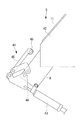
把持部3は、スキン11を有する胴体パネル10の端部を把持する構成を有し、互いに所定間隔を空けて複数個設けられる。把持部3は、下端支持材8又は側端支持材9によって支持される。把持部3は、図7及び図8に示すように、例えばトグルクランプ41と、受け部42などを有する。トグルクランプ41は、トグル機構を用いたクランプであり、下端支持材8又は側端支持材9に固定されたシリンダ43と、シリンダ43に設けられたシリンダロッド44よって移動するロッド状の押し付け部45などからなる。シリンダ43は、駆動部の一例である。
The
押し付け部45の先端には、ローラ46が設けられる。ローラ46は、押し付け部45の移動方向に対して垂直方向を回転軸として回転可能である。これにより、図8に示すように、把持部3が胴体パネル10を把持する際に押し付け部45が胴体パネル10に接触するとき、胴体パネル10の面内方向に作用する力が、胴体パネル10の厚さ方向の力に変換される。その結果、胴体パネル10の変形を抑制できる。
A
図8に示すように、シリンダロッド44がシリンダ43の本体内から伸長したとき、押し付け部45が胴体パネル10のうちスキン11の一面側(外面側)からスキン11の端部を押し付ける。スキン11の他面側(内面側)には、押し付け部45による押圧力を受ける受け部42が設けられる。受け部42は、例えば下端支持材8に固定される。
As shown in FIG. 8, when the
反対に、図7に示すように、シリンダロッド44がシリンダ43の本体内に収容されたとき、押し付け部45がスキン11から離隔する。このとき、押し付け部45は、胴体パネル10を保持治具1に載せたり、保持治具1から外したりするため、胴体パネル10と干渉しない位置に退避する。シリンダ43は、コンプレッサと接続されており、シリンダロッド44に接続されたピストンは、例えば空気圧によって駆動する。
On the contrary, as shown in FIG. 7, when the
把持部3の設置数や、スキン11に対する把持力は、リベット締結作業時に、胴体パネル10がずれたり、振動したりしないように、シミュレーションや実証試験によって決定される。
The number of
上述した本実施形態に係る保持治具1に胴体パネル10を保持する場合、まず、図4に示すように、分割パネル取付けロボット31等によって分割パネル13を持ち上げ、何も載置されていない空の保持治具1に対して、分割パネル13を保持治具1の側端支持材9の所定位置に載置する。分割パネル13とは、胴体パネル10がリベットによって締結される前の部材であり、胴体パネル10が複数に分割された部材である。分割パネル13は、例えば機軸方向に対して平行方向に長く、胴体パネル10の周方向に複数に分割された部材である。分割パネル13は、胴体パネル10が例えば周方向に四つに分割されたものである。
When the
複数の分割パネル13は、保持治具1に載置されたとき、保持治具1上で隣り合う分割パネル13のスキン11同士が重ね合わされる。すなわち、一つの分割パネル13のスキン11の端部の上に、他の分割パネル13のスキン11の端部が載置される。そして、スキン11同士は、重なり合う部分が、リベットで仮留めされる。
When the plurality of divided
そして、仮留めされた胴体パネル10は、下端支持材8に設けられた把持部3によって固定される。なお、このとき、胴体パネル10の形状を保持するため、保持治具1以外の初期形状保持治具(図示せず。)を用いて、胴体パネル10を下側から保持するようにしてもよい。
Then, the temporarily fastened
仮留めされ、把持部3によって固定された胴体パネル10は、保持治具1に設置された状態で次工程に移動される。保持治具1の移動は、例えば、保持治具1の底部に位置するコンベヤによって行われる。初期形状保持治具を用いた場合は、保持治具1を移動する際、初期形状保持治具が胴体パネル10から外される。本実施形態によれば、この状態でも、完成された胴体パネル10の形状が保持されるように、保持治具1は、胴体パネル10を保持している。
The
移動された保持治具1上の胴体パネル10は、例えば、自動打鋲機又は作業員の手作業によるリベットの締結が行われる。
The
保持治具1上に載置された胴体パネル10に対するリベットの締結作業としては、図5に示すように、隣り合うスキン11同士の重なり合う部分を、自動打鋲機(例えば、門型フレーム34を備える門型自動打鋲機32)で締結する作業や、図6に示すように、フレーム70が胴体パネル10の内面側、すなわち、保持治具1で支持されている胴体パネル10のスキン11の下側の面やストリンガー12に、取付用ロボット35によって仮留めされた後、スキン11の下側の面やストリンガー12に対して、フレーム70を自動打鋲機33で締結する作業がある。また、それ以外に、胴体パネル10に取り付けられる航空機ドアのヒンジ取り付け、配線配管用ブラケット又はセンサ設置用ブラケットの取り付けが、手作業によるリベット締結作業によって行われる。
As shown in FIG. 5, the rivet is fastened to the
リベット締結が完了した胴体パネル10は、保持治具1に設置された状態で次工程に移動される。リベット締結完了後は、検査又は検査結果に基づく手直しが行われる。検査や手直しが完了した胴体パネル10は、本実施形態に係る保持治具1から、クレーン等によって吊り上げられて取り外される。その後、胴体パネル10は、他の治具に載置されて、塗装などが行われる。
After the rivet fastening is completed, the
以上、本実施形態に係る保持治具1は、胴体パネル10の端部で胴体パネル10を支持する。すなわち、スキン11を有する胴体パネル10は、複数の把持部3によって、胴体パネル10の対向する2辺(例えば、機軸方向に対して平行な対向する2辺)の端部が把持される。このとき、複数の把持部3は、胴体パネル10に対応して設けられる支持体5を介して一体的に支持されている。
As described above, the holding
また、胴体パネル10は、機軸方向に対して垂直方向に切断した断面が曲線形状となり、上側が凸となるように保持される。胴体パネル10は、胴体パネル10の2辺の端部で、例えば、胴体パネル10の下側から保持されることから、保持治具1は、簡素な構造で胴体パネル10を保持できる。また、保持治具1は胴体パネル10を保持した状態で搬送され得る構成、例えば、枠材4及び支持体5が一体化されており、水平材6の底部が同一面内に収まる形状を有していることから、保持治具1は、胴体パネル10を保持した状態で搬送できる。
In addition, the
本実施形態の保持治具1は、胴体パネル10の端部で胴体パネル10を支持する構造を有していることによって、従来の治具のように、胴体パネル10に設置される複数のフレーム毎に対応して複数の位置決め材が設けられている治具に比べて、簡素化かつ軽量化されている。したがって、保持治具1に対して胴体パネル10を保持した状態で、胴体パネル10は、保持治具1と共に移動可能である。その結果、保持治具1が異なる作業場所を移動しながら、胴体パネル10に対して、自動打鋲機によるリベットの締結作業を行ったり、手作業によるリベットの締結作業を行ったり、検査・手直し作業を行ったりすることができる。
The holding
[第2実施形態]
次に、図9を参照して、本発明の第2実施形態に係る保持治具について説明する。なお、第1実施形態と重複する構成要素及び作用効果については、詳細な説明は省略する。
上述した第1実施形態において、胴体パネル10は、直線上の機軸方向に対して平行又は斜めの対向する2辺と、円弧形状の機軸方向に対し垂直な面に収まる対向する2辺に囲まれた形状を有する場合について説明したが、本発明に係る保持治具が保持する胴体パネル10の形状は、この例に限定されない。
[Second Embodiment]
Next, a holding jig according to a second embodiment of the present invention will be described with reference to FIG. Note that detailed description of the same components and effects as those in the first embodiment will be omitted.
In the first embodiment described above, the
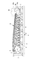
例えば、複数の胴体パネル10の組み合わせ方などに応じて、胴体パネル10に切欠き部16が形成される場合がある。このように、切欠き部16が形成された胴体パネル10について、本実施形態に係る保持治具2は、胴体パネル10を保持できる。この場合、上述した下端支持材8又は側端支持材9とは別に切欠水平端支持材22や切欠側端支持材23が、保持治具2に設置される。切欠水平端支持材22と切欠側端支持材23は、第2の支持体を構成する。切欠水平端支持材22は、例えば、水平材6又は下端支持材8によって、例えば補助材24を介して支持される。
For example, the
切欠水平端支持材22は、把持部3を介して、胴体パネル10の切欠き部16の水平端部を支持する。切欠水平端支持材22は、枠材4の水平材6や下端支持材8よりも上方に位置し、保持治具2に設置される胴体パネル10の機軸方向に沿って、例えば、胴体パネル10の機軸方向に対して平行又は斜め方向になるように配置される。
The notch horizontal
切欠水平端支持材22には、複数の把持部3が互いに間隔を空けて配置される。把持部3が胴体パネル10の切欠き部16の水平端部を下方から支持するように、切欠水平端支持材22は、保持される胴体パネル10よりも下方に位置する。
切欠水平端支持材22の長手方向の一端部は、アーチ材7に結合され、切欠水平端支持材22の長手方向の他端部は、例えば補助材24と結合して設けられる。
A plurality of
One end portion in the longitudinal direction of the notched horizontal
切欠側端支持材23は、胴体パネル10の側端を下方から支持する。切欠側端支持材23は、曲線形状を有する部材であり、保持治具2に設置される胴体パネル10の機軸方向に対して垂直方向の面内に配置される。切欠側端支持材23は、保持治具2に設置される胴体パネル10の切欠き部16の曲率を有する辺の端部に対応して配置される。
The notch side
切欠側端支持材23は、一端が切欠水平端支持材22と結合され、他端が下端支持材8と結合される。切欠側端支持材23の曲線形状、例えば曲率は、製造する胴体パネル10の曲率に対応して設けられる。切欠側端支持材23には、側端支持材9と同様に、複数の把持部3が、切欠側端支持材23の長手方向に沿って、間隔を空けて設けられる。複数の把持部3が胴体パネル10の切欠き部16の端部を把持することで、把持部3によって把持された胴体パネル10は、製造する胴体パネル10の曲率となるように保持される。
The notch side
以上、本実施形態に係る保持治具2は、胴体パネル10の切欠き部16の端部で胴体パネル10を支持する。すなわち、スキン11を有する胴体パネル10は、複数の把持部3によって、胴体パネル10の切欠き部16の端部が把持される。このとき、複数の把持部3は、胴体パネル10の切欠き部16に対応して設けられる切欠水平端支持材22や切欠側端支持材23を介して一体的に支持されている。これにより、切欠き部16の周辺におけるスキン11に生じる撓み等の変形を抑制することができる。
As described above, the holding
また、上述した第1及び第2実施形態において、胴体パネル10の側端は、側端支持材9又は切欠側端支持材23に設けられた把持部3によって把持される場合について説明したが、本発明は、この例に限定されない。例えば、側端支持材9又は切欠側端支持材23には、複数のロッドが、側端支持材9又は切欠側端支持材23の曲線形状に沿って、間隔を空けて設けられる。ロッドは、胴体パネル10の径方向(機軸方向に対して垂直方向)に突出し、突出長さが調整可能な構成を有する。複数のロッドは、保持されるべき胴体パネル10の形状となるように、突出長さが調整される。胴体パネル10が複数のロッドの上面(ロッドの突出端部)に載置されることで、胴体パネル10は、製造する胴体パネル10の曲率となるように保持される。
Further, in the first and second embodiments described above, the case where the side end of the
例えば、製造する胴体パネル10が、機軸方向に沿って曲率が全て同じである単曲面である場合、一端側の側端支持材9におけるロッドの上面を結ぶ曲率と、他端側の側端支持材9におけるロッドの上面を結ぶ曲率は同じである。一方、製造する胴体パネル10が、一軸方向に沿って曲率が変化する複曲面である場合、一端側の側端支持材9におけるロッドの上面を結ぶ曲率は、他端側の側端支持材9におけるロッドの上面を結ぶ曲率よりも大きくなる。
For example, when the
さらに、上述した第1及び第2実施形態では、2本のアーチ材7が同一半径を有する場合について例示したが、本発明はこの例に限定されず、図10に示すように、2本のアーチ材7の半径を異ならせてもよい。製造する胴体パネル10が、機軸方向に沿って曲率が変化する複曲面である場合、胴体パネル10の機軸が水平面に対して平行になるように、胴体パネル10が保持治具1に設置されたとき、胴体パネル10の横断面のうち半径の小さい側が、半径の大きい側に比べて、下方に位置する。その結果、胴体パネル10の半径の小さい側の高さとアーチ材7の高さとの差が大きいと、自動打鋲機36において機軸方向に突出した部品36aが、アーチ材7の胴体パネル10側の側面と干渉する。この場合、図10に示すように、胴体パネル10の横断面のうち半径の小さい側に位置するアーチ材7の高さを低くすることによって、自動打鋲機36において機軸方向に突出した部品36aが、アーチ材7よりも上方に位置するように、自動打鋲機36を設置でき、アーチ材7と自動打鋲機36の干渉を防止できる。
Furthermore, in the first and second embodiments described above, the case where the two
1,2 保持治具
3 把持部
4 枠材
5 支持体
6 水平材
7 アーチ材
8 下端支持材(第1支持材)
9 側端支持材(第2支持材)
10 胴体パネル
11 スキン
12 ストリンガー
16 切欠き部
21,24 補助材
22 切欠水平端支持材
23 切欠側端支持材
31 分割パネル取付けロボット
32 門型自動打鋲機
33 自動打鋲機
34 門型フレーム
35 取付用ロボット
60 固定台
DESCRIPTION OF
9 Side support material (second support material)
DESCRIPTION OF
Claims (11)
板状部材を有する航空機パネルの対向する2辺の端部を把持する複数の把持部と、
前記複数の把持部によって把持される前記航空機パネルに対応して前記水平材とは別に設けられ、前記複数の把持部を一体的に支持する支持体と、
を備え、
前記複数の把持部によって、前記航空機パネルの端部が把持されつつ、前記一軸方向に対して垂直方向に切断した断面が曲線形状となるように前記航空機パネルが保持され、
前記航空機パネルを保持した状態で搬送され得る構成を有する保持治具。 A frame member having a linear horizontal member extending in a uniaxial direction;
A plurality of gripping portions that grip the ends of two opposite sides of an aircraft panel having a plate-like member;
A support body provided separately from the horizontal member corresponding to the aircraft panel gripped by the plurality of gripping portions, and integrally supporting the plurality of gripping portions;
With
Wherein depending on the plurality of gripping portions, wherein while the end portion of the aircraft panel is grasped, the cross section cut in a direction perpendicular to the uniaxial direction is the aircraft panel such that the curved shape is retained,
The holding jig which has the structure which can be conveyed in the state which hold | maintained the said aircraft panel.
前記第1支持材に支持された前記複数の把持部は、前記一軸方向に沿った前記航空機パネルの対向する2辺の端部で前記航空機パネルを把持する請求項1に記載の保持治具。 The support body includes a first support member provided one by one corresponding to each of two opposite sides of the aircraft panel along the uniaxial direction,
2. The holding jig according to claim 1, wherein the plurality of grip portions supported by the first support member grip the aircraft panel at two opposite end portions of the aircraft panel along the uniaxial direction.
前記複数の把持部によって把持される前記航空機パネルに対応して設けられ、前記複数の把持部を一体的に支持する支持体と、
を備え、
前記複数の把持部は、前記航空機パネルの端部を把持しつつ、一軸方向に対して垂直方向に切断した断面が曲線形状となるように前記航空機パネルを保持し、
前記航空機パネルを保持した状態で搬送され得る構成を有し、
前記支持体は、前記一軸方向に沿って、前記航空機パネルの対向する2辺の各辺に対応して1本ずつ設けられる第1支持材を有し、
前記第1支持材に支持された前記複数の把持部は、前記一軸方向に沿った前記航空機パネルの対向する2辺の端部で前記航空機パネルを把持し、
前記第1支持材が固定される位置が、前記航空機パネルの形状に応じて、前記航空機パネルの前記一軸を中心とした周方向に変更可能である保持治具。 A plurality of gripping portions that grip the ends of two opposite sides of an aircraft panel having a plate-like member;
A support body provided corresponding to the aircraft panel gripped by the plurality of gripping portions, and integrally supporting the plurality of gripping portions;
With
The plurality of gripping portions hold the aircraft panel so that a cross section cut in a direction perpendicular to a uniaxial direction has a curved shape while gripping an end portion of the aircraft panel.
Having a configuration capable of being transported while holding the aircraft panel;
The support body includes a first support member provided one by one corresponding to each of two opposite sides of the aircraft panel along the uniaxial direction,
The plurality of gripping portions supported by the first support member grip the aircraft panel at two opposite ends of the aircraft panel along the uniaxial direction .
A holding jig in which a position at which the first support member is fixed can be changed in a circumferential direction around the one axis of the aircraft panel according to a shape of the aircraft panel .
前記第2支持材は、前記一軸を中心にして周方向に沿った前記航空機パネルの対向する2辺の端部で前記航空機パネルを載置する請求項1から4のいずれか1項に記載の保持治具。 The support body has a second support material provided one by one in a plane perpendicular to the uniaxial direction corresponding to the curved shape of each of the two opposite sides of the aircraft panel,
The said 2nd support material mounts the said aircraft panel in the edge part of the 2 sides which the said aircraft panel opposes along the circumferential direction centering | focusing on the said one axis | shaft. Holding jig.
前記第2支持材に支持された前記複数の把持部は、前記一軸を中心にして周方向に沿った前記航空機パネルの対向する2辺で前記航空機パネルを把持する請求項1から4のいずれか1項に記載の保持治具。 The support body has a second support material provided one by one in a plane perpendicular to the uniaxial direction corresponding to the curved shape of each of the two opposite sides of the aircraft panel,
Wherein said plurality of gripping portions which are supported by the second support member may be any of claims 1 to 4 for gripping the aircraft panel two opposite sides of the aircraft panel along a manner circumferentially about the single The holding jig according to item 1.
前記複数の把持部によって把持される前記航空機パネルに対応して設けられ、前記複数の把持部を一体的に支持する支持体と、
を備え、
前記複数の把持部は、前記航空機パネルの端部を把持しつつ、一軸方向に対して垂直方向に切断した断面が曲線形状となるように前記航空機パネルを保持し、
前記航空機パネルを保持した状態で搬送され得る構成を有し、
前記支持体は、前記一軸方向に対して垂直方向の面内に、前記航空機パネルの対向する2辺の各辺の曲線形状に対応して1本ずつ設けられる第2支持材を有し、
前記第2支持材に支持された前記複数の把持部は、前記一軸を中心にして周方向に沿った前記航空機パネルの対向する2辺で前記航空機パネルを把持する保持治具。 A plurality of gripping portions that grip the ends of two opposite sides of an aircraft panel having a plate-like member;
A support body provided corresponding to the aircraft panel gripped by the plurality of gripping portions, and integrally supporting the plurality of gripping portions;
With
The plurality of gripping portions hold the aircraft panel so that a cross section cut in a direction perpendicular to a uniaxial direction has a curved shape while gripping an end portion of the aircraft panel.
Having a configuration capable of being transported while holding the aircraft panel;
The support body has a second support material provided one by one in a plane perpendicular to the uniaxial direction corresponding to the curved shape of each of the two opposite sides of the aircraft panel,
The plurality of grip portions supported by the second support member are holding jigs for gripping the aircraft panel at two opposite sides of the aircraft panel along a circumferential direction around the one axis.
前記切欠き部の端部を把持する複数の第2の把持部と、
前記複数の第2の把持部によって把持される前記切欠き部の端部に対応して設けられ、前記複数の第2の把持部を支持する第2の支持体と、
を更に備える請求項1から8のいずれか1項に記載の保持治具。 The plate member of the aircraft panel has a notch,
A plurality of second gripping portions for gripping end portions of the cutout portions;
A second support that is provided corresponding to an end of the notch that is gripped by the plurality of second gripping portions, and that supports the plurality of second gripping portions;
The holding jig according to any one of claims 1 to 8, further comprising:
前記複数の把持部によって把持される前記航空機パネルに対応して設けられ、前記複数の把持部を一体的に支持する支持体と、
を備え、
前記複数の把持部は、前記航空機パネルの端部を把持しつつ、一軸方向に対して垂直方向に切断した断面が曲線形状となるように前記航空機パネルを保持し、
前記航空機パネルを保持した状態で搬送され得る構成を有し、
前記航空機パネルの前記板状部材が切欠き部を有し、
前記切欠き部の端部を把持する複数の第2の把持部と、
前記複数の第2の把持部によって把持される前記切欠き部の端部に対応して設けられ、前記複数の第2の把持部を支持する第2の支持体と、
を更に備える保持治具。 A plurality of gripping portions that grip the ends of two opposite sides of an aircraft panel having a plate-like member;
A support body provided corresponding to the aircraft panel gripped by the plurality of gripping portions, and integrally supporting the plurality of gripping portions;
With
The plurality of gripping portions hold the aircraft panel so that a cross section cut in a direction perpendicular to a uniaxial direction has a curved shape while gripping an end portion of the aircraft panel.
Having a configuration capable of being transported while holding the aircraft panel;
The plate member of the aircraft panel has a notch,
A plurality of second gripping portions for gripping end portions of the cutout portions;
A second support that is provided corresponding to an end of the notch that is gripped by the plurality of second gripping portions, and that supports the plurality of second gripping portions;
A holding jig.
Priority Applications (7)
| Application Number | Priority Date | Filing Date | Title |
|---|---|---|---|
| JP2016018427A JP6580495B2 (en) | 2016-02-02 | 2016-02-02 | Holding jig |
| CA3011666A CA3011666C (en) | 2016-02-02 | 2016-11-17 | Holding fixture |
| BR112018015490A BR112018015490A2 (en) | 2016-02-02 | 2016-11-17 | retention template |
| PCT/JP2016/084131 WO2017134902A1 (en) | 2016-02-02 | 2016-11-17 | Holding jig |
| CN201680080256.5A CN108602568A (en) | 2016-02-02 | 2016-11-17 | Holding jig |
| EP16889385.7A EP3392154B1 (en) | 2016-02-02 | 2016-11-17 | Holding jig |
| US16/070,434 US10843820B2 (en) | 2016-02-02 | 2016-11-17 | Holding fixture |
Applications Claiming Priority (1)
| Application Number | Priority Date | Filing Date | Title |
|---|---|---|---|
| JP2016018427A JP6580495B2 (en) | 2016-02-02 | 2016-02-02 | Holding jig |
Publications (3)
| Publication Number | Publication Date |
|---|---|
| JP2017136930A JP2017136930A (en) | 2017-08-10 |
| JP2017136930A5 JP2017136930A5 (en) | 2018-06-14 |
| JP6580495B2 true JP6580495B2 (en) | 2019-09-25 |
Family
ID=59499490
Family Applications (1)
| Application Number | Title | Priority Date | Filing Date |
|---|---|---|---|
| JP2016018427A Active JP6580495B2 (en) | 2016-02-02 | 2016-02-02 | Holding jig |
Country Status (7)
| Country | Link |
|---|---|
| US (1) | US10843820B2 (en) |
| EP (1) | EP3392154B1 (en) |
| JP (1) | JP6580495B2 (en) |
| CN (1) | CN108602568A (en) |
| BR (1) | BR112018015490A2 (en) |
| CA (1) | CA3011666C (en) |
| WO (1) | WO2017134902A1 (en) |
Families Citing this family (5)
| Publication number | Priority date | Publication date | Assignee | Title |
|---|---|---|---|---|
| CN206523497U (en) * | 2017-03-14 | 2017-09-26 | 京东方科技集团股份有限公司 | Tool |
| CN110216235B (en) * | 2019-06-03 | 2024-02-09 | 西安飞机工业(集团)有限责任公司 | Flexible fuselage wall plate assembly tool and assembly method based on measured data |
| CN112212775B (en) * | 2020-09-28 | 2022-03-22 | 中国航发贵州黎阳航空动力有限公司 | Cambered surface thin-wall part detection and deformation prevention device and use method |
| KR102451064B1 (en) * | 2021-06-28 | 2022-10-07 | 디와이피엔에프 주식회사 | Jig for shell panel of silo and apparatus for manufacturing shell panel of silo |
| CN114310122B (en) * | 2022-02-08 | 2023-07-18 | 江南造船(集团)有限责任公司 | Shape-preserving tool and clamping unit for T-shaped arc-shaped panel |
Family Cites Families (29)
| Publication number | Priority date | Publication date | Assignee | Title |
|---|---|---|---|---|
| SE451185B (en) | 1985-03-11 | 1987-09-14 | Atlas Copco Ab | RIVING DEVICE FOR JOINING TWO OR MORE SITE SECTIONS |
| US4691905A (en) * | 1985-04-18 | 1987-09-08 | Nissan Motor Co., Ltd. | Machine for holding workpiece |
| US5033178A (en) * | 1988-07-06 | 1991-07-23 | The Boeing Company | Assembly jig and method for making wing panels |
| US4995146A (en) * | 1988-10-26 | 1991-02-26 | The Boeing Company | Assembly jig and method for making wing spars |
| JPH04336997A (en) * | 1991-05-14 | 1992-11-25 | Bridgestone Cycle Co | Boring machine and boring method of large size panel |
| US5588554A (en) * | 1992-09-21 | 1996-12-31 | The Boeing Company | Feeding fasteners to a workpiece |
| US5560102A (en) * | 1992-10-13 | 1996-10-01 | The Boeing Company | Panel and fuselage assembly |
| US5350162A (en) * | 1993-03-08 | 1994-09-27 | Cushing Meredith K | Apparatus for assembling reinforcing bar pier cages |
| US5617622A (en) * | 1995-06-06 | 1997-04-08 | Anderson; Tommy G. | Rotatable work platform with clamps for wall and truss fabrication |
| ES2146140B1 (en) * | 1996-10-15 | 2001-04-01 | Torres Martinez M | MACHINE FOR SUPPORT AND MACHINING OF PARTS. |
| DE29722276U1 (en) * | 1997-12-17 | 1999-05-06 | Kuka Schweissanlagen Gmbh | Clamping device for workpieces |
| GB9925610D0 (en) * | 1999-10-29 | 1999-12-29 | British Aerospace | Workpiece support |
| SE523035C2 (en) * | 2000-04-13 | 2004-03-23 | Saab Ab | Tools for fixing hull details |
| CA2324820C (en) * | 2000-10-30 | 2004-05-04 | Clayton Dean Babchuk | Workpiece support apparatus |
| ATE264161T1 (en) * | 2001-01-16 | 2004-04-15 | Airbus Gmbh | HOLDING DEVICE FOR HOLDING LARGE-FORMAT COMPONENTS |
| US20030034602A1 (en) * | 2001-08-18 | 2003-02-20 | Kavanaugh Chris J. | Universal holding fixture |
| JP2003329010A (en) * | 2002-05-16 | 2003-11-19 | Koganei Corp | Clamping unit |
| US7076856B2 (en) * | 2002-11-14 | 2006-07-18 | The Boeing Company | Adjustable system and method for supporting and joining structural members |
| CA2449918A1 (en) * | 2002-11-19 | 2004-05-19 | Vinode Ramnauth | Apparatus and method for moving frameworks between workstations |
| US20040187291A1 (en) * | 2003-03-31 | 2004-09-30 | Richard Syrek | Method for changing fixtures used to position a plurality of different workpieces on an assembly line |
| US7765662B2 (en) * | 2006-09-14 | 2010-08-03 | Mckown Jeffrey A | Holding fixture for machining bearing caps |
| JP5035533B2 (en) | 2007-09-24 | 2012-09-26 | 豊和工業株式会社 | Clamping device |
| JP2013198918A (en) * | 2012-03-23 | 2013-10-03 | Mitsubishi Heavy Ind Ltd | Automatic riveting apparatus |
| US9156510B2 (en) * | 2012-10-17 | 2015-10-13 | Btm Company Llc | Clamp mounting system |
| DE102013004598A1 (en) * | 2013-03-15 | 2014-09-18 | Dürr Systems GmbH | itsplattform |
| KR101459465B1 (en) * | 2013-06-14 | 2014-11-07 | 현대자동차 주식회사 | Loading jig of trunk lid and tailgate |
| JP6271902B2 (en) * | 2013-08-01 | 2018-01-31 | 三菱重工業株式会社 | Support jig and aircraft assembling method using the same |
| CN103600249A (en) * | 2013-11-15 | 2014-02-26 | 长春轨道客车股份有限公司 | Automatic fixture for machining large parts of rail vehicles |
| CN104400086B (en) * | 2014-10-10 | 2016-07-06 | 南京航空航天大学 | Aircraft skin mirror image method for milling and equipment |
-
2016
- 2016-02-02 JP JP2016018427A patent/JP6580495B2/en active Active
- 2016-11-17 CA CA3011666A patent/CA3011666C/en not_active Expired - Fee Related
- 2016-11-17 US US16/070,434 patent/US10843820B2/en active Active
- 2016-11-17 EP EP16889385.7A patent/EP3392154B1/en active Active
- 2016-11-17 WO PCT/JP2016/084131 patent/WO2017134902A1/en active Application Filing
- 2016-11-17 CN CN201680080256.5A patent/CN108602568A/en active Pending
- 2016-11-17 BR BR112018015490A patent/BR112018015490A2/en not_active IP Right Cessation
Also Published As
| Publication number | Publication date |
|---|---|
| CA3011666C (en) | 2021-02-09 |
| EP3392154A4 (en) | 2018-12-05 |
| CA3011666A1 (en) | 2017-08-10 |
| WO2017134902A1 (en) | 2017-08-10 |
| US10843820B2 (en) | 2020-11-24 |
| US20190023417A1 (en) | 2019-01-24 |
| EP3392154B1 (en) | 2021-01-06 |
| BR112018015490A2 (en) | 2018-12-18 |
| JP2017136930A (en) | 2017-08-10 |
| EP3392154A1 (en) | 2018-10-24 |
| CN108602568A (en) | 2018-09-28 |
Similar Documents
| Publication | Publication Date | Title |
|---|---|---|
| JP6580495B2 (en) | Holding jig | |
| JP6650147B2 (en) | Aircraft panel manufacturing method and aircraft panel manufacturing system | |
| JP6513585B2 (en) | Shape holding jig and aircraft panel manufacturing method | |
| JP4937361B2 (en) | Production equipment | |
| JP2017136931A5 (en) | ||
| EP1797973A1 (en) | Combined panel bender-press brake machine | |
| WO2018088140A1 (en) | Component production method, and component production system | |
| JP6513584B2 (en) | Holding jig fixing device | |
| CN208214744U (en) | A kind of semi-automatic assembling hot riveting machine of automobile instrument index | |
| CN113109170A (en) | Composite material long beam strength test device | |
| KR101653378B1 (en) | Rivetting Apparatus having Multiple Rivetting Block | |
| KR101723958B1 (en) | Assistant robot with gravity compensation with multi degrees of freedom | |
| KR200316700Y1 (en) | drilling zig | |
| CN115502747A (en) | Positioning and pressing device for skin or wall plate forming assembly closed area | |
| JPS5848801A (en) | Measuring device for dimension of plural points from standard surface | |
| JPH078178U (en) | Vehicle hood positioning jig |
Legal Events
| Date | Code | Title | Description |
|---|---|---|---|
| A621 | Written request for application examination |
Free format text: JAPANESE INTERMEDIATE CODE: A621 Effective date: 20180326 |
|
| A521 | Written amendment |
Free format text: JAPANESE INTERMEDIATE CODE: A523 Effective date: 20180424 |
|
| A131 | Notification of reasons for refusal |
Free format text: JAPANESE INTERMEDIATE CODE: A131 Effective date: 20190108 |
|
| A521 | Written amendment |
Free format text: JAPANESE INTERMEDIATE CODE: A523 Effective date: 20190307 |
|
| TRDD | Decision of grant or rejection written | ||
| A01 | Written decision to grant a patent or to grant a registration (utility model) |
Free format text: JAPANESE INTERMEDIATE CODE: A01 Effective date: 20190730 |
|
| A61 | First payment of annual fees (during grant procedure) |
Free format text: JAPANESE INTERMEDIATE CODE: A61 Effective date: 20190828 |
|
| R150 | Certificate of patent or registration of utility model |
Ref document number: 6580495 Country of ref document: JP Free format text: JAPANESE INTERMEDIATE CODE: R150 |