JP6580475B2 - Wireless power supply system - Google Patents
Wireless power supply system Download PDFInfo
- Publication number
- JP6580475B2 JP6580475B2 JP2015238315A JP2015238315A JP6580475B2 JP 6580475 B2 JP6580475 B2 JP 6580475B2 JP 2015238315 A JP2015238315 A JP 2015238315A JP 2015238315 A JP2015238315 A JP 2015238315A JP 6580475 B2 JP6580475 B2 JP 6580475B2
- Authority
- JP
- Japan
- Prior art keywords
- coil
- power
- permanent magnet
- receiving device
- voltage
- Prior art date
- Legal status (The legal status is an assumption and is not a legal conclusion. Google has not performed a legal analysis and makes no representation as to the accuracy of the status listed.)
- Expired - Fee Related
Links
Images


Description
本発明は、建物の天井や壁などに設置されるワイヤレス給電システムに関する。 The present invention relates to a wireless power feeding system installed on a ceiling or wall of a building.
建物の天井や壁などの躯体に移動可能に設置されたワイヤレス給電システムが知られている(例えば、特許文献1参照)。このワイヤレス給電システムは、躯体の室内側とは反対側に設置されて電力を供給する給電装置と、躯体の室内側に設置され、給電装置から電力をワイヤレスで受電する受電装置と、を備えている。受電装置には、受電された電力で動作する照明などの電気機器が接続される。給電装置と受電装置は、それぞれ永久磁石を有する。給電装置と受電装置は、2つの永久磁石の間に働く磁気吸引力によって、躯体を挟んで互いに引き合う。 There is known a wireless power feeding system that is movably installed on a building such as a ceiling or a wall of a building (see, for example, Patent Document 1). The wireless power feeding system includes a power feeding device that is installed on the opposite side of the interior of the housing and supplies power, and a power receiving device that is installed on the indoor side of the housing and wirelessly receives power from the power feeding device. Yes. The power receiving device is connected to an electric device such as a lighting that operates with the received power. Each of the power feeding device and the power receiving device has a permanent magnet. The power feeding device and the power receiving device are attracted to each other with the housing sandwiched between them by the magnetic attractive force acting between the two permanent magnets.
ユーザが受電装置を躯体上で移動させることにより、磁気吸引力の働きで給電装置と受電装置とが一体となって移動する。従って、受電装置は、躯体上の任意の位置で電力を受電できる。 When the user moves the power receiving device on the housing, the power feeding device and the power receiving device move together by the magnetic attraction force. Therefore, the power receiving device can receive power at an arbitrary position on the housing.
このようなワイヤレス給電システムにおいて、永久磁石の磁力が強すぎる場合、給電装置および受電装置を移動させることが難しい。また、永久磁石の磁力が弱すぎる場合、給電中などに受電装置が落下する恐れがある。 In such a wireless power feeding system, when the magnetic force of the permanent magnet is too strong, it is difficult to move the power feeding device and the power receiving device. Further, when the magnetic force of the permanent magnet is too weak, the power receiving device may fall during power feeding.
本発明は、このような課題に鑑みてなされ、その目的は、受電装置の落下を抑制した上で受電装置を容易に移動させることができるワイヤレス給電システムを提供することにある。 The present invention has been made in view of such a problem, and an object thereof is to provide a wireless power feeding system capable of easily moving a power receiving device while suppressing the falling of the power receiving device.
上記課題を解決するための本発明のある態様のワイヤレス給電システムは、
第1の永久磁石を有し、建物の躯体の一方側に配置されて電力を供給する給電装置と、
第2の永久磁石を有し、前記躯体の他方側に配置されて前記第1の永久磁石と前記第2の永久磁石との間の磁気吸引力により前記給電装置に引き寄せられ、前記給電装置から電力をワイヤレスで受電する受電装置と、を備え、
前記給電装置は、
前記第1の永久磁石と前記第2の永久磁石との間に磁界を発生させる第1のコイルと、
前記受電装置を移動させるときに、前記第1の永久磁石と前記第2の永久磁石との間の磁界を弱める磁界が前記第1のコイルに発生するように、前記第1のコイルに電圧を印加する電源と、
を有することを特徴とする。
A wireless power supply system according to an aspect of the present invention for solving the above problems is
A power supply device that has a first permanent magnet and is arranged on one side of a building housing to supply power;
A second permanent magnet that is disposed on the other side of the housing and is attracted to the power feeding device by a magnetic attraction between the first permanent magnet and the second permanent magnet; A power receiving device for receiving power wirelessly,
The power supply device
A first coil for generating a magnetic field between the first permanent magnet and the second permanent magnet;
When the power receiving device is moved, a voltage is applied to the first coil such that a magnetic field that weakens the magnetic field between the first permanent magnet and the second permanent magnet is generated in the first coil. Power to be applied,
It is characterized by having.
この態様によれば、第1の永久磁石と第2の永久磁石との間の磁界を弱める磁界を第1のコイルに発生させるので、必要な磁気吸引力が得られる磁力を有する第1の永久磁石および第2の永久磁石を用いた上で、受電装置を移動させるときに給電装置と受電装置との間の磁気吸引力を弱くすることができる。従って、受電装置の落下を抑制した上で受電装置を容易に移動させることができる。 According to this aspect, since the first coil generates a magnetic field that weakens the magnetic field between the first permanent magnet and the second permanent magnet, the first permanent having a magnetic force that can obtain a necessary magnetic attractive force. The magnetic attraction force between the power feeding device and the power receiving device can be weakened when the power receiving device is moved after using the magnet and the second permanent magnet. Therefore, it is possible to easily move the power receiving device while suppressing the falling of the power receiving device.
本発明によれば、受電装置の落下を抑制した上で受電装置を容易に移動させることができる。 According to the present invention, it is possible to easily move the power receiving device while suppressing the falling of the power receiving device.
以下、実施形態、変形例では、同一の構成要素に同一の符号を付し、重複する説明を省略する。また、各図面では、説明の便宜のため、構成要素の一部を適宜省略したり、構成要素の寸法を適宜拡大、縮小して示す。 Hereinafter, in the embodiment and the modification, the same reference numerals are given to the same components, and the duplicate description is omitted. In the drawings, for convenience of explanation, some of the components are omitted as appropriate, and the dimensions of the components are appropriately enlarged and reduced.
[第1の実施形態]
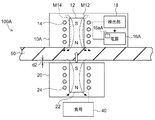
図1(a)は、第1の実施形態に係るワイヤレス給電システム100の概略的な構成を示す縦断面図である。図1(b)は、図1(a)の第1の永久磁石12と第1のコイル14の上面図である。図1(a)に示すように、ワイヤレス給電システム100は、給電装置10と、受電装置20と、を備える。ワイヤレス給電システム100には、照明などの負荷40が接続可能である。
[First Embodiment]
FIG. 1A is a longitudinal sectional view illustrating a schematic configuration of a wireless
給電装置10は、第1の永久磁石12と、第1のコイル14と、電源16と、を有する。給電装置10は、建物の天井、壁または床などの躯体50の一方側、即ち室内側とは反対側に配置されて、受電装置20に対してワイヤレスで電力を供給する。本実施形態では、躯体50は天井である一例について説明する。
The
受電装置20は、第2の永久磁石22と、第2のコイル24と、を有する。受電装置20は、躯体50の他方側、即ち室内側に配置されて第1の永久磁石12と第2の永久磁石22との間の磁気吸引力により躯体50および給電装置10に引き寄せられる。これにより、給電装置10および受電装置20は、躯体50に固定される。受電装置20は、給電装置10から電力をワイヤレスで受電する。
The
棒状の第1の永久磁石12のN極は、躯体50側に配置されている。第1の永久磁石のN極からS極に向かう方向は、躯体50の面に垂直な方向と略等しい。
The north pole of the rod-shaped first
第1のコイル14は、第1の永久磁石12の周囲に巻回されている。第1のコイル14の中心軸の方向は、躯体50の面に垂直な方向と略等しい。このような配置により、第1のコイル14は、第1の永久磁石12と第2の永久磁石22との間に磁界を発生させることができる。即ち、第1のコイル14による磁界は、第1の永久磁石12と第2の永久磁石22との間における、第1の永久磁石12と第2の永久磁石22とによる磁界に影響を与える。
The
電源16は、ユーザの指示に応じた制御を行う制御部16aを有し、制御部16aの制御に従って、第1のコイル14に交流電圧または直流電圧を印加する。電源16の具体的な機能は後述する。
The
棒状の第2の永久磁石22のS極は、躯体50側に配置されている。第2の永久磁石のN極からS極に向かう方向は、躯体50の面に垂直な方向と略等しい。第2の永久磁石22のS極が第1の永久磁石12のN極と向かい合うように、受電装置20は配置されている。第1の永久磁石12および第2の永久磁石22は、給電中に受電装置20が落下しない磁気吸引力が得られる磁力を有する。
第1の永久磁石12のN極とS極とを逆向きに配置して、第2の永久磁石22のN極とS極とを逆向きに配置してもよい。
The south pole of the rod-shaped second
The N pole and S pole of the first
第2のコイル24は、第2の永久磁石22の周囲に巻回されている。第2のコイル24の中心軸の方向は、躯体50の面に垂直な方向と略等しい。このような配置により、第1のコイル14に発生した磁界は、第2のコイル24の内側に到達する。
The
受電装置20には、受電された電力で動作する負荷40が接続可能である。負荷40は、例えば、受電装置20に吊り下げられる。負荷40は、特に限定されないが、例えば、リモコンなどによって操作可能な通信機能付き負荷であってもよい。負荷40の一例として、照明や照明付き扇風機などを挙げることができる。
A
次に、ワイヤレス給電システム100の動作について説明する。給電装置10は、ユーザの指示に従って、例えば、オフモードと、給電モードと、移動モードと、取り外しモードと、固定モードと、の何れかに切り替えできる。
Next, the operation of the wireless
給電装置10は、ユーザの操作に応じてリモコンなどの通信機器から出力される指示に従って、モードを切り替える。ワイヤレス給電システム100は、複数組の給電装置10および受電装置20を備えてもよい。このような場合に、ユーザは、リモコンなどの通信機器によって複数組の中から所望の組を個別に選択して、モードを切り替えることができる。また、給電装置10には、ユーザの操作に応じてモードを切り替え可能な操作パネルが配線によって接続されていてもよい。
The
ユーザは、電源16が第1のコイル14に電圧を印加していないオフモードのときに、受電装置20を給電装置10に向かい合うように躯体50に取り付けておく。前述のように、第1の永久磁石2と第2の永久磁石22との間の磁気吸引力によって、給電装置10および受電装置20は躯体50に固定される。
The user attaches the
(給電モード)
給電モードは、ワイヤレス給電を行うためのモードである。電源16は、給電モードにおいて、第1のコイル14に交流電圧を印加する。これにより、第1のコイル14に発生する磁界が変動し、電磁誘導によって第2のコイル24に起電力が発生し、第1のコイル14から第2のコイル24にワイヤレスで電力が供給される。交流電圧の振幅と周波数は、所望の電力が伝送できるように設定すればよい。電磁誘導方式に替えて磁界共鳴方式を用いて給電してもよい。
(Power supply mode)
The power supply mode is a mode for performing wireless power supply. The
このように、ワイヤレス給電システム100ではワイヤレスで電力を供給するので、負荷40に給電するためのコンセントや引掛シーリングを天井等に設ける必要がない。従って、天井等の見栄えがよくなる。
Thus, since the wireless
ここで、給電中に第1のコイル14に発生する磁界は、第1のコイル14の内側において、透磁率が高い第1の永久磁石12に集中する。即ち、第1の永久磁石12が存在しないと仮定した場合と比較して、第1のコイル14の内側の磁界は、より第1のコイル14の中心軸側に集中する。これにより、第1のコイル14の外側の磁界も影響を受け、その広がりが抑制される。結果として、第1の永久磁石12が存在しないと仮定した場合と比較して、第1のコイル14および第2のコイル24から周囲に漏れる不要電磁場放射を抑制することができる。そのため、周囲の電子機器に対する電磁妨害や、周囲の人体に対する磁界曝露を軽減させることができる。このような効果は、ワイヤレス給電システム100が大電力用のものである場合には、特に顕著となる。
Here, the magnetic field generated in the
(移動モード)
図2は、図1のワイヤレス給電システム100の移動モードを説明する図である。移動モードは、給電装置10および受電装置20を移動させるためのモードである。
電源16は、移動モードにおいて、第1の永久磁石12と第2の永久磁石22との間の磁界を弱める磁界が第1のコイル14に発生するように、第1のコイル14に直流電圧を印加する。従って、ワイヤレス給電は停止される。具体的には、電源16は、第1の永久磁石12による磁界の方向と逆方向の磁界を第1のコイル14に発生させる。即ち、第1のコイル14による磁束線M14の方向は、第1の永久磁石12による磁束線M12の方向と逆方向である。
(Move mode)
FIG. 2 is a diagram for explaining a movement mode of the wireless
The
これにより、給電装置10と受電装置20との間の磁気吸引力を弱くすることができる。そのため、給電装置10が躯体50に押しつけられる力と、受電装置20が躯体50に押しつけられる力とが弱くなり、受電装置20と躯体50との間に視認できない程度の微少な隙間d1が形成される。よって、静止摩擦力が働く状態から動摩擦力が働く状態に変化し、給電装置10と躯体50との間の摩擦力および受電装置20と躯体50との間の摩擦力が低減される。従って、ユーザが受電装置20を躯体50上で移動させることにより、給電装置10と受電装置20とを一体的に容易に移動させることができる。その結果、受電装置20は、躯体50上の任意の位置で電力を受電できる。このように、ユーザは、負荷40の種類や室内のレイアウト変更などに応じて、給電位置の変更を容易に行うことができる。
Thereby, the magnetic attraction between the
このとき、受電装置20が落下しない磁気吸引力を保つことができるよう、印加する直流電圧の大きさを予め調整しておく。
At this time, the magnitude of the DC voltage to be applied is adjusted in advance so that the magnetic attraction force that does not drop the
電源16は、直流電圧に替えて交流電圧を印加してもよい。この場合、交流電圧の周波数に応じて、第1の永久磁石12と第2の永久磁石22との間の磁界が強まる第1期間と、この磁界が弱まる第2期間とが交互に繰り返される。第2期間のそれぞれにおいて摩擦力が低減されるため、給電装置10と受電装置20とを第2期間毎に容易に移動させることができる。
また、交流電圧を印加することにより、移動モードにおいても受電装置20に電力を供給し続けることもできる。
The
In addition, by applying an AC voltage, it is possible to continue supplying power to the
交流電圧のデューティ比は、第2期間が第1期間より長くなるように設定されてもよい。これにより、第1期間と第2期間が等しいデューティ比が50%の場合と比較して、移動がより容易になる。 The duty ratio of the AC voltage may be set so that the second period is longer than the first period. Thereby, compared with the case where the duty ratio in which the 1st period and the 2nd period are equal is 50%, movement becomes easier.
なお、移動モードへの切り替えは、通信機器や操作パネルからの指示以外によって行われてもよい。例えば、物体の接触を検出するセンサまたは温度を検出するセンサを受電装置20に設け、ユーザが受電装置20に触れたことがセンサにより検出されたときに移動モードに切り替えてもよい。
Note that switching to the movement mode may be performed by an instruction other than an instruction from the communication device or the operation panel. For example, a sensor that detects contact of an object or a sensor that detects temperature may be provided in the
(取り外しモード)
図3は、図1のワイヤレス給電システム100の取り外しモードを説明する図である。取り外しモードは、受電装置20を躯体50から取り外すためのモードである。
電源16は、取り外しモードにおいて、第1の永久磁石12と第2の永久磁石22との間の磁界が、上述した移動モードの磁界より弱くなるように、第1のコイル14に直流電圧を印加する。即ち、電源16は、移動モードの直流電圧よりも高い直流電圧を第1のコイル14に印加する。これにより、給電装置10と受電装置20との間の磁気吸引力を移動モードよりも弱くすることができる。従って、ユーザは、受電装置20を容易に取り外すことができる。
(Removal mode)
FIG. 3 is a diagram illustrating a removal mode of the wireless
In the removal mode, the
このように、使用しない受電装置20をユーザが取り外すことにより、天井等の見栄えが良くなり、使用しない受電装置20が邪魔になることもない。取り外された受電装置20は、必要な時に、第1の永久磁石2と第2の永久磁石22との間の磁気吸引力によって容易に取り付けることができる。
Thus, when the user removes the unused
なお、取り外しモードにおいても、電源16は、直流電圧に替えて交流電圧を印加してもよい。この場合、交流電圧のデューティ比は、第2期間が第1期間より長くなるように設定される。これにより、デューティ比が50%の場合と比較して、平均的な磁気吸引力を低減させることができ、取り外しが容易になる。
Even in the removal mode, the
(固定モード)
図4は、図1のワイヤレス給電システム100の固定モードを説明する図である。固定モードは、受電装置20を躯体50により強く固定するためのモードである。
電源16は、固定モードにおいて、第1の永久磁石12と第2の永久磁石22との間の磁界を強める磁界が第1のコイル14に発生するように、第1のコイル14に直流電圧を印加する。具体的には、電源16は、移動モード及び取り外しモードの直流電圧とは逆極性の直流電圧を第1のコイル14に印加し、第1の永久磁石12による磁界の方向と同方向の磁界を第1のコイル14に発生させる。即ち、第1のコイル14による磁束線M14の方向は、第1の永久磁石12による磁束線M12の方向と同方向である。これにより、給電装置10と受電装置20との間の磁気吸引力を、第1の永久磁石12と第2の永久磁石22のみを用いる場合よりも強くすることができる。従って、より確実に受電装置20の落下を抑制できる。固定モードは、より重い負荷40を用いる場合などに好適である。
(Fixed mode)
FIG. 4 is a diagram illustrating a fixed mode of the wireless
The
なお、前述の給電モードにおいて、電源16は、交流電圧に加えて固定モードの直流電圧を第1のコイル14に印加してもよい。これにより、交流電圧のみを印加する場合より平均的な磁気吸引力が増加するので、ワイヤレス給電中にも、より確実に受電装置20の落下を抑制できる。
In the above power supply mode, the
以上で説明したように、本実施形態によれば、第1のコイル14が第1の永久磁石12の周囲に巻回されているので、第1の永久磁石12による磁界の方向と逆方向の磁界を第1のコイル14に発生させることにより、第1の永久磁石12と第2の永久磁石22との間の磁界を弱めることができる。これにより、給電モードで必要な磁気吸引力が得られる磁力を有する第1の永久磁石12および第2の永久磁石22を用いた上で、移動モードおよび取り外しモードでは給電装置10と受電装置20との間の磁気吸引力を弱くすることができる。従って、給電装置10および受電装置20の移動と、受電装置20の取り外しとを容易に行うことができる。
As described above, according to the present embodiment, since the
また、給電モードでは、第1の永久磁石12および第2の永久磁石22によって、移動モードおよび取り外しモードより強い磁気吸引力で受電装置20を躯体50に引き寄せることができる。従って、受電装置20の落下を抑制できる。
In the power supply mode, the first
以上のように、受電装置20の落下を抑制した上で、給電装置10および受電装置20を容易に移動させることができる。
As described above, the
さらに、第1のコイル14によって磁気吸引力の調整および電力供給の両方を行うことができるので、磁気吸引力の調整用のコイルと給電用コイルとを別々に設ける必要が無く、ワイヤレス給電システム100の構成を簡略化できる。
Furthermore, since both the magnetic attraction force adjustment and the power supply can be performed by the
[第2の実施形態]
第2の実施形態では、受電装置20が躯体50から離れたことが検出された場合に、磁気吸引力を強くする。以下では、第1の実施形態との相違点を中心に説明する。
[Second Embodiment]
In the second embodiment, when it is detected that the
図5は、第2の実施形態に係るワイヤレス給電システム100Aの概略的な構成を示す縦断面図である。給電装置10Aは、受電装置20が躯体50から離れたことを表す物理量を検出する検出部18を備える。本実施形態では、検出部18は、物理量として第1のコイルの電流または電圧を検出する。従って、簡単な構成で受電装置が躯体から離れたことを検出できる。
FIG. 5 is a longitudinal sectional view showing a schematic configuration of a wireless
移動中に受電装置20が躯体50から離れ、隙間d1が隙間d2に大きくなると、第2の永久磁石22と第1のコイル14との間の距離が広がるため、第1のコイル14内の磁界が変化する。これにより、第1のコイル14の電流および電圧が瞬間的に変化する。
When the
電源16Aは、制御部16aAの制御に従って、検出部18で検出された物理量に基づいて動作する。即ち、電源16Aは、移動モードにおいて、第1のコイル14の電流または電圧に基づいて、受電装置20が躯体50から離れた場合に、第1の永久磁石12と第2の永久磁石22との間の磁界を強める磁界が第1のコイル14に発生するように、第1のコイル14に直流電圧を印加する。具体的には、電源16Aは、電流または電圧の変化量が予め定められた閾値を超えた場合に、第1のコイル14に直流電圧を印加する。これにより、磁気吸引力を強くできるので、移動中に受電装置20が誤って落下することを抑制できる。即ち、落下を前もって検知して瞬時に対応できるメカニズムが設けられているので、第1の実施形態よりも安全性を高めることができる。
The
電源16Aは、磁気吸引力を強くした後、磁気吸引力を移動モードの値に弱めてもよい。これにより、再び移動を容易に行うことができる。
The
第1のコイル14の電流または電圧の変化量を簡単な構成で精度良く検出するために、電源16Aは、移動モードにおいて直流電圧を第1のコイル14に印加することが好ましい。
In order to accurately detect the amount of change in the current or voltage of the
なお、検出部18は、物理量として躯体50と受電装置20との間の距離を検出する距離センサであってもよい。
The
以上、実施の形態に基づき本発明を説明したが、実施の形態は、本発明の原理、応用を示すにすぎない。また、実施の形態には、請求の範囲に規定された本発明の思想を逸脱しない範囲において、多くの変形例や配置の変更が可能である。 As mentioned above, although this invention was demonstrated based on embodiment, embodiment only shows the principle and application of this invention. In the embodiment, many modifications and arrangements can be made without departing from the spirit of the present invention defined in the claims.
[第1の変形例]
図示は省略するが、第1のコイル14は、第1の永久磁石12に巻回されず、第1の永久磁石12に隣り合う位置に配置され、第2のコイル24は、第2の永久磁石22に巻回されず、第2の永久磁石22に隣り合う位置に配置されてもよい。第1のコイル14は、第1の永久磁石12と第2の永久磁石22との間に磁界を発生させる位置に配置される。第1のコイル14と第2のコイル24は、それらの中心軸同士がほぼ一致する位置に配置される。第1のコイル14に交流電圧を印加することにより、第1のコイル14から第2のコイル24にワイヤレス給電される。
[First Modification]
Although illustration is omitted, the
第1の変形例によれば、第1のコイル14と第2のコイル24のループの内径は、第1の永久磁石12と第2の永久磁石22の太さとは無関係に設定することができる。そのため、ワイヤレス給電システム100の設計の自由度を向上できる。
また、第1の実施形態または第2の実施形態の効果も得られる。ただし、第1の変形例では、第1のコイル14および第2のコイル24を配置するスペースの分だけ、給電装置10および受電装置20は第1の実施形態または第2の実施形態よりも大きくなる。
According to the first modification, the inner diameters of the loops of the
Moreover, the effect of 1st Embodiment or 2nd Embodiment is also acquired. However, in the first modification, the
[第2の変形例]
図示は省略するが、給電装置10は、第1のコイル14に加えて給電用コイルを有し、受電装置20は、第2のコイル24を有さず、受電用コイルを有してもよい。給電用コイルと受電用コイルは、専らワイヤレス給電に用いられる。そのため、給電用コイルと受電用コイルは、第1の永久磁石12と第2の永久磁石22との間の磁界に影響を与えない位置に設けられても良い。第1のコイル14は、第1の実施形態のように第1の永久磁石12に巻回されてもよく、第1の変形例のように第1の永久磁石12に隣り合う位置に配置されてもよい。
[Second Modification]
Although illustration is omitted, the
あるいは、給電装置10に替えて受電装置20が、第1のコイル14と、第1の永久磁石12と第2の永久磁石22との間の磁界を弱める磁界を第1のコイル14に発生させる電源とを有してもよい。即ち、給電装置10は、第1のコイル14を有さず、給電用コイルを有し、電源16は専らワイヤレス給電に用いられてもよい。受電装置20は、第1のコイル14と、受電用コイルと、第1のコイル14用の電源とを有してもよい。受電装置20の電源は、ワイヤレス給電には用いられないため、電力供給能力が低い電池でもよい。
Alternatively, the
第2の変形例によれば、磁気吸引力を調整するための第1のコイル14とは別に給電用コイルと受電用コイルを設けているので、給電用コイルと受電用コイルの設置位置の自由度が第1の実施形態より高い。例えば、躯体50に取り付けられた時の受電装置20のバランスが良くなるように、第2の永久磁石22は、受電装置20の重心に対応する位置に配置されることが好ましいが、給電用コイルと受電用コイルの設置位置にはこのような制約が無い。よって、ワイヤレス給電システム100の設計の自由度を向上できる。
According to the second modification, since the power supply coil and the power reception coil are provided separately from the
また、室内側の受電装置20が第1のコイル14と電源とを有する構成では、受電装置20にユーザの手が届き易いため、電源の故障に対応し易い。
また、第1の実施形態または第2の実施形態の効果も得られる。ただし、第2の変形例では、少なくとも給電用コイルおよび受電用コイルを配置するスペースの分だけ、給電装置10および受電装置20は第1の実施形態または第2の実施形態よりも大きくなる。
In addition, in the configuration in which the indoor
Moreover, the effect of 1st Embodiment or 2nd Embodiment is also acquired. However, in the second modified example, the
以上の実施形態、変形例により具体化される発明を一般化すると、以下の技術的思想が導かれる。 Generalizing the invention embodied by the above embodiments and modifications leads to the following technical idea.
前述の課題を解決するための手段に記載の態様のワイヤレス給電システムにおいて、
前記給電装置は、前記受電装置が前記躯体から離れたことを表す物理量を検出する検出部を有し、
前記電源は、検出された前記物理量に基づいて、前記受電装置が前記躯体から離れた場合に、前記第1の永久磁石と前記第2の永久磁石との間の磁界を強める磁界が前記第1のコイルに発生するように、前記第1のコイルに電圧を印加してもよい。
この態様によれば、受電装置が躯体から離れた場合に磁気吸引力を強くできるので、移動中に受電装置が誤って落下することを抑制できる。
In the wireless power supply system according to the aspect described in the means for solving the aforementioned problems,
The power supply device has a detection unit that detects a physical quantity indicating that the power receiving device is separated from the housing,
Based on the detected physical quantity, the power source has a magnetic field that enhances a magnetic field between the first permanent magnet and the second permanent magnet when the power receiving device is separated from the housing. A voltage may be applied to the first coil so as to occur in the first coil.
According to this aspect, since the magnetic attractive force can be increased when the power receiving device is separated from the housing, it is possible to prevent the power receiving device from being accidentally dropped during movement.
前述の態様のワイヤレス給電システムにおいて、前記検出部は、前記物理量として前記第1のコイルの電流または電圧を検出してもよい。
この態様によれば、簡単な構成で受電装置が躯体から離れたことを検出できる。
In the wireless power supply system according to the aspect described above, the detection unit may detect the current or voltage of the first coil as the physical quantity.
According to this aspect, it is possible to detect that the power receiving device is separated from the housing with a simple configuration.
前述の態様のワイヤレス給電システムにおいて、
前記第1のコイルは、前記第1の永久磁石の周囲に巻回され、
前記受電装置は、前記第2の永久磁石の周囲に巻回された第2のコイルを有し、
前記電源は、前記第1のコイルに交流電圧を印加し、これにより前記第1のコイルから前記第2のコイルに電力が供給されてもよい。
この態様によれば、第1のコイルによって磁気吸引力の調整および電力供給の両方を行うことができるので、ワイヤレス給電システムの構成を簡略化できる。
In the wireless power supply system of the above aspect,
The first coil is wound around the first permanent magnet;
The power receiving device has a second coil wound around the second permanent magnet,
The power supply may apply an AC voltage to the first coil, whereby electric power may be supplied from the first coil to the second coil.
According to this aspect, since both the magnetic attraction force adjustment and the power supply can be performed by the first coil, the configuration of the wireless power feeding system can be simplified.
前述の態様のワイヤレス給電システムにおいて、前記給電装置に替えて前記受電装置が前記第1のコイルと前記電源とを有してもよい。
この態様によれば、ワイヤレス給電システムの設計の自由度を向上できる。
In the wireless power feeding system according to the above aspect, the power receiving device may include the first coil and the power source instead of the power feeding device.
According to this aspect, the degree of freedom in designing the wireless power feeding system can be improved.
10,10A…給電装置、12…第1の永久磁石、14…第1のコイル、16,16A…電源、18…検出部、20…受電装置、22…第2の永久磁石、24…第2のコイル、50…躯体、100,100A…ワイヤレス給電システム。
DESCRIPTION OF
Claims (11)
第2の永久磁石を有し、前記躯体の他方側に配置されて前記第1の永久磁石と前記第2の永久磁石との間の磁気吸引力により前記給電装置に引き寄せられ、前記給電装置から電力をワイヤレスで受電する受電装置と、を備えるワイヤレス給電システムであって、
前記給電装置は、
前記第1の永久磁石と前記第2の永久磁石との間に磁界を発生させる第1のコイルと、
前記第1のコイルに電圧を印加して前記第1の永久磁石と前記第2の永久磁石との磁気吸引力を調整する電源と、を有しており、
前記給電装置は、少なくとも給電モード、移動モード、取り外しモードの何れかに切り替え可能に構成され、
前記移動モードまたは前記取り外しモードにおいて、前記電源が前記第1のコイルに前記電圧を印加して前記第1の永久磁石と前記第2の永久磁石との間の磁気吸引力を弱める、
ことを特徴とするワイヤレス給電システム。 A power supply device that has a first permanent magnet and is arranged on one side of a building housing to supply power;
A second permanent magnet that is disposed on the other side of the housing and is attracted to the power feeding device by a magnetic attraction between the first permanent magnet and the second permanent magnet; a power receiving apparatus for receiving wirelessly power, a wireless power supplying system Ru provided with,
The power supply device
A first coil for generating a magnetic field between the first permanent magnet and the second permanent magnet;
And have a, a power source for adjusting the magnetic attraction force between the front Symbol first permanent magnet and the second permanent magnet by applying a voltage to the first coil,
The power supply device is configured to be switchable to at least one of a power supply mode, a movement mode, and a removal mode,
In the movement mode or the removal mode, the power source applies the voltage to the first coil to weaken the magnetic attractive force between the first permanent magnet and the second permanent magnet.
A wireless power supply system characterized by this.
前記固定モードにおいて、前記移動モード及び前記取り外しモードの直流電圧とは逆極性の直流電圧を前記第1のコイルに印加し、前記第1の永久磁石による磁界の方向と同方向の磁界を前記第1のコイルに発生させて、前記給電装置と前記受電装置との間の磁気吸引力を強める請求項1から3いずれかに記載のワイヤレス給電システム。 In the fixed mode, a DC voltage having a polarity opposite to the DC voltage in the movement mode and the removal mode is applied to the first coil, and a magnetic field in the same direction as the magnetic field direction of the first permanent magnet is applied to the first coil. The wireless power feeding system according to claim 1, wherein the wireless power feeding system is generated in one coil to increase a magnetic attraction between the power feeding device and the power receiving device.
前記給電モードにおいて、前記電源が、前記交流電圧に加えて前記固定モードの直流電圧を前記第1のコイルに印加する請求項5に記載のワイヤレス給電システム。 6. The wireless power feeding system according to claim 5, wherein, in the power feeding mode, the power source applies a DC voltage in the fixed mode to the first coil in addition to the AC voltage.
前記移動モードにおいて、前記電源は、検出された前記物理量に基づいて、前記受電装置が前記躯体から離れた場合に、前記第1の永久磁石と前記第2の永久磁石との間の磁界を強める磁界が前記第1のコイルに発生するように、前記第1のコイルに電圧を印加する、ことを特徴とする請求項1から7のいずれかに記載のワイヤレス給電システム。 The power supply device has a detection unit that detects a physical quantity indicating that the power receiving device is separated from the housing,
In the movement mode, the power source increases a magnetic field between the first permanent magnet and the second permanent magnet when the power receiving device is separated from the housing based on the detected physical quantity. as the magnetic field is generated in the first coil, the wireless power feeding system according to any one of claims 1 to 7, wherein said applying a first voltage to the coil, it is characterized.
前記受電装置は、前記第2の永久磁石の周囲に巻回された第2のコイルを有し、
前記給電モードにおいて、前記電源は、前記第1のコイルに交流電圧を印加し、これにより前記第1のコイルから前記第2のコイルに電力が供給される、ことを特徴とする請求項1から9のいずれかに記載のワイヤレス給電システム。 The first coil is wound around the first permanent magnet;
The power receiving device has a second coil wound around the second permanent magnet,
The power supply applies an AC voltage to the first coil in the power supply mode, whereby electric power is supplied from the first coil to the second coil. The wireless power feeding system according to any one of 9 .
Priority Applications (1)
| Application Number | Priority Date | Filing Date | Title |
|---|---|---|---|
| JP2015238315A JP6580475B2 (en) | 2015-12-07 | 2015-12-07 | Wireless power supply system |
Applications Claiming Priority (1)
| Application Number | Priority Date | Filing Date | Title |
|---|---|---|---|
| JP2015238315A JP6580475B2 (en) | 2015-12-07 | 2015-12-07 | Wireless power supply system |
Publications (2)
| Publication Number | Publication Date |
|---|---|
| JP2017108480A JP2017108480A (en) | 2017-06-15 |
| JP6580475B2 true JP6580475B2 (en) | 2019-09-25 |
Family
ID=59060923
Family Applications (1)
| Application Number | Title | Priority Date | Filing Date |
|---|---|---|---|
| JP2015238315A Expired - Fee Related JP6580475B2 (en) | 2015-12-07 | 2015-12-07 | Wireless power supply system |
Country Status (1)
| Country | Link |
|---|---|
| JP (1) | JP6580475B2 (en) |
Families Citing this family (5)
| Publication number | Priority date | Publication date | Assignee | Title |
|---|---|---|---|---|
| JP7122137B2 (en) * | 2018-03-29 | 2022-08-19 | 株式会社Lixil | Electric unit for wireless power supply |
| CN110571952B (en) * | 2019-08-30 | 2021-09-14 | 维沃移动通信有限公司 | Wireless charging method and related equipment |
| CN110535204B (en) * | 2019-08-30 | 2022-01-04 | 维沃移动通信有限公司 | Wireless charging method and related equipment |
| CN110571951B (en) * | 2019-08-30 | 2022-01-04 | 维沃移动通信有限公司 | Wireless charging method and related equipment |
| WO2023003366A1 (en) * | 2021-07-20 | 2023-01-26 | 엘지전자 주식회사 | Multi-coil wireless charging system including permanent magnets |
Family Cites Families (6)
| Publication number | Priority date | Publication date | Assignee | Title |
|---|---|---|---|---|
| JP4882841B2 (en) * | 2007-04-09 | 2012-02-22 | ソニー株式会社 | COMMUNICATION DEVICE, COMMUNICATION METHOD, AND PROGRAM |
| JP4841534B2 (en) * | 2007-11-20 | 2011-12-21 | 三菱電機株式会社 | Electronics |
| JP2009159683A (en) * | 2007-12-25 | 2009-07-16 | Panasonic Electric Works Co Ltd | Building with noncontact power feed function, and noncontact power feed outlet |
| TWI546828B (en) * | 2008-02-22 | 2016-08-21 | 通路實業集團國際公司 | Magnetic positioning system for inductive coupling |
| JP2012095456A (en) * | 2010-10-27 | 2012-05-17 | Sanyo Electric Co Ltd | Non-contact power transmission system, primary side apparatus and secondary side apparatus |
| JP2015081029A (en) * | 2013-10-23 | 2015-04-27 | アイシン精機株式会社 | Power supply device for vehicle |
-
2015
- 2015-12-07 JP JP2015238315A patent/JP6580475B2/en not_active Expired - Fee Related
Also Published As
| Publication number | Publication date |
|---|---|
| JP2017108480A (en) | 2017-06-15 |
Similar Documents
| Publication | Publication Date | Title |
|---|---|---|
| JP6580475B2 (en) | Wireless power supply system | |
| KR101823228B1 (en) | Magnetic flux control device | |
| IN2014DN10811A (en) | ||
| KR20180037585A (en) | Haptic actuator incorporating electropermanent magnet | |
| CN105406770A (en) | Magnetic levitation device | |
| CN111405437B (en) | Loudspeaker device | |
| JP2010287455A (en) | Electromagnetic relay | |
| EP2824896B1 (en) | Mobile terminal and dancing method thereof | |
| KR101193468B1 (en) | Variable speed solenoid apparatus for reducing noise | |
| RU2016141407A (en) | Microwave oven and how to control it | |
| JP2016093084A (en) | Wireless power supply system | |
| EP2696248A3 (en) | Power control apparatus and image forming apparatus | |
| US20190011711A1 (en) | Wearable device | |
| EP3258575A4 (en) | Generator of electrical current by movement and induction by means of permanent magnets and resonant coils | |
| JP6167877B2 (en) | Contactless power supply system | |
| CN105723492A (en) | Method for controlling a contactor device, and control unit | |
| IN2014DE00965A (en) | ||
| CN104768343A (en) | Electromagnetic mechanism and electronic equipment | |
| KR20170107344A (en) | Apparatus for transmiting power wirelessly and control method thereof | |
| KR100994869B1 (en) | The Outlet of Disconnecting Standby Power | |
| JP2010273473A (en) | Power supply device | |
| CN102957359B (en) | Magnetic suspension support structure | |
| JP2007206776A (en) | Noncontact power transmission apparatus | |
| JP2008300629A (en) | Solenoid apparatus and its driving method | |
| KR101578161B1 (en) | Vibration actuator |
Legal Events
| Date | Code | Title | Description |
|---|---|---|---|
| A621 | Written request for application examination |
Free format text: JAPANESE INTERMEDIATE CODE: A621 Effective date: 20180831 |
|
| A977 | Report on retrieval |
Free format text: JAPANESE INTERMEDIATE CODE: A971007 Effective date: 20190426 |
|
| A131 | Notification of reasons for refusal |
Free format text: JAPANESE INTERMEDIATE CODE: A131 Effective date: 20190604 |
|
| A521 | Request for written amendment filed |
Free format text: JAPANESE INTERMEDIATE CODE: A523 Effective date: 20190801 |
|
| TRDD | Decision of grant or rejection written | ||
| A01 | Written decision to grant a patent or to grant a registration (utility model) |
Free format text: JAPANESE INTERMEDIATE CODE: A01 Effective date: 20190827 |
|
| A61 | First payment of annual fees (during grant procedure) |
Free format text: JAPANESE INTERMEDIATE CODE: A61 Effective date: 20190828 |
|
| R150 | Certificate of patent or registration of utility model |
Ref document number: 6580475 Country of ref document: JP Free format text: JAPANESE INTERMEDIATE CODE: R150 |
|
| S111 | Request for change of ownership or part of ownership |
Free format text: JAPANESE INTERMEDIATE CODE: R313111 |
|
| R350 | Written notification of registration of transfer |
Free format text: JAPANESE INTERMEDIATE CODE: R350 |
|
| LAPS | Cancellation because of no payment of annual fees |