JP6578827B2 - Manufacturing method of bearing cage - Google Patents
Manufacturing method of bearing cage Download PDFInfo
- Publication number
- JP6578827B2 JP6578827B2 JP2015173675A JP2015173675A JP6578827B2 JP 6578827 B2 JP6578827 B2 JP 6578827B2 JP 2015173675 A JP2015173675 A JP 2015173675A JP 2015173675 A JP2015173675 A JP 2015173675A JP 6578827 B2 JP6578827 B2 JP 6578827B2
- Authority
- JP
- Japan
- Prior art keywords
- resin
- portions
- column
- weld
- Prior art date
- Legal status (The legal status is an assumption and is not a legal conclusion. Google has not performed a legal analysis and makes no representation as to the accuracy of the status listed.)
- Active
Links
Images


Classifications
-
- F—MECHANICAL ENGINEERING; LIGHTING; HEATING; WEAPONS; BLASTING
- F16—ENGINEERING ELEMENTS AND UNITS; GENERAL MEASURES FOR PRODUCING AND MAINTAINING EFFECTIVE FUNCTIONING OF MACHINES OR INSTALLATIONS; THERMAL INSULATION IN GENERAL
- F16C—SHAFTS; FLEXIBLE SHAFTS; ELEMENTS OR CRANKSHAFT MECHANISMS; ROTARY BODIES OTHER THAN GEARING ELEMENTS; BEARINGS
- F16C33/00—Parts of bearings; Special methods for making bearings or parts thereof
- F16C33/30—Parts of ball or roller bearings
- F16C33/38—Ball cages
- F16C33/3837—Massive or moulded cages having cage pockets surrounding the balls, e.g. machined window cages
- F16C33/3843—Massive or moulded cages having cage pockets surrounding the balls, e.g. machined window cages formed as one-piece cages, i.e. monoblock cages
- F16C33/3856—Massive or moulded cages having cage pockets surrounding the balls, e.g. machined window cages formed as one-piece cages, i.e. monoblock cages made from plastic, e.g. injection moulded window cages
-
- F—MECHANICAL ENGINEERING; LIGHTING; HEATING; WEAPONS; BLASTING
- F16—ENGINEERING ELEMENTS AND UNITS; GENERAL MEASURES FOR PRODUCING AND MAINTAINING EFFECTIVE FUNCTIONING OF MACHINES OR INSTALLATIONS; THERMAL INSULATION IN GENERAL
- F16C—SHAFTS; FLEXIBLE SHAFTS; ELEMENTS OR CRANKSHAFT MECHANISMS; ROTARY BODIES OTHER THAN GEARING ELEMENTS; BEARINGS
- F16C19/00—Bearings with rolling contact, for exclusively rotary movement
- F16C19/02—Bearings with rolling contact, for exclusively rotary movement with bearing balls essentially of the same size in one or more circular rows
- F16C19/04—Bearings with rolling contact, for exclusively rotary movement with bearing balls essentially of the same size in one or more circular rows for radial load mainly
- F16C19/06—Bearings with rolling contact, for exclusively rotary movement with bearing balls essentially of the same size in one or more circular rows for radial load mainly with a single row or balls
-
- F—MECHANICAL ENGINEERING; LIGHTING; HEATING; WEAPONS; BLASTING
- F16—ENGINEERING ELEMENTS AND UNITS; GENERAL MEASURES FOR PRODUCING AND MAINTAINING EFFECTIVE FUNCTIONING OF MACHINES OR INSTALLATIONS; THERMAL INSULATION IN GENERAL
- F16C—SHAFTS; FLEXIBLE SHAFTS; ELEMENTS OR CRANKSHAFT MECHANISMS; ROTARY BODIES OTHER THAN GEARING ELEMENTS; BEARINGS
- F16C2300/00—Application independent of particular apparatuses
- F16C2300/02—General use or purpose, i.e. no use, purpose, special adaptation or modification indicated or a wide variety of uses mentioned
Description
本発明は、軸受用保持器の製造方法に関する。 The present invention relates to a method for manufacturing a bearing cage.
一般的に、軸受用保持器は、射出成形により製造される。具体的には、図13に示すように、成形金型内に成形体である軸受用保持器に対応する環状のキャビティ140を形成し、このキャビティ140の周縁部に設けた樹脂射出ゲート150から溶解された樹脂材料(熱可塑性樹脂)を注入し、冷却固化することによって製造される。
Generally, the bearing cage is manufactured by injection molding. Specifically, as shown in FIG. 13, an
キャビティ140に注入された溶解樹脂は、キャビティ140内を周方向両側に二つの流れとなって流動し、樹脂射出ゲート150と径方向に対向する反対側の位置で再び合流し、相互に接合され、ウェルド100Wが形成される。一般に、この様に射出成形された軸受用樹脂製保持器は、溶解樹脂が融着一体化しただけのものであるため、溶解樹脂の均一な混合が起こらず、ウェルド100Wにおいて強度が低下することがよく知られている。
The molten resin injected into the
また、溶解樹脂に、強化材料としてガラス繊維、炭素繊維、金属繊維等の補強繊維材を添加したものでは、ウェルド100Wにおいて補強繊維材が溶解樹脂の流動方向に対し垂直に配向するため、補強効果が発現しない。さらに、ウェルド100W以外の部分では、補強繊維材が溶解樹脂の流動方向に対し平行に配向するため、当該部分とウェルドとの強度差が大きくなってしまう。
Further, when a reinforcing fiber material such as glass fiber, carbon fiber, or metal fiber is added as a reinforcing material to the molten resin, the reinforcing fiber material is oriented perpendicular to the flowing direction of the molten resin in the
このように、射出成形により製造された軸受用樹脂製保持器は、強度が弱いウェルドから破損することが多い。特に、ウェルドが、最も応力集中し易い部位(例えば、ポケット部において最も軸方向の肉厚が薄いポケット底や、円環部と柱部とが交差する隅R部)に形成されると、当該部位に損傷が発生し易くなり、保持器の耐久性が損なわれてしまう。そこで、従来より、以下に示すような対策がなされてきた。 Thus, the resin cage for bearings manufactured by injection molding often breaks from weak welds. In particular, when the weld is formed at a portion where stress is most likely to be concentrated (for example, at the pocket bottom where the axial thickness is the thinnest in the pocket portion, or at the corner R portion where the annular portion and the column portion intersect), It becomes easy to generate | occur | produce damage to a site | part and the durability of a holder | retainer will be impaired. Therefore, conventionally, the following countermeasures have been taken.
特許文献1の合成樹脂製保持器の製造方法では、成型金型のキャビティの円周方向複数個所にそれぞれゲートが設けられる。また、これらゲート間の複数の領域のうち、一部の領域の円周方向距離が他の領域の円周方向距離より長く設定され、円周方向距離が長い領域内における注入樹脂材料の合流個所にのみ樹脂溜めが設けられる。これにより、合流した注入樹脂材料を、キャビティから樹脂溜めに流れ込ませ、ウェルド強度の低下を防止することを図っている。
In the method for manufacturing a synthetic resin cage of
しかしながら、特許文献1記載の製造方法では、注入樹脂材料の合流箇所、すなわちウェルド形成位置と一致する位置に樹脂溜めを設けている。したがって、キャビティと連通する樹脂溜めの連通部(開口部)近傍で、補強繊維材が樹脂材料の流動方向に対して垂直に配向し易く、ウェルド補強効果が十分に得られないという問題がある。
However, in the manufacturing method described in
特許文献2の樹脂製保持器では、ポケット部の総数が奇数とされると共に、ゲート間ごとに配置されるポケット部の数が最も均等になる数とされている。湯溜まりは、ポケット部が奇数となるゲート間の周方向中央に位置するポケット部の両端部に形成される柱部のいずれか一方に位置づけられる。これにより、ポケット部が奇数となるゲート間の領域に形成されるウェルドを、ポケット部の底部から周方向に外れた位置に形成し、保持器の剛性を向上することを図っている。
In the resin cage of
特許文献2記載の樹脂製保持器は、1個の円環部に複数の柱部が設けられた所謂冠型保持器についての発明である。したがって、仮に当該発明を、一対の円環部と、これら一対の円環部を連結する複数の柱部と、を有する保持器に適用した場合であっても、ゲート及び湯溜りの位置関係によっては、補強繊維材の配向制御が十分に行われないウェルド部が残存し、保持器強度が低下する可能性がある。また、湯溜りが設けられていない、ポケット部が偶数となるゲート間の領域では、柱部に溶解樹脂が溶着一体化しただけであるウェルドが形成されてしまうため、使用条件によってはウェルド強度が不十分になる可能性がある。
The resin-made cage described in
本発明は、上述した課題を鑑みてなされたものであり、その目的は、強度低下を抑制可能な軸受用保持器の製造方法を提供することにある。 This invention is made | formed in view of the subject mentioned above, The objective is to provide the manufacturing method of the cage for bearings which can suppress a strength fall.
本発明の上記目的は、下記の構成により達成される。
(1) 成形金型内に形成した略円環状のキャビティの周縁部に設けられた1個の樹脂射出ゲートから、溶解樹脂を前記キャビティ内に射出することによって成形される軸受用保持器の製造方法であって、
前記軸受用保持器は、
軸方向に離間した一対の円環部と、
一対の前記円環部を連結するように、円周方向に所定間隔で配置された奇数個の柱部と、
一対の前記円環部の互いに対向する面と、隣り合う前記柱部の互いに対向する面と、によって形成された、前記柱部と同数のポケット部と、
を有し、
前記樹脂射出ゲートは、前記柱部に設けられ、
複数の前記柱部のうち、周方向において前記樹脂射出ゲートと比べて該樹脂射出ゲートと対向するポケット部に近い前記柱部の、軸方向中央からずれた位置に、前記溶解樹脂を貯留可能な樹脂溜りが設けられ、
前記柱部と連通する前記樹脂溜りの連通部の断面積は、前記樹脂射出ゲートの断面積の1/4以下である、ことを特徴とする軸受用保持器の製造方法。
(2) 成形金型内に形成した略円環状のキャビティの周縁部に設けられた複数の樹脂射出ゲートから、溶解樹脂を前記キャビティ内に射出することによって成形される軸受用保持器の製造方法であって、
前記軸受用保持器は、
軸方向に離間した一対の円環部と、
一対の前記円環部を連結するように、円周方向に所定間隔で配置された奇数個の柱部と、
一対の前記円環部の互いに対向する面と、隣り合う前記柱部の互いに対向する面と、によって形成された、前記柱部と同数のポケット部と、
を有し、
隣り合う前記樹脂射出ゲートの間の領域における前記ポケット部の数が互いに等しく且つそれぞれ奇数個となるように、複数の前記樹脂射出ゲートはそれぞれ前記柱部に設けられ、
前記領域における複数の前記柱部のうち、周方向において前記樹脂射出ゲートに比べて前記領域の周方向中央に位置するポケット部に近い柱部の、軸方向中央からずれた位置に、前記溶解樹脂を貯留可能な樹脂溜りが設けられ、
前記柱部と連通する前記樹脂溜りの連通部の断面積は、前記樹脂射出ゲートの断面積の1/4以下である、ことを特徴とする軸受用保持器の製造方法。
(3) 前記樹脂射出ゲートは、前記柱部の軸方向中央からずれた位置に設けられ、
前記樹脂溜りは、前記柱部の軸方向中央から前記樹脂射出ゲートと同じ方向にずれた位置に設けられる、ことを特徴とする(1)又は(2)に記載の軸受用保持器の製造方法。
The above object of the present invention can be achieved by the following constitution.
(1) Manufacture of a bearing cage that is molded by injecting a molten resin into a cavity from one resin injection gate provided at the peripheral edge of a substantially annular cavity formed in a molding die. A method,
The bearing cage is
A pair of annular portions spaced apart in the axial direction;
An odd number of pillars arranged at predetermined intervals in the circumferential direction so as to connect the pair of ring parts;
A plurality of pocket portions equal to the number of the pillar portions formed by the mutually facing surfaces of the pair of annular portions and the mutually facing surfaces of the adjacent pillar portions;
Have
The resin injection gate is provided on the pillar portion,
Among the plurality of column portions, the molten resin can be stored at a position shifted from the axial center of the column portion close to the pocket portion facing the resin injection gate in the circumferential direction compared to the resin injection gate. A resin reservoir is provided,
The method of manufacturing a bearing retainer, wherein a cross-sectional area of the communication portion of the resin reservoir communicating with the column portion is ¼ or less of a cross-sectional area of the resin injection gate.
(2) A method of manufacturing a bearing cage that is molded by injecting a molten resin into the cavity from a plurality of resin injection gates provided at the peripheral edge of a substantially annular cavity formed in the molding die. Because
The bearing cage is
A pair of annular portions spaced apart in the axial direction;
An odd number of pillars arranged at predetermined intervals in the circumferential direction so as to connect the pair of ring parts;
A plurality of pocket portions equal to the number of the pillar portions formed by the mutually facing surfaces of the pair of annular portions and the mutually facing surfaces of the adjacent pillar portions;
Have
A plurality of the resin injection gates are respectively provided in the pillar portions so that the number of the pocket portions in the region between the adjacent resin injection gates is equal to each other and an odd number.
Among the plurality of column portions in the region, the molten resin is located at a position shifted from the axial center of a column portion close to the pocket portion located in the circumferential center of the region in the circumferential direction compared to the resin injection gate. Is provided with a resin reservoir,
The method of manufacturing a bearing retainer, wherein a cross-sectional area of the communication portion of the resin reservoir communicating with the column portion is ¼ or less of a cross-sectional area of the resin injection gate.
(3) The resin injection gate is provided at a position shifted from the axial center of the column part,
The method for manufacturing a bearing cage according to (1) or (2), wherein the resin reservoir is provided at a position shifted from an axial center of the column portion in the same direction as the resin injection gate. .
本発明は、軸方向に離間した一対の円環部と、円周方向に所定間隔で配置された奇数個の柱部と、柱部と同数のポケット部と、を有する軸受用保持器の製造方法に関するものである。
樹脂射出ゲートが1個である場合は、ゲートから供給された溶解樹脂は、ゲートと径方向に対向するポケット部で合流し、ウェルドが形成される。ここで、複数の柱部のうち、周方向においてゲートと比べて該ゲートと対向するポケット部に近い柱部には、軸方向中央からずれた位置に、溶解樹脂を貯留可能な樹脂溜りが設けられる。したがって、ウェルド形成位置と樹脂溜り配置位置とが周方向及び軸方向にずれ、ウェルドと樹脂溜りとの間に溶解樹脂の圧力勾配を生じ易くなる。そして、当該圧力勾配に起因する強制的な樹脂の流動が起きることで、ウェルドにおいて補強繊維材が溶解樹脂の流動方向に対し垂直に配向することを抑制することができる。
さらに、樹脂溜りが、複数の柱部のうち、周方向においてゲートと比べて該ゲートと対向するポケット部に近い柱部に設けられるので、樹脂溜りとウェルドとの周方向距離が樹脂溜りとゲートとの周方向距離よりも短くなる。これにより、溶解樹脂が合流した後で、ウェルドにおける強制的な樹脂の流動が起こりやすくなり、ウェルドの補強繊維材の配向が制御されてウェルドの強度が向上する。
樹脂射出ゲートが複数である場合は、各ゲートから供給された溶解樹脂は、隣り合うゲート間の領域の周方向中央に位置するポケットで合流し、ウェルドが形成される。ここで、上記領域における複数の柱部のうち、周方向においてゲートに比べて上記領域の周方向中央に位置するポケット部に近い柱部には、軸方向中央からずれた位置に、溶解樹脂を貯留可能な樹脂溜りが設けられる。したがって、ウェルド形成位置と樹脂溜り配置位置とが周方向及び軸方向にずれ、ウェルドと樹脂溜りとの間に溶解樹脂の圧力勾配を生じ易くなる。そして、当該圧力勾配に起因する強制的な樹脂の流動が起きることで、ウェルドにおいて補強繊維材が溶解樹脂の流動方向に対し垂直に配向することを抑制することができる。
さらに、樹脂溜りが、上記領域における複数の柱部のうち、周方向においてゲートに比べて上記領域の周方向中央に位置するポケット部に近い柱部に設けられるので、樹脂溜りとウェルドとの周方向距離が樹脂溜りとゲートとの周方向距離よりも短くなる。これにより、溶解樹脂が合流した後で、ウェルドにおける強制的な樹脂の流動が起こりやすくなり、ウェルドの補強繊維材の配向が制御されてウェルドの強度が向上する。
また、樹脂溜りの連通部の断面積は、樹脂射出ゲートの断面積の1/4以下であるので、溶解樹脂が合流した後で樹脂溜りへの溶解樹脂の流入が始まり、ウェルドにおける強制的な樹脂の流動によって補強繊維材の配向を制御する効果をより確実に発現することができる。
The present invention provides a bearing retainer having a pair of annular portions spaced apart in the axial direction, an odd number of column portions arranged at predetermined intervals in the circumferential direction, and the same number of pocket portions as the column portions. It is about the method.
When the number of resin injection gates is one, the melted resin supplied from the gates merges with the pockets that are radially opposed to the gates to form welds. Here, among the plurality of column portions, the column portion closer to the pocket portion facing the gate than the gate in the circumferential direction is provided with a resin reservoir capable of storing dissolved resin at a position shifted from the center in the axial direction. It is done. Accordingly, the weld formation position and the resin reservoir arrangement position are shifted in the circumferential direction and the axial direction, and a pressure gradient of the dissolved resin is easily generated between the weld and the resin reservoir. And the forced resin flow resulting from the said pressure gradient can suppress that a reinforcement fiber material orientates perpendicularly | vertically with respect to the flow direction of melted resin in a weld.
Furthermore, since the resin reservoir is provided in the column portion closer to the pocket portion facing the gate in the circumferential direction than the gate in the plurality of column portions, the circumferential distance between the resin reservoir and the weld is the resin reservoir and the gate. It becomes shorter than the circumferential distance. Thereby, after melt | dissolution resin joins, the flow of the forced resin in a weld becomes easy to occur, the orientation of the reinforcement fiber material of a weld is controlled, and the intensity | strength of a weld improves.
When there are a plurality of resin injection gates, the melted resin supplied from each gate joins at a pocket located at the center in the circumferential direction of a region between adjacent gates to form a weld. Here, out of the plurality of pillars in the region, the melted resin is placed at a position shifted from the center in the axial direction on the pillar near the pocket located in the circumferential center of the region compared to the gate in the circumferential direction. A storable resin reservoir is provided. Accordingly, the weld formation position and the resin reservoir arrangement position are shifted in the circumferential direction and the axial direction, and a pressure gradient of the dissolved resin is easily generated between the weld and the resin reservoir. And the forced resin flow resulting from the said pressure gradient can suppress that a reinforcement fiber material orientates perpendicularly | vertically with respect to the flow direction of melted resin in a weld.
Further, since the resin reservoir is provided in a column portion closer to the pocket portion located in the circumferential center of the region than the gate in the circumferential direction among the plurality of column portions in the region, the periphery of the resin reservoir and the weld is provided. The directional distance is shorter than the circumferential distance between the resin reservoir and the gate. Thereby, after melt | dissolution resin joins, the flow of the forced resin in a weld becomes easy to occur, the orientation of the reinforcement fiber material of a weld is controlled, and the intensity | strength of a weld improves.
Further, since the cross-sectional area of the communication portion of the resin reservoir is ¼ or less of the cross-sectional area of the resin injection gate, the inflow of the molten resin into the resin reservoir starts after the molten resin merges, and the forced in the weld The effect of controlling the orientation of the reinforcing fiber material by the flow of the resin can be expressed more reliably.
以下、本発明に係る軸受用保持器の製造方法の各実施形態を図面に基づいて詳細に説明する。 Hereinafter, each embodiment of the manufacturing method of the bearing retainer concerning the present invention is described in detail based on a drawing.
(第1実施形態)
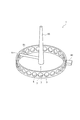
図1及び図2には、本実施形態の軸受用保持器1(以後、単に保持器と呼ぶことがある。)が示されている。保持器1は、いわゆるアンギュラ玉軸受用保持器であり、軸方向に離間した一対の円環部3と、一対の円環部3を連結するように円周方向に所定間隔で配置された奇数個(本実施形態では21個)の柱部5と、一対の円環部3の互いに軸方向に対向する面と隣り合う柱部5の互いに円周方向に対向する面とによって形成され、柱部5と同数(本実施形態では21個)のポケット部7と、を有している。ポケット部7は、軸受の転動体(不図示の玉)を保持する。
(First embodiment)
1 and 2 show a bearing cage 1 (hereinafter, simply referred to as a cage) according to the present embodiment. The
このような保持器1は、成形金型内に形成した環状のキャビティ(不図示)の周縁部に設けた樹脂射出ゲート(以下、単にゲートと呼ぶ。)51から、補強繊維材を添加した溶解樹脂をキャビティ内に射出し、冷却固化することによって成形される。樹脂材料としては、例えば、46ナイロンや66ナイロンなどのポリアミド系樹脂、ポリブチレンテレフタレート、ポリフェニレンサルファイド(PPS)、ポリエーテルエーテルケトン(PEEK)、ポリエーテルニトリル(PEN)等の樹脂に、10〜50wt%の補強繊維材(例えば、ガラス繊維や炭素繊維。)を添加した樹脂組成物が用いられる。なお、図1中、キャビティは不図示であるが、その内部構造は保持器1の構造と略同一とされている。
Such a
ゲート51の個数は特に限定されないが、保持器1の真円度を向上させるためには、複数設けられることが好ましい。本実施形態では、3個のゲート51が設けられる。
The number of
各ゲート51には、それぞれ径方向に延びる略円筒状のランナー53を介して、略円筒状のスプルー55から溶解樹脂が供給される。スプルー55は、保持器1(キャビティ)の略中心において軸方向に延びており、ランナー53と接続される。したがって、スプルー55から供給された溶解樹脂は、各ランナー53を介して各ゲート51に到達し、各ゲート51から同時にキャビティ内に流入する。
Dissolved resin is supplied to each
3個のゲート51は、周方向等間隔にそれぞれ柱部5に設けられる。ここで、隣り合うゲート51の間の第1〜第3領域S1〜S3におけるポケット部7の数は、互いに等しく且つそれぞれ奇数個(本実施形態では7個)である。また、ゲート51は、柱部5の軸方向中央且つ周方向中央に設けられる。
The three
各領域S1〜S3の周方向中央に位置するポケット部7(4番目のポケット部7)に隣り合う一対の柱部5のうち、一方の柱部5には、樹脂溜り40が設けられる。なお、本実施形態では、3つの樹脂溜り40は、各領域S1〜S3の周方向中央に位置するポケット部7に隣り合う一対の柱部5のうち、周方向同一方向側(図1中、反時計回り側)に位置する柱部5に設けられている。これにより、溶解樹脂の流動方向や、樹脂溜り40の跡、ゲート51の跡について、周方向でバランスが良くなり、製造された保持器1も高品質となる。さらに、樹脂溜り40は、柱部5の軸方向中央から軸方向一方側(図中、上側)にずれた位置に連通する。すなわち、ゲート51が柱部5の軸方向中央に設けられるのに対し、樹脂溜り40は柱部5の軸方向中央からずれた位置に設けられており、ゲート51と樹脂溜り40とは互いに軸方向にずれている。
The
図2に示すように、3個のゲート51からキャビティ内に射出された溶解樹脂は、各領域S1〜S3の周方向中央のポケット部7において合流し、複数のウェルド(図中の破線を参照。)が形成される。より具体的に、周方向中央のポケット部7を構成する一対の円環部3には、その周方向中央部に軸方向に延びる円環部ウェルドWaが形成され、当該ポケット部7を構成する一対の柱部5には、その軸方向中央部に周方向に延びる柱部ウェルドWcが形成される。
As shown in FIG. 2, the melted resin injected into the cavity from the three
ここで、当該ポケット部7に隣り合う一対の柱部5のうち、一方の柱部5の軸方向中央からずれた位置には樹脂溜り40が設けられるので、ウェルド形成位置と樹脂溜り配置位置とが周方向及び軸方向にずれ、円環部及び柱部ウェルドWa、Wcと樹脂溜り40との間に溶解樹脂の圧力勾配を生じ易くなる。したがって、図中に矢印で示されるように、当該圧力勾配に起因する強制的な樹脂の流動が起きることで、円環部及び柱部ウェルドWa、Wcにおいて補強繊維材が溶解樹脂の流動方向に対し垂直に配向することを抑制することができる。
Here, since the
なお、各領域S1〜S3における複数の柱部5のうち、周方向においてゲート51に比べて各領域S1〜S3の周方向中央に位置するポケット部7に近い柱部5に、樹脂溜り40が形成される。すなわち、樹脂溜り40と円環部及び柱部ウェルドWa、Wcとの周方向距離は、樹脂溜り40とゲート51との周方向距離よりも短く設定される。さらに、樹脂溜り40と円環部及び柱部ウェルドWa、Wcとの周方向距離は、極力短く設定することが好ましい。すなわち、本実施形態の樹脂溜り40のように、ウェルドが形成されるポケット部7から周方向に数えて一番目の柱部5(ウェルドが形成されるポケット部7に隣り合う柱部5)に設けられることが好ましい。これにより、溶解樹脂が合流した後で、ウェルドにおける強制的な樹脂の流動が起こりやすくなり、ウェルドの補強繊維材の配向が制御されてウェルドの強度が向上する。
Of the plurality of
また、樹脂射出ゲート51や樹脂溜り40が設けられた部位の近傍は、ウェルドが設けられた部位程ではないが、他の部位よりも強度が若干落ちる。しかしながら、本実施形態では、これら樹脂射出ゲート51や樹脂溜り40が、ポケット部7に比べて肉厚が大きい柱部5に配置されているので、保持器1の強度が維持可能である。
In addition, the vicinity of the portion where the
また、本実施形態の保持器1のように、一対の円環部3を有する合成樹脂製保持器の金型は、径方向に可動するラジアルドロー方式が採用されるので、柱部5以外の部位にゲート51や樹脂溜り40を設けることが困難である。したがって、この点からも、ゲート51や樹脂溜り40は柱部5に設けることが好ましい。
Further, as in the
ここで、柱部5と連通し、キャビティへの開口部である樹脂溜り40の連通部42の断面積は、ゲート51の断面積の1/4以下に設定される。これによれば、溶解樹脂が合流してウェルドWが形成された後で樹脂溜り40への溶解樹脂の流入が始まるので、ウェルドWにおける強制的な樹脂の流動によって補強繊維材の配向を制御する効果をより確実に発現することができる。
Here, the cross-sectional area of the
(第2実施形態)
次に、本発明に係る第2実施形態の軸受用保持器の製造方法について図面を参照して説明する。
(Second Embodiment)
Next, the manufacturing method of the bearing retainer according to the second embodiment of the present invention will be described with reference to the drawings.
図3に示すように、本実施形態では、保持器1が、25個の柱部5と、柱部5と同数(25個)のポケット部7と、を有する。また、5個のゲート51及びランナー53が設けられる。
As shown in FIG. 3, in the present embodiment, the
5個のゲート51は、周方向等間隔にそれぞれ柱部5の軸方向中央且つ周方向中央に設けられる。ここで、隣り合うゲート51の間の第1〜第5領域S1〜S5におけるポケット部7の数は、互いに等しく且つそれぞれ奇数個(本実施形態では5個)である。
The five
各領域S1〜S5の周方向中央に位置するポケット部7(3番目のポケット部7)に隣り合う一対の柱部5のうち、一方の柱部5には、樹脂溜り40が設けられる。なお、本実施形態では、5つの樹脂溜り40は、各領域S1〜S5の周方向中央に位置するポケット部7に隣り合う一対の柱部5のうち、周方向同一方向側(図中、反時計回り側)に位置する柱部5に設けられている。
The
本実施形態においても、各領域S1〜S5の周方向中央のポケット部7に隣り合う一対の柱部5のうち、一方の柱部5の軸方向中央からずれた位置に樹脂溜り40が設けられるので、ウェルド形成位置と樹脂溜り配置位置とが周方向及び軸方向にずれ、ウェルドと樹脂溜り40との間に溶解樹脂の圧力勾配を生じ易くなる。したがって、当該圧力勾配に起因する強制的な樹脂の流動が起きることで、ウェルドにおいて補強繊維材が溶解樹脂の流動方向に対し垂直に配向することを抑制することができる。
Also in the present embodiment, the
その他の構成は、上記実施形態と同様であり、上記実施形態と同様の効果を奏することが可能である。 Other configurations are the same as those in the above embodiment, and the same effects as those in the above embodiment can be obtained.
(第3実施形態)
次に、本発明に係る第3実施形態の軸受用保持器の製造方法について図面を参照して説明する。
(Third embodiment)
Next, the manufacturing method of the bearing retainer of 3rd Embodiment which concerns on this invention is demonstrated with reference to drawings.
図3に示すように、本実施形態の保持器1は、第2実施形態の保持器1と同様の構成を有する。すなわち、保持器1は、25個の柱部5と、柱部5と同数(25個)のポケット部7と、を有する。
As shown in FIG. 3, the
ゲート51及びランナー53はそれぞれ1個のみ設けられる。ゲート51は、柱部5の軸方向中央且つ周方向中央に設けられる。ゲート51と径方向に対向するポケット部7(ゲート51が設けられる位置を基準に13番目のポケット部7)に隣り合う一対の柱部5のうち、一方の柱部5には、樹脂溜り40が設けられる。
Only one
1個のゲート51からキャビティ内に射出された溶解樹脂は、ゲート51と径方向に対向するポケット部7において合流し、複数のウェルド(図2参照)が形成される。ここで、当該ポケット部7に隣り合う一対の柱部5のうち、一方の柱部5の軸方向中央からずれた位置には樹脂溜り40が設けられるので、ウェルド形成位置と樹脂溜り配置位置とが周方向及び軸方向にずれ、ウェルドと樹脂溜り40との間に溶解樹脂の圧力勾配を生じ易くなる。したがって、当該圧力勾配に起因する強制的な樹脂の流動が起きることで、ウェルドにおいて補強繊維材が溶解樹脂の流動方向に対し垂直に配向することを抑制することができる。
The melted resin injected into the cavity from one
なお、複数の柱部5のうち、周方向においてゲート51に比べて当該ゲート51と径方向に対向するポケット部7に近い柱部5に、樹脂溜り40が形成される。すなわち、樹脂溜り40とウェルドとの周方向距離は、樹脂溜り40とゲート51との周方向距離よりも短く設定される。さらに、樹脂溜り40とウェルドとの周方向距離は、極力短く設定することが好ましい。すなわち、本実施形態の樹脂溜り40のように、ウェルドが形成されるポケット部7(ゲート51と径方向に対向するポケット部7)から周方向に数えて一番目の柱部5(ウェルドが形成されるポケット部7に隣り合う柱部5)に設けられることが好ましい。これにより、溶解樹脂が合流した後で、ウェルドにおける強制的な樹脂の流動が起こりやすくなり、ウェルドの補強繊維材の配向が制御されてウェルドの強度が向上する。
Of the plurality of
その他の構成は、上記実施形態と同様であり、上記実施形態と同様の効果を奏することが可能である。 Other configurations are the same as those in the above embodiment, and the same effects as those in the above embodiment can be obtained.
(第4実施形態)
次に、本発明に係る第4実施形態の軸受用保持器の製造方法について図面を参照して説明する。
(Fourth embodiment)
Next, a method for manufacturing a bearing cage according to a fourth embodiment of the present invention will be described with reference to the drawings.
図5及び図6に示すように、本実施形態では、ゲート51が、柱部5の軸方向中央からずれた位置に設けられる点で、第1実施形態(図1及び図2参照)と相違する。ゲート51は、柱部5の軸方向中央から軸方向一方側(図中上側)にずれた位置に設けられ、樹脂溜り40は、柱部5の軸方向中央からゲート51と同じ方向(軸方向一方側)にずれた位置に設けられる。
As shown in FIGS. 5 and 6, this embodiment is different from the first embodiment (see FIGS. 1 and 2) in that the
図6に示すように、3個のゲート51からキャビティ内に射出された溶解樹脂は、各領域S1〜S3の周方向中央のポケット部7において合流し、複数のウェルド(図中の点線を参照。)が形成される。より具体的に、各領域S1〜S3の周方向中央のポケット部7を構成する一対の円環部3には、その周方向中央部に軸方向に延びる円環部ウェルドWaが形成される。また、保持器1には、さらに他の一対の円環部ウェルドWbが形成される。円環部ウェルドWbの一端は、保持器1の軸方向他方側端部(図中の下方側端部)で、各領域S1〜S3の周方向中央のポケット部7を構成する柱部5と周方向において重なる部分に位置する。円環部ウェルドWbの他端は、各領域S1〜S3の周方向中央のポケット部7に隣り合うポケット部7の軸方向他方側部(図中の下方部)で、各領域S1〜S3の周方向中央のポケット部7に近い側の部分に位置する。そして、円環部ウェルドWbは、上記一端及び他端を結ぶように、各領域S1〜S3の周方向中央のポケット部7から周方向において離れるにしたがって軸方向一方側(図中、上方側)に延びる。
As shown in FIG. 6, the melted resin injected into the cavity from the three
ここで、当該ポケット部7に隣り合う一対の柱部5のうち、一方の柱部5の軸方向中央から軸方向一方側にずれた位置には樹脂溜り40が設けられるので、ウェルド形成位置と樹脂溜り配置位置とが周方向及び軸方向にずれ、円環部ウェルドWa、Wbと樹脂溜り40との間に溶解樹脂の圧力勾配を生じ易くなる。したがって、図中に矢印で示されるように、当該圧力勾配に起因する強制的な樹脂の流動が起きることで、円環部ウェルドWa、Wbにおいて補強繊維材が溶解樹脂の流動方向に対し垂直に配向することを抑制することができる。
Here, since the
その他の構成は、第1実施形態と同様であり、第1実施形態と同様の効果を奏することが可能である。 Other configurations are the same as those of the first embodiment, and the same effects as those of the first embodiment can be obtained.
(第5実施形態)
次に、本発明に係る第5実施形態の軸受用保持器の製造方法について図面を参照して説明する。
(Fifth embodiment)
Next, the manufacturing method of the bearing retainer of 5th Embodiment which concerns on this invention is demonstrated with reference to drawings.
図7に示すように、本実施形態の保持器1は、第2及び第3実施形態の保持器1と同様の構成を有する。すなわち、保持器1は、25個の柱部5と、柱部5と同数(25個)のポケット部7と、を有する。
As shown in FIG. 7, the
また、5個のゲート51及びランナー53が設けられる。5個のゲート51は、周方向等間隔にそれぞれ柱部5の軸方向中央から軸方向一方側(図中上側)にずれた位置且つ周方向中央に設けられる。ここで、隣り合うゲート51の間の第1〜第5領域S1〜S5におけるポケット部7の数は、互いに等しく且つそれぞれ奇数個(本実施形態では5個)である。
Further, five
各領域S1〜S5の周方向中央に位置するポケット部7(3番目のポケット部7)に隣り合う一対の柱部5のうち、一方の柱部5には、樹脂溜り40が設けられる。なお、本実施形態では、5つの樹脂溜り40は、各領域S1〜S5の周方向中央に位置するポケット部7に隣り合う一対の柱部5のうち、周方向同一方向側(図中、反時計回り側)に位置する柱部5に設けられている。樹脂溜り40は、柱部5の軸方向中央からゲート51と同じ方向(軸方向一方側)にずれた位置に設けられる。
The
本実施形態においても、各領域S1〜S5の周方向中央のポケット部7に隣り合う一対の柱部5のうち、一方の柱部5の軸方向中央から軸方向一方側にずれた位置には樹脂溜り40が設けられるので、ウェルド形成位置と樹脂溜り40配置位置とが周方向及び軸方向にずれ、ウェルドと樹脂溜り40との間に溶解樹脂の圧力勾配を生じ易くなる。したがって、当該圧力勾配に起因する強制的な樹脂の流動が起きることで、ウェルドにおいて補強繊維材が溶解樹脂の流動方向に対し垂直に配向することを抑制することができる。
Also in the present embodiment, of the pair of
その他の構成は、第4実施形態と同様であり、上記実施形態と同様の効果を奏することが可能である。 Other configurations are the same as those of the fourth embodiment, and the same effects as those of the above-described embodiment can be obtained.
(第6実施形態)
次に、本発明に係る第6実施形態の軸受用保持器の製造方法について図面を参照して説明する。
(Sixth embodiment)
Next, a bearing cage manufacturing method according to a sixth embodiment of the present invention will be described with reference to the drawings.
図8に示すように、本実施形態の保持器1は、第2、第3、及び第5実施形態の保持器1と同様の構成を有する。すなわち、保持器1は、25個の柱部5と、柱部5と同数(25個)のポケット部7と、を有する。
As shown in FIG. 8, the
ゲート51及びランナー53は1個のみ設けられる。ゲート51は、柱部5の軸方向中央から軸方向一方側(図中上側)にずれた位置且つ周方向中央に設けられる。ゲート51と対向するポケット部7に隣り合う一対の柱部5のうち、一方の柱部5には、樹脂溜り40が設けられる。樹脂溜り40は、柱部5の軸方向中央からゲート51と同じ方向(軸方向一方側)にずれた位置に設けられる。
Only one
1個のゲート51からキャビティ内に射出された溶解樹脂は、ゲート51と対向するポケット部7において合流し、複数のウェルド(図6参照)が形成される。ここで、当該ポケット部7に隣り合う一対の柱部5のうち、一方の柱部5の軸方向中央からずれた位置には樹脂溜り40が設けられるので、ウェルド形成位置と樹脂溜り40配置位置とが周方向及び軸方向にずれ、ウェルドと樹脂溜り40との間に溶解樹脂の圧力勾配を生じ易くなる。したがって、当該圧力勾配に起因する強制的な樹脂の流動が起きることで、ウェルドにおいて補強繊維材が溶解樹脂の流動方向に対し垂直に配向することを抑制することができる。
The molten resin injected into the cavity from one
なお、複数の柱部5のうち、周方向においてゲート51に比べて当該ゲート51と径方向に対向するポケット部7に近い柱部5に、樹脂溜り40が形成される。すなわち、樹脂溜り40とウェルドとの周方向距離は、樹脂溜り40とゲート51との周方向距離よりも短く設定される。さらに、樹脂溜り40とウェルドとの周方向距離は、極力短く設定することが好ましい。すなわち、本実施形態の樹脂溜り40のように、ウェルドが形成されるポケット部7(ゲート51と径方向に対向するポケット部7)から周方向に数えて一番目の柱部5(ウェルドが形成されるポケット部7に隣り合う柱部5)に設けられることが好ましい。これにより、溶解樹脂が合流した後で、ウェルドにおける強制的な樹脂の流動が起こりやすくなり、ウェルドの補強繊維材の配向が制御されてウェルドの強度が向上する。
Of the plurality of
その他の構成は、第5実施形態と同様であり、第5実施形態と同様の効果を奏することが可能である。 Other configurations are the same as those of the fifth embodiment, and the same effects as those of the fifth embodiment can be obtained.
(実施例)
次に、樹脂溜り40の連通部42の断面積と、樹脂射出ゲート51の断面積と、の関係についての解析結果について述べる。
(Example)
Next, the analysis result about the relationship between the cross-sectional area of the
図9〜12及び表1に示すように実施例1及び比較例1〜3において、キャビティ60を簡単な単純円環モデルとし、樹脂射出ゲート51の径(断面積)を一定とし、樹脂溜り40の連通部42の径(断面積)を変化させたときの、溶解樹脂Gが流動する様子を、東レエンジニアリング(株)製の樹脂流動解析ソフトウェア「3D TIMON」にて解析した。
9 to 12 and Table 1, in Example 1 and Comparative Examples 1 to 3, the

図10〜12の比較例1〜3に示すように、樹脂射出ゲート51の断面積に対する連通部42の断面積の比率が0.44〜1.00のときは、溶解樹脂G同士が合流する前に樹脂溜り40への溶解樹脂Gの流入が始まる。これらの場合、溶解樹脂Gが合流した後でウェルドWに強制的な樹脂の流動を起こす効果が小さく、ウェルドWにおける補強繊維材の配向を制御する効果が発現しにくい。
As shown in Comparative Examples 1 to 3 in FIGS. 10 to 12, when the ratio of the cross-sectional area of the
一方、図9の実施例1に示すように、樹脂射出ゲート51の断面積に対する連通部42の断面積の比率が0.25のときは、溶解樹脂Gが合流する前には、樹脂溜り40に溶解樹脂Gが流入しない。このため、溶解樹脂Gが合流してウェルドWが形成された後で、ウェルドWに強制的な樹脂の流動を起こす効果が大きく、ウェルドWにおける補強繊維材の配向を制御する効果を発現する。
On the other hand, when the ratio of the cross-sectional area of the
このように、樹脂溜り40の連通部42の断面積が、樹脂射出ゲート51の断面積の1/4以下である場合、溶解樹脂Gが合流する前には樹脂溜り40に溶解樹脂Gが流入せず、ウェルドWにおける補強繊維材の配向を制御する効果を発現することが明らかとなった。
Thus, when the cross-sectional area of the
尚、本発明は、前述した各実施形態に限定されるものではなく、適宜、変形、改良、等が可能である。 In addition, this invention is not limited to each embodiment mentioned above, A deformation | transformation, improvement, etc. are possible suitably.
例えば、本発明の製造方法が適用される保持器は、アンギュラ玉軸受用保持器に限定されず、円筒ころ軸受用保持器や円錐ころ軸受用保持器等、様々な種類の保持器に適用可能である。 For example, the cage to which the manufacturing method of the present invention is applied is not limited to the angular ball bearing cage, and can be applied to various types of cages such as a cylindrical roller bearing cage and a tapered roller bearing cage. It is.
また、本発明の軸受用保持器は、強度低下が少なく耐久性に優れるため、転がり軸受に適用することが好適である。すなわち、このような転がり軸受は、内輪と、外輪と、内輪及び外輪との間に設けられた複数の転動体と、転動体をポケットに転動自在に保持し、耐久性に優れる軸受用保持器と、を備えるので、高速回転や高負荷等の要求を満たすことが可能である。 In addition, the bearing cage of the present invention is suitable for rolling bearings because it is less durable and excellent in durability. That is, such a rolling bearing has an inner ring, an outer ring, a plurality of rolling elements provided between the inner ring and the outer ring, and the rolling element is held in a pocket so that the rolling element can roll freely, and has excellent durability. Can satisfy the requirements such as high-speed rotation and high load.
1 軸受用保持器
3 円環部
5 柱部
7 ポケット部
40 樹脂溜り
42 連通部
51 樹脂射出ゲート
53 ランナー
55 スプルー
60 キャビティ
S1〜S5 第1〜第5領域
Wa、Wb 円環部ウェルド
Wc 柱部ウェルド
DESCRIPTION OF
Claims (3)
前記軸受用保持器は、
軸方向に離間した一対の円環部と、
一対の前記円環部を連結するように、円周方向に所定間隔で配置された奇数個の柱部と、
一対の前記円環部の互いに対向する面と、隣り合う前記柱部の互いに対向する面と、によって形成された、前記柱部と同数のポケット部と、
を有し、
前記樹脂射出ゲートは、前記柱部に設けられ、
複数の前記柱部のうち、周方向において前記樹脂射出ゲートと比べて該樹脂射出ゲートと対向するポケット部に近い前記柱部の、軸方向中央からずれた位置に、前記溶解樹脂を貯留可能な樹脂溜りが設けられ、
前記柱部と連通する前記樹脂溜りの連通部の断面積は、前記樹脂射出ゲートの断面積の1/4以下である、ことを特徴とする軸受用保持器の製造方法。 A method of manufacturing a bearing retainer that is molded by injecting a molten resin into a cavity from a single resin injection gate provided at the peripheral edge of a substantially annular cavity formed in a molding die. And
The bearing cage is
A pair of annular portions spaced apart in the axial direction;
An odd number of pillars arranged at predetermined intervals in the circumferential direction so as to connect the pair of ring parts;
A plurality of pocket portions equal to the number of the pillar portions formed by the mutually facing surfaces of the pair of annular portions and the mutually facing surfaces of the adjacent pillar portions;
Have
The resin injection gate is provided on the pillar portion,
Among the plurality of column portions, the molten resin can be stored at a position shifted from the axial center of the column portion close to the pocket portion facing the resin injection gate in the circumferential direction compared to the resin injection gate. A resin reservoir is provided,
The method of manufacturing a bearing retainer, wherein a cross-sectional area of the communication portion of the resin reservoir communicating with the column portion is ¼ or less of a cross-sectional area of the resin injection gate.
前記軸受用保持器は、
軸方向に離間した一対の円環部と、
一対の前記円環部を連結するように、円周方向に所定間隔で配置された奇数個の柱部と、
一対の前記円環部の互いに対向する面と、隣り合う前記柱部の互いに対向する面と、によって形成された、前記柱部と同数のポケット部と、
を有し、
隣り合う前記樹脂射出ゲートの間の領域における前記ポケット部の数が互いに等しく且つそれぞれ奇数個となるように、複数の前記樹脂射出ゲートはそれぞれ前記柱部に設けられ、
前記領域における複数の前記柱部のうち、周方向において前記樹脂射出ゲートに比べて前記領域の周方向中央に位置するポケット部に近い柱部の、軸方向中央からずれた位置に、前記溶解樹脂を貯留可能な樹脂溜りが設けられ、
前記柱部と連通する前記樹脂溜りの連通部の断面積は、前記樹脂射出ゲートの断面積の1/4以下である、ことを特徴とする軸受用保持器の製造方法。 A method for manufacturing a bearing retainer that is molded by injecting molten resin into a cavity from a plurality of resin injection gates provided at a peripheral edge of a substantially annular cavity formed in a molding die. ,
The bearing cage is
A pair of annular portions spaced apart in the axial direction;
An odd number of pillars arranged at predetermined intervals in the circumferential direction so as to connect the pair of ring parts;
A plurality of pocket portions equal to the number of the pillar portions formed by the mutually facing surfaces of the pair of annular portions and the mutually facing surfaces of the adjacent pillar portions;
Have
A plurality of the resin injection gates are respectively provided in the pillar portions so that the number of the pocket portions in the region between the adjacent resin injection gates is equal to each other and an odd number.
Among the plurality of column portions in the region, the molten resin is located at a position shifted from the axial center of a column portion close to the pocket portion located in the circumferential center of the region in the circumferential direction compared to the resin injection gate. Is provided with a resin reservoir,
The method of manufacturing a bearing retainer, wherein a cross-sectional area of the communication portion of the resin reservoir communicating with the column portion is ¼ or less of a cross-sectional area of the resin injection gate.
前記樹脂溜りは、前記柱部の軸方向中央から前記樹脂射出ゲートと同じ方向にずれた位置に設けられる、ことを特徴とする請求項1又は2に記載の軸受用保持器の製造方法。 The resin injection gate is provided at a position shifted from the axial center of the column part,
The method for manufacturing a bearing retainer according to claim 1, wherein the resin reservoir is provided at a position shifted from the axial center of the column portion in the same direction as the resin injection gate.
Priority Applications (1)
| Application Number | Priority Date | Filing Date | Title |
|---|---|---|---|
| JP2015173675A JP6578827B2 (en) | 2015-09-03 | 2015-09-03 | Manufacturing method of bearing cage |
Applications Claiming Priority (1)
| Application Number | Priority Date | Filing Date | Title |
|---|---|---|---|
| JP2015173675A JP6578827B2 (en) | 2015-09-03 | 2015-09-03 | Manufacturing method of bearing cage |
Publications (3)
| Publication Number | Publication Date |
|---|---|
| JP2017048873A JP2017048873A (en) | 2017-03-09 |
| JP2017048873A5 JP2017048873A5 (en) | 2018-09-20 |
| JP6578827B2 true JP6578827B2 (en) | 2019-09-25 |
Family
ID=58280005
Family Applications (1)
| Application Number | Title | Priority Date | Filing Date |
|---|---|---|---|
| JP2015173675A Active JP6578827B2 (en) | 2015-09-03 | 2015-09-03 | Manufacturing method of bearing cage |
Country Status (1)
| Country | Link |
|---|---|
| JP (1) | JP6578827B2 (en) |
Families Citing this family (1)
| Publication number | Priority date | Publication date | Assignee | Title |
|---|---|---|---|---|
| JP7396790B2 (en) * | 2018-08-10 | 2023-12-12 | 日本精工株式会社 | Manufacturing method for cages for rolling bearings |
Family Cites Families (5)
| Publication number | Priority date | Publication date | Assignee | Title |
|---|---|---|---|---|
| JPS5988514U (en) * | 1982-12-06 | 1984-06-15 | 日本精工株式会社 | Cage for rolling bearings |
| JP5768486B2 (en) * | 2011-05-12 | 2015-08-26 | 日本精工株式会社 | Resin cage for bearing and method for manufacturing the same |
| JP6413728B2 (en) * | 2014-12-11 | 2018-10-31 | 日本精工株式会社 | Manufacturing method of bearing cage |
| JP6405973B2 (en) * | 2014-12-11 | 2018-10-17 | 日本精工株式会社 | Manufacturing method of bearing cage |
| JP6413729B2 (en) * | 2014-12-11 | 2018-10-31 | 日本精工株式会社 | Manufacturing method of bearing cage |
-
2015
- 2015-09-03 JP JP2015173675A patent/JP6578827B2/en active Active
Also Published As
| Publication number | Publication date |
|---|---|
| JP2017048873A (en) | 2017-03-09 |
Similar Documents
| Publication | Publication Date | Title |
|---|---|---|
| JP5768486B2 (en) | Resin cage for bearing and method for manufacturing the same | |
| JP6222146B2 (en) | Manufacturing method of bearing cage | |
| JP6405973B2 (en) | Manufacturing method of bearing cage | |
| JP6575672B2 (en) | Manufacturing method of bearing cage and bearing cage | |
| JP6772587B2 (en) | Manufacturing method of synthetic resin cage and synthetic resin cage | |
| JP6413728B2 (en) | Manufacturing method of bearing cage | |
| JP2013046982A (en) | Manufacturing method of annular resin product, resin retainer for rolling bearing, rolling bearing, and mold | |
| JP6413729B2 (en) | Manufacturing method of bearing cage | |
| JP6578827B2 (en) | Manufacturing method of bearing cage | |
| JP6299529B2 (en) | Bearing cage and manufacturing method thereof | |
| JP6405974B2 (en) | Manufacturing method of bearing cage | |
| JP6413730B2 (en) | Manufacturing method of bearing cage | |
| JP6451190B2 (en) | Manufacturing method of bearing cage | |
| JP6471813B2 (en) | Bearing cage | |
| JP6988509B2 (en) | Manufacturing method of bearing cage | |
| JP6699698B2 (en) | Bearing cage | |
| JP2016080050A (en) | Resin holder for bearing and manufacturing method thereof | |
| JP6658841B2 (en) | Bearing cage | |
| JP2019011865A (en) | Retainer for bearing | |
| JP6658840B2 (en) | Bearing cage | |
| JP6702384B2 (en) | Bearing cage | |
| JP2015075201A (en) | Resin-made cage for bearing and manufacturing method thereof | |
| JP6658053B2 (en) | Synthetic resin cage for rolling bearings |
Legal Events
| Date | Code | Title | Description |
|---|---|---|---|
| A521 | Written amendment |
Free format text: JAPANESE INTERMEDIATE CODE: A523 Effective date: 20180810 |
|
| A621 | Written request for application examination |
Free format text: JAPANESE INTERMEDIATE CODE: A621 Effective date: 20180810 |
|
| A977 | Report on retrieval |
Free format text: JAPANESE INTERMEDIATE CODE: A971007 Effective date: 20190719 |
|
| TRDD | Decision of grant or rejection written | ||
| A01 | Written decision to grant a patent or to grant a registration (utility model) |
Free format text: JAPANESE INTERMEDIATE CODE: A01 Effective date: 20190730 |
|
| A61 | First payment of annual fees (during grant procedure) |
Free format text: JAPANESE INTERMEDIATE CODE: A61 Effective date: 20190812 |
|
| R150 | Certificate of patent or registration of utility model |
Ref document number: 6578827 Country of ref document: JP Free format text: JAPANESE INTERMEDIATE CODE: R150 |