JP6576740B2 - Coil bobbin, coil and transformer provided with the coil - Google Patents
Coil bobbin, coil and transformer provided with the coil Download PDFInfo
- Publication number
- JP6576740B2 JP6576740B2 JP2015164715A JP2015164715A JP6576740B2 JP 6576740 B2 JP6576740 B2 JP 6576740B2 JP 2015164715 A JP2015164715 A JP 2015164715A JP 2015164715 A JP2015164715 A JP 2015164715A JP 6576740 B2 JP6576740 B2 JP 6576740B2
- Authority
- JP
- Japan
- Prior art keywords
- winding
- coil
- groove
- concave groove
- bobbin
- Prior art date
- Legal status (The legal status is an assumption and is not a legal conclusion. Google has not performed a legal analysis and makes no representation as to the accuracy of the status listed.)
- Active
Links
- 238000004804 winding Methods 0.000 claims description 754
- 230000002093 peripheral effect Effects 0.000 claims description 35
- 230000006698 induction Effects 0.000 claims description 3
- 239000010410 layer Substances 0.000 description 129
- WABPQHHGFIMREM-UHFFFAOYSA-N lead(0) Chemical compound [Pb] WABPQHHGFIMREM-UHFFFAOYSA-N 0.000 description 29
- XEEYBQQBJWHFJM-UHFFFAOYSA-N Iron Chemical group [Fe] XEEYBQQBJWHFJM-UHFFFAOYSA-N 0.000 description 12
- 238000000034 method Methods 0.000 description 9
- 238000009826 distribution Methods 0.000 description 7
- 238000009413 insulation Methods 0.000 description 7
- 230000000694 effects Effects 0.000 description 6
- 238000004519 manufacturing process Methods 0.000 description 6
- 238000000465 moulding Methods 0.000 description 3
- 239000011347 resin Substances 0.000 description 3
- 229920005989 resin Polymers 0.000 description 3
- 230000015556 catabolic process Effects 0.000 description 2
- 238000001816 cooling Methods 0.000 description 2
- 238000010586 diagram Methods 0.000 description 2
- 239000011229 interlayer Substances 0.000 description 2
- 238000003475 lamination Methods 0.000 description 2
- 238000000605 extraction Methods 0.000 description 1
- 230000004048 modification Effects 0.000 description 1
- 238000012986 modification Methods 0.000 description 1
- 230000010355 oscillation Effects 0.000 description 1
- 230000000630 rising effect Effects 0.000 description 1
- 239000002356 single layer Substances 0.000 description 1
- 230000003068 static effect Effects 0.000 description 1
- 230000009466 transformation Effects 0.000 description 1
- 238000009827 uniform distribution Methods 0.000 description 1
Images


Landscapes
- Coils Of Transformers For General Uses (AREA)
- Insulating Of Coils (AREA)
Description
本発明は、巻線が整列巻きされるコイルボビン、そのコイルボビンに巻線を巻回したコイル及びそのコイルを備えた変圧器に関するものである。 The present invention relates to a coil bobbin in which windings are aligned and wound, a coil in which a winding is wound around the coil bobbin, and a transformer including the coil.
従来、変圧器用のコイルに用いられるコイルボビンとして、長方形のリング形状を有する枠体から成り、その枠体の外周側の側面(以下、「外周側面」という。)に巻線を巻回するための凹溝が形成されたコイルボビンが知られている。例えば、特許文献1の図6には、一次コイル用のコイルボビンとして、長方形のリング形状を有する枠体の外周側面に、底面側が先窄まりとなるように両内壁面を傾斜させた断面形状を有する凹溝を設けたコイルボビンが記載されている。
Conventionally, as a coil bobbin used for a coil for a transformer, it is composed of a frame having a rectangular ring shape, and a winding is wound around a side surface on the outer peripheral side of the frame (hereinafter referred to as “outer peripheral side surface”). A coil bobbin in which a concave groove is formed is known. For example, in FIG. 6 of
同図に記載のコイルボビンは、枠体の長辺の部分に円筒状の鉄心を装着するために、当該枠体の内周側の側面(以下、「内周側面」という。)の形状が円弧状に成形されている。また、枠体の短辺の部分にコイルボビンの凹溝に巻回された一次巻線の両端部をコイルボビン外に引き出すための切り欠きが設けられている。 The coil bobbin shown in the figure has a circular inner core side surface (hereinafter referred to as “inner peripheral side surface”) in order to mount a cylindrical iron core on the long side portion of the frame. It is formed in an arc shape. Moreover, the notch for drawing out the both ends of the primary winding wound by the groove of the coil bobbin to the outside of a coil bobbin is provided in the short side part of the frame.
特許文献1の図6に記載のコイルボビンでは、一次巻線の一方端部を切り欠きからコイルボビンの外部に引き出した状態で凹溝の底面の幅方向の一方端(切り欠きのある端)から他方端まで隙間なく巻回した(整列巻きした)後に折り返して先に整列巻きした一次巻線の上側に他方端から一方端まで隙間なく巻回する整列巻き動作を所定の回数だけ繰り返した後、一次巻線の他方端部を切り欠きからコイルボビンの外部に引き出して、所定のターン数を有する一次コイルが製作される。
In the coil bobbin described in FIG. 6 of
そして、コイルボビンの切り欠きから引き出された一次巻線の両端部は、コイルボビンの外部に設けられる一対の一次ブッシング(変圧器の一次電圧が印加されるブッシング)にそれぞれ接続される。 Then, both end portions of the primary winding drawn out from the notch of the coil bobbin are respectively connected to a pair of primary bushings (bushings to which the primary voltage of the transformer is applied) provided outside the coil bobbin.
例えば、配電用6600[V]/(210−105[V]変圧器では、一次コイルに6000[V]以上の高圧が印加されるので、コイルボビンに一次巻線を整列巻きする場合、上下左右に隣接する巻線同士の電位差を考慮して巻線同士の絶縁をする必要がある。特に、コイルボビンから引き出される一次巻線の両端間には6000[V]以上の高圧が印加されるので、積層された一次巻線でも高圧が印加される端部側の積層された巻線同士の電位差を十分に考慮する必要がある。 For example, in a 6600 [V] / (210-105 [V] transformer for power distribution, a high voltage of 6000 [V] or more is applied to the primary coil. It is necessary to insulate the windings in consideration of the potential difference between adjacent windings, especially since a high voltage of 6000 [V] or more is applied between both ends of the primary winding drawn from the coil bobbin. It is necessary to sufficiently consider the potential difference between the stacked windings on the end side to which a high voltage is applied even in the primary winding.
例えば、コイルボビンの凹溝の整列巻きされる一次巻線の両端間に6600[V]の高圧が印加される場合、一次巻線の凹溝への巻回が開始される位置(高圧が印加される1層目の巻線の巻回開始位置)の電圧v1は6000[V]以上の高圧となる。凹溝の幅方向に一往復するように整列巻きされて1層目の巻線の上側に積層された2層目の巻線の先端部の電圧vaは、一次巻線の全巻数をT[ターン]、1層目の巻線開始位置から2層目の巻線終端位置までの巻数をΔT[ターン]とすると、va=(1−ΔT/T)×全電圧(6600[V]となる。 For example, when a high voltage of 6600 [V] is applied between both ends of the primary winding to be aligned and wound in the groove of the coil bobbin, the position where the winding of the primary winding into the groove is started (the high voltage is applied). that the voltage v 1 of the winding start position) of the first layer of the winding becomes 6000 [V] or more high pressure. First voltage v a of the distal end portion of the second layer of windings stacked on the upper side of the regular winding has been first layer of windings as reciprocating in the width direction of the groove, T the number whole set of the primary winding [Turn] When the number of turns from the first layer winding start position to the second layer winding end position is ΔT [turn], v a = (1−ΔT / T) × total voltage (6600 [V]) It becomes.
一次巻線の巻回開始位置における上下に隣接する巻線同士の電位差は誘起電圧差分Δv=v1−va=(ΔT/T)×全電圧となる。凹溝の幅方向に一往復するように整列巻きされる巻線のターン数が多いと、すなわち、溝の幅方向のサイズが大きいと、巻線が一往復する分のターン数の全巻数に対する割合(ΔT/T)が大きくなり、その間の誘起電圧Δvが増大する。 The potential difference between the windings adjacent to each other vertically in the winding start position of the primary winding becomes the induced voltage difference Δv = v 1 -v a = ( ΔT / T) × total voltage. When the number of turns of the winding wound in a row so as to make one reciprocation in the width direction of the concave groove is large, that is, when the size in the width direction of the groove is large, the number of turns for one reciprocation of the winding corresponds to the total number of turns. The ratio (ΔT / T) increases, and the induced voltage Δv during that time increases.
積層される一次巻線の層間の絶縁が十分でない場合、6000[V]以上の高圧が印加される巻線の端部で絶縁破壊が生じると、変圧器が故障するばかりでなく、大事故に繋がる恐れがある。従って、通常は、積層される一次巻線の層間に絶縁シートなどを介在させるなどの対策が施される。 If insulation between the layers of the laminated primary windings is not sufficient, if a dielectric breakdown occurs at the end of the winding to which a high voltage of 6000 [V] or more is applied, not only will the transformer fail, but a major accident may occur. There is a risk of being connected. Therefore, usually, countermeasures such as interposing an insulating sheet or the like between layers of the laminated primary windings are taken.
しかしながら、積層される一次巻線の層間に絶縁シートなどを介在させると、その分、一次巻線を整列巻きする凹溝の深さを深くする必要があり、コイルボビンが大型化するという問題がある。また、巻線以外に絶縁シートなどの部品が必要になり、コイルのコストを増大させるという問題もある。 However, if an insulating sheet or the like is interposed between the layers of the primary windings to be laminated, it is necessary to increase the depth of the concave grooves for aligning and winding the primary windings, and the coil bobbin becomes large. . In addition to the winding, a part such as an insulating sheet is required, which increases the cost of the coil.
本発明は、上記の課題に鑑みてなされたものであり、積層される巻線の一層当たりの巻数を低減して層間の耐電圧を抑制することができるコイルボビン、そのコイルボビンに巻線を巻回したコイル及びそのコイルを備えた変圧器を提供することを目的とする。 The present invention has been made in view of the above problems, and a coil bobbin capable of suppressing the withstand voltage between layers by reducing the number of turns per layer of the laminated windings, and winding the winding around the coil bobbin It is an object of the present invention to provide a coil and a transformer including the coil.
第一の発明のコイルボビンは、ボビン本体と、ボビン本体の外周側面に形成された凹溝とを備え、凹溝に巻線を層状に整列巻きしてコイルが製作されるコイルボビンであって、凹溝の底面に、当該凹溝を幅方向に分割する少なくとも1の分割壁が形成されていることを特徴とするコイルボビンである。 A coil bobbin according to a first aspect of the present invention is a coil bobbin including a bobbin main body and a concave groove formed on an outer peripheral side surface of the bobbin main body, and a coil is manufactured by winding the windings in layers in the concave groove. The coil bobbin is characterized in that at least one dividing wall for dividing the concave groove in the width direction is formed on the bottom surface of the groove.
上記のコイルボビンの好ましい実施の形態として、凹溝の底面に、巻線の巻き付け位置をガイドするガイド溝が形成されているとよい。 As a preferred embodiment of the coil bobbin, a guide groove for guiding the winding position of the winding may be formed on the bottom surface of the concave groove.
また、上記のコイルボビンの好ましい実施の形態として、凹溝の横断面形状は、矩形若しくは上底が下底よりも長く、下底の両端の内角が120°である等脚台形であるとよい。 As a preferred embodiment of the above-described coil bobbin, the cross-sectional shape of the groove is preferably a rectangular or an isosceles trapezoid whose upper base is longer than the lower base and whose inner angles at both ends of the lower base are 120 °.
また、上記のコイルボビンの好ましい実施の形態として、巻線は、巻数の主要部を構成する主要巻線と、巻数の調整部を構成する巻数調整用巻線とを有しており、凹溝は、所定の断面形状を有する第1の凹溝と、当該第1の凹溝に底面側若しくは開口面側に延設された、所定の断面形状を有する第2の凹溝とを有しており、巻線は、主要巻線が第1の凹溝に層状に整列巻きされ、巻数調整用巻線は、第2の凹溝に層状に整列巻きされるとよい。 Further, as a preferred embodiment of the above-described coil bobbin, the winding has a main winding constituting the main part of the number of turns and a winding adjusting coil constituting the adjustment part of the number of turns. A first groove having a predetermined cross-sectional shape, and a second groove having a predetermined cross-sectional shape extending to the bottom surface side or the opening surface side of the first groove. The winding may be arranged such that the main winding is aligned and wound in layers in the first concave groove, and the winding number adjusting winding is aligned and wound in layers in the second concave groove.
また、上記のコイルボビンの好ましい実施の形態として、第2の凹溝は、第1の凹溝の底面に穿設されており、第2の凹溝の底面には、当該第2の凹溝と第1の凹溝を幅方向に第1の空間と第2の空間に分割するように、1つの分割壁が垂直に形成されており、第2の凹溝の第1の空間に臨む側壁には、巻数調整用巻線の両端部をボビン本体から引き出すための第1の巻線引出部が設けられており、第1の凹溝の両側壁には、主要巻線の両端部をそれぞれボビン本体から引き出すための第2の巻線引出部が設けられており、巻線は、巻数調整用巻線が第2の凹溝の第1の空間に層状に整列巻きされた後、主要巻線が第1の凹溝の第1の空間と第2の空間に亘って層状に整列巻きされ、第1の巻線引出部から引き出された巻数調整用巻線の一方端と第2の巻線引出部から引き出された主要巻線の一方端とがボビン本体の外部でタップ端子を介して直列に接続されるとよい。 As a preferred embodiment of the above-described coil bobbin, the second groove is formed in the bottom surface of the first groove, and the second groove is formed on the bottom surface of the second groove. One dividing wall is formed vertically so as to divide the first groove into the first space and the second space in the width direction, and on the side wall facing the first space of the second groove. Is provided with first winding lead portions for pulling out both end portions of the winding number adjusting winding from the bobbin body, and both end portions of the main winding are respectively disposed on both side walls of the first concave groove. A second winding lead portion for pulling out from the main body is provided, and the winding is arranged after the winding number adjusting winding is aligned and wound in layers in the first space of the second concave groove, and then the main winding. Is one of the windings for adjusting the number of turns that is wound in a layered manner over the first space and the second space of the first groove and is drawn from the first winding lead portion. When good and one end of the second winding primary winding drawn out from the lead portion are connected in series through the tap terminal outside of the bobbin main body.
また、上記のコイルボビンの好ましい実施の形態として、巻数調整用巻線は、互いに直列接続される、主巻線よりも巻数の少ない複数の小巻線を有し、第1の巻線引出部は、複数の小巻線の各々に対応して設けられた複数の巻線引出部を有し、複数の小巻線は、第2の凹溝に層状に巻回されるとともに、各小巻線の両端部が第1の巻線引出部の対応する巻線引出部から引き出され、ボビン本体の外部でタップ端子を介して直列に接続されるとよい。 As a preferred embodiment of the coil bobbin, the winding adjustment winding has a plurality of small windings connected in series with each other and having a smaller number of turns than the main winding, and the first winding lead portion is And a plurality of winding lead portions provided corresponding to each of the plurality of small windings, the plurality of small windings being wound in layers in the second concave groove, It is preferable that both end portions of the first and second winding portions are drawn out from corresponding winding lead portions of the first winding lead portion and connected in series via a tap terminal outside the bobbin main body.
また、上記のコイルボビンの好ましい実施の形態として、ガイド溝は、第1の凹溝の底面に形成され、主要巻線の巻き付け位置をガイドする第1のガイド溝と、第2の凹溝の底面に形成され、巻数調整用巻線の巻き付け位置をガイドする第2のガイド溝を有するとよい。 As a preferred embodiment of the coil bobbin, the guide groove is formed on the bottom surface of the first concave groove, and the first guide groove for guiding the winding position of the main winding and the bottom surface of the second concave groove And a second guide groove for guiding the winding position of the winding number adjusting winding.
また、上記のコイルボビンの好ましい実施の形態として、第2の凹溝は、第1の凹溝の開口面の上部に連続して設けられており、第1の凹溝の底面には、当該第1の凹溝と第2の凹溝を幅方向に第1の空間と第2の空間に分割するように、1つの分割壁が垂直に形成されており、主要巻線は、第1の凹溝の第1の空間に整列巻きされる第1の分割巻線と、第1の凹溝の第2の空間に整列巻きされる第2の分割巻線を含み、巻数調整用巻線は、第2の凹溝の第1の空間に整列巻きされる第1の小巻線と、第2の凹溝の第2の空間に整列巻きされる第2の小巻線を含み、第1の凹溝の第1の空間に臨む側壁には、第1の分割巻線の両端部をボビン本体から引き出すための第1の巻線引出部と、第1の小巻線の両端部をボビン本体から引き出すための第2の巻線引出部が設けられおり、第2の凹溝の第2の空間に臨む側壁には、第2の分割巻線の両端部をボビン本体から引き出すための第3の巻線引出部と、第2の小巻線の両端部をボビン本体から引き出すための第4の巻線引出部が設けられており、巻線は、主要巻線の第1の分割巻線が第1の凹溝の第1の空間に層状に整列巻きされた後、巻数調整用巻線の第1の小巻線が第1の分割巻線の上層に層状に整列巻きされる一方、主要巻線の第2の分割巻線が第1の凹溝の第2の空間に層状に整列巻きされた後、巻数調整用巻線の第2の小巻線が第2の分割巻線の上層に層状に整列巻きされ、第1の巻線引出部から引き出された第1の分割巻線の一方端、第2の巻線引出部から引き出された第1の小巻線の両端、第3の巻線引出部から引き出された第1の分割巻線の一方端及び第4の巻線引出部から引き出された第2の小巻線の両端がボビン本体の外部でタップ端子を介して直列に接続されるとよい。 As a preferred embodiment of the coil bobbin, the second concave groove is continuously provided on the upper part of the opening surface of the first concave groove, and the bottom surface of the first concave groove is provided with the first concave groove. One dividing wall is formed vertically so as to divide the first groove and the second groove into the first space and the second space in the width direction, and the main winding has the first groove. A first split winding wound in alignment in the first space of the groove and a second split winding wound in alignment in the second space of the first concave groove, A first small winding wound in alignment in the first space of the second groove, and a second small winding wound in alignment in the second space of the second groove, On the side wall facing the first space of the groove, a first winding lead portion for pulling out both end portions of the first split winding from the bobbin main body, and both end portions of the first small winding on the bobbin main body To pull out from A second winding lead portion is provided, and a third winding lead for pulling out both end portions of the second split winding from the bobbin main body on the side wall facing the second space of the second concave groove And a fourth winding lead portion for pulling out both end portions of the second small winding from the bobbin main body, and the first split winding of the main winding is the first split winding. After being aligned and wound in layers in the first space of the concave groove, the first small winding of the winding number adjusting winding is aligned and wound in layers on the upper layer of the first divided winding, After the second divided winding is aligned and wound in layers in the second space of the first concave groove, the second small winding of the winding adjustment winding is layered on the upper layer of the second divided winding. One end of the first divided winding that is alignedly wound and drawn from the first winding lead portion, both ends of the first small winding drawn from the second winding lead portion, and the third winding Pull from drawer Both ends of the second Komaki lines may be connected in series through the tap terminal outside of the bobbin main body drawn from one end and the fourth winding draw-out portion of the first split windings.
また、上記のコイルボビンの好ましい実施の形態として、第1,第2の小巻線は、1層で整列巻きされ、その巻始め側又は巻終わり側の端部が最上層を通って第2の巻線引出部からボビン本体の外部に引き出されるとよい。 As a preferred embodiment of the above-described coil bobbin, the first and second small windings are aligned and wound in one layer, and the end of the winding start side or the winding end side passes through the top layer and passes through the second layer. It is good to be drawn out of the bobbin body from the winding lead-out part.
第二の発明のコイルは、静止誘導機器に用いられるコイルであって、第一の発明のコイルボビンの凹溝に巻線を層状に整列巻きして成形されていることを特徴とするコイルである。 A coil of the second invention is a coil used for a stationary induction device, and is characterized by being formed by winding windings in a layered manner in the concave groove of the coil bobbin of the first invention. .
また、第三の発明の変圧器は、一次コイルとして第二の発明のコイルを備えたことを特徴とする変圧器である。 Moreover, the transformer of 3rd invention is a transformer provided with the coil of 2nd invention as a primary coil.
本発明に係るコイルボビン等によれば、ボビン本体の外周側面に形成される凹溝の空間が分割壁によって当該凹溝の幅方向に分割されているので、凹溝に巻線を整列巻きする場合、凹溝の分割された各空間に積層される巻線の各層の巻数を凹溝の空間を分割しない場合よりも少なくすることができる。これにより、凹溝に整列巻きされる巻線の層間の耐電圧を抑制することができ、絶縁対策のための部品やコストを低減することができる。 According to the coil bobbin and the like according to the present invention, the space of the concave groove formed on the outer peripheral side surface of the bobbin body is divided in the width direction of the concave groove by the dividing wall. The number of turns of each layer of the winding laminated in each space where the groove is divided can be reduced as compared with the case where the space of the groove is not divided. Thereby, the withstand voltage between the layers of the windings aligned and wound in the concave groove can be suppressed, and the parts and cost for insulation measures can be reduced.
以下、本発明に係るコイルボビンの実施の形態について、図面を参照して説明する。 Embodiments of a coil bobbin according to the present invention will be described below with reference to the drawings.
以下の説明では、変圧器の一次コイルと二次コイルに用いられるコイルボビンについて説明する。本実施の形態に係る変圧器は、一次巻線を整列巻きした一次コイルの外側に二次巻線を整列巻きした二次コイルを同心状に配置し、両コイルの脚部の外側に円筒状の鉄心を配置した構造を有している。本発明に係るコイルボビンは、特に、変圧器の一次コイルを製作するために用いられるものである。 In the following description, a coil bobbin used for the primary coil and the secondary coil of the transformer will be described. In the transformer according to the present embodiment, the secondary coil in which the secondary winding is aligned and wound is arranged concentrically outside the primary coil in which the primary winding is aligned and the cylindrical shape is formed outside the legs of both coils. It has a structure in which the iron core is arranged. The coil bobbin according to the present invention is particularly used for producing a primary coil of a transformer.
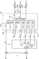
図1は、本発明に係る変圧器の第1の実施の形態の主要部の構成を示す斜視図である。図2は、第1の実施の形態に係る変圧器の回路構成を示す図である。 FIG. 1 is a perspective view showing a configuration of a main part of a transformer according to a first embodiment of the present invention. FIG. 2 is a diagram illustrating a circuit configuration of the transformer according to the first embodiment.
図1に示す変圧器A1は、第1のコイル1(図1では見えていない。図12参照)の外側に第2のコイル2を同心状に配置した長方形のリング形状を有するコイル部Bと、コイル部Bの2つの長辺の部分(脚部)の一方に装着された円筒状の鉄心Cとを備える。第1のコイル1と第2のコイル2は、後述するようにそれぞれコイルボビン101(図3,図4参照)とコイルボビン201(図6,図7参照)を用いて製作されている。
A transformer A1 shown in FIG. 1 includes a coil part B having a rectangular ring shape in which a
変圧器A1は、第1のコイル1に電力系統から6000[V]以上の高圧が印加され、第2のコイル2から需要家に供給する規定の低圧(例えば、100[V]若しくは200[V]が出力される、配電用変圧器に適用した一例である。
In the transformer A1, a high voltage of 6000 [V] or more is applied to the
変圧器A1では、第1のコイル1に高圧が入力され、第2のコイル2から低圧が出力されるので、変圧器A1の第1のコイル1が一次コイルとなり、第2のコイル2が二次コイルとなっている。また、変圧器A1の第1のコイル1が高圧コイルとなり、第2のコイル2が低圧コイルとなっている。
In the transformer A1, a high voltage is input to the
変圧器A1は、図2に示す変圧器A1の回路構成の点線で示す部分に相当している。以下の説明では、第1のコイル1を「一次コイル1」若しくは「高圧コイル1」と称し、第2のコイル2を「二次コイル2」若しくは「低圧コイル2」と称して説明する。
The transformer A1 corresponds to a portion indicated by a dotted line in the circuit configuration of the transformer A1 shown in FIG. In the following description, the
変圧器A1の一次コイル1は、図2に示すように、一次巻線102の巻数n1の主要部を構成する主要巻線1021と、一次巻線102の巻数n1の巻線調整部(巻数n1の巻数を調整する部分)を構成する巻数調整用巻線1022を有する。
The
変圧器A1は、降圧用変圧器であるので、二次コイル(低圧コイル)2の二次巻線202の巻数n2は、一次コイル(高圧コイル)1の一次巻線102の巻数n1よりも少ない。一次コイル(高圧コイル)1に流れる一次電流は、二次コイル(低圧コイル)2に流れる二次電流よりも小さいので、一次巻線102の線径は、二次巻線202の線径よりも小さい。 Transformer A1 are the step-down transformer, the number of turns n 2 of the secondary coil (low voltage coil) secondary winding 202, from the number of turns n 1 of the primary coil (high voltage coil) 1 of the primary winding 102 There are few. Since the primary current flowing through the primary coil (high voltage coil) 1 is smaller than the secondary current flowing through the secondary coil (low voltage coil) 2, the wire diameter of the primary winding 102 is larger than the wire diameter of the secondary winding 202. small.
巻数調整用巻線1022は、3個の小巻線1022a,1022b,1022cを有する。主要巻線1021は、2つに分割された分割巻線1021a,分割巻線1021bを有する。後述するように、コイルボビン101の一次巻線102を整列巻きするための凹溝1012(図4参照)の空間は、幅方向に二分割されている。巻数調整用巻線1022の3個の小巻線1022a,1022b,1022cは、凹溝1012の一方の空間(以下、「第1の空間」という。)に整列巻きされるが、主要巻線1021は巻数調整用巻線1022に接続される側の一部が凹溝1012の第1の空間に整列巻きされ、残りが凹溝1012の他方の空間(以下、「第2の空間」という。)に整列巻きされる。
The winding number adjusting winding 1022 has three
第1の実施の形態では、主要巻線1021の凹溝1012の第1の空間に整列巻きされる部分と第2の空間に整列巻きされる部分は、コイルボビン101の外部で直列に接続される構成であるので、主要巻線1021を二分割し、一方の分割巻線1021aを凹溝1012の第1の空間に整列巻きし、他方の分割巻線1021bを凹溝1012の第2の空間に整列巻きするようにしている。
In the first embodiment, the portion of the
変圧器A1の回路構成では、3個の小巻線1022a,1022b,1022cは直列に接続され、巻数調整用巻線1022の小巻線1022cと主要巻線1021が直列に接続される。そして、小巻線1022aと小巻線1022b、小巻線1022bと小巻線1022c、小巻線1022cと主要巻線1021の各接続点と小巻線1022aの開放された端子がタップとなる。
In the circuit configuration of the transformer A1, the three
図2に示す変圧器A1の回路構成は、図1に示す変圧器A1をタンク(図示省略)に収納し、当該タンクに配設されるブッシングや当該タンクに内蔵されるタップ切換器TLに所要の電気的な接続を行って完成される。 The circuit configuration of the transformer A1 shown in FIG. 2 is required for the bushing disposed in the tank and the tap changer TL built in the tank. The electrical connection is completed.
タンクには、一次電圧v1を印加するための一対の一次ブッシングBS1(+),BS1(−)と、二次電圧v2を出力するための3個の二次ブッシングBS2(+),BS2(−)2,BS2(G)((G)は、接地されたブッシングであることを示す。)と、一次ブッシング中継端子Q1が配設されている。一次ブッシングS1(−)は、一次ブッシング中継端子Q1に接続されている。 The tank, a pair of primary bushing BS1 for applying a primary voltage v 1 (+), BS1 ( -) and three secondary bushing BS2 for outputting a secondary voltage v 2 (+), BS2 (-) 2, BS2 (G ) (. (G) is indicative of a bushing which is grounded) and the primary bushing relay terminal Q 1 is disposed. Primary bushing S1 (-) is connected to the primary bushing relay terminal Q 1.
タップ切換器TLには4つのタップ端子P1〜P4と、切換片TCによっていずれかのタップ端子に接続されるコモン端子Pcとが設けられている。タップ切換器TLのコモン端子Pcは、一次ブッシングBS1(+)に接続されている。小巻線1022aの両端はそれぞれタップ端子P1とタップ端子P2に接続され、小巻線1022bの両端はそれぞれタップ端子P2とタップ端子P3に接続され、小巻線1022cの両端はそれぞれタップ端子P3とタップ端子P4に接続される。分割巻線1021aの一方端と分割巻線1021bの他方端はそれぞれタップ端子P4と一次ブッシング接続端子Q1に接続され、分割巻線1021aの他方端と分割巻線1021bの一方端はコイルボビン101の外部で互いに接続される。
The tap changer TL is provided with four tap terminals P 1 to P 4 and a common terminal P c connected to any one of the tap terminals by the switching piece TC. The common terminal Pc of the tap changer TL is connected to the primary bushing BS1 (+). Ends of
図2では、主要巻線1021と巻数調整用巻線1022の接続点を示すために、接続点T1〜T5を記載している。従って、図2では、小巻線1022aの両端をそれぞれ接続点T1と接続点T2に接続し、小巻線1022bの両端をそれぞれ接続点T2と接続点T3に接続し、小巻線1022cの両端をそれぞれ接続点T3と接続点T4に接続している。また、分割巻線1021aの両端をそれぞれ接続点T4と接続点T5に接続し、分割巻線1021bの一方端を接続点T5に接続している。
In FIG. 2, connection points T 1 to T 5 are illustrated in order to indicate connection points between the main winding 1021 and the winding number adjustment winding 1022. Thus, in FIG. 2, to connect the two ends of the
図1に示すように、変圧器A1のコイル部Bからは分割巻線1021aの両端部、分割巻線1021bの両端部、小巻線1022a,1022b,1022cの各両端部が引き出されている。また、図12に示すように、変圧器A1のコイル部Bからは二次巻線202の両端部と中間位置cも引き出されている。図1では、コイル部Bから引き出された二次巻線202の両端部と中間位置cの部分は見えていない。
As shown in FIG. 1, both ends of the divided winding 1021a, both ends of the divided winding 1021b, and both ends of the
図1に示す引出線La1,La2は、小巻線1022aの両端から引き出された線であり、引出線Lb1,Lb2は、小巻線1022bの両端から引き出された線であり、引出線Lc1,Lc2は、小巻線1022cの両端から引き出された線である。引出線Ld1,Ld2は、主要巻線1021の分割巻線1021aの両端から引き出された線であり、引出線Le1,Le2は、主要巻線1021の分割巻線1021bの両端から引き出された線である。また、図12に示す引出線Lf1,Lf2は、二次巻線202の両端から引き出された線であり、引出線Lf3は、二次巻線202の中間位置cから引き出された線である。 The lead lines L a1 and L a2 shown in FIG. 1 are lines drawn from both ends of the small winding 1022a, and the lead lines L b1 and L b2 are lines drawn from both ends of the small winding 1022b, The lead lines L c1 and L c2 are lines drawn from both ends of the small winding 1022c. The lead lines L d1 and L d2 are drawn from both ends of the split winding 1021a of the main winding 1021, and the lead lines L e1 and L e2 are drawn from both ends of the split winding 1021b of the main winding 1021. It is a line. Further, the lead lines L f1 and L f2 shown in FIG. 12 are lines drawn from both ends of the secondary winding 202, and the lead line L f3 is a line drawn from the intermediate position c of the secondary winding 202. It is.
変圧器A1がタンクに収納される際、巻数調整用巻線1022の3個の小巻線1022a,1022b,1022cから引き出された引出線La1,La2,Lb1,Lb2,Lc1,Lc2は、引出線La1,La2がタップ切換器TLのタップ端子P1とタップ端子P2に、引出線Lb1,Lb2がタップ切換器TLのタップ端子P2とタップ端子P3に、引出線Lc1,Lc2がタップ切換器TLのタップ端子P3とタップ端子P4にそれぞれ接続される。
When the transformer A1 is housed in the tank, the lead lines L a1 , L a2 , L b1 , L b2 , L c1 , led out from the three
また、主要巻線1021の分割巻線1021aから引き出された一方の引出線Ld1は、タップ切換器TLの接続点T4に接続され、主要巻線1021の分割巻線1021bから引き出された他方の引出線Le2は、一次ブッシングBS1(−)に接続され、分割巻線1021aから引き出された他方の引出線Ld2と分割巻線1021bから引き出された一方の引出線Le1は互いに接続される。二次コイル2から引き出された引出線Lf1,Lf2,Lf3は、二次ブッシングBS2(+)と二次ブッシングBS2(−)と二次ブッシングBS(G)にそれぞれ接続される。
Further, one lead wire L d1 drawn from a discrete winding
変圧器A1では、タップ切換器TLでコモン端子Pcと接続するタップ端子P1〜P4を切り換えることにより、一次巻線102の巻数n1を4段階に切り換えることができる。3個の小巻線1021a,1021b,1021cの巻数をそれぞれna,nb,ncとし、主要巻線1021の巻数をndとすると、一次巻線102の巻数n1は、(na+nb+nc+nd)、(nb+nc+nd)、(nc+nd)、ndの4種類に切り換えることができる。
The transformer A1, by switching the
以下の説明では、第1の実施の形態に係る変圧器A1を配電用6600[V]/(210−105[V]変圧器に適用する場合について、説明する。 In the following description, a case where the transformer A1 according to the first embodiment is applied to a 6600 [V] / (210-105 [V] transformer for power distribution will be described.
6600[V]/(210−105)[V]変圧器が配置される需要家の周辺は、配電変電所からの距離によって、変圧器の一次コイルに入力される一次電圧が大きく変動するので、一般に、配電変電所からは6600[V]よりも高い電圧で送電される。このため、変圧器Aの一次コイル1に入力される一次電圧v1は、配電変電所に近い場所では6600[V]以上の高圧になり、配電変電所から遠い場所では6600[V]以下の高圧になることがある。
6600 [V] / (210-105) [V] Because the primary voltage input to the primary coil of the transformer greatly fluctuates depending on the distance from the distribution substation around the customer where the transformer is arranged, In general, power is transmitted from a distribution substation at a voltage higher than 6600 [V]. Therefore, the primary voltage v 1 input to the
第1の実施の形態に係る変圧器A1は、一次電圧v1の大きさによって一次コイル1の巻数を4段階に調整し、二次コイル2から安定した(210−105)[V]の二次電圧v2を出力できるようにしている。具体的には、一次電圧v1をvA、vB、vC、vD(vA>vB>vC>vD)の4種類に分け、各電圧値に4つのタップを対応させている。
Transformers A1 according to the first embodiment, by adjusting the number of turns of the
変圧器A1の変圧比は、(v1/v2)=(n1/n2)で表される。v2、n2は固定であるので、一次巻線102の巻数n1は、一次電圧v1に比例する。従って、各タップの電圧vA、vB、vC、vDに、一次巻線102の巻数(na+nb+nc+nd)、(nb+nc+nd)、(nc+nd)、ndがそれぞれ対応する。 The transformation ratio of the transformer A1 is represented by (v 1 / v 2 ) = (n 1 / n 2 ). Since v 2 and n 2 are fixed, the number of turns n 1 of the primary winding 102 is proportional to the primary voltage v 1 . Therefore, the number of turns (n a + n b + n c + n d ), (n b + n c + n d ), (n c + n d ), and (n c + n d ) are applied to the voltages v A , v B , v C , v D of each tap. ) And n d correspond to each other.
タップ電圧vA、vB、vC、vDは、通常、規格や客先の仕様書等で決められている。例えば、vA=6750[V]、vB=6600[V]、vC=6450[V]、vD=6300[V]に規定されている場合、vA−vB=vB−vC=vC−vD=150[V]であるから、na=nb=ncとなる。すなわち、3個の小巻線1022a,1022b,1022cの巻数は、同一となる。
The tap voltages v A , v B , v C , and v D are usually determined by standards, customer specifications, and the like. For example, when v A = 6750 [V], v B = 6600 [V], v C = 6450 [V], and v D = 6300 [V], v A −v B = v B −v C = v C -v D = 150 because it is [V], a n a = n b = n c . That is, the number of turns of the three
次に、一次コイル1と二次コイル2の構造について、説明する。まず、一次コイル1の構造について、図3〜図5を用いて説明する。
Next, the structure of the
以下の説明では、第1の実施の形態に係る変圧器Aの4つのタップ電圧を6750[V]、6600[V]、6450[V]、6300[V]に設定した場合を例に説明する。この場合の例では、3個の小巻線1022a,1022b,1022cの巻数をnsとすると、vC/vD=(nd+ns)/nd=6450/6300より、主要巻線1021の巻数ndと小巻線1022a,1022b,1022cの巻数nsの間にはnd=42×nsの関係がある。
In the following description, the case where the four tap voltages of the transformer A according to the first embodiment are set to 6750 [V], 6600 [V], 6450 [V], and 6300 [V] will be described as an example. . In the example in this case, three
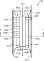
図3は、変圧器の一次コイル1を製作するためのコイルボビン(本発明に係るコイルボビン)を正面から見た図、図4は、同コイルボビンを右側面から見た図、図5は、同コイルボビンの図4におけるX−X線断面図である。
3 is a front view of a coil bobbin (coil bobbin according to the present invention) for manufacturing the
以下の説明では、一次コイル1を製作するためのコイルボビンと二次コイルを製作するためのコイルボビンを区別するため、一次コイル1用のコイルボビンを「第1のコイルボビン」と称し、二次コイル2用のコイルボビンを「第2のコイルボビン」と称する。
In the following description, in order to distinguish the coil bobbin for manufacturing the
また、図3において、リング形状の外周に沿う面を「外周側面」と称し、内周に沿う面を「内周側面」と称し、図4において、ボビン本体1011の左側の面を「正面」と称し、右側の面を「背面」と称して説明をする。
3, the surface along the outer periphery of the ring shape is referred to as “outer peripheral side surface”, the surface along the inner periphery is referred to as “inner peripheral side surface”, and the left surface of the bobbin
一次コイル1は、第1のコイルボビン101を用いて長方形のリング状に成形される。第1のコイルボビン101は、図3,図4に示すように、背の低い長方形のリング形状を有するボビン本体1011を備える。ボビン本体1011は、樹脂を成形して作製されている。
The
ボビン本体1011は、外周側面に一次巻線102を巻回するための凹溝1012が形成されており、外周側面以外の部分(ボビン本体1011の内周側面の部分)の外形形状が半円形状に成形されている(図5,図12参照)。
The bobbin
ボビン本体1011の内周側面の外形形状を半円形状にしているのは、ボビン本体1011の2つの長辺の部分の一方に、図1に示すように、円筒状の鉄心Cが装着されるため、当該鉄心Cの穴の内側面をボビン本体1011に密着させるためである。従って、ボビン本体1011の外形形状を半円形状にした部分の半径は、鉄心Cの穴の半径より僅かに小さいサイズに設定されている。
The reason why the outer shape of the inner peripheral side surface of the bobbin
ボビン本体1011の外周側面に形成された凹溝1012は、主要巻線1021が巻回される第1の凹溝1013と巻数調整用巻線1022が巻回される第2の凹溝1014を有する。第2の凹溝1014は、第1の凹溝1013の底面1013Bの幅方向(図4において横方向)の中央に穿設されている。
The
第2の凹溝1014の底面の中央には、凹溝1012の空間を幅方向に分割する分割壁1018が設けられている。図4において、分割壁1018で分割された凹溝1012の左側の空間が「第1の空間」に相当し、右側の空間が「第2の空間」に相当する。
A dividing
分割壁1018は、第2の凹溝1014の両内壁面1014Aと平行になるように底面1014Bに対して垂直に設けられている。分割壁1018は、底面1014Bから第1の凹溝1013の正面側の内壁面1013Aの上端付近までの高さを有する薄板状の部材である。分割壁1018は、樹脂の一体成形によりボビン本体1011の底面1014Bに設けられている。
The dividing
第2の凹溝1014の図4におけるX−X線断面の形状(以下、この形状を「横断面形状」という。)は、第2の凹溝1014の底面1014Bに対して両内壁面1014Aが垂直に立ち上がる形状(長方形の形状)となっている(図5参照)。これは、3個の小巻線1022a,1022b,1022cを第2の凹溝1014の第1の空間にそれぞれ二層に整列巻きしたときの各巻数を同一にするためである。
The cross-sectional shape of the
一方、第1の凹溝1013は、第1の凹溝1013の底面1013Bに対して両内壁面1013Aがそれぞれ外側に所定の傾斜角θで傾斜するように立ち上がる形状(等脚台形の形状)となっている(図6参照)。第1の凹溝1013及び第2の凹溝1014の横断面形状とサイズの詳細については、後述する。
On the other hand, the first
ボビン本体1011の正面側の長方形の外形寸法(L1(長手方向の長さ)×W1(短手方向の長さ))は、ボビン本体1011の背面側の長方形の外形寸法(L2(長手方向の長さ)×W2(短手方向の長さ))よりも小さいサイズに設定されている。これは、図12に示すように、第1のコイルボビン101を第2のコイルボビン201の穴の部分に嵌入してコイル部Bを一次コイル1の外側に二次コイル2が同心状に配置された構造にするためである。
The rectangular external dimension (L1 (length in the longitudinal direction) × W1 (length in the short direction)) of the front side of the
従って、ボビン本体1011の正面側の長方形の外形寸法(L1×W1)は、第2のコイルボビン201の穴の部分の長方形の寸法(L3(長手方向の長さ)×W3(短手方向の長さ))(図6参照)より僅かに小さいサイズに設定されている。一方、ボビン本体1011の背面側の長方形の外形寸法(L2×W2)は、長方形のリング形状を有する第2のコイルボビン201の外形寸法(L4(長手方向の長さ)×W4(短手方向の長さ))(図6参照)と略同一の寸法に設定されている。
Therefore, the rectangular outer dimension (L1 × W1) on the front side of the bobbin
ボビン本体1011の正面側の側面のうち、一方の長辺の部分(図3では、右側の長辺の部分)に、5個の切り欠き部1015A,1015B,1015C,1015D,1015Eが設けられている。
切り欠き部1015Aは、第2の凹溝1014の第1の空間に整列巻きされる小巻線1022aの一方の引出線La1をボビン本体1011の外部に引き出し、切り欠き部1015Bは、小巻線1022aの他方の引出線La2と小巻線1022bの一方の引出線Lb1をボビン本体1011の外部に引き出し、切り欠き部1015Cは、小巻線1022bの他方の引出線Lb2と小巻線1022cの一方の引出線Lc1をボビン本体1011の外部に引き出すためのものである。
また、切り欠き部1015Dは、小巻線1022cの他方の引出線Lc2と第1の凹溝1013の第1の空間に整列巻きされる主要巻線1021の分割巻線1021aの一方の引出線Ld1をボビン本体1011の外部に引き出し、切り欠き部1015Eは、分割巻線1021aの他方の引出線Le2をボビン本体1011の外部に引き出すためのものである。
Of the side surface on the front side of the bobbin
Further,
一方、ボビン本体1011の背面側の側面の切り欠き部1015Eと向かい合う位置に、切り欠き部1015Fが設けられ、切り欠き部1015Aと向かい合う位置に、切り欠き部1015Gが設けられている(図4参照)。切り欠き部1015Fは、凹溝1012の第2の空間に整列巻きされる主要巻線1021の分割巻線1021bの一方の引出線Le1をボビン本体1011の外部に引き出すためのものであり、切り欠き部1015Gは、主要巻線1021の分割巻線1021bの他方の引出線Le2をボビン本体1011の外部に引き出すためのものである。以下の説明では、切り欠き部を「巻線引出部」と称する。
On the other hand, a
3個の巻線引出部1015A,1015B,1015Cは、ボビン本体1011の外周側面から第2の凹溝1014の底面1014Bまでの深さを有し、ボビン本体1011の正面側から第2の凹溝1014まで貫通するように形成されている(図5参照)。巻線引出部1015Fも、ボビン本体1011の外周側面から第2の凹溝1014の底面1014Bまでの深さを有し、ボビン本体1011の背面側から第2の凹溝1014まで貫通するように形成されている。
The three winding
巻線引出部1015Dは、ボビン本体1011の外周側面から第1の凹溝1013の底面1013Bまでの深さを有し、ボビン本体1011の正面側から第1の凹溝1013まで貫通するように形成されている(図5参照)。巻線引出部1015Eは、ボビン本体1011の外周側面から第1の凹溝1013の所定の深さ位置までの深さを有し、ボビン本体1011の正面側から第1の凹溝1013まで貫通するように形成されている(図5参照)。
巻線引出部1015Gは、ボビン本体1011の外周側面から第1の凹溝1013の傾斜した内側壁1013Aの上端位置までの深さを有し、ボビン本体1011の背面側から第1の凹溝1013まで貫通するように形成されている。
The winding
The winding lead portion 1015G has a depth from the outer peripheral side surface of the bobbin
巻線引出部1015A〜1015Fによる一次コイル1の冷却効果を上げるために、図4の仮想線(二点差線)で示すように、巻線引出部1015Dと巻線引出部1015Eを、ボビン本体1011の外周側面から第2の凹溝1014の底面1014Bまでの深さを有し、ボビン本体1011の正面側から第2の凹溝1014まで貫通するように形成してもよい。また、巻線引出部1015Gを、ボビン本体1011の外周側面から第2の凹溝1014の底面1014Bまでの深さを有し、ボビン本体1011の背面側から第2の凹溝1014まで貫通するように形成してもよい。
In order to increase the cooling effect of the
次に、第1の凹溝1013及び第2の凹溝1014の横断面形状とサイズについて、説明する。まず、第2の凹溝1014の横断面形状とサイズについて、説明する。
Next, the cross-sectional shape and size of the
第2の凹溝1014は、3個の小巻線1022a,1022b,1022cをそれぞれ巻数nsだけ整列巻きするために、長方形の断面形状を有している。第2の凹溝1014の底面1014Bには、図9に示すように、当該底面1014Bに巻き付けられる小巻線1022aと分割巻線1021bが整列するように巻き付け位置をガイドするための第1のガイド溝1016が設けられている。
The
第1の実施の形態では、図10に示すように、一次巻線102の一方の端部に配置される小巻線1022aが、一方の引出線La1を巻線引出部1015Aからボビン本体1011の外部に引き出した状態で第2の凹溝1014の内壁面1014Aから第1のガイド溝1016に沿って分割壁1018まで巻き付けられる。その後、小巻線1022aは折り返され、巻回された小巻線1022aの上側に元の内壁面1014A(巻線引出部1015Aを有する内壁面1014A)まで巻き付けられた後、他方の引出線La2が巻線引出部1015Aからボビン本体1011の外部に引き出される。
First In the embodiment, as shown in FIG. 10,
小巻線1022aの1層目は、第1のガイド溝1016に沿って第2の凹溝1014の底面1014Bに巻き付けられるが、小巻線1022aの2層目以降は、下層の整列巻線の上面に形成される巻線同士の窪みをガイドとして巻き付けられる。小巻線1022aの層数を2×k(kは正の整数)とすると、各層のターン数はns/(2×k)[ターン]となるので、巻数調整用巻線1022に用いられる巻線の線径をφ1[mm]とすると、各層に整列巻きされた巻線の幅方向の寸法は、φ1×ns/(2×k)となっている。
The first layer of the small winding 1022a is wound around the bottom surface 1014B of the second
小巻線1022aの下層に整列巻きされる巻線は、上層に整列巻きされる巻線に対して底面1014Bの幅方向にφ1/2[mm]だけ位置がずれるので、第1の空間における第2の凹溝1014の幅方向の寸法w1[mm](図10参照)は、w1=φ1×ns/(2×k)+φ1/2=(φ1/2)×[(ns/k)+1]に設定されている。
Winding which is wound regularly under the
第1のガイド溝1016は、φ1/2[mm]よりも短い溝幅を有する断面形状が円弧形状の溝である(図9参照)。第1のガイド溝1016は、第2の凹溝1014の底面1014Bの幅方向にφ1[mm]のピッチでns/(2×k)[本]形成されている。
The
巻数調整用巻線1022の小巻線1022bは、図10に示すように、小巻線1022aの外側(図10では上側)に2層構造で巻回される。小巻線1022bは、一方の引出線Lb1を巻線引出部1015Bからボビン本体1011の外部に引き出した状態で第2の凹溝1014の内壁面1014Aから小巻線1022aの2層目の上面に形成される巻線同士の窪みをガイドとして分割壁1018まで巻き付けられる。その後、小巻線1022bは、折り返され、巻回された小巻線1022aの上側に元の内壁面1014A(第2の凹溝1014を有する内壁面1014A)まで巻き付けられた後、他方の引出線Lb2が巻線引出部1015Bからボビン本体1011の外部に引き出される。
As shown in FIG. 10, the small winding 1022b of the winding number adjusting winding 1022 is wound in a two-layer structure on the outer side (upper side in FIG. 10) of the small winding 1022a.
巻数調整用巻線1022の小巻線1022cは、図10に示すように、小巻線1022bの外側(図10では上側)に2層構造で巻回される。小巻線1022bは、一方の引出線Lc1を巻線引出部1015Cからボビン本体1011の外部に引き出した状態で第2の凹溝1014の内壁面1014Aから小巻線1022bの2層目の上面に形成される巻線同士の窪みをガイドとして分割壁1018まで巻き付けられる。その後、小巻線1022cは、折り返され、巻回された小巻線1022bの上側に元の内壁面1014A(第2の凹溝1014を有する内壁面1014A)まで巻き付けられた後、他方の引出線Lc2が巻線引出部1015Cからボビン本体1011の外部に引き出される。
As shown in FIG. 10, the small winding 1022c of the winding adjustment winding 1022 is wound in a two-layer structure on the outside (upper side in FIG. 10) of the small winding 1022b.
小巻線1022b,1022cも小巻線1022aと同様に、各層のターン数はns/(2×k)[ターン]であり、各層に整列巻きされた巻線の幅方向の寸法は、(φ1×ns/(2×k)となっている。
Similarly to the small winding 1022a, the
第2の凹溝1014には、3個の(2×k)層に整列巻きされた小巻線1022a,1022b,1022cを3段(6×k)層に積層するように、巻数調整用巻線1022が巻回されるので、第2の凹溝1014の深さの寸法h1[mm](図10参照)は、各層の巻線の重なり部分の寸法をΔh1[mm]とすると、凡そ(積層数−1)×(φ1−Δh1)+φ1=(6×k−1)×(φ1−Δh1)+φ1[mm]に設定されている。
In the second
次に、第1の凹溝1013の横断面形状とサイズについて、説明する。
Next, the cross-sectional shape and size of the first
第1の凹溝1013は、上底の長さが下底の長さよりも長く、下底の両端の内角が120°である等脚台形の横断面形状を有している。すなわち、第1の凹溝1013の開口が外周側面に向かって末広がりに広くなるように、第1の凹溝1013の両内壁面1013Aが底面1013Bに対して傾斜角θ=120°で傾斜している。
The
第1の凹溝1013の空間は、第2の凹溝1014の幅方向の中央に突設された分割壁1018によって幅方向に二分割されているので、分割巻線1021aが整列巻きされる第1の凹溝1013の第1の空間は、下底の左側の内角が120°で、右側の内角が直角である台形の横断面形状を有し、分割巻線1021bが整列巻きされる第1の凹溝1013の第2の空間は、下底の左側の内角が直角で、右側の内角が120°である台形の横断面形状を有している。
The space of the
第1の凹溝1013の両内壁面1013Aを底面1013Bに対して傾斜角θ=120°で傾斜させているのは、図11に示すように、両内壁面1013Aの部分で各層の巻線と内壁面1013Aの間に隙間が生じないようにして、第1の凹溝1013における一次巻線102の占積率を高くするためである。
As shown in FIG. 11, both inner wall surfaces 1013A of the
層状に整列巻きされる主要巻線1021の分割巻線1021a,1021bは、上層の巻線が下層の整列巻きされた巻線の窪みをガイドとして整列巻きされるので、両内壁面1013Aの部分で各層の巻線と内壁面1013Aの間に隙間が生じないようにするには、内壁面1013Aを各層の端に位置する巻線の接線に一致させればよい。
The
下層の整列巻きの端に位置する巻線と上層の整列巻きの端に位置する巻線は、図11に示すように、幅方向でφ1/2だけ相互に位置がずれるから、各層の端に位置する巻線の接線の底面1013Bに対する角度は120°になる。従って、第1の凹溝1013の両内壁面1013Aの底面1013Bに対する傾斜角θは120°に設定されている。
As shown in FIG. 11, the winding located at the end of the lower aligned winding and the winding positioned at the upper aligned winding are shifted from each other by φ 1/2 in the width direction. The angle of the tangent to the
第1の凹溝1013の底面1013Bにも第2の凹溝1014の底面1014Bと同様に、第1の凹溝1013に巻き付けられる主要巻線1021が整列するように巻き付け位置をガイドするための第2のガイド溝1017が設けられている。
Similarly to the bottom surface 1014B of the second
第2のガイド溝1017は、第1のガイド溝1016と同一サイズの円弧状の断面形状を有する溝である。第2のガイド溝1017は、第1のガイド溝1016と同様に、第1の凹溝1013の底面1013Bに、幅方向にφ1[mm]のピッチで形成されている(図11参照)。
The
主要巻線1021の分割巻線1021aは、一方の引出線Ld1を巻線引出部1015Dからボビン本体1011の外部に引き出した状態で第1の凹溝1013の内壁面1013Aから第2のガイド溝1017に沿って巻回される。分割巻線1021aは、分割壁1018まで巻回されると折り返され、整列巻きされた1層目の分割巻線1021aの上側に形成される巻線同士の窪みをガイドとして元の内壁面1013A(巻線引出部1015Dを有する内壁面1014A)まで巻き付けられる。その後、主要巻線1021は、整列巻きされた各層の主要巻線1021の上側に形成される巻線同士の窪みをガイドとして分割壁1018と内壁面1013Aに到達する毎に折り返されながら、積層数が所定数となるまで巻回され、他方の引出線Ld2が巻線引出部1015Eからボビン本体1011の外部に引き出される。
Discrete winding 1021a of the primary winding 1021, a second guide groove from the
一方、主要巻線1021の分割巻線1021bは、一方の引出線Le1を巻線引出部1015Fからボビン本体1011の外部に引き出した状態で第1の凹溝1013の内壁面1013Aから第2のガイド溝1017に沿って巻回される。分割巻線1021bは、分割壁1018まで巻回されると折り返され、整列巻きされた1層目の分割巻線1021bの上側に形成される巻線同士の窪みをガイドとして元の内壁面1013A(巻線引出部1015Eを有する内壁面1014A)まで巻き付けられる。その後、主要巻線1021は、整列巻きされた各層の主要巻線1021の上側に形成される巻線同士の窪みをガイドとして分割壁1018と内壁面1013Aに到達する毎に折り返されながら、積層数が所定数となるまで巻回され、他方の引出線Le2が巻線引出部1015Gからボビン本体1011の外部に引き出される。
On the other hand, the split winding 1021b of the main winding 1021 has a second lead wire L e1 extending from the
主要巻線1021は、上述したように分割巻線1021aが第1の凹溝1013の第1の空間に層状に整列巻きされ、分割巻線1021bが第2の凹溝1014及び第1の凹溝1013の第2の空間に層状に整列巻きされる。主要巻線1021の線材は、巻数調整用巻線1022の線材と同一であるので、分割巻線1021bの第2の凹溝1014の第2の空間におけるターン数N1は、巻数調整用巻線1022の第2の凹溝1014の第2の空間におけるターン数(3×ns)と同一になる。
As described above, the main winding 1021 has the divided
従って、第1の凹溝1013には、主要巻線1021の巻数ndのうち、凡そ(nd−3×ns)[ターン]が巻回される。第1の凹溝1013における主要巻線1021の積層数をmとすると、第1の凹溝1013の深さの寸法h2[mm](図10参照)は、各層の重なり部分の寸法をΔh[mm]とすると、凡そ(m−1)×(φ1−Δh)+φ1[mm]に設定されている。
Accordingly, approximately (n d −3 × n s ) [turns] of the number of turns n d of the main winding 1021 are wound in the first
第1の実施の形態に係る第1のコイルボビン101では、正面から見て左側の脚部に鉄心Cが巻き付けられるので、正面から見て右側の脚部に相当する部分に巻線引出部1015A〜1015Gを形成しているが、正面から見て左側の脚部に相当する部分に巻線引出部1015A〜1015Gを形成し、正面から見て右側の脚部に鉄心Cを巻き付ける構成にしてもよい。
In the
また、第1の実施の形態に係る第1のコイルボビン101では、正面側の側面(左側の側面)に巻線引出部1015A〜1015Eを形成し、背面側の側面(右側の側面)に巻線引出部1015F,1015Gを形成しているが、背面側の側面(右側の側面)に巻線引出部1015A〜1015Eを形成し、正面側の側面(左側の側面)に巻線引出部1015F,1015Gを形成するようにしてもよい。
In the
すなわち、図4において、巻線引出部1015A〜1015Eと巻線引出部1015F,1015Gが左右対称となるように、巻線引出部1015A〜1015Eを右側の側面に形成し、巻線引出部1015F,1015Gを左側の側面に形成するようにしてもよい。
That is, in FIG. 4, the winding
次に、二次コイル2の構造について、図6〜図8を用いて説明する。
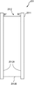
Next, the structure of the
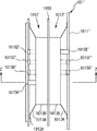
図6は、変圧器A1の二次コイル2を製作するための第2のコイルボビン201を正面から見た図、図7は、第2のコイルボビン201を右側面から見た図、図8は、第2のコイルボビン201の図6におけるY−Y線断面図である。
6 is a view of the
第2のコイルボビン201は、図6,図7に示すように、背の低い長方形のリング形状を有するボビン本体2011を備える。ボビン本体2011は、ボビン本体1011と略同じ寸法の高さ寸法(図7の幅方向の寸法)を有する。
As shown in FIGS. 6 and 7, the
ボビン本体2011の側面から見た形状は、略左右対称になっているが、以下では、説明の便宜上、図6において、リング形状の外周に沿う面を「外周側面」と称し、内周に沿う面を「内周側面」と称し、図7において、ボビン本体2011の左側の面を「正面」と称し、右側の面を「背面」と称して説明をする。
The shape viewed from the side surface of the bobbin
ボビン本体2011は、外周側面に二次巻線202(図8参照)を巻回するための凹溝2012が形成されており、穴の部分の形状は直方体形状に成形されている(図8,図12参照)。ボビン本体2011の穴の部分の形状を直方体形状としているのは、図12に示すように、この穴の部分にボビン本体1011が嵌入装着されるからである。
The bobbin
ボビン本体2011の穴の部分の長方形の寸法(L3(長手方向の長さ)×W3(短手方向の長さ))は、上述したようにボビン本体1011の正面側の長方形の外形寸法(L1×W1)より僅かに大きいサイズに設定されている。また、ボビン本体2011の外周側面側の長方形の外形寸法(L4(長手方向の長さ)×W4(短手方向の長さ))は、上述したようにボビン本体1011の背面側の長方形の外形寸法(L2×W2)と略同一の寸法に設定されている。
The rectangular dimension (L3 (length in the longitudinal direction) × W3 (length in the short direction)) of the hole portion of the
ボビン本体2011の正面側のリング状の側面のうち、一方の長辺の中央部分(図6では、左側の長辺の部分)に、1個の切り欠き部2013が設けられている。切り欠き部1013は、凹溝2012に巻回される二次巻線202の両端部と中間位置cをボビン本体2011の外部に引き出すためのものである。以下の説明では、ボビン本体2011の切り欠き部も「巻線引出部」と称する。
Of the ring-shaped side surface on the front side of the bobbin
巻線引出部2013は、ボビン本体2011の外周側面から凹溝2012の底面2012Bまでの深さを有し、ボビン本体2011の正面側から凹溝2012まで貫通するように形成されている。ボビン本体2011の巻線引出部2013から引き出された二次巻線202の両端部が図12の引出線Lf1,Lf2に相当し、二次巻線202の中間位置cの部分が図12の引出線Lf3に相当する。
The winding
凹溝2012は、凹溝2012の底面2012Bに対して両内壁面2012Aが垂直に立ち上がる形状(長方形の断面形状)となっている(図8参照)。凹溝2012の底面2012Bには、第2の凹溝1014の底面1014Bと同様に、当該底面2014Bに巻き付けられる二次巻線202が整列するように巻き付け位置をガイドするためのガイド溝2014が設けられている。
The
二次巻線202は、一方の引出線Lf1を巻線引出部2013からボビン本体1011の外部に引き出した状態で凹溝2012の内壁面2012Aからガイド溝2014に沿って巻回される。二次巻線202は、反対側の内壁面2012Aまで巻回されると折り返され、整列巻きされた1層目の二次巻線202の上側に形成される巻線同士の窪みをガイドとして元の内壁面2012A(巻線引出部2013を有する内壁面2012A)まで巻き付けられる。その後、二次巻線202は、整列巻きされた各層の二次巻線202の上側に形成される巻線同士の窪みをガイドとして内壁面2012Aに到達する毎に折り返されながら、積層数が所定数となるまで巻回され、他方の引出線Lf2が巻線引出部2013からボビン本体2011の外部に引き出される。
The secondary winding 202 is wound along the guide groove 2014 from the
二次巻線202の1層目は、ガイド溝2014に沿って凹溝2012の底面2012Bに巻き付けられるが、二次巻線202の2層目は、1層目の上面に形成される巻線同士の窪みをガイドとして巻き付けられる。二次巻線202の各層のターン数をnt[ターン]とし、二次巻線202に用いられる巻線の線径をφ2(>φ1)[mm]とすると、凹溝2012の底面2012Bの幅方向の寸法は、φ2(=nt+1/2)に設定されている。
The first layer of the secondary winding 202 is wound around the
また、凹溝2012における二次巻線202の積層数をjとすると、n2=nt×jの関係があり、凹溝2012の深さの寸法h2[mm]は、各層の重なり部分の寸法をΔh2[mm]とすると、凡そ(j−1)×(φ2−Δh2)+φ2[mm]に設定されている。
Further, if j is the number of laminated
ボビン本体2011の凹溝2012では、各層に巻回される巻線を凹溝2012の幅方向に線径φ2のピッチで整列させて巻回させることができる。
In the
一次巻線102を長方形のリング形状を有する第1のコイルボビン101の凹溝1012に整列巻きして製作された一次コイル1は、二次巻線202を長方形のリング形状を有する第2のコイルボビン201の凹溝2012に整列巻きして製作された二次コイル2に対して、図12に示すように、第2のコイルボビン201の穴の部分に第1のコイルボビン101を正面側から嵌め込んで一体化される。これにより、一次巻線102の外側に二次巻線202を同心状に配置したコイル部Bが製作される。
The
次に、第1の実施の形態に係る第1のコイルボビン101の作用・効果について、説明する。
Next, functions and effects of the
第1の実施の形態に係る第1のコイルボビン101は、互いに直列接続される主要巻線1021と3個の小巻線1022a,1022b,1022cを有する一次巻線102を巻回するための凹溝1012の空間が第2の凹溝1014の底面1014Bの中央に突設された分割壁1018によって幅方向に分割されている構造に特徴がある。
The
この構造により、巻数調整用巻線1022の小巻線1022a,1022b,1022cを第2の凹溝1014に3段に整列巻きをする場合、例えば、分割壁1018を設けないときの各小巻線1022a,1022b,1022cの積層数が2層で、一層当たりのターン数がns/2であれば、図13に示すように、分割壁1018を設けたときの積層数は4層になり、一層当たりのターン数はns/4となる。すなわち、一層当たりのターン数は、分割壁1018を設けないときの1/2になる。
With this structure, when the
例えば、タップ切換器TLの切換片TCがコモン端子Pcをタップ端子P1に接続する位置に設定されている場合、一次巻線102の両端には凡そ6750[V]の高圧が印加される。小巻線1022aの整列巻きを開始する位置s(引出線La1が巻線引出部1015Aから引き出される位置。以下、「整列巻き開始位置s」という。)に凡そ6750[V]の高圧vsが誘起される場合、第1の実施の形態では小巻線1022aの両端の電位差は150[V]であるから、小巻線1022aの整列巻きを終了する位置e(引出線La2が巻線引出部1015Aから引き出される位置。以下、「整列巻き終了位置e」という。)には凡そ6600[V]の高圧veが誘起される。
For example, if the switching piece TC of tap changer TL is set to the position connecting the common terminal P c to the tap terminals P 1, the pressure across the primary winding 102 is approximately 6750 [V] is applied . The high voltage v s of about 6750 [V] at a position s where the aligned winding of the small winding 1022a is started (a position where the lead line L a1 is drawn from the winding
小巻線1022aの積層数が2層の場合、電位差が最も大きい整列巻き開始位置sのターンと整列巻き終了位置eのターンが上下に隣接することになるので、小巻線1022aの1層目と2層目の巻線同士の電位差は、整列巻き開始位置sのターンと整列巻き終了位置eのターンの間の電位差vse(=vs−ve)が最大となる。従って、小巻線1022aの線材に被覆された絶縁膜が電位差vseよりも大きい耐電圧特性を有していない場合、絶縁破壊を起こす恐れがあるので、小巻線1022aの層間に絶縁シートなどの絶縁部材を設ける必要がある。この問題は、小巻線1022b、小巻線1022c、主要巻線1021を層状に整列巻きする場合についても、同様である。
When the number of the
第1の実施の形態では、小巻線1022aが第2の凹溝1014の第1の空間に4層で整列巻きされるので、1層目と2層目の間では、小巻線1022aの整列巻き開始位置sのターンとその上のターンの間の電位差が層間の電位差の中で最大となり、2層目と3層目の間では、小巻線1022aが分割壁1018で折り返された位置のターンとその上のターンの間の電位差が層間の電位差の中で最大となり、3層目と4層目の間では、小巻線1022aの整列巻き終了位置eのターンとその下のターンの間の電位差が層間の電位差の中で最大となる。
例えば、整列巻き開始位置sに隣接する2層目の位置qに誘起される電圧をvqとすると、整列巻き開始位置sのターンと位置qのターンの間の電位差vsq(=vs−vq)は電位差vseの凡そ1/2になる。すなわち、1層目と2層目の層間の電位差の最大値は、vse/2となる。1層目と2層目、3層目と4層目の各層間の電位差の最大値は、1層目と2層目の層間の電位差の最大値と同じで、vse/2となる。
In the first embodiment, the small winding 1022a is aligned and wound in four layers in the first space of the second
For example, if the voltage induced at the position q of the second layer adjacent to the aligned winding start position s is v q , the potential difference v sq between the turn at the aligned winding start position s and the turn at the position q (= v s − v q ) is approximately ½ of the potential difference v se . That is, the maximum value of the potential difference between the first and second layers is v se / 2. The maximum value of the potential difference between the first layer, the second layer, the third layer, and the fourth layer is the same as the maximum value of the potential difference between the first layer and the second layer, and is v se / 2.
従って、第1の実施の形態によれば、層間の耐電圧を分割壁1018がない場合の凡そ1/2に低減することができる。また、分割壁1018を設けることにより、第1の凹溝1013に整列巻きされる主要巻線1021の一層当たりのターン数を分割壁1018がない場合よりも少なくすることができるので、主要巻線1021の層間電圧を下げることができる利点もある。
Therefore, according to the first embodiment, the withstand voltage between the layers can be reduced to about ½ when the
また、第2の凹溝1014の底面1014Bに小巻線1022aを整列巻きするための第1のガイド溝1016を設けているので、小巻線1022aを第1のコイルボビン101に容易に隙間なく整列させて巻回することができる。そして、積層の基礎に位置する小巻線1022aが隙間なく整列巻きされることにより、小巻線1022aの外側(上側)に積層される小巻線1022b,1022bも容易に隙間のない整列巻きにすることができる。
In addition, since the
また、第2の凹溝1014の横断面形状を長方形の形状にしているので、3個の小巻線1022a,1022c,1022cを第2の凹溝1014の第1の空間に同一の巻数で簡単に整列巻きすることができる。また、小巻線1022a,1022c,1022cをそれぞれ2層に整列巻きしているので、各小巻線の両端部を第1のコイルボビン101に対して同一の方向に引き出すことができる。すなわち、小巻線1022aの引出線La1,La2と、小巻線1022bの引出線Lb1,Lb2、小巻線1022cの引出線Lc1,Lc2をコイルボビン101の正面側の側面に形成した4個の巻線引出部1015A〜1015Dから外部に引き出すことができる。
In addition, since the cross-sectional shape of the
図1、図5、図10では、第1の凹溝1013の横断面形状を、第1の凹溝1013の底面1013Bの幅方向の寸法が第2の凹溝1014の幅方向の寸法w1よりも大きい等脚台形の形状にしているが、底面1013Bの幅方向の寸法が第2の凹溝1014の幅方向の寸法w1と略同じになる等脚台形の形状にしてもよい。
1, 5, and 10, the cross-sectional shape of the first
本発明に係る第1のコイルボビン101の作用と効果について、小巻線1022aの部分について説明したが、層状に整列巻きされる小巻線1022b,1022cと主要巻線1021についても同様の作用と効果を有する。
The operation and effect of the
従って、第1の実施の形態に係る第1のコイルボビン101によれば、層間に絶縁シートなどを設けることなく、小巻線1022aの線材に被覆された絶縁膜だけで層間の絶縁を可能にすることができ、絶縁部材などの部品の低減や一次コイル1の製造コストの低減を図ることができる。
Therefore, according to the
次に、第2の実施の形態に係る変圧器について、説明する。 Next, a transformer according to the second embodiment will be described.
図14は、第2の実施の形態に係る変圧器A2の主要部の構成を示す斜視図、図15は、同変圧器A2の第1のコイルボビン101’を正面から見た図、図16は、同変圧器A2の第1のコイルボビン101’を右側から見た図、図17は、同変圧器A2の図16におけるZ−Z線断面図である。また、図18は、同変圧器A2の回路構成を示す図、図19は、第1のコイルボビン101’の凹溝1012’への主要巻線1013と巻数調整用巻線1014の巻回方法を説明するための図である。
FIG. 14 is a perspective view showing the configuration of the main part of the transformer A2 according to the second embodiment, FIG. 15 is a view of the
図14に示す変圧器A2の外観は、図1に示す変圧器A1の外観に対して、第1のコイルボビン101’における巻線引出部の構成が異なるだけで、変圧器A2の形状やサイズは変圧器A1と同一である。従って、変圧器A2の外観の説明では、巻線引出部の構成に関する相違点のみを説明し、その他の構成の説明は省略する。
The external appearance of the transformer A2 shown in FIG. 14 differs from the external appearance of the transformer A1 shown in FIG. 1 only in the configuration of the winding lead portion in the
第2の実施の形態に係る変圧器A2は、後述するように、巻数調整用巻線1022の2つの小巻線1022a,1022bが主要巻線1021の分割巻線1021aの上層に整列巻きされ、巻数調整用巻線1022の小巻線1022cが主要巻線1021の分割巻線1021bの上層に整列巻きされる。
As will be described later, in the transformer A2 according to the second embodiment, two
そのため、第1の実施の形態に係る凹溝1012では、第1の凹溝1013の底面1013Bに第2の凹溝1014を穿設していたが、第2の実施の形態に係る凹溝1012’(図16参照)では、第1の凹溝1013の上部に第2の凹溝1014が設けられている。
Therefore, in the
主要巻線1021の分割巻線1021aと巻数調整用巻線1022の2つの小巻線1022a,1022bは、凹溝1012’の第1の空間の底面から分割巻線1021a、小巻線1022a、小巻線1022bの順に層状に整列巻きされる。分割巻線1021aは、所定のターン数となるように偶数層で整列巻きされ、小巻線1022aは、分割巻線1021aの外側(上の層)に1層で整列巻きされ、小巻線1022bは、小巻線1022aの外側(上の層)に1層で整列巻きされる。
The two
また、主要巻線1021の分割巻線1021bと巻数調整用巻線1022の小巻線1022cは、凹溝1012’の第2の空間の底面から分割巻線1021b、小巻線1022cの順に層状に整列巻きされる。分割巻線1021bは、所定のターン数となるように奇数層で整列巻きされ、小巻線1022cは、分割巻線1021bの外側(上の層)に1層で整列巻きされる。
The divided winding 1021b of the main winding 1021 and the small winding 1022c of the winding number adjusting winding 1022 are layered in the order of the divided winding 1021b and the small winding 1022c from the bottom surface of the second space of the
従って、ボビン本体1011’の正面側の側面の一方の長辺の部分(図15では、右側の長辺の部分)に、分割巻線1021aと小巻線1022a,1022bの各両端部を引き出すための4個の巻線引出部1015A’,1015B’,1015C’,1015D’が形成されている。また、ボビン本体1011’の背面側の側面の巻線引出部1015A’,1015B’,1015C’とそれぞれ向かい合う位置に、分割巻線1021bと小巻線1022cの各両端部を引き出すための3個の巻線引出部1015E’,1015F’,1015G’が形成されている(図16参照)。
Accordingly, in order to draw out both end portions of the divided winding 1021a and the
分割巻線1021aの一方の引出線Ld1と他方の引出線Ld2は、巻線引出部1015A’と巻線引出部1015B’からそれぞれボビン本体1011’の外部に引き出される。小巻線1022aの一方の引出線La1と他方の引出線La2は、巻線引出部1015B’と巻線引出部1015C’からそれぞれボビン本体1011’の外部に引き出される。小巻線1022bの一方の引出線Lb1と他方の引出線Lb2は、巻線引出部1015C’と巻線引出部1015D’からそれぞれボビン本体1011’の外部に引き出される。
One lead line L d1 and the other lead line L d2 of the divided winding 1021a are led out of the bobbin
また、分割巻線1021bの一方の引出線Le1と他方の引出線Le2は、巻線引出部1015E’と巻線引出部1015F’からそれぞれボビン本体1011’の外部に引き出され、小巻線1022cの一方の引出線Lc1と他方の引出線Lc2は、巻線引出部1015F’と巻線引出部1015G’からそれぞれボビン本体1011’の外部に引き出される。
Further, one lead wire L e1 and the other lead wire L e2 discrete winding
第2の実施の形態に係る第1のコイルボビン101’でも正面から見て右側の脚部に相当する部分に巻線引出部1015A’〜1015G’を形成しているが、正面から見て左側の脚部に相当する部分に巻線引出部1015A’〜1015G’を形成し、正面から見て右側の脚部に鉄心Cを巻き付ける構成にしてもよい。
Even in the
また、第2の実施の形態に係る第1のコイルボビン101’でも、正面側の側面(左側の側面)に巻線引出部1015A’〜1015D’を形成し、背面側の側面(右側の側面)に巻線引出部1015E’〜1015G’を形成しているが、背面側の側面(右側の側面)に巻線引出部1015A’〜1015D’を形成し、正面側の側面(左側の側面)に巻線引出部1015E’〜1015G’を形成するようにしてもよい。
Also, in the
すなわち、図16において、巻線引出部1015A’〜1015D’と巻線引出部1015E’〜1015G’が左右対称となるように、巻線引出部1015A’〜1015D’を右側の側面に形成し、巻線引出部1015E’〜1015G’を左側の側面に形成するようにしてもよい。
That is, in FIG. 16, the winding
図18に示す変圧器A2の回路構成は、図2に示す変圧器A1の回路構成に対して、タップ切換器TL’の構成と、一次巻線102における主要巻線1021と巻数調整用巻線1022の配置関係が異なる。変圧器A1のタップ切換器TLは、コモン端子Pcを有していたが、変圧器A2のタップ切換器TL’は、コモン端子Pcを有していない。 The circuit configuration of the transformer A2 shown in FIG. 18 is different from the circuit configuration of the transformer A1 shown in FIG. 2 in the configuration of the tap switch TL ′, the main winding 1021 in the primary winding 102, and the winding number adjustment winding. The arrangement relationship of 1022 is different. The tap switch TL of the transformer A1 has the common terminal Pc , but the tap switch TL ′ of the transformer A2 does not have the common terminal Pc .
第1の実施の形態に係るタップ切換器TLは、コモン端子Pcに一次ブッシングBS1(+)が接続され、コモン端子Pcに接続するタップ端子P1〜P4を切り換えることにより、一次ブッシングBS1(+)と一次ブッシングBS1(−)の間に接続される一次巻線102の巻数n1を切り換える方式であった。 Tap changer TL according to the first embodiment, the primary bushing BS1 (+) is connected to the common terminal P c, by switching the tap terminals P 1 to P 4 to be connected to the common terminal P c, the primary bushing BS1 (+) and the primary bushing BS1 (-) was a method of switching the number of turns n 1 of the primary winding 102 connected between.
第2の実施の形態に係るタップ切換器TL’は、図18に示すように、5つのタップ端子P1〜P5を有し、隣接するタップ端子同士を接続する組を切り換えることにより、一次ブッシングBS1(+)と一次ブッシングBS1(−)の間に接続される一次巻線102の巻数n1を切り換える方式である。 As shown in FIG. 18, the tap switch TL ′ according to the second embodiment has five tap terminals P 1 to P 5 , and switches the pair that connects adjacent tap terminals to perform the primary operation. bushing BS1 (+) and the primary bushing BS1 (-) is a method of switching the number of turns n 1 of the primary winding 102 connected between.
変圧器A2の一次巻線102では、主要巻線1021の2つの分割巻線1021a,1021bと巻数調整用巻線1022の3つの小巻線1022a,1022b,1022cが分割巻線1021a、小巻線1022a、小巻線1022b、小巻線1022c、分割巻線1021bの順番で直列に接続され、分割巻線1021aと分割巻線1021bの間に巻数調整用巻線1022が配置されている。
In the primary winding 102 of the transformer A2, the two
タップ切換器TL’には、図18に示すように、5つのタップ端子P1〜P5と2つの一次ブッシング中継端子Q0,Q2を有しているが、コモン端子Pcは有していない。分割巻線1021aの一方端は、一次ブッシング中継端子Q0を介して一次ブッシングBS1(+)に接続され、他方端はタップ端子P1に接続される。小巻線1022aの両端はそれぞれタップ端子P1とタップ端子P2に接続され、小巻線1022bの両端はそれぞれタップ端子P2とタップ端子P3に接続され、小巻線1022cの両端はそれぞれタップ端子P4とタップ端子P5に接続される。分割巻線1021bの一方端はタップ端子P5と他方端は一次ブッシング中継端子Q2を介して一次ブッシングBS1(−)に接続される。
As shown in FIG. 18, the tap switch TL ′ has five tap terminals P 1 to P 5 and two primary bushing relay terminals Q 0 and Q 2 , but has a common terminal P c. Not. One end of the split winding 1021a is connected to the primary bushing BS1 via the primary bushing relay terminals Q 0 (+), the other end is connected to the tap terminal P 1. Ends of
図18でも図2と同様に、主要巻線1021と巻数調整用巻線1022の接続点を示すために、接続点T1〜T5を記載している。従って、図18では、分割巻線1021aの両端がそれぞれ一次ブッシング中継端子Q0と接続点T1に接続され、小巻線1022aの両端がそれぞれ接続点T1と接続点T2に接続され、小巻線1022bの両端がそれぞれ接続点T2と接続点T3に接続されている。また、分割巻線1021bの両端がそれぞれ接続点T5と一次ブッシング中継端子Q2に接続され、小巻線1022cの両端がそれぞれ接続点T5と接続点T4に接続されている。
In FIG. 18, similarly to FIG. 2, connection points T 1 to T 5 are shown in order to indicate connection points between the main winding 1021 and the winding number adjustment winding 1022. Thus, in FIG. 18, it is connected to the connection point T 1 both ends of the split winding 1021a is the primary bushing relay terminals Q 0, respectively, at both ends of
タップ切換器TL’においては、タップ端子P1〜P5と2つの一次ブッシング中継端子Q0,Q2がQ2、P1、P5、P2、P4、P3、Q0の順番で配置され、隣接するタップ端子同士を切換片TCで接続することにより、一次ブッシングBS1(+)と一次ブッシングBS1(−)の間に接続される一次巻線102の巻数n1が切り換えられる。 In the tap switch TL ′, tap terminals P 1 to P 5 and two primary bushing relay terminals Q 0 and Q 2 are in the order of Q 2 , P 1 , P 5 , P 2 , P 4 , P 3 , Q 0 . in is arranged, by connecting the tap terminals adjacent to each other in a switching piece TC, primary bushing BS1 (+) and the primary bushing BS1 (-) is the number of turns n 1 of the primary winding 102 connected between the switched.
図18の例では、隣接するタップ端子同士の接続の組み合わせは、接続1(P1,P5)、接続2(P5,P2)、接続3(P2,P4)、接続4(P4,P3)の4通りである。主要巻線1021の分割巻線1021aと分割巻線1021bの巻数をそれぞれnda、ndbとすると、接続1〜接続4に対応する一次巻線102の巻数n1は、
接続1(P1,P5):n1=nda+ndb=nd
接続2(P5,P2):n1=nda+na+ndb=nd+ns
接続3(P2,P4):n1=nda+na+nc+ndb=nd+2×ns
接続4(P4,P3):n1=nda+na+nb+nc+ndb=nd+3×ns
但し、nd=nda+ndb、na=nb=nc=ns
となっている。
In the example of FIG. 18, combinations of connections between adjacent tap terminals are connection 1 (P 1 , P 5 ), connection 2 (P 5 , P 2 ), connection 3 (P 2 , P 4 ), connection 4 ( P 4 and P 3 ). When the number of turns of the split winding 1021a and the split winding 1021b of the main winding 1021 is n da and n db , respectively, the number of turns n 1 of the primary winding 102 corresponding to
Connection 1 (P 1 , P 5 ): n 1 = n da + n db = n d
Connection 2 (P 5 , P 2 ): n 1 = n da + n a + n db = n d + n s
Connection 3 (P 2 , P 4 ): n 1 = n da + n a + n c + n db = n d + 2 × n s
Connection 4 (P 4, P 3) :
However, n d = n da + n db , n a = n b = n c = n s
It has become.
従って、接続1〜接続4とタップ電圧との関係は、接続1=6300[V]、接続2=6450[V]、接続3=6600[V]、接続4=6750[V]となっている。
Therefore, the relationship between the
第2の実施の形態に係る変圧器A2では、変圧器A2がタンクに収納される際、主要巻線1021の分割巻線1021aから引き出された一方の引出線Ld1は、一次ブッシング中継端子Q0を介して一次ブッシングBS1(+)に接続され、他方の引出線Ld2は、タップ切換器TL’のタップ端子P1に接続される。主要巻線1021の分割巻線1021bから引き出された他方の引出線Le2は、一次ブッシング中継端子Q2を介して一次ブッシングBS1(−)に接続され、一方の引出線Le1は、タップ切換器TL’のタップ端子P5に接続される。
The transformer A2 according to the second embodiment, the transformer when A2 is accommodated in the tank, the lead wire L d1 one drawn from a discrete winding
また、巻数調整用巻線1022の3個の小巻線1022a,1022b,1022cから引き出された引出線La1,La2,Lb1,Lb2,Lc1,Lc2は、引出線La1,La2がタップ切換器TL’のタップ端子P1とタップ端子P2に、引出線Lb1,Lb2がタップ切換器TL’のタップ端子P2とタップ端子P3に、引出線Lc1,Lc2がタップ切換器TL’のタップ端子P4とタップ端子P5にそれぞれ接続される。二次コイル2から引き出された引出線Lf1,Lf2,Ef3は、二次ブッシングBS2(+)と二次ブッシングBS2(−)と二次ブッシングBS(G)にそれぞれ接続される。
Further, the lead lines L a1 , L a2 , L b1 , L b2 , L c1 , and L c2 drawn from the three
次に、第1のコイルボビン101’の外周側面に形成される凹溝1012’の形状と、凹溝1012’への主要巻線1021と巻数調整用巻線1022の巻回方法について、説明する。
Next, the shape of the
凹溝1012’の横断面形状は、上底の長さが下底の長さよりも長く、下底の両端の内角が120°である等脚台形の上部に長方形を連接した形状を有している。凹溝1012’の横断面形状が等脚台形の部分は主要巻線1021が巻回される第1の凹溝1013に相当し、長方形の部分は巻数調整用巻線1022が巻回される第2の凹溝1014に相当している。
The cross-sectional shape of the
従って、第2の実施の形態に係る凹溝1021’は、第1の実施の形態1に係る凹溝1021と逆に、第1の凹溝1013の上部に第2の凹溝1014が設けられている。第2の実施の形態でも、凹溝1012’をその横断面形状が等脚台形となる部分の領域と長方形となる部分の領域に分けるが、これは説明の便宜上、等脚台形となる部分の領域を第1の凹溝1013とし、長方形の部分となる部分の領域を第2の凹溝1014
としているだけである。
Therefore, the
It is only doing.
凹溝1012’の横断面形状は、両側壁面が底面から傾斜角θ=120°で所定の第1の高さ位置M(図17参照)まで外側に傾斜して立ち上がった後、所定の第2の高さ位置(凹溝1012’の開口面)まで垂直に立ち上がる六角形の形状と見てもよい。
The cross-sectional shape of the
第1の凹溝1013の底面1012Bの中央には、凹溝1012’の空間を幅方向に分割する分割壁1018が設けられている。分割壁1018は、第1の凹溝1013の底面1013Bに対して垂直に設けられている。分割壁1018は、第1の凹溝1013の底面1013Bから凹溝1012’の正面側の開口面付近までの高さを有する薄板状の部材である。分割壁1018は、樹脂の一体成形によりボビン本体1011’の底面1013Bに設けられている。
In the center of the bottom surface 1012B of the
図16,図17において、分割壁1018で分割された凹溝1012’の左側の空間が「第1の空間」に相当し、右側の空間が「第2の空間」に相当する。凹溝1012’の第1の空間において、横断面形状が台形の部分に主要巻線1021の分割巻線1021aが巻回され、横断面形状が長方形の部分に巻数調整用巻線1022の小巻線1022aと小巻線1022bが巻回される。また、凹溝1012’の第2の空間において、横断面形状が台形の部分に主要巻線1021の分割巻線1021bが巻回され、横断面形状が長方形の部分に巻数調整用巻線1022の小巻線1022cが巻回される。
16 and 17, the space on the left side of the
第1の凹溝1013の底面1013Bには、主要巻線1021の分割巻線1021aと分割巻線1021bが整列するように巻き付け位置をガイドするためのガイド溝(図示省略)が設けられている。
A guide groove (not shown) for guiding the winding position is provided on the
ボビン本体1011’の正面側の側面の一方の長辺の部分(図15では、右側の長辺の部分)に、4個の巻線引出部1015A’,1015B’,1015C’,1015D’が設けられている。巻線引出部1015A’は、ボビン本体1011’の外周側面から第1の凹溝1013の底面1013Bまでの深さを有し、ボビン本体1011’の正面側から第1の凹溝1013まで貫通するように形成されている(図17参照)。巻線引出部1015B’,1015C’,1015D’は、ボビン本体1011’の外周側面から第2の凹溝1014の所定の深さ位置までの深さを有し、ボビン本体1011’の正面側から第2の凹溝1014まで貫通するように形成されている。
Four winding
ボビン本体1011’の背面側の側面の巻線引出部1015D’と向かい合う位置に、巻線引出部1015E’が設けられ、巻線引出部1015C’と向かい合う位置に、巻線引出部1015F’が設けられ、巻線引出部1015B’と向かい合う位置に、巻線引出部1015G’が設けられている(図16参照)。巻線引出部1015E’は、ボビン本体1011’の外周側面から第1の凹溝1013の底面1013Bまでの深さを有し、ボビン本体1011’の正面側から第1の凹溝1013まで貫通するように形成されている(図17参照)。巻線引出部1015F’,1015G’は、ボビン本体1011’の外周側面から所定の深さを有し、ボビン本体1011’の正面側から第2の凹溝1014まで貫通するように形成されている。
A winding
巻線引出部1015A’〜1015G’による一次コイル1の冷却効果を上げるために、図16の仮想線(二点差線)で示すように、巻線引出部1015B’,1015C’,1015D’を、ボビン本体1011’の外周側面から第1の凹溝1013まで貫通するような深さを有し、ボビン本体1011’の正面側から第1の凹溝1013まで貫通するように形成してもよい。また、巻線引出部1015F’,1015G’を、ボビン本体1011’の外周側面から第1の凹溝1013まで貫通するような深さ位置までの深さを有し、ボビン本体1011’の正面側から第1の凹溝1013まで貫通するように形成してもよい。
In order to increase the cooling effect of the
第2の実施の形態では、凹溝1012’の第1の空間に、主要巻線1021の分割巻線1021aと2つの小巻線1022a,1022bが以下の手順で巻回される。
まず、一次巻線102の分割巻線1021aが、図19に示すように、一方の引出線Ld1を巻線引出部1015A’からボビン本体1011’の外部に引き出した状態で第1の凹溝1013の内壁面1013A側からガイド溝(図示省略)に沿って巻回される。分割巻線1021aは、分割壁1018まで巻回されると折り返され、整列巻きされた1層目の分割巻線1021aの上側に形成される巻線同士の窪みをガイドとして元の内壁面1013A(巻線引出部1015A’を有する内壁面)まで巻き付けられる。
In the second embodiment, the divided winding 1021a of the main winding 1021 and the two
First, discrete winding 1021a of the primary winding 102, as shown in FIG. 19, a first groove the one lead wire L d1 'from the bobbin main body 1011' winding draw-out
その後、分割巻線1021aは、整列巻きされた各層の分割巻線1021aの上側に形成される巻線同士の窪みをガイドとして分割壁1018と内壁面1013Aに到達する毎に折り返されながら、積層数が所定のレヤ数(偶数レヤ)となるまで巻回され、他方の引出線Ld2が巻線引出部1015B’からボビン本体1011の外部に引き出される。
After that, the divided winding 1021a is folded each time it reaches the dividing
次に、小巻線1022aが、一方の引出線La1を巻線引出部1015B’からボビン本体1011’の外部に引き出した状態で第2の凹溝1014の内壁面1014A側から分割巻線1021aの上面に形成された巻線同士の窪みをガイドとして分割壁1018まで巻き付けられる。
Next,
次に、小巻線1022bが、第2の凹溝1014の分割壁1018側から小巻線1022aの上面に形成された巻線同士の窪みをガイドとして内壁面1014A(巻線引出部1015C’,1015D’を有する内壁面)まで巻き付けられる。
Next, the small winding 1022b has an
そして、小巻線1022bの一方の引出線Lb1は、巻線引出部1015D’からボビン本体1011の外部に引き出され、小巻線1022bの他方の引出線Lb2は分割壁1018から巻線引出部1015C’に折り返されてそのままボビン本体1011の外部に引き出される。また、小巻線1022aの他方の引出線La2は、分割壁1018で最外層に引き出された後、内壁面1014A側に折り返されてそのまま巻線引出部1015C’からボビン本体1011’の外部に引き出される。すなわち、小巻線1022aの他方の引出線La2と小巻線1022bの両引出線Lb1,Lb2は、最外層を通って巻線引出部1015C’と巻線引出部1015D’からボビン本体1011’の外部に引き出される。
One lead line L b1 of the small winding 1022b is drawn out of the bobbin
凹溝1012’の第2の空間には、主要巻線1021の分割巻線1021bと小巻線1022cが以下の手順で巻回される。 In the second space of the concave groove 1012 ', the divided winding 1021b and the small winding 1022c of the main winding 1021 are wound in the following procedure.
まず、分割巻線1021bが、図19に示すように、一方の引出線Le1を巻線引出部1015E’からボビン本体1011’の外部に引き出した状態で第1の凹溝1013の内壁面1013A側からガイド溝(図示省略)に沿って巻回される。巻線引出部1015E’は、ボビン本体1011の背面側に設けられているので、第2の空間における分割巻線1021bの巻回方向は、第1の空間における分割巻線1021aの巻回方向に対して逆になっている。
First, discrete winding 1021b, as shown in FIG. 19, the
分割巻線1021bは、分割壁1018まで巻回されると折り返され、整列巻きされた1層目の分割巻線1021bの上側に形成される巻線同士の窪みをガイドとして元の内壁面1013A(巻線引出部1015E’を有する内壁面)まで巻き付けられる。
The divided winding 1021b is folded back when it is wound up to the
その後、分割巻線1021bは、整列巻きされた各層の分割巻線1021bの上側に形成される巻線同士の窪みをガイドとして分割壁1018と内壁面1013Aに到達する毎に折り返されながら、積層数が所定のレヤ数(奇数レヤ)となるまで巻回される。
Thereafter, the divided winding 1021b is folded each time it reaches the dividing
次に、小巻線1022cが、一方の引出線Lc1を巻線引出部1015F’からボビン本体1011’の外部に引き出した状態で第2の凹溝1014の内壁面1014A側から分割巻線1021bの上面に形成された巻線同士の窪みをガイドとして分割壁1018まで巻き付けられる。小巻線1022cの他方の引出線Lc2は分割壁1018から巻線引出部1015G’に折り返されてそのままボビン本体1011’の外部に引き出される。また、分割巻線1021bの他方の引出線Le2は、最外層に引き出された後、内壁面1014A側に折り返されてそのまま巻線引出部1015F’からボビン本体1011’の外部に引き出される。
Next,
すなわち、分割巻線1021bの他方の引出線Le2と小巻線1022cの両引出線Lc1,Lc2は、最外層を通って巻線引出部1015F’と巻線引出部1015G’からボビン本体1011’の外部に引き出される。
That is, both the lead line of the other and the lead wire L e2 Komaki line 1022c discrete winding
コイル部Bの層間の絶縁設計では、一次ブッシングBS(+)に接続される一次巻線102の1層目の整列巻き開始位置sと、一次巻線102の2層目の整列巻き開始位置sの上側の位置(図13の整列巻き終了位置eに対応する位置)との間の定常状態における誘起電圧差と、一次電圧v1に雷サージが重畳され、過渡的に一次電圧v1が振動したときの振動幅とを考慮して絶縁設計が行われる。 In the insulation design between the layers of the coil part B, the aligned winding start position s of the first layer of the primary winding 102 connected to the primary bushing BS (+) and the aligned winding start position s of the second layer of the primary winding 102 are arranged. 13 is superimposed on the induced voltage difference in the steady state from the upper side position (position corresponding to the aligned winding end position e in FIG. 13) and the primary voltage v 1 , and the primary voltage v 1 oscillates transiently. The insulation design is performed in consideration of the vibration width at the time.
第1の実施の形態では、巻数調整用巻線1022が一次巻線102の一次ブッシングBS(+)に接続される側の一方端に配置され、巻数調整用巻線1022の3個の小巻線1022a,1022b,1022cをそれぞれ(2×k)層に整列巻きする構成であるので、小巻線1022a,1022b,1022cをそれぞれ2層に整列巻きした場合に一次ブッシングBS(+)に接続される小巻線1022aの1層目と2層目の層間の絶縁条件が最も厳しくなる。
In the first embodiment, the winding number adjustment winding 1022 is arranged at one end on the side connected to the primary bushing BS (+) of the primary winding 102, and three small turns of the winding number adjustment winding 1022. Since the
落雷により一次電圧v1に雷サージが重畳される場合、一次電圧v1の最大振動幅は均等分布電圧の凡そ2倍になる。例えば、雷サージが60kV(定常電圧の約10倍)とした場合、電位振動が最大2倍で振幅することを考慮すると、60kV×2倍/全巻数×小巻線巻き数[kV]の電圧が、小巻線1022aの両端間に誘起されるため、瞬時的ではあるが定常時の約20倍の電圧に曝されることになる。 When a lightning surge is superimposed on the primary voltage v 1 due to a lightning strike, the maximum vibration width of the primary voltage v 1 is approximately twice the uniform distribution voltage. For example, when the lightning surge is 60 kV (about 10 times the steady voltage), the voltage of 60 kV × 2 times / the total number of turns × the number of small turns [kV] is taken into consideration that the potential oscillation is amplified at a maximum of 2 times. Is induced between both ends of the small winding 1022a, so that it is instantaneously exposed to a voltage about 20 times that in the steady state.
小巻線1022aのターン数は、前述の電圧を考慮し、定常時の小巻線1022aの1層目と2層目の層間の誘起電圧差が巻線絶縁耐力値の約1/20以下となるような絶縁条件で設計する必要がある。このため、第1の実施の形態では、第2の凹溝1014を分割壁1018によって幅方向に二分割し、小巻線1022a,1022b,1022cをそれぞれ2層に整列巻きして、小巻線1022aの1層目と2層目の層間の誘起電圧差が巻線絶縁耐力値の約1/20以下となるように設計している。
The number of turns of the small winding 1022a takes the above-mentioned voltage into consideration, and the induced voltage difference between the first and second layers of the small winding 1022a in a steady state is about 1/20 or less of the winding dielectric strength value. It is necessary to design under such insulation conditions. Therefore, in the first embodiment, the second
第2の実施の形態でも上記の絶縁設計の考え方は同じである。第2の実施の形態では、主要巻線1021の分割巻線1021aが一次巻線102の一方端側に配置されるので、定常時の分割巻線1021aの1層目と2層目の層間の誘起電圧差が巻線絶縁耐力値の約1/20以下となるように設計される。 The concept of the insulation design is the same in the second embodiment. In the second embodiment, since the split winding 1021a of the main winding 1021 is disposed on one end side of the primary winding 102, the first layer and the second layer of the split winding 1021a in the steady state are arranged. The induced voltage difference is designed to be about 1/20 or less of the winding dielectric strength value.
分割巻線1021aの1層目は、凹溝1012の第1の空間の底面1012(第1の凹溝1013の底面1013B)に整列巻きされ、そのターン数は、凹溝1012の第1の空間に整列巻きされる他の層のターン数の中で最も少ない。凹溝1012の最上層に整列巻きされる小巻線1022aと小巻線1022bは、分割巻線1021aの1層目のターン数よりも多くなるので、第2の実施の形態では、小巻線1022aと小巻線1022bの所定のターン数が1層で整列巻きされるように設計されている。
The first layer of the divided winding 1021a is aligned and wound around the
第1の実施の形態では、小巻線1022a,1022b,1022cをそれぞれ4層巻きにしていたが、第2の実施の形態では、小巻線1022a,1022b,1022cをそれぞれ1層巻きにすることができるので、第2の凹溝1014の深さを第1の実施の形態の場合よりも浅くすることができる。
In the first embodiment, each of the
小巻線1022b,1022cは、凹溝1012’の第1の空間と第2の空間の最外層に配置され、しかも各小巻線1022a,1022b,1022cは1層巻きであるので、各小巻線1022a,1022b,1022cの両端部を最外層から凹溝1012’の外壁に形成した巻線引出部1015C’,1015D’,1015F’,1015G’を介してボビン本体1011’の外部に引き出すことができる。従って、積層の途中で巻線を引き出すことによる一次コイル1の断面形状のひずみの発生を防止することができる。
Since the
第1,第2の実施の形態では、巻数調整用巻線1022が3個の小巻線1022a,1022b,1022cを直列に接続される構成の場合を例に説明したが、巻数調整用巻線1022の小巻線1022の数は3個の限定されるものではなく、1個でもよく、4個以上であってもよい。
In the first and second embodiments, the case where the winding number adjusting winding 1022 is configured by connecting the three
第1,第2の実施の形態では、分割壁1018を1枚だけ設けた例について説明したが、分割壁1018は1枚に限定されず、2枚以上の分割壁1018を平行に設けて、凹溝1012,1012’の空間を幅方向に3つ以上の空間に分割するようにしてもよい。
In the first and second embodiments, an example in which only one
また、第1,第2の実施の形態では、一次巻線102が巻数調整用巻線1022を有する場合のコイルボビンについて説明したが、一次巻線102が巻数調整用巻線1022を有していない場合でも本発明を適用することができる。 In the first and second embodiments, the coil bobbin in the case where the primary winding 102 has the winding adjustment winding 1022 has been described. However, the primary winding 102 does not have the winding adjustment winding 1022. Even in this case, the present invention can be applied.
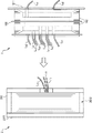
一次巻線102が巻数調整用巻線1022を有していない場合は、例えば、図20に示すように、第1のコイルボビン101の外周側面に凹溝1012の第2の凹溝1014を除去した形状の凹溝1019(第1の凹溝1013と実質的に同じ)を設け、その凹溝1019の底面1019Bに1又は2以上の分割壁1018を垂直に突設するとよい。
When the primary winding 102 does not have the winding number adjusting winding 1022, for example, as shown in FIG. 20, the
図20(a)は、凹溝1019の底面1019Bの中央に分割壁1018を1枚だけ設けた例である。また、図20(b)は、同図(a)において、凹溝1019の両内壁面1019Aを底面1019Bに対して垂直にしたものである。
FIG. 20A shows an example in which only one
これらの場合は、上述した主要巻線1021の分割巻線1021aを第1の凹溝1013の第1の空間に層状に整列巻きし、分割巻線1021bを第1の凹溝1013の第2の空間に層状に整列巻きする方法と同様の方法で、一次巻線102を2つに分割し、一方を凹溝1019の第1の空間に層状に整列巻きし、他方を凹溝1019の第2の空間に層状に整列巻きすればよい。
In these cases, the split winding 1021a of the main winding 1021 described above is aligned and wound in a layered manner in the first space of the first
第1の実施の形態では、分割巻線1021aの両引出線Ld1,Ld2と分割巻線1021bの両引出線Le1,Le2をボビン本体1011の外部に引き出し、分割巻線1021aと分割巻線1021bを直列接続するようにしたが、分割壁1018の上端の適所に切り欠きを設け、一次巻線102を凹溝1019の第1の空間に底面1019Bから層状に整列巻きした後、切り欠きから凹溝1019の第2の空間の底面1019Bに整列巻きの位置を移動させて当該第2の空間に層状に整列巻きするようにしてもよい。
In the first embodiment, both lead lines L d1 and L d2 of the split winding 1021a and both lead lines L e1 and L e2 of the split winding 1021b are drawn outside the
図20(c)は、同図(b)において、凹溝1019の底面1019Bに2枚の分割壁1018を設け、凹溝1019の空間を3つに分けた例である。この例では、2枚の分割壁1018の上端の適所に切り欠き1018Aが設けられている。
FIG. 20C is an example in which two
この例では、一次巻線102を凹溝1019の第1の空間(図20(c)では、左側の空間)に底面1019Bから層状に整列巻きした後、左側の分割壁1018の切り欠き1018Aから凹溝1019の第2の空間(図20(c)では、中央の空間)の底面1019Bに整列巻きの位置を移動させて当該第2の空間に層状に整列巻きし、さらに右側の分割壁1018の切り欠き1018Aから凹溝1019の第3の空間(図20(c)では、右側の空間)の底面1019Bに整列巻きの位置を移動させて当該第3の空間に層状に整列巻きするようにすればよい。
In this example, the primary winding 102 is aligned and wound in layers from the bottom surface 1019B in the first space of the concave groove 1019 (left space in FIG. 20C), and then from the
第1,第2の実施の形態に示す変圧器A1,A2は、コイル部Bの一方の脚部に円筒状の鉄心Cを1個だけ設けた構造を有していたが、変圧器は、コイル部Bの2つの脚部にそれぞれ円筒状の鉄心Cを設けた構造であってもよい。この場合は、巻線引出部1015A〜1015F,1015A’〜1015G’を第1のコイルボビン101,101’の短辺の部分に設ければよく、巻線引出部2013を第2のコイルボビン201の短辺の部分に設ければよい。
The transformers A1 and A2 shown in the first and second embodiments have a structure in which only one cylindrical iron core C is provided on one leg part of the coil part B. The structure which provided the cylindrical iron core C in the two leg parts of the coil part B may be sufficient. In this case, the winding
第1,第2の実施の形態では、変圧器A1,A2に用いられるコイル部Bについて説明したが、本発明は、変圧器に限定されるものではなく、同一の構造を有するコイル部を用いる静止誘導機器に広く利用することができる。 In the first and second embodiments, the coil part B used for the transformers A1 and A2 has been described. However, the present invention is not limited to the transformer, and uses a coil part having the same structure. It can be widely used for static induction equipment.
A1,A2 変圧器
B コイル部
C 鉄心
1 一次コイル
101,101’ 第1のコイルボビン
1011,1011’ ボビン本体
1012,1012’ 凹溝
1013 第1の凹溝
1013A 第1の凹溝の内壁面
1013B 第1の凹溝の底面
1014 第2の凹溝
1014A 第1の凹溝の内壁面
1014B 第2の凹溝の底面
1015A〜1015F 切り欠き部(巻線引出部)
1015A’〜1015G’ 切り欠き部(巻線引出部)
1016 第1のガイド溝
1017 第2のガイド溝
1018 分割壁
1018A 切り欠き
1019 凹溝
1019B 底面
102 一次巻線
1021 主要巻線(第1の巻線)
1022 巻数調整用巻線(第2の巻線)
1022a,1022b,1022c 小巻線
2 二次コイル
201 第2のコイルボビン
2011 ボビン本体
2012 凹溝
2012A 内壁面
2012B 底面
2013 切り欠き部(巻線引出部)
2014 ガイド溝
202 二次巻線
BS1(+),BS1(−) 一次ブッシング
BS2(+),BS2(−),BS2(G) 二次ブッシング
La1,La2,Lb1,Lb2,Lc1,Lc2,Ld1,Ld2,Le1,Le2 一次コイルの引出線
Lf1,Lf2,Lf3 二次コイルの引出線
Q0,Q1,Q2 一次ブッシング中継端子
P1〜P5 タップ端子
Pc コモン端子
T0〜T5 接続点
TL,TL’ タップ切換器
TC 切換片
A1, A2 Transformer B Coil part
1015A 'to 1015G' Notch (winding lead)
1016
1022 Winding adjustment winding (second winding)
1022a, 1022b, 1022c Small winding 2
2014
Claims (5)
前記ボビン本体の外周側面に形成された凹溝と、
を備え、前記凹溝に巻線を層状に整列巻きしてコイルが製作されるコイルボビンであって、
前記凹溝は、所定の断面形状を有する第1の凹溝と、当該第1の凹溝の底面に穿設された、所定の断面形状を有する第2の凹溝とを有しており、
前記第2の凹溝の底面には、当該第2の凹溝と前記第1の凹溝を幅方向に第1の空間と第2の空間に分割するように、1つの分割壁が垂直に形成されており、
前記巻線は、巻数の主要部を構成する主要巻線と、巻数の調整部を構成する巻数調整用巻線とを有しており、
前記第2の凹溝の第1の空間に臨む側壁には、前記巻数調整用巻線の両端部を前記ボビン本体から引き出すための第1の巻線引出部が設けられており、
前記第1の凹溝の両側壁には、前記主要巻線の両端部をそれぞれ前記ボビン本体から引き出すための第2の巻線引出部が設けられており、
前記巻線は、前記巻数調整用巻線が前記第2の凹溝の第1の空間に層状に整列巻きされた後、前記主要巻線が前記第1の凹溝の第1の空間と第2の空間に亘って層状に整列巻きされ、前記第1の巻線引出部から引き出された前記巻数調整用巻線の一方端と前記第2の巻線引出部から引き出された前記主要巻線の一方端とが前記ボビン本体の外部でタップ端子を介して直列に接続され、
前記第2の凹溝の両内壁面は、当該第2の凹溝の底面に対して垂直であり、
前記第2の凹溝の第1の空間における幅wは、次式で示されるように設定されている、コイルボビン。
w=φ×n/(2×k)+φ/2
(式中、φは巻線の線径であり、2×kは前記巻数調整用巻線の層数であり(kは正の整数)、nは前記巻数調整用巻線の巻数である。) The bobbin body,
A concave groove formed on the outer peripheral side surface of the bobbin body;
A coil bobbin in which a coil is manufactured by winding windings in layers in the concave groove,
The concave groove has a first concave groove having a predetermined cross-sectional shape, and a second concave groove having a predetermined cross-sectional shape formed in the bottom surface of the first concave groove,
One dividing wall is perpendicular to the bottom surface of the second groove so as to divide the second groove and the first groove into a first space and a second space in the width direction. Formed,
The winding has a main winding that constitutes a main part of the number of turns, and a winding adjustment coil that constitutes an adjustment part of the number of turns,
The side wall facing the first space of the second concave groove is provided with a first winding lead portion for pulling out both ends of the winding number adjustment winding from the bobbin body,
On both side walls of the first concave groove, second winding lead portions for pulling out both end portions of the main winding from the bobbin body are provided.
In the winding, after the winding adjustment winding is aligned and wound in layers in the first space of the second groove, the main winding is connected to the first space of the first groove and the first space. The main windings are aligned and wound in layers over two spaces, and are drawn from one end of the winding number adjustment winding drawn from the first winding lead and the second winding lead. Is connected in series via a tap terminal outside the bobbin body,
Both inner wall surfaces of the second groove are perpendicular to the bottom surface of the second groove,
A coil bobbin in which the width w in the first space of the second concave groove is set as shown by the following equation .
w = φ × n / (2 × k) + φ / 2
(Where, φ is the wire diameter of the winding, 2 × k is the number of layers of the winding adjustment winding (k is a positive integer), and n is the number of turns of the winding adjustment winding. )
前記第1の巻線引出部は、前記複数の小巻線の各々に対応して設けられた複数の巻線引出部を有し、
前記複数の小巻線は、前記第2の凹溝に層状に巻回されるとともに、各小巻線の両端部が前記第1の巻線引出部の対応する巻線引出部から引き出され、ボビン本体の外部でタップ端子を介して直列に接続され、
前記各小巻線の巻数は同じであり、
前記第2の凹溝の第1の空間における幅wは、次式で示されるように設定されている、請求項1又は2に記載のコイルボビン。
w=φ×n s /(2×k s )+φ/2
(式中、2×k s は前記小巻線の層数であり(k s は正の整数)、n s は前記小巻線の巻数である。) The winding number adjustment winding has a plurality of small windings connected in series with each other and having a smaller number of turns than the winding,
The first winding lead portion has a plurality of winding lead portions provided corresponding to each of the plurality of small windings,
The plurality of small windings are wound in layers in the second concave groove, and both end portions of each small winding are drawn from corresponding winding lead portions of the first winding lead portion, Connected in series via the tap terminal outside the bobbin body ,
The number of turns of each small winding is the same,
The coil bobbin according to claim 1 or 2 , wherein a width w of the second concave groove in the first space is set as represented by the following equation .
w = φ × n s / (2 × k s ) + φ / 2
(In the formula, 2 × k s is the number of layers of the small winding (k s is a positive integer), and n s is the number of turns of the small winding.)
請求項1乃至3のいずれかに記載のコイルボビンの凹溝に巻線を層状に整列巻きして成形されている、ことを特徴とするコイル。 A coil used in a stationary induction device,
A coil, wherein the coil bobbin according to any one of claims 1 to 3 is formed by winding a winding in a layered manner in the groove of the coil bobbin.
Priority Applications (1)
| Application Number | Priority Date | Filing Date | Title |
|---|---|---|---|
| JP2015164715A JP6576740B2 (en) | 2015-08-24 | 2015-08-24 | Coil bobbin, coil and transformer provided with the coil |
Applications Claiming Priority (1)
| Application Number | Priority Date | Filing Date | Title |
|---|---|---|---|
| JP2015164715A JP6576740B2 (en) | 2015-08-24 | 2015-08-24 | Coil bobbin, coil and transformer provided with the coil |
Publications (3)
| Publication Number | Publication Date |
|---|---|
| JP2017045750A JP2017045750A (en) | 2017-03-02 |
| JP2017045750A5 JP2017045750A5 (en) | 2018-06-21 |
| JP6576740B2 true JP6576740B2 (en) | 2019-09-18 |
Family
ID=58210367
Family Applications (1)
| Application Number | Title | Priority Date | Filing Date |
|---|---|---|---|
| JP2015164715A Active JP6576740B2 (en) | 2015-08-24 | 2015-08-24 | Coil bobbin, coil and transformer provided with the coil |
Country Status (1)
| Country | Link |
|---|---|
| JP (1) | JP6576740B2 (en) |
Families Citing this family (3)
| Publication number | Priority date | Publication date | Assignee | Title |
|---|---|---|---|---|
| CN108198683A (en) * | 2017-12-12 | 2018-06-22 | 深圳市索源科技有限公司 | A kind of transformer framework |
| JP7368956B2 (en) * | 2019-05-16 | 2023-10-25 | 株式会社ダイヘン | Transformer and bobbin |
| JP7514995B1 (en) | 2023-11-10 | 2024-07-11 | 株式会社東光高岳 | Transformers |
Family Cites Families (5)
| Publication number | Priority date | Publication date | Assignee | Title |
|---|---|---|---|---|
| JPS5628746Y2 (en) * | 1977-03-31 | 1981-07-08 | ||
| JPS5678536U (en) * | 1979-11-22 | 1981-06-25 | ||
| JPH036805A (en) * | 1989-06-05 | 1991-01-14 | Toshiba Corp | Transformer with tap winding |
| JPH0436203U (en) * | 1990-07-25 | 1992-03-26 | ||
| JP3229512B2 (en) * | 1994-05-30 | 2001-11-19 | 株式会社西本合成販売 | Transformers and coil bobbins for transformers |
-
2015
- 2015-08-24 JP JP2015164715A patent/JP6576740B2/en active Active
Also Published As
| Publication number | Publication date |
|---|---|
| JP2017045750A (en) | 2017-03-02 |
Similar Documents
| Publication | Publication Date | Title |
|---|---|---|
| TWI389147B (en) | Conductive winding structure and magnetic device using same | |
| JP6576740B2 (en) | Coil bobbin, coil and transformer provided with the coil | |
| EP2846335A2 (en) | Transformer | |
| JP3196424U (en) | Bobbin configuration with coupling adjustment winding groove | |
| JP6607809B2 (en) | Coil bobbin, coil and transformer provided with the coil | |
| JP6607808B2 (en) | Coil bobbin, coil and transformer provided with the coil | |
| JP2012064626A (en) | Transformer | |
| JP2019134126A (en) | Stationary induction apparatus | |
| KR100881364B1 (en) | Current transformer for power supply and manufacturing method thereof | |
| JP6576753B2 (en) | Coil bobbin, coil and transformer provided with the coil | |
| WO2018070198A1 (en) | Transformer and power converter provided with same | |
| US9583252B2 (en) | Transformer | |
| JP5680327B2 (en) | Split winding transformer | |
| JP7063579B2 (en) | Transformers and coil bobbins | |
| JP7029920B2 (en) | Transformer | |
| US8487732B2 (en) | Coil transformer composed of unit configuration | |
| JP2008205212A (en) | Transformer | |
| JP6576734B2 (en) | Coil bobbin, coil and transformer provided with the coil | |
| US10283260B2 (en) | Transformer for reducing eddy current losses of coil | |
| US20220189687A1 (en) | Leakage transformer | |
| JP6437851B2 (en) | Coil bobbin, coil and transformer provided with the coil | |
| WO2015045560A1 (en) | Coupling coil structure and transformer | |
| EP3544033B1 (en) | Electromagnetic induction device having a low losses winding | |
| KR101427633B1 (en) | Power trasformer | |
| KR101631182B1 (en) | Transformer for high space factor |
Legal Events
| Date | Code | Title | Description |
|---|---|---|---|
| A521 | Request for written amendment filed |
Free format text: JAPANESE INTERMEDIATE CODE: A523 Effective date: 20180510 |
|
| A621 | Written request for application examination |
Free format text: JAPANESE INTERMEDIATE CODE: A621 Effective date: 20180510 |
|
| A977 | Report on retrieval |
Free format text: JAPANESE INTERMEDIATE CODE: A971007 Effective date: 20190131 |
|
| A131 | Notification of reasons for refusal |
Free format text: JAPANESE INTERMEDIATE CODE: A131 Effective date: 20190305 |
|
| A521 | Request for written amendment filed |
Free format text: JAPANESE INTERMEDIATE CODE: A523 Effective date: 20190416 |
|
| TRDD | Decision of grant or rejection written | ||
| A01 | Written decision to grant a patent or to grant a registration (utility model) |
Free format text: JAPANESE INTERMEDIATE CODE: A01 Effective date: 20190819 |
|
| A61 | First payment of annual fees (during grant procedure) |
Free format text: JAPANESE INTERMEDIATE CODE: A61 Effective date: 20190821 |
|
| R150 | Certificate of patent or registration of utility model |
Ref document number: 6576740 Country of ref document: JP Free format text: JAPANESE INTERMEDIATE CODE: R150 |
|
| R250 | Receipt of annual fees |
Free format text: JAPANESE INTERMEDIATE CODE: R250 |
|
| R250 | Receipt of annual fees |
Free format text: JAPANESE INTERMEDIATE CODE: R250 |
|
| R250 | Receipt of annual fees |
Free format text: JAPANESE INTERMEDIATE CODE: R250 |