JP6576460B2 - Induction heating cooker - Google Patents

Induction heating cooker Download PDF

Info

Publication number
JP6576460B2
JP6576460B2 JP2017546371A JP2017546371A JP6576460B2 JP 6576460 B2 JP6576460 B2 JP 6576460B2 JP 2017546371 A JP2017546371 A JP 2017546371A JP 2017546371 A JP2017546371 A JP 2017546371A JP 6576460 B2 JP6576460 B2 JP 6576460B2
Authority
JP
Japan
Prior art keywords
unit
induction heating
period
wireless communication
external device
Prior art date
Legal status (The legal status is an assumption and is not a legal conclusion. Google has not performed a legal analysis and makes no representation as to the accuracy of the status listed.)
Active
Application number
JP2017546371A
Other languages
Japanese (ja)
Other versions
JPWO2017068716A1 (en
Inventor
岳秋 飯田
岳秋 飯田
雄一郎 伊藤
雄一郎 伊藤
吉野 勇人
勇人 吉野
Current Assignee (The listed assignees may be inaccurate. Google has not performed a legal analysis and makes no representation or warranty as to the accuracy of the list.)
Mitsubishi Electric Home Appliance Co Ltd
Mitsubishi Electric Corp
Original Assignee
Mitsubishi Electric Home Appliance Co Ltd
Mitsubishi Electric Corp
Priority date (The priority date is an assumption and is not a legal conclusion. Google has not performed a legal analysis and makes no representation as to the accuracy of the date listed.)
Filing date
Publication date
Application filed by Mitsubishi Electric Home Appliance Co Ltd, Mitsubishi Electric Corp filed Critical Mitsubishi Electric Home Appliance Co Ltd
Publication of JPWO2017068716A1 publication Critical patent/JPWO2017068716A1/en
Application granted granted Critical
Publication of JP6576460B2 publication Critical patent/JP6576460B2/en
Active legal-status Critical Current
Anticipated expiration legal-status Critical

Links

Images

Classifications

    • HELECTRICITY
    • H05ELECTRIC TECHNIQUES NOT OTHERWISE PROVIDED FOR
    • H05BELECTRIC HEATING; ELECTRIC LIGHT SOURCES NOT OTHERWISE PROVIDED FOR; CIRCUIT ARRANGEMENTS FOR ELECTRIC LIGHT SOURCES, IN GENERAL
    • H05B6/00Heating by electric, magnetic or electromagnetic fields
    • H05B6/02Induction heating
    • H05B6/06Control, e.g. of temperature, of power
    • H05B6/062Control, e.g. of temperature, of power for cooking plates or the like
    • HELECTRICITY
    • H05ELECTRIC TECHNIQUES NOT OTHERWISE PROVIDED FOR
    • H05BELECTRIC HEATING; ELECTRIC LIGHT SOURCES NOT OTHERWISE PROVIDED FOR; CIRCUIT ARRANGEMENTS FOR ELECTRIC LIGHT SOURCES, IN GENERAL
    • H05B6/00Heating by electric, magnetic or electromagnetic fields
    • H05B6/02Induction heating
    • H05B6/10Induction heating apparatus, other than furnaces, for specific applications
    • H05B6/12Cooking devices
    • H05B6/1209Cooking devices induction cooking plates or the like and devices to be used in combination with them
    • H05B6/1245Cooking devices induction cooking plates or the like and devices to be used in combination with them with special coil arrangements
    • HELECTRICITY
    • H05ELECTRIC TECHNIQUES NOT OTHERWISE PROVIDED FOR
    • H05BELECTRIC HEATING; ELECTRIC LIGHT SOURCES NOT OTHERWISE PROVIDED FOR; CIRCUIT ARRANGEMENTS FOR ELECTRIC LIGHT SOURCES, IN GENERAL
    • H05B1/00Details of electric heating devices
    • H05B1/02Automatic switching arrangements specially adapted to apparatus ; Control of heating devices
    • H05B1/0202Switches
    • HELECTRICITY
    • H05ELECTRIC TECHNIQUES NOT OTHERWISE PROVIDED FOR
    • H05BELECTRIC HEATING; ELECTRIC LIGHT SOURCES NOT OTHERWISE PROVIDED FOR; CIRCUIT ARRANGEMENTS FOR ELECTRIC LIGHT SOURCES, IN GENERAL
    • H05B1/00Details of electric heating devices
    • H05B1/02Automatic switching arrangements specially adapted to apparatus ; Control of heating devices
    • H05B1/0227Applications
    • H05B1/0252Domestic applications
    • H05B1/0258For cooking
    • H05B1/0261For cooking of food
    • H05B1/0266Cooktops
    • HELECTRICITY
    • H05ELECTRIC TECHNIQUES NOT OTHERWISE PROVIDED FOR
    • H05BELECTRIC HEATING; ELECTRIC LIGHT SOURCES NOT OTHERWISE PROVIDED FOR; CIRCUIT ARRANGEMENTS FOR ELECTRIC LIGHT SOURCES, IN GENERAL
    • H05B6/00Heating by electric, magnetic or electromagnetic fields
    • H05B6/02Induction heating
    • H05B6/06Control, e.g. of temperature, of power
    • H05B6/062Control, e.g. of temperature, of power for cooking plates or the like
    • H05B6/065Control, e.g. of temperature, of power for cooking plates or the like using coordinated control of multiple induction coils
    • HELECTRICITY
    • H05ELECTRIC TECHNIQUES NOT OTHERWISE PROVIDED FOR
    • H05BELECTRIC HEATING; ELECTRIC LIGHT SOURCES NOT OTHERWISE PROVIDED FOR; CIRCUIT ARRANGEMENTS FOR ELECTRIC LIGHT SOURCES, IN GENERAL
    • H05B6/00Heating by electric, magnetic or electromagnetic fields
    • H05B6/02Induction heating
    • H05B6/10Induction heating apparatus, other than furnaces, for specific applications
    • H05B6/12Cooking devices
    • H05B6/1209Cooking devices induction cooking plates or the like and devices to be used in combination with them
    • H05B6/1236Cooking devices induction cooking plates or the like and devices to be used in combination with them adapted to induce current in a coil to supply power to a device and electrical heating devices powered in this way
    • FMECHANICAL ENGINEERING; LIGHTING; HEATING; WEAPONS; BLASTING
    • F24HEATING; RANGES; VENTILATING
    • F24CDOMESTIC STOVES OR RANGES ; DETAILS OF DOMESTIC STOVES OR RANGES, OF GENERAL APPLICATION
    • F24C7/00Stoves or ranges heated by electric energy
    • F24C7/06Arrangement or mounting of electric heating elements
    • F24C7/067Arrangement or mounting of electric heating elements on ranges
    • FMECHANICAL ENGINEERING; LIGHTING; HEATING; WEAPONS; BLASTING
    • F24HEATING; RANGES; VENTILATING
    • F24CDOMESTIC STOVES OR RANGES ; DETAILS OF DOMESTIC STOVES OR RANGES, OF GENERAL APPLICATION
    • F24C7/00Stoves or ranges heated by electric energy
    • F24C7/08Arrangement or mounting of control or safety devices
    • F24C7/082Arrangement or mounting of control or safety devices on ranges, e.g. control panels, illumination
    • F24C7/083Arrangement or mounting of control or safety devices on ranges, e.g. control panels, illumination on tops, hot plates
    • HELECTRICITY
    • H05ELECTRIC TECHNIQUES NOT OTHERWISE PROVIDED FOR
    • H05BELECTRIC HEATING; ELECTRIC LIGHT SOURCES NOT OTHERWISE PROVIDED FOR; CIRCUIT ARRANGEMENTS FOR ELECTRIC LIGHT SOURCES, IN GENERAL
    • H05B2213/00Aspects relating both to resistive heating and to induction heating, covered by H05B3/00 and H05B6/00
    • H05B2213/06Cook-top or cookware capable of communicating with each other

Description

本発明は、電磁誘導により被加熱物を加熱する誘導加熱調理器に関する。   The present invention relates to an induction heating cooker that heats an object to be heated by electromagnetic induction.

従来、誘導加熱調理器の出力は、誘導加熱調理器本体に設置された操作部で、投入火力すなわち投入電力の選択、または湯沸かしモード、揚げ物モードなどの調理メニューの選択を受け付け、受け付けた選択結果に応じて制御される。   Conventionally, the output of the induction heating cooker is the operation unit installed in the induction heating cooker body, accepting selection of input heating power, that is, input power, or selection of cooking menu such as a kettle mode, fried food mode, etc. It is controlled according to.

これに対し、利便性向上のため、誘導加熱調理器の出力を、外部機器を用いて無線通信により遠隔操作する技術、および他の家電機器と無線通信により連携して自動制御する技術が開発されている。   On the other hand, in order to improve convenience, a technology for remotely controlling the output of the induction heating cooker by wireless communication using an external device and a technology for automatically controlling in cooperation with other home appliances by wireless communication have been developed. ing.

例として、特許文献1に開示されているように、外部機器として無線通信機能を有する携帯端末を用い、携帯端末との無線通信を利用して遠隔操作により誘導加熱調理器の投入電力を制御する方法がある。   As an example, as disclosed in Patent Document 1, a portable terminal having a wireless communication function is used as an external device, and the input power of the induction heating cooker is controlled by remote operation using wireless communication with the portable terminal. There is a way.

特開2014−202407号公報JP 2014-202407 A

誘導加熱調理器は、天板の下方に配置された加熱コイルで高周波磁束を発生させ、加熱を行う。このとき、加熱コイルからは漏洩磁束が発生する。このため、無線通信を利用して遠隔操作により誘導加熱調理器の電力投入をする場合に、漏洩磁束が外部機器との間で送信または受信される無線信号に干渉し、無線通信の品質が劣化するという問題がある。   An induction heating cooker generates high-frequency magnetic flux with a heating coil disposed below the top plate and performs heating. At this time, a leakage magnetic flux is generated from the heating coil. For this reason, when the induction heating cooker is turned on by remote control using wireless communication, the leakage magnetic flux interferes with the wireless signal transmitted or received with the external device, and the quality of the wireless communication is deteriorated. There is a problem of doing.

本発明は、上記に鑑みてなされたものであって、外部機器との間で送信または受信される無線信号に対する漏洩磁束による干渉を抑制することができる誘導加熱調理器を得ることを目的とする。   This invention is made in view of the above, Comprising: It aims at obtaining the induction heating cooking appliance which can suppress the interference by the leakage magnetic flux with respect to the radio signal transmitted or received between external devices. .

上述した課題を解決し、目的を達成するために、本発明にかかる誘導加熱調理器は、外部機器と無線通信を実行可能な誘導加熱調理器であり、誘導加熱調理器は被加熱物の加熱のために用いられ、被加熱物を誘導加熱する加熱部と、加熱部に電力を出力する駆動回路と、外部機器との間の無線通信に周期性が有る場合、外部機器との間の無線通信の周期を算出し、周期に基づいて第1の期間および第2の期間を予測し、予測した結果に基づいて駆動回路から出力される電力を変更する制御部とを備える。第1の期間において駆動回路から出力される電力は、第2の期間において駆動回路から出力される電力より小さく、第1の期間は外部機器と無線通信を実行する期間であり、第2の期間は外部機器と無線通信を実行しない期間である。 In order to solve the above-described problems and achieve the object, an induction heating cooker according to the present invention is an induction heating cooker capable of performing wireless communication with an external device, and the induction heating cooker heats an object to be heated. If the wireless communication between the external device and the heating unit for induction heating of the object to be heated, the drive circuit that outputs power to the heating unit, and the external device has periodicity, the wireless A control unit that calculates a communication period, predicts the first period and the second period based on the period, and changes the power output from the drive circuit based on the predicted result . The power output from the drive circuit in the first period is smaller than the power output from the drive circuit in the second period, and the first period is a period for performing wireless communication with the external device, and the second period Is a period during which wireless communication with an external device is not performed.

本発明にかかる誘導加熱調理器は、遠隔操作のための無線信号に対する漏洩磁束による干渉を抑制することができるという効果を奏する。   INDUSTRIAL APPLICABILITY The induction heating cooker according to the present invention has an effect that it is possible to suppress interference due to leakage magnetic flux to a radio signal for remote operation.

実施の形態1にかかる誘導加熱調理器の分解斜視図The exploded perspective view of the induction heating cooking appliance concerning Embodiment 1 実施の形態1にかかる誘導加熱調理器の駆動回路の構成例を示す図The figure which shows the structural example of the drive circuit of the induction heating cooking appliance concerning Embodiment 1. FIG. 実施の形態1のIGBTに制御部から入力される制御信号の一例を示す図The figure which shows an example of the control signal input from IGBT to the IGBT of the first embodiment 実施の形態1のIGBTに制御部から入力される制御信号の別の一例を示す図The figure which shows another example of the control signal input into IGBT of Embodiment 1 from a control part. 実施の形態1にかかる誘導加熱調理器の別の駆動回路の例を示す図The figure which shows the example of another drive circuit of the induction heating cooking appliance concerning Embodiment 1. FIG. 実施の形態1の図5に示したIGBTのオン/オフを制御する制御信号の例を示す図FIG. 5 is a diagram illustrating an example of a control signal for controlling on / off of the IGBT illustrated in FIG. 5 according to the first embodiment. 実施の形態1の処理回路の構成例を示す図FIG. 3 illustrates a configuration example of a processing circuit according to the first embodiment. 実施の形態1の制御回路の構成例を示す図FIG. 3 is a diagram illustrating a configuration example of a control circuit according to the first embodiment. 実施の形態1の外部機器の構成例を示す図FIG. 3 illustrates a configuration example of an external device according to the first embodiment. 実施の形態1にかかる誘導加熱調理器の制御部の構成例を示す図The figure which shows the structural example of the control part of the induction heating cooking appliance concerning Embodiment 1. FIG. 実施の形態1の駆動回路が第一の加熱部へ供給する高周波電力と、通信部が無線通信を行う期間との関係の一例を示す図The figure which shows an example of the relationship between the high frequency electric power which the drive circuit of Embodiment 1 supplies to a 1st heating part, and the period when a communication part performs radio | wireless communication. 実施の形態1の駆動回路が第一の加熱部へ供給する高周波電力と、通信部が無線通信を行う期間との関係の別の一例を示す図The figure which shows another example of the relationship between the high frequency electric power which the drive circuit of Embodiment 1 supplies to a 1st heating part, and the period when a communication part performs radio | wireless communication. 実施の形態1の電力変更制御手順の一例を示すフローチャートFlowchart showing an example of the power change control procedure of the first embodiment 実施の形態1の無線通信の休止期間で出力電力を上昇させる場合の駆動回路が供給する高周波電力の一例を示す図The figure which shows an example of the high frequency electric power which a drive circuit supplies when raising output electric power in the idle period of the wireless communication of Embodiment 1 実施の形態2にかかる誘導加熱調理器の制御部の構成例を示す図The figure which shows the structural example of the control part of the induction heating cooking appliance concerning Embodiment 2. FIG. 実施の形態2において駆動回路が供給する高周波電力と、通信部が無線通信を行う期間との関係の一例を示す図FIG. 9 is a diagram illustrating an example of a relationship between high-frequency power supplied by a driving circuit and a period in which a communication unit performs wireless communication in Embodiment 2. 実施の形態2の通信制御手順の一例を示すフローチャートFlowchart illustrating an example of a communication control procedure according to the second embodiment

以下に、本発明の実施の形態にかかる誘導加熱調理器を図面に基づいて詳細に説明する。なお、この実施の形態によりこの発明が限定されるものではない。   Below, the induction heating cooking appliance concerning the embodiment of the invention is explained in detail based on a drawing. Note that the present invention is not limited to the embodiments.

実施の形態1.
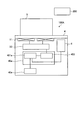
図1は、本発明の実施の形態1にかかる誘導加熱調理器の分解斜視図である。本実施の形態の誘導加熱調理器100は、外部機器200と無線通信により通信可能である。図1に示すように、本実施の形態の誘導加熱調理器100は、第一の加熱部11、第二の加熱部12および第三の加熱部13を備える。第一の加熱部11、第二の加熱部12および第三の加熱部13は、本体筐体7に収容される。また、誘導加熱調理器100は、鍋などの被加熱物5を載置可能な天板4を有している。以下、本体筐体7および本体筐体7に収容される各部、すなわち誘導加熱調理器100のうち天板4を除く部分を、本体と呼ぶこともある。
Embodiment 1 FIG.
FIG. 1 is an exploded perspective view of the induction heating cooker according to the first embodiment of the present invention. Induction heating cooker 100 of the present embodiment can communicate with external device 200 by wireless communication. As shown in FIG. 1, the induction heating cooker 100 of the present embodiment includes a first heating unit 11, a second heating unit 12, and a third heating unit 13. The first heating unit 11, the second heating unit 12, and the third heating unit 13 are accommodated in the main body housing 7. Moreover, the induction heating cooking appliance 100 has the top plate 4 which can mount the to-be-heated objects 5, such as a pan. Hereinafter, the main body casing 7 and each part accommodated in the main body casing 7, that is, the portion excluding the top plate 4 in the induction heating cooker 100 may be referred to as a main body.

天板4は、金属で構成される金属負荷である被加熱物を誘導加熱するための加熱口として、第一の加熱口1、第二の加熱口2および第三の加熱口3を備える。第一の加熱口1、第二の加熱口2および第三の加熱口3は、第一の加熱部11、第二の加熱部12および第三の加熱部13の加熱範囲にそれぞれ対応する位置に設けられ、各々が被加熱物を載置可能である。各加熱口に載置された被加熱物は、各加熱口に対応する加熱部により誘導加熱される。図1では、負荷として被加熱物5が天板4の第一の加熱口1に載置された例を示している。   The top plate 4 includes a first heating port 1, a second heating port 2, and a third heating port 3 as heating ports for inductively heating an object to be heated which is a metal load made of metal. The first heating port 1, the second heating port 2, and the third heating port 3 correspond to the heating ranges of the first heating unit 11, the second heating unit 12, and the third heating unit 13, respectively. Each of which can place an object to be heated. The object to be heated placed on each heating port is induction-heated by a heating unit corresponding to each heating port. FIG. 1 shows an example in which the object to be heated 5 is placed on the first heating port 1 of the top plate 4 as a load.

図1に示した例では、本体の手前側に左右に並べて第一の加熱部11と第二の加熱部12が設けられ、本体の奥側ほぼ中央に第三の加熱部13が設けられている。なお、手前とは、誘導加熱調理器100を操作者が利用する際に操作者が位置する側であり、図1の紙面の左下側である。なお、各加熱口の配置はこれに限るものではない。例えば、3つの加熱口を概略直線状に横に並べて配置しても良い。また、第一の加熱部11の中心と第二の加熱部12の中心との奥行き方向の位置が異なるように配置しても良い。また、本実施の形態1では3つの加熱部が設けられているが、加熱部の数は3つに限定されず、1つまたは2つであってもよく、4つ以上であってもよい。天板4には、加熱部の数に応じた加熱口が設けられる。   In the example shown in FIG. 1, a first heating unit 11 and a second heating unit 12 are provided side by side on the front side of the main body, and a third heating unit 13 is provided at substantially the center on the back side of the main body. Yes. Note that the near side is the side on which the operator is positioned when the operator uses the induction heating cooker 100, and is the lower left side of the page of FIG. In addition, arrangement | positioning of each heating port is not restricted to this. For example, three heating ports may be arranged side by side in a substantially straight line. Moreover, you may arrange | position so that the position of the depth direction of the center of the 1st heating part 11 and the center of the 2nd heating part 12 may differ. In the first embodiment, three heating units are provided, but the number of heating units is not limited to three, and may be one or two, or four or more. . The top plate 4 is provided with heating ports corresponding to the number of heating units.

天板4は、全体が耐熱強化ガラス、結晶化ガラス等の赤外線を透過する材料で構成されており、誘導加熱調理器100の本体筐体7の上面の開口外周との間にゴム製パッキン、またはシール材、またはこれらの組み合わせを介して水密状態に固定される。天板4には、第一の加熱部11、第二の加熱部12、および第三の加熱部13のそれぞれの加熱範囲、すなわち各加熱口を示す範囲に、被加熱物の大まかな載置位置を示す円形の表示、すなわち鍋位置表示が、塗料の塗布または印刷等により形成されている。   The top plate 4 is entirely made of a material that transmits infrared rays, such as heat-resistant tempered glass, crystallized glass, and the like, and a rubber packing is provided between the outer periphery of the upper surface of the main body housing 7 of the induction heating cooker 100, Alternatively, it is fixed in a watertight state through a sealing material or a combination thereof. On the top plate 4, the object to be heated is roughly placed in the heating range of each of the first heating unit 11, the second heating unit 12, and the third heating unit 13, that is, the range indicating each heating port. A circular display indicating the position, that is, a pan position display is formed by coating or printing of paint.

天板4には、第一の加熱部11、第二の加熱部12、および第三の加熱部13で被加熱物を加熱する際の投入火力すなわち投入電力、および調理メニューの設定を受け付けるための入力装置すなわち受信部として、操作部40a、操作部40b、および操作部40cが設けられている。調理メニューとしては、例えば、湯沸しモード、揚げ物モードなどが挙げられる。なお、以下、操作部40a、操作部40b、および操作部40cを操作部40と総称する場合がある。操作部40a、操作部40b、および操作部40cは、例えば、ボタン、レバー、タッチパネルである。   In order to receive the setting of the input heating power at the time of heating a to-be-heated object in the 1st heating part 11, the 2nd heating part 12, and the 3rd heating part 13, ie, input power, and a cooking menu in the top plate 4 As an input device, that is, a receiving unit, an operating unit 40a, an operating unit 40b, and an operating unit 40c are provided. Examples of the cooking menu include a water heating mode and a fried food mode. Hereinafter, the operation unit 40a, the operation unit 40b, and the operation unit 40c may be collectively referred to as the operation unit 40. The operation unit 40a, the operation unit 40b, and the operation unit 40c are, for example, buttons, levers, and touch panels.

天板4には、報知手段として、誘導加熱調理器100の動作状態、操作部40および外部機器200から入力された入力情報および制御内容、無線通信中の外部機器200に関する情報、無線通信の有無等を表示する表示部41a、表示部41b、および表示部41cが設けられている。すなわち、表示部41a,41b,41cは、誘導加熱調理器100の動作状態を示す情報、誘導加熱調理器100に対する設定情報、外部機器200から受信した制御信号に基づく情報、および外部機器200との間の通信状態を示す情報のうち少なくとも1つを表示する。表示部41a、表示部41b、および表示部41cは、例えば液晶モニタ、LED(light Emitting Diode)で構成される。以下、表示部41a、表示部41b、および表示部41cを表示部41と総称することがある。なお、本実施の形態における報知とは、画像および文字等による表示だけでなく音により、操作者に認識される動作を含んでいてもよい。   The top plate 4 has, as a notification means, an operating state of the induction heating cooker 100, input information and control contents input from the operation unit 40 and the external device 200, information on the external device 200 during wireless communication, presence / absence of wireless communication Etc., a display unit 41a, a display unit 41b, and a display unit 41c are provided. That is, the display units 41a, 41b, and 41c are information indicating the operation state of the induction heating cooker 100, setting information for the induction heating cooker 100, information based on a control signal received from the external device 200, and the external device 200. At least one of the information indicating the communication state is displayed. The display unit 41a, the display unit 41b, and the display unit 41c are configured by, for example, a liquid crystal monitor and an LED (light emitting diode). Hereinafter, the display unit 41a, the display unit 41b, and the display unit 41c may be collectively referred to as the display unit 41. Note that the notification in the present embodiment may include an operation recognized by the operator by sound as well as display by images and characters.

なお、図1の例では、操作部40a〜40cが加熱口ごとに設けられているが、加熱口の少なくとも2つ以上を一括した操作部を設けてもよい。また、同様に、加熱口の少なくとも2つ以上を一括した表示部を設けてもよい。また、操作部40と表示部41を兼ねた表示操作部43を設けてもよく、操作部および表示部の具体的な構成は特に限定するものではない。   In addition, in the example of FIG. 1, although the operation parts 40a-40c are provided for every heating opening, you may provide the operation part which bundled at least 2 or more of heating openings. Similarly, a display unit that collects at least two of the heating ports may be provided. In addition, a display operation unit 43 serving as the operation unit 40 and the display unit 41 may be provided, and the specific configurations of the operation unit and the display unit are not particularly limited.

天板4の下方であって本体筐体7の内部には、上述したように、第一の加熱部11、第二の加熱部12、および第三の加熱部13が設けられる。各々の加熱部は加熱コイルで構成されている。   As described above, the first heating unit 11, the second heating unit 12, and the third heating unit 13 are provided below the top plate 4 and inside the main body housing 7. Each heating unit is composed of a heating coil.

さらに、誘導加熱調理器100の本体筐体7の内部には、第一の加熱部11、第二の加熱部12、および第三の加熱部13の加熱コイルに電力を供給する駆動部50と、駆動部50を含め誘導加熱調理器100全体の動作を制御するための制御部45と、外部機器200との間での無線通信を実行する通信部6とが設けられている。   Furthermore, inside the main body casing 7 of the induction heating cooker 100, there is a drive unit 50 that supplies power to the heating coils of the first heating unit 11, the second heating unit 12, and the third heating unit 13. A control unit 45 for controlling the overall operation of the induction heating cooker 100 including the drive unit 50 and a communication unit 6 for performing wireless communication with the external device 200 are provided.

第一の加熱部11、第二の加熱部12、および第三の加熱部13を構成する各加熱コイルは、略円形の平面形状を有し、絶縁皮膜された任意の金属からなる導電線を円周方向に巻き付けることにより構成される。加熱コイルを構成する金属としては、例えば銅、アルミを用いることができる。誘導加熱調理器100では、駆動部50により高周波電力が各加熱コイルに供給されることで、誘導加熱動作が行われる。   Each of the heating coils constituting the first heating unit 11, the second heating unit 12, and the third heating unit 13 has a substantially circular planar shape, and has a conductive wire made of any metal with an insulating film. It is configured by winding in the circumferential direction. As the metal constituting the heating coil, for example, copper or aluminum can be used. In the induction heating cooker 100, the induction heating operation is performed by supplying high-frequency power to each heating coil by the driving unit 50.

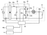
駆動部50は、各加熱部にそれぞれ対応する3つの駆動回路51を備える。図2は、実施の形態1にかかる誘導加熱調理器100の駆動回路51の構成例を示す図である。図2では、第一の加熱部11に対応する駆動回路51の構成例を示すが、各加熱部に対応する駆動回路は同一であってもよいし、加熱部ごとに異なっていてもよい。   The drive unit 50 includes three drive circuits 51 corresponding to the respective heating units. FIG. 2 is a diagram illustrating a configuration example of the drive circuit 51 of the induction heating cooker 100 according to the first embodiment. Although FIG. 2 shows a configuration example of the drive circuit 51 corresponding to the first heating unit 11, the drive circuit corresponding to each heating unit may be the same or different for each heating unit.

駆動回路51は、図2に示すように、直流電源回路22、インバータ回路23、共振コンデンサ24、入力電流検出部25aおよび出力電流検出部25bを備える。   As shown in FIG. 2, the drive circuit 51 includes a DC power supply circuit 22, an inverter circuit 23, a resonance capacitor 24, an input current detection unit 25a, and an output current detection unit 25b.

入力電流検出部25aは、交流電源21から直流電源回路22へ入力される電流、すなわち駆動回路51へ入力される電流を検出し、検出した値すなわち入力電流値を示す電圧信号を制御部45へ出力する。交流電源21は、例えば商用交流電源である。   The input current detection unit 25a detects a current input from the AC power supply 21 to the DC power supply circuit 22, that is, a current input to the drive circuit 51, and outputs a detected value, that is, a voltage signal indicating the input current value to the control unit 45. Output. The AC power source 21 is, for example, a commercial AC power source.

直流電源回路22は、ダイオードブリッジ22a、リアクタ22b、平滑コンデンサ22cと、を備え、交流電源21から入力される交流電圧を直流電圧に変換して、インバータ回路23へ出力する。   The DC power supply circuit 22 includes a diode bridge 22a, a reactor 22b, and a smoothing capacitor 22c, converts an AC voltage input from the AC power supply 21 into a DC voltage, and outputs the DC voltage to the inverter circuit 23.

インバータ回路23は、スイッチング素子としてのIGBT(Insulated Gate Bipolar Transistor)23a、23bが直流電源回路22の出力に直列に接続された、いわゆるハーフブリッジ型のインバータである。インバータ回路23では、フライホイールダイオードとしてダイオード23c、23dがそれぞれIGBT23a、23bと並列に接続されている。インバータ回路23は、直流電源回路22から出力される直流電力を20kHz〜80kHz程度の高周波の交流電力、いわゆる高周波電力に変換して、加熱コイルである第一の加熱部11と共振コンデンサ24とからなる共振回路に供給する。   The inverter circuit 23 is a so-called half-bridge type inverter in which IGBTs (Insulated Gate Bipolar Transistors) 23 a and 23 b as switching elements are connected in series to the output of the DC power supply circuit 22. In the inverter circuit 23, diodes 23c and 23d as flywheel diodes are connected in parallel with the IGBTs 23a and 23b, respectively. The inverter circuit 23 converts the DC power output from the DC power supply circuit 22 into high-frequency AC power of about 20 kHz to 80 kHz, so-called high-frequency power, and from the first heating unit 11 that is a heating coil and the resonance capacitor 24. To the resonant circuit.

共振コンデンサ24は第一の加熱部11に直列接続されており、この共振回路は第一の加熱部11のインダクタンスおよび共振コンデンサ24の容量等に応じた共振周波数を有する。なお、第一の加熱部11のインダクタンスは、金属負荷である被加熱物5が磁気結合した際に金属負荷の特性に応じて変化し、このインダクタンスの変化に応じて共振回路の共振周波数が変化する。   The resonance capacitor 24 is connected in series to the first heating unit 11, and this resonance circuit has a resonance frequency according to the inductance of the first heating unit 11, the capacity of the resonance capacitor 24, and the like. The inductance of the first heating unit 11 changes according to the characteristics of the metal load when the object 5 to be heated, which is a metal load, is magnetically coupled, and the resonance frequency of the resonance circuit changes according to the change in the inductance. To do.

このように構成することで、第一の加熱部11には数十A程度の高周波電流が流れ、流れる高周波電流により発生する高周波磁束によって第一の加熱部11の直上の天板4上に載置された被加熱物5を誘導加熱する。スイッチング素子であるIGBT23a、23bは、例えばシリコン系からなる半導体で構成されているが、炭化珪素、あるいは窒化ガリウム系材料などのワイドバンドギャップ半導体を用いた構成でも良い。   With this configuration, a high-frequency current of about several tens of A flows through the first heating unit 11, and the high-frequency magnetic flux generated by the flowing high-frequency current is placed on the top plate 4 immediately above the first heating unit 11. The placed object 5 is induction-heated. The IGBTs 23a and 23b, which are switching elements, are composed of, for example, a silicon-based semiconductor, but may be configured using a wide band gap semiconductor such as silicon carbide or a gallium nitride-based material.

スイッチング素子にワイドバンドギャップ半導体を用いることで、スイッチング素子の通電損失を減らすことができ、またスイッチング周波数すなわち駆動周波数を高周波にしても、すなわち高速にスイッチングしても駆動部50の放熱が良好となる。このため、駆動部50の放熱フィンを小型にすることができ、駆動部50の小型化および低コスト化を実現することができる。   By using a wide band gap semiconductor for the switching element, the conduction loss of the switching element can be reduced, and the heat radiation of the driving unit 50 is good even when the switching frequency, that is, the driving frequency is set to a high frequency, that is, the switching is performed at high speed. Become. For this reason, the heat dissipation fin of the drive unit 50 can be reduced in size, and the drive unit 50 can be reduced in size and cost.

出力電流検出部25bは、第一の加熱部11と共振コンデンサ24とからなる共振回路に接続されている。出力電流検出部25bは、例えば、第一の加熱部11に流れる電流すなわち駆動回路51から出力される電流を検出し、検出した値に相当する電圧信号を制御部45に出力する。   The output current detection unit 25 b is connected to a resonance circuit composed of the first heating unit 11 and the resonance capacitor 24. The output current detection unit 25b detects, for example, a current flowing through the first heating unit 11, that is, a current output from the drive circuit 51, and outputs a voltage signal corresponding to the detected value to the control unit 45.

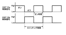
図3は、IGBT23a、23bに制御部45から入力される制御信号の一例を示す図である。この制御信号は、例えば、IGBT23a、23bをオンとすることを示す値とIGBT23a、23bをオとすることを示す値とのいずれかの値を示す信号である。図3の例では、制御信号の信号値がHighである場合にオンを示し、制御信号の信号値がLowである場合にオフを示す例を示しているが、制御信号の値とIGBT23a、23bのオン/オフとの関係はこの例に限定されない。IGBT23a、23bはスイッチング周期と呼ばれる繰り返し周期でオン/オフする。オン時間、オフ時間はそれぞれスイッチング周期の半分の時間である。図3に示すように、IGBT23aと、IGBT23bとでは、オンするタイミングに180°の位相差を設ける。これにより、IGBT23aおよびIGBT23bは、同時にオンすることはない。 FIG. 3 is a diagram illustrating an example of a control signal input from the control unit 45 to the IGBTs 23a and 23b. The control signal is, for example, a signal indicating IGBT23a, 23b and a value indicating that the ON IGBT23a, one of the values a value which indicates that the 23b to off. In the example of FIG. 3, an example is shown in which ON is shown when the signal value of the control signal is High, and OFF is shown when the signal value of the control signal is Low, but the values of the control signal and the IGBTs 23 a and 23 b The relationship between the on / off state is not limited to this example. The IGBTs 23a and 23b are turned on / off in a repetition cycle called a switching cycle. The on-time and off-time are each half the switching period. As shown in FIG. 3, the IGBT 23a and the IGBT 23b provide a 180 ° phase difference at the turn-on timing. Thereby, IGBT23a and IGBT23b do not turn ON simultaneously.

スイッチング周期を短くすると、スイッチング周期の逆数であるスイッチング周波数が高くなり、第一の加熱部11のインピーダンスが大きくなるため、駆動回路51が供給する高周波電流が小さくなり、出力電力が抑制される。反対に、スイッチング周期を長くすると、スイッチング周波数が低くなり、第一の加熱部11のインピーダンスが小さくなるため、駆動回路51が供給する高周波電流が大きくなり、出力電力が上昇する。上記の制御方法は、スイッチング周波数の高さによって出力電力を制御するため、スイッチング周波数制御またはパルス周波数制御と呼ばれている。なお、IGBT23aおよびIGBT23bが同時にオンすると、インバータ回路23が短絡するため、実際の回路ではIGBT23a、23bがともにオフするデッドタイムと呼ばわれる期間を設ける。このため、オン時間はスイッチング周期の半分の時間より短く、オフ時間はスイッチング周期の半分の時間より長くなる。 When the switching cycle is shortened, the switching frequency that is the reciprocal of the switching cycle is increased, and the impedance of the first heating unit 11 is increased. Therefore, the high-frequency current supplied by the drive circuit 51 is decreased, and the output power is suppressed. On the other hand, if the switching cycle is lengthened, the switching frequency is lowered and the impedance of the first heating unit 11 is reduced, so that the high-frequency current supplied by the drive circuit 51 is increased and the output power is increased. The above control method is called switching frequency control or pulse frequency control because the output power is controlled by the height of the switching frequency. Note that when the IGBT 23a and the IGBT 23b are simultaneously turned on, the inverter circuit 23 is short-circuited. Therefore, in an actual circuit, a period called a dead time in which both the IGBTs 23a and 23b are turned off is provided. For this reason, the on-time is shorter than half the switching period, and the off-time is longer than half the switching period.

図4は、IGBT23a、23bのオン/オフを制御する制御信号の別の一例を示す図である。図3の例と同様に、制御信号は、IGBT23a、23bをオンとすることを示す値とIGBT23a、23bをオフとすることを示す値とのいずれかの値を示す信号である。IGBT23a、23bは、図3の例と同様に、スイッチング周期と呼ばれる繰り返し周期でオン/オフする。また、図3の例と同様に、IGBT23aと、IGBT23bとでは、オンするタイミングに180°の位相差を設ける。このため、IGBT23aおよびIGBT23bは、同時にオンすることはない。   FIG. 4 is a diagram showing another example of control signals for controlling on / off of the IGBTs 23a and 23b. Similar to the example of FIG. 3, the control signal is a signal indicating one of a value indicating that the IGBTs 23 a and 23 b are turned on and a value indicating that the IGBTs 23 a and 23 b are turned off. The IGBTs 23a and 23b are turned on / off at a repetition cycle called a switching cycle, as in the example of FIG. Similarly to the example of FIG. 3, the IGBT 23a and the IGBT 23b provide a 180 ° phase difference at the turn-on timing. For this reason, the IGBT 23a and the IGBT 23b are not turned on at the same time.

図4の例では、図3の例と異なり、オン時間はスイッチング周期の半分よりも短い時間である。IGBT23a、23bが両方ともオフしている時、インバータ回路23は電力を出力しない。このため、オン時間を短くすると、駆動回路51が、第一の加熱部11に供給する高周波電流が小さくなり、出力電力が抑制される。オン時間のスイッチング周期に対する比をデューティー比と呼び、上記の制御方法は、デューティー比によって出力電力を制御するため、デューティー比制御と呼ばれている。図4の例では、図3の例に比べデューティー比が小さいため、図3の例に比べ駆動回路51からの出力電力が小さくなる。   In the example of FIG. 4, unlike the example of FIG. 3, the on-time is a time shorter than half of the switching period. When both the IGBTs 23a and 23b are off, the inverter circuit 23 does not output power. For this reason, if ON time is shortened, the high frequency current which the drive circuit 51 supplies to the 1st heating part 11 will become small, and output electric power will be suppressed. The ratio of the on-time to the switching period is called a duty ratio, and the above control method is called duty ratio control because the output power is controlled by the duty ratio. In the example of FIG. 4, since the duty ratio is smaller than that of the example of FIG. 3, the output power from the drive circuit 51 is smaller than that of the example of FIG.

図5は、実施の形態1にかかる誘導加熱調理器100の別の駆動回路51の例を示す図である。図5では、図2と同様の構成要素は、図2と同一の符号を付している。図5に示す構成例では、図2に示した駆動回路51に対して、スイッチング素子としてのIGBT23e、23fと、フライホイールダイオードとしてダイオード23g、23hとを追加した構成である。図5に示したインバータ回路23は、図2に示したインバータ回路23にIGBT23e、23fとダイオード23g、23hとを追加した構成を有し、いわゆるフルブリッジ型のインバータである。図5に示したインバータ回路23は図2に示したインバータ回路23と同様に、直流電源回路22から出力される直流電力を20kHz〜80kHz程度の高周波の交流電力に変換して、第一の加熱部11と共振コンデンサ24からなる共振回路に供給する。   FIG. 5 is a diagram illustrating an example of another drive circuit 51 of the induction heating cooker 100 according to the first embodiment. In FIG. 5, the same components as those in FIG. 2 are denoted by the same reference numerals as those in FIG. In the configuration example shown in FIG. 5, IGBTs 23e and 23f as switching elements and diodes 23g and 23h as flywheel diodes are added to the drive circuit 51 shown in FIG. The inverter circuit 23 shown in FIG. 5 has a configuration in which IGBTs 23e and 23f and diodes 23g and 23h are added to the inverter circuit 23 shown in FIG. 2, and is a so-called full bridge type inverter. As in the inverter circuit 23 shown in FIG. 2, the inverter circuit 23 shown in FIG. 5 converts the DC power output from the DC power supply circuit 22 into high-frequency AC power of about 20 kHz to 80 kHz, and the first heating is performed. This is supplied to a resonance circuit composed of the unit 11 and the resonance capacitor 24.

図6は、図5に示したIGBT23a、23b、23e、23fのオン/オフを制御する制御信号の例を示す図である。IGBT23a、23b、23e、23fはスイッチング周期と呼ばれる繰り返し周期でオン/オフする。オン時間、オフ時間はそれぞれスイッチング周期の半分の時間である。IGBT23aと、IGBT23bとでは、オンするタイミングに180°の位相差を設ける。これにより、IGBT23aおよびIGBT23bは、同時にオンすることはない。IGBT23eと、IGBT23fとでは、オンするタイミングに180°の位相差を設ける。これにより、IGBT23eおよびIGBT23fは、同時にオンすることはない。   FIG. 6 is a diagram illustrating an example of a control signal for controlling on / off of the IGBTs 23a, 23b, 23e, and 23f illustrated in FIG. The IGBTs 23a, 23b, 23e, and 23f are turned on / off at a repetition cycle called a switching cycle. The on-time and off-time are each half the switching period. The IGBT 23a and the IGBT 23b provide a 180 ° phase difference at the turn-on timing. Thereby, IGBT23a and IGBT23b do not turn ON simultaneously. The IGBT 23e and the IGBT 23f provide a 180 ° phase difference at the turn-on timing. Thereby, IGBT23e and IGBT23f are not turned ON simultaneously.

IGBT23aおよびIGBT23f、もしくはIGBT23bおよびIGBT23eがともにオンしている期間において、インバータ回路23が電力を供給する。IGBT23aがオンするタイミングと、IGBT23eがオンするタイミングとに位相差を設けることで、IGBT23aおよびIGBT23f、もしくはIGBT23bおよびIGBT23eがともにオンする期間を設け、インバータ回路23が供給する電力を制御する。上記の制御方法は、位相差によって出力電力を制御するため、位相制御と呼ばれている。なお、IGBT23aおよびIGBT23b、もしくはIGBT23eおよびIGBT23fが同時にオンすると、インバータ回路23が短絡する。このため、実際の回路では、IGBT23aおよびIGBT23bがともにオフする期間と、IGBT23eおよびIGBT23fがともにオフする期間とを設ける。このため、オン時間はスイッチング周期の半分の時間より短く、オフ時間はスイッチング周期の半分の時間より長くなる。   Inverter circuit 23 supplies power in a period in which both IGBT 23a and IGBT 23f, or IGBT 23b and IGBT 23e are on. By providing a phase difference between the timing at which the IGBT 23a is turned on and the timing at which the IGBT 23e is turned on, a period during which both the IGBT 23a and the IGBT 23f or the IGBT 23b and the IGBT 23e are turned on is provided, and the power supplied by the inverter circuit 23 is controlled. The above control method is called phase control because the output power is controlled by the phase difference. When IGBT 23a and IGBT 23b, or IGBT 23e and IGBT 23f are simultaneously turned on, inverter circuit 23 is short-circuited. For this reason, in an actual circuit, a period in which both IGBT 23a and IGBT 23b are turned off and a period in which both IGBT 23e and IGBT 23f are turned off are provided. For this reason, the on-time is shorter than half the switching period, and the off-time is longer than half the switching period.

なお、実施の形態1に係る誘導加熱調理器100の駆動回路51の構成は、図2、図5に示す例に限るものではなく、例えば、一石電圧共振回路などの回路方式により構成する事もできる。一石電圧共振回路は図2のインバータ回路23と同様に、直流電源回路22から出力される直流電力を20kHz〜80kHz程度の高周波の交流電力に変換して、第一の加熱部11と共振コンデンサ24からなる共振回路に供給する。   In addition, the structure of the drive circuit 51 of the induction heating cooking appliance 100 which concerns on Embodiment 1 is not restricted to the example shown in FIG. 2, FIG. 5, For example, you may comprise by circuit systems, such as a one-stone voltage resonance circuit. it can. Similar to the inverter circuit 23 of FIG. 2, the monolithic voltage resonance circuit converts the DC power output from the DC power supply circuit 22 into a high-frequency AC power of about 20 kHz to 80 kHz, and the first heating unit 11 and the resonance capacitor 24. To a resonant circuit consisting of

制御部45は、入力電流検出部25a、出力電流検出部25b、操作部40a、通信部6から与えられた信号に応じて、駆動部50が第一の加熱部11、第二の加熱部12、第三の加熱部13に供給する高周波電力を制御するための制御信号を送信する。   The control unit 45 is configured so that the drive unit 50 has the first heating unit 11 and the second heating unit 12 in accordance with signals given from the input current detection unit 25a, the output current detection unit 25b, the operation unit 40a, and the communication unit 6. The control signal for controlling the high frequency electric power supplied to the 3rd heating part 13 is transmitted.

また、制御部45は、誘導加熱調理器100の動作状態、操作部40、および外部機器200からの入力情報、制御内容等を報知する制御信号を通信部6に送信する。   In addition, the control unit 45 transmits a control signal for notifying the operation state of the induction heating cooker 100, input information from the operation unit 40 and the external device 200, control contents, and the like to the communication unit 6.

通信部6は、外部機器200と無線通信を行うための無線通信手段であり、無線信号を送受信することができる。具体的には、制御部45から受信した制御信号に対して外部機器200との間の通信方式に応じた送信処理を施し、無線信号として外部機器200に送信することができる。または、外部機器200から無線信号として送信された制御信号を受信して、無線信号から制御信号を抽出して制御部45に送信することができる。または、上述した無線信号の送信動作と無線信号の受信動作との両方の動作を行うことができる。通信部6は、誘導加熱調理器100の動作状態を示す情報、誘導加熱調理器100に対する設定情報、および外部機器200から受信した制御信号に基づく情報のうち少なくとも1つを外部機器200へ送信する。   The communication unit 6 is a wireless communication unit for performing wireless communication with the external device 200 and can transmit and receive wireless signals. Specifically, the control signal received from the control unit 45 can be subjected to transmission processing according to the communication method with the external device 200 and transmitted to the external device 200 as a radio signal. Alternatively, a control signal transmitted as a radio signal from the external device 200 can be received, and the control signal can be extracted from the radio signal and transmitted to the control unit 45. Alternatively, both the above-described wireless signal transmission operation and wireless signal reception operation can be performed. The communication unit 6 transmits to the external device 200 at least one of information indicating the operation state of the induction heating cooker 100, setting information for the induction heating cooker 100, and information based on a control signal received from the external device 200. .

通信部6は、制御部45と配線により接続されているが、配線が長いほどノイズの影響を受けやすいため、通信部6と制御部45は近くに配置し、通信部6と制御部45を接続する配線を短くすることが望ましい。   The communication unit 6 is connected to the control unit 45 by wiring. However, the longer the wiring, the more susceptible to noise, so the communication unit 6 and the control unit 45 are arranged close to each other, and the communication unit 6 and the control unit 45 are connected. It is desirable to shorten the wiring to be connected.

通信部6は、内部に無線信号を送信または受信、または送受信するアンテナ部を有しており、より無線信号を送受信しやすくするため、通信部6のアンテナ部が天板4の直下となるように配置することが望ましい。   The communication unit 6 includes an antenna unit that transmits, receives, or transmits / receives a radio signal therein, and the antenna unit of the communication unit 6 is directly below the top plate 4 in order to facilitate transmission / reception of the radio signal. It is desirable to arrange in.

なお、制御部45は、処理回路により実現されるが、この処理回路は、専用のハードウェアであっても、メモリとメモリに格納されるプログラムを実行するCPU(Central Processing Unit、中央処理装置、処理装置、演算装置、マイクロプロセッサ、マイクロコンピュータ、プロセッサ、DSP(Digital Signal Processor)ともいう)とを備える制御回路であってもよい。ここで、メモリとは、例えば、RAM(Random Access Memory)、ROM(Read Only Memory)、フラッシュメモリー、EPROM(Erasable Programmable Read Only Memory)、EEPROM(Electrically Erasable Programmable Read Only Memory)等の、不揮発性または揮発性の半導体メモリ、磁気ディスク、フレキシブルディスク、光ディスク、コンパクトディスク、ミニディスク、DVD(Digital Versatile Disk)等が該当する。   Note that the control unit 45 is realized by a processing circuit. Even if the processing circuit is dedicated hardware, the CPU (Central Processing Unit, a central processing unit, a CPU that executes a program stored in the memory and the memory, A control circuit including a processing device, an arithmetic device, a microprocessor, a microcomputer, a processor, and a DSP (Digital Signal Processor) may be used. Here, the memory is, for example, a RAM (Random Access Memory), a ROM (Read Only Memory), a flash memory, an EPROM (Erasable Programmable Read Only Memory, or an EEPROM (Electrically Erasable Memory). A volatile semiconductor memory, a magnetic disk, a flexible disk, an optical disk, a compact disk, a mini disk, a DVD (Digital Versatile Disk), and the like are applicable.

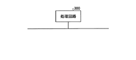
制御部45が、専用のハードウェアで実現される場合、これらは、図7に示す処理回路300により実現される。処理回路300は、例えば、単一回路、複合回路、プログラム化したプロセッサ、並列プログラム化したプロセッサ、ASIC(Application Specific Integrated Circuit)、FPGA(Field Programmable Gate Array)、またはこれらを組み合わせたものである。   When the control unit 45 is realized by dedicated hardware, these are realized by the processing circuit 300 shown in FIG. The processing circuit 300 is, for example, a single circuit, a composite circuit, a programmed processor, a parallel programmed processor, an ASIC (Application Specific Integrated Circuit), an FPGA (Field Programmable Gate Array), or a combination thereof.

制御部45がCPUを備える制御回路で実現される場合、この制御回路は例えば図8に示す構成の制御回路400である。図8に示すように制御回路400は、CPUであるプロセッサ401と、メモリ402とを備える。制御部45が制御回路400により実現される場合、プロセッサ401がメモリ402に記憶された、制御部45の処理に対応するプログラムを読み出して実行することにより実現される。また、メモリ402は、プロセッサ401が実施する各処理における一時メモリとしても使用される。   When the control unit 45 is realized by a control circuit including a CPU, the control circuit is, for example, a control circuit 400 having a configuration shown in FIG. As shown in FIG. 8, the control circuit 400 includes a processor 401 that is a CPU and a memory 402. When the control unit 45 is realized by the control circuit 400, it is realized by the processor 401 reading and executing a program stored in the memory 402 and corresponding to the process of the control unit 45. The memory 402 is also used as a temporary memory in each process executed by the processor 401.

外部機器200は、スマートフォン等の無線通信が可能な機器であって、無線通信により、誘導加熱調理器100が被加熱物を加熱する際の投入火力、調理メニューを設定するための制御信号を送信する機能を持つ。   The external device 200 is a device capable of wireless communication such as a smartphone, and transmits a control signal for setting an input heating power and a cooking menu when the induction heating cooker 100 heats an object to be heated by wireless communication. It has a function to do.

図9は、外部機器200の構成例を示す図である。図9に示すように、外部機器200は、通信部201、制御部202、表示部203および操作部204を備える。通信部201は、無線通信を行う。制御部202は、外部機器200の動作全体を制御する。表示部203は、制御部202からの指示に従って、外部機器200の操作者に報知するための画像および文字などを表示する。表示部203は、例えば液晶モニタで構成される。操作部204は、外部機器200の操作者からの入力を受け付ける入力装置すなわち受信部である。操作部204は、例えば、タッチパネル、ボタン、スイッチである。表示部203と操作部204は一体に構成されていてもよい。   FIG. 9 is a diagram illustrating a configuration example of the external device 200. As illustrated in FIG. 9, the external device 200 includes a communication unit 201, a control unit 202, a display unit 203, and an operation unit 204. The communication unit 201 performs wireless communication. The control unit 202 controls the overall operation of the external device 200. The display unit 203 displays an image, characters, and the like for notifying the operator of the external device 200 in accordance with an instruction from the control unit 202. The display unit 203 is composed of a liquid crystal monitor, for example. The operation unit 204 is an input device that receives an input from an operator of the external device 200, that is, a reception unit. The operation unit 204 is, for example, a touch panel, a button, or a switch. The display unit 203 and the operation unit 204 may be configured integrally.

制御部202は、操作者から誘導加熱調理器100を操作することを受け付ける場合、誘導加熱調理器100を操作するための入力情報を受け付ける画面を表示するよう表示部203へ指示する。表示部203は、制御部202からの指示に従って、誘導加熱調理器100を操作するための入力情報を受け付ける画面を表示する。操作者は、表示された画面に基づいて、操作部204を操作することにより入力情報を入力する。例えば、表示部203は、湯沸かしモード、揚げ物モードなど調理メニューを示す画像を表示し、操作者が、表示されたモードのうちの1つを操作部204により選択する。操作部204は、操作者により選択されたモードを制御部202へ通知し、制御部202は、操作部204から通知されたモードを示す制御信号を生成して、通信部201へ出力する。通信部201は、入力された制御信号を無線信号として誘導加熱調理器100へ送信する。   When the control unit 202 receives an operation of the induction heating cooker 100 from the operator, the control unit 202 instructs the display unit 203 to display a screen for receiving input information for operating the induction heating cooker 100. Display unit 203 displays a screen that accepts input information for operating induction heating cooker 100 in accordance with an instruction from control unit 202. The operator inputs input information by operating the operation unit 204 based on the displayed screen. For example, the display unit 203 displays an image indicating a cooking menu such as a kettle mode or a fried food mode, and the operator selects one of the displayed modes using the operation unit 204. The operation unit 204 notifies the control unit 202 of the mode selected by the operator, and the control unit 202 generates a control signal indicating the mode notified from the operation unit 204 and outputs the control signal to the communication unit 201. The communication unit 201 transmits the input control signal to the induction heating cooker 100 as a radio signal.

投入火力の入力を操作者から受け付ける場合にも、外部機器200では、同様に、表示部203に操作を受け付けるための画面を表示し、操作部204により投入火力を示す情報の入力を受け付ける。制御部202は、入力された投入火力を示す制御信号を生成して、通信部201へ出力する。通信部201は、入力された制御信号を無線信号として誘導加熱調理器100へ送信する。外部機器200では、誘導加熱調理器100の加熱開始および加熱停止についても、同様に、操作部204により操作者からの入力を受け付ける。   Even when the input of the input thermal power is received from the operator, the external device 200 similarly displays a screen for receiving the operation on the display unit 203 and receives the input of information indicating the input thermal power through the operation unit 204. The control unit 202 generates a control signal indicating the input heating power and outputs it to the communication unit 201. The communication unit 201 transmits the input control signal to the induction heating cooker 100 as a radio signal. In the external device 200, the input from the operator is similarly received by the operation unit 204 for the heating start and the heating stop of the induction heating cooker 100.

また、通信部201は、誘導加熱調理器100から送信された無線信号を受信すると、受信した信号から情報を抽出し、抽出した情報を制御部202へ入力する。制御部202は、入力された情報を表示するよう表示部203へ指示し、表示部203は、制御部202からの指示に基づいて、情報を表示する。誘導加熱調理器100から送信された無線信号に含まれる情報は、例えば、誘導加熱調理器100の動作状態を示す情報である。   In addition, when the communication unit 201 receives the wireless signal transmitted from the induction heating cooker 100, the communication unit 201 extracts information from the received signal and inputs the extracted information to the control unit 202. The control unit 202 instructs the display unit 203 to display the input information, and the display unit 203 displays information based on the instruction from the control unit 202. The information included in the wireless signal transmitted from the induction heating cooker 100 is information indicating the operating state of the induction heating cooker 100, for example.

制御部202は処理回路により実現され、この処理回路は、専用のハードウェアであってもよいし、CPUを備えた制御回路であってもよい。制御部202が専用のハードウェアにより実現される場合、この処理回路は例えば、図7に示した処理回路300である。制御部202がCPUを備えた制御回路により実現される場合、この制御回路は、例えば、図8に示した制御回路400である。   The control unit 202 is realized by a processing circuit, and this processing circuit may be dedicated hardware or a control circuit including a CPU. When the control unit 202 is realized by dedicated hardware, this processing circuit is, for example, the processing circuit 300 shown in FIG. When the control unit 202 is realized by a control circuit including a CPU, the control circuit is, for example, the control circuit 400 illustrated in FIG.

以上の説明では、外部機器200が、誘導加熱調理器100から送信された無線信号の受信と誘導加熱調理器100への無線信号の送信との両方を行う例を説明したが、いずれか一方を行ってもよい。   In the above description, the example in which the external device 200 performs both reception of a wireless signal transmitted from the induction heating cooker 100 and transmission of a wireless signal to the induction heating cooker 100 has been described. You may go.

次に実施の形態1にかかる誘導加熱調理器100の動作を説明する。図10は、実施の形態1にかかる誘導加熱調理器100の制御部45の構成例を示す図である。図10では、誘導加熱調理器100のうち第一の加熱部11と第一の加熱部11の制御にかかる構成要素を図示し、第二の加熱部12および第三の加熱部13と、これらの制御にかかる構成要素の図示を省略している。   Next, operation | movement of the induction heating cooking appliance 100 concerning Embodiment 1 is demonstrated. FIG. 10 is a diagram illustrating a configuration example of the control unit 45 of the induction heating cooker 100 according to the first embodiment. In FIG. 10, the component concerning the control of the 1st heating part 11 and the 1st heating part 11 among the induction heating cooking appliances 100 is illustrated, the 2nd heating part 12 and the 3rd heating part 13, and these The components related to the control are omitted from illustration.

図10に示すように、制御部45は、演算部451、通信周期検出部452および駆動制御部453を備える。演算部451は、操作部40aから入力される入力情報に基づいて加熱部11〜13ごとの目標電力を算出し、目標電力を駆動制御部453へ指示する。目標電力は、操作部40aまたは外部機器200から入力された調理メニューまたは投入火力などに応じて算出される指令値、または後述するように無線信号への干渉を考慮して指令値から変更された値である。駆動制御部453は、目標電力と、入力電流検出部25aによる電流の検出値と、出力電流検出部25bによる電流の検出値とに基づいて、駆動回路51のインバータ回路23の各スイッチング素子のオン/オフを制御するための制御信号を生成し、インバータ回路23へ入力する。   As illustrated in FIG. 10, the control unit 45 includes a calculation unit 451, a communication cycle detection unit 452, and a drive control unit 453. The calculating part 451 calculates the target electric power for every heating parts 11-13 based on the input information input from the operation part 40a, and instruct | indicates target electric power to the drive control part 453. FIG. The target power is changed from the command value calculated in accordance with the cooking menu or the input heating power input from the operation unit 40a or the external device 200, or considering the interference with the radio signal as will be described later. Value. The drive control unit 453 turns on each switching element of the inverter circuit 23 of the drive circuit 51 based on the target power, the detected current value by the input current detecting unit 25a, and the detected current value by the output current detecting unit 25b. A control signal for controlling / off is generated and input to the inverter circuit 23.

演算部451は、操作部40aから投入火力を示す入力情報が入力された場合は、投入火力が電力により指示されている場合、該投入火力を目標電力に設定する。投入火力が電力により指示されていない場合、例えば、強、中、弱などにより指示されている場合、入力情報を電力に変換して、変換により得られた値を目標電力に設定する。また、投入火力が調理メニューにより指示されている場合、演算部451は、あらかじめ定められた調理メニューごとの投入電力の動作情報に従って、加熱部11〜13ごとの目標電力を算出する。投入電力の動作情報とは、例えば、第一の加熱口1、第二の加熱口2、第三の加熱口3の温度を検出する図示しない温度センサを用いて、第一の加熱口1、第二の加熱口2、第三の加熱口3の温度が第1の温度となるまでは投入電力を第1の値に設定し、第一の加熱口1、第二の加熱口2、第三の加熱口3の温度が第1の温度になった後は、投入電力を第2の値に設定するなどの動作を示す情報である。 When the input information indicating the input thermal power is input from the operation unit 40a, the calculation unit 451 sets the input thermal power as the target power when the input thermal power is instructed by the power. When the input heating power is not instructed by power, for example, instructed by strong, medium, weak, etc., the input information is converted into power, and the value obtained by the conversion is set as the target power. When the input heating power is instructed by the cooking menu, the calculation unit 451 calculates the target power for each of the heating units 11 to 13 according to the operation information of the input power for each predetermined cooking menu. The operation information of the input power is, for example, a first heating port 1, a temperature sensor (not shown) that detects the temperature of the first heating port 1, the second heating port 2, and the third heating port 3. The input power is set to the first value until the temperature of the second heating port 2 and the third heating port 3 reaches the first temperature, and the first heating port 1, the second heating port 2, After the temperature of the third heating port 3 reaches the first temperature, the information indicates an operation such as setting the input power to the second value.

通信周期検出部452は、通信部6が実行する無線通信に周期性が有るか否かを判定し、無線通信に周期性が有る場合、周期を算出する。   The communication cycle detection unit 452 determines whether or not the wireless communication executed by the communication unit 6 has periodicity, and calculates the cycle when the wireless communication has periodicity.

本実施の形態では、制御部45が、通信部6と外部機器200が無線通信を行う期間において、駆動部50が供給する高周波電力を変更する制御、すなわち電力変更制御を行う。以下、電力変更制御について説明する。   In the present embodiment, the control unit 45 performs control for changing high-frequency power supplied by the driving unit 50, that is, power change control, during a period in which the communication unit 6 and the external device 200 perform wireless communication. Hereinafter, the power change control will be described.

図11は、駆動回路51が第一の加熱部11へ供給する高周波電力と、通信部6が無線通信を行う期間との関係の一例を示す図である。以下、第一の加熱部11を例に説明するが、第二の加熱部12、第三の加熱部13においても、同様の制御を行ってもよい。図11では、上段に第一の加熱部11に入力される電流を示し、下段に無線通信の状態を示している。また、図11の上段の点線は、本来の指令値に対応する電流の振幅である出力指令値振幅を示している。図11に示した例では、制御部45の演算部451は、通信部6が無線通信を実行する期間すなわち第1の期間において、駆動回路51が供給する高周波電力を停止させる。具体的には、例えば、演算部451は、駆動制御部453に本来の指令値とは異なる制御目標値である目標電力として0を出力する。これにより、第一の加熱部11で発生する漏洩磁束を少なくし、無線信号への漏洩磁束による干渉を抑制する。 FIG. 11 is a diagram illustrating an example of the relationship between the high-frequency power supplied from the drive circuit 51 to the first heating unit 11 and the period during which the communication unit 6 performs wireless communication. Hereinafter, although the 1st heating part 11 is demonstrated to an example, you may perform the same control also in the 2nd heating part 12 and the 3rd heating part 13. FIG. In FIG. 11, the current input to the first heating unit 11 is shown in the upper stage, and the state of wireless communication is shown in the lower stage. Further, the upper dotted line in FIG. 11 indicates the output command value amplitude which is the amplitude of the current corresponding to the original command value. In the example illustrated in FIG. 11, the calculation unit 451 of the control unit 45 stops the high-frequency power supplied by the drive circuit 51 during the period in which the communication unit 6 performs wireless communication, that is, the first period. Specifically, for example, the calculation unit 451 outputs 0 to the drive control unit 453 as a target power that is a control target value different from the original command value. Thereby, the leakage magnetic flux which generate | occur | produces in the 1st heating part 11 is decreased, and the interference by the leakage magnetic flux to a radio signal is suppressed.

図12は、駆動回路51が第一の加熱部11へ供給する高周波電力と、通信部6が無線通信を行う期間との関係の別の一例を示す図である。図12では、上段に第一の加熱部11に入力される電流を示し、下段に無線通信の状態を示している。また、図12の上段の点線は、本来の指令値に対応する電流の振幅である出力指令値振幅を示している。図12に示した例では、通信部6が無線通信を実行する期間すなわち第1の期間において、駆動回路51が供給する高周波電力を抑制する。すなわち図12に示した例では、通信部6が無線通信を実行する期間すなわち第1の期間では、駆動回路51が供給する高周波電力は、無線通信を実行していない期間すなわち第2の期間に比べて小さい。   FIG. 12 is a diagram illustrating another example of the relationship between the high-frequency power supplied from the drive circuit 51 to the first heating unit 11 and the period during which the communication unit 6 performs wireless communication. In FIG. 12, the current input to the first heating unit 11 is shown in the upper stage, and the state of wireless communication is shown in the lower stage. Also, the upper dotted line in FIG. 12 indicates the output command value amplitude which is the amplitude of the current corresponding to the original command value. In the example illustrated in FIG. 12, high-frequency power supplied by the drive circuit 51 is suppressed in a period during which the communication unit 6 performs wireless communication, that is, a first period. That is, in the example shown in FIG. 12, in the period in which the communication unit 6 executes wireless communication, that is, in the first period, the high-frequency power supplied by the drive circuit 51 is in the period in which wireless communication is not executed, that is, in the second period. Smaller than that.

具体的には、例えば、演算部451は、駆動制御部453に対して、本来の指令値の替わりに指示値として無線通信を実行していない期間に比べて小さい電力を指定する。これにより、第一の加熱部11で発生する漏洩磁束を少なくし、無線信号への漏洩磁束による干渉を抑制し、かつ、図11に示したように供給する高周波電力を停止する場合と比べて、より本来の指令値に近い出力電力を得ることができる。本来の指令値とは、漏洩磁束を少なくするために出力電力を抑制する前の指令値であり、例えば、操作部40または外部機器200により設定された情報に基づく指令値である。   Specifically, for example, the calculation unit 451 designates a small power to the drive control unit 453 as compared to a period during which wireless communication is not performed as an instruction value instead of the original command value. Thereby, the leakage magnetic flux generated in the first heating unit 11 is reduced, the interference due to the leakage magnetic flux to the radio signal is suppressed, and the high-frequency power supplied as shown in FIG. 11 is stopped. Thus, output power closer to the original command value can be obtained. The original command value is a command value before suppressing the output power in order to reduce the leakage magnetic flux, for example, a command value based on information set by the operation unit 40 or the external device 200.

通信周期検出部452は、通信部6から出力される通信開始および終了を示す信号に基づいて、通信部6と外部機器200が無線通信に周期性が有るか否かを判断する。なお、通信部6は、外部機器200と無線接続すると、外部機器200との間の通信の開始および終了時に通信周期検出部452へそれぞれ通信開始および終了を示す信号を出力する。通信周期検出部452は、通信開始および終了を示す信号に基づいて、例えば、通信開始および終了の時刻を記憶し、過去の通信開始の時刻から、通信開始の時刻間の時間差Δt1を算出する。通信周期検出部452は、複数のΔt1を算出し、複数のΔt1を統計処理して、標準偏差または分散があらかじめ定められたしきい値以下である場合に、周期性が有ると判定する。周期性の有無の判定方法はこの例に限定されない。The communication cycle detection unit 452 determines whether or not the wireless communication between the communication unit 6 and the external device 200 has periodicity based on signals indicating the start and end of communication output from the communication unit 6. When wirelessly connected to the external device 200, the communication unit 6 outputs a signal indicating the start and end of communication to the communication cycle detection unit 452 at the start and end of communication with the external device 200, respectively. The communication cycle detection unit 452 stores, for example, communication start and end times based on signals indicating communication start and end, and calculates a time difference Δt 1 between the communication start times from the past communication start times. . Communication cycle detector 452 determines that calculates a plurality of Delta] t 1, and statistically processes the plurality of Delta] t 1, when the standard deviation or variance is below the threshold a predetermined periodicity there . The method for determining the presence or absence of periodicity is not limited to this example.

通信周期検出部452は、通信部6と外部機器200が無線通信に周期性が有ると判断した場合、複数のΔt1に基づいて通信部6と外部機器200の間の無線通信の周期を算出する。また、通信開始の時刻から終了までの時間を算出し、算出した値に基づいて、周期内での、通信の継続時間すなわち無線通信を実行する期間を算出する。周期内において、無線通信を実行する期間を除いた期間を、無線通信を実行しない期間、または無線通信の休止期間と呼ぶ。以上の処理により、通信周期検出部452は、無線通信を実行する期間と無線通信の休止期間とを把握することができる。通信周期検出部452は、無線通信を実行する期間と無線通信の休止期間との開始時刻を予測し、演算部451へ通知する。When it is determined that the communication unit 6 and the external device 200 have periodicity in wireless communication, the communication cycle detection unit 452 calculates the cycle of wireless communication between the communication unit 6 and the external device 200 based on a plurality of Δt 1. To do. Also, the time from the communication start time to the end is calculated, and based on the calculated value, the communication continuation time, that is, the period during which wireless communication is executed within the cycle is calculated. Within the cycle, a period excluding a period for performing wireless communication is referred to as a period for not performing wireless communication, or a wireless communication suspension period. Through the above processing, the communication cycle detection unit 452 can grasp the period during which wireless communication is executed and the suspension period of wireless communication. The communication cycle detection unit 452 predicts the start time of the period during which wireless communication is executed and the wireless communication suspension period, and notifies the calculation unit 451 of the start time.

演算部451は、予測した無線通信を実行する期間が通知されると、通知された無線通信を実行する期間の開始とともに、または通知された無線通信を実行する期間の開始の直前に、上述したように、駆動制御部453に出力する目標電力を変更する制御を行う。無線通信の実行を検出してから、駆動制御部453に出力する指示値を変更すると、無線通信の開始から目標電力が変更されるまでの間、第一の加熱部11で発生する漏洩磁束が無線信号に干渉する可能性が有る。本実施の形態では、無線通信の周期を求め、無線通信を実行する期間を予測して上記の制御を行うことで、無線通信を実行する期間において、はじめから第一の加熱部11で発生する漏洩磁束を抑制することができるため、通信品質を向上させることができる。   When the calculation unit 451 is notified of the period for executing the predicted wireless communication, the calculation unit 451 is described above with the start of the period for executing the notified wireless communication or immediately before the start of the period for executing the notified wireless communication. As described above, control for changing the target power output to the drive control unit 453 is performed. When the instruction value output to the drive control unit 453 is changed after the execution of the wireless communication is detected, the leakage magnetic flux generated in the first heating unit 11 from the start of the wireless communication until the target power is changed. There is a possibility of interference with radio signals. In the present embodiment, the first heating unit 11 generates the period of the wireless communication from the beginning in the period of executing the wireless communication by obtaining the period of the wireless communication, predicting the period of executing the wireless communication and performing the above control. Since leakage magnetic flux can be suppressed, communication quality can be improved.

なお、通信周期検出部452は、通信部6と外部機器200が無線通信に周期性が無いと判断した場合には、演算部451にその旨を通知し、無線通信の開始および終了を検出するたびに、演算部451に、無線通信の開始および終了を通知する。演算部451は、無線通信の開始が通知されると、駆動制御部453に出力する目標電力を変更し、無線通信の終了が通知されると駆動制御部453に出力する目標電力を本来の指令値、すなわち変更する前の目標電力に戻す。   When the communication unit 6 and the external device 200 determine that the wireless communication has no periodicity, the communication cycle detection unit 452 notifies the calculation unit 451 of the fact and detects the start and end of the wireless communication. Each time, the calculation unit 451 is notified of the start and end of wireless communication. The calculation unit 451 changes the target power output to the drive control unit 453 when the start of wireless communication is notified, and the target power output to the drive control unit 453 when the end of wireless communication is notified. Return to the value, that is, the target power before the change.

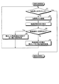
図13は、本実施の形態1の電力変更制御手順の一例を示すフローチャートである。図13は、外部機器200との通信中に加熱動作を実施する場合のフローチャートである。まず、誘導加熱調理器100の制御部45は、操作部40の操作または外部機器200からの制御信号により加熱動作の開始を指示されると、加熱動作を開始し、操作部40の操作または外部機器200からの制御信号により、加熱停止を指示する情報である加熱停止命令が入力されたか否かを判断する(ステップS1)。加熱停止命令が入力された場合(ステップS1 Yes)、制御部45は、加熱動作を終了する。   FIG. 13 is a flowchart illustrating an example of a power change control procedure according to the first embodiment. FIG. 13 is a flowchart when a heating operation is performed during communication with the external device 200. First, when the control unit 45 of the induction heating cooker 100 is instructed to start the heating operation by the operation of the operation unit 40 or the control signal from the external device 200, the control unit 45 starts the heating operation. Based on the control signal from the device 200, it is determined whether or not a heating stop command, which is information for instructing the heating stop, is input (step S1). When a heating stop command is input (step S1 Yes), the control unit 45 ends the heating operation.

加熱停止命令が入力されていない場合(ステップS1 No)、誘導加熱調理器100は、加熱動作を継続する(ステップS2)。具体的には、制御部45は、操作部40の操作または外部機器200からの制御信号に基づいて目標電力を生成して、駆動回路51へ指示し、駆動回路51は第一の加熱部11へ高周波電力を入力する。初期状態では、目標電力は、指令値である。   When the heating stop command has not been input (No at Step S1), the induction heating cooker 100 continues the heating operation (Step S2). Specifically, the control unit 45 generates target power based on the operation of the operation unit 40 or a control signal from the external device 200 and instructs the drive circuit 51, and the drive circuit 51 is in the first heating unit 11. Input high frequency power to. In the initial state, the target power is a command value.

また、加熱動作の継続中に、制御部45は、通信部6と外部機器200が行っている無線通信の周期を検出する(ステップS3)。具体的には、通信周期検出部452が、通信部6と外部機器200が行っている無線通信に周期性が有るか否かの判定を行い、周期性が有ると判定した場合、周期の算出処理と無線通信を実行する期間の予測処理とを実施する。   Further, during the heating operation, the control unit 45 detects the cycle of wireless communication performed by the communication unit 6 and the external device 200 (step S3). Specifically, if the communication cycle detection unit 452 determines whether or not the wireless communication performed by the communication unit 6 and the external device 200 has periodicity, and determines that there is periodicity, the calculation of the cycle is performed. The process and the prediction process of the period for executing the wireless communication are performed.

制御部45は、通信部6と外部機器200が行っている無線通信に周期性が有ると判定した場合(ステップS4 Yes)、無線通信を実行する期間の予測に基づいて、第一の加熱部11へ供給する高周波電力を変更する制御を行い(ステップS5)、ステップS1へ戻る。具体的には、制御部45は、上述したように、無線通信を実行する期間の予測に基づいて、無線通信を実行する期間に第一の加熱部11へ供給する高周波電力を抑制し、無線通信の休止期間では、高周波電力を元に戻す制御を実施する。   When it is determined that the wireless communication performed by the communication unit 6 and the external device 200 has periodicity (Yes in step S4), the control unit 45 determines the first heating unit based on the prediction of the period for performing the wireless communication. 11 is performed to change the high-frequency power supplied to 11 (step S5), and the process returns to step S1. Specifically, as described above, the control unit 45 suppresses the high-frequency power supplied to the first heating unit 11 during the wireless communication period based on the prediction of the period during which the wireless communication is performed, and wirelessly In the communication suspension period, control for restoring the high-frequency power is performed.

制御部45は、通信部6と外部機器200が行っている無線通信に周期性が無いと判定した場合(ステップS4 No)、無線通信の実行を検出してから第一の加熱部11へ供給する高周波電力を変更する制御を行い(ステップS6)、ステップS1へ戻る。上述したように、制御部45は、第二の加熱部12、第三の加熱部13についてもそれぞれ同様の制御を実施してもよい。   When it is determined that the wireless communication performed by the communication unit 6 and the external device 200 has no periodicity (No in step S4), the control unit 45 detects the execution of the wireless communication and then supplies the wireless communication to the first heating unit 11. Control to change the high frequency power to be performed is performed (step S6), and the process returns to step S1. As described above, the control unit 45 may perform the same control for the second heating unit 12 and the third heating unit 13, respectively.

また、制御部45は、外部機器200に対して、無線通信を行う周期を指定する制御信号を生成し、通信部6経由で外部機器200へ送信するようにしてもよい。これによれば、制御部45は、熱または保温といった調理モードまたは加熱状態などに応じて、外部機器200との間の無線通信を行う周期を決定できる。例えば、熱モードで被加熱物5を設定温度まで加熱している場合は、被加熱物5の温度情報を比較的短い周期で無線通信により外部機器200に送信し、温度を知らせる。一方で、熱完了後には、被加熱物5の温度情報を比較的長い周期で、無線通信により外部機器200に送信することが考えられる。これによって、頻繁な通信を必要としない場合には、無線通信の回数をより少なくし、駆動部50が供給する高周波電力を変更する回数を少なくできるため、より本来の指令値に近い電力を得ることができる。 In addition, the control unit 45 may generate a control signal for designating a cycle for performing wireless communication with respect to the external device 200 and transmit the control signal to the external device 200 via the communication unit 6. According to this, the control unit 45, in accordance with the cooking mode or the heating conditions such as preheating or thermal insulation, can determine the period for performing wireless communication with the external apparatus 200. For example, if in preheating mode is heating an object 5 to a set temperature is transmitted to the external apparatus 200 via wireless communication in a relatively short period the temperature information of the object to be heated 5 informs the temperature. On the other hand, after preheat completed, a relatively long period the temperature information of the object to be heated 5, it is conceivable to transmit to the external device 200 by wireless communication. As a result, when frequent communication is not required, the number of times of wireless communication can be reduced, and the number of times of changing the high-frequency power supplied by the drive unit 50 can be reduced, so that power closer to the original command value can be obtained. be able to.

以上の処理により、駆動回路51は、通信部6と外部機器200が無線通信を実行しない期間において、第一の加熱部11に供給する高周波電力を抑制または停止することができる。無線通信を行う時に第一の加熱部11への出力電力を抑制または停止する制御を行う場合、平均出力電力が指令値よりも小さくなるが、無線通信に周期性がある場合、無線通信の休止期間に駆動回路51が供給する高周波電力を本来の指令値に対応する値より上昇させておけば、より本来の指令値に近い平均出力電力を第一の加熱部11に供給することができる。例えば、本来の指令値をXとした場合、無線通信を実行する期間がTaであり、無線通信の休止期間がTbである場合、制御部45は、無線通信を実行する期間の目標電力をX−ΔXとし、無線通信の休止期間の目標電力をX+ΔX×Ta/Tbとする。 With the above processing, the drive circuit 51 can suppress or stop the high-frequency power supplied to the first heating unit 11 during a period in which the communication unit 6 and the external device 200 do not perform wireless communication. When performing control to suppress or stop output power to the first heating unit 11 when performing wireless communication, the average output power is smaller than the command value, but when wireless communication is periodic, the wireless communication is suspended. If the high-frequency power supplied by the drive circuit 51 during the period is increased from the value corresponding to the original command value, the average output power closer to the original command value can be supplied to the first heating unit 11. For example, if the original command value and X, a period T a which executes wireless communication, if rest period wireless communication is T b, the control unit 45, the target power duration for executing the radio communication Is X−ΔX, and the target power of the wireless communication suspension period is X + ΔX × T a / T b .

図14は、無線通信の休止期間で出力電力を上昇させる場合の駆動回路51が供給する高周波電力の一例を示す図である。図14では、上段に第一の加熱部11に入力される電流を示し、下段に無線通信の状態を示している。また、図14の上段の点線は、本来の指令値に対応する電流の振幅である出力指令値振幅を示している。図14の例では、駆動回路51は、無線通信を行う期間においては、本来の指令値よりも小さい高周波電力を出力している。一方で、駆動回路51は、無線通信を行わない期間においては、指令値以上の高周波電力を出力することで、より指令値に近い平均出力電力を第一の加熱部11に供給することができる。なお、図14は駆動回路51が供給する高周波電力をスイッチング周波数制御によって変更した場合を示している。   FIG. 14 is a diagram illustrating an example of the high-frequency power supplied by the drive circuit 51 when the output power is increased in the wireless communication pause period. In FIG. 14, the electric current input into the 1st heating part 11 is shown in the upper stage, and the state of radio | wireless communication is shown in the lower stage. 14 indicates the output command value amplitude, which is the amplitude of the current corresponding to the original command value. In the example of FIG. 14, the drive circuit 51 outputs high-frequency power that is smaller than the original command value during the period of wireless communication. On the other hand, the drive circuit 51 can supply the average output power closer to the command value to the first heating unit 11 by outputting high-frequency power equal to or higher than the command value during a period when wireless communication is not performed. . FIG. 14 shows a case where the high frequency power supplied by the drive circuit 51 is changed by switching frequency control.

また、制御部45は、操作部40a〜40cを介して設定された特定の出力電力において、無線通信が正確に行われないと判断した場合、無線通信の周期性の有無にかかわらず、駆動回路51からの出力電力の抑制および上昇を繰り返し、指令値に近い平均出力電力を得る制御を行う。スイッチング周波数制御では、駆動回路51からの出力電力によって高周波電流の周波数が決まる。このため、出力電力の上昇および抑制を繰り返す制御を行うことで、第一の加熱部11に流れる高周波電流の周波数を変更することができる。これによって、特定周波数の漏洩磁束が無線通信信号に干渉している場合には、干渉を起こさない周波数で動作し、かつ、より指令値に近い平均出力電力を加熱コイルに供給することができる。   In addition, when the control unit 45 determines that the wireless communication is not accurately performed with the specific output power set via the operation units 40a to 40c, the drive circuit regardless of whether the wireless communication has periodicity or not. The control to obtain the average output power close to the command value is performed by repeatedly suppressing and increasing the output power from 51. In the switching frequency control, the frequency of the high frequency current is determined by the output power from the drive circuit 51. For this reason, the frequency of the high frequency current which flows into the 1st heating part 11 can be changed by performing control which repeats a raise and suppression of output electric power. Thereby, when the leakage magnetic flux of a specific frequency interferes with the wireless communication signal, it can operate at a frequency that does not cause interference and supply the average output power closer to the command value to the heating coil.

無線通信が正確に行われていることの判定は、例えば、次の方法により実施する。外部機器200から通信部6に無線信号が送信された場合、通信部6は、受信した制御信号の内容を確認する信号を外部機器200に送信する。そして、外部機器200は受信した信号から、通信部6で正しく制御信号が受信されたか否かに関する信号を、通信部6に再度送信する。これにより、通信部6は、無線通信が正確に行われているか否かを確認することができる。通信部6は、無線通信が正確に行われているか否かを示す情報を制御部45へ通知する。この通知に基づいて制御部45は、無線通信が正確に行われているか否かを判断することができる。もしくは、逆の場合として、通信部6から外部機器200に制御信号が送信された場合、受信した制御信号の内容を確認する信号を外部機器200から通信部6に送信する。そして、通信部6は受信した信号から、外部機器200で正しく制御信号が受信されているか否かを確認する方法がある。あるいは、これら両方の方法を実施してもよい。   The determination that the wireless communication is being performed accurately is performed, for example, by the following method. When a wireless signal is transmitted from the external device 200 to the communication unit 6, the communication unit 6 transmits a signal for confirming the content of the received control signal to the external device 200. Then, the external device 200 transmits again a signal regarding whether or not the control signal is correctly received by the communication unit 6 from the received signal to the communication unit 6. Thereby, the communication part 6 can confirm whether radio | wireless communication is performed correctly. The communication unit 6 notifies the control unit 45 of information indicating whether or not wireless communication is accurately performed. Based on this notification, the control unit 45 can determine whether or not wireless communication is accurately performed. Alternatively, as a reverse case, when a control signal is transmitted from the communication unit 6 to the external device 200, a signal for confirming the content of the received control signal is transmitted from the external device 200 to the communication unit 6. Then, there is a method in which the communication unit 6 confirms whether the control signal is correctly received by the external device 200 from the received signal. Alternatively, both of these methods may be implemented.

また、無線通信が正確に行われていることの判定を行う別の方法として、外部機器200と通信部6間で無線通信する制御信号の形式を予め定めておき、受信した制御信号が正しい形式であるか否かによって判定する方法もある。   As another method for determining that wireless communication is being performed accurately, a control signal format for wireless communication between the external device 200 and the communication unit 6 is determined in advance, and the received control signal is in the correct format. There is also a method of determining by whether or not.

他にも、無線通信が正確に行われていることの判定を行う別の方法は、外部機器200と通信部6間で通信する制御信号の、少なくとも開始と終了箇所に無線通信成功の目印となる符号を付加して、全ての目印を含めて制御信号が受信できたか否かによって判定を行う方法もある。無線通信が正確に行われていることの判定を行う方法は、上記の例に限定されず、どのような方法を用いてもよい。   In addition, another method for determining whether wireless communication is being performed accurately is a control signal for communication between the external device 200 and the communication unit 6, and at least the start and end points of the wireless communication success mark There is also a method of making a determination based on whether or not the control signal has been received including all the marks. The method for determining that wireless communication is accurately performed is not limited to the above example, and any method may be used.

以上のように、本実施の形態の誘導加熱調理器100では、無線通信の周期性の有無を判定し、周期性がある場合、無線通信を実行する期間と無線通信を実行しない期間とを求め、無線通信を実行する期間では、無線通信を実行しない期間より、第一の加熱部11に供給する電力を小さくするようにした。これにより、誘導加熱調理器100は、外部機器200との間で送信または受信される無線信号に対する漏洩磁束による干渉を抑制することができる。   As described above, in induction heating cooker 100 of the present embodiment, the presence / absence of periodicity of wireless communication is determined, and when there is periodicity, the period for performing wireless communication and the period for not performing wireless communication are obtained. In the period in which the wireless communication is performed, the power supplied to the first heating unit 11 is made smaller than the period in which the wireless communication is not performed. Thereby, the induction heating cooker 100 can suppress the interference due to the leakage magnetic flux with respect to the radio signal transmitted to or received from the external device 200.

実施の形態2.
図15は本発明の実施の形態2にかかる誘導加熱調理器100Aの制御部45aの構成例を示す図である。本実施の形態の誘導加熱調理器100Aは、実施の形態1の制御部45の替わりに制御部45aを備える以外は、実施の形態1の誘導加熱調理器100と同様である。制御部45aは、演算部451aと実施の形態1と同様の駆動制御部453とを備える。実施の形態1と同様の機能を有する構成要素には、実施の形態1と同一の符号を付して重複する説明を省略する。以下、実施の形態1と異なる点を説明する。
Embodiment 2. FIG.
FIG. 15: is a figure which shows the structural example of the control part 45a of the induction heating cooking appliance 100A concerning Embodiment 2 of this invention. The induction heating cooker 100A of the present embodiment is the same as the induction heating cooker 100 of the first embodiment, except that it includes a control unit 45a instead of the control unit 45 of the first embodiment. The control unit 45a includes a calculation unit 451a and a drive control unit 453 similar to that in the first embodiment. Components having the same functions as those in the first embodiment are denoted by the same reference numerals as those in the first embodiment, and redundant description is omitted. Hereinafter, differences from the first embodiment will be described.

第一の加熱部11から発生する漏洩磁束の大きさは交流電源21から供給される交流電力の周波数の2倍の周波数で脈動するが、本実施の形態では、この脈動の際の谷付近の期間において無線通信を実行する制御を行う。   The magnitude of the leakage magnetic flux generated from the first heating unit 11 pulsates at a frequency twice the frequency of the AC power supplied from the AC power supply 21, but in this embodiment, near the valley at the time of this pulsation. Control is performed to perform wireless communication during the period.

図16は、実施の形態2において駆動回路51が供給する高周波電力と、通信部6が無線通信を行う期間との関係の一例を示す図である。直流電源回路22の出力電圧が完全に平滑化されない場合、駆動回路51が第一の加熱部11に供給する電流は交流電源21から供給される交流電力の周波数の2倍の周波数で脈動するため、第一の加熱部11で発生する漏洩磁束の大きさも交流電源21から供給される交流電力の周波数の2倍の周波数で脈動する。交流電源21から供給される交流電力の周波数の2倍の周波数を、以下、電源2倍周波数と呼ぶ。   FIG. 16 is a diagram illustrating an example of a relationship between the high-frequency power supplied by the drive circuit 51 and the period during which the communication unit 6 performs wireless communication in the second embodiment. When the output voltage of the DC power supply circuit 22 is not completely smoothed, the current supplied from the drive circuit 51 to the first heating unit 11 pulsates at twice the frequency of the AC power supplied from the AC power supply 21. The magnitude of the leakage magnetic flux generated in the first heating unit 11 also pulsates at twice the frequency of the AC power supplied from the AC power supply 21. Hereinafter, a frequency twice the frequency of the AC power supplied from the AC power source 21 is referred to as a power source double frequency.

誘導加熱調理器100Aは、出力電流検出部25bにより第一の加熱部11の電流を測定し、第一の加熱部11の、電源2倍周波数での脈動する電流ピークが、あらかじめ定められた電流範囲になる、すなわち電流の振幅があらかじめ定めた閾値以下となる期間で無線通信を行う。第一の加熱部11の電流ピークとは、第一の加熱部11へ出力される電流の各スイッチング周期内での最大値を示す。図16に示すように、電流ピークは、電源2倍周波数で脈動する。第一の加熱部11の電流ピークが閾値以下となる期間で無線通信を行うことによって、第一の加熱部11で発生する漏洩磁束が少ない期間において無線通信を行うことができる。したがって、第一の加熱部11で発生する漏洩磁束が無線信号に干渉することを抑制し、無線通信の品質を高めることができる。出力電力の指令値が大きいほど第一の加熱部11の電流ピークの最大値が大きいが、無線通信を行う期間を第一の加熱部11の電流ピークが電流範囲になる期間とすることで、出力電力の指令値によらず、第一の加熱部11で発生する漏洩磁束が少ない期間において無線通信を行うことができる。 Induction heating cooker 100A is a current of the first heating unit 11 is measured by the output current detecting unit 25b, the first heating unit 11, the current peak pulsation of the power doubled frequency, nitrous et beforehand determined Wireless communication is performed in a period in which the current range is satisfied, that is, the current amplitude is equal to or less than a predetermined threshold. The current peak of the first heating unit 11 indicates the maximum value within each switching period of the current output to the first heating unit 11. As shown in FIG. 16, the current peak pulsates at twice the power supply frequency. By performing wireless communication in a period in which the current peak of the first heating unit 11 is equal to or less than the threshold value, wireless communication can be performed in a period in which the leakage magnetic flux generated in the first heating unit 11 is small. Therefore, it is possible to suppress the leakage magnetic flux generated in the first heating unit 11 from interfering with the radio signal and improve the quality of the radio communication. The maximum value of the current peak of the first heating unit 11 is larger as the command value of the output power is larger, but by setting the period for performing wireless communication as the period in which the current peak of the first heating unit 11 is in the current range, Regardless of the output power command value, wireless communication can be performed in a period in which the leakage magnetic flux generated in the first heating unit 11 is small.

図17は、本実施の形態の通信制御手順の一例を示すフローチャートである。ステップS1、ステップS2は、実施の形態1のステップS1、ステップS2とそれぞれ同様である。加熱動作を継続しているとき、演算部451aは、出力電流検出部25bによる電流の検出値に基づいて、第一の加熱部11の電流ピーク、すなわち第一の加熱部11に入力される電流のピーク値を検出する(ステップS11)。演算部451aは、第一の加熱部11の電流ピークが閾値を超えるか否かを判断し(ステップS12)、閾値を超える場合(ステップS12 Yes)、演算部451aは、無線通信実行不可と判断し(ステップS13)、通信部6へ無線通信の禁止を通知し、ステップS1へ戻る。第一の加熱部11の電流ピークが閾値以下の場合(ステップS12 No)、演算部451aは、無線通信実行可と判断し(ステップS14)、通信部6へ無線通信の許可を通知し、ステップS1へ戻る。   FIG. 17 is a flowchart illustrating an example of a communication control procedure according to the present embodiment. Steps S1 and S2 are the same as steps S1 and S2 of the first embodiment, respectively. When the heating operation is continued, the calculation unit 451a, based on the detected current value by the output current detection unit 25b, the current peak of the first heating unit 11, that is, the current input to the first heating unit 11. Is detected (step S11). The calculation unit 451a determines whether or not the current peak of the first heating unit 11 exceeds the threshold (step S12). If the current peak exceeds the threshold (Yes in step S12), the calculation unit 451a determines that wireless communication cannot be performed. (Step S13), the communication unit 6 is notified of the prohibition of wireless communication, and the process returns to Step S1. When the current peak of the first heating unit 11 is equal to or less than the threshold (No in step S12), the calculation unit 451a determines that wireless communication can be performed (step S14), notifies the communication unit 6 of permission for wireless communication, and step Return to S1.

第一の加熱部11の電流ピークは、直接第一の加熱部11へ出力される電流を測定して求めることが望ましい。しかしながら、第一の加熱部11の電流を測定する替わりに、第一の加熱部11の電流ピークを推定する手段として、入力電流検出部25aにより検出される入力電流を用いて、入力電流があらかじめ定めた電流範囲になる期間から推定する手段を用いてもよい。例えば、第一の加熱部11へ出力される電流が閾値以下となる期間の替わりに、入力電流検出部25aにより検出される入力電流があらかじめ定めた電流範囲になる期間を用いてもよい。   It is desirable to obtain the current peak of the first heating unit 11 by measuring the current directly output to the first heating unit 11. However, instead of measuring the current of the first heating unit 11, as a means for estimating the current peak of the first heating unit 11, the input current is detected in advance using the input current detected by the input current detection unit 25 a. A means for estimating from a period in which the current range is set may be used. For example, instead of the period in which the current output to the first heating unit 11 is equal to or less than the threshold value, a period in which the input current detected by the input current detection unit 25a is in a predetermined current range may be used.

また、第一の加熱部11の電流ピークが、閾値以下になる期間を推定する別の手段として、電圧センサ等の電圧検出部を用いて、直流電源回路22の入力電圧、もしくは直流電源回路22の出力電圧を測定し、入力電圧または出力電圧があらかじめ定めた電圧範囲になる期間を用いて、第一の加熱部11の電流ピークが閾値以下になる期間を推定する手段を用いてもよい。例えば、第一の加熱部11へ出力される電流が閾値以下となる期間の替わりに、入力電圧または出力電圧があらかじめ定めた電圧範囲になる期間を用いてもよい。   Further, as another means for estimating the period during which the current peak of the first heating unit 11 is equal to or less than the threshold value, the input voltage of the DC power supply circuit 22 or the DC power supply circuit 22 is obtained using a voltage detection unit such as a voltage sensor. The output voltage may be measured, and a means for estimating the period during which the current peak of the first heating unit 11 is equal to or less than the threshold may be used using the period during which the input voltage or the output voltage falls within a predetermined voltage range. For example, a period in which the input voltage or the output voltage is in a predetermined voltage range may be used instead of the period in which the current output to the first heating unit 11 is equal to or less than the threshold value.

また、第一の加熱部11の電流ピークが、閾値以下になる期間を推定する別の手段として、ホールセンサ等の磁束検出部を用いて、第一の加熱部11で発生する磁束を測定し、磁束があらかじめ定めた閾値以下となる期間を用いて、第一の加熱部11の電流ピークが閾値以下になる期間を推定する手段を用いてもよい。この場合、ホールセンサは通信部6の近くに配置することが望ましい。例えば、第一の加熱部11へ出力される電流が閾値以下となる期間の替わりに、上記の磁束が閾値以下となる期間を用いてもよい。   In addition, as another means for estimating the period during which the current peak of the first heating unit 11 is equal to or less than the threshold value, the magnetic flux generated in the first heating unit 11 is measured using a magnetic flux detection unit such as a Hall sensor. A means for estimating a period during which the current peak of the first heating unit 11 is equal to or less than the threshold may be used using a period during which the magnetic flux is equal to or less than a predetermined threshold. In this case, it is desirable to arrange the Hall sensor near the communication unit 6. For example, instead of the period in which the current output to the first heating unit 11 is equal to or less than the threshold, a period in which the magnetic flux is equal to or less than the threshold may be used.

以上のように、本実施の形態では、第一の加熱部11の電流ピークが閾値以下になる期間で通信を許可し、第一の加熱部11の電流ピークが閾値より大きい場合に通信不可とするようにした。このため、誘導加熱調理器100Aは、外部機器200との間で送信または受信される無線信号に対する漏洩磁束による干渉を抑制することができる。   As described above, in the present embodiment, communication is permitted in a period in which the current peak of the first heating unit 11 is equal to or less than the threshold value, and communication is disabled when the current peak of the first heating unit 11 is greater than the threshold value. I tried to do it. For this reason, the induction heating cooker 100 </ b> A can suppress interference due to leakage magnetic flux with respect to a radio signal transmitted to or received from the external device 200.

以上、実施の形態1では、無線通信を実行する期間と無線通信の休止期間とを予測して、無線通信を実行する期間では、駆動回路51から第一の加熱部11へ出力する電力を、無線通信の休止期間において駆動回路51から第一の加熱部11へ出力する電力より小さくする制御を行うようにした。一方、実施の形態2では、第一の加熱部11の電流ピークが閾値以下になる期間で通信を許可し、第一の加熱部11の電流ピークが閾値より大きい場合に通信不可とする制御を行うようにした。実施の形態2では、第一の加熱部11の電流ピークは、通信不可の期間すなわち無線通信の休止期間より、通信を許可する期間すなわち無線通信を実行する期間の方が小さい。このため、実施の形態2においても、無線通信を実行する期間では、駆動回路51から第一の加熱部11へ出力する電力は、無線通信の休止期間において駆動回路51から第一の加熱部11へ出力する電力より小さい。なお、実施の形態1の誘導加熱調理器100に実施の形態2で述べた通信制御の機能を追加し、実施の形態1の動作と実施の形態2の動作との両方を実施するようにしてもよい。   As described above, in the first embodiment, the period for performing wireless communication and the suspension period for wireless communication are predicted, and in the period for performing wireless communication, the power output from the drive circuit 51 to the first heating unit 11 is Control is performed so that the electric power is smaller than the power output from the drive circuit 51 to the first heating unit 11 during the wireless communication suspension period. On the other hand, in the second embodiment, control is performed so that communication is permitted in a period in which the current peak of the first heating unit 11 is equal to or less than the threshold, and communication is disabled when the current peak of the first heating unit 11 is greater than the threshold. I did it. In the second embodiment, the current peak of the first heating unit 11 is smaller in a period during which communication is permitted, that is, a period in which wireless communication is executed, than in a period in which communication is disabled, that is, a wireless communication suspension period. For this reason, also in the second embodiment, the power output from the drive circuit 51 to the first heating unit 11 during the period in which wireless communication is performed is from the drive circuit 51 to the first heating unit 11 during the wireless communication pause period. Less than the power output to Note that the communication control function described in the second embodiment is added to the induction heating cooker 100 of the first embodiment, and both the operation of the first embodiment and the operation of the second embodiment are performed. Also good.

また、加熱部が複数あり、加熱部にそれぞれ対応した複数の駆動回路を備え、同時に駆動回路が動作しているとする。この場合、通信部6と外部機器200が無線通信を行うときに、実施の形態1の制御部45が、一部、または全部の第一の加熱部11に供給する高周波電力を変更する制御を行うことで、一部、または全部の加熱部で発生する漏洩磁束を少なくする。または、実施の形態2の制御部45aが、一部、または全部の第一の加熱部11について上述した通信制御を行うことで、一部、または全部の加熱部で発生する漏洩磁束を少なくする。これによって、無線信号への加熱部で発生する漏洩磁束の干渉を抑制することができる。   Further, it is assumed that there are a plurality of heating units, a plurality of driving circuits corresponding to the heating units, respectively, and the driving circuits are operating simultaneously. In this case, when the communication unit 6 and the external device 200 perform wireless communication, the control unit 45 of the first embodiment performs control to change the high-frequency power supplied to some or all of the first heating units 11. By doing so, the leakage magnetic flux generated in some or all of the heating units is reduced. Or the control part 45a of Embodiment 2 reduces the leakage magnetic flux which generate | occur | produces in a part or all the heating parts by performing the communication control mentioned above about the one part or all the 1st heating parts 11. . Thereby, interference of the leakage magnetic flux generated in the heating unit to the radio signal can be suppressed.

実施の形態1、実施の形態2においては、外部機器200が、スマートフォンの場合について説明したが、特にこれに限定されるものではない。外部機器200は、例えば、リモコン、タブレット端末等の情報端末、家電機器、家電機器を制御するためのHEMS(Home Energy Management System)コントローラ等であってもよく、WiFi(登録商標)またはBluetooth(登録商標)等の無線通信機能を有する機器であればよい。   In the first embodiment and the second embodiment, the case where the external device 200 is a smartphone has been described. However, the present invention is not particularly limited thereto. The external device 200 may be, for example, an information terminal such as a remote controller or a tablet terminal, a home appliance, a HEMS (Home Energy Management System) controller for controlling the home appliance, or the like, WiFi (registered trademark) or Bluetooth (registered). Any device having a wireless communication function such as a trademark may be used.

以上の実施の形態に示した構成は、本発明の内容の一例を示すものであり、別の公知の技術と組み合わせることも可能であるし、本発明の要旨を逸脱しない範囲で、構成の一部を省略、変更することも可能である。   The configuration described in the above embodiment shows an example of the contents of the present invention, and can be combined with another known technique, and can be combined with other configurations without departing from the gist of the present invention. It is also possible to omit or change the part.

1 第一の加熱口、2 第二の加熱口、3 第三の加熱口、4 天板、5 被加熱物、6 通信部、7 本体筐体、11 第一の加熱部、12 第二の加熱部、13 第三の加熱部、21 交流電源、22 直流電源回路、22a ダイオードブリッジ、22b リアクタ、22c 平滑コンデンサ、23 インバータ回路、23a,23b,23e,23f IGBT、23c,23d,23g,23h ダイオード、24 共振コンデンサ、25a 入力電流検出部、25b 出力電流検出部、40a、40b、40c 操作部 40a,41b,41c 表示部、45 制御部、451 演算部、452 通信周期検出部、453 駆動制御部、50 駆動部、51 駆動回路、100,100A 誘導加熱調理器、200 外部機器、201 通信部、202 制御部、203 表示部、204 操作部。   DESCRIPTION OF SYMBOLS 1 1st heating port, 2nd heating port, 3rd heating port, 4 Top plate, 5 To-be-heated object, 6 Communication part, 7 Main body housing | casing, 11 1st heating part, 12 2nd Heating part, 13 3rd heating part, 21 AC power supply, 22 DC power supply circuit, 22a Diode bridge, 22b Reactor, 22c Smoothing capacitor, 23 Inverter circuit, 23a, 23b, 23e, 23f IGBT, 23c, 23d, 23g, 23h Diode, 24 Resonance capacitor, 25a Input current detection unit, 25b Output current detection unit, 40a, 40b, 40c Operation unit 40a, 41b, 41c Display unit, 45 control unit, 451 calculation unit, 452 Communication cycle detection unit, 453 Drive control Part, 50 drive part, 51 drive circuit, 100, 100A induction heating cooker, 200 external device, 201 communication part, 20 Control unit, 203 display unit, 204 operation unit.

Claims (10)

外部機器と無線通信を実行可能な誘導加熱調理器であり、前記誘導加熱調理器は被加熱物の加熱のために用いられ、
前記被加熱物を誘導加熱する加熱部と、
前記加熱部に電力を出力する駆動回路と、
前記外部機器との間の無線通信に周期性が有る場合、前記外部機器との間の無線通信の周期を算出し、前記周期に基づいて第1の期間および第2の期間を予測し、予測した結果に基づいて前記駆動回路から出力される電力を変更する制御部と、を備え、
前記第1の期間において前記駆動回路から出力される電力は、前記第2の期間において前記駆動回路から出力される電力より小さく、前記第1の期間は前記外部機器と無線通信を実行する期間であり、前記第2の期間は前記外部機器と無線通信を実行しない期間である誘導加熱調理器。
An induction heating cooker capable of performing wireless communication with an external device, the induction heating cooker is used for heating an object to be heated,
A heating unit for induction heating the object to be heated;
A drive circuit for outputting electric power to the heating unit;
If the wireless communication with the external device has periodicity, calculate the period of wireless communication with the external device, predict the first period and the second period based on the period, and predict And a controller that changes the power output from the drive circuit based on the results obtained,
The power output from the drive circuit in the first period is smaller than the power output from the drive circuit in the second period, and the first period is a period for performing wireless communication with the external device. And the second period is an induction heating cooker in which wireless communication with the external device is not performed.
前記制御部は、前記第1の期間において、前記駆動回路から出力される電力を指令値より小さい値とする制御を行う請求項に記載の誘導加熱調理器。 Wherein, in the first period, the induction heating cooker according to claim 1 for control of a command value smaller value the power output from the drive circuit. 前記制御部は、調理モードおよび加熱状態のうち少なくとも一方に基づいて前記外部機器との間の無線通信の周期を決定し、決定した周期で通信を行うことを指示する制御信号を前記外部機器へ送信する請求項1または2に記載の誘導加熱調理器。 The control unit determines a period of wireless communication with the external device based on at least one of a cooking mode and a heating state, and sends a control signal instructing communication to be performed at the determined cycle to the external device. The induction heating cooker of Claim 1 or 2 which transmits. 外部機器と無線通信を実行可能な誘導加熱調理器であり、前記誘導加熱調理器は被加熱物の加熱のために用いられ、
前記被加熱物を誘導加熱する加熱部と、
前記加熱部に電力を出力し、スイッチング素子を備える駆動回路と、
前記駆動回路をスイッチング周波数制御により制御し、前記スイッチング周波数制御におけるスイッチング周波数が特定の周波数となった場合に通信が正確に行われないことを検出した場合、前記加熱部へ出力する電力が増加と減少を繰り返すよう制御する制御部と、
を備える誘導加熱調理器。
An induction heating cooker capable of performing wireless communication with an external device, the induction heating cooker is used for heating an object to be heated,
A heating unit for induction heating the object to be heated;
A driving circuit that outputs power to the heating unit and includes a switching element;
When the drive circuit is controlled by switching frequency control, and it is detected that communication is not accurately performed when the switching frequency in the switching frequency control becomes a specific frequency, the power output to the heating unit increases. A control unit that controls to repeat the decrease; and
Induction heating cooker with.
外部機器と無線通信を実行可能な誘導加熱調理器であり、前記誘導加熱調理器は被加熱物の加熱のために用いられ、
前記被加熱物を誘導加熱する加熱部と、
前記加熱部に電力を出力し、インバータ回路を備える駆動回路と、
前記駆動回路から前記加熱部へ出力される電流を検出する出力電流検出部と、
前記出力電流検出部により検出された電流の前記インバータ回路のスイッチング周期内での最大値が閾値以下となる期間を前記外部機器と無線通信を実行する期間として設定し、前記最大値が閾値を超える期間を前記外部機器と無線通信を実行しない期間として設定する制御部と、
を備える誘導加熱調理器。
An induction heating cooker capable of performing wireless communication with an external device, the induction heating cooker is used for heating an object to be heated,
A heating unit for induction heating the object to be heated;
A driving circuit that outputs electric power to the heating unit and includes an inverter circuit;
An output current detection unit for detecting a current output from the drive circuit to the heating unit;
A period in which the maximum value of the current detected by the output current detection unit within the switching cycle of the inverter circuit is equal to or less than a threshold is set as a period for performing wireless communication with the external device, and the maximum value exceeds the threshold A control unit for setting a period as a period for not performing wireless communication with the external device;
Induction heating cooker with.
前記外部機器から前記誘導加熱調理器の投入火力および調理メニューのうち少なくとも1つを設定するための制御信号を無線信号として受信する請求項1からのいずれか1つに記載の誘導加熱調理器。 The induction heating cooker according to any one of claims 1 to 5 , wherein a control signal for setting at least one of a heating power and a cooking menu of the induction heating cooker is received as a wireless signal from the external device. . 前記外部機器から受信した前記制御信号に基づいて、前記駆動回路が前記加熱部に出力する電力を制御する請求項に記載の誘導加熱調理器。 The induction heating cooker of Claim 6 which controls the electric power which the said drive circuit outputs to the said heating part based on the said control signal received from the said external apparatus. 前記誘導加熱調理器の動作状態を示す情報、前記誘導加熱調理器に対する設定情報、および前記外部機器から受信した制御信号に基づく情報のうち少なくとも1つを無線信号として送信する請求項1からのいずれか1つに記載の誘導加熱調理器。 Information indicating the operating state of the induction heating cooker, setting information for the induction heating cooker, and said at least one of information based on the control signal received from an external device from claim 1 for transmitting a radio signal 7 The induction heating cooking appliance as described in any one. 前記誘導加熱調理器の動作状態を示す情報、前記誘導加熱調理器に対する設定情報、前記外部機器から受信した制御信号に基づく情報、および前記外部機器との間の通信状態を示す情報のうち少なくとも1つを表示する表示部、
を備える請求項1からのいずれか1つに記載の誘導加熱調理器。
At least one of information indicating an operation state of the induction heating cooker, setting information for the induction heating cooker, information based on a control signal received from the external device, and information indicating a communication state with the external device Display section for displaying
An induction heating cooker according to any one of claims 1 to 8 , comprising:
前記外部機器は、情報通信端末、前記誘導加熱調理器を操作するためのリモートコントローラ、家電機器、Home Energy Management Systemコントローラのうち少なくとも1つである請求項1からのいずれか1つに記載の誘導加熱調理器。 The external device, the information communication terminal, a remote controller for operating the induction heating cooker, home appliances, the Home Energy Management System according to claim 1 at least is one of the controller 9 according to any one Induction heating cooker.
JP2017546371A 2015-10-23 2015-10-23 Induction heating cooker Active JP6576460B2 (en)

Applications Claiming Priority (1)

Application Number Priority Date Filing Date Title
PCT/JP2015/079975 WO2017068716A1 (en) 2015-10-23 2015-10-23 Inductive heating cooker

Publications (2)

Publication Number Publication Date
JPWO2017068716A1 JPWO2017068716A1 (en) 2018-03-08
JP6576460B2 true JP6576460B2 (en) 2019-09-18

Family

ID=58556792

Family Applications (1)

Application Number Title Priority Date Filing Date
JP2017546371A Active JP6576460B2 (en) 2015-10-23 2015-10-23 Induction heating cooker

Country Status (5)

Country Link
US (1) US10897796B2 (en)
JP (1) JP6576460B2 (en)
CN (1) CN108141928B (en)
DE (1) DE112015007050T5 (en)
WO (1) WO2017068716A1 (en)

Families Citing this family (11)

* Cited by examiner, † Cited by third party
Publication number Priority date Publication date Assignee Title
EP3116288B1 (en) * 2015-07-09 2020-05-13 Electrolux Appliances Aktiebolag Method for controlling an induction cooking hob including a number of induction coils
ES2719151A1 (en) * 2018-01-08 2019-07-08 Bsh Electrodomesticos Espana Sa Household appliance device (Machine-translation by Google Translate, not legally binding)
CN112443865B (en) * 2019-08-29 2023-03-14 浙江绍兴苏泊尔生活电器有限公司 Heating control method and device and induction cooker
KR102234442B1 (en) * 2019-10-07 2021-03-30 엘지전자 주식회사 Induction heating device and method for controlling thereof
EP3833159A1 (en) * 2019-12-03 2021-06-09 Electrolux Appliances Aktiebolag Induction hob appliance
EP3914042A1 (en) * 2020-05-20 2021-11-24 Infineon Technologies Austria AG Cooking device, cookware and related methods
KR20220048363A (en) * 2020-10-12 2022-04-19 삼성전자주식회사 Electronic device for transmitting wireless power and method of operating thereof
JP2022134762A (en) * 2021-03-04 2022-09-15 三星電子株式会社 Electromagnetic induction device
USD1000205S1 (en) 2021-03-05 2023-10-03 Tramontina Teec S.A. Cooktop or portion thereof
USD1000206S1 (en) 2021-03-05 2023-10-03 Tramontina Teec S.A. Cooktop or portion thereof
CN114070086B (en) * 2021-10-28 2024-01-16 西安理工大学 Working method of arbitrary double-frequency induction heating main circuit

Family Cites Families (16)

* Cited by examiner, † Cited by third party
Publication number Priority date Publication date Assignee Title
JP2894114B2 (en) 1992-11-06 1999-05-24 松下電器産業株式会社 Induction heating cooker
US6080972A (en) * 1995-02-16 2000-06-27 May; Leonhard Remotely operated universal programmable oven controller
US5746114A (en) * 1995-08-15 1998-05-05 Harris; David P. Intelligent cooking system with wireless control
JP3351972B2 (en) * 1996-11-28 2002-12-03 シャープ株式会社 Induction heating cooking system
JP3785915B2 (en) 2000-09-29 2006-06-14 三菱電機株式会社 Wireless communication system
JP3977604B2 (en) 2001-03-27 2007-09-19 株式会社東芝 microwave
JP2005037068A (en) * 2003-07-16 2005-02-10 Matsushita Electric Ind Co Ltd Network cooking system, and heat cooking device using the same
US7355150B2 (en) * 2006-03-23 2008-04-08 Access Business Group International Llc Food preparation system with inductive power
JP4981607B2 (en) 2007-10-03 2012-07-25 三菱電機株式会社 Induction heating cooker
US8931400B1 (en) * 2009-05-28 2015-01-13 iDevices. LLC Remote cooking systems and methods
JP5641947B2 (en) 2011-01-14 2014-12-17 三菱電機株式会社 Induction heating cooker
DE102011085526A1 (en) * 2011-10-31 2013-05-02 Wmf Württembergische Metallwarenfabrik Ag Control, regulation and operating device for a cooking appliance
JP6123072B2 (en) * 2013-04-04 2017-05-10 パナソニックIpマネジメント株式会社 Induction heating cooker
DE102014203667A1 (en) * 2014-02-28 2015-09-03 Siemens Aktiengesellschaft Method for operating a system with at least one heating control and / or regulation device, heating control and / or regulation device and installation
WO2016125227A1 (en) 2015-02-02 2016-08-11 三菱電機株式会社 Non-contact power transmission device, electric apparatus, and non-contact power transmission system
CN204520274U (en) * 2015-04-07 2015-08-05 佛山市顺德区美的电热电器制造有限公司 Cooking apparatus and the electric heater unit for cooking apparatus

Also Published As

Publication number Publication date
WO2017068716A1 (en) 2017-04-27
DE112015007050T5 (en) 2018-07-05
US10897796B2 (en) 2021-01-19
US20180242407A1 (en) 2018-08-23
JPWO2017068716A1 (en) 2018-03-08
CN108141928B (en) 2020-11-17
CN108141928A (en) 2018-06-08

Similar Documents

Publication Publication Date Title
JP6576460B2 (en) Induction heating cooker
KR102156220B1 (en) Heating cooking system, induction heating cooker, and electric appliance
JP6403808B2 (en) Non-contact power transmission device and non-contact power transmission system
US9060389B2 (en) Induction heating cooker
US10734845B2 (en) Wireless power transmission system and induction heating cooker
US11293644B2 (en) Heating cooker system, and cooking device
CN107023861B (en) Induction heating cooking apparatus
US10797529B2 (en) Wireless power transfer apparatus and wireless power transfer system
US11324079B2 (en) Induction heating cooker
WO2015059801A1 (en) Induction heating cooker
KR20190087971A (en) Electromagnetic cooker and its power control method
KR20140088323A (en) Induction heat cooking apparatus and method for controlling of output level the same
JP6124957B2 (en) Induction heating cooker
JP6360093B2 (en) Induction heating cooker and non-contact power supply system
JP6854826B2 (en) Induction cookware and its power control method
EP2787791A1 (en) Induction heating device
JP6584583B2 (en) Induction heating cooker and non-contact power supply system
JP6931792B2 (en) Induction heating device and its drive control method
US20210105871A1 (en) Induction heating device and method for controlling induction heating device
JP5906441B2 (en) Induction heating device
JPWO2019039166A1 (en) Induction heating cooker
JP2017041921A (en) Power transmission device
JP2011113948A (en) Induction heating cooker
JP5895123B2 (en) Induction heating device
CN115943731A (en) Power conversion apparatus, electric range including the same, and control method thereof

Legal Events

Date Code Title Description
A521 Request for written amendment filed

Free format text: JAPANESE INTERMEDIATE CODE: A523

Effective date: 20171116

A621 Written request for application examination

Free format text: JAPANESE INTERMEDIATE CODE: A621

Effective date: 20171116

A131 Notification of reasons for refusal

Free format text: JAPANESE INTERMEDIATE CODE: A131

Effective date: 20181218

A521 Request for written amendment filed

Free format text: JAPANESE INTERMEDIATE CODE: A523

Effective date: 20190213

TRDD Decision of grant or rejection written
A01 Written decision to grant a patent or to grant a registration (utility model)

Free format text: JAPANESE INTERMEDIATE CODE: A01

Effective date: 20190723

A61 First payment of annual fees (during grant procedure)

Free format text: JAPANESE INTERMEDIATE CODE: A61

Effective date: 20190820

R150 Certificate of patent or registration of utility model

Ref document number: 6576460

Country of ref document: JP

Free format text: JAPANESE INTERMEDIATE CODE: R150

R250 Receipt of annual fees

Free format text: JAPANESE INTERMEDIATE CODE: R250

R250 Receipt of annual fees

Free format text: JAPANESE INTERMEDIATE CODE: R250