JP6576236B2 - Motorcycle dress guard - Google Patents
Motorcycle dress guard Download PDFInfo
- Publication number
- JP6576236B2 JP6576236B2 JP2015252439A JP2015252439A JP6576236B2 JP 6576236 B2 JP6576236 B2 JP 6576236B2 JP 2015252439 A JP2015252439 A JP 2015252439A JP 2015252439 A JP2015252439 A JP 2015252439A JP 6576236 B2 JP6576236 B2 JP 6576236B2
- Authority
- JP
- Japan
- Prior art keywords
- guard
- muffler
- motorcycle
- passenger
- guard body
- Prior art date
- Legal status (The legal status is an assumption and is not a legal conclusion. Google has not performed a legal analysis and makes no representation as to the accuracy of the status listed.)
- Active
Links
Images


Description
本発明は、後部の少なくとも一側方にマフラを有する自動二輪車に装着されるドレスガードに関するものである。 The present invention relates to a dress guard attached to a motorcycle having a muffler on at least one side of a rear part.
自動二輪車において、同乗者が前方を向いて乗車する鞍乗りではなく、側方を向いて乗車する横乗りで乗車した際に、同乗者の衣類が後輪に干渉するのを防ぐドレスガードを設けることがある(例えば、特許文献1〜3)。特許文献1〜3では、車体の一側方にマフラが配置され、マフラと反対側の他側方にドレスガードが設けられている。 In motorcycles, dress guards are installed to prevent the passenger's clothing from interfering with the rear wheels when riding in a sideways manner that rides sideways rather than in a saddle ride where the passenger rides forward. (For example, Patent Documents 1 to 3). In Patent Documents 1 to 3, a muffler is disposed on one side of the vehicle body, and a dress guard is provided on the other side opposite to the muffler.
しかしながら、例えば、車体の両側方にマフラが配置される自動二輪車では、同乗者が横乗りで乗車した際に、マフラからの排気ガスにより同乗者の衣類が汚損する恐れがある。 However, for example, in a motorcycle in which mufflers are disposed on both sides of the vehicle body, when the passenger gets on the vehicle sideways, the passenger's clothing may be soiled by exhaust gas from the muffler.
本発明は、排気ガスから同乗者の衣類を保護することができる自動二輪車のドレスガードを提供することを目的とする。 An object of the present invention is to provide a motorcycle dress guard capable of protecting passenger's clothing from exhaust gas.
上記目的を達成するために、本発明の自動二輪車のドレスガードは、後部の少なくとも一側方にマフラを有する自動二輪車に装着されるドレスガードであって、同乗者シートの前記一側方で前記マフラの上方に第1ガード体を備え、前記第1ガード体の外縁部は、前記マフラよりも車体外側方に位置する。 In order to achieve the above object, a motorcycle dress guard according to the present invention is a dress guard attached to a motorcycle having a muffler on at least one side of the rear part, and the dress guard on the one side of the passenger seat A first guard body is provided above the muffler, and an outer edge portion of the first guard body is located on the outer side of the vehicle body than the muffler.
この構成によれば、ドレスガードが、マフラの上方に位置する第1ガード体を備え、この第1ガード体の外縁部がマフラよりも車体外側方に位置している。これにより、同乗者が横乗りで乗車した場合でも、マフラからの排気ガスが同乗者の衣服および脚の下方を通過するので、同乗者の衣服および脚が排気ガスから保護される。また、マフラの上方に第1ガード体が位置しているので、横乗りした際に同乗者とその衣服がマフラに接触し難くなる。 According to this configuration, the dress guard includes the first guard body positioned above the muffler, and the outer edge portion of the first guard body is positioned on the outer side of the vehicle body than the muffler. As a result, even when the passenger rides sideways, the exhaust gas from the muffler passes under the passenger's clothes and legs, so that the passenger's clothes and legs are protected from the exhaust gas. In addition, since the first guard body is located above the muffler, it is difficult for the passenger and his / her clothes to contact the muffler when riding horizontally.
本発明において、前記第1ガード体の外縁部が、自動二輪車のリヤフレームに支持されたサイドグリップのグリップ部の下方に位置していることが好ましい。この構成によれば、同乗者がサイドグリップを把持した状態で乗車しやすいので、横乗りで乗車した同乗者の姿勢が安定する。 In the present invention, it is preferable that an outer edge portion of the first guard body is located below a grip portion of a side grip supported by a rear frame of the motorcycle. According to this configuration, it is easy for the passenger to get on while holding the side grip, so that the posture of the passenger who got on the side ride is stabilized.
本発明において、前記ドレスガードの前部が自動二輪車の同乗者の足を載せる同乗者ステップまたは前記同乗者ステップの支持部に支持され、一部がリヤフェンダの下面に設けた支持体に支持されていることが好ましい。この構成によれば、第1ガード体が、前部と後部とで車体に支持されるので、ドレスガードの支持が安定する。また、同乗者ステップがマフラとドレスガードの前部の近傍に位置しているので、別途ブラケットを設ける必要がなく、ドレスガードの前部を支持できる。 In the present invention, the front part of the dress guard is supported by a passenger step on which a passenger of a motorcycle is placed or a support part of the passenger step, and a part is supported by a support provided on the lower surface of the rear fender. Preferably it is. According to this configuration, since the first guard body is supported by the vehicle body at the front portion and the rear portion, the support of the dress guard is stabilized. Further, since the passenger step is located in the vicinity of the front part of the muffler and the dress guard, it is not necessary to separately provide a bracket, and the front part of the dress guard can be supported.
本発明において、前記第1ガード体の外縁部は、前後方向に水平に延びていることが好ましい。この構成によれば、第1ガード体の外縁部が前後方向に水平に延びているので、第1ガード体の外縁部をマフラの上方で車体外側方に配置しやすい。 In this invention, it is preferable that the outer edge part of the said 1st guard body is extended horizontally in the front-back direction. According to this configuration, since the outer edge portion of the first guard body extends horizontally in the front-rear direction, the outer edge portion of the first guard body can be easily disposed on the outer side of the vehicle body above the muffler.
本発明において、前記ドレスガードが、共通の締結部材を用いて、サイドグリップとともに自動二輪車のリヤフレームに支持されていることが好ましい。この構成によれば、締結部材の数量が低減するうえに、組立工数も少なくなる。また、余分な加工を車体側に施すことなくドレスガードを支持できるので、車体の強度や剛性が低下することもなく、見た目もよい。さらに、既存のサイドグリップの支持部を利用しているので、ドレスガードを取り外すことで、ドレスガードなしのモデルに容易に切り換えることができる。 In the present invention, it is preferable that the dress guard is supported by a rear frame of the motorcycle together with a side grip using a common fastening member. According to this configuration, the number of fastening members is reduced and the number of assembly steps is also reduced. Further, since the dress guard can be supported without applying extra processing to the vehicle body side, the strength and rigidity of the vehicle body are not lowered, and the appearance is good. Furthermore, since the support part of the existing side grip is used, it is possible to easily switch to a model without a dress guard by removing the dress guard.
本発明において、さらに、自動二輪車のリヤフレームとリヤフェンダの下面に設けた支持体とに支持されて前記第1ガード体を補強する補強体を備え、前記補強体は、前記第1ガード体の前部の上端部と後部の上端部とを連結する前後連結部材と、前記前後連結部材の後部と前記支持体とを連結する後部連結部材と、前記第1ガード体の車体内側に位置する補強基材とを有し、前記補強基材は、前記前後連結部材の前部と後部とに連結された2つの先端部と、前記前後連結部材とほぼ平行な底部とを有していることが好ましい。第1ガード体は、車体から外側方に突出して、前後方向に長い形状をしており、横乗り状態の同乗者の脚が掛けられることで、車体内側斜め下方に負荷がかかる。この構成によれば、補強体により、第1ガード体の前部および後部が車体内側から補強されているので、第1ガード体が車体内側斜め下方に倒れるのを効果的に抑制できる。 The present invention further includes a reinforcing body that is supported by a rear frame of the motorcycle and a support body provided on a lower surface of the rear fender and reinforces the first guard body, and the reinforcing body is disposed in front of the first guard body. A front / rear connecting member that connects the upper end of the rear part and an upper end of the rear part, a rear connecting member that connects the rear part of the front / rear connecting member and the support, and a reinforcing base located inside the vehicle body of the first guard body Preferably, the reinforcing base member has two front end portions connected to the front portion and the rear portion of the front / rear connecting member, and a bottom portion substantially parallel to the front / rear connecting member. . The first guard body projects outward from the vehicle body and has a shape that is long in the front-rear direction, and a load is applied obliquely downward on the inside of the vehicle body when the legs of a passenger in a sideways state are hung. According to this structure, since the front part and the rear part of the 1st guard body are reinforced from the vehicle body inner side by the reinforcement body, it can suppress effectively that a 1st guard body falls to the vehicle body inner side diagonally downward.
本発明において、前記第1ガード体に弾性体を介して、前記後輪の前記一側方に配置された第2ガード体が連結されていることが好ましい。この構成によれば、ドレスガードが、第1ガード体および第2ガード体からなり、両ガイド体が弾性体を介して連結されている。これにより、第1ガード体で、同乗者の衣服および脚を排気ガスから保護するとともに、第2ガード体で、同乗者の衣類が後輪に干渉するのを回避できる。 In the present invention, it is preferable that a second guard body disposed on the one side of the rear wheel is connected to the first guard body via an elastic body. According to this structure, a dress guard consists of a 1st guard body and a 2nd guard body, and both guide bodies are connected via the elastic body. Thus, the first guard body protects the passenger's clothes and legs from the exhaust gas, and the second guard body can prevent the passenger's clothes from interfering with the rear wheel.
ドレスガードを一体物で構成すると、1つの部品が大きくなるので、製造、運搬、保管が困難になるうえに、車体への取付け、取外しも手間がかかる。また、第1ガード体が、車体に固定されるとともに、同乗者の脚が掛けられる部位であるから、高い剛性が求められる。一方で、第2ガード体は、同乗者の衣類と後輪の干渉を防ぐ部位であり、第1ガード体に比べて剛性は低くてもよい。ドレスガードを第1および第2ガード体からなる2ピース構造とすることで、各ガード体に要求される強度に応じて部材の材質、外径、板厚等を変えることができるので、一体物で構成される場合に比べて、ドレスガードの小形化および軽量化を図ることができる。 If the dress guard is constructed as a single piece, one part becomes large, making manufacture, transportation and storage difficult, and also mounting and dismounting from the vehicle body takes time. In addition, since the first guard body is a part that is fixed to the vehicle body and on which the passenger's legs are hung, high rigidity is required. On the other hand, a 2nd guard body is a site | part which prevents interference of a passenger's clothing and a rear wheel, and rigidity may be low compared with a 1st guard body. Since the dress guard has a two-piece structure composed of the first and second guard bodies, the material, outer diameter, plate thickness, etc. of the members can be changed according to the strength required for each guard body. The dress guard can be reduced in size and weight as compared with the case of the above.
本発明において、自動二輪車の同乗者の足を載せる同乗者ステップに、水平な上面を有する足台が着脱自在に取り付けられていることが好ましい。この構成によれば、横乗りの同乗者の膝付近の内側を第1ガード体に掛けるとともに、足の裏を足台に載せることで、同乗者の姿勢が安定し、しかも足が疲れない。 In the present invention, it is preferable that a footrest having a horizontal upper surface is detachably attached to a passenger step on which a passenger of a motorcycle is placed. According to this configuration, the inner side of the side of the side passenger in the vicinity of the knee is hung on the first guard body and the sole of the foot is placed on the footrest, so that the posture of the passenger is stabilized and the feet are not tired.
本発明の自動二輪車のドレスガードによれば、マフラからの排気ガスが同乗者の衣服および脚の下方を通過するので、同乗者の衣服および脚が排気ガスから保護される。 According to the dress guard for a motorcycle of the present invention, the exhaust gas from the muffler passes under the passenger's clothes and legs, so that the passenger's clothes and legs are protected from the exhaust gas.
以下、本発明の好ましい実施形態について図面を参照しながら説明する。本明細書において、「左側」および「右側」は、車両に乗車した運転者から見た左右側をいう。 Hereinafter, preferred embodiments of the present invention will be described with reference to the drawings. In the present specification, “left side” and “right side” refer to the left and right sides as viewed from the driver who gets on the vehicle.
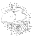
図1は本発明の一実施形態に係るドレスガードを備えた自動二輪車の後部の側面図である。同図に示す自動二輪車の車体フレームFRは、前半部を構成するメインフレーム1と、メインフレーム1の後部に連結されて車体フレームFRの後半部を構成するリヤフレーム2とを有している。リヤフレーム2は、後方に向かって上方に傾斜して延びている。メインフレーム1の前端部に図示しないフロントフォークを介して前輪が支持されている。
FIG. 1 is a side view of a rear portion of a motorcycle including a dress guard according to an embodiment of the present invention. A vehicle body frame FR of the motorcycle shown in the figure has a main frame 1 constituting the front half part and a
メインフレーム1の後端下部のスイングアームブラケット4にスイングアーム6が上下揺動自在に支持されている。スイングアーム6の後端部に後輪8が支持されている。メインフレーム1の下方でスイングアームブラケット4の前方にエンジンEが配置され、メインフレーム1に支持されている。エンジンEが、チェーンのような動力伝達部材10を介して後輪8を駆動する。エンジンEの排気ガスGは排気管13を介してマフラ15に導入され、マフラ15が排気ガスGを消音して外部に放出する。マフラ15は後輪8の両側方に、配置されている。
A
リヤフレーム2にライダー用シート12および同乗者用シート14が支持されている。同乗者用シート14の下方で、リヤフレーム2に、同乗者用シート14の下部の外周を覆うシートカバー16が取り付けられている。リヤフレーム2の下部を下方および側方から覆うリヤフェンダ18が、シートカバー16の下方でリヤフレーム2に取り付けられている。
A rider's
シートカバー16およびリヤフェンダ18の外側方に、同乗者が把持する左右一対のサイドグリップ20が配置されている。サイドグリップ20は、前後方向に長い長尺状の部材であり、その前後方向両端部の被支持部22、22と、これら被支持部22、22の間のグリップ部24とを有している。被支持部22、22は車体に支持される部位で、グリップ部24は同乗者が把持する部位である。各被支持部22,22がボルト25を用いてリヤフレーム2支持されている。
A pair of left and
リヤフレーム2に、同乗者の足を載せる同乗者ステップ26を支持する左右一対のステップステー28が取り付けられている。同乗者ステップ26は、マフラ15の上方に配置されている。本実施形態では、ステップステー28は、2つのボルト29によりリヤフレーム2に取り付けられている。車体の後端部にリヤフラップ32が設けられ、リヤフェンダ18に支持されてリヤフェンダ18の下面から後方斜め下方に延びている。
A pair of left and right step stays 28 for supporting a
自動二輪車の後部の一側方である左側方に、ドレスガード30が装着されている。ドレスガード30は、同乗者が前方を向いて乗車する鞍乗りではなく、左側方を向いて乗車する横乗りで乗車した際に、同乗者の衣類が後輪に干渉するのを防ぐことを目的として設けられる。ドレスガード30は、同乗者シート14の下方の左側方でマフラ15の上方に配置された第1ガード体34と、第1ガード体34の下方で後輪8の左側方に配置された第2ガード体36とを有している。ドレスガード30は、さらに、第1ガード体34の内側に配置され、第1および第2ガード体34、36を補強する補強体38を有している。本実施形態では、第1および第2ガード体34、36は、補強体38を介して車体に支持されている。ドレスガード30の支持構造については後述する。
A
第1ガード体34は、例えば、鋼製のパイプを折り曲げ加工することにより形成され、側面視で上方に開口し、図2の平面視で車体内側に開口したU字形状を有している。詳細には、第1ガード体34は、U字形の2つの第1および第2枝部34a,34bが前後方向に並んで配置され、U字形の基部34cが前後方向に延びている。ただし、第1ガード体34の形状は、U字形状に限定されず、例えば、環状であってもよい。第1ガード体34は、前側の第1枝部34aと後側の第2枝部34bとで補強体38を介して車体に支持され、基部34cが車体外側方に離れた位置を前後方向に延びている。
The
詳細には、前側の第1枝部34aは、マフラ15の後端の2つの排出口15a,15aよりも前方に位置している。これにより、マフラ15から後方に排出される排気ガスGに干渉しない。また、車体の幅方向内側から外側に向かって、同乗者シート14、サイドグリップ20および第1ガード体34の外縁部34cの順に配置されている。これにより、同乗者シート14が着座した同乗者が、サイドグリップ20を把持した状態で、第1ガード体34の外縁部34cに脚を掛けることができる。したがって、同乗者の乗車姿勢が安定する。
Specifically, the
図2に示す第1ガード体34の基部34cが第1ガード体34の外縁部を構成し、この第1ガード体34の外縁部34cがマフラ15よりも車体外側方に位置している。また、第1ガード体34の外縁部34cは、同乗者ステップ26よりも車体外側方に位置している。これにより、転倒時に、同乗者ステップ26が地面に触れるのを防止して、同乗者ステップ26を保護できる。
A
図1に示すように、リヤフレーム2が後方に向かって上方に傾斜して延びているのに対し、第1ガード体34の外縁部34cは前後方向に水平に延びている。また、側面視で、上方から同乗者シート14の上面、サイドグリップ20の把持部24および第1ガード体34の外縁部34cの順に配置されている。これにより、同乗者シート14に着座した同乗者が、サイドグリップ20を把持し易く、かつ、第1ガード体34の外縁部34cに脚を掛け易い。したがって、同乗者の乗車姿勢が安定する。さらに、側面視で、第1ガード体34の外縁部34cとサイドグリップ20の被支持部22とが上下方向にずれて配置されている。
As shown in FIG. 1, the
背面図である図3に示すように、第1ガード体34は、車体外側方に向かって下方に傾斜して延びており、第1ガード体34の外縁部(基部)34cが第1ガード体34の下縁部を構成し、この第1ガード体34の外縁部(下縁部)34cが、サイドグリップ20の下方でマフラ15の上方、かつ外側方に位置している。これにより、同乗者の衣服および脚がマフラ15およびマフラ15からの排気ガスG(図1)に接触するのを防止することができる。
As shown in FIG. 3, which is a rear view, the
図1に示すように、第1ガード体34の前端34dは、同乗者ステップ26より後方に位置する。これにより、同乗者は、横向きだけでなく、前向きに乗車可能となる。第1ガード体34の前端34dは、同乗者シート14の上面の着座部の前端14aよりも若干前方に位置している。これにより、横乗り状態で着座した同乗者の脚を第1ガード体34から前方にはみ出すことなく確実に第1ガード体34に掛けることができる。
As shown in FIG. 1, the
一方、第1ガード体34の後端34eは、本実施形態では、同乗者シート14の後端14bよりも若干後方に位置している。これにより、横乗り状態で着座した同乗者の脚を第1ガード体34から後方にはみ出すことなく確実に第1ガード体34に掛けることができる。第1ガード体34の後端34eは、マフラ15の排気ガスGから脚を保護できる位置で、かつ、同乗者が足(足の裏)を載せることができない位置に設定されることが好ましい。これにより、排気ガスGから脚を保護しつつ、第1ガード体34に過度な荷重が掛かるのを回避できる。また、第1ガード体34の後端34eは、リヤフラップ32の後端32aよりも前方に位置している。
On the other hand, the
第2ガード体36は、同乗者シート14および第1ガード体34の下方で後輪8の上半分を外側方から覆っており、本実施形態では、後輪8の軸心8aよりも上方で後方の部分を覆っている。図3に示すように、第2ガード体36は、マフラ15よりも車体内側に配置されている。第2ガード体36は、背面視で、上下方向にほぼ真っ直ぐ伸びている。これにより、マフラ15の内側で後輪8の外側の狭い空間に配置しやすい。第2ガード体36は、衣服が後輪8に干渉するのを防止する。第2ガード体36は、第1ガード体34に弾性体40を介して連結されている。第1ガード体34と第2ガード体36との連結構造については後述する。
The
図1に示す第2ガード体36は、鋼製のパイプを折り曲げ加工してその両端部を溶接することにより形成されたループ状の外枠42を有している。本実施形態では、外枠42は側面視で五角形状である。外枠42の内部に、鋼製のパイプからなる複数の縦方向保護部材43および横方向保護部材44が格子状に配置され、外枠42に溶接で連結されている。本実施形態では、縦方向保護部材43が横方向保護部材44の車幅方向外側に配置されている。縦方向保護部材43および横方向保護部材44の間隔は、同乗者の衣服と後輪8との干渉を回避できる大きさに設定されている。
The
補強体38は、前部がリヤフレーム2に支持され、後部がリヤフェンダ18の下面に設けた支持体45に支持されている。詳細には、補強体38は、第1ガード体34の車体内側でリヤフレーム2に沿って延びる前後連結部材46と、前後連結部材46の後部と支持体45とを連結する後部連結部材48と、第1ガード体34の車体内側に位置するU字形状の補強基材50とを有している。
The reinforcing
前後連結部材46は、鋼製のパイプからなり、リヤフレーム2、すなわち車体後部に沿って斜め前後方向に延びている。前後連結部材46の前端部に、第1枝部34aの先端部が溶接により連結され、前後連結部材46の後端部に、第2枝部34bの先端部が溶接により連結されている。つまり、前後連結部材46により、第1ガード体34の前部の上端部と後部の上端部とが連結されている。
The front /
前後連結部材46と第1ガード体34の基部34cとは、斜め上下方向に延びる複数のバー部材52により連結されている。各バー部材52は、棒状の鋼材からなり、その両端が前後連結部材46と第1ガード体34の基部34cとに溶接で固着されている。複数のバー部材52は、前後方向に並んで配置されており、図2の平面視で、前後連結部材46および第1ガード体34の基部34cにほぼ直交している。複数のバー部材52を設けることにより、第1ガード体34の基部34cに同乗者が足を載せることができないようにしている。その結果、第1ガード体34の強度を過度に大きくする必要がなくなり、第1ガード体34がシンプルで軽量化する。
The front-
図1の後部連結部材48は、鋼製のパイプからなり、リヤフェンダ18の下面に設けた支持体45から車幅方向外側に向かって延びている。本実施形態では、支持体45は、鋼製の板材からなる直方体形状の支持ボックスであり、リヤフラップ32とともに複数のボルト(図示せず)によりリヤフレーム2に共締めされている。支持体45には、同乗者シート14の後方にオプションとして配置されるトップケース(図示せず)を支持する支持部材54がボルト(図示せず)により固定される。
The
後部連結部材48の車幅方向外側端は、前後連結部材46の後端部に溶接により連結されている。詳細には、後部連結部材48の車幅方向外側端は、前後連結部材46における第1ガード体34の第2枝部34bの先端部が連結される個所の近傍に連結されている。つまり、後部連結部材48は、第1ガード体34の後部の上端部と支持体45とを連結し、第1ガード体34の後部を補強する。
The outer end in the vehicle width direction of the
補強基材50は、側面視でほぼ上方に開口するU字形状で、鋼製のパイプを折り曲げることで形成されている。具体的には、U字形状の補強基材50は、前側の第1枝部56と、後側の第2枝部58と、両枝部56,58を連結し前後連結部材46とほぼ平行に延びる底部60とを有している。前側の第1枝部56の先端部56aは、前後連結部材46の前端部に溶接により連結されている。詳細には、第1枝部56の先端部56aは、前後連結部材46における第1ガード体34の第1枝部34aの先端部が連結される個所の近傍に連結されている。
The reinforcing
後側の第2枝部58の先端部58aは、前後連結部材46の後端部に溶接により連結されている。詳細には、第2枝部58の先端部58aは、前後連結部材46における第1ガード体34の第2枝部34bの先端部が連結される個所の近傍に連結されている。このように、補強基材50は、第1ガード体34の前部の上端部と後部の上端部とを連結し、第1ガード体34の上端部を補強する。
The
図4に示すように、第1ガード体34の基部34cの前端部と補強基材50の底部60の前端部とが、第1補強パイプ62により連結されている。これにより、第1ガード体34の下端部の前部が補強されている。一方、第1ガード体34の基部34cの後端部と補強基材50の底部60の後端部とが第2補強パイプ64により連結されている。また、補強基材50の底部60の後端部と後部連結部材48とが第3補強パイプ66により連結されている。これにより、第1ガード体34の下端部の後部が補強されている。なお、図4では、サイドグリップ20は省略されている。
As shown in FIG. 4, the front end portion of the
このように、第1ガード体34と補強体38とは溶接により一体化され、サブアッシSAを構成している。このサブアッシSAにおいて、図1に示す車体内側の前後連結部材46および補強基材50の底部60は、車体後部に沿って後方に向かって上方に傾斜して延びており、車体外側の第1ガード体34の外縁部34cは前後方向に水平に延びている。したがって、側面視では、前後連結部材46と第1ガード体34の外縁部34cは後方に向かって上下方向に離れるように延びているが、図2の平面視では、平行に延びている。ただし、第1ガード体34の外縁部34cを、車体後部に沿って後方に向かって上方に傾斜して延びるように、すなわち前後連結部材46と平行にしてもよい。
Thus, the
つぎに、このサブアッシSAの車体への取り付けについて説明する。図1の補強体38の前後連結部材46の前端部が、共通の締結部材である前記ボルト25を用いて、サイドグリップ20とともにリヤフレーム2に支持されている。詳細には、前後連結部材46の前端部に、取付金具68が溶接により固着されており、取付金具68に設けたボルト挿通孔68aとサイドグリップ20の前側の被支持部22に設けたボルト挿通孔22aの順に、車体の外側方からボルト25が挿通され、リヤフレーム2に形成したねじ孔(図示せず)に締め付けられる。これにより、サブアッシSAの前部の上部が車体に支持される。
Next, attachment of the sub assembly SA to the vehicle body will be described. The front end of the front /
補強体38の後部連結部材48が、ボルト70を用いて支持体45に支持されている。詳細には、後部連結部材48の車幅方向内側端部に取付金具72が溶接により固着されており、取付金具72に設けたボルト挿通孔72aに車体の外側方からボルト70が挿通され、支持体45に形成したねじ孔(図示せず)に締め付けられる。これにより、サブアッシSAの後部が車体に支持される。
The
補強体38の補強基材50がステップステー28に支持されている。詳細には、ステップステー28の後端部に、後方に突出した支持部69が形成され、支持部69に支持片71が装着されている。支持片71は、板金を折り曲げることで形成され、図4に示す下方に開口したU字形状の装着部74と、装着部74から後方に突出した左右一対の係止部76とを有している。支持片71は、装着部74でステップステー28の支持部69に装着されるとともに、係止部76で補強基材50の前側の第1枝部56を把持する。これにより、サブアッシSAの前部の下部が車体に支持される。以上により、第1ガード体34が補強体38を介して車体に弾性体を介さずに支持される。
The reinforcing
このように、ドレスガード30は、図1のサイドグリップ20の取付座、トップケース取付用支持体45、ステップステー28の既存の支持部、ステー等を利用して車体に取り付けられている。つまり、ドレスガード30の取付け用に専用のブラケットを設けていない。したがって、車体の変更なしで、ドレスガード30ありのモデルと、なしのモデルの切換えが容易である。
As described above, the
第2ガード体36は、弾性体40を介したラバーマウントにより第1ガード体34および補強体38に取り付けられている。詳細には、第1ガード体34の前部と第2ガード体36の前部とをラバーマウントにより連結する前部支柱78と、第1ガード体34の後部と第2ガード体36の後部とをラバーマウントにより連結する後部支柱80とが設けられている。さらに、補強体38の補強基材50の前後方向中間部と第2ガード体36の前後方向中間部とをラバーマウントにより連結する連結ユニット82が設けられている。このように、前部、前後方向中間部、後部の3箇所で第2ガード体36を支持することで、第2ガード体36の支持が安定する。
The
図4に示すように、前部支柱78は、第1ガード体34の基部34cにおける第1補強パイプ62が連結される部位の近傍に連結されている。また、後部支柱80は、第1ガード体34の基部34cにおける第2補強パイプ64が連結される部位の近傍に連結されている。これにより、前部支柱78および後部支柱80を介した第2ガード体36の支持が安定する。
As shown in FIG. 4, the
第1ガード体34の基部34cの前部に、円筒状の弾性体40を介して支持部材79が装着され、支持部材79と前部支柱78の上端部78aとがボルト81により連結されている。弾性体40は、ゴムのような弾性材料からなる。支持部材79は、弾性体40を覆う円環部79aと、これから延出された舌片部79bとを有している。ボルト81が舌片部79bに挿通され、舌片部79bの裏面の固着された溶接ナット(図示せず)にねじ込まれている。これにより、基部34cと前部支柱78が連結されている。前部支柱78の下端部78bは第2ガード体36の上端部に溶接で接合されている。
A
同様に、第1ガード体34の基部34cの後部に、円筒状の弾性体40を介して支持部材79が装着され、支持部材79と後部支柱80の上端部80aとがボルト81により連結されている。後部支柱80の下端部80bは第2ガード体36の上端部に溶接で接合されている。
Similarly, a
連結ユニット82は、補強基材50の底部60の前後方向中間部と第2ガード体36の上端部の前後方向中間部とを連結する。図5は、連結ユニット82の縦断面図である。同図に示すように、連結ユニット82は、下端部に第2ガード体36が接合された連結部材84と、弾性体40を介して連結部材84に補強基材50の底部60を固定する支持部材86とを有している。
The connecting
連結部材84は、上下方向に長い矩形の板金からなり、その下端部84aが車幅方向外側に折り曲げられている。この下端部84aが、第2ガード体36の前後方向中央部に溶接により接合されている。連結部材84には、上下方向に並んで2つのねじ孔84bが形成されている。本実施形態では、ねじ孔84bは溶接ナットにより形成されている。
The connecting
支持部材86は、矩形の板金を折り曲げ加工することにより形成されている。詳細には、連結部材84との取付部88と、連結部材84から離れるように車体外側方に膨出して補強基材50の底部60を把持する把持部90とを有している。取付部88は、上端部および下端部に2箇所設けられ、把持部90は、両取付部88,88の間に位置している。把持部90は、円筒形状の補強基材50の外形にほぼ沿った形状である。各取付部88におけるねじ孔84bに対応する位置に、車幅方向を向いたボルト挿通孔88aが形成されている。
The
支持部材86の把持部90に、円筒状の弾性体40を介して補強基材50の底部60が把持されている。弾性体40は、ゴムのような弾性材料からなる。ボルト85が、車体外側から各取付部88のボルト挿通孔88aに挿通され、連結部材84のねじ孔84bに締め付けられている。これにより、補強基材50の底部60が連結部材84に固定され、補強基材50と第2ガード体36とが弾性体40を介して連結される。
The
上記構成によれば、図3に示すドレスガード30の第1ガード体34がマフラ15の上方に位置し、しかも、第1ガード体34の外縁部34cがマフラ15よりも車体外側方に位置している。これにより、同乗者が横乗りで乗車した場合でも、マフラ15からの排気ガスG(図1)が同乗者の衣服および脚の下方を通過するので、同乗者の衣服および脚が排気ガスGから保護される。
According to the above configuration, the
また、第1ガード体34の外縁部34cが、サイドグリップ20のグリップ部24の下方に位置している。したがって、同乗者がサイドグリップ20を把持した状態で乗車しやすいので、横乗りで乗車した同乗者の姿勢が安定する。
Further, the
図1に示すように、自動二輪車の後部は、前方に向かって下方に傾斜しているので、同乗者が横乗りで乗車すると、同乗者の姿勢が前寄りになり易い。本実施形態では、第1ガード体34の外縁部34cが前後方向に水平に延びているので、第1ガード体34の外縁部34cに脚を掛けることで、同乗者の姿勢が前寄りになることが緩和され、同乗者の姿勢が維持される。
As shown in FIG. 1, the rear part of the motorcycle is inclined downward toward the front, so that when the passenger gets on the vehicle sideways, the passenger's posture tends to be forward. In the present embodiment, since the
ドレスガード30の上端部の前部が、共通の締結部材であるボルト25を用いて、サイドグリップ20とともにリヤフレーム2に支持されている。これにより、ボルト25の数量が低減するうえに、組立工数も少なくなる。しかも、第1ガード体34の外縁部34cとサイドグリップ20の被支持部22とが上下方向にずれて配置されているので、第1ガード体34の外縁部34cがボルト25の締結作業の邪魔にならない。
The front portion of the upper end portion of the
また、ドレスガード30の下部の前部が同乗者ステップステー28の支持部69に支持され、後部がリヤフェンダ18の下面に設けた支持体45に支持されている。このように、ドレスガード30が、前部と後部とで車体に支持されるので、ドレスガード30の支持が安定する。このように、既存のステー、支持体等を利用してドレスガード30が取り付けられているので、ドレスガード30を取り外すことで、ドレスガードなしのモデルに容易に切り換えることができる。
The lower front portion of the
第1ガード体34は、車体から外側方に突出して、前後方向に長い形状をしており、横乗り状態の同乗者の脚が掛けられることで、車体内側斜め下方に負荷がかかる。上記構成では、車体に支持されて第1ガード体34を補強する補強体38(46,48,50)が設けられ、補強体38により第1ガード体34の前部の上端部と後部の上端部とが車体内側から補強されている。これにより、第1ガード体34の前部および後部が車体内側から補強体38により補強されるので、第1ガード体34が車体内側斜め下方に倒れるのを効果的に抑制できる。
The
また、第1ガード体34および補強体38に弾性体40を介して、後輪8の外側方を覆う第2ガード体36が連結されている。これにより、第1ガード体34で、同乗者の衣服および脚を排気ガスGから保護するとともに、第2ガード体36で、同乗者の衣類が後輪8に干渉するのを回避できる。
Further, a
ドレスガード30を一体物で構成すると、上端部が車体に支持された上下方向に長い単一の部材で構成されることになるので、振動が大きくなることが懸念される。上記構成によれば、ドレスガード30を第1および第2ガード体34,36からなる2ピース構造とし、両ガイド体34,36が弾性体40を介して連結されている。したがって、車体からの振動が第2ガード体36に伝達されるのを防ぐことができるうえに、ドレスガード30の振幅を小さくできる。また、ドレスガード30を一体物で構成すると、1つの部品が大きくなるので、製造、運搬、保管が困難になるうえに、車体への取付け、取外しも手間がかかる。
If the
第1ガード体34は、車体に固定されるとともに、同乗者の脚が掛けられる部位であるから、高い剛性が求められる一方で、第2ガード体36は、同乗者の衣類と後輪8の干渉を防ぐ部位であり、第1ガード体34に比べて剛性は低くてもよい。上記構成では、ドレスガード30を第1および第2ガード体34,36からなる2ピース構造とすることで、各ガード体34,36に要求される強度に応じて部材の材質、外径、板厚等を変えることができるので、一体物で構成される場合に比べて、ドレスガード30の小形化、軽量化を図ることができる。
Since the
上記実施形態では、第1ガード体34の外縁部34cは前後方向に水平に延びていたが、車体後部に沿って前下がりに傾斜して延びるようにしてもよい。この場合、同乗者の姿勢は前寄りになるが、ステップ26に足を載せることで、姿勢を安定させることができる。また、図6に示すように、ステップステー28におけるステップ26が取り付けられる取付部95に、水平な上面を有する足台100を着脱自在に取り付けてもよい。足台100には、横向きに乗車した同乗者の片足または両足が載せられる。必要に応じて、足台100にヒートガードを設けて、マフラ15の熱から足を保護するようにしてもよい。
In the above-described embodiment, the
この構成によれば、横乗りの同乗者の膝付近の内側を第1ガード体34に掛けるとともに、足の裏を足台100に載せることができる。これにより、同乗者の姿勢が安定し、しかも足が疲れない。
According to this configuration, the inner side in the vicinity of the knee of the side passenger can be hung on the
本発明は、以上の実施形態に限定されるものでなく、本発明の要旨を逸脱しない範囲内で、種々の追加、変更または削除が可能である。例えば、第1ガード体34の十分な支持強度が確保される場合、補強体38はなくてもよい。その場合、第1ガード体34が車体に直接支持される。さらに、マフラ15はドレスガード30が配置される一側方に配置されていればよく、両側方になくてもよい。したがって、そのようなものも本発明の範囲内に含まれる。
The present invention is not limited to the above-described embodiment, and various additions, modifications, or deletions can be made without departing from the gist of the present invention. For example, when sufficient support strength of the
2 リヤフレーム
8 後輪
14 同乗者シート
15 マフラ
18 リヤフェンダ
20 サイドグリップ
24 グリップ部
25 ボルト(共通の締結部材)
26 同乗者ステップ
30 ドレスガード
34 第1ガード体
34c 基部(第1ガード体の外縁部)
36 第2ガード体
38 補強体
40 弾性体
45 支持体
46 前後連結部材
48 後部連結部材
50 補強基材
56a,58a 補強基材の先端部
60 底部
69 同乗者ステップの支持部
100 足台
2
26
36
Claims (7)
同乗者シートの前記一側方で前記マフラの上方に、第1ガード体を備え、
前記第1ガード体の外縁部は、前記マフラよりも車体外側方に位置し、
前記第1ガード体の外縁部が、自動二輪車のリヤフレームに支持されたサイドグリップのグリップ部の下方に位置している自動二輪車のドレスガード。 A dress guard attached to a motorcycle having a muffler on at least one side of the rear part,
A first guard body is provided above the muffler at the one side of the passenger seat,
The outer edge of the first guard body is located on the outer side of the vehicle body than the muffler,
A dress guard for a motorcycle, wherein an outer edge portion of the first guard body is located below a grip portion of a side grip supported by a rear frame of the motorcycle.
同乗者シートの前記一側方で前記マフラの上方に、第1ガード体を備え、
前記第1ガード体の外縁部は、前記マフラよりも車体外側方に位置し、
前記ドレスガードの前部が自動二輪車の同乗者の足を載せる同乗者ステップまたは前記同乗者ステップの支持部に支持され、一部がリヤフェンダの下面に設けた支持体に支持されている自動二輪車のドレスガード。 A dress guard attached to a motorcycle having a muffler on at least one side of the rear part,
A first guard body is provided above the muffler at the one side of the passenger seat,
The outer edge of the first guard body is located on the outer side of the vehicle body than the muffler,
A motorcycle in which a front portion of the dress guard is supported by a passenger step on which a passenger of a motorcycle is to be placed or a support portion of the passenger step, and a part thereof is supported by a support provided on a lower surface of a rear fender. Dress guard.
同乗者シートの前記一側方で前記マフラの上方に、第1ガード体を備え、
前記第1ガード体の外縁部は、前記マフラよりも車体外側方に位置し、
前記ドレスガードが、共通の締結部材を用いて、サイドグリップとともに自動二輪車のリヤフレームに支持されている自動二輪車のドレスガード。 A dress guard attached to a motorcycle having a muffler on at least one side of the rear part,
A first guard body is provided above the muffler at the one side of the passenger seat,
The outer edge of the first guard body is located on the outer side of the vehicle body than the muffler,
A dress guard for a motorcycle, wherein the dress guard is supported by a rear frame of the motorcycle together with a side grip using a common fastening member.
同乗者シートの前記一側方で前記マフラの上方に、第1ガード体を備え、
前記第1ガード体の外縁部は、前記マフラよりも車体外側方に位置し、
さらに、自動二輪車のリヤフレームとリヤフェンダの下面に設けた支持体とに支持されて前記第1ガード体を補強する補強体を備え、
前記補強体は、前記第1ガード体の前部の上端部と後部の上端部とを連結する前後連結部材と、前記前後連結部材の後部と前記支持体とを連結する後部連結部材と、前記第1ガード体の車体内側に位置する補強基材とを有し、
前記補強基材は、前記前後連結部材の前部と後部とに連結された2つの先端部と、前記前後連結部材とほぼ平行な底部とを有している自動二輪車のドレスガード。 A dress guard attached to a motorcycle having a muffler on at least one side of the rear part,
A first guard body is provided above the muffler at the one side of the passenger seat,
The outer edge of the first guard body is located on the outer side of the vehicle body than the muffler,
And a reinforcing body that is supported by a rear frame of the motorcycle and a support body provided on a lower surface of the rear fender and reinforces the first guard body,
The reinforcing body includes a front / rear connecting member that connects an upper end portion of a front portion and a rear upper end portion of the first guard body, a rear connecting member that connects a rear portion of the front / rear connecting member and the support body, A reinforcing base material located on the inner side of the first guard body,
The dressing guard for a motorcycle, wherein the reinforcing base member has two front end portions connected to a front portion and a rear portion of the front / rear connecting member, and a bottom portion substantially parallel to the front / rear connecting member.
同乗者シートの前記一側方で前記マフラの上方に、第1ガード体を備え、
前記第1ガード体の外縁部は、前記マフラよりも車体外側方に位置し、
前記第1ガード体に弾性体を介して、後輪の前記一側方に配置された第2ガード体が連結されている自動二輪車のドレスガード。 A dress guard attached to a motorcycle having a muffler on at least one side of the rear part,
A first guard body is provided above the muffler at the one side of the passenger seat,
The outer edge of the first guard body is located on the outer side of the vehicle body than the muffler,
A dress guard for a motorcycle, wherein a second guard body arranged on the one side of the rear wheel is connected to the first guard body via an elastic body.
同乗者シートの前記一側方で前記マフラの上方に、第1ガード体を備え、
前記第1ガード体の外縁部は、前記マフラよりも車体外側方に位置し、
自動二輪車の同乗者の足を載せる同乗者ステップに、水平な上面を有する足台が着脱自在に取り付けられている自動二輪車のドレスガード。 A dress guard attached to a motorcycle having a muffler on at least one side of the rear part,
A first guard body is provided above the muffler at the one side of the passenger seat,
The outer edge of the first guard body is located on the outer side of the vehicle body than the muffler,
A motorcycle dress guard in which a footrest having a horizontal upper surface is detachably attached to a passenger step on which a passenger of a motorcycle is placed.
Priority Applications (1)
| Application Number | Priority Date | Filing Date | Title |
|---|---|---|---|
| JP2015252439A JP6576236B2 (en) | 2015-12-24 | 2015-12-24 | Motorcycle dress guard |
Applications Claiming Priority (1)
| Application Number | Priority Date | Filing Date | Title |
|---|---|---|---|
| JP2015252439A JP6576236B2 (en) | 2015-12-24 | 2015-12-24 | Motorcycle dress guard |
Publications (2)
| Publication Number | Publication Date |
|---|---|
| JP2017114332A JP2017114332A (en) | 2017-06-29 |
| JP6576236B2 true JP6576236B2 (en) | 2019-09-18 |
Family
ID=59233176
Family Applications (1)
| Application Number | Title | Priority Date | Filing Date |
|---|---|---|---|
| JP2015252439A Active JP6576236B2 (en) | 2015-12-24 | 2015-12-24 | Motorcycle dress guard |
Country Status (1)
| Country | Link |
|---|---|
| JP (1) | JP6576236B2 (en) |
Families Citing this family (5)
| Publication number | Priority date | Publication date | Assignee | Title |
|---|---|---|---|---|
| JP6742972B2 (en) * | 2017-09-27 | 2020-08-19 | 本田技研工業株式会社 | Saddle-type vehicle cover member structure |
| JP6861665B2 (en) * | 2018-04-13 | 2021-04-21 | 本田技研工業株式会社 | Saddle-riding vehicle |
| JP6861744B2 (en) * | 2018-04-23 | 2021-04-21 | 本田技研工業株式会社 | Guard member |
| JP6905546B2 (en) * | 2018-05-30 | 2021-07-21 | 本田技研工業株式会社 | Saddle-type vehicle |
| JP2021054129A (en) * | 2019-09-27 | 2021-04-08 | ヤマハ発動機株式会社 | Saddle-riding vehicle |
Family Cites Families (6)
| Publication number | Priority date | Publication date | Assignee | Title |
|---|---|---|---|---|
| JPS62155076U (en) * | 1986-03-24 | 1987-10-01 | ||
| JPH0442227Y2 (en) * | 1987-01-27 | 1992-10-05 | ||
| JPS6455187U (en) * | 1987-10-01 | 1989-04-05 | ||
| JP4209489B2 (en) * | 1998-02-20 | 2009-01-14 | 本田技研工業株式会社 | Body cover structure for motorcycles |
| JP5782403B2 (en) * | 2012-03-30 | 2015-09-24 | 本田技研工業株式会社 | Grab rail layout |
| JP2015016802A (en) * | 2013-07-11 | 2015-01-29 | スズキ株式会社 | Motor cycle |
-
2015
- 2015-12-24 JP JP2015252439A patent/JP6576236B2/en active Active
Also Published As
| Publication number | Publication date |
|---|---|
| JP2017114332A (en) | 2017-06-29 |
Similar Documents
| Publication | Publication Date | Title |
|---|---|---|
| JP6576236B2 (en) | Motorcycle dress guard | |
| EP1634803A1 (en) | Rider restraining device for two wheel vehicle | |
| JP6288524B2 (en) | Saddle riding | |
| JP5835690B2 (en) | Saddle riding | |
| JP6045903B2 (en) | Motorcycle | |
| JP2009286262A (en) | Motorcycle | |
| JP6106482B2 (en) | Saddle riding vehicle | |
| JP5460511B2 (en) | Rear fender for vehicles | |
| JP6962892B2 (en) | Saddle-type vehicle | |
| JP5396210B2 (en) | Motorcycle side bag support stay | |
| JP6799952B2 (en) | Pannier mounting structure for saddle-mounted vehicles | |
| JP5806643B2 (en) | Body cover structure for saddle-ride type vehicles | |
| JP2015085743A (en) | Reinforcement structure of front fender | |
| JP6448157B2 (en) | Motorcycle headlight guard structure | |
| JP4503519B2 (en) | Vehicle fuel tank arrangement structure | |
| JP6363445B2 (en) | Rear structure of motorcycle | |
| CN110316295B (en) | Seat frame for saddle-riding type vehicle | |
| JP6997692B2 (en) | Saddle-type vehicle | |
| JP5702667B2 (en) | Step structure of saddle riding type vehicle | |
| US9598130B2 (en) | Rear fender for vehicle | |
| JP6395537B2 (en) | Motorcycle pannier mounting structure | |
| JP2008062813A (en) | Riding type vehicle | |
| WO2017134832A1 (en) | Saddle-type vehicle | |
| JP6761287B2 (en) | Rear frame structure of saddle-mounted vehicle | |
| JP2013075553A (en) | Pannier case mounting structure for straddle type vehicle |
Legal Events
| Date | Code | Title | Description |
|---|---|---|---|
| A621 | Written request for application examination |
Free format text: JAPANESE INTERMEDIATE CODE: A621 Effective date: 20180620 |
|
| A977 | Report on retrieval |
Free format text: JAPANESE INTERMEDIATE CODE: A971007 Effective date: 20190410 |
|
| A131 | Notification of reasons for refusal |
Free format text: JAPANESE INTERMEDIATE CODE: A131 Effective date: 20190514 |
|
| A521 | Request for written amendment filed |
Free format text: JAPANESE INTERMEDIATE CODE: A523 Effective date: 20190530 |
|
| TRDD | Decision of grant or rejection written | ||
| A01 | Written decision to grant a patent or to grant a registration (utility model) |
Free format text: JAPANESE INTERMEDIATE CODE: A01 Effective date: 20190806 |
|
| A61 | First payment of annual fees (during grant procedure) |
Free format text: JAPANESE INTERMEDIATE CODE: A61 Effective date: 20190820 |
|
| R150 | Certificate of patent or registration of utility model |
Ref document number: 6576236 Country of ref document: JP Free format text: JAPANESE INTERMEDIATE CODE: R150 |
|
| S111 | Request for change of ownership or part of ownership |
Free format text: JAPANESE INTERMEDIATE CODE: R313111 |
|
| R350 | Written notification of registration of transfer |
Free format text: JAPANESE INTERMEDIATE CODE: R350 |
|
| R250 | Receipt of annual fees |
Free format text: JAPANESE INTERMEDIATE CODE: R250 |