JP6575652B2 - Image processing apparatus, image processing method, and program - Google Patents
Image processing apparatus, image processing method, and program Download PDFInfo
- Publication number
- JP6575652B2 JP6575652B2 JP2018164355A JP2018164355A JP6575652B2 JP 6575652 B2 JP6575652 B2 JP 6575652B2 JP 2018164355 A JP2018164355 A JP 2018164355A JP 2018164355 A JP2018164355 A JP 2018164355A JP 6575652 B2 JP6575652 B2 JP 6575652B2
- Authority
- JP
- Japan
- Prior art keywords
- image
- point
- captured image
- captured
- unit
- Prior art date
- Legal status (The legal status is an assumption and is not a legal conclusion. Google has not performed a legal analysis and makes no representation as to the accuracy of the status listed.)
- Active
Links
- 238000012545 processing Methods 0.000 title claims description 147
- 238000003672 processing method Methods 0.000 title claims description 7
- 238000003384 imaging method Methods 0.000 claims description 128
- 239000013598 vector Substances 0.000 claims description 113
- 230000033001 locomotion Effects 0.000 claims description 83
- 238000001514 detection method Methods 0.000 claims description 79
- 230000002093 peripheral effect Effects 0.000 claims description 25
- 238000004364 calculation method Methods 0.000 description 53
- 238000004891 communication Methods 0.000 description 42
- 230000006870 function Effects 0.000 description 42
- 230000010365 information processing Effects 0.000 description 35
- 238000010586 diagram Methods 0.000 description 30
- 230000015654 memory Effects 0.000 description 15
- 230000003287 optical effect Effects 0.000 description 12
- 238000000034 method Methods 0.000 description 11
- 238000005457 optimization Methods 0.000 description 8
- 230000008569 process Effects 0.000 description 7
- 239000000203 mixture Substances 0.000 description 6
- 239000004065 semiconductor Substances 0.000 description 4
- 238000004458 analytical method Methods 0.000 description 2
- 230000005540 biological transmission Effects 0.000 description 2
- 230000015572 biosynthetic process Effects 0.000 description 2
- 230000000295 complement effect Effects 0.000 description 2
- 230000000694 effects Effects 0.000 description 2
- 238000005401 electroluminescence Methods 0.000 description 2
- 229910044991 metal oxide Inorganic materials 0.000 description 2
- 150000004706 metal oxides Chemical class 0.000 description 2
- 230000004048 modification Effects 0.000 description 2
- 238000012986 modification Methods 0.000 description 2
- 239000013589 supplement Substances 0.000 description 2
- 230000001133 acceleration Effects 0.000 description 1
- 210000004556 brain Anatomy 0.000 description 1
- 230000008859 change Effects 0.000 description 1
- 238000006243 chemical reaction Methods 0.000 description 1
- 238000013500 data storage Methods 0.000 description 1
- 238000005516 engineering process Methods 0.000 description 1
- 239000000284 extract Substances 0.000 description 1
- 239000004973 liquid crystal related substance Substances 0.000 description 1
- 230000009467 reduction Effects 0.000 description 1
- 230000004044 response Effects 0.000 description 1
Images


Classifications
-
- G—PHYSICS
- G06—COMPUTING; CALCULATING OR COUNTING
- G06T—IMAGE DATA PROCESSING OR GENERATION, IN GENERAL
- G06T3/00—Geometric image transformation in the plane of the image
- G06T3/60—Rotation of a whole image or part thereof
-
- H—ELECTRICITY
- H04—ELECTRIC COMMUNICATION TECHNIQUE
- H04N—PICTORIAL COMMUNICATION, e.g. TELEVISION
- H04N23/00—Cameras or camera modules comprising electronic image sensors; Control thereof
- H04N23/80—Camera processing pipelines; Components thereof
-
- G06T3/047—
-
- G—PHYSICS
- G06—COMPUTING; CALCULATING OR COUNTING
- G06T—IMAGE DATA PROCESSING OR GENERATION, IN GENERAL
- G06T7/00—Image analysis
- G06T7/20—Analysis of motion
- G06T7/223—Analysis of motion using block-matching
- G06T7/231—Analysis of motion using block-matching using full search
-
- G—PHYSICS
- G06—COMPUTING; CALCULATING OR COUNTING
- G06T—IMAGE DATA PROCESSING OR GENERATION, IN GENERAL
- G06T7/00—Image analysis
- G06T7/20—Analysis of motion
- G06T7/223—Analysis of motion using block-matching
- G06T7/238—Analysis of motion using block-matching using non-full search, e.g. three-step search
-
- G—PHYSICS
- G06—COMPUTING; CALCULATING OR COUNTING
- G06T—IMAGE DATA PROCESSING OR GENERATION, IN GENERAL
- G06T7/00—Image analysis
- G06T7/70—Determining position or orientation of objects or cameras
- G06T7/73—Determining position or orientation of objects or cameras using feature-based methods
-
- H—ELECTRICITY
- H04—ELECTRIC COMMUNICATION TECHNIQUE
- H04N—PICTORIAL COMMUNICATION, e.g. TELEVISION
- H04N23/00—Cameras or camera modules comprising electronic image sensors; Control thereof
- H04N23/60—Control of cameras or camera modules
- H04N23/66—Remote control of cameras or camera parts, e.g. by remote control devices
- H04N23/661—Transmitting camera control signals through networks, e.g. control via the Internet
-
- G—PHYSICS
- G06—COMPUTING; CALCULATING OR COUNTING
- G06T—IMAGE DATA PROCESSING OR GENERATION, IN GENERAL
- G06T2207/00—Indexing scheme for image analysis or image enhancement
- G06T2207/10—Image acquisition modality
- G06T2207/10016—Video; Image sequence
-
- G—PHYSICS
- G06—COMPUTING; CALCULATING OR COUNTING
- G06T—IMAGE DATA PROCESSING OR GENERATION, IN GENERAL
- G06T2207/00—Indexing scheme for image analysis or image enhancement
- G06T2207/20—Special algorithmic details
- G06T2207/20021—Dividing image into blocks, subimages or windows
Description
本開示は、画像処理装置、画像処理方法およびプログラムに関する。 The present disclosure relates to an image processing device, an image processing method, and a program.
魚眼レンズを用いることによって、通常のレンズよりも広い画角の画像を撮像することができる。例えば魚眼レンズを鉛直方向に向けて撮像すれば、カメラの上方から全周までを含む画像を得ることができる。また、魚眼レンズを水平方向に向けて撮像すれば、上下および左右方向に広い範囲の画像を得ることができる。しかし、魚眼レンズを用いて撮像された画像にはひずみが生じるため、そのひずみの影響を除去して画像を利用するための技術が開発されてきた。例えば、特許文献1には、魚眼レンズを用いて撮像された画像を円筒面上に展開した展開画像に変換し、展開画像に基づいてオブジェクトまでの距離などを検出する技術が記載されている。 By using a fisheye lens, an image having a wider angle of view than a normal lens can be taken. For example, if an image is taken with the fisheye lens oriented in the vertical direction, an image including from the top of the camera to the entire circumference can be obtained. If the fisheye lens is imaged in the horizontal direction, a wide range of images can be obtained in the vertical and horizontal directions. However, since distortion occurs in an image captured using a fisheye lens, techniques for removing the influence of the distortion and using the image have been developed. For example, Patent Document 1 describes a technique for converting an image captured using a fisheye lens into a developed image developed on a cylindrical surface and detecting a distance to an object based on the developed image.
上記の通り魚眼レンズを用いて撮像された画像にはひずみが生じるが、このひずみは必ずしも観察者が脳内で補正することが困難なレベルのものではない。それゆえ、魚眼レンズを用いて撮像された画像をそのまま利用することも可能である。ところが、魚眼レンズを用いて撮像された画像を展開することなくそのまま利用するための技術は、これまで提案されてこなかった。 As described above, distortion occurs in an image captured using a fisheye lens, but this distortion is not necessarily at a level that is difficult for an observer to correct in the brain. Therefore, it is possible to use an image captured using a fisheye lens as it is. However, no technology has been proposed so far for using an image captured using a fisheye lens without developing it.
そこで、本開示では、魚眼レンズを用いて撮像された画像を展開せずに利用する場合により有用な画像を得ることを可能にする、新規かつ改良された画像処理装置、画像処理方法およびプログラムを提案する。 Therefore, the present disclosure proposes a new and improved image processing apparatus, image processing method, and program that make it possible to obtain a more useful image when an image captured using a fisheye lens is used without being developed. To do.
本開示によれば、魚眼レンズを介して時間的に連続して撮像される撮像画像を取得する画像取得部と、上記撮像画像における動きベクトルを取得するベクトル取得部と、上記動きベクトルの発生点または収束点を検出する点検出部とを含む画像処理装置が提供される。 According to the present disclosure, an image acquisition unit that acquires captured images that are sequentially captured through a fisheye lens, a vector acquisition unit that acquires a motion vector in the captured image, and a generation point of the motion vector or An image processing apparatus including a point detection unit for detecting a convergence point is provided.
また、本開示によれば、魚眼レンズを介して時間的に連続して撮像される撮像画像を取得することと、上記撮像画像における動きベクトルを取得することと、プロセッサが、上記動きベクトルの発生点または収束点を検出することとを含む画像処理方法が提供される。 Further, according to the present disclosure, acquiring a captured image that is continuously captured in time via a fisheye lens, acquiring a motion vector in the captured image, and a processor that generates the motion vector Alternatively, an image processing method including detecting a convergence point is provided.
また、本開示によれば、魚眼レンズを介して時間的に連続して撮像される撮像画像を取得する機能と、上記撮像画像における動きベクトルを取得する機能と、上記動きベクトルの発生点または収束点を検出する機能とをコンピュータに実現させるためのプログラムが提供される。 In addition, according to the present disclosure, a function of acquiring a captured image that is continuously captured through a fisheye lens, a function of acquiring a motion vector in the captured image, and a generation point or a convergence point of the motion vector A program for causing a computer to realize the function of detecting the above is provided.
撮像画像が魚眼レンズを介して時間的に連続して撮像される場合、撮像画像における動きベクトルの発生点や収束点は、例えば魚眼レンズを有するカメラが移動している方向を示すものでありうる。これらの点を検出して例えば撮像画像の編集や撮像の制御に利用することによって、観察しやすい有用な画像を得ることができる。 When the captured image is captured continuously in time via the fisheye lens, the motion vector generation point and convergence point in the captured image may indicate, for example, the direction in which the camera having the fisheye lens is moving. By detecting these points and using them, for example, for editing a captured image and controlling imaging, a useful image that is easy to observe can be obtained.
以上説明したように本開示によれば、魚眼レンズを用いて撮像された画像を展開せずに利用する場合により有用な画像を得ることができる。 As described above, according to the present disclosure, a more useful image can be obtained when an image captured using a fisheye lens is used without being developed.
以下に添付図面を参照しながら、本開示の好適な実施の形態について詳細に説明する。なお、本明細書および図面において、実質的に同一の機能構成を有する構成要素については、同一の符号を付することにより重複説明を省略する。 Hereinafter, preferred embodiments of the present disclosure will be described in detail with reference to the accompanying drawings. In the present specification and drawings, components having substantially the same functional configuration are denoted by the same reference numerals, and redundant description is omitted.
なお、説明は以下の順序で行うものとする。
1.第1の実施形態
1−1.機能構成
1−2.発生点および検出点の具体的な例
1−3.移動方向の推定
1−4.撮像画像の回転の例
2.第2の実施形態
3.第3の実施形態
4.第4の実施形態
5.第5の実施形態
5−1.機能構成
5−2.領域最適化の例
6.第6の実施形態
6−1.機能構成
6−2.記録制御の例
7.ハードウェア構成
8.補足
The description will be made in the following order.
1. 1. First embodiment 1-1. Functional configuration 1-2. Specific example of generation point and detection point 1-3. Estimation of moving direction 1-4. 1. Example of rotation of captured image Second embodiment 3. 3. Third embodiment 4. Fourth embodiment Fifth embodiment 5-1. Functional configuration 5-2. Example of region optimization Sixth Embodiment 6-1. Functional configuration 6-2. 6. Example of recording control Hardware configuration Supplement
(1.第1の実施形態)
(1−1.機能構成)
図1は、本開示の第1の実施形態に係る画像処理装置の概略的な機能構成を示すブロック図である。図1を参照すると、画像処理装置100は、通信部102と、記憶部104と、画像取得部106と、ベクトル算出部108と、点検出部110と、回転角度算出部112と、画像編集部114とを含む。さらに、画像処理装置100は、表示制御部116と、表示部118とを含んでもよい。
(1. First embodiment)
(1-1. Functional configuration)
FIG. 1 is a block diagram illustrating a schematic functional configuration of the image processing apparatus according to the first embodiment of the present disclosure. Referring to FIG. 1, an
本実施形態において、画像処理装置100は、ネットワークを介して他の装置から撮像画像を取得し、取得された画像を編集する装置である。画像処理装置100は、編集された画像を他の装置にネットワークを介して送信してもよいし、記憶部に蓄積してもよいし、あるいは自ら表示してもよい。
In the present embodiment, the
画像処理装置100は、例えば各種のPC(Personal Computer)、タブレット端末、携帯電話(スマートフォンを含む)、ゲーム機、またはメディアプレーヤなどの端末装置であってもよく、ネットワークを介して端末装置にサービスを提供するサーバであってもよい。画像処理装置100は、例えば後述する情報処理装置のハードウェア構成によって実現される。画像処理装置100がサーバである場合、画像処理装置100の機能はネットワークで接続された複数の情報処理装置が協働することによって実現されてもよい。以下、それぞれの構成要素についてさらに説明する。
The
通信部102は、例えば通信装置によって実現され、有線または無線の各種のネットワークを介して他の装置と通信する。例えば、通信部102は、他の装置から撮像画像のデータを受信して記憶部104に格納する。また、例えば、通信部102は、画像処理装置100において編集されて記憶部104に格納された画像のデータを他の装置に送信する。さらに、図示していないが、画像処理装置100がサーバである場合、通信部102は、サービスの提供を受ける端末装置から送信された処理の依頼などのコマンドを受信して画像処理装置100の各部に提供する。
The
記憶部104は、例えばストレージ装置および各種のメモリの組み合わせによって実現され、画像処理装置100で用いられる各種のデータを一時的または永続的に格納する。例えば、記憶部104は、通信部102が他の装置から受信した撮像画像のデータを少なくとも一時的に格納し、必要に応じて画像取得部106に提供する。また、例えば、記憶部104は、画像編集部114によって編集された画像のデータを少なくとも一時的に格納し、必要に応じて他の装置に送信するために通信部102に提供する。あるいは、記憶部104は、編集された画像のデータを表示のために表示制御部116に提供してもよい。
The
画像取得部106は、例えばCPU(Central Processing Unit)がメモリに格納されたプログラムに従って動作することによって実現され、記憶部104に格納された撮像画像のデータを取得する。ここで、画像取得部106によってデータが取得される撮像画像は、魚眼レンズを介して時間的に連続して撮像されたものである。ここで、魚眼レンズを介して撮像された撮像画像は、魚眼レンズを有するカメラの全周を含むため、全周画像ともいえる。これらの画像は、例えば動画像として一連のフレームを構成するものであってもよいし、独立して撮像された2枚以上の静止画であってもよい。
The
ベクトル算出部108は、例えばCPUがメモリに格納されたプログラムに従って動作することによって実現され、画像取得部106によって取得された撮像画像における動きベクトルを算出する。例えば、ベクトル算出部108は、撮像画像を所定のサイズのブロックに分割し、時間的に前後に位置する撮像画像の間でブロックマッチングを実行することによって動きベクトルを算出する。なお、動きベクトルの算出にはこれ以外にも公知のさまざまな手法を利用することが可能である。
The
ここで、ベクトル算出部108は、後述する点検出部110での処理結果に応じて2段階で動きベクトルを算出してもよい。この場合、例えば、ベクトル算出部108は、まず撮像画像の全体について第1のブロックサイズで動きベクトルを算出する。算出された動きベクトルは一旦点検出部110に提供され、点検出部110で動きベクトルに基づいて探索領域が設定される。次に、ベクトル算出部108は、撮像画像のうちの探索領域(その近傍を含んでもよい)について第1のブロックサイズよりも小さい第2のブロックサイズで動きベクトルを算出し、算出された動きベクトルを点検出部110に提供する。点検出部110は、探索領域において、より小さい第2のブロックサイズで算出された動きベクトルを用いて発生点または収束点を探索する。このように、ベクトル算出部108におけるブロックマッチングの実行回数を削減することによって、画像処理装置100全体としての処理負荷が軽減されうる。
Here, the
なお、他の実施形態では、ベクトル算出部108が画像処理装置100に含まれなくてもよい。つまり、画像処理装置100は、必ずしも動きベクトルを自ら算出しなくてもよい。例えば、動きベクトルは、他の装置で算出されてデータとして通信部102によって受信され、記憶部104に格納されてもよい。この場合、ベクトル算出部108は、撮像画像に対応する動きベクトルのデータを記憶部104から読み出すベクトル取得部によって代替されうる。
In other embodiments, the
点検出部110は、例えばCPUがメモリに格納されたプログラムに従って動作することによって実現され、ベクトル算出部108によって算出された動きベクトルの発生点または収束点を検出する。後述するように、魚眼レンズを介して時間的に連続して撮像された撮像画像では、カメラの移動方向に応じて動きベクトルの発生点または収束点が現れる。より具体的には、点検出部110は、撮像画像の周縁部で発生点および収束点の両方を検出するか、撮像画像の中央部で発生点または収束点のいずれかを検出しうる。
The
ここで、点検出部110は、上述したベクトル算出部108での2段階の動きベクトルの算出に対応して、2段階で発生点または収束点を検出してもよい。この場合、例えば、点検出部110は、まず撮像画像の全体について第1のブロックサイズで算出された動きベクトルに基づいて撮像画像中に探索領域を設定する。探索領域には、例えば、動きベクトルの大きさが相対的に小さい領域、または相対的に多くの動きベクトルの方向が交差する領域が設定されうる。これは、発生点および収束点の近傍では動きベクトルの大きさが小さくなり、また発生点および収束点には多くの動きベクトルの方向が集中するという、魚眼レンズを介して時間的に連続して撮像された撮像画像の特徴を反映したものである。点検出部110は探索領域の情報をベクトル算出部108に提供し、ベクトル算出部108は探索領域(その近傍を含んでもよい)についてより小さい第2のブロックサイズで動きベクトルを算出する。さらに、点検出部110は第2のブロックサイズで算出された動きベクトルに基づいて、探索領域の中で発生点または収束点を探索する。
Here, the
あるいは、ベクトル算出部108での動きベクトルの算出が2段階ではない場合でも、点検出部110は、上記の例と同様にして探索領域を設定し、探索領域の中で発生点または収束点を探索してもよい。この場合、点検出部110は、ベクトル算出部108によって算出された動きベクトルを第1の粒度で抽出して探索領域を設定し、探索領域の中で第1の粒度よりも細かい第2の粒度で動きベクトルを抽出して発生点または収束点を探索しうる。この場合も、探索領域には、例えば動きベクトルの大きさが相対的に小さい領域、または相対的に多くの動きベクトルの方向が交差する領域が設定されうる。
Alternatively, even when the motion vector calculation by the
なお、点検出部110によって検出される動きベクトルの発生点および収束点のより具体的な例については後述する。
Note that more specific examples of motion vector generation points and convergence points detected by the
回転角度算出部112は、例えばCPUがメモリに格納されたプログラムに従って動作することによって実現され、点検出部110によって撮像画像の周縁部で発生点が検出された場合に、発生点が撮像画像の中心に対して所定の向きに位置するような撮像画像の回転角度を算出する。より具体的には、回転角度算出部112は、発生点が撮像画像の中心に対して下に位置するように回転角度を算出しうる。このような回転角度は、後述するように、例えば撮像画像が魚眼レンズを鉛直方向に向けて撮像された画像である場合に、カメラの移動に伴って流れていく撮像画像がより自然に観察されるように撮像画像を回転させる角度でありうる。ここで、回転角度算出部112は、発生点を基準点として、基準点が撮像画像の中心に対して所定の向きに位置するように回転角度を算出するともいえる。後述するように、本実施形態において、撮像画像の解析の結果得られた発生点は撮像画像における注視点であるものと推定され、回転角度算出部112は推定された注視点を基準点として回転角度を算出している。
The rotation
画像編集部114は、例えばCPUがメモリに格納されたプログラムに従って動作することによって実現され、回転角度算出部112によって算出された回転角度に従って撮像画像を回転させる。上述のように、回転角度算出部112は、撮像画像の周縁部で発生点が検出された場合に、発生点が撮像画像の中心に対して所定の向きに位置するような回転角度を算出しうる。従って、画像編集部114は、撮像画像の周縁部で発生点が検出された場合に、発生点が撮像画像の中心に対して所定の向きに位置するように撮像画像を回転させているともいえる。より具体的には、画像編集部114は、発生点が撮像画像の中心に対して下に位置するように撮像画像を回転させてもよい。後述する動きベクトルの発生点および収束点のより具体的な例を参照すれば明らかなように、このような回転の処理は、撮像画像が収束点から発生点に向かって移動しながら撮像された画像であるという推定に基づく処理ともいえる。
The
表示制御部116は、例えばCPUがメモリに格納されたプログラムに従って動作することによって実現され、例えば各種のディスプレイなどの出力装置によって実現される表示部118を制御して記憶部104から読み出したデータに基づく画像を表示させる。ここで、記憶部104には、画像編集部114によって編集された画像、より具体的には回転角度算出部112によって算出された回転角度に従って画像編集部114で回転された撮像画像が格納されうる。従って、表示制御部116は、画像取得部106から画像編集部114までの処理の結果として生成された画像を表示部118に表示させるともいえる。
The
(1−2.発生点および検出点の具体的な例)
図2〜図4を参照して、上述した画像処理装置100の点検出部110によって検出される動きベクトルの発生点および検出点のより具体的な例について、さらに説明する。
(1-2. Specific examples of generation points and detection points)
With reference to FIGS. 2 to 4, more specific examples of motion vector generation points and detection points detected by the
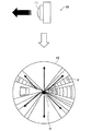
図2は、本開示の第1の実施形態においてカメラを鉛直方向に向けて撮像された撮像画像の例について説明するための図である。図2には、カメラ10を鉛直方向に向けて撮像された撮像画像15の例が示されている。カメラ10は、魚眼レンズ11を有し、魚眼レンズ11の光軸方向は略鉛直方向である。また、カメラ10は、略水平方向、すなわち魚眼レンズ11の光軸方向に対して垂直な方向に移動している。
FIG. 2 is a diagram for describing an example of a captured image that is captured with the camera directed in the vertical direction in the first embodiment of the present disclosure. FIG. 2 shows an example of a captured
この場合、撮像画像15では、周縁部に動きベクトルVの発生点Rおよび収束点Cの両方が現れる。魚眼レンズ11の光軸方向が略鉛直方向である場合、撮像画像15の中央部がカメラ10の上方にあたり、撮像画像15の周縁部がカメラ10の周囲にあたる。ここで、撮像画像15は、カメラ10の全周を含む全周画像である。この状態でカメラ10が略水平方向に移動すると、時間的に連続して撮像される撮像画像15では、周縁部のある点、すなわちカメラ10が向かっている方向に対応する点から発生した画像が、主に両側に分かれて周縁部を流れ、撮像画像15の中心に対して反対側にある周縁部の点、すなわちカメラ10が遠ざかっている方向に対応する点に収束する。このようにして、動きベクトルVには発生点Rと収束点Cとが現れる。この場合、撮像画像15における観察者の注視点は、カメラ10が向かっていく先、すなわち発生点Rであるものと推定されうる。
In this case, in the captured
上述のように、画像処理装置100の点検出部110は、このような発生点Rと収束点Cとを検出しうる。ここで、点検出部110は、発生点Rと収束点Cとの位置関係の規則性を利用して、検出の処理を効率化してもよい。例えば、発生点Rが撮像画像15の周縁部の第1の部分で発見された場合、収束点Cは撮像画像15の中心に対して第1の部分の反対側に位置する第2の部分に存在するはずである。そこで、点検出部110は、この第2の部分を優先的に、または第2の部分に限定して収束点Cを探索してもよい。逆に、収束点Cが撮像画像15の周縁部の第1の部分で発見された場合、発生点Rは撮像画像15の中心に対して第1の部分の反対側に位置する第2の部分に存在するはずである。そこで、点検出部110は、この第2の部分を優先的に、または第2の部分に限定して発生点Rを探索してもよい。
As described above, the
より具体的には、例えば、点検出部110は、撮像画像15の端から順に動きベクトルを解析して発生点Rまたは収束点Cを探索し、撮像画像15の周縁部で発生点Rまたは収束点Cが発見された場合には、その部分を第1の部分として、探索の対象を当該第1の部分に対応する第2の部分(撮像画像15の中心に対して反対側の部分)にジャンプさせてもよい。このように、点検出部110による動きベクトルの解析の実行回数を削減することによって、画像処理装置100全体としての処理負荷が軽減されうる。
More specifically, for example, the
なお、例えば魚眼レンズ11の光軸方向が鉛直方向に対してある程度以上傾いているような場合、撮像画像15の周縁部には発生点Rまたは収束点Cのいずれか一方だけが現れ、他方の点は撮像画像15の範囲から外れうる。この場合、上記の第1の部分で発生点Rまたは収束点Cが発見されたとしても、第2の部分でこれらと対になる収束点Cまたは発生点Rは発見されない。しかし、この場合、第2の部分以外に収束点Cまたは発生点Rが存在することもないと考えられるため、点検出部110は第2の部分で収束点Cまたは発生点Rが発見されなかったことをもって探索を終了してもよい。
For example, when the optical axis direction of the fish-
図3は、本開示の第1の実施形態においてカメラを水平方向に向けて撮像された撮像画像の第1の例について説明するための図である。図3には、カメラ10を水平方向に向けて撮像された撮像画像15の例が示されている。カメラ10は、魚眼レンズ11を有し、魚眼レンズ11の光軸方向は略水平方向である。また、カメラ10は、略水平方向に、魚眼レンズ11のある方を前にして移動している。
FIG. 3 is a diagram for describing a first example of a captured image that is captured with the camera directed in the horizontal direction in the first embodiment of the present disclosure. FIG. 3 shows an example of a captured
この場合、撮像画像15では、中央部に動きベクトルVの発生点Rだけが現れる。カメラ10が魚眼レンズ11のある方を前にして移動している場合、撮像画像15の中央部がカメラ10の前方にあたり、撮像画像15の周縁部がカメラ10の上下および左右にあたる。この状態でカメラ10が前方に移動すると、時間的に連続して撮像される撮像画像15では、中央部のある点、すなわちカメラ10が向かっている方向に対応する点から発生した画像が周縁部に向かって流れ、そのまま撮像画像15の端へと発散する。このようにして、動きベクトルVには発生点Rだけが現れる。この場合、撮像画像15における観察者の注視点が、カメラ10が向かっていく先、すなわち発生点Rであるものと推定されうる。
In this case, in the captured
図4は、本開示の第1の実施形態においてカメラを水平方向に向けて撮像された撮像画像の第2の例について説明するための図である。図4にも、カメラ10を水平方向に向けて撮像された撮像画像15の例が示されている。カメラ10は、魚眼レンズ11を有し、魚眼レンズ11の光軸方向は略水平方向である。また、カメラ10は、略水平方向に、魚眼レンズ11のある方を後ろにして移動している。
FIG. 4 is a diagram for describing a second example of a captured image that is captured with the camera oriented in the horizontal direction in the first embodiment of the present disclosure. FIG. 4 also shows an example of the captured
この場合、撮像画像15では、中央部に動きベクトルVの収束点Cだけが現れる。カメラ10が魚眼レンズ11のある方を後ろにして移動している場合、撮像画像15の中央部がカメラ10の後方にあたり、撮像画像15の周縁部がカメラ10の上下および左右にあたる。この状態でカメラ10が前方に移動すると、時間的に連続して撮像される撮像画像15では、撮像画像15の端から現れた画像が周縁部から中央部に向かって流れ、中央部のある点、すなわちカメラ10が遠ざかっている方向に対応する点に収束する。このようにして、動きベクトルVには収束点Cだけが現れる。この場合、撮像画像15における観察者の注視点が、カメラ10が遠ざかっていく元、すなわち収束点Cであるものと推定されうる。
In this case, in the captured
(1−3.移動方向の推定)
図5は、本開示の第1の実施形態における移動方向の推定を概念的に示すフローチャートである。本実施形態では、画像処理装置100の画像編集部114が、撮像画像の周縁部で動きベクトルの発生点が検出された場合に、発生点が撮像画像の中心に対して所定の向きに位置するように撮像画像を回転させうる。このような処理が、撮像画像が収束点から発生点に向かって移動しながら撮像された画像であるという推定に基づく処理ともいえることは、上述した通りである。このように、本開示のいくつかの実施形態では、撮像画像の移動方向の推定に基づく処理が実行されうる。図5では、そのような推定の一例が概念的に示されている。
(1-3. Estimation of moving direction)
FIG. 5 is a flowchart conceptually showing the estimation of the moving direction in the first embodiment of the present disclosure. In the present embodiment, when the
なお、以下で説明する撮像画像の移動方向の推定は、必ずしも画像処理装置100において明示的に実行されるとは限らない。つまり、画像処理装置100において実現される機能、または画像処理装置100において実行されるステップの中に、撮像画像の移動方向に推定は必ずしも含まれない。ただし、例えば上記の画像編集部114の処理のように、点検出部110による発生点または収束点の検出結果に基づいて実行される処理は、検出結果から推定される撮像画像の移動方向をふまえて設定された処理でありうる。
Note that estimation of the moving direction of the captured image described below is not always explicitly executed in the
図を参照すると、まず、画像取得部106が、撮像画像を取得する(ステップS101)。上記のように、ここで取得される撮像画像は、魚眼レンズを介して時間的に連続して撮像されたものである。次に、ベクトル算出部108が撮像画像における動きベクトルを算出する(ステップS103)。なお、図ではベクトル算出部108および点検出部110のシンプルな処理が示されているが、上記の説明で提示されたようなオプションを採用することも可能である。
Referring to the figure, first, the
ここで、点検出部110が動きベクトルの発生点または収束点を検出した結果、撮像画像に発生点および収束点の両方が存在した場合(ステップS105のYES)、撮像画像は、図2に示した例のように、収束点から発生点に向かって移動しながら撮像された画像であると推定される(ステップS107)。なお、上述のように、魚眼レンズの光軸方向が鉛直方向に対して傾いていたなどの理由で撮像画像の周縁部に発生点または収束点のいずれか一方だけが現れ、他方の点が撮像画像の範囲から外れた場合を考慮して、ステップS105の条件は「撮像画像の周縁部に発生点または収束点が存在する?」と読み替えられてもよい。この場合、ステップS107でいう収束点および発生点は、撮像画像の範囲から外れた点を含みうる。 Here, when both the generation point and the convergence point exist in the captured image as a result of detecting the motion vector generation point or the convergence point by the point detection unit 110 (YES in step S105), the captured image is shown in FIG. As in the example, it is estimated that the image is captured while moving from the convergence point toward the generation point (step S107). Note that, as described above, only the generation point or the convergence point appears at the periphery of the captured image because the optical axis direction of the fisheye lens is inclined with respect to the vertical direction, and the other point is the captured image. In consideration of the case where it is out of the range, the condition of step S105 may be read as “Is there a generation point or a convergence point in the periphery of the captured image?”. In this case, the convergence point and the generation point in step S107 can include points that are out of the range of the captured image.
一方、ステップS105でNOの場合、撮像画像に発生点が存在すれば(ステップS109のYES)、撮像画像は、図3に示した例のように、発生点に向かって、すなわち発生点に近づくように移動しながら撮像された画像であると推定される(ステップS111)。また、ステップS109でもNOの場合、撮像画像に収束点が存在すれば(ステップS113のYES)、撮像画像は、図4に示した例のように、収束点から遠ざかるように移動しながら撮像された画像であると推定される(ステップS115)。なお、図示していないが、ステップS115でもNOの場合、すなわち点検出部110が発生点も収束点も検出しなかった場合、撮像画像が移動せずに撮像された画像であると推定されてもよい。
On the other hand, in the case of NO in step S105, if a generation point exists in the captured image (YES in step S109), the captured image is directed toward the generation point, that is, close to the generation point, as in the example illustrated in FIG. Thus, it is estimated that the image is captured while moving (step S111). In the case of NO in step S109 as well, if there is a convergence point in the captured image (YES in step S113), the captured image is captured while moving away from the convergence point as in the example shown in FIG. (Step S115). Although not shown, if NO in step S115, that is, if the
以上で説明したような移動方向の推定を、上記で説明した第1の実施形態に当てはめると、以下のようになる。 When the estimation of the moving direction as described above is applied to the first embodiment described above, the following is obtained.
まず、撮像画像が、図2に示した例のように、収束点から発生点に向かって移動しながら撮像された画像であると推定される場合(ステップS107)、画像編集部114が、発生点が撮像画像の中心に対して所定の向きに位置するように撮像画像を回転させうる。これは、後述するように、魚眼レンズを鉛直方向に向けて移動させながら撮像された撮像画像は、進行方向が画像の中心に対して所定の向きに位置する方が観察しやすいためである。
First, when it is estimated that the captured image is an image captured while moving from the convergence point toward the generation point as in the example illustrated in FIG. 2 (step S107), the
一方、撮像画像が、図3および図4に示した例のように、発生点に向かって、または収束点から遠ざかって移動しながら撮像された画像であると推定される場合(ステップS111,S115)、画像編集部114は撮像画像を回転させない。これは、これらの例のような画像では、既に上下および左右が固定されており、回転させる必要がないためである。
On the other hand, when the captured image is estimated to be an image captured while moving toward the generation point or away from the convergence point as in the example illustrated in FIGS. 3 and 4 (steps S111 and S115). ), The
(1−4.撮像画像の回転の例)
図6および図7を参照して、上述した画像処理装置100の画像編集部114における撮像画像の回転のより具体的な例について、さらに説明する。なお、以下で例示する撮像画像は、いずれも、図2に示した例のように、収束点から発生点に向かって移動しながら撮像された画像であるものとする。
(1-4. Example of rotation of captured image)
With reference to FIGS. 6 and 7, a more specific example of rotation of the captured image in the
図6は、本開示の第1の実施形態における撮像画像の回転の第1の例について説明するための図である。図6では、動きベクトルVの発生点Rと収束点Cとが存在する撮像画像15が示されている。撮像画像15をそのまま観察した場合、画像は、左上にある発生点Rから右下にある収束点Cへと、主に撮像画像15の両側に分かれて流れていく。このような状態での画像の観察は、観察者に違和感を覚えさせることが多いことが、経験的に知られている。
FIG. 6 is a diagram for describing a first example of rotation of a captured image according to the first embodiment of the present disclosure. In FIG. 6, a captured
そこで、図示された例では、回転角度算出部112が発生点Rが撮像画像15の中心に対して下に位置するように回転角度を算出し、画像編集部114が算出された回転角度に従って撮像画像15を回転させる。回転後の撮像画像15は、撮像画像15rとして図示されている。撮像画像15rでは、画像が下にある発生点Rから上にある収束点Cへと流れていくため、観察者は違和感を覚えにくい。
Therefore, in the illustrated example, the rotation
魚眼レンズを介して撮像された撮像画像の向きによる観察者の違和感に対処するためには、車両などの移動手段にカメラを設置する際に向きを固定したり、カメラとは別のセンサなどによってカメラの向きを検出したりすることも考えられるが、上記のように撮像後に撮像画像を回転させることによって、撮像時のカメラの向きに関わらず、より自然に観察することが可能な撮像画像を提供することができる。 In order to cope with the viewer's uncomfortable feeling due to the orientation of the captured image taken through the fisheye lens, the orientation is fixed when the camera is installed on a moving means such as a vehicle, or the camera is used by a sensor other than the camera. Although it is possible to detect the orientation of the image, rotating the captured image after imaging as described above provides a captured image that can be observed more naturally regardless of the orientation of the camera at the time of imaging. can do.
図7は、本開示の第1の実施形態における撮像画像の回転の第2の例について説明するための図である。図7でも、図6と同様に動きベクトルVの発生点Rと収束点Cとが存在する撮像画像15が示されている。図示された例では、回転角度算出部112が発生点Rと収束点Cとを結ぶ方向が左右方向に一致するように回転角度を算出し、画像編集部114が算出された回転角度に従って撮像画像15を回転させる。回転後の撮像画像15rでは、画像が右にある発生点Rから左にある収束点Cへと流れていく。このような撮像画像15rの向きは、例えば、観察者の注目がカメラの向かっていく先、すなわち発生点Rよりも、流れていく画像そのものにある場合に好適でありうる。
FIG. 7 is a diagram for describing a second example of rotation of a captured image according to the first embodiment of the present disclosure. FIG. 7 also shows the captured
(2.第2の実施形態)
次に、図8および図9を参照して、本開示の第2の実施形態について説明する。本実施形態では、上記の第1の実施形態に係る画像処理装置100と同様の機能が、第1および第2の画像処理装置に分散して実現される。
(2. Second Embodiment)
Next, a second embodiment of the present disclosure will be described with reference to FIGS. 8 and 9. In the present embodiment, functions similar to those of the
図8は、本開示の第2の実施形態に係る第1の画像処理装置の概略的な機能構成を示すブロック図であり、図9は、本開示の第2の実施形態に係る第2の画像処理装置の概略的な機能構成を示すブロック図である。 FIG. 8 is a block diagram illustrating a schematic functional configuration of the first image processing apparatus according to the second embodiment of the present disclosure, and FIG. 9 illustrates a second configuration according to the second embodiment of the present disclosure. It is a block diagram which shows the schematic function structure of an image processing apparatus.
図8を参照すると、第1の画像処理装置200は、通信部102と、記憶部104と、画像取得部106と、ベクトル算出部108と、点検出部110と、記録制御部202とを含む。さらに、第1の画像処理装置200は、回転角度算出部112を含んでもよい。
Referring to FIG. 8, the first
本実施形態において、第1の画像処理装置200は、ネットワークを介して他の装置から撮像画像を取得し、取得された画像をメタ情報とともに記録する装置である。第1の画像処理装置200は、メタ情報が関連付けられた画像を第2の画像処理装置250にネットワークを介して送信する。
In the present embodiment, the first
図9を参照すると、第2の画像処理装置250は、通信部252と、記憶部254と、画像取得部256と、回転角度算出部258と、画像編集部114とを含む。さらに、第2の画像処理装置250は、表示制御部116と、表示部118とを含んでもよい。
Referring to FIG. 9, the second
本実施形態において、第2の画像処理装置250は、ネットワークを介して第1の画像処理装置200からメタ情報が関連付けられた画像を取得し、メタ情報に従って取得された画像を編集する装置である。第2の画像処理装置250は、編集された画像を他の装置にネットワークを介して送信してもよいし、記憶部に蓄積してもよいし、あるいは自ら表示してもよい。
In the present embodiment, the second
第1の画像処理装置200および第2の画像処理装置250は、例えば各種のPC、タブレット端末、携帯電話(スマートフォンを含む)、ゲーム機、またはメディアプレーヤなどの端末装置であってもよく、ネットワークを介して端末装置にサービスを提供するサーバであってもよい。第1の画像処理装置200および第2の画像処理装置250は、例えば後述する情報処理装置のハードウェア構成によって実現される。第1の画像処理装置200または第2の画像処理装置250がサーバである場合、装置の機能はネットワークで接続された複数の情報処理装置が協働することによって実現されてもよい。以下、それぞれの構成要素についてさらに説明する。なお、上記の第1の実施形態で説明されたものと同様の機能構成については、共通の符号を付することによって重複した説明を省略する。
The first
記録制御部202は、例えばCPUがメモリに格納されたプログラムに従って動作することによって実現され、点検出部110による発生点または収束点の検出結果に基づくメタ情報を撮像画像に関連付けて記録する。例えば、記録制御部202は、検出された発生点または収束点の撮像画像内での位置を記録してもよい。また、第1の画像処理装置200が回転角度算出部112を含む場合、記録制御部202は、回転角度算出部112によって算出された撮像画像の回転角度を記録してもよい。
The
通信部252は、例えば通信装置によって実現され、有線または無線の各種のネットワークを介して第1の画像処理装置200を含む他の装置と通信する。例えば、通信部252は、第1の画像処理装置200から撮像画像のデータをメタ情報とともに受信して記憶部254に格納する。また、例えば、通信部252は、第2の画像処理装置250において編集されて記憶部254に格納された画像のデータを他の装置に送信する。さらに、図示していないが、第2の画像処理装置250がサーバである場合、通信部252は、サービスの提供を受ける端末装置から送信された処理の依頼などのコマンドを受信して第2の画像処理装置250の各部に提供する。
The
記憶部254は、例えばストレージ装置および各種のメモリの組み合わせによって実現され、第2の画像処理装置250で用いられる各種のデータを一時的または永続的に格納する。例えば、記憶部254は、通信部252が第1の画像処理装置から受信した撮像画像のデータとメタ情報とを少なくとも一時的に格納し、必要に応じて画像取得部256または回転角度算出部258に提供する。また、例えば、記憶部254は、画像編集部114によって編集された画像のデータを少なくとも一時的に格納し、必要に応じて他の装置に送信するために通信部252に提供する。あるいは、記憶部254は、編集された画像のデータを表示のために表示制御部116に提供してもよい。
The
画像取得部256は、例えばCPUがメモリに格納されたプログラムに従って動作することによって実現され、記憶部254に格納された撮像画像のデータを取得する。ここで、画像取得部256によってデータが取得される撮像画像は、魚眼レンズを介して時間的に連続して撮像されたものである。これらの画像は、例えば動画像として一連のフレームを構成するものであってもよいし、独立して撮像された2枚以上の静止画であってもよい。
The
回転角度算出部258は、第1の画像処理装置200が回転角度算出部112を含まない場合に設けられうる。回転角度算出部258は、例えばCPUがメモリに格納されたプログラムに従って動作することによって実現され、撮像画像の周縁部で発生点が検出された場合に、発生点が撮像画像の中心に対して所定の向きに位置するような撮像画像の回転角度を算出する。本実施形態では点検出部110が第1の画像処理装置200に含まれるため、回転角度算出部258は、第1の画像処理装置200から撮像画像とともに提供されたメタ情報を記憶部254から読み出し、このメタ情報に基づいて発生点の撮像画像内での位置を特定する。
The rotation
(3.第3の実施形態)
次に、図10を参照して、本開示の第3の実施形態について説明する。本実施形態では、上記の第1の実施形態と同様の機能が、撮像を実行する撮像装置において実現される。つまり、本実施形態では、撮像装置が画像処理装置としても機能する。
(3. Third embodiment)
Next, a third embodiment of the present disclosure will be described with reference to FIG. In the present embodiment, the same function as in the first embodiment is realized in the imaging apparatus that performs imaging. That is, in this embodiment, the imaging device also functions as an image processing device.
図10は、本開示の第3の実施形態に係る撮像装置の概略的な機能構成を示すブロック図である。図10を参照すると、撮像装置300は、撮像部302と、画像取得部304と、記憶部104と、ベクトル算出部108と、点検出部110と、回転角度算出部112と、画像編集部114とを含む。撮像装置300は、さらに、通信部102を含んでもよい。また、撮像装置300は、さらに、表示制御部116と、表示部118とを含んでもよい。
FIG. 10 is a block diagram illustrating a schematic functional configuration of an imaging apparatus according to the third embodiment of the present disclosure. Referring to FIG. 10, the
本実施形態において、撮像装置300は、自ら撮像を実行して撮像画像を取得し、取得された画像を編集する装置である。撮像装置300は、編集された画像を他の装置にネットワークを介して送信してもよいし、記憶部に蓄積してもよいし、あるいは自ら表示してもよい。
In the present embodiment, the
撮像装置300は、例えばデジタルカメラのように撮像機能を主な機能とする端末装置であってもよく、タブレット端末、携帯電話(スマートフォンを含む)、またはゲーム機などのように付加的な機能として撮像機能を有する端末装置であってもよい。撮像装置300は、例えば後述する情報処理装置のハードウェア構成によって実現される。以下、それぞれの構成要素についてさらに説明する。なお、上記の第1の実施形態で説明されたものと同様の機能構成については、共通の符号を付することによって重複した説明を省略する。
The
撮像部302は、例えば、CMOS(Complementary Metal Oxide Semiconductor)などの撮像素子を有する撮像装置と、撮像素子によって生成されたRAWデータに対して階調や色調の調節、ノイズ低減処理、サイズ変換などの処理を実行した上で例えばJPEG(Joint Photographic Experts Group)など各種の形式の画像データを生成する画像処理回路とによって実現される。撮像部302は、撮像素子へのオブジェクト像の結像を制御するためのレンズとして魚眼レンズを含み、魚眼レンズを介して時間的に連続して撮像した撮像画像を画像取得部304に提供する。魚眼レンズは、例えばデジタルカメラの場合の交換式レンズや、その他の端末装置の場合のレンズアタッチメントなどのように、撮像部302に着脱可能に取り付けられてもよい。
The
画像取得部304は、例えばCPUがメモリに格納されたプログラムに従って動作することによって実現され、撮像部302が撮像した撮像画像のデータを取得する。ここで、画像取得部304によってデータが取得される撮像画像は、撮像部302の魚眼レンズを介して時間的に連続して撮像されたものである。これらの画像は、例えば動画像として一連のフレームを構成するものであってもよいし、独立して撮像された2枚以上の静止画であってもよい。
The
(4.第4の実施形態)
次に、図11および図12を参照して、本開示の第4の実施形態について説明する。本実施形態では、上記の第3の実施形態に係る撮像装置300と同様の機能が、撮像装置と画像処理装置とに分散して実現される。
(4. Fourth embodiment)
Next, a fourth embodiment of the present disclosure will be described with reference to FIGS. 11 and 12. In the present embodiment, functions similar to those of the
図11は、本開示の第4の実施形態に係る撮像装置の概略的な機能構成を示すブロック図であり、図12は、本開示の第4の実施形態に係る画像処理装置の概略的な機能構成を示すブロック図である。 FIG. 11 is a block diagram illustrating a schematic functional configuration of an imaging apparatus according to the fourth embodiment of the present disclosure. FIG. 12 illustrates a schematic configuration of the image processing apparatus according to the fourth embodiment of the present disclosure. It is a block diagram which shows a function structure.
図11を参照すると、撮像装置400は、撮像部402と、画像取得部304と、記憶部104と、ベクトル算出部108と、点検出部110と、記録制御部202とを含む。撮像装置400は、さらに、通信部102、または回転角度算出部112を含んでもよい。また、撮像装置400は、さらに、表示制御部116と、表示部118とを含んでもよい。
Referring to FIG. 11, the
本実施形態において、撮像装置400は、自ら撮像を実行して撮像画像を取得し、取得された画像をメタ情報とともに記録する装置である。撮像装置400は、メタ情報が関連付けられた画像を記憶部104に含まれるリムーバブル記録媒体を介して画像処理装置450に受け渡すか、通信部102からネットワークを介して画像処理装置450に送信する。
In the present embodiment, the
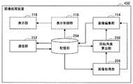
図12を参照すると、画像処理装置450は、通信部252と、記憶部254と、画像取得部256と、回転角度算出部258と、画像編集部114とを含む。さらに、画像処理装置450は、表示制御部116と、表示部118とを含んでもよい。なお、画像処理装置450の機能構成は、上記の第2の実施形態に係る第2の画像処理装置250の機能構成と同様である。
Referring to FIG. 12, the
本実施形態において、画像処理装置450は、ネットワークを介して撮像装置400からメタ情報が関連付けられた画像を取得し、メタ情報に従って取得された画像を編集する装置である。画像処理装置450は、編集された画像を他の装置にネットワークを介して送信してもよいし、記憶部に蓄積してもよいし、あるいは自ら表示してもよい。
In the present embodiment, the
撮像装置400は、例えばデジタルカメラのように撮像機能を主な機能とする端末装置であってもよく、タブレット端末、携帯電話(スマートフォンを含む)、またはゲーム機などのように付加的な機能として撮像機能を有する端末装置であってもよい。また、画像処理装置450は、例えば各種のPC、タブレット端末、携帯電話(スマートフォンを含む)、ゲーム機、またはメディアプレーヤなどの端末装置であってもよく、ネットワークを介して端末装置にサービスを提供するサーバであってもよい。撮像装置400および画像処理装置450は、例えば後述する情報処理装置のハードウェア構成によって実現される。画像処理装置450がサーバである場合、画像処理装置450の機能はネットワークで接続された複数の情報処理装置が協働することによって実現されてもよい。以下、それぞれの構成要素についてさらに説明する。なお、上記の第1〜第3の実施形態で説明されたものと同様の機能構成については、共通の符号を付することによって重複した説明を省略する。
The
撮像部402は、上記の第3の実施形態で説明した撮像部302と同様の機能構成であるが、撮像画像を画像取得部304に提供するだけではなく記憶部104に格納する。撮像装置400、記録制御部202によってメタ情報が撮像画像に関連付けて記録されるが、撮像画像の編集は撮像装置400ではなく画像処理装置450で実行されるため、記憶部104に格納される撮像画像は撮像部402から提供されたものでありうる。
The
(5.第5の実施形態)
次に、図13〜図15を参照して、本開示の第5の実施形態について説明する。本実施形態では、撮像装置において、撮像画像における動きベクトルの発生点または収束点の検出結果に基づいて撮像部が制御される。発生点または収束点の検出結果に基づく撮像画像の編集やメタ情報の記録は、必ずしも実行されなくてもよい。つまり、本実施形態は、発生点または収束点の検出結果を、撮像画像の編集などに用いる代わりに撮像部の制御に用いる例を含みうる。
(5. Fifth embodiment)
Next, a fifth embodiment of the present disclosure will be described with reference to FIGS. In the present embodiment, in the imaging apparatus, the imaging unit is controlled based on the detection result of the motion vector generation point or convergence point in the captured image. Editing of the captured image and recording of the meta information based on the detection result of the generation point or the convergence point are not necessarily executed. That is, this embodiment may include an example in which the detection result of the generation point or the convergence point is used for controlling the imaging unit instead of being used for editing the captured image.
(5−1.機能構成)
図13は、本開示の第5の実施形態に係る撮像装置の概略的な機能構成を示すブロック図である。図13を参照すると、撮像装置500は、撮像部402と、画像取得部304と、記憶部104と、ベクトル算出部108と、点検出部110と、撮像制御部502とを含む。撮像装置500は、さらに、回転角度算出部112と画像編集部114とを含んでもよく、通信部102を含んでもよく、表示制御部116と表示部118とを含んでもよい。また、図示していないが、撮像装置500は、上記の第2の実施形態で説明した記録制御部202を含んでもよい。
(5-1. Functional configuration)
FIG. 13 is a block diagram illustrating a schematic functional configuration of an imaging apparatus according to the fifth embodiment of the present disclosure. Referring to FIG. 13, the
撮像装置500は、例えばデジタルカメラのように撮像機能を主な機能とする端末装置であってもよく、タブレット端末、携帯電話(スマートフォンを含む)、またはゲーム機などのように付加的な機能として撮像機能を有する端末装置であってもよい。撮像装置500は、例えば後述する情報処理装置のハードウェア構成によって実現される。以下、それぞれの構成要素についてさらに説明する。なお、上記の第1〜第4の実施形態で説明されたものと同様の機能構成については、共通の符号を付することによって重複した説明を省略する。
The
撮像制御部502は、例えばCPUがメモリに格納されたプログラムに従って動作することによって実現され、点検出部110による発生点または収束点の検出結果に基づいて撮像部402を制御する。撮像制御部502は、例えば、撮像画像における発生点または収束点を含む領域の画像が最適化されるように撮像部402を制御しうる。撮像画像において発生点および収束点の両方が検出された場合、撮像制御部502は発生点を含む領域の画像がより最適化されるように撮像部402を制御してもよい。より具体的には、例えば、撮像制御部502は、発生点または収束点を含む領域を基準にして自動露出(AE:Automatic Exposure)、自動ホワイトバランス(AWB:Automatic White Balance)、またはオートフォーカス(AF:Autofocus)を設定するように撮像部402を制御してもよい。
The
(5−2.領域最適化の例)
図14および図15を参照して、上述した撮像装置500の撮像制御部502による撮像部402の制御のより具体的な例について、さらに説明する。
(5-2. Example of region optimization)
With reference to FIGS. 14 and 15, a more specific example of the control of the
図14は、本開示の第5の実施形態における撮像画像の領域最適化の第1の例について説明するための図である。図14では、動きベクトルVの発生点Rと収束点Cとが存在する撮像画像15が示されている。このような場合、撮像制御部502は、発生点Rを含む領域Aの画像が最適化されるように撮像部402を制御する。より具体的には、撮像制御部502は、領域Aを基準にしてAE、AWB、またはAFを設定するように撮像部402を制御しうる。
FIG. 14 is a diagram for describing a first example of area optimization of a captured image according to the fifth embodiment of the present disclosure. FIG. 14 shows a captured
上述のように、図示された例のような撮像画像15では、カメラが向かっていく先、すなわち発生点Rが観察者の注視点になるものと推定される。従って、発生点Rを含む領域Aの画像を最適化すると、観察者の体感上の最適化の効果がより大きくなる。
As described above, in the captured
図15は、本開示の第5の実施形態における撮像画像の領域最適化の第2の例について説明するための図である。図15では、動きベクトルVの収束点Cだけが存在する撮像画像15が示されている。このような場合、撮像制御部502は、収束点Cを含む領域Bの画像が最適化されるように撮像部402を制御する。より具体的には、撮像制御部502は、領域Bを基準にしてAE、AWB、またはAFを設定するように撮像部402を制御しうる。
FIG. 15 is a diagram for describing a second example of area optimization of a captured image according to the fifth embodiment of the present disclosure. FIG. 15 shows a captured
上述のように、図示された例のような撮像画像15では、カメラが遠ざかっていく元、すなわち収束点Cが観察者の注視点になるものと推定される。従って、収束点Cを含む領域Bの画像を最適化すると、観察者の体感上の最適化の効果がより大きくなる。
As described above, in the captured
なお、図示していないが、撮像制御部502は、動きベクトルの発生点だけが存在する撮像画像についても、同様に、発生点を含む領域の画像が最適化されるように撮像部402を制御しうる。
Although not shown, the
以上で説明した本開示の第5の実施形態では、例えば撮像画像の移動方向に応じて、観察者によって注視されると推定される点を含む領域で撮像画像が最適化される。従って、少なくとも観察者によって注視される領域では最適な画質が実現された、より見やすい撮像画像を提供することができる。 In the fifth embodiment of the present disclosure described above, the captured image is optimized in an area including a point estimated to be watched by the observer, for example, according to the moving direction of the captured image. Therefore, it is possible to provide an easy-to-view captured image in which optimum image quality is realized at least in an area watched by an observer.
(6.第6の実施形態)
次に、図16および図17を参照して、本開示の第6の実施形態について説明する。本実施形態では、撮像装置において、撮像画像における動きベクトルの発生点または収束点の検出結果に基づいて撮像画像の記録の実行および停止が制御される。発生点または収束点の検出結果に基づく撮像画像の編集やメタ情報の記録は、必ずしも実行されなくてもよい。つまり、本実施形態は、発生点または収束点の検出結果を、撮像画像の編集などに用いる代わりに撮像画像の記録の制御に用いる例を含みうる。
(6. Sixth embodiment)
Next, a sixth embodiment of the present disclosure will be described with reference to FIGS. 16 and 17. In the present embodiment, in the imaging apparatus, execution and stop of recording of the captured image are controlled based on the detection result of the motion vector generation point or convergence point in the captured image. Editing of the captured image and recording of the meta information based on the detection result of the generation point or the convergence point are not necessarily executed. That is, this embodiment may include an example in which the detection result of the generation point or the convergence point is used for controlling the recording of the captured image instead of being used for editing the captured image.
(6−1.機能構成)
図16は、本開示の第6の実施形態に係る撮像装置の概略的な機能構成を示すブロック図である。図16を参照すると、撮像装置600は、撮像部402と、画像取得部304と、記憶部104と、ベクトル算出部108と、点検出部110と、記録制御部602とを含む。撮像装置600は、さらに、回転角度算出部112を含んでもよく、通信部102を含んでもよく、表示制御部116と表示部118とを含んでもよく、撮像制御部502を含んでもよい。また、図示していないが、撮像装置600は、上記の第1の実施形態で説明した画像編集部114を含んでもよい。
(6-1. Functional configuration)
FIG. 16 is a block diagram illustrating a schematic functional configuration of an imaging apparatus according to the sixth embodiment of the present disclosure. Referring to FIG. 16, the
撮像装置600は、例えばデジタルカメラのように撮像機能を主な機能とする端末装置であってもよく、タブレット端末、携帯電話(スマートフォンを含む)、またはゲーム機などのように付加的な機能として撮像機能を有する端末装置であってもよい。撮像装置600は、例えば後述する情報処理装置のハードウェア構成によって実現される。以下、それぞれの構成要素についてさらに説明する。なお、上記の第1〜第5の実施形態で説明されたものと同様の機能構成については、共通の符号を付することによって重複した説明を省略する。
The
記録制御部602は、例えばCPUがメモリに格納されたプログラムに従って動作することによって実現され、点検出部110による発生点または収束点の検出結果に基づいて撮像画像の記録を制御する。記録制御部602は、例えば、撮像画像において発生点または収束点が検出されている場合に撮像画像の記録を実行し、発生点も収束点も検出されていない場合には撮像画像の記録を停止してもよい。あるいは、記録制御部602は、撮像画像において発生点または収束点が検出されている場合には撮像画像の記録を停止し、発生点も収束点も検出されていない場合に撮像画像の記録を実行してもよい。記録制御部602が撮像画像の記録を実行している間、撮像部402によって取得された撮像画像は記憶部104に記録される。また、記録制御部602が撮像画像の記録を停止している間、撮像部402によって取得された撮像画像は記憶部104には記録されない。
The
なお、記録制御部602は、上記の機能に加えて、上記の第2の実施形態で説明した記録制御部202と同様に、撮像画像にメタ情報を関連付けて記録する機能を有してもよい。また、撮像装置600が図示しない画像編集部114を含む場合、撮像部402から提供される撮像画像に代えて、画像編集部114によって編集された画像が記憶部104に記録されうる。
In addition to the above function, the
(6−2.記録制御の例)
図17は、本開示の第6の実施形態における記録制御の例を示すフローチャートである。図17を参照すると、まず、撮像装置600の画像取得部304が、撮像部402から撮像画像を取得する(ステップS201)。次に、ベクトル算出部108が撮像画像における動きベクトルを算出する(ステップS203)。なお、図ではベクトル算出部108および点検出部110のシンプルな処理が示されているが、上記の第1の実施形態などで説明されたようなオプションを採用することも可能である。
(6-2. Example of recording control)
FIG. 17 is a flowchart illustrating an example of recording control according to the sixth embodiment of the present disclosure. Referring to FIG. 17, first, the
ここで、点検出部110が動きベクトルの発生点または収束点を検出した結果、撮像画像に発生点または収束点の少なくともいずれかが存在した場合(ステップS205のYES)、記録制御部602は撮像画像の記録を実行/停止する(ステップS207)。一方、撮像画像に発生点も収束点も存在しなかった場合(ステップS205のNO)、記録制御部602は撮像画像の記録を停止/実行する(ステップS209)。なお、ステップS207で撮像画像の記録が実行される場合にはステップS209では撮像画像の記録が停止され、ステップS207で撮像画像の記録が停止される場合にはステップS209では撮像画像の記録が実行される。
Here, as a result of the
ここで、撮像画像において発生点または収束点が検出されている場合に撮像画像の記録が実行され、そうでない場合に撮像画像の記録が停止される例では、撮像装置600が移動している場合に限って撮像画像が記録されることになる。一方、撮像画像において発生点または収束点が検出されている場合に撮像画像の記録が停止され、そうでない場合に撮像画像の記録が実行される例では、撮像装置600が移動せずに停止している場合に限って撮像画像が記録されることになる。これらの例は、例えば撮像画像の用途などによって使い分けられうる。
Here, in the example in which the recording of the captured image is executed when the generation point or the convergence point is detected in the captured image, and in the example where the recording of the captured image is stopped otherwise, the
なお、以上で説明した第6の実施形態の変形例として、上記の第2の実施形態と同様の機能構成において、記録制御部202が、上記の記録制御部602と同様の機能を有してもよい。この場合、第1の画像処理装置200は、既に撮像された撮像画像から、カメラが移動している間、またはカメラが移動せずに停止している間に撮像された部分を抽出することになる。
As a modification of the sixth embodiment described above, the
(7.ハードウェア構成)
次に、図18を参照して、本開示の実施形態に係る情報処理装置のハードウェア構成について説明する。図18は、情報処理装置のハードウェア構成を説明するためのブロック図である。図示された情報処理装置900は、例えば、上記の実施形態における画像処理装置(第1の画像処理装置および第2の画像処理装置を含む)および撮像装置を実現しうる。
(7. Hardware configuration)
Next, the hardware configuration of the information processing apparatus according to the embodiment of the present disclosure will be described with reference to FIG. FIG. 18 is a block diagram for explaining a hardware configuration of the information processing apparatus. The illustrated
情報処理装置900は、CPU(Central Processing unit)901、ROM(Read Only Memory)903、およびRAM(Random Access Memory)905を含む。また、情報処理装置900は、ホストバス907、ブリッジ909、外部バス911、インターフェース913、入力装置915、出力装置917、ストレージ装置919、ドライブ921、接続ポート923、通信装置925を含んでもよい。さらに、情報処理装置900は、必要に応じて、撮像装置933、およびセンサ935を含んでもよい。情報処理装置900は、CPU901に代えて、またはこれとともに、DSP(Digital Signal Processor)またはASIC(Application Specific Integrated Circuit)と呼ばれるような処理回路を有してもよい。
The
CPU901は、演算処理装置および制御装置として機能し、ROM903、RAM905、ストレージ装置919、またはリムーバブル記録媒体927に記録された各種プログラムに従って、情報処理装置900内の動作全般またはその一部を制御する。ROM903は、CPU901が使用するプログラムや演算パラメータなどを記憶する。RAM905は、CPU901の実行において使用するプログラムや、その実行において適宜変化するパラメータなどを一次記憶する。CPU901、ROM903、およびRAM905は、CPUバスなどの内部バスにより構成されるホストバス907により相互に接続されている。さらに、ホストバス907は、ブリッジ909を介して、PCI(Peripheral Component Interconnect/Interface)バスなどの外部バス911に接続されている。
The
入力装置915は、例えば、マウス、キーボード、タッチパネル、ボタン、スイッチおよびレバーなど、ユーザによって操作される装置である。入力装置915は、例えば、赤外線やその他の電波を利用したリモートコントロール装置であってもよいし、情報処理装置900の操作に対応した携帯電話などの外部接続機器929であってもよい。入力装置915は、ユーザが入力した情報に基づいて入力信号を生成してCPU901に出力する入力制御回路を含む。ユーザは、この入力装置915を操作することによって、情報処理装置900に対して各種のデータを入力したり処理動作を指示したりする。
The
出力装置917は、取得した情報をユーザに対して視覚的または聴覚的に通知することが可能な装置で構成される。出力装置917は、例えば、LCD(Liquid Crystal Display)、PDP(Plasma Display Panel)、有機EL(Electro-Luminescence)ディスプレイなどの表示装置、スピーカおよびヘッドホンなどの音声出力装置、ならびにプリンタ装置などでありうる。出力装置917は、情報処理装置900の処理により得られた結果を、テキストまたは画像などの映像として出力したり、音声または音響などの音声として出力したりする。
The
ストレージ装置919は、情報処理装置900の記憶部の一例として構成されたデータ格納用の装置である。ストレージ装置919は、例えば、HDD(Hard Disk Drive)などの磁気記憶部デバイス、半導体記憶デバイス、光記憶デバイス、または光磁気記憶デバイスなどにより構成される。このストレージ装置919は、CPU901が実行するプログラムや各種データ、および外部から取得した各種のデータなどを格納する。
The
ドライブ921は、磁気ディスク、光ディスク、光磁気ディスク、または半導体メモリなどのリムーバブル記録媒体927のためのリーダライタであり、情報処理装置900に内蔵、あるいは外付けされる。ドライブ921は、装着されているリムーバブル記録媒体927に記録されている情報を読み出して、RAM905に出力する。また、ドライブ921は、装着されているリムーバブル記録媒体927に記録を書き込む。
The
接続ポート923は、機器を情報処理装置900に直接接続するためのポートである。接続ポート923は、例えば、USB(Universal Serial Bus)ポート、IEEE1394ポート、SCSI(Small Computer System Interface)ポートなどでありうる。また、接続ポート923は、RS−232Cポート、光オーディオ端子、HDMI(登録商標)(High-Definition Multimedia Interface)ポートなどであってもよい。接続ポート923に外部接続機器929を接続することで、情報処理装置900と外部接続機器929との間で各種のデータが交換されうる。
The
通信装置925は、例えば、通信ネットワーク931に接続するための通信デバイスなどで構成された通信インターフェースである。通信装置925は、例えば、有線または無線LAN(Local Area Network)、Bluetooth(登録商標)、またはWUSB(Wireless USB)用の通信カードなどでありうる。また、通信装置925は、光通信用のルータ、ADSL(Asymmetric Digital Subscriber Line)用のルータ、または、各種通信用のモデムなどであってもよい。通信装置925は、例えば、インターネットや他の通信機器との間で、TCP/IPなどの所定のプロトコルを用いて信号などを送受信する。また、通信装置925に接続される通信ネットワーク931は、有線または無線によって接続されたネットワークであり、例えば、インターネット、家庭内LAN、赤外線通信、ラジオ波通信または衛星通信などである。
The
撮像装置933は、例えば、CCD(Charge Coupled Device)またはCMOS(Complementary Metal Oxide Semiconductor)などの撮像素子、および撮像素子へのオブジェクト像の結像を制御するためのレンズなどの各種の部材を用いて実空間を撮像し、撮像画像を生成する装置である。撮像装置933は、静止画を撮像するものであってもよいし、また動画像を撮像するものであってもよい。
The
センサ935は、例えば、加速度センサ、ジャイロセンサ、地磁気センサ、光センサ、音センサなどの各種のセンサである。センサ935は、例えば情報処理装置900の筐体の姿勢など、情報処理装置900自体の状態に関する情報や、情報処理装置900の周辺の明るさや騒音など、情報処理装置900の周辺環境に関する情報を取得する。また、センサ935は、GPS(Global Positioning System)信号を受信して装置の緯度、経度および高度を測定するGPSセンサを含んでもよい。
The
以上、情報処理装置900のハードウェア構成の一例を示した。上記の各構成要素は、汎用的な部材を用いて構成されていてもよいし、各構成要素の機能に特化したハードウェアにより構成されていてもよい。かかる構成は、実施する時々の技術レベルに応じて適宜変更されうる。
Heretofore, an example of the hardware configuration of the
(8.補足)
本開示の実施形態は、例えば、上記で説明したような情報処理装置(画像処理装置(第1の画像処理装置および第2の画像処理装置を含む)または撮像装置)、複数の情報処理装置を含むシステム、情報処理装置またはシステムで実行される情報処理方法、情報処理装置を機能させるためのプログラム、およびプログラムが記録された一時的でない有形の媒体を含みうる。
(8. Supplement)
An embodiment of the present disclosure includes, for example, an information processing apparatus (an image processing apparatus (including a first image processing apparatus and a second image processing apparatus) or an imaging apparatus) as described above, and a plurality of information processing apparatuses. It may include a system, an information processing apparatus or an information processing method executed by the system, a program for causing the information processing apparatus to function, and a non-temporary tangible medium in which the program is recorded.
以上、添付図面を参照しながら本開示の好適な実施形態について詳細に説明したが、本開示の技術的範囲はかかる例に限定されない。本開示の技術分野における通常の知識を有する者であれば、請求の範囲に記載された技術的思想の範疇内において、各種の変形例または修正例に想到し得ることは明らかであり、これらについても、当然に本開示の技術的範囲に属するものと了解される。 The preferred embodiments of the present disclosure have been described in detail above with reference to the accompanying drawings, but the technical scope of the present disclosure is not limited to such examples. It is obvious that a person having ordinary knowledge in the technical field of the present disclosure can come up with various variations or modifications within the scope of the technical idea described in the claims. Of course, it is understood that it belongs to the technical scope of the present disclosure.
なお、以下のような構成も本開示の技術的範囲に属する。
(1)魚眼レンズを介して時間的に連続して撮像される撮像画像を取得する画像取得部と、
前記撮像画像における動きベクトルを取得するベクトル取得部と、
前記動きベクトルの発生点または収束点を検出する点検出部と
を備える画像処理装置。
(2)前記点検出部は、前記撮像画像の周縁部で前記発生点または前記収束点を検出する、前記(1)に記載の画像処理装置。
(3)前記点検出部は、前記発生点または前記収束点が前記撮像画像の第1の部分で発見された場合に、前記撮像画像の中心に対して前記第1の部分の反対側に位置する第2の部分で未発見の前記収束点または前記発生点を探索する、前記(2)に記載の画像処理装置。
(4)前記撮像画像が前記収束点から前記発生点に向かって移動しながら撮像された画像であるという推定に基づく処理を実行する処理部をさらに備える、前記(2)または(3)に記載の画像処理装置。
(5)前記点検出部は、前記撮像画像の中央部で前記発生点または前記収束点のいずれかを検出する、前記(1)に記載の画像処理装置。
(6)前記撮像画像が、前記発生点に近づくように移動しながら撮像された画像、または前記収束点から遠ざかるように移動しながら撮像された画像であるという推定に基づく処理を実行する処理部をさらに備える、前記(5)に記載の画像処理装置。
(7)前記点検出部は、前記動きベクトルの大きさまたは方向に基づいて設定される探索領域で前記発生点または前記収束点を探索する、前記(1)〜(6)のいずれか1項に記載の画像処理装置。
(8)前記点検出部は、前記動きベクトルの大きさが相対的に小さい領域を前記探索領域に設定する、前記(7)に記載の画像処理装置。
(9)前記点検出部は、相対的に多くの前記動きベクトルの方向が交差する領域を前記探索領域に設定する、前記(7)または(8)に記載の画像処理装置。
(10)前記点検出部は、前記撮像画像の全体について第1のブロックサイズで算出された動きベクトルに基づいて前記探索領域を設定し、
前記ベクトル取得部は、少なくとも前記探索領域について前記第1のブロックサイズよりも小さい第2のブロックサイズで前記動きベクトルを取得し、
前記点検出部は、前記第2のブロックサイズで算出された動きベクトルに基づいて前記探索領域で前記発生点または前記収束点を探索する、前記(7)〜(9)のいずれか1項に記載の画像処理装置。
(11)前記発生点または前記収束点の検出結果に基づいて前記撮像画像を編集する画像編集部をさらに備える、前記(1)〜(10)のいずれか1項に記載の画像処理装置。
(12)前記画像編集部は、前記撮像画像の周縁部で前記発生点が検出された場合に、前記発生点が前記撮像画像の中心に対して所定の向きに位置するように前記撮像画像を回転させる、前記(11)に記載の画像処理装置。
(13)前記画像編集部は、前記発生点が前記撮像画像の中心に対して下に位置するように前記撮像画像を回転させる、前記(12)に記載の画像処理装置。
(14)前記発生点または前記収束点の検出結果に基づく情報を前記撮像画像に関連付けて記録する記録制御部をさらに備える、前記(1)〜(10)のいずれか1項に記載の画像処理装置。
(15)前記発生点または前記収束点の検出結果に基づいて前記撮像画像を撮像する撮像部を制御する撮像制御部をさらに備える、前記(1)〜(14)のいずれか1項に記載の画像処理装置。
(16)前記撮像制御部は、前記発生点または前記収束点を含む領域の画像が最適化されるように前記撮像部を制御する、前記(15)に記載の画像処理装置。
(17)前記撮像制御部は、前記撮像画像で前記発生点および前記収束点の両方が検出された場合に、前記発生点を含む領域の画像がより最適化されるように前記撮像部を制御する、前記(16)に記載の画像処理装置。
(18)前記発生点または前記収束点の検出結果に基づいて前記撮像画像の記録を制御する記録制御部をさらに備える、前記(1)〜(17)のいずれか1項に記載の画像処理装置。
(19)魚眼レンズを介して時間的に連続して撮像される撮像画像を取得することと、
前記撮像画像における動きベクトルを取得することと、
プロセッサが、前記動きベクトルの発生点または収束点を検出することと
を含む画像処理方法。
(20)魚眼レンズを介して時間的に連続して撮像される撮像画像を取得する機能と、
前記撮像画像における動きベクトルを取得する機能と、
前記動きベクトルの発生点または収束点を検出する機能と
をコンピュータに実現させるためのプログラム。
The following configurations also belong to the technical scope of the present disclosure.
(1) an image acquisition unit that acquires captured images that are continuously captured in time via a fisheye lens;
A vector acquisition unit for acquiring a motion vector in the captured image;
An image processing apparatus comprising: a point detection unit that detects a generation point or a convergence point of the motion vector.
(2) The image processing apparatus according to (1), wherein the point detection unit detects the generation point or the convergence point at a peripheral portion of the captured image.
(3) The point detection unit is located on the opposite side of the first portion with respect to the center of the captured image when the generation point or the convergence point is found in the first portion of the captured image. The image processing apparatus according to (2), wherein the convergence point or the generation point that has not been found in the second part is searched.
(4) The method according to (2) or (3), further including a processing unit that executes processing based on an estimation that the captured image is an image captured while moving from the convergence point toward the generation point. Image processing apparatus.
(5) The image processing device according to (1), wherein the point detection unit detects either the generation point or the convergence point at a central portion of the captured image.
(6) A processing unit that performs processing based on an estimation that the captured image is an image captured while moving closer to the generation point or an image captured while moving away from the convergence point The image processing apparatus according to (5), further including:
(7) Any one of (1) to (6), wherein the point detection unit searches for the generation point or the convergence point in a search region set based on a magnitude or direction of the motion vector. An image processing apparatus according to 1.
(8) The image processing device according to (7), wherein the point detection unit sets an area in which the magnitude of the motion vector is relatively small as the search area.
(9) The image processing device according to (7) or (8), wherein the point detection unit sets, as the search region, a region where relatively many motion vector directions intersect.
(10) The point detection unit sets the search region based on a motion vector calculated with a first block size for the entire captured image,
The vector acquisition unit acquires the motion vector with a second block size smaller than the first block size for at least the search region,
In any one of (7) to (9), the point detection unit searches for the generation point or the convergence point in the search area based on a motion vector calculated with the second block size. The image processing apparatus described.
(11) The image processing apparatus according to any one of (1) to (10), further including an image editing unit that edits the captured image based on a detection result of the generation point or the convergence point.
(12) When the generation point is detected at a peripheral portion of the captured image, the image editing unit displays the captured image so that the generation point is positioned in a predetermined direction with respect to the center of the captured image. The image processing device according to (11), wherein the image processing device is rotated.
(13) The image processing device according to (12), wherein the image editing unit rotates the captured image so that the generation point is positioned below a center of the captured image.
(14) The image processing according to any one of (1) to (10), further including a recording control unit that records information based on a detection result of the generation point or the convergence point in association with the captured image. apparatus.
(15) The recording apparatus according to any one of (1) to (14), further including an imaging control unit that controls an imaging unit that captures the captured image based on a detection result of the generation point or the convergence point. Image processing device.
(16) The image processing device according to (15), wherein the imaging control unit controls the imaging unit so that an image of an area including the generation point or the convergence point is optimized.
(17) The imaging control unit controls the imaging unit so that an image of a region including the generation point is further optimized when both the generation point and the convergence point are detected in the captured image. The image processing apparatus according to (16).
(18) The image processing device according to any one of (1) to (17), further including a recording control unit that controls recording of the captured image based on a detection result of the generation point or the convergence point. .
(19) Acquiring captured images that are continuously captured in time via a fisheye lens;
Obtaining a motion vector in the captured image;
An image processing method, comprising: a processor detecting a generation point or a convergence point of the motion vector.
(20) a function of acquiring captured images that are continuously captured in time via a fisheye lens;
A function of acquiring a motion vector in the captured image;
A program for causing a computer to realize a function of detecting a generation point or a convergence point of the motion vector.
100,450 画像処理装置
102,252 通信部
104,254 記憶部
106,256,304 画像取得部
108 ベクトル算出部
110 点検出部
112,258 回転角度算出部
114 画像編集部
200 第1の画像処理装置
202,602 記録制御部
250 第2の画像処理装置
300,400,500,600 撮像装置
302,402 撮像部
502 撮像制御部
DESCRIPTION OF SYMBOLS 100,450 Image processing apparatus 102,252 Communication part 104,254 Storage part 106,256,304
Claims (16)
前記撮像画像における動きベクトルを取得するベクトル取得部と、
前記動きベクトルの発生点または収束点を検出する点検出部と
前記撮像画像の周縁部で前記発生点が検出された場合に、前記発生点が前記撮像画像の中心に対して所定の向きに位置するように前記撮像画像を回転させる画像編集部と、
を備える画像処理装置。 An image acquisition unit that acquires captured images that are continuously captured in time via a fisheye lens;
A vector acquisition unit for acquiring a motion vector in the captured image;
A point detection unit that detects a generation point or a convergence point of the motion vector; and the generation point is positioned in a predetermined direction with respect to a center of the captured image when the generation point is detected at a peripheral portion of the captured image. An image editing unit for rotating the captured image so as to
An image processing apparatus comprising:
前記ベクトル取得部は、少なくとも前記探索領域について前記第1のブロックサイズよりも小さい第2のブロックサイズで前記動きベクトルを取得し、
前記点検出部は、前記第2のブロックサイズで算出された動きベクトルに基づいて前記探索領域で前記発生点または前記収束点を探索する、請求項5に記載の画像処理装置。 The point detection unit sets the search region based on a motion vector calculated with a first block size for the entire captured image,
The vector acquisition unit acquires the motion vector with a second block size smaller than the first block size for at least the search region,
The image processing apparatus according to claim 5, wherein the point detection unit searches for the generation point or the convergence point in the search region based on a motion vector calculated with the second block size.
前記撮像画像における動きベクトルを取得することと、
プロセッサが、前記動きベクトルの発生点または収束点を検出することと、
前記撮像画像の周縁部で前記発生点が検出された場合に、前記発生点が前記撮像画像の中心に対して所定の向きに位置するように前記プロセッサが前記撮像画像を回転させることと、
を含む画像処理方法。 Obtaining captured images that are imaged continuously in time via a fisheye lens;
Obtaining a motion vector in the captured image;
A processor detects the origin or convergence point of the motion vector;
When the generation point is detected at a peripheral portion of the captured image, the processor rotates the captured image so that the generation point is positioned in a predetermined direction with respect to the center of the captured image;
An image processing method including:
前記撮像画像における動きベクトルを取得する機能と、
前記動きベクトルの発生点または収束点を検出する機能と
前記撮像画像の周縁部で前記発生点が検出された場合に、前記発生点が前記撮像画像の中心に対して所定の向きに位置するように前記撮像画像を回転させる機能と、
をコンピュータに実現させるためのプログラム。 A function of acquiring captured images that are continuously captured in time via a fisheye lens;
A function of acquiring a motion vector in the captured image;
A function of detecting a generation point or a convergence point of the motion vector; and when the generation point is detected at a peripheral portion of the captured image, the generation point is positioned in a predetermined direction with respect to the center of the captured image. A function of rotating the captured image;
A program to make a computer realize.
Priority Applications (1)
| Application Number | Priority Date | Filing Date | Title |
|---|---|---|---|
| JP2019150580A JP6897728B2 (en) | 2013-05-16 | 2019-08-20 | Image processing equipment, image processing methods and programs |
Applications Claiming Priority (2)
| Application Number | Priority Date | Filing Date | Title |
|---|---|---|---|
| JP2013103670 | 2013-05-16 | ||
| JP2013103670 | 2013-05-16 |
Related Parent Applications (1)
| Application Number | Title | Priority Date | Filing Date |
|---|---|---|---|
| JP2015516987A Division JP6398971B2 (en) | 2013-05-16 | 2014-03-28 | Image processing apparatus, image processing method, and program |
Related Child Applications (1)
| Application Number | Title | Priority Date | Filing Date |
|---|---|---|---|
| JP2019150580A Division JP6897728B2 (en) | 2013-05-16 | 2019-08-20 | Image processing equipment, image processing methods and programs |
Publications (2)
| Publication Number | Publication Date |
|---|---|
| JP2018195348A JP2018195348A (en) | 2018-12-06 |
| JP6575652B2 true JP6575652B2 (en) | 2019-09-18 |
Family
ID=51898153
Family Applications (4)
| Application Number | Title | Priority Date | Filing Date |
|---|---|---|---|
| JP2015516987A Expired - Fee Related JP6398971B2 (en) | 2013-05-16 | 2014-03-28 | Image processing apparatus, image processing method, and program |
| JP2018164355A Active JP6575652B2 (en) | 2013-05-16 | 2018-09-03 | Image processing apparatus, image processing method, and program |
| JP2019150580A Active JP6897728B2 (en) | 2013-05-16 | 2019-08-20 | Image processing equipment, image processing methods and programs |
| JP2021094217A Active JP7115593B2 (en) | 2013-05-16 | 2021-06-04 | Image processing device, image processing method and program |
Family Applications Before (1)
| Application Number | Title | Priority Date | Filing Date |
|---|---|---|---|
| JP2015516987A Expired - Fee Related JP6398971B2 (en) | 2013-05-16 | 2014-03-28 | Image processing apparatus, image processing method, and program |
Family Applications After (2)
| Application Number | Title | Priority Date | Filing Date |
|---|---|---|---|
| JP2019150580A Active JP6897728B2 (en) | 2013-05-16 | 2019-08-20 | Image processing equipment, image processing methods and programs |
| JP2021094217A Active JP7115593B2 (en) | 2013-05-16 | 2021-06-04 | Image processing device, image processing method and program |
Country Status (5)
| Country | Link |
|---|---|
| US (1) | US9800780B2 (en) |
| EP (1) | EP2998934B1 (en) |
| JP (4) | JP6398971B2 (en) |
| CN (1) | CN105190694B (en) |
| WO (1) | WO2014185169A1 (en) |
Families Citing this family (7)
| Publication number | Priority date | Publication date | Assignee | Title |
|---|---|---|---|---|
| JP2014225108A (en) * | 2013-05-16 | 2014-12-04 | ソニー株式会社 | Image processing apparatus, image processing method, and program |
| JP6623729B2 (en) * | 2015-12-04 | 2019-12-25 | 株式会社ソシオネクスト | Ranging systems, moving objects and parts |
| JP2017175965A (en) * | 2016-03-29 | 2017-10-05 | ソニー株式会社 | Image processing apparatus, image processing method, and image processing system |
| WO2018083984A1 (en) * | 2016-11-02 | 2018-05-11 | ソニー株式会社 | Information processing device, information processing method and information processing system |
| JP7192582B2 (en) * | 2019-03-11 | 2022-12-20 | オムロン株式会社 | Object tracking device and object tracking method |
| JP7380177B2 (en) | 2019-12-19 | 2023-11-15 | 株式会社Jvcケンウッド | Virtual reality image display system and control method for virtual reality image display system |
| US11412151B2 (en) * | 2020-04-02 | 2022-08-09 | Jvckenwood Corporation | Vehicle imaging device, image processing method, and image processing program |
Family Cites Families (35)
| Publication number | Priority date | Publication date | Assignee | Title |
|---|---|---|---|---|
| US5619593A (en) * | 1991-09-12 | 1997-04-08 | Fuji Photo Film Co., Ltd. | Method for extracting object images and method for detecting movements thereof |
| JP2863381B2 (en) * | 1992-09-25 | 1999-03-03 | 矢崎総業株式会社 | Vehicle monitoring method |
| JP3452268B2 (en) * | 1993-08-06 | 2003-09-29 | 矢崎総業株式会社 | Rear side monitoring method for vehicles |
| US6438254B1 (en) * | 1999-03-17 | 2002-08-20 | Matsushita Electric Industrial Co., Ltd. | Motion vector detection method, motion vector detection apparatus, and data storage media |
| DE60009114T2 (en) | 1999-09-20 | 2004-08-05 | Matsushita Electric Industrial Co. Ltd. | DEVICE FOR SUPPORTING VEHICLE DRIVERS |
| JP2001251632A (en) * | 1999-12-27 | 2001-09-14 | Toshiba Corp | Motion vector detection method and system, and motion vector detection program |
| JP2003299040A (en) * | 2002-04-03 | 2003-10-17 | Sony Corp | Motion vector detector and method |
| JP4355535B2 (en) * | 2003-08-07 | 2009-11-04 | 株式会社岩根研究所 | 360 degree image conversion processing device |
| JP4566591B2 (en) * | 2004-03-19 | 2010-10-20 | キヤノン株式会社 | Image deformation estimation method and image deformation estimation apparatus |
| JP2006059202A (en) * | 2004-08-20 | 2006-03-02 | Iwate Univ | Imaging device and image correction method |
| JP4502385B2 (en) * | 2004-11-30 | 2010-07-14 | キヤノン株式会社 | Image processing apparatus and control method thereof |
| JP4546291B2 (en) * | 2005-03-01 | 2010-09-15 | キヤノン株式会社 | Image processing apparatus and control method thereof |
| US8693540B2 (en) * | 2005-03-10 | 2014-04-08 | Qualcomm Incorporated | Method and apparatus of temporal error concealment for P-frame |
| JP2006270676A (en) * | 2005-03-25 | 2006-10-05 | Fujitsu Ltd | Panorama image generating program, panorama image generating apparatus, and panorama image generation method |
| JP2007030815A (en) * | 2005-07-29 | 2007-02-08 | Yazaki Corp | Drive recorder |
| JP4926822B2 (en) * | 2006-05-24 | 2012-05-09 | 株式会社岩根研究所 | Spring point reference CV region image pre-placement device |
| JP2008068675A (en) * | 2006-09-12 | 2008-03-27 | Auto Network Gijutsu Kenkyusho:Kk | Apparatus for visually confirming vehicle periphery |
| JP4433046B2 (en) * | 2007-12-26 | 2010-03-17 | 株式会社デンソー | Exposure control device and exposure control program |
| JP5105481B2 (en) | 2008-05-27 | 2012-12-26 | 国立大学法人鳥取大学 | Lane detection device, lane detection method, and lane detection program |
| JP2010021761A (en) * | 2008-07-10 | 2010-01-28 | Nippon Hoso Kyokai <Nhk> | Video image automatic recording control device |
| JP5155110B2 (en) * | 2008-11-17 | 2013-02-27 | 株式会社日立国際電気 | Monitoring device |
| US8248401B2 (en) * | 2009-03-19 | 2012-08-21 | International Business Machines Corporation | Accelerated data structure optimization based upon view orientation |
| GB2469679B (en) * | 2009-04-23 | 2012-05-02 | Imagination Tech Ltd | Object tracking using momentum and acceleration vectors in a motion estimation system |
| FR2947935B1 (en) * | 2009-07-08 | 2012-03-02 | Valeo Vision Sas | METHOD FOR DEFINING A SEARCH WINDOW |
| US8744216B2 (en) * | 2010-03-18 | 2014-06-03 | Panasonic Corporation | Omnidirectional image processing device and method using warp processing for enhanced object visibility |
| CN103004178B (en) * | 2010-06-30 | 2017-03-22 | 富士胶片株式会社 | Image capture device, program, and image capture method |
| DE102010042248A1 (en) | 2010-10-11 | 2012-04-12 | Robert Bosch Gmbh | Method and device for visualizing an environment of a vehicle |
| TW201218761A (en) * | 2010-10-27 | 2012-05-01 | Hon Hai Prec Ind Co Ltd | Image stabilization system and method |
| US20120113326A1 (en) * | 2010-11-04 | 2012-05-10 | Stmicroelectronics, Inc. | System and method for detecting motion vectors in a recursive hierarchical motion estimation system using a non-rasterized scan |
| JP5754214B2 (en) * | 2011-03-31 | 2015-07-29 | 富士通株式会社 | Image processing apparatus and image processing program |
| JP2012226645A (en) | 2011-04-21 | 2012-11-15 | Sony Corp | Image processing apparatus, image processing method, recording medium, and program |
| JP5864984B2 (en) | 2011-09-26 | 2016-02-17 | 東芝アルパイン・オートモティブテクノロジー株式会社 | In-vehicle camera image correction method and in-vehicle camera image correction program |
| JP2015039085A (en) * | 2011-12-14 | 2015-02-26 | パナソニック株式会社 | Image processor and image processing method |
| JP2013165485A (en) * | 2012-01-11 | 2013-08-22 | Panasonic Corp | Image processing apparatus, image capturing apparatus, and computer program |
| JP6141601B2 (en) * | 2012-05-15 | 2017-06-07 | 東芝アルパイン・オートモティブテクノロジー株式会社 | In-vehicle camera automatic calibration device |
-
2014
- 2014-03-28 JP JP2015516987A patent/JP6398971B2/en not_active Expired - Fee Related
- 2014-03-28 EP EP14797314.3A patent/EP2998934B1/en active Active
- 2014-03-28 US US14/888,191 patent/US9800780B2/en active Active
- 2014-03-28 CN CN201480026103.3A patent/CN105190694B/en active Active
- 2014-03-28 WO PCT/JP2014/059109 patent/WO2014185169A1/en active Application Filing
-
2018
- 2018-09-03 JP JP2018164355A patent/JP6575652B2/en active Active
-
2019
- 2019-08-20 JP JP2019150580A patent/JP6897728B2/en active Active
-
2021
- 2021-06-04 JP JP2021094217A patent/JP7115593B2/en active Active
Also Published As
| Publication number | Publication date |
|---|---|
| CN105190694A (en) | 2015-12-23 |
| JP6398971B2 (en) | 2018-10-03 |
| JP6897728B2 (en) | 2021-07-07 |
| US9800780B2 (en) | 2017-10-24 |
| JP2021141608A (en) | 2021-09-16 |
| EP2998934B1 (en) | 2020-08-05 |
| WO2014185169A1 (en) | 2014-11-20 |
| CN105190694B (en) | 2019-01-22 |
| JP2018195348A (en) | 2018-12-06 |
| EP2998934A4 (en) | 2016-10-26 |
| EP2998934A1 (en) | 2016-03-23 |
| JP2019200816A (en) | 2019-11-21 |
| US20160073020A1 (en) | 2016-03-10 |
| JP7115593B2 (en) | 2022-08-09 |
| JPWO2014185169A1 (en) | 2017-02-23 |
Similar Documents
| Publication | Publication Date | Title |
|---|---|---|
| JP6575652B2 (en) | Image processing apparatus, image processing method, and program | |
| US10410680B2 (en) | Automatic generation of video and directional audio from spherical content | |
| US9754159B2 (en) | Automatic generation of video from spherical content using location-based metadata | |
| WO2014185170A1 (en) | Image processing device, image processing method, and program | |
| US20190051019A1 (en) | Display control device, display control method, and program | |
| US9742995B2 (en) | Receiver-controlled panoramic view video share | |
| JP6459972B2 (en) | Display control apparatus, display control method, and program | |
| US20180103197A1 (en) | Automatic Generation of Video Using Location-Based Metadata Generated from Wireless Beacons | |
| JP6149862B2 (en) | Display control device, display control system, and display control method | |
| JPWO2017154411A1 (en) | IMAGING DEVICE, ELECTRONIC DEVICE, AND IMAGING SYSTEM | |
| JP7143359B2 (en) | Image processing device, image processing method, and program | |
| US20180012410A1 (en) | Display control method and device | |
| US20170171492A1 (en) | Display control apparatus, imaging apparatus, and display control method | |
| JPWO2015151548A1 (en) | Electronic equipment and recording medium | |
| Matsumoto et al. | Image processing device and method to obtain a 360 image without remapping | |
| WO2015198672A1 (en) | Information processing device, information processing method, and program | |
| WO2017086021A1 (en) | Image processing device, image processing method, and computer program |
Legal Events
| Date | Code | Title | Description |
|---|---|---|---|
| A621 | Written request for application examination |
Free format text: JAPANESE INTERMEDIATE CODE: A621 Effective date: 20180904 |
|
| RD04 | Notification of resignation of power of attorney |
Free format text: JAPANESE INTERMEDIATE CODE: A7424 Effective date: 20190208 |
|
| RD03 | Notification of appointment of power of attorney |
Free format text: JAPANESE INTERMEDIATE CODE: A7423 Effective date: 20190214 |
|
| RD04 | Notification of resignation of power of attorney |
Free format text: JAPANESE INTERMEDIATE CODE: A7424 Effective date: 20190222 |
|
| RD02 | Notification of acceptance of power of attorney |
Free format text: JAPANESE INTERMEDIATE CODE: A7422 Effective date: 20190515 |
|
| RD04 | Notification of resignation of power of attorney |
Free format text: JAPANESE INTERMEDIATE CODE: A7424 Effective date: 20190522 |
|
| A977 | Report on retrieval |
Free format text: JAPANESE INTERMEDIATE CODE: A971007 Effective date: 20190710 |
|
| TRDD | Decision of grant or rejection written | ||
| A01 | Written decision to grant a patent or to grant a registration (utility model) |
Free format text: JAPANESE INTERMEDIATE CODE: A01 Effective date: 20190723 |
|
| A61 | First payment of annual fees (during grant procedure) |
Free format text: JAPANESE INTERMEDIATE CODE: A61 Effective date: 20190805 |
|
| R151 | Written notification of patent or utility model registration |
Ref document number: 6575652 Country of ref document: JP Free format text: JAPANESE INTERMEDIATE CODE: R151 |