JP6575615B2 - Head-up display device and lighting unit thereof - Google Patents
Head-up display device and lighting unit thereof Download PDFInfo
- Publication number
- JP6575615B2 JP6575615B2 JP2018013729A JP2018013729A JP6575615B2 JP 6575615 B2 JP6575615 B2 JP 6575615B2 JP 2018013729 A JP2018013729 A JP 2018013729A JP 2018013729 A JP2018013729 A JP 2018013729A JP 6575615 B2 JP6575615 B2 JP 6575615B2
- Authority
- JP
- Japan
- Prior art keywords
- lens
- stage
- light
- display
- last
- Prior art date
- Legal status (The legal status is an assumption and is not a legal conclusion. Google has not performed a legal analysis and makes no representation as to the accuracy of the status listed.)
- Active
Links
Images


Landscapes
- Instrument Panels (AREA)
- Non-Portable Lighting Devices Or Systems Thereof (AREA)
Description
本発明は、ヘッドアップディスプレイ装置及びその照明ユニットに関する。 The present invention relates to a head-up display device and an illumination unit thereof.
従来、表示器により形成されて拡大光学系により拡大された表示像を移動体の表示部材に投影することにより、当該表示像の虚像を移動体室内のうち視認領域にて視認可能に表示するヘッドアップディスプレイ装置(以下、「HUD装置」という)は、広く知られている。 Conventionally, by projecting a display image formed by a display device and enlarged by a magnifying optical system onto a display member of a moving body, a head that displays a virtual image of the display image so as to be visible in a viewing area in the moving body chamber Up-display devices (hereinafter referred to as “HUD devices”) are widely known.
こうしたHUD装置において、表示器を透過照明して表示像の光を視認領域まで到達させる照明ユニットとしては、例えば特許文献1において開示される如き構造の照明ユニットがある。この照明ユニットには、光源からの放射光を表示器へ向かって集光する複数段の集光レンズとして、初段のコンデンサレンズ、中段のレンチキュラーレンズ及び最後段の集光レンズが設けられている。
In such a HUD device, an illumination unit having a structure as disclosed in, for example,
さて、特許文献1の照明ユニットでは、複数の光源に対して共通となる一つの凸レンズが、最後段の集光レンズとして用いられている。このように複数光源に対して共通化される最後段の集光レンズには、それら光源からの光を有効利用して表示器の広い面積を照明するために、大きな有効径を与えておく必要がある。一般に集光レンズでは、有効径が大きいと、レンズ面の曲率を大きくし難く、それ故に焦点距離を小さくし難い。そのため、最後段の集光レンズが複数光源に対して共通化される特許文献1の照明ユニットでは、全段の集光レンズを合成した合成レンズの焦点である合成焦点は、初段のコンデンサレンズから離間することになる。
Now, in the illumination unit of
ここで、特許文献1の照明ユニットの如き構造において、各光源からの光を視認領域に結像させて照明効率を高めるには、拡大光学系を挟んで視認領域と共役な共役位置に、それら各光源を配置する必要がある。そこで、本発明者が検討した結果、コンデンサレンズが光源との間にあける間隔を、同コンデンサレンズが合成焦点との間にあける間隔に応じた特定範囲に設定すれば、視認領域との共役位置に各光源を正確に配置可能となることが、判明した。しかし、さらなる鋭意検討の結果、特許文献1の照明ユニットの如き構造では、上述の如く合成焦点がコンデンサレンズから離間することに起因して、同コンデンサレンズ及び光源の間隔も広げなければならず、大型化することも判明した。
Here, in the structure such as the illumination unit of
本発明は、以上説明した知見に鑑みてなされたものであって、その目的は、HUD装置において表示器の広い面積を高い照明効率にて照明する小型の照明ユニット、並びにそうした照明ユニットを備えたHUD装置の提供にある。 The present invention has been made in view of the knowledge described above, and an object thereof is to provide a small illumination unit that illuminates a wide area of a display device with high illumination efficiency in a HUD device, and such an illumination unit. To provide a HUD device.
まず、開示された第一発明は、表示器(5)により形成されて拡大光学系(6)により拡大された表示像(10)を移動体(8)の表示部材(81)に投影することにより、当該表示像の虚像(10a)を移動体の室内のうち視認領域(91)にて視認可能に表示するHUD装置(1)において、表示器を透過照明して表示像の光を視認領域まで到達させる照明ユニット(2)であって、拡大光学系を挟んで視認領域と共役な共役位置(Pl)に配置されて光を放射する光源(20)と、光源からの光を表示器へ向かって集光する複数段の集光レンズ(21,2021)とを、一組の照明単位(26,2026)として、所定の基準方向(X)に並ぶ複数組の当該照明単位を、備え、各組の照明単位は、光源に最も近接して配置される集光レンズとしての初段レンズ(22)と、光源から最も離間して配置される集光レンズとしての最後段レンズ(24,2024)とを、少なくとも含み、各組の照明単位において、初段レンズから最後段レンズまで全段の集光レンズを合成した合成レンズの合成焦点(Pc)を、想定すると、各組の照明単位における初段レンズの頂点を含むように定義される主平面(224)は、光源との間にあける間隔(Gl)を、合成焦点との間にあける間隔(Gc)以下に設定され、各組の照明単位(2026)において、最後段レンズ(2024)は、第一光軸(Af1)を第二光軸(Af2)から基準方向に偏心させて定める仮想レンズ面として、同一組の照明単位における光源が第一光軸上に配置され且つ第一光軸を基準方向に挟んで線対称形となる第一仮想レンズ面(2240a)から、一部分ずつ抽出した形状に形成される複数の第一レンズ面部(2240)と、第二光軸を定める仮想レンズ面として、第二光軸を基準方向に挟んで線対称形となる第二仮想レンズ面(2241a)から、一部分ずつ抽出した形状に形成され、基準方向において第一レンズ面部と交互に配列される複数の第二レンズ面部(2241)とを、有することを特徴とする。 First, the disclosed first invention projects the display image (10) formed by the display (5) and enlarged by the magnifying optical system (6) onto the display member (81) of the moving body (8). Thus, in the HUD device (1) that displays the virtual image (10a) of the display image in a viewable area (91) in the room of the moving body so as to be visible, the display light is transmitted through the display and the light of the display image is displayed. An illumination unit (2) that reaches the light source, the light source (20) that is arranged at a conjugate position (Pl) conjugate with the visual recognition region with the magnifying optical system interposed therebetween, and the light from the light source to the display A plurality of condensing lenses (21, 2021) that condense toward each other as a set of illumination units (26, 2026), and a plurality of sets of the illumination units arranged in a predetermined reference direction (X), Each set of lighting units is a condensing level located closest to the light source. A first-stage lens (22) as a's, the last stage lens (24,2024) as a condensing lens disposed most apart from the light source, at least comprise, in each set of lighting units, or the first stage lens the combined focal synthetic lens obtained by combining all stages of the condenser lens to Luo top rear stage lens (Pc), assuming the main plane defined to include the apex of the first-stage lens in each set of lighting units (224) , distance to open between the light source (Gl), spacing (Gc) to open between the synthesis focal set below, in each set of lighting units (2026), the last stage lens (2024) is the As a virtual lens surface determined by decentering one optical axis (Af1) from the second optical axis (Af2) in the reference direction, the light sources in the same set of illumination units are arranged on the first optical axis and the first optical axis is the reference Axisymmetric with respect to the direction A plurality of first lens surface portions (2240) formed in a shape extracted partly from the first virtual lens surface (2240a) and a virtual lens surface defining the second optical axis, the second optical axis is sandwiched in the reference direction. A plurality of second lens surface portions (2241) formed in a shape extracted part by part from the second virtual lens surface (2241a) that is line-symmetrical at, and alternately arranged with the first lens surface portions in the reference direction, and wherein the Rukoto that Yusuke.
かかる第一発明によると、基準方向に並ぶ各組の照明単位は、拡大光学系を挟んで視認領域と共役な共役位置に配置される光源からの光を、それぞれ複数段の集光レンズにより表示器へと向かって集光する。こうした集光構造を各組の照明単位により実現する照明ユニットでは、光源に最近接の初段レンズ及び同光源から最離間の最後段レンズを少なくとも含んだいずれの段の集光レンズも、複数光源に同数ずつ対応して設けられることになる。故に、各組の照明単位によれば、全段の集光レンズの有効径及び焦点距離をそれぞれ小さくしながらも、表示器の広い面積を照明できる。 According to the first invention, each set of illumination units arranged in the reference direction displays the light from the light source arranged at the conjugate position conjugate with the visual recognition area with the magnifying optical system sandwiched by the plurality of condensing lenses, respectively. Condensed toward the vessel. In an illumination unit that realizes such a condensing structure with each set of illumination units, any stage of condensing lens including at least the first stage lens closest to the light source and the last stage lens furthest away from the light source can be used as a plurality of light sources. The same number is provided correspondingly. Therefore, according to each set of illumination units, it is possible to illuminate a wide area of the display, while reducing the effective diameter and focal length of the condenser lenses in all stages.
しかも、各組の照明単位における初段レンズの頂点を含むように定義される主平面が光源との間にあける間隔は、いずれも小さな焦点距離の集光レンズを合成した合成レンズの合成焦点との間に、同主平面があける間隔以下となる。これによれば、初段レンズ主平面及び合成焦点の間隔が小さくなるのに応じて、同主平面及び光源の間隔も小さくなる。故に、照明ユニットの体格を小型化しながらも、各光源からの光を視認領域に結像させて照明効率を高めることができる。 Moreover, the combined focal distance, the synthetic lens both synthesized condenser lens of a small focal length of opening between the main plane light source that is defined to include the apex of your Keru stage lens in the illumination unit of each set Is less than or equal to the interval between the main planes. According to this, as the distance between the first-stage lens main plane and the composite focal point decreases, the distance between the main plane and the light source also decreases. Therefore, while reducing the size of the illumination unit, the light from each light source can be imaged in the viewing area to increase the illumination efficiency.
次に、開示された第二発明は、表示器(5)により形成されて拡大光学系(6)により拡大された表示像(10)を移動体(8)の表示部材(81)に投影することにより、当該表示像の虚像(10a)を移動体の室内のうち視認領域(91)にて視認可能に表示するHUD装置(1)であって、第一発明の照明ユニット(2)と共に、表示器及び拡大光学系が設けられることを特徴とする。 Next, the disclosed second invention projects the display image (10) formed by the display (5) and enlarged by the magnifying optical system (6) onto the display member (81) of the moving body (8). By this, it is a HUD device (1) which displays the virtual image (10a) of the display image so that it can be visually recognized in the visual recognition area (91) in the room of the moving object, together with the illumination unit (2) of the first invention, A display and a magnifying optical system are provided.
かかる第二発明のHUD装置では、第一発明の特徴を少なくとも有した小型の照明ユニットにより、表示器の広い面積を高い照明効率にて透過照明できるので、移動体での配置自由度と共に、当該照明効率に応じた虚像の輝度も確保し得るのである。 In such a HUD device of the second invention, a small illumination unit having at least the features of the first invention can transmit and illuminate a wide area of the display device with high illumination efficiency. The brightness of the virtual image according to the illumination efficiency can be ensured.
以下、本発明の複数の実施形態を図面に基づいて説明する。尚、各実施形態において対応する構成要素には同一の符号を付すことにより、重複する説明を省略する場合がある。各実施形態において構成の一部分のみを説明している場合、当該構成の他の部分については、先行して説明した他の実施形態の構成を適用することができる。また、各実施形態の説明において明示している構成の組み合わせばかりではなく、特に組み合わせに支障が生じなければ、明示していなくても複数の実施形態の構成同士を部分的に組み合せることができる。 Hereinafter, a plurality of embodiments of the present invention will be described with reference to the drawings. In addition, the overlapping description may be abbreviate | omitted by attaching | subjecting the same code | symbol to the corresponding component in each embodiment. When only a part of the configuration is described in each embodiment, the configuration of the other embodiment described above can be applied to the other part of the configuration. In addition, not only combinations of configurations explicitly described in the description of each embodiment, but also the configurations of a plurality of embodiments can be partially combined even if they are not explicitly specified unless there is a problem with the combination. .
(第一実施形態)
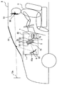
図1に示すように、本発明の第一実施形態によるHUD装置1は、「移動体」としての車両8に搭載されて、インストルメントパネル80内に収容されている。HUD装置1は、車両8の「表示部材」であるウインドシールド81へ表示像10を投影する。その結果、車両8の室内では、ウインドシールド81により反射した表示像10の光が視認者9のアイポイント90に到達する。視認者9は、アイポイント90への到達光を知覚することにより、ウインドシールド81の前方に表示像10の虚像10aを視認する。このとき虚像10aの視認は、アイポイント90が車両8の室内のうち視認領域91に位置する場合に、限られる。換言すれば、アイポイント90が視認領域91から外れている場合には、視認者9による虚像10aの視認が困難となる。
(First embodiment)
As shown in FIG. 1, the
HUD装置1には、照明ユニット2と共に、表示器5、拡大光学系6及び表示制御ユニット7が設けられている。
In addition to the
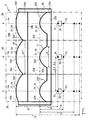
照明ユニット2は、一つの光源20及び複数段の集光レンズ21を一組の照明単位26として、図2,3に示すように、複数組の照明単位26を備えている。ここで、本実施形態において三組の照明単位26は、それぞれ二段ずつ設けられる集光レンズ21として、同一組の光源20に最も近接して配置の初段レンズ22と、同一組の光源20から最も離間して配置の最後段レンズ24とを、含んでいる。したがって、照明ユニット2において光源20と初段レンズ22と最後段レンズ24とは、互いに同数となる三つずつ、それぞれ設けられている。
The
各組の照明単位(以下、「各組照明単位」と略記する)26をなす光源20はそれぞれ、例えば発光ダイオード(LED)等の点状発光源からなり、拡大光学系6を挟んで視認領域91と共役な共役位置Pl(図1参照)に配置される。各組照明単位26において光源20は、通電に従って発光することにより、例えば白色等の光を放射する。
Each of the
各組照明単位26をなす初段レンズ22同士は、例えば樹脂又はガラス等の透光性材料により一体形成されることにより、全体として長方形板状の初段レンズアレイ22aを構成している。各組照明単位26において初段レンズ22は、同一組の集光レンズ21の中で最大の正パワーを与えられた初段レンズ面220を有することにより、同一組の光源20から放射された光の一部を集光する。
The first-
各組照明単位26をなす最後段レンズ24同士は、例えば樹脂又はガラス等の透光性材料により一体形成されることにより、全体として長方形板状の最後段レンズアレイ24aを構成している。各組照明単位26において最後段レンズ24は、同一組の初段レンズ22よりも小さな正パワーを与えられた最後段レンズ面240を有することにより、当該初段レンズ22を通した光源20からの光を集光する。かかる集光機能により、各組照明単位26の光源20からの光は、図1に示す表示器5及び拡大光学系6を経て、視認領域91に結像される。このとき各組照明単位26の最後段レンズ24は、同一組の光源20からの光に対して、視認領域91での結像位置を調整することになる。
The last-stage lenses 24 constituting each
表示器5は、例えばドットマトリクス型TFT液晶パネル等の画像表示パネルであり、最後段レンズアレイ24a(図2参照)に対応した長方形の画面50を有している。表示器5は、画面50を構成する複数画素の駆動により、表示像10としてのモノクロ画像又はカラー画像を当該画面50上に形成する。表示器5において画面50は、最後段レンズ24により集光した光を各組照明単位26から受けることにより、透過照明される。ここで画面50では、各組照明単位26からの光による照明対象エリアが互いにずらされることにより、当該画面50の全域という広い面積に対しての照明が可能となっている。こうした照明を受けて表示器5は、画面50上の表示像10を発光表示させる。尚、表示像10は、例えば車両8の走行速度や進行方向、ウォーニング等の車両関連情報を表示する光像として、発光表示される。
The
拡大光学系6は、単一の凹面鏡60を主体として、構成されている。凹面鏡60は、例えば樹脂又はガラス等の基材にアルミニウム等の金属反射膜を蒸着させてなり、反射面60aを形成している。凹面鏡60は、表示器5の画面50から入射する光を反射面60aにより反射する反射機能を有しており、当該機能により反射させた光をウインドシールド81側へと導光する。かかる導光によりウインドシールド81には、画面50上の表示像10が拡大して投影されることにより、車両8の室内のうち視認領域91では、視認者9により視認可能に当該表示像10の虚像10aが表示される。したがって、視認領域91は、凹面鏡60の仕様及び姿勢によって決まる領域となる。尚、凹面鏡60の姿勢については、可変とすることにより視認領域91の移動を許容してもよいし、固定とすることにより視認領域91の位置を不変としてもよい。また、拡大光学系6としては、複数の凹面鏡60を有するものであってもよいし、凹面鏡60以外の反射鏡又はレンズを有するものであってもよい。
The magnifying
表示制御ユニット7は、例えばマイクロコンピュータ等の電子回路であり、各組照明単位26の光源20と表示器5とに電気接続されている。さらに表示制御ユニット7は、車両8のうち例えば他の制御ユニット及び各種センサ等と通信可能に接続されている。表示制御ユニット7は、各組照明単位26の光源20に対する通電を車両関連情報に応じて制御することにより、それらの光源20を発光させる。それと共に表示制御ユニット7は、画面50の構成画素の駆動を車両関連情報に応じて制御することにより、画面50上での表示像10の表示、ひいては視認者9への虚像10aの表示を実現する。
The display control unit 7 is an electronic circuit such as a microcomputer, for example, and is electrically connected to the
(照明ユニットの詳細構成)
次に、第一実施形態による各組照明単位26の構造を、さらに詳細に説明する。
(Detailed configuration of lighting unit)
Next, the structure of each
図2,3に示すように各組照明単位26は、所定の基準方向Xに並んでいる。ここで基準方向Xは、画面50(図1参照)の長手方向に対応した各レンズアレイ22a,24aの長手方向と実質一致している。また、基準方向Xに対する直交方向Yは、画面50の短手方向に対応した各レンズアレイ22a,24aの短手方向と実質一致している。
As shown in FIGS. 2 and 3, each
各組照明単位26の光源20は、基準方向Xに互いに離間して並んでいる。各組照明単位26をなす光源20同士では、基準方向Xにおける中心間距離としてのピッチΔsが一定値に設定されている。
The
図3に示すように、初段レンズアレイ22aにおいて入射面22bは、各組照明単位26の光源20と所定距離をあけて対向するように、平面状に形成されている。初段レンズアレイ22aにおいて出射面22cは、各組照明単位26の初段レンズ22を構成するように基準方向Xに並んだ初段レンズ面220を、それぞれ形成している。このように、各組照明単位26の初段レンズ面220が同一組の光源20に対して反対側の出射面22cに形成されることにより、当該光源20からの光に対して収差の低減が可能となっている。
As shown in FIG. 3, in the first
各組照明単位26の初段レンズ面220がそれぞれ個別に定める光軸Ac上には、同一組の光源20が配置されている。これにより、初段レンズ面220をそれぞれ有して基準方向Xに並ぶ各組照明単位26の初段レンズ22同士では、当該方向Xにおける光軸間距離Δaが光源20同士のピッチΔsと一致している。また、各組照明単位26において初段レンズ面220の主平面224は、光軸Ac上の頂点を含むように、定義される。これにより各組照明単位26では、初段レンズ22がその光軸Acに沿った一定の間隔Glを、主平面224と光源20との間に確保している。
The same set of
各組照明単位26の初段レンズ面220は、本実施形態では、シリンドリカル型(図2参照)の凸レンズ面状に形成されている。これにより各組照明単位26の初段レンズ面220は、互いに同一のレンズプロファイルとして、それぞれの定める光軸Acを基準方向Xに挟んで線対称形となるプロファイルを、有している。それと共に各組照明単位26の初段レンズ面220は、基準方向Xに沿う縦断面では、それぞれの定める光軸Acを挟んだ両側にて少なくとも一階微分且つ二階微分が可能となるように、所定の有効径φi及び曲率Ciを有している。こうした初段レンズ面220の有効径φi及び曲率Ciに応じて各組照明単位26では、初段レンズ22の焦点距離fiが正の値に設定されている。尚、初段レンズ面220については、二階微分まで可能であってもよいし、三階以上の階数での微分まで可能であってもよい。
In the present embodiment, the
最後段レンズアレイ24aは、レンズフレーム28を介して初段レンズアレイ22aと組み合わされている。最後段レンズアレイ24aにおいて入射面24bは、初段レンズアレイ22aの出射面22cと所定距離をあけて対向するように、平面状に形成されている。これにより各組照明単位26同士では、最後段レンズアレイ24a及び初段レンズアレイ22aのそれぞれ形成する最後段レンズ24及び初段レンズ22の間にて、主平面間距離Dが一定値に設定されている。ここで主平面間距離Dとは、最後段レンズ24の主平面244と初段レンズ22の主平面224との間の距離である。最後段レンズアレイ24aにおいて出射面24cは、各組照明単位26の最後段レンズ24を構成するように基準方向Xに並んだ最後段レンズ面240を、それぞれ形成している。
The
各組照明単位26の最後段レンズ面240がそれぞれ個別に定める光軸Acは、同一組における初段レンズ面220の光軸Acと一致している。即ち各組照明単位26では、初段レンズ22から最後段レンズ24まで全段の集光レンズ21に共通となる光軸Ac上に、光源20が配置されている。また、各組照明単位26において最後段レンズ面240の主平面244は、光軸Ac上の頂点を含むように、定義される。これにより各組照明単位26では、最後段レンズ24がその光軸Acに沿った一定の主平面間距離Dを、主平面244,224間に確保している。
The optical axis Ac individually defined by the last-
各組照明単位26の最後段レンズ面240は、本実施形態では、シリンドリカル型(図2参照)の凸レンズ面状に形成されている。これにより各組照明単位26の最後段レンズ面240は、互いに同一のレンズプロファイルとして、それぞれの定める光軸Acを基準方向Xに挟んで線対称形となるプロファイルを、有している。それと共に各組照明単位26の最後段レンズ面240は、基準方向Xに沿う縦断面では、それぞれの定める光軸Acを挟んだ両側にて少なくとも一階微分且つ二階微分が可能となるように、所定の有効径φf及び曲率Cfを有している。尚、最後段レンズ面240については、二階微分まで可能であってもよいし、三階以上の階数での微分まで可能であってもよい。
In the present embodiment, the last-
ここで、各組照明単位26において最後段レンズ面240の有効径φfは、初段レンズ面220の有効径φiよりも大きく設定されている。それと共に、各組照明単位26において最後段レンズ面240の曲率Cfは、初段レンズ面220の曲率Ciよりも小さく設定されている。こうした最後段レンズ面240の有効径φf及び曲率Cfにより各組照明単位26では、初段レンズ22よりも小さな正パワーが最後段レンズ24に与えられるため、当該初段レンズ22の正パワーが最大となっている。また、最後段レンズ面240の有効径φf及び曲率Cfに応じて各組照明単位26では、初段レンズ22の焦点距離fiよりも大きな正の値に、最後段レンズ24の焦点距離ffが設定されている。
Here, in each
以上の各組照明単位26において、初段レンズ22から最後段レンズ24まで全段の集光レンズ21を合成した合成レンズの焦点として、合成焦点Pcを想定する。かかる想定下、初段レンズ22の主平面224が光軸Acに沿って合成焦点Pcとの間にあける間隔Gcは、式1により表される。ここで各組照明単位26では、式1の右辺は0より大きい必要があることから、式2が成立している。さらに各組照明単位26では、先述の拡大光学系6を挟んだ視認領域91との共役位置Plに光源20を位置合わせさせるため、式2の成立下、式1により表される間隔Gcを用いた式3が成立している。即ち各組照明単位26では、初段レンズ22の主平面224が光源20との間にあける間隔Glは、同主平面224が合成焦点Pcとの間にあける間隔Gc以下に、設定されているのである。
Gc=(ff−D)/{1+(ff−D)/fi} …(式1)
ff−D>0 …(式2)
Gl≦Gc …(式3)
In each
Gc = (ff−D) / {1+ (ff−D) / fi} (Expression 1)
ff−D> 0 (Formula 2)
Gl ≦ Gc (Formula 3)
(作用効果)
ここまで説明した第一実施形態の作用効果を、以下に説明する。
(Function and effect)
The operational effects of the first embodiment described so far will be described below.
第一実施形態によると、基準方向Xに並ぶ各組照明単位26は、拡大光学系6を挟んで視認領域91と共役な共役位置Plに配置される光源20からの光を、それぞれ複数段の集光レンズ21により表示器5へと向かって集光する。こうした集光構造を各組照明単位26により実現する照明ユニット2では、光源20に最近接の初段レンズ22及び同光源20から最離間の最後段レンズ24を含んだいずれの段の集光レンズ21も、複数光源20に同数ずつ対応して設けられることになる。故に、各組照明単位26によれば、全段の集光レンズ21の有効径φi,φf及び焦点距離fi,ffをそれぞれ小さくしながらも、表示器5の広い面積を照明できる。
According to the first embodiment, each set of
しかも、各組照明単位26において初段レンズ22の主平面224が光源20との間にあける間隔Glは、いずれも小さな焦点距離fi,ffの集光レンズ21を合成した合成レンズの合成焦点Pcとの間に、同主平面224があける間隔Gc以下となる。これによれば、主平面224及び合成焦点Pcの間隔Gcが小さくなるのに応じて、主平面224及び光源20の間隔Glも小さくなる。故に、照明ユニット2の体格を小型化しながらも、各光源20からの光を視認領域91に結像させて照明効率を高めることができる。
Moreover, in each
したがって、第一実施形態のHUD装置1では、以上の如き特徴を有した小型の照明ユニット2により、表示器5の広い面積を高い照明効率にて照明できるので、車両8での配置自由度と共に、当該照明効率に応じた虚像10aの輝度も確保し得る。
Therefore, in the
また、第一実施形態による各組照明単位26において、正パワーが最大の集光レンズ21となる初段レンズ22は、最近接の光源20から放射された光のうち可及的に多くの光を、後段の集光レンズ21となる最後段レンズ24へと確実に集光できる。これによれば、各組照明単位26により表示器5へ集光される光量が確保されるので、照明効率を高め得る。
In each
さらに第一実施形態によると、各組照明単位26に二段ずつ設けられる集光レンズ21のうち初段レンズ22は、最近接光源20からの放射光のうち可及的に多くの光を、最大の正パワーにより確実に集光できる。また、各組照明単位26に二段ずつ設けられる集光レンズ21のうち最後段レンズ24は、初段レンズ22を通した光源20からの光に対する集光機能により当該光の結像位置を調整して、当該光の結像位置が視認領域91からずれる事態を抑制できる。これらによれば、各組照明単位26の構造を簡素にしながらも、高い照明効率の達成に大きく貢献し得る。
Furthermore, according to the first embodiment, the
加えて、第一実施形態において各組照明単位26の初段レンズ22同士及び最後段レンズ24同士は、互いに組み合わされる初段レンズアレイ22a及び最後段レンズアレイ24aを、それぞれ構成している。このような初段レンズアレイ22a及び最後段レンズアレイ24aによれば、初段レンズ22及び最後段レンズ24の主平面間距離Dは、それらアレイ組み合わせ時に互いにずれ難い。故に各組照明単位26では、初段レンズ22の主平面224及び光源20の間隔Glについて、アレイ組み合わせ後の主平面間距離Dに応じて決まる同主平面224及び合成焦点Pcの間隔Gcに対し、正確に調整し易くなる。これによれば、主平面224及び光源20の間隔Glが主平面224及び合成焦点Pcの間隔Gcよりも大きくなって、光源20からの光の結像位置が視認領域91からずれる事態を、抑制し得る。
In addition, in the first embodiment, the first-
また加えて、初段レンズ22から最後段レンズ24まで全段の集光レンズ21に共通の光軸Ac上に光源20が配置される第一実施形態の各組照明単位26によると、最後段レンズ24から出射される光の表示器5への入射角度は、ばらつき難くなる。これによれば、表示器5のうち各組照明単位26による照明対象エリア間に生じる照明ムラを、低減し得る。
In addition, according to each
(第二実施形態)
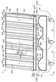
図4〜6に示すように本発明の第二実施形態は、第一実施形態の変形例である。第二実施形態による各組照明単位2026の二段の集光レンズ2021のうち、初段レンズ22よりも後段側の最後段レンズ2024は、第一レンズ面部2240と第二レンズ面部2241とを交互に複数ずつ配列してなる最後段レンズ面2242を、有している。
(Second embodiment)
As shown in FIGS. 4-6, 2nd embodiment of this invention is a modification of 1st embodiment. Of the two-
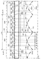
図6に示すように各組照明単位2026の第一レンズ面部2240は、複数の第一仮想レンズ面2240aの想定下、それぞれ対応する一つの第一仮想レンズ面2240aから一部分ずつを同図の破線の如く断続的に抽出した形状となるように、形成されている。尚、図6では、照明単位2026と同数となる三つの第一仮想レンズ面2240aのうち二つを、代表して示している。
As shown in FIG. 6, the first
ここで各第一仮想レンズ面2240aは、それぞれ個別に対応するいずれかの光軸Acを第一光軸Af1として定めるように、仮想的に規定されている。また、第二実施形態において各第一仮想レンズ面2240aは、シリンドリカル型の凸レンズ面状に規定されている。これにより各第一仮想レンズ面2240aは、互いに同一のレンズプロファイルとして、それぞれの定める第一光軸Af1を基準方向Xに挟んで線対称形となるプロファイルを、有している。それと共に各第一仮想レンズ面2240aは、基準方向Xに沿う縦断面では、互いに並ぶ第一光軸Af1と第二光軸Af2(後に詳述)との間にて少なくとも一階微分且つ二階微分が可能となるように、所定の有効径φf1及び曲率Cf1を有している。尚、各第一仮想レンズ面2240aについては、二階微分まで可能であってもよいし、三階以上の階数での微分まで可能であってもよい。
Here, each of the first
各組照明単位2026の第二レンズ面部2241は、複数の第二仮想レンズ面2241aの想定下、それぞれ対応する二つの第二仮想レンズ面2241aから一部分ずつを図6の破線の如く断続的に抽出した形状となるように、形成されている。尚、図6では、照明単位2026よりも一つ多い四つの第二仮想レンズ面2241aのうち三つを、代表して示している。
The second
ここで各第二仮想レンズ面2241aは、基準方向Xにおける第一光軸Af1,Af1間の中央位置に第二光軸Af2を定めるように、仮想的に規定されている。これより、基準方向Xにおいて互いに光軸間距離Δaをあけて平行にのびる各第二光軸Af2は、当該方向Xの両側をのびる第一光軸Af1,Af1に対して、それぞれ当該距離Δaの半値分ずつ離間している。即ち各第二光軸Af2は、基準方向Xにおいて両側の第一光軸Af1,Af1から、光軸間距離Δaの半値をあけて偏心している。
Here, each second
また、第二実施形態において各第二仮想レンズ面2241aは、シリンドリカル型の凸レンズ面状に規定されている。これにより各第二仮想レンズ面2241aは、互いに同一のレンズプロファイルとして、それぞれの定める第二光軸Af2を基準方向Xに挟んで線対称形となるプロファイルを、有している。それと共に各第二仮想レンズ面2241aは、基準方向Xに沿う縦断面では、互いに並ぶ第一光軸Af1と第二光軸Af2との間にて少なくとも一階微分且つ二階微分が可能となるように、所定の有効径φf2及び曲率Cf2を有している。尚、各第二仮想レンズ面2241aについても、二階微分まで可能であってもよいし、三階以上の階数での微分まで可能であってもよい。
In the second embodiment, each second
さらに、第二実施形態において各第二仮想レンズ面2241aは、各第一仮想レンズ面2240aと同一のレンズプロファイルを有している。これにより、各第二仮想レンズ面2241aの有効径φf2は、初段レンズ面220の有効径φiよりも大きい範囲にて、各第一仮想レンズ面2240aの有効径φf1と等しく設定されている。それと共に、各第二仮想レンズ面2241aの曲率Cf2は、初段レンズ面220の曲率Ciよりも小さい範囲にて、各第一仮想レンズ面2240aの曲率Cf1と等しく設定されている。
Furthermore, in the second embodiment, each second
図4〜6に示すように各組照明単位2026では、以上の如き第二仮想レンズ面2241aからの第二レンズ面部2241の抽出数は、先述した第一仮想レンズ面2240aからの第一レンズ面部2240の抽出数に対して、同数となる六つ又八つに設定されている。また図6に示すように、各組照明単位2026の基準方向Xにおいて、第一仮想レンズ面2240aからの第一レンズ面部2240の抽出幅W1は、第一光軸Af1に近い第一レンズ面部2240ほど広くなっている。一方、各組照明単位2026の基準方向Xにおいて、第二仮想レンズ面2241aからの第二レンズ面部2241の抽出幅W2は、第二光軸Af2に近い第二レンズ面部2241ほど広くなっている。
As shown in FIGS. 4 to 6, in each
さらに図5,6に示すように、各組照明単位2026の第一光軸Af1上では、第一レンズ面部2240同士が線対称に隣接している。一方、各組照明単位2026を両側に分けている第二光軸Af2上では、第二レンズ面部2241同士が線対称に隣接している。
5 and 6, on the first optical axis Af1 of each
以上の如き最後段レンズ2024を備える各組照明単位2026では、上述した各仮想レンズ面2240a,2241aの設定により、初段レンズ22よりも小さな正パワーが最後段レンズ2024に与えられている。故に第二実施形態においても、同一組の集光レンズ2021の中で初段レンズ22の正パワーが最大となっている。また、各仮想レンズ面2240a,2241aの設定により各組照明単位2026では、初段レンズ22の焦点距離fiより大きな正の値となるよう、第一仮想レンズ面2240aの焦点距離が図5の如き最後段レンズ2024の焦点距離ffとして設定されている。
In each
このような各組照明単位2026において、初段レンズ22から最後段レンズ2024まで全段の集光レンズ2021を合成した合成レンズの合成焦点Pcに対して、初段レンズ22の主平面224があける間隔Gcは、第一実施形態と同様、式1により表される。また、各組照明単位2026では、第一実施形態と同様、式2,3が成立していることにより、初段レンズ22の光軸Acに沿う方向にて、主平面224及び光源20の間隔Gcが主平面224及び合成焦点Pcの間隔Gc以下となっている。したがって、こうした第二実施形態によると、第一実施形態と同様の作用効果の発揮が可能である。
In each
加えて、第二実施形態によると、各組照明単位2026の最後段レンズ2024は、少なくとも二階微分の可能な第一仮想レンズ面2240aから一部分ずつ抽出した形状の第一レンズ面部2240を、複数有する。故に各組照明単位2026では、第一仮想レンズ面2240aの定める第一光軸Af1としての光軸Ac上に配置された光源20から、初段レンズ22を通過した光に対して、各第一レンズ面部2240による集光機能を発揮できる。
In addition, according to the second embodiment, the
また加えて、第二実施形態によると、各組照明単位2026の最後段レンズ2024は、少なくとも一階微分の可能な第二仮想レンズ面2241aから一部分ずつ抽出した形状の第二レンズ面部2241として、基準方向Xに第一レンズ面部2240と交互に配列されるレンズ面部を、複数有する。故に各組照明単位2026では、第一光軸Af1から基準方向Xに偏心して第二仮想レンズ面2241aの定める第二光軸Af2上と、同方向Xに並ぶ光軸Af1,Af2間とにて、第二レンズ面部2241からの出射光を第一レンズ面部2240からの出射光に重畳できる。こうした光の重畳機能によれば、各組照明単位2026において光源20の配置される光軸Acとしての第一光軸Af1上から離間する箇所にあっても、出射光の強度が高められることになる。したがって、表示器5のうち各組照明単位2026による照明対象エリアのそれぞれに生じる照明ムラを、低減し得る。
In addition, according to the second embodiment, the
さらに加えて、第二実施形態によると、仮想レンズ面2240a,2241aから部分抽出したレンズ面部2240,2241を配列してなる各最後段レンズ2024の採用により、それらレンズ2024を可及的に薄く形成できる。これによれば、初段レンズ22及び最後段レンズ2024の主平面間距離Dを小さくして、当該距離Dに応じて決まる間隔Gc以下の間隔Glも小さく設定し得る。故に、照明ユニット2の小型化においては特に有利となる。
In addition, according to the second embodiment, the
(他の実施形態)
以上、本発明の複数の実施形態について説明したが、本発明は、それらの実施形態に限定して解釈されるものではなく、本発明の要旨を逸脱しない範囲内において種々の実施形態及び組み合わせに適用することができる。
(Other embodiments)
Although a plurality of embodiments of the present invention have been described above, the present invention is not construed as being limited to these embodiments, and various embodiments and combinations can be made without departing from the scope of the present invention. Can be applied.
具体的に、第一及び第二実施形態に関する変形例1では、初段レンズアレイ22aの出射面22cに代えて又は加えて、同アレイ22aの入射面22bに初段レンズ面220を形成してもよい。ここで、出射面22c及び入射面22bにそれぞれ初段レンズ面220を形成する場合、それら各面22c,22bにて異ならせた基準方向毎に光源20を複数ずつ並べることにより、二次元配列構造を構築してもよい。
Specifically, in
第一及び第二実施形態に関する変形例2では、最後段レンズアレイ24aの出射面24cに代えて又は加えて、同アレイ24aの入射面24bに最後段レンズ面240,2242を形成してもよい。ここで、出射面24c及び入射面24bにそれぞれ最後段レンズ面240,2242を形成する場合、それら各面24c,24bにて異ならせた基準方向毎に光源20を複数ずつ並べることにより、二次元配列構造を構築してもよい。
In the second modification regarding the first and second embodiments, the last lens surfaces 240 and 2242 may be formed on the
第一及び第二実施形態に関する変形例3では、各組照明単位26,2026の集光レンズ21,2021については、初段レンズ22及び最後段レンズ24,2024を少なくとも含んでいれば、三段以上設けてもよい。例えば変形例3では、集光レンズ21としての中段レンズを初段レンズ22と最後段レンズ24,2024との間に配置し、それら全段の合成焦点と初段レンズ22の主平面224との間隔Gc以下に、光源20と同主平面224との間隔Glを設定してもよい。尚、この場合も、各組照明単位26,2026の中段レンズを、中段レンズアレイとして一体形成してもよい。
In the third modification related to the first and second embodiments, the condensing
第一及び第二実施形態に関する変形例4では、同一組の中で初段レンズ22よりも後段側の集光レンズ21(例えば最後段レンズ24,2024)に、最大の正パワーを与えてもよい。また、第一及び第二実施形態に関する変形例5では、各組照明単位26,2026において初段レンズ22及び最後段レンズ24,2024を含む全段の集光レンズ21のうち、少なくとも一段の集光レンズ21を、互いに別体に形成してもよい。
In Modification 4 regarding the first and second embodiments, the maximum positive power may be given to the condenser lens 21 (for example, the last-stage lenses 24 and 2024) on the rear stage side of the first-
第一及び第二実施形態に関する変形例6では、いずれかの組の照明単位26,2026において、光源20と共に、初段レンズ22よりも後段側の集光レンズ21(例えば最後段レンズ24,2024)を、初段レンズ22の光軸Ac(第二実施形態では第一光軸Af1)から偏心させてもよい。例えば、図7に示す第一実施形態の変形例6では、表示器5(図示しない)の画角中心の周辺を通過する周辺主光線Rs上に全段の集光レンズ21の頂点が配置された複数組の照明単位26において、光源20を、初段レンズ22の光軸Acから基準方向Xに偏心させて当該周辺主光線Rs上に配置している。但し、図7に示す第一実施形態の変形例6では、表示器5(図示しない)の画角中心を通過する中心主光線Rc上に全段の集光レンズ21の頂点が配置された一組の照明単位26においてのみ、光源20を、初段レンズ22の光軸Acと位置合わせして当該中心主光線Rc上に配置している。
In the modified example 6 related to the first and second embodiments, the condensing lens 21 (for example, the last stage lenses 24 and 2024) on the rear stage side with respect to the
第二実施形態に関する変形例7では、第一仮想レンズ面2240aのレンズプロファイルと第二仮想レンズ面2241aのレンズプロファイルとを、相異ならせてもよい。例えば変形例7では、第一仮想レンズ面2240aの曲率Cf1と第二仮想レンズ面2241aの曲率Cf2とを相異ならせてもよい。あるいは、図8に示す変形例7のように、第一仮想レンズ面2240aとは相異なるレンズプロファイルとして、基準方向Xに対して山形に傾斜することにより、基準方向Xに沿う縦断面の光軸Af1,Af2間にて一階微分までが可能なプリズムレンズ面状に、第二仮想レンズ面2241aを形成してもよい。
In Modification Example 7 related to the second embodiment, the lens profile of the first
第一及び第二実施形態に関する変形例8では、車両8の「表示部材」として、ウインドシールド81以外の要素、例えばウインドシールド81の室内側の面に貼りつけた又はウインドシールド81とは別体に形成されたコンバイナ等を、採用してもよい。また、第一及び第二実施形態に関する変形例9では、車両8以外の船舶乃至は飛行機等の「移動体」に搭載されるHUD装置1の照明ユニット2に、本発明を適用してもよい。
In the modified example 8 related to the first and second embodiments, as a “display member” of the
1 HUD装置、2 照明ユニット、5 表示器、6 拡大光学系、8 車両、10 表示像、10a 虚像、20 光源、21,2021 集光レンズ、22 初段レンズ、22a 初段レンズアレイ、24,2024 最後段レンズ、24a,2024a 最後段レンズアレイ、26,2026 照明単位、81 ウインドシールド、91 視認領域、224,244 主平面、2240 第一レンズ面部、2240a 第一仮想レンズ面、2241 第二レンズ面部、2241a 第二仮想レンズ面、Ac 光軸、Af1 第一光軸、Af2 第二光軸、ff,fi 焦点距離、Gc,Gl 間隔、Pc 合成焦点、Pl 共役位置、X 基準方向 1 HUD device, 2 lighting unit, 5 display, 6 magnification optical system, 8 vehicle, 10 display image, 10a virtual image, 20 light source, 21,2021 condenser lens, 22 first stage lens, 22a first stage lens array, 24, 2024 last Step lens, 24a, 2024a Last lens array, 26, 2026 Illumination unit, 81 Windshield, 91 Viewing area, 224, 244 Main plane, 2240 First lens surface, 2240a First virtual lens surface, 2241 Second lens surface, 2241a Second virtual lens surface, Ac optical axis, Af1 first optical axis, Af2 second optical axis, ff, fi focal length, Gc, Gl interval, Pc composite focal point, Pl conjugate position, X reference direction
Claims (7)
前記拡大光学系を挟んで前記視認領域と共役な共役位置(Pl)に配置されて光を放射する光源(20)と、前記光源からの光を前記表示器へ向かって集光する複数段の集光レンズ(21,2021)とを、一組の照明単位(26,2026)として、所定の基準方向(X)に並ぶ複数組の当該照明単位を、備え、
各組の前記照明単位は、前記光源に最も近接して配置される前記集光レンズとしての初段レンズ(22)と、前記光源から最も離間して配置される前記集光レンズとしての最後段レンズ(24,2024)とを、少なくとも含み、
各組の前記照明単位において、前記初段レンズから前記最後段レンズまで全段の前記集光レンズを合成した合成レンズの合成焦点(Pc)を、想定すると、各組の前記照明単位における前記初段レンズの頂点を含むように定義される主平面(224)は、前記光源との間にあける間隔(Gl)を、前記合成焦点との間にあける間隔(Gc)以下に設定され、
各組の前記照明単位(2026)において、前記最後段レンズ(2024)は、
第一光軸(Af1)を第二光軸(Af2)から前記基準方向に偏心させて定める仮想レンズ面として、同一組の前記照明単位における前記光源が前記第一光軸上に配置され且つ前記第一光軸を前記基準方向に挟んで線対称形となる第一仮想レンズ面(2240a)から、一部分ずつ抽出した形状に形成される複数の第一レンズ面部(2240)と、
前記第二光軸を定める仮想レンズ面として、前記第二光軸を前記基準方向に挟んで線対称形となる第二仮想レンズ面(2241a)から、一部分ずつ抽出した形状に形成され、前記基準方向において前記第一レンズ面部と交互に配列される複数の第二レンズ面部(2241)とを、有することを特徴とするヘッドアップディスプレイ装置の照明ユニット。 By projecting the display image (10) formed by the display (5) and enlarged by the magnification optical system (6) onto the display member (81) of the moving body (8), a virtual image (10a) of the display image is displayed. In a head-up display device (1) that displays a visible light in a visual recognition area (91) in the room of the mobile body, the illumination is transmitted through the display to allow the light of the display image to reach the visual recognition area. Unit (2),
A light source (20) that is arranged at a conjugate position (Pl) conjugate with the visual recognition region with the magnifying optical system interposed therebetween, and a plurality of stages for condensing light from the light source toward the display The condenser lens (21, 2021) is used as a set of illumination units (26, 2026), and includes a plurality of sets of the illumination units arranged in a predetermined reference direction (X).
The illumination unit of each set includes a first-stage lens (22) as the condensing lens arranged closest to the light source and a last-stage lens as the condensing lens arranged farthest from the light source. (24, 2024) at least,
Assuming a combined focal point (Pc) of a synthetic lens obtained by synthesizing the condenser lenses of all stages from the first stage lens to the last stage lens in each group of the illumination units, the first stage lens in each group of the illumination units is assumed. The main plane (224) defined so as to include the vertices is set so that the gap (Gl) between the light source and the light source is equal to or less than the gap (Gc) between the synthetic focal points ,
In each set of the illumination units (2026), the last lens (2024) is:
The light source in the same set of the illumination units is disposed on the first optical axis as a virtual lens surface that is determined by decentering the first optical axis (Af1) from the second optical axis (Af2) in the reference direction, and A plurality of first lens surface portions (2240) formed in a shape extracted part by part from a first virtual lens surface (2240a) having a line symmetry with the first optical axis sandwiched in the reference direction;
The virtual lens surface defining the second optical axis is formed in a shape extracted part by part from a second virtual lens surface (2241a) that is line-symmetric with the second optical axis in the reference direction, and the reference An illumination unit for a head-up display device, comprising a plurality of second lens surface portions (2241) arranged alternately with the first lens surface portions in a direction.
請求項1〜6のいずれか一項に記載の照明ユニット(2)と共に、前記表示器及び前記拡大光学系が設けられることを特徴とするヘッドアップディスプレイ装置。 By projecting the display image (10) formed by the display (5) and enlarged by the magnification optical system (6) onto the display member (81) of the moving body (8), a virtual image (10a) of the display image is displayed. Is a head-up display device (1) that displays in a visual recognition area (91) in the room of the mobile body,
A head-up display device, wherein the display unit and the magnifying optical system are provided together with the illumination unit (2) according to any one of claims 1 to 6 .
Priority Applications (1)
| Application Number | Priority Date | Filing Date | Title |
|---|---|---|---|
| JP2018013729A JP6575615B2 (en) | 2018-01-30 | 2018-01-30 | Head-up display device and lighting unit thereof |
Applications Claiming Priority (1)
| Application Number | Priority Date | Filing Date | Title |
|---|---|---|---|
| JP2018013729A JP6575615B2 (en) | 2018-01-30 | 2018-01-30 | Head-up display device and lighting unit thereof |
Related Parent Applications (1)
| Application Number | Title | Priority Date | Filing Date |
|---|---|---|---|
| JP2014118741A Division JP6369148B2 (en) | 2014-06-09 | 2014-06-09 | Head-up display device and lighting unit thereof |
Publications (2)
| Publication Number | Publication Date |
|---|---|
| JP2018078122A JP2018078122A (en) | 2018-05-17 |
| JP6575615B2 true JP6575615B2 (en) | 2019-09-18 |
Family
ID=62150944
Family Applications (1)
| Application Number | Title | Priority Date | Filing Date |
|---|---|---|---|
| JP2018013729A Active JP6575615B2 (en) | 2018-01-30 | 2018-01-30 | Head-up display device and lighting unit thereof |
Country Status (1)
| Country | Link |
|---|---|
| JP (1) | JP6575615B2 (en) |
Families Citing this family (1)
| Publication number | Priority date | Publication date | Assignee | Title |
|---|---|---|---|---|
| JP6575616B2 (en) * | 2018-01-30 | 2019-09-18 | 株式会社デンソー | Head-up display device and lighting unit thereof |
Family Cites Families (9)
| Publication number | Priority date | Publication date | Assignee | Title |
|---|---|---|---|---|
| JP4437675B2 (en) * | 2003-12-26 | 2010-03-24 | 日本精機株式会社 | Lighting device |
| JP2007108429A (en) * | 2005-10-13 | 2007-04-26 | Denso Corp | Display device and headup display device for vehicle equipped therewith |
| JP2007172997A (en) * | 2005-12-21 | 2007-07-05 | Fujinon Corp | Light source device and projector using the same |
| JP4720694B2 (en) * | 2006-09-14 | 2011-07-13 | 株式会社デンソー | Vehicle display device |
| JP5392276B2 (en) * | 2011-02-03 | 2014-01-22 | 株式会社デンソー | Virtual image display device |
| JP5674032B2 (en) * | 2011-03-25 | 2015-02-18 | 日本精機株式会社 | Head-up display device |
| JP5941292B2 (en) * | 2012-02-10 | 2016-06-29 | 矢崎総業株式会社 | Vehicle display device |
| JP6237249B2 (en) * | 2014-01-15 | 2017-11-29 | 株式会社デンソー | Illumination lens, illumination unit, and head-up display device |
| JP6575616B2 (en) * | 2018-01-30 | 2019-09-18 | 株式会社デンソー | Head-up display device and lighting unit thereof |
-
2018
- 2018-01-30 JP JP2018013729A patent/JP6575615B2/en active Active
Also Published As
| Publication number | Publication date |
|---|---|
| JP2018078122A (en) | 2018-05-17 |
Similar Documents
| Publication | Publication Date | Title |
|---|---|---|
| JP6369148B2 (en) | Head-up display device and lighting unit thereof | |
| JP6287605B2 (en) | Head-up display device and lighting unit thereof | |
| JP6237249B2 (en) | Illumination lens, illumination unit, and head-up display device | |
| CN110998416A (en) | Stereoscopic display device | |
| WO2011077688A1 (en) | Lens optical system, image display device and head-up display | |
| KR20190132590A (en) | Head-up display for an automobile | |
| JP6575616B2 (en) | Head-up display device and lighting unit thereof | |
| US11187911B2 (en) | Projection display with representation in multiple display planes | |
| JP6575615B2 (en) | Head-up display device and lighting unit thereof | |
| JP6481785B2 (en) | Head-up display device and lighting unit thereof | |
| JP6460185B2 (en) | Illumination lens, illumination unit, and head-up display device |
Legal Events
| Date | Code | Title | Description |
|---|---|---|---|
| A521 | Request for written amendment filed |
Free format text: JAPANESE INTERMEDIATE CODE: A523 Effective date: 20180130 |
|
| A621 | Written request for application examination |
Free format text: JAPANESE INTERMEDIATE CODE: A621 Effective date: 20180130 |
|
| A131 | Notification of reasons for refusal |
Free format text: JAPANESE INTERMEDIATE CODE: A132 Effective date: 20190108 |
|
| A521 | Request for written amendment filed |
Free format text: JAPANESE INTERMEDIATE CODE: A523 Effective date: 20190228 |
|
| TRDD | Decision of grant or rejection written | ||
| A01 | Written decision to grant a patent or to grant a registration (utility model) |
Free format text: JAPANESE INTERMEDIATE CODE: A01 Effective date: 20190723 |
|
| A61 | First payment of annual fees (during grant procedure) |
Free format text: JAPANESE INTERMEDIATE CODE: A61 Effective date: 20190805 |
|
| R151 | Written notification of patent or utility model registration |
Ref document number: 6575615 Country of ref document: JP Free format text: JAPANESE INTERMEDIATE CODE: R151 |
|
| R250 | Receipt of annual fees |
Free format text: JAPANESE INTERMEDIATE CODE: R250 |
|
| R250 | Receipt of annual fees |
Free format text: JAPANESE INTERMEDIATE CODE: R250 |
|
| R250 | Receipt of annual fees |
Free format text: JAPANESE INTERMEDIATE CODE: R250 |
|
| R250 | Receipt of annual fees |
Free format text: JAPANESE INTERMEDIATE CODE: R250 |