JP6574440B2 - Method and system for injecting lubricating oil into cylinder - Google Patents
Method and system for injecting lubricating oil into cylinder Download PDFInfo
- Publication number
- JP6574440B2 JP6574440B2 JP2016558788A JP2016558788A JP6574440B2 JP 6574440 B2 JP6574440 B2 JP 6574440B2 JP 2016558788 A JP2016558788 A JP 2016558788A JP 2016558788 A JP2016558788 A JP 2016558788A JP 6574440 B2 JP6574440 B2 JP 6574440B2
- Authority
- JP
- Japan
- Prior art keywords
- cylinder
- exhaust valve
- timing
- engine load
- lubricating oil
- Prior art date
- Legal status (The legal status is an assumption and is not a legal conclusion. Google has not performed a legal analysis and makes no representation as to the accuracy of the status listed.)
- Active
Links
Images


Classifications
-
- F—MECHANICAL ENGINEERING; LIGHTING; HEATING; WEAPONS; BLASTING
- F01—MACHINES OR ENGINES IN GENERAL; ENGINE PLANTS IN GENERAL; STEAM ENGINES
- F01M—LUBRICATING OF MACHINES OR ENGINES IN GENERAL; LUBRICATING INTERNAL COMBUSTION ENGINES; CRANKCASE VENTILATING
- F01M1/00—Pressure lubrication
- F01M1/16—Controlling lubricant pressure or quantity
-
- F—MECHANICAL ENGINEERING; LIGHTING; HEATING; WEAPONS; BLASTING
- F01—MACHINES OR ENGINES IN GENERAL; ENGINE PLANTS IN GENERAL; STEAM ENGINES
- F01M—LUBRICATING OF MACHINES OR ENGINES IN GENERAL; LUBRICATING INTERNAL COMBUSTION ENGINES; CRANKCASE VENTILATING
- F01M1/00—Pressure lubrication
- F01M1/08—Lubricating systems characterised by the provision therein of lubricant jetting means
-
- F—MECHANICAL ENGINEERING; LIGHTING; HEATING; WEAPONS; BLASTING
- F01—MACHINES OR ENGINES IN GENERAL; ENGINE PLANTS IN GENERAL; STEAM ENGINES
- F01M—LUBRICATING OF MACHINES OR ENGINES IN GENERAL; LUBRICATING INTERNAL COMBUSTION ENGINES; CRANKCASE VENTILATING
- F01M1/00—Pressure lubrication
- F01M1/14—Timed lubrication
-
- F—MECHANICAL ENGINEERING; LIGHTING; HEATING; WEAPONS; BLASTING
- F02—COMBUSTION ENGINES; HOT-GAS OR COMBUSTION-PRODUCT ENGINE PLANTS
- F02B—INTERNAL-COMBUSTION PISTON ENGINES; COMBUSTION ENGINES IN GENERAL
- F02B25/00—Engines characterised by using fresh charge for scavenging cylinders
- F02B25/02—Engines characterised by using fresh charge for scavenging cylinders using unidirectional scavenging
- F02B25/04—Engines having ports both in cylinder head and in cylinder wall near bottom of piston stroke
-
- F—MECHANICAL ENGINEERING; LIGHTING; HEATING; WEAPONS; BLASTING
- F02—COMBUSTION ENGINES; HOT-GAS OR COMBUSTION-PRODUCT ENGINE PLANTS
- F02D—CONTROLLING COMBUSTION ENGINES
- F02D13/00—Controlling the engine output power by varying inlet or exhaust valve operating characteristics, e.g. timing
- F02D13/02—Controlling the engine output power by varying inlet or exhaust valve operating characteristics, e.g. timing during engine operation
- F02D13/028—Controlling the engine output power by varying inlet or exhaust valve operating characteristics, e.g. timing during engine operation for two-stroke engines
- F02D13/0284—Variable control of exhaust valves only
-
- F—MECHANICAL ENGINEERING; LIGHTING; HEATING; WEAPONS; BLASTING
- F01—MACHINES OR ENGINES IN GENERAL; ENGINE PLANTS IN GENERAL; STEAM ENGINES
- F01M—LUBRICATING OF MACHINES OR ENGINES IN GENERAL; LUBRICATING INTERNAL COMBUSTION ENGINES; CRANKCASE VENTILATING
- F01M1/00—Pressure lubrication
- F01M1/08—Lubricating systems characterised by the provision therein of lubricant jetting means
- F01M2001/083—Lubricating systems characterised by the provision therein of lubricant jetting means for lubricating cylinders
-
- Y—GENERAL TAGGING OF NEW TECHNOLOGICAL DEVELOPMENTS; GENERAL TAGGING OF CROSS-SECTIONAL TECHNOLOGIES SPANNING OVER SEVERAL SECTIONS OF THE IPC; TECHNICAL SUBJECTS COVERED BY FORMER USPC CROSS-REFERENCE ART COLLECTIONS [XRACs] AND DIGESTS
- Y02—TECHNOLOGIES OR APPLICATIONS FOR MITIGATION OR ADAPTATION AGAINST CLIMATE CHANGE
- Y02T—CLIMATE CHANGE MITIGATION TECHNOLOGIES RELATED TO TRANSPORTATION
- Y02T10/00—Road transport of goods or passengers
- Y02T10/10—Internal combustion engine [ICE] based vehicles
- Y02T10/12—Improving ICE efficiencies
Description
本発明は、例えば船舶用エンジンなどの好ましくは2サイクルディーゼルエンジンのシリンダに潤滑油を注油する方法に関し、この方法は、
− 各シリンダに対して複数の噴射ユニットを使用する際に、潤滑装置から、シリンダの壁部に設けられた噴射ユニットに注油量の潤滑油を圧力下で供給するステップと、
− エンジン負荷を検出するステップと、
− 実際のエンジン負荷に関連して排気弁の閉鎖時間の調整を行う際に、電子制御を用いてエンジン負荷の検出に応じてシリンダの排気弁の閉鎖時間(閉鎖タイミング)を調整する(timing)ステップと、
− 電子制御を用いて潤滑油供給のタイミングを調整する(timing)ステップと、
を含む。
The present invention relates to a method of lubricating lubricating oil in a cylinder of a preferably two-cycle diesel engine, such as a marine engine, for example.
-When using a plurality of injection units for each cylinder, supplying a lubricating amount of lubricating oil under pressure from a lubricating device to an injection unit provided on the wall of the cylinder;
-Detecting the engine load;
-When adjusting the exhaust valve closing time in relation to the actual engine load, electronic control is used to adjust the cylinder exhaust valve closing time (closing timing) according to the detection of the engine load (timing) Steps,
-Using electronic control to adjust the timing of lubricant supply;
including.
本発明は、例えば船舶用エンジンなどの好ましくは2サイクルディーゼルエンジンのシリンダに潤滑油を注油するシステムをさらに含み、このシステムは、
− 各シリンダに対して複数の噴射ユニットを使用する際にシリンダの壁部に設けられる噴射ユニットと、
− 注油量の潤滑油を圧力下で噴射ユニットに供給する潤滑装置と、
− 噴射ユニットに注油量の潤滑油を圧力下で供給する潤滑装置と、
− アクチュエータに接続されて変位する排気弁と、
− アクチュエータに信号が送信され、実際のエンジン負荷に関連して排気弁の閉鎖時間の調整が行われる際に、エンジン負荷の検出に応じてシリンダの排気弁の閉鎖時間を電子制御して調整するとともに、潤滑油供給を電子制御して調整する制御装置と、
を含む。
The present invention further includes a system for lubricating the cylinder of a preferably two-cycle diesel engine, such as a marine engine, the system comprising:
An injection unit provided on the wall of the cylinder when using multiple injection units for each cylinder;
A lubrication device for supplying a quantity of lubricating oil to the injection unit under pressure;
-A lubrication device for supplying a quantity of lubricating oil to the injection unit under pressure;
-An exhaust valve connected to the actuator and displaced;
-When a signal is sent to the actuator to adjust the exhaust valve closing time in relation to the actual engine load, the cylinder exhaust valve closing time is electronically controlled and adjusted in response to detection of the engine load. A control device that electronically controls and adjusts the lubricant supply,
including.
2サイクルディーゼルエンジンにおける電子制御の使用増加に関連して、新たなエンジン動作方法を確立できるようになってきた。 In connection with the increasing use of electronic control in two-cycle diesel engines, it has become possible to establish new engine operating methods.
経験上、エンジンの排気弁を異なる形で制御することにより、エンジンの排出レベルの改善(NOXの削減及び無煙動作)を図ることができる。 Experience shows that engine exhaust levels can be controlled differently to improve engine exhaust levels (NOX reduction and smokeless operation).
さらに、低負荷又は部分負荷によっても、実際のエンジン負荷に関連して排気弁の閉鎖時間を調整することによってエンジン性能の改善を図ることができると思われる。 Furthermore, even with low or partial loads, engine performance may be improved by adjusting the exhaust valve closing time in relation to the actual engine load.
現在、2サイクルディーゼルエンジンにおいてシリンダ潤滑システムを使用している場合、通常、この調整は、ピストンリングを有するピストンがシリンダ内への潤滑油の供給中に通過するように潤滑油の供給タイミングを調整することによって行われる。これにより、ピストンリングを介して潤滑油を分配できるようになる。油は、常にリングアセンブリ内に直接供給されることが求められるので、このことは、エンジン負荷に関わらずタイミングが同じであることを意味する。 When currently using a cylinder lubrication system in a two-cycle diesel engine, this adjustment usually adjusts the supply timing of the lubricant so that the piston with the piston ring passes during the supply of lubricant into the cylinder. Is done by doing. Thereby, lubricating oil can be distributed now via a piston ring. This means that the oil is always supplied directly into the ring assembly, so that the timing is the same regardless of the engine load.
近年、新型シリンダ潤滑システムが導入されてきた。これらの新たな潤滑油システムでは、油がピストンの通過前に直接シリンダ内に供給される。これらのシステムでは、排気弁の閉鎖時間が、噴射時間にとって重要な状態に影響を与える。 In recent years, new cylinder lubrication systems have been introduced. In these new lubricating oil systems, the oil is fed directly into the cylinder before passing through the piston. In these systems, exhaust valve closing time affects conditions that are critical to injection time.
例えば、国際公開第2000/028194号などに記載されているSIP潤滑システムが存在する。このシステムでは、排気フェーズ中にシリンダ内に形成される空気スワールを用いて、シリンダ壁における噴霧潤滑油の分配を支援する。従って、この空気スワールは、油滴をピストンの通過前にシリンダ壁に運ぶことに寄与する。このようにして、シリンダ壁に対するより良好な潤滑油の分配を実現する。空気スワールが、比較的広い範囲にわたってシリンダ内で潤滑油を上向きに分配すると同時に、ピストンリングを有するピストンが、潤滑油の分配を支援する。 For example, there is a SIP lubrication system described in International Publication No. 2000/028194. This system uses an air swirl formed in the cylinder during the exhaust phase to assist in the distribution of spray lubricant on the cylinder wall. This air swirl therefore contributes to carrying oil droplets to the cylinder wall before passing through the piston. In this way, better lubrication oil distribution to the cylinder wall is achieved. The air swirl distributes the lubricating oil upwards in the cylinder over a relatively wide area, while the piston with the piston ring assists in the distribution of the lubricating oil.
今日の新たな電子制御エンジンは、排気弁の可変タイミングを用いて動作することが一般的である。 Today's new electronically controlled engines typically operate using variable timing of the exhaust valves.
同様に、今日では、従来の2サイクルディーゼルエンジン(MC、RTA、又はUECエンジン)においても可変タイミングを用いて動作が行われる。この場合、低負荷及び低排出量特性での動作に関して大きな可能性があるとも思われる。 Similarly, nowadays, a two-cycle diesel engine (MC, RTA, or UEC engine) operates using variable timing. In this case, there seems to be great potential for operation with low load and low emission characteristics.
排気弁のタイミングをどのように調整すべきかについては、異なるアプローチが存在する。しかしながら、典型的には、エンジンの負荷範囲全体にわたって約15〜30°分散した調整が行われる。排気弁の閉鎖時間の絶対的変位を負荷に応じて設定することは不可能である。その代わり、特定のエンジンに対する実験によって何らかの経験的データを求めることが必要である。これにより、閉鎖時間のどのような調整/偏位が特定のエンジンに対して最良に動作するかを経験的に確認することができる。 There are different approaches on how to adjust the timing of the exhaust valves. Typically, however, adjustments are made that are distributed about 15-30 ° over the entire engine load range. It is impossible to set the absolute displacement of the closing time of the exhaust valve according to the load. Instead, it is necessary to determine some empirical data through experiments on specific engines. This makes it possible to empirically confirm what adjustment / deviation of the closing time works best for a particular engine.
今日使用されている潤滑システムでは、一定の時点(一定の角度)における潤滑油の噴射時間のタイミングを調整することが可能である。システムによっては、分配キーに基づいて噴射時間を変更できるものもある。 In the lubrication system used today, it is possible to adjust the timing of the injection time of the lubricating oil at a certain time (a certain angle). Some systems allow the injection time to be changed based on a distribution key.
排気弁の閉鎖時間の変位が潤滑油の噴射時間のタイミングの一部を成すシステムは存在しない。 There is no system in which the displacement of the exhaust valve closing time forms part of the timing of the lubricant injection time.
ピストンの位置だけでなくエンジン負荷にも応じた潤滑油の供給時間のタイミングを確立することにより、いくつかの利点を達成できるように思われる。このことは、排気弁の閉鎖時間の変位を用いて動作するエンジンに特に当てはまる。 It seems that several advantages can be achieved by establishing the timing of the lubricant supply time not only depending on the piston position but also on the engine load. This is especially true for engines that operate using exhaust valve closing time displacement.
従って、空気スワールが潤滑油の分配に寄与する潤滑油システムでは、排気弁の閉鎖に応じて供給タイミングを調整するという利点が得られるように思われる。これにより、油滴の輸送に寄与するために最適な空気スワールを実現できると同時に、排ガスと共に噴霧潤滑油が吹き出るのを避けることができるようになる。 Therefore, in a lubricating oil system in which air swirl contributes to the distribution of lubricating oil, it seems that the advantage of adjusting the supply timing according to the closing of the exhaust valve is obtained. This makes it possible to realize an optimal air swirl to contribute to the transportation of oil droplets, and at the same time, to avoid spraying lubricating oil with the exhaust gas.
本発明の目的は、エンジンの排出を改善するとともに潤滑油の利用を強化することが可能な、導入部に示した種類の方法及びシステムを示すことである。 It is an object of the present invention to show a method and system of the kind shown in the introductory part that can improve engine emissions and enhance the use of lubricating oil.
本発明によれば、この目的は、導入部で述べた種類の方法によって達成され、この方法は、
− エンジン負荷の直接的決定又は間接的決定のためのデータを確立するステップと、
− エンジン負荷のデータを潤滑油供給のタイミングの調整に適用することにより、潤滑油供給のタイミングがエンジン負荷に応じて変化するようにするステップと、
をさらに含むという点で特異的である。
According to the invention, this object is achieved by a method of the kind mentioned in the introduction, which comprises:
-Establishing data for direct or indirect determination of engine load;
Applying the engine load data to the adjustment of the lubricant supply timing, so that the lubricant supply timing varies according to the engine load;
It is specific in that it further contains.
本発明によるシステムは、
− 検出されたデータを転送する、エンジン負荷検出手段と制御装置との間の接続部と、
− エンジン負荷に応じて潤滑油供給のタイミングを調整するための制御信号を潤滑装置に転送する、制御装置と潤滑装置との間の接続部と、
をさらに含むという点で特異的である。
The system according to the invention comprises:
A connection between the engine load detection means and the control device for transferring the detected data;
A connection between the control device and the lubrication device for transferring a control signal to the lubrication device to adjust the timing of the lubrication oil supply according to the engine load;
It is specific in that it further contains.
従って、本発明による方法及び潤滑システムによれば、負荷に応じて潤滑油供給のタイミングを変化させることが可能になる。 Therefore, according to the method and the lubrication system according to the present invention, it is possible to change the timing of supplying the lubricant according to the load.
一般的に言えば、本発明による潤滑油システム及び方法は、実際のエンジン負荷に関して潤滑油供給時間のタイミングを調整することによって動作する。従って、より最適な潤滑油の使用を達成することができる。これにより、使用する潤滑油の量を減少させると同時に、実際のエンジン負荷での排出を低減することができる。 Generally speaking, the lubricating oil system and method according to the present invention operates by adjusting the timing of the lubricating oil supply time with respect to the actual engine load. Therefore, more optimal use of the lubricating oil can be achieved. As a result, the amount of lubricating oil to be used can be reduced, and at the same time, the emission at the actual engine load can be reduced.
本発明による方法及び潤滑システムによれば、負荷に応じた潤滑油供給を、ユーザが所与の状況のために定めた異なる動作プロファイルと組み合わせることができるという利点がさらに得られる。 The method and the lubrication system according to the present invention further provide the advantage that the lubrication oil supply as a function of load can be combined with different operating profiles defined by the user for a given situation.
このことは、第1の例における本発明によるシステムが、既にエンジンシステム内に存在する部品と同じ部品を含むことを意味する。 This means that the system according to the invention in the first example includes the same parts that already exist in the engine system.
従って、本発明による方法及びシステムは、様々な潤滑油供給システムと共に使用することができる。このようなシステムの例は、国際公開第2008/009291号、デンマーク国特許第173512号、及び欧州特許第1350929号に記載されている。 Thus, the method and system according to the present invention can be used with a variety of lubricant supply systems. Examples of such systems are described in WO 2008/009291, Danish Patent 173512, and European Patent 1350929.
これらの先行技術の潤滑油供給システムは、潤滑油供給の電子制御のタイミングを決定するために使用される(位置データ、速度データ及び方向データを検出する)フライホイール上のピックアップシステムと、実際のエンジン負荷を検出するピックアップシステムとを含む。 These prior art lubricating oil supply systems are used to determine the timing of electronic control of the lubricating oil supply, the pickup system on the flywheel (detecting position data, speed data and direction data) and the actual And a pickup system for detecting engine load.
本発明によれば、これらの既知のピックアップシステムからの信号を使用することができる。先行技術の設計を使用することは有利であるが、対応するエンジン負荷データ及びフライホイールデータの直接的検出又は間接的検出のための他のシステムを使用することもできる。 According to the invention, signals from these known pickup systems can be used. While it is advantageous to use prior art designs, other systems for direct or indirect detection of corresponding engine load data and flywheel data can also be used.
本発明によれば、これらのデータをピックアップシステムの信号から検出する以外に、排気弁の位置を知ることも有利になる。 According to the present invention, in addition to detecting these data from the signal of the pickup system, it is also advantageous to know the position of the exhaust valve.
これらのデータは、実際のエンジン負荷に関連して排気弁がいつ閉じるかについての経験的根拠を実証するデータを定めることによって有利に確立することができる。これらのデータは、曲線又は表の形で有利に確立することができる。これらのデータは事前に求められ、電子制御及びタイミングのための制御装置に記憶される。排気弁の可変閉鎖時間に関する情報は、排気弁を制御するエンジン制御から分かる。 These data can be advantageously established by establishing data that establishes empirical evidence as to when the exhaust valve closes in relation to actual engine load. These data can be advantageously established in the form of curves or tables. These data are determined in advance and stored in a controller for electronic control and timing. Information about the variable closing time of the exhaust valve can be obtained from the engine control that controls the exhaust valve.
従って、エンジンフライホイールからのピックアップ信号を用いて、潤滑油注油の一般的タイミングを決定することもできる。本発明によれば、排気弁の閉鎖時間によって有利に示されるエンジン負荷に基づいてタイミングを補正することができる。従って、本発明による方法及びシステムによれば、正しい潤滑油供給タイミングを実行するためにエンジンフライホイールの位置、速度及び方向を知ることが依然として必要である。 Therefore, the general timing of lubricating oil injection can also be determined using the pickup signal from the engine flywheel. According to the present invention, the timing can be corrected based on the engine load that is advantageously indicated by the exhaust valve closing time. Thus, according to the method and system according to the present invention, it is still necessary to know the position, speed and direction of the engine flywheel in order to implement the correct lubricant supply timing.
或いは、実際のエンジン負荷からのデータを用いて潤滑油供給タイミング又は排気弁の閉鎖時間を定めた索表を作成するために、潤滑油供給タイミングの制御は、排気弁の位置を示す信号に直接基づくこともできる。従って、原理的には、排気弁の直接的又は間接的位置測定から直接潤滑油供給のタイミングを調整することができる。 Alternatively, in order to create a look-up table that defines the oil supply timing or the exhaust valve closing time using data from the actual engine load, the control of the oil supply timing is performed directly on the signal indicating the position of the exhaust valve. It can also be based. Therefore, in principle, it is possible to adjust the timing of supplying the lubricant directly from the direct or indirect position measurement of the exhaust valve.
なお、潤滑油供給のタイミングは、排気弁の可変タイミングを用いて補正されるが、これとは別に、潤滑システムは、既知の潤滑油注油原理に基づいて潤滑油の量を変化させることもできる。 Note that the timing of supplying the lubricating oil is corrected by using the variable timing of the exhaust valve. Alternatively, the lubricating system can change the amount of lubricating oil based on the known lubricating oil injection principle. .
例えば、国際公開第2008/009291号から知られているように、潤滑油の量は、負荷に応じて(エンジンによってもたらされるkW当たりの潤滑油の量が常に一定になるように)変化させることも、或いはユーザが定めた別の制御アルゴリズムを通じて変化させることもできる。 For example, as is known from WO 2008/009291, the amount of lubricating oil is varied according to the load (so that the amount of lubricating oil per kW provided by the engine is always constant). Alternatively, it can be changed through another control algorithm defined by the user.
エンジン負荷の測定及び決定を行う方法は様々である。エンジン負荷の測定及び決定は、直接的に行うことも、又は間接的に行うこともできる。 There are various ways to measure and determine engine load. The measurement and determination of engine load can be done directly or indirectly.
本発明による方法の実施形態は、
− シリンダの排気弁の閉鎖時間を実際のシリンダ負荷について検出するステップと、
− シリンダの排気弁の閉鎖時間に応じて閉鎖時間の検出を潤滑油供給のタイミングの調整に適用することにより、潤滑油供給のタイミングがエンジン負荷に応じて変化するようにするステップと、
をさらに含むという点で特異的である。
An embodiment of the method according to the invention is
-Detecting the closing time of the cylinder exhaust valve with respect to the actual cylinder load;
Applying the closing time detection to the adjustment of the lubricating oil supply timing in response to the closing time of the cylinder exhaust valve so that the lubricating oil supply timing varies according to the engine load;
It is specific in that it further contains.
このことは、エンジン負荷に応じて閉鎖時間を表/曲線によって予め定めることができ、従ってこのような表/曲線によって検出が行われることを意味する。 This means that the closing time can be pre-determined by means of a table / curve depending on the engine load and therefore detection is carried out with such a table / curve.
上述したように、最新の電子エンジンは、エンジン負荷に応じた排気弁の可変開閉タイミングを用いて動作する。従って、排気弁の閉鎖時間を用いて潤滑油供給のタイミングを調整することは、負荷に応じた潤滑油供給の変化を実現するための技術的に単純な解決策を構成する。 As described above, the latest electronic engine operates using the variable opening / closing timing of the exhaust valve according to the engine load. Therefore, adjusting the timing of lubricating oil supply using the closing time of the exhaust valve constitutes a technically simple solution for realizing a change in lubricating oil supply according to the load.
本発明による方法のさらなる実施形態は、この方法が、
− 実際のシリンダ負荷についてのシリンダの排気弁の閉鎖時間の検出の適用が、潤滑油の量がエンジン負荷に応じて変化することを含むステップをさらに含む、
という点で特異的である。
A further embodiment of the method according to the invention is a method wherein
The application of cylinder exhaust valve closing time detection for actual cylinder load further comprises the step of the amount of lubricating oil changing depending on the engine load;
It is specific in that point.
本発明による方法及びシステムを用いて、排気弁の閉鎖時間に基づいて潤滑油の量を調整することもできる。 The method and system according to the invention can also be used to adjust the amount of lubricating oil based on the closing time of the exhaust valve.
例えば、この調整は、潤滑油制御アルゴリズムが作成され、その後も排気弁の閉鎖時間に応じて潤滑油の量の調整が行われる場合に可能である。後者の調整は、例えば、注油する潤滑油の量が多くなりすぎてピストンの通過前に供給されない場合、或いは上方に進む空気スワールが潤滑油の噴射にとって理想的な期間に対して注油する潤滑油の量が多くなりすぎた場合に使用することができる。 For example, this adjustment is possible when a lubricant control algorithm is created and the amount of lubricant is adjusted according to the exhaust valve closing time. The latter adjustment can be used, for example, when the amount of lubricating oil to be lubricated becomes too large to be supplied before passing the piston, or when the upward air swirl lubricates for an ideal period for lubricating oil injection. It can be used when the amount of is too much.
このような制御アルゴリズムは、ある期間にわたってエンジン負荷に応じて潤滑油の量が変化しながらも全体的な制御アルゴリズムに従うように設計することができる。このことは、負荷に応じた潤滑油の注油を確立することができ、全期間にわたって一定の供給率(g/kWh)が達成されるが、場合によっては全期間内のより短い期間又はより長い期間にわたって変動する(varying)供給率を有することを意味する。 Such a control algorithm can be designed to follow the overall control algorithm while the amount of lubricant varies with engine load over a period of time. This can establish lubrication of oil according to load and achieve a constant supply rate (g / kWh) over the whole period, but in some cases a shorter or longer period within the whole period It means having a supply rate that varies over time.
本発明による方法のさらなる実施形態は、この方法が、
− 位置ピックアップ部を用いて排気弁の位置を直接的又は間接的に決定してこの位置を検出するステップと、
− 位置ピックアップ部の検出を用いて潤滑油供給のタイミングを調整するステップと、
をさらに含むという点で特異的である。
A further embodiment of the method according to the invention is a method wherein
-Determining the position of the exhaust valve directly or indirectly using a position pick-up part and detecting this position;
-Adjusting the timing of lubricating oil supply using detection of the position pick-up part;
It is specific in that it further contains.
排気弁に接続された位置ピックアップ部の使用は、例えば風量計の形、又は排気弁の真上での機械的測定の形で行うことができる。従って、位置の測定は、排気弁の位置の間接的決定又は直線的決定とすることができる。また、この実施形態では、測定結果が制御装置に送信され、そこで排気弁の位置の決定及び検出が行われる。その後、制御装置は、潤滑装置に制御信号を送信する。 The use of the position pick-up part connected to the exhaust valve can be done, for example, in the form of an air flow meter or in the form of a mechanical measurement directly above the exhaust valve. Thus, the position measurement can be an indirect or linear determination of the position of the exhaust valve. Moreover, in this embodiment, a measurement result is transmitted to a control apparatus, and the determination and detection of the position of an exhaust valve are performed there. Thereafter, the control device transmits a control signal to the lubrication device.
検出結果は制御装置に送信され、そこで排気弁の位置の決定及び検出が行われる。その後、制御装置は、潤滑装置に制御信号を送信する。ここでは、例えば電子制御されたアクチュエータを用いて1又は2以上の注油ピストンを作動させることによってタイミングを調整することができる。これらの注油ピストンは、動作プロファイルを可能にすると同時にエンジン負荷に依存し得る予め定められたアルゴリズムに従って潤滑油の量及びタイミングの両方が発生するように動作する。 The detection result is transmitted to the control device, where the position and detection of the exhaust valve are performed. Thereafter, the control device transmits a control signal to the lubrication device. Here, the timing can be adjusted, for example, by operating one or more oiling pistons using an electronically controlled actuator. These lubrication pistons operate to generate both an amount and timing of lubricant according to a predetermined algorithm that allows an operating profile while at the same time being dependent on the engine load.
シリンダに接続された負荷ピックアップ部は、例えば圧力計の形で設けることができる。シリンダ内の圧力の測定値を用いて、例えば表の参照を通じて、排気弁がいつ閉じるかを制御部に知らせることができる。従って、圧力測定値は、排気弁の閉鎖時間の間接的決定と見なすことができる。 The load pick-up part connected to the cylinder can be provided in the form of a pressure gauge, for example. The measured value of the pressure in the cylinder can be used to inform the control when the exhaust valve is closed, for example through reference to a table. Thus, the pressure measurement can be viewed as an indirect determination of the exhaust valve closing time.
本発明による方法のさらなる実施形態は、この方法が、
− 負荷ピックアップ部又は位置ピックアップ部を用いて、エンジンのフライホイール上のピックアップシステムを適用して位置データ、方向データ及び速度データを同時に検出するステップと、
− エンジンのフライホイール上のピックアップシステムからのデータを適用して、潤滑油供給のタイミングのバックアップ及び/又は制御を行うステップと、
をさらに含むという点で特異的である。
A further embodiment of the method according to the invention is a method wherein
-Simultaneously detecting position data, direction data and speed data by applying a pickup system on an engine flywheel using a load pickup part or a position pickup part;
Applying data from a pickup system on the engine flywheel to back up and / or control the timing of lubricant supply;
It is specific in that it further contains.
負荷ピックアップ部又は位置ピックアップ部を用いて位置データ、方向データ及び速度データデータを同時に検出するエンジンのフライホイール上のピックアップシステムは、潤滑油供給のタイミングのバックアップ及び/又は制御を行う単純な方法である。 The pick-up system on the engine flywheel that detects the position data, direction data and speed data data simultaneously using the load pick-up part or the position pick-up part is a simple method for backing up and / or controlling the timing of the lubricant supply. is there.
本発明による方法のさらなる実施形態は、この方法が、
− 例えば低速蒸気処理(slow steaming)、ミラータイミング(MILLER timing)又はユーザが指定したその他の変位(displacement)などの、エンジンの動作のための様々なプロファイルを定めるステップと、
− 選択された動作プロファイルによる負荷に応じて潤滑油供給のタイミングを調整するステップと、
をさらに含むという点で特異的である。
A further embodiment of the method according to the invention is a method wherein
-Defining various profiles for the operation of the engine, for example, slow steaming, MILLER timing or other displacements specified by the user;
-Adjusting the timing of lubricating oil supply according to the load according to the selected operating profile;
It is specific in that it further contains.
負荷に応じた潤滑油供給と様々な動作プロファイルとの組み合わせは、所与の状況で使用する必要性が生じ得る特別な動作プロファイルをユーザが使用できるので利点をもたらす。ここでは、負荷に応じた潤滑油供給により、使用する潤滑油の量を減少させることができると同時に、実際の動作プロファイルに基づいて排出を低減することができる。 The combination of lubricant supply as a function of load and various operating profiles provides an advantage because the user can use special operating profiles that may need to be used in a given situation. Here, the amount of lubricating oil to be used can be reduced by supplying the lubricating oil according to the load, and at the same time, the discharge can be reduced based on the actual operation profile.
本発明によるシステムの実施形態は、エンジン負荷検出手段が、実際のエンジン負荷におけるシリンダの排気弁の閉鎖時間を検出するピックアップシステムを含むという点で特異的である。 Embodiments of the system according to the invention are specific in that the engine load detection means includes a pickup system that detects the closing time of the cylinder exhaust valve at the actual engine load.
排気弁の閉鎖時間を検出するピックアップシステムを使用することは、負荷に応じた潤滑油供給の変化を確立するための技術的に単純な解決策である。 Using a pickup system that detects the closing time of the exhaust valve is a technically simple solution for establishing a change in the lubricant supply as a function of load.
本発明によるシステムのさらなる実施形態は、ピックアップシステムが、
− 排気弁の位置を直接的又は間接的に決定して位置を検出する負荷ピックアップ部、及び/又は、
− 排気弁の位置を直接的又は間接的に決定して位置を検出する位置ピックアップ部、
を含み、システムが、
− 負荷ピックアップ部又は位置ピックアップ部を用いて位置データ、方向データ及び速度データを同時に検出する、エンジンのフライホイール上のピックアップシステムをさらに含む、
という点で特異的である。
A further embodiment of the system according to the invention is a pickup system comprising:
-A load pickup section for detecting the position by directly or indirectly determining the position of the exhaust valve, and / or
-A position pick-up unit for detecting the position by directly or indirectly determining the position of the exhaust valve;
Including the system
-Further comprising a pick-up system on the engine flywheel for simultaneously detecting position data, direction data and speed data using a load pick-up part or a position pick-up part;
It is specific in that point.
上述したように、負荷ピックアップ部又は位置ピックアップ部を用いて位置データ、方向データ及び速度データデータを同時に検出するエンジンのフライホイール上のピックアップシステムは、潤滑油供給のタイミングのバックアップ及び/又は制御を行う単純な方法である。 As described above, the pickup system on the engine flywheel that simultaneously detects the position data, the direction data, and the speed data using the load pickup unit or the position pickup unit provides backup and / or control of the timing of supplying the lubricant. A simple way to do it.
排気弁の位置を直接的又は間接的に示すピックアップ部を使用し、このピックアップ部からの信号を用いてタイミングを調整することにより、フライホイール上のピックアップシステムが余分なものになる可能性もある。しかしながら、このピックアップシステムをタイミングのバックアップ又は制御オプションとして別様に使用できることは有利である。しかしながら、このことは、潤滑油を供給するシステム、及びSI弁などの噴射ユニットを通過する前のピストンのみに当てはまる。 By using a pickup unit that directly or indirectly indicates the position of the exhaust valve and adjusting the timing using the signal from this pickup unit, the pickup system on the flywheel may be redundant. . However, it is advantageous to be able to use this pickup system differently as a timing backup or control option. However, this applies only to the system that supplies the lubricating oil and the piston before passing through the injection unit such as the SI valve.
本発明による方法及びシステムは、先行技術の潤滑油供給システムと共に使用することもできる。このようなシステムの例は、国際公開第2008/009291号、デンマーク国特許第173512号、及び欧州特許第1350929号に記載されている。 The method and system according to the present invention can also be used with prior art lubricant supply systems. Examples of such systems are described in WO 2008/009291, Danish Patent 173512, and European Patent 1350929.
本明細書では、本発明の利点が、潤滑油の供給を正確に制御する先行技術の供給システムの利点と組み合わされる。 Here, the advantages of the present invention are combined with the advantages of prior art supply systems that precisely control the supply of lubricating oil.
以下、添付図面を参照しながら本発明についてさらに詳細に説明する。 Hereinafter, the present invention will be described in more detail with reference to the accompanying drawings.
図1に、本発明によるシステムのレイアウトを原理的に示す。図1には、本発明を理解するために必要な要素のみを示す。実際のシステムでは、さらに多くの要素が必要になる。 FIG. 1 shows in principle the layout of a system according to the invention. FIG. 1 shows only the elements necessary to understand the present invention. In an actual system, more elements are required.
図示のシステムは、以下の要素を含む。
位置データ、速度データ及び方向データを検出する1次フライホイールピックアップ部40。
位置データ、速度データ及び方向データを検出する2次フライホイールピックアップ部41。
トルク計などの形の代替負荷ピックアップ部42。
シリンダ潤滑装置のための制御信号線43(時間データ、量データ及び周波数データ)。
シリンダ平均圧測定値などの形の、負荷ピックアップ部56からの信号44。
代替排気弁位置ピックアップ部46からの信号45。
風量計のなどの形の直接的又は間接的弁位置表示の形の排気弁55の位置のための代替ピックアップ部46。
2次フライホイールピックアップ部41からの信号線47。
1次フライホイールピックアップ部40からの信号線48。
代替負荷ピックアップ部42からの信号線49。
シリンダ潤滑を制御する集中型又は分散型制御装置50。制御装置50は、排気弁及び燃料弁の開閉を含むエンジン全体の制御を行う集中型又は分散型装置として形成することもできる。
排気弁開閉のための信号線51。
位置ピックアップ部54からの排気弁位置のための信号線52。
排気弁55を制御するアクチュエータ53。
排気弁55の位置ピックアップ部54。
排気弁55。
圧力計などの形の、エンジン負荷のための負荷ピックアップ部56。
ピストン61が変位自在に配置された、エンジン内のシリンダ250。
シリンダ250内の壁部57。
潤滑装置252からのシリンダ潤滑油を供給するパイプ110。
ピストン61の上方に霧又は噴流の形で潤滑油を供給する噴射ユニット251。
掃気ダクト60。
ピストンリング付きピストン61。
フライホイール62。
例えば、国際公開第2008/009291号、デンマーク国特許第173512号、及び欧州特許第1350929号に開示されているような潤滑装置の形の、タイミングを計った潤滑油を供給する潤滑装置252。
噴射ユニット251を通過する前にピストン61の上方に霧状態又は噴流状態で供給される潤滑油64(図2を参照)。
The illustrated system includes the following elements.
A primary
A secondary flywheel pickup unit 41 that detects position data, velocity data, and direction data.
An alternative load pickup 42 in the form of a torque meter or the like.
Control signal line 43 (time data, quantity data and frequency data) for the cylinder lubrication device.
A signal 44 from the load pickup 56 in the form of a cylinder average pressure measurement or the like.
A signal 45 from the alternative exhaust valve
An alternative pick-
A
A
A
Centralized or distributed controller 50 for controlling cylinder lubrication. The control device 50 can also be formed as a centralized or distributed device that controls the entire engine including opening and closing of exhaust valves and fuel valves.
A
A
An
A
A load pick-up 56 for engine load, such as a pressure gauge.
A
A wall 57 in the
A
An
Scavenging duct 60.
Flywheel 62.
Lubricating device 252 for supplying timed lubricating oil in the form of a lubricating device as disclosed, for example, in WO 2008/009291, Danish Patent 173512, and European Patent 1350929.
Lubricating
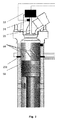
図1〜図3には、本発明によるシステムの同じ実施形態を示す。これらの3つの図には、ピストン61と、シリンダ壁57のリング領域に配置されて(図1のみに示す)潤滑装置252に接続された一連の噴射ユニット251とを有するシリンダの断面図を示している。
1 to 3 show the same embodiment of the system according to the invention. These three figures show a cross-sectional view of a cylinder having a
図1では、ピストン61が低い位置に見られ、その上面がシリンダの掃気ダクト60の下方に存在する。
In FIG. 1, the
図2では、ピストン61が中央位置に見られ、その上面がシリンダの掃気ダクト60の下方に存在する。潤滑油64は、ピストン61が噴射ユニット251を通過する前にピストン61の上方に供給される。潤滑油64の噴射は、シリンダ壁57のリング領域の真上に存在する各噴射ユニット251から行われる。供給は、上方移動中のピストンがリング領域を通過する直前にピストン61の上方位置で行われる。
In FIG. 2, the
図3には、噴射ユニット251がピストン61に対向する位置に存在する状況を示す。
FIG. 3 shows a situation where the
必要に応じて、最上部のピストンリングと最下部のピストンリングとの間における潤滑油の噴射を、ピストンの上方移動中に各噴射ユニットからピストン61上に直接行うこともできる。
If desired, the lubricating oil can be injected between the uppermost piston ring and the lowermost piston ring directly from each injection unit onto the
また、各噴射ユニットからの潤滑油の噴射は、下方移動中のピストンがリング領域を通過する直前に、ピストン61の下方位置においてシリンダ壁のリング領域上に直接行うこともできる。
Further, the injection of the lubricating oil from each injection unit can be performed directly on the ring region of the cylinder wall at a position below the
図4は、実際のエンジン負荷に関する考えられる排気弁閉鎖時間の調整を示す曲線である。閉鎖時間は、排気弁の位置の角度によって表される。 FIG. 4 is a curve showing possible exhaust valve closing time adjustments for actual engine load. The closing time is represented by the angle of the position of the exhaust valve.
X軸は、全エンジン負荷の%で測定したエンジン負荷を示す。 The X axis represents the engine load measured as a percentage of the total engine load.
Y軸は、特定のシリンダの下死点から測定した角度を示す。 The Y axis shows the angle measured from the bottom dead center of a particular cylinder.
実線曲線は、実際のエンジン負荷に応じて閉じられた排気弁の角度を示す。 The solid curve shows the angle of the exhaust valve closed according to the actual engine load.
この実線曲線は、排気弁閉鎖時間の一例を示すものである。本発明者らは、理論的及び実際的な閉鎖時間について述べているので、この角度は絶対的なものではない。例えば、この角度は、排気弁が完全に閉じている時よりも95%閉じている時の方が良好に定めることができる。しかしながら、どのタイプの閉鎖時間であるかが分かった場合、この角度を用いて、潤滑油の注油をいつ行うべきかを定めることができる。 This solid curve shows an example of the exhaust valve closing time. Since we have described theoretical and practical closure times, this angle is not absolute. For example, this angle can be better defined when the exhaust valve is 95% closed than when it is fully closed. However, if the type of closure time is known, this angle can be used to determine when to lubricate.
破線曲線は、完成した潤滑ストローク(潤滑装置のタイミング)の角度を示す。 The dashed curve indicates the angle of the completed lubrication stroke (lubricator timing).
図の下側の曲線は、実際のエンジン負荷に関連して潤滑油の注油をいつ終了すべきであるか(=タイミング点)の一例を示すものである。通常、この角度は、特定のシリンダの下死点から測定される。 The lower curve in the figure shows an example of when lubrication should end (= timing point) in relation to the actual engine load. Usually, this angle is measured from the bottom dead center of a particular cylinder.
図5には、複数のシリンダ及びより多くの潤滑装置を有するエンジン設計及び潤滑システムを示す。本発明によるシステムは、このエンジン設計で使用することができる。このエンジン設計及びこの潤滑システムは、国際公開第2008/009291号にさらに詳細に記載されている。 FIG. 5 shows an engine design and lubrication system having multiple cylinders and more lubrication devices. The system according to the invention can be used in this engine design. This engine design and this lubrication system are described in more detail in WO 2008/009291.
図5には、4つのシリンダ250、及び各シリンダ装置上の8つの噴射ノズル251を概略的に示している。潤滑装置252は、中央コンピュータ253と、通常は各単一の潤滑装置252のためのローカル制御装置254とに接続される。中央コンピュータ253は、中央コンピュータのバックアップを構成するさらなる制御装置255と並列に結合される。また、(油圧ポンプ又は油圧ステーションとすることができる)ポンプをモニタするモニタリングユニット256、負荷をモニタするモニタリングユニット257、及びクランクシャフトの位置をモニタするモニタリングユニット258も設置される。
FIG. 5 schematically shows four
図5の上部には、油圧オイルタンク262内のポンプ261を駆動するモータ260を含む油圧ステーション259を示している。油圧ステーション259は、冷却器263及びフィルタ264をさらに含む。システムオイルは、供給配管265を通じ、弁220を介して潤滑装置に送出される。油圧ステーションは、やはり弁を介して潤滑装置に接続された戻り配管266にさらに接続される。
In the upper part of FIG. 5, a hydraulic station 259 including a motor 260 that drives a
潤滑油は、潤滑油供給タンク(図示せず)から配管267を介して潤滑装置252に送られる。潤滑油は、潤滑装置から配管110を介して噴射ノズル251に送られる。
The lubricating oil is sent from the lubricating oil supply tank (not shown) to the lubricating device 252 via the pipe 267. The lubricating oil is sent from the lubricating device to the
図6に、本発明によるシステムにおいて使用できる潤滑装置の実施形態を示す。この潤滑装置は、国際公開第2008/009291号にさらに詳細に記載されている。 FIG. 6 shows an embodiment of a lubrication device that can be used in the system according to the invention. This lubrication device is described in further detail in WO 2008/009291.
潤滑装置は、装置を作動させるソレノイド弁115及び116が取り付けられた底部110で構成される。底部110の側部には、システム油圧供給部142及びタンクへのシステム油圧復帰部143のためのねじ継手が設けられる。
The lubrication device consists of a bottom 110 to which
駆動油は、2つのソレノイド弁を通じて供給することができ、これらのソレノイド弁のうちの一方が1次ソレノイド弁116であり、他方が2次ソレノイド弁115である。
The drive oil can be supplied through two solenoid valves, one of which is a
初期位置では、1次ソレノイド弁116が作動する。これにより、関連する供給ねじ継手142から1次ソレノイド弁116に駆動油が導かれ、スイッチ弁117を介して装置に入り込み、分配チャネル145を通じて一群の関連する油圧ピストンに導かれる。この状況を図5に示す。
In the initial position, the
1次ソレノイド弁116が故障した場合には、自動的に2次ソレノイド弁115を接続することができる。この弁は、2次ソレノイド弁115を作動させることによって接続される。
If the
これにより、関連する分配流路が加圧される。この圧力によってスイッチ弁117が右側に変位することにより、1次ソレノイド弁116と関連する分配流路との間の接続が遮断される。これにより、このソレノイド弁116に接続された油圧ピストンから圧力が除去される。
This pressurizes the associated distribution channel. Due to this pressure, the
2次ソレノイド弁115を作動させることにより、関連する分配流路及び関連する油圧ピストンが加圧される。この結果、2次ソレノイド弁115を介して装置内に導かれた油によって分配板7が駆動する。
By actuating the
スイッチ弁117は、ばね119を備えることができる。2次ソレノイド弁を通じて圧力が供給されない場合には、このばねが、自動的にスイッチ弁117を上記の初期位置に戻す。
The
スイッチ弁は、このスイッチ弁の戻りを遅らせるようにリストリクタを備えることができる。スイッチ弁は、このスイッチ弁の戻りを遅らせるようにリストリクタを備えることができる。図6では、この制限が、ドレーンピン118とスイッチ弁117との間に形成されたスロットによって決まる。
The switch valve can include a restrictor to delay the return of the switch valve. The switch valve can include a restrictor to delay the return of the switch valve. In FIG. 6, this limitation is determined by the slot formed between the
ソレノイド弁の各々が別個の一群の油圧ピストンに接続されると、ソレノイド弁間の独立性が確実になる。1次ソレノイド弁116と2次ソレノイド弁115との間で切り替えを行うと、スイッチ弁117が一群の1次油圧ピストンから確実に圧力を除去することにより、たとえ1次ソレノイド弁が遮断された場合でも2次ソレノイド弁115の動作が可能になる。
When each of the solenoid valves is connected to a separate group of hydraulic pistons, independence between the solenoid valves is ensured. When switching between the
位置121は、盲ねじを示す。
位置122は、やはり封止機能を有するパッキン(図示せず)を部分的に介してスイッチ弁117の歯止め部120のためのエンドストップ部として部分的に機能する盲ねじ/エンドストップ部の組み合わせを示す。
油圧ピストン6の上方には、分配板7が存在する。ここでは、分配板7を、上側分配板部材125及び下側分配板部材123を有する2分割設計として示している。上側分配板部材125内/上には、注油ピストン21が取り付けられる。駆動及び潤滑に様々な油を使用する装置では、上側分配板部材と下側分配板部材との間にピストンパッキン124が存在する。原理的には、1種類の油を潤滑油と駆動油とに使用すれば十分であると思われる。
A distribution plate 7 exists above the hydraulic piston 6. Here, the distribution plate 7 is shown as a two-part design having an upper
注油ピストン21の周囲には、油圧ピストン6に対する供給圧を遮断した後にピストン21を戻す共通の戻しばね9が存在する。戻しばね9の周囲には、基部ブロック111によって外部的に範囲が定められた小型の潤滑油リザーバ147が存在する。潤滑油は、パッキン138及び139を含む別個のねじ継手を通じて供給される。装置は、パッキン15及び16を含む排出ねじを任意に備えることができる。
Around the
基部ブロック111の上方には、注油ピストン21が往復運動できるように配置されたシリンダブロック112が位置する。注油ピストン21の上方には、ポンプチャンバ148が存在する。このチャンバ内には、ばね14によって付勢された逆止弁球13を有する出口が存在する。さらに、シリンダ壁内の逆止弁/SIP弁に直結されたねじ継手128も設けられる。
Above the
この実施形態には、ストローク調整のために、止めピン/止めねじ66上の位置を変化させることによってウォームホイール130を介してストロークを調整するウォームドライブ131にモータ132が結合された構成を示している。
This embodiment shows a configuration in which a
この実施形態では、ストロークストップの位置を変化させることによってストロークを調整することができる。この実施形態は、固定された原点を用いて後でストロークを調整していた上述の実施形態とは異なる。 In this embodiment, the stroke can be adjusted by changing the position of the stroke stop. This embodiment is different from the above-described embodiment where the stroke is adjusted later using a fixed origin.
実際のストローク長を制御するために、止めピン/止めねじ66に連続して、例えばエンコーダ又は電位差計の形の、ストロークを検出するためのセンサ/ピックアップユニット114が取り付けられる。
In order to control the actual stroke length, a sensor /
位置113は、止めピン/止めねじ構成のハウジングを示す。
位置124は、2つの空間149及び147間のピストンパッキン封止部を示しており、漏れた油は、底部では駆動油側、頂部では潤滑油側においてそれぞれ油圧ピストン6を迂回する。
A
位置127は、基部ブロック111とシリンダブロック112との間のOリング封止部を示す。
位置133は、ウォームホイール130の軸受ケースを締結する締め付けねじを示す。
A
位置134は、底板110と基部ブロック111との間のOリング封止部を示す。
40 1次フライホイールピックアップ部
41 2次フライホイールピックアップ部
42 代替負荷ピックアップ部
43 制御信号線
44 信号
45 信号
46 代替ピックアップ部
47 信号線
48 信号線
49 信号線
50 制御装置
51 信号線
52 信号線
53 アクチュエータ
54 位置ピックアップ部
55 排気弁
56 負荷ピックアップ部
57 壁部
60 掃気ダクト
61 ピストン
62 フライホイール
250 シリンダ
251 噴射ユニット
252 潤滑装置
40 primary flywheel pickup unit 41 secondary flywheel pickup unit 42 alternative load pickup unit 43 control signal line 44 signal 45
Claims (8)
− 各シリンダに対して複数の噴射ユニットを使用する際に、電子制御式の潤滑装置から、前記シリンダの壁部に設けられた噴射ユニットに注油量の潤滑油を圧力下で供給するステップと、
− エンジン負荷を検出するステップと、
− 実際のエンジン負荷に関連して排気弁の閉鎖時間の調整を行う際に、前記エンジン負荷の検出に応じて前記シリンダの排気弁の閉鎖時間を調整するために電子制御を用いるステップと、
− 前記電子制御式の潤滑装置から前記噴射ユニットへの前記潤滑油供給のタイミングを調整するために電子制御を用いるステップと、
を含み、前記方法は、
− 前記エンジン負荷の直接的決定又は間接的決定のためのデータを確立するステップと、
− 前記エンジン負荷のデータを前記潤滑油供給のタイミングの調整に適用することにより、前記潤滑油供給のタイミングが前記エンジン負荷に応じて変化するようにするステップと、
− 前記シリンダの前記排気弁の閉鎖時間を実際のシリンダ負荷について検出するステップと、
− 前記シリンダの前記排気弁の前記閉鎖時間に応じて、前記潤滑油供給のタイミングを電子的に調整する前記電子制御式の潤滑装置により、前記閉鎖時間の前記検出を適用することによって、前記潤滑油供給の前記タイミングが前記エンジン負荷に応じて変化するようにするステップと、
を含む、
ことを特徴とする方法。 A method of lubricating a cylinder with lubricating oil in a two-cycle diesel engine,
Supplying a lubricating amount of lubricating oil under pressure from an electronically controlled lubrication device to an injection unit provided on a wall of the cylinder when using a plurality of injection units for each cylinder;
-Detecting the engine load;
Using electronic control to adjust the exhaust valve closing time of the cylinder in response to detection of the engine load when adjusting the exhaust valve closing time in relation to the actual engine load;
Using electronic control to adjust the timing of the lubricant supply from the electronically controlled lubrication device to the injection unit ;
The method comprises:
-Establishing data for direct or indirect determination of the engine load;
Applying the engine load data to the adjustment of the lubricant supply timing so that the lubricant supply timing changes according to the engine load;
Detecting the closing time of the exhaust valve of the cylinder with respect to the actual cylinder load;
The lubrication by applying the detection of the closure time by means of the electronically controlled lubrication device that electronically adjusts the timing of the lubrication oil supply in response to the closure time of the exhaust valve of the cylinder; Causing the timing of oil supply to change in response to the engine load;
including,
A method characterized by that.
請求項1に記載の方法。 The application of the detection of the closing time of the exhaust valve of the cylinder with respect to the actual cylinder load further comprises the amount of the lubricating oil changing depending on the engine load;
The method of claim 1 .
− 前記位置ピックアップ部の前記検出を用いて、前記潤滑油供給のタイミングを調整するステップと、
をさらに含む請求項1に記載の方法。 -Directly or indirectly determining the position of the exhaust valve using a position pick-up part and detecting the position;
-Adjusting the timing of supply of the lubricating oil using the detection of the position pickup unit;
The method of claim 1 further comprising:
− 前記エンジンの前記フライホイール上の前記ピックアップシステムからのデータを適用して、前記潤滑油供給の前記タイミングのバックアップ及び/又は制御を行うステップと、
をさらに含む請求項2又は3に記載の方法。 Using the load pick-up part for detecting the engine load or the position pick-up part for detecting the position of the exhaust valve to detect the position data, the direction data and the speed data at the same time. Applying a pickup system on the wheel;
Applying data from the pick-up system on the flywheel of the engine to backup and / or control the timing of the lubricant supply;
The method according to claim 2 or 3 , further comprising:
− 選択された動作プロファイルによる負荷に応じて潤滑油供給のタイミングを調整するステップと、
をさらに含む請求項1から4のいずれかに記載の方法。 -Defining various profiles for the operation of the engine;
-Adjusting the timing of lubricating oil supply according to the load according to the selected operating profile;
The method according to any of claims 1 to 4, further comprising a.
− 位置ピックアップ部からのデータを適用して、前記潤滑油供給の前記タイミングのバックアップ及び/又は制御を行うステップと、
をさらに含む請求項1から5のいずれかに記載の方法。 -Determining the position of the exhaust valve directly or indirectly using a position pick-up part and detecting the position;
Applying the data from the position pick-up unit to backup and / or control the timing of the lubricant supply;
The method according to any one of claims 1 to 5 , further comprising:
− 各シリンダに対して複数の噴射ユニットを使用する際に前記シリンダの壁部に設けられる噴射ユニットと、
− 前記噴射ユニットに注油量の潤滑油を圧力下で供給する電子制御式の潤滑装置と、
− エンジン負荷検出手段と、
− アクチュエータに接続されて変位する排気弁と、
− 前記アクチュエータに信号が送信されて、実際のエンジン負荷に関連して前記排気弁の閉鎖時間の調整が行われる際に、前記エンジン負荷の検出に応じて、電子制御して前記シリンダの前記排気弁の前記閉鎖時間のタイミングを調整する制御装置であって、この制御装置は、さらに、電子制御して、前記電子制御式の潤滑装置から前記噴射ユニットへの潤滑油供給のタイミングを調整する前記制御装置と、
を備え、前記システムは、
− 前記エンジン負荷検出手段と、前記エンジン負荷に関する検出データを転送する前記制御装置との間の接続部と、
− 前記エンジン負荷に応じて前記潤滑油供給の前記タイミングを調整するために制御信号を前記潤滑装置に転送する、前記制御装置と前記潤滑装置との間の接続部と、
をさらに備え、
前記エンジン負荷検出手段は、実際のエンジン負荷における前記シリンダの前記排気弁の前記閉鎖時間を検出するピックアップシステムを含み、
前記システムは、前記シリンダの前記排気弁の閉鎖時間を実際のシリンダ負荷について検出し、前記シリンダの前記排気弁の前記閉鎖時間に応じて、前記潤滑油供給のタイミングを電子的に調整する前記潤滑装置により、前記閉鎖時間の前記検出を適用することによって、前記潤滑油供給の前記タイミングが前記エンジン負荷に応じて変化するようにする、
ことを特徴とするシステム。 A system that lubricates cylinders in a two-cycle diesel engine,
An injection unit provided on the wall of the cylinder when using a plurality of injection units for each cylinder;
An electronically controlled lubrication device for supplying an oil amount of lubricating oil to the injection unit under pressure;
-Engine load detection means;
-An exhaust valve connected to the actuator and displaced;
A signal is sent to the actuator to adjust the exhaust valve closing time in relation to the actual engine load and electronically control the exhaust of the cylinder in response to detection of the engine load; A control device for adjusting the timing of the closing time of the valve, wherein the control device further performs electronic control to adjust the timing of supply of lubricating oil from the electronically controlled lubricating device to the injection unit. A control device;
The system comprises:
A connection between the engine load detection means and the control device for transferring detection data relating to the engine load ;
A connection between the control device and the lubrication device for transferring a control signal to the lubrication device to adjust the timing of the lubricant supply according to the engine load;
Further comprising
The engine load detection means includes a pickup system that detects the closing time of the exhaust valve of the cylinder at an actual engine load,
The system detects the closing time of the exhaust valve of the cylinder with respect to an actual cylinder load, and electronically adjusts the timing of supplying the lubricating oil according to the closing time of the exhaust valve of the cylinder. By applying the detection of the closing time by means of a device, the timing of the lubricating oil supply changes according to the engine load.
A system characterized by that.
− 前記排気弁の位置を直接的又は間接的に決定して、該位置を検出する負荷ピックアップ部、及び/又は、
− 前記排気弁の前記位置を直接的又は間接的に決定して、該位置を検出する位置ピックアップ部、
を含み、
前記システムは、
− 前記負荷ピックアップ部又は前記位置ピックアップ部を用いて、位置データ、方向データ及び速度データを同時に検出する、前記エンジンのフライホイール上のピックアップシステムをさらに備える、
請求項7に記載のシステム。 The pickup system is
-A load pickup section for directly or indirectly determining the position of the exhaust valve and detecting the position, and / or
-A position pick-up part for directly or indirectly determining the position of the exhaust valve and detecting the position;
Including
The system
-Further comprising a pickup system on the flywheel of the engine for simultaneously detecting position data, direction data and speed data using the load pickup section or the position pickup section;
The system according to claim 7.
Applications Claiming Priority (3)
| Application Number | Priority Date | Filing Date | Title |
|---|---|---|---|
| DKPA201470144 | 2014-03-25 | ||
| DKPA201470144 | 2014-03-25 | ||
| PCT/DK2015/050067 WO2015144182A1 (en) | 2014-03-25 | 2015-03-25 | Method and system for dosing lubrication oil into cylinders |
Publications (2)
| Publication Number | Publication Date |
|---|---|
| JP2017512937A JP2017512937A (en) | 2017-05-25 |
| JP6574440B2 true JP6574440B2 (en) | 2019-09-11 |
Family
ID=58771145
Family Applications (1)
| Application Number | Title | Priority Date | Filing Date |
|---|---|---|---|
| JP2016558788A Active JP6574440B2 (en) | 2014-03-25 | 2015-03-25 | Method and system for injecting lubricating oil into cylinder |
Country Status (7)
| Country | Link |
|---|---|
| EP (1) | EP2961951B2 (en) |
| JP (1) | JP6574440B2 (en) |
| KR (1) | KR102216353B1 (en) |
| CN (1) | CN106164426B (en) |
| DK (1) | DK2961951T4 (en) |
| HK (1) | HK1219993A1 (en) |
| WO (1) | WO2015144182A1 (en) |
Families Citing this family (8)
| Publication number | Priority date | Publication date | Assignee | Title |
|---|---|---|---|---|
| CN108350772B (en) * | 2015-10-28 | 2020-12-08 | 汉斯延森注油器公司 | Large low speed two-stroke engine with SIP lubricant injector |
| JP7308806B2 (en) | 2015-10-28 | 2023-07-14 | ハンス イェンセン ルブリケイターズ アクティーゼルスカブ | Method and system for lubricating large low-speed two-stroke engines with SIP lube injectors |
| DK179182B1 (en) * | 2016-08-05 | 2018-01-15 | Hans Jensen Lubricators As | Safety system for lubrication of the cylinder of a large slow-running internal combustion engine and a large slow-running two-stroke internal combustion engine |
| DK179482B1 (en) * | 2017-12-13 | 2018-12-14 | Hans Jensen Lubricators A/S | A large slow-running two-stroke engine, a method of lubricating it, and an injector with a hydraulic-driven pumping system for such engine and method |
| US20190211815A1 (en) * | 2018-01-08 | 2019-07-11 | Ge Oil & Gas Compression Systems, Llc | Bypass system for regulating lubrication of reciprocating machines |
| WO2019150172A1 (en) * | 2018-02-05 | 2019-08-08 | Wärtsilä Services Switzerland Ltd | Two-stroke engine and method of operating engine |
| CN109000137B (en) * | 2018-07-20 | 2020-07-31 | 东营市东达机械制造有限责任公司 | Novel motor |
| NO20200639A1 (en) * | 2020-05-29 | 2021-11-30 | Lars Harald Heggen | Gas exchange in internal combustion engines for increased efficiency |
Family Cites Families (14)
| Publication number | Priority date | Publication date | Assignee | Title |
|---|---|---|---|---|
| JPS60169617A (en) * | 1984-02-10 | 1985-09-03 | Mitsubishi Heavy Ind Ltd | Lubricator for diesel engine |
| JPH04318253A (en) * | 1991-04-18 | 1992-11-09 | Mitsubishi Heavy Ind Ltd | Multicylinder engine |
| EP1350929B2 (en) * | 2002-04-04 | 2012-04-11 | Wärtsilä Schweiz AG | Lubrication system for the cylinder of an internal combustion engine and method of lubricating the same |
| DE10311493B4 (en) † | 2003-03-15 | 2005-01-05 | Man B & W Diesel A/S | Two-stroke diesel engine |
| JP4402609B2 (en) * | 2005-02-28 | 2010-01-20 | 三菱重工業株式会社 | Cylinder lubrication device |
| EP1582706B1 (en) * | 2004-03-31 | 2008-07-16 | Mitsubishi Heavy Industries, Ltd. | Internal combustion engine with cylinder lubricating system |
| JP4031772B2 (en) * | 2004-04-16 | 2008-01-09 | 三菱重工業株式会社 | Internal combustion engine with cylinder lubrication device |
| WO2006108438A1 (en) † | 2005-04-14 | 2006-10-19 | Man B & W Diesel A/S | Exhaust valve assembly for a large two-stroke diesel engine |
| JP4575223B2 (en) † | 2005-04-20 | 2010-11-04 | 株式会社マキタ | Rotating tool |
| DK1767751T3 (en) † | 2005-09-23 | 2008-11-17 | Waertsilae Nsd Schweiz Ag | Cylinder lubrication system for a piston combustion engine |
| DK200601005A (en) * | 2006-07-21 | 2008-01-22 | Hans Jensen Lubricators As | Lubricator for a dosing system for cylinder lubricating oil and method for dosing of cylinder lubricating oil |
| JP4657386B2 (en) * | 2008-11-11 | 2011-03-23 | エムエーエヌ・ディーゼル・アンド・ターボ・フィリアル・アフ・エムエーエヌ・ディーゼル・アンド・ターボ・エスイー・ティスクランド | Large two-cycle diesel engine with electronically controlled exhaust valve actuation system |
| EP2395208A1 (en) | 2010-06-11 | 2011-12-14 | Wärtsilä Schweiz AG | Large motor with a cylinder lubrication device and method for lubricating a cylinder of a large motor |
| JP5707274B2 (en) * | 2011-08-12 | 2015-04-22 | 株式会社Ihi | 2-cycle engine |
-
2015
- 2015-03-25 DK DK15738812T patent/DK2961951T4/en active
- 2015-03-25 EP EP15738812.5A patent/EP2961951B2/en active Active
- 2015-03-25 CN CN201580016259.8A patent/CN106164426B/en active Active
- 2015-03-25 WO PCT/DK2015/050067 patent/WO2015144182A1/en active Application Filing
- 2015-03-25 KR KR1020167029582A patent/KR102216353B1/en active IP Right Grant
- 2015-03-25 JP JP2016558788A patent/JP6574440B2/en active Active
-
2016
- 2016-07-06 HK HK16107858.8A patent/HK1219993A1/en unknown
Also Published As
| Publication number | Publication date |
|---|---|
| DK2961951T4 (en) | 2019-12-09 |
| DK2961951T3 (en) | 2017-01-30 |
| KR20160134846A (en) | 2016-11-23 |
| HK1219993A1 (en) | 2017-04-21 |
| EP2961951A1 (en) | 2016-01-06 |
| EP2961951B2 (en) | 2019-10-23 |
| EP2961951A4 (en) | 2016-02-24 |
| KR102216353B1 (en) | 2021-02-17 |
| WO2015144182A1 (en) | 2015-10-01 |
| JP2017512937A (en) | 2017-05-25 |
| CN106164426A (en) | 2016-11-23 |
| CN106164426B (en) | 2018-10-09 |
| EP2961951B1 (en) | 2016-11-30 |
Similar Documents
| Publication | Publication Date | Title |
|---|---|---|
| JP6574440B2 (en) | Method and system for injecting lubricating oil into cylinder | |
| US8813714B2 (en) | Lubrication of cylinders of large diesel engines, such as marine engines | |
| JP5221152B2 (en) | Cylinder surface lubrication method and lubrication apparatus for large diesel engine | |
| KR101365318B1 (en) | Lubricating apparatus and method for dosing cylinder lubricating oil | |
| KR101467429B1 (en) | A cylinder lubrication device for a large slow running two-stroke diesel engine and method of operating the cylinder lubrication system | |
| JP2011256867A (en) | Large engine with cylinder lubrication device and method for lubricating large engine cylinder | |
| EP2097172B1 (en) | Nozzle, lubrication system and internal combustion engine comprising such a nozzle or such a system | |
| DK179118B1 (en) | Cylinder lubrication apparatus for a large two-stroke compression-ignited internal combustion engine | |
| KR20070118127A (en) | A large two-stroke diesel engine with improved fuel efficiency | |
| JP2010534788A (en) | Lubricator and hydraulic piston for engine cylinder lubrication | |
| US7681548B2 (en) | Method and apparatus for lubricating cylinder surface in large diesel engines | |
| KR20130093037A (en) | A large engine including a cylinder lubrication apparatus and method for lubricating a cylinder of a large engine | |
| JP6635461B2 (en) | Lubrication system | |
| WO2007117193A1 (en) | Injection means for a combustion engine | |
| JP4429294B2 (en) | Method for forcibly changing piston ring rotational position and crosshead type 2-stroke internal combustion engine |
Legal Events
| Date | Code | Title | Description |
|---|---|---|---|
| RD04 | Notification of resignation of power of attorney |
Free format text: JAPANESE INTERMEDIATE CODE: A7424 Effective date: 20170425 |
|
| A621 | Written request for application examination |
Free format text: JAPANESE INTERMEDIATE CODE: A621 Effective date: 20180302 |
|
| A131 | Notification of reasons for refusal |
Free format text: JAPANESE INTERMEDIATE CODE: A131 Effective date: 20181129 |
|
| A977 | Report on retrieval |
Free format text: JAPANESE INTERMEDIATE CODE: A971007 Effective date: 20181129 |
|
| A601 | Written request for extension of time |
Free format text: JAPANESE INTERMEDIATE CODE: A601 Effective date: 20190225 |
|
| A521 | Request for written amendment filed |
Free format text: JAPANESE INTERMEDIATE CODE: A523 Effective date: 20190527 |
|
| TRDD | Decision of grant or rejection written | ||
| A01 | Written decision to grant a patent or to grant a registration (utility model) |
Free format text: JAPANESE INTERMEDIATE CODE: A01 Effective date: 20190801 |
|
| A61 | First payment of annual fees (during grant procedure) |
Free format text: JAPANESE INTERMEDIATE CODE: A61 Effective date: 20190816 |
|
| R150 | Certificate of patent or registration of utility model |
Ref document number: 6574440 Country of ref document: JP Free format text: JAPANESE INTERMEDIATE CODE: R150 |
|
| R250 | Receipt of annual fees |
Free format text: JAPANESE INTERMEDIATE CODE: R250 |
|
| R250 | Receipt of annual fees |
Free format text: JAPANESE INTERMEDIATE CODE: R250 |