JP6574170B2 - Cycle aperture flow regulator system - Google Patents

Cycle aperture flow regulator system Download PDF

Info

Publication number
JP6574170B2
JP6574170B2 JP2016517736A JP2016517736A JP6574170B2 JP 6574170 B2 JP6574170 B2 JP 6574170B2 JP 2016517736 A JP2016517736 A JP 2016517736A JP 2016517736 A JP2016517736 A JP 2016517736A JP 6574170 B2 JP6574170 B2 JP 6574170B2
Authority
JP
Japan
Prior art keywords
aperture
fluid
regulator system
flow regulator
cycle
Prior art date
Legal status (The legal status is an assumption and is not a legal conclusion. Google has not performed a legal analysis and makes no representation as to the accuracy of the status listed.)
Active
Application number
JP2016517736A
Other languages
Japanese (ja)
Other versions
JP2016523130A (en
JP2016523130A5 (en
Inventor
サカリアス ハイメ
サカリアス ハイメ
Original Assignee
ノバルティス アーゲー
ノバルティス アーゲー
Priority date (The priority date is an assumption and is not a legal conclusion. Google has not performed a legal analysis and makes no representation as to the accuracy of the date listed.)
Filing date
Publication date
Application filed by ノバルティス アーゲー, ノバルティス アーゲー filed Critical ノバルティス アーゲー
Priority claimed from PCT/IB2014/062252 external-priority patent/WO2014195927A1/en
Publication of JP2016523130A publication Critical patent/JP2016523130A/en
Publication of JP2016523130A5 publication Critical patent/JP2016523130A5/ja
Application granted granted Critical
Publication of JP6574170B2 publication Critical patent/JP6574170B2/en
Active legal-status Critical Current
Anticipated expiration legal-status Critical

Links

Images

Classifications

    • AHUMAN NECESSITIES
    • A61MEDICAL OR VETERINARY SCIENCE; HYGIENE
    • A61FFILTERS IMPLANTABLE INTO BLOOD VESSELS; PROSTHESES; DEVICES PROVIDING PATENCY TO, OR PREVENTING COLLAPSING OF, TUBULAR STRUCTURES OF THE BODY, e.g. STENTS; ORTHOPAEDIC, NURSING OR CONTRACEPTIVE DEVICES; FOMENTATION; TREATMENT OR PROTECTION OF EYES OR EARS; BANDAGES, DRESSINGS OR ABSORBENT PADS; FIRST-AID KITS
    • A61F9/00Methods or devices for treatment of the eyes; Devices for putting-in contact lenses; Devices to correct squinting; Apparatus to guide the blind; Protective devices for the eyes, carried on the body or in the hand
    • A61F9/007Methods or devices for eye surgery
    • A61F9/00736Instruments for removal of intra-ocular material or intra-ocular injection, e.g. cataract instruments
    • AHUMAN NECESSITIES
    • A61MEDICAL OR VETERINARY SCIENCE; HYGIENE
    • A61FFILTERS IMPLANTABLE INTO BLOOD VESSELS; PROSTHESES; DEVICES PROVIDING PATENCY TO, OR PREVENTING COLLAPSING OF, TUBULAR STRUCTURES OF THE BODY, e.g. STENTS; ORTHOPAEDIC, NURSING OR CONTRACEPTIVE DEVICES; FOMENTATION; TREATMENT OR PROTECTION OF EYES OR EARS; BANDAGES, DRESSINGS OR ABSORBENT PADS; FIRST-AID KITS
    • A61F9/00Methods or devices for treatment of the eyes; Devices for putting-in contact lenses; Devices to correct squinting; Apparatus to guide the blind; Protective devices for the eyes, carried on the body or in the hand
    • A61F9/007Methods or devices for eye surgery
    • AHUMAN NECESSITIES
    • A61MEDICAL OR VETERINARY SCIENCE; HYGIENE
    • A61MDEVICES FOR INTRODUCING MEDIA INTO, OR ONTO, THE BODY; DEVICES FOR TRANSDUCING BODY MEDIA OR FOR TAKING MEDIA FROM THE BODY; DEVICES FOR PRODUCING OR ENDING SLEEP OR STUPOR
    • A61M1/00Suction or pumping devices for medical purposes; Devices for carrying-off, for treatment of, or for carrying-over, body-liquids; Drainage systems
    • A61M1/71Suction drainage systems
    • A61M1/74Suction control
    • A61M1/743Suction control by changing the cross-section of the line, e.g. flow regulating valves
    • AHUMAN NECESSITIES
    • A61MEDICAL OR VETERINARY SCIENCE; HYGIENE
    • A61MDEVICES FOR INTRODUCING MEDIA INTO, OR ONTO, THE BODY; DEVICES FOR TRANSDUCING BODY MEDIA OR FOR TAKING MEDIA FROM THE BODY; DEVICES FOR PRODUCING OR ENDING SLEEP OR STUPOR
    • A61M1/00Suction or pumping devices for medical purposes; Devices for carrying-off, for treatment of, or for carrying-over, body-liquids; Drainage systems
    • A61M1/71Suction drainage systems
    • A61M1/74Suction control
    • A61M1/75Intermittent or pulsating suction
    • AHUMAN NECESSITIES
    • A61MEDICAL OR VETERINARY SCIENCE; HYGIENE
    • A61MDEVICES FOR INTRODUCING MEDIA INTO, OR ONTO, THE BODY; DEVICES FOR TRANSDUCING BODY MEDIA OR FOR TAKING MEDIA FROM THE BODY; DEVICES FOR PRODUCING OR ENDING SLEEP OR STUPOR
    • A61M1/00Suction or pumping devices for medical purposes; Devices for carrying-off, for treatment of, or for carrying-over, body-liquids; Drainage systems
    • A61M1/80Suction pumps
    • AHUMAN NECESSITIES
    • A61MEDICAL OR VETERINARY SCIENCE; HYGIENE
    • A61MDEVICES FOR INTRODUCING MEDIA INTO, OR ONTO, THE BODY; DEVICES FOR TRANSDUCING BODY MEDIA OR FOR TAKING MEDIA FROM THE BODY; DEVICES FOR PRODUCING OR ENDING SLEEP OR STUPOR
    • A61M1/00Suction or pumping devices for medical purposes; Devices for carrying-off, for treatment of, or for carrying-over, body-liquids; Drainage systems
    • A61M1/84Drainage tubes; Aspiration tips
    • A61M1/842Drainage tubes; Aspiration tips rotating
    • AHUMAN NECESSITIES
    • A61MEDICAL OR VETERINARY SCIENCE; HYGIENE
    • A61FFILTERS IMPLANTABLE INTO BLOOD VESSELS; PROSTHESES; DEVICES PROVIDING PATENCY TO, OR PREVENTING COLLAPSING OF, TUBULAR STRUCTURES OF THE BODY, e.g. STENTS; ORTHOPAEDIC, NURSING OR CONTRACEPTIVE DEVICES; FOMENTATION; TREATMENT OR PROTECTION OF EYES OR EARS; BANDAGES, DRESSINGS OR ABSORBENT PADS; FIRST-AID KITS
    • A61F9/00Methods or devices for treatment of the eyes; Devices for putting-in contact lenses; Devices to correct squinting; Apparatus to guide the blind; Protective devices for the eyes, carried on the body or in the hand
    • A61F9/007Methods or devices for eye surgery
    • A61F9/00736Instruments for removal of intra-ocular material or intra-ocular injection, e.g. cataract instruments
    • A61F9/00745Instruments for removal of intra-ocular material or intra-ocular injection, e.g. cataract instruments using mechanical vibrations, e.g. ultrasonic
    • AHUMAN NECESSITIES
    • A61MEDICAL OR VETERINARY SCIENCE; HYGIENE
    • A61MDEVICES FOR INTRODUCING MEDIA INTO, OR ONTO, THE BODY; DEVICES FOR TRANSDUCING BODY MEDIA OR FOR TAKING MEDIA FROM THE BODY; DEVICES FOR PRODUCING OR ENDING SLEEP OR STUPOR
    • A61M2210/00Anatomical parts of the body
    • A61M2210/06Head
    • A61M2210/0612Eyes

Description

関連出願の相互参照
本出願は、本発明者により出願された以下の仮特許出願の利益を請求する。
1)2013年6月4日出願のUSPTO仮特許出願第61830792号
2)2013年10月31日出願のUSPTO仮特許出願第61897827号
Cross-reference to related applications This application claims the benefit of the following provisional patent applications filed by the inventor.
1) USPTO provisional patent application No. 61830792 filed on June 4, 2013 2) USPTO provisional patent application No. 61897827 filed on October 31, 2013

発明の分野
本発明は、手術に関し、特に眼科手術において有利に使用され得る改善された流量調整器システムに関する。
FIELD OF THE INVENTION This invention relates to surgery, and more particularly to an improved flow regulator system that can be used advantageously in ophthalmic surgery.

様々な現代の外科的処置では、固体もしくは半固体組織、または他の残屑を含有し得る流体の吸引が必要である。多くの場合において、眼の水晶体嚢内、または肩もしくは膝等の関節内の腔等の体腔から流体を吸引する必要が生じ得る。典型的には、そのような外科的処置の間、体腔内において、周囲圧力または周囲より高い圧力を維持することが望ましい。例えば、人間の眼の水晶体は、患者の視力に影響する白内障の状態を発現する可能性がある。白内障の水晶体は、一般に水晶体乳化と呼ばれる処置において除去および置換されることがある。水晶体乳化処置は、典型的には、眼の水晶体嚢内の水晶体を破壊するために使用される、超音波駆動手術用プローブを用いて行われる。破壊された水晶体は、ハンドピースに結合され水晶体嚢内に突き出る吸引ラインを通して除去される。ハンドピースは、角膜における切開部を通して挿入される先端を有するプローブを有する。ハンドピースは、典型的には、電力を先端の機械的振動運動に変換するいくつかの超音波トランスデューサを含む。先端の遠位端は、吸引ラインと流体連通した開口部を有する。先端の遠位端はまた、かん流ラインと流体連通した開口部を有するスリーブを有してもよい。かん流ラインは、典型的には、かん流流体を手術部位に提供し得る流体の加圧源に接続される。先端の振動運動が、水晶体を小片に破壊する。水晶体断片はまた、かん流/吸引としてより良く知られているかん流ポートを最終的に組み込むことができる従来の超音波ハンドピースまたは専用吸引プローブを使用して、超音波の力を全く使用することなく吸引されてもよく、後述の流量制御および真空サージに関する同じ問題が存在する。水晶体片およびかん流流体は、先端上の吸引開口部を通して吸引ラインに引き込まれる。水晶体乳化は、処置の間に周囲圧力より高い圧力が水晶体嚢および眼の前眼房内に維持され得る場合、成功する可能性がより高い。しかしながら、吸引ラインの遠位端が固体または半固体組織による瞬間的な閉塞から解放された後に、流体サージが生じ得る。閉塞後サージとしても知られるこの流体サージは、かん流ラインを通る流速を一時的に超える、手術用プローブの遠位端の開口部を通る一時的な吸引流速をもたらす可能性があり、それにより眼房の不安定性および最終的な周囲組織の虚脱をもたらし得る。この不安定性および虚脱は、眼の処置の安全性に悪影響をもたらして、潜在的に眼の水晶体嚢の後面に望ましくない損傷を与える可能性があり、かつ/または内皮細胞が角膜から離れて、およびハンドピースの先端の遠位端に向けて不必要に引き込まれる可能性がある。一方、過度に高いかん流流速は、内皮細胞を角膜から離れて不必要に移動させる、または内皮細胞を眼から外に不必要に吸引させる可能性がある。従来の水晶体乳化処置は、典型的には、約350mmHgの真空圧力を使用して行われる。より速い、およびより少ない超音波等の補助エネルギーによる水晶体断片の吸引を支援するために、真空圧力を増加させることが望ましい。超音波は眼を刺激し得るため、超音波作業の低減が望ましい。さらに、最近のフェムト秒レーザ支援白内障手術(FLACS)の導入は、多くの白内障処置において、水晶体材料のレーザにより誘導される著しい軟化を可能とし、超音波エネルギーの使用を不要とし、レーザ軟化水晶体組織材料の吸引のみに依存している。その結果、吸引の有効性を改善し、したがって眼の内側に送達される超音波の量を低減するために、または、超音波乳化され、レーザ軟化された水晶体材料もしくは元来柔らかい水晶体材料を安全および効率的に吸引する能力を改善するために、500mmHgを超える真空を印加することが望ましい。しかしながら、そのようなより高い真空は、手術用プローブへの閉塞後流体サージに関連した外科的リスクを悪化させる。また、例えば、いくつかの整形外科医療処置は、肩または膝内等の関節内の腔から除去されなければならない粒子または他の残屑を生成する。そのような粒子を除去するために、外科医は、吸引チューブを手術部位に結合することができる。体から残屑を引き出す吸引管は、典型的には、壁吸入部に接続された吸入管に接続されるキャニスタに接続される。手術中に手術部位が適切に膨張されることを確実とするために、比較的多量のかん流流体が典型的に体内に導入されて連続的に手術部位をかん流し、病院の真空ラインにより生成された高い流量を相殺するために、典型的に輸液ポンプが必要である。そのような量のかん流流体の体内への導入は、かん流流体の周囲組織への望ましくないまたは過剰の溢出をもたらし得る。また、吸入ラインが固体または半固体組織により閉塞される場合、閉塞後サージが生じ得る。そのような閉塞後サージは、かん流流体の流速を大幅に超える、病院の真空ラインを通る一時的な吸引流速をもたらし、それにより周囲圧力より低い圧力を周囲組織に一時的に印加させる可能性がある。一時的な周囲圧力より低い圧力条件は、体腔の部分的虚脱、吸引管の遠位端近くの組織への損傷、および/または吸引管の遠位端に向けた組織もしくは流体の望ましくない引き込みをもたらし得る。外科的吸引システムは、外科医がシステムに取り付けられた還流スイッチまたはバルブの押下により吸引流の方向を一時反転させることができるように設計され得る。外科医は、例えば、外科医が引き込まれることを望まない吸引管またはハンドピースの遠位先端に向けて組織が引き込まれる場合、これを行うことができる(例えば、外科医が遠位先端により損傷されることを望まない組織)。外科医はまた、吸引管またはハンドピースの遠位先端の閉塞を除去または押し出すために、還流を始めてもよい。現代の閉塞後サージリミッタは、吸引システム内の真空サージを制限し得るが、これは、真空ポンプにより形成された真空が、そのサージリミッタの直径および長さを考慮して安全であるレベルまで制限される場合に限られる。例えば、眼科学において使用される針および管の典型的な直径を考慮して、500mmHgの真空により生成される流量は250cc/分超であり、これは好ましくない眼の虚脱を引き起こし得る。したがって、ベンチュリポンプを使用する先行技術のシステムは、非常に小さい針孔が使用されない限り、穏やかな、例えば300mmHg未満の真空レベルで動作しなければならない。そのような穏やかな真空レベルは、そのようなシステムにおいて利用可能な非閉塞流を大きく制限する。したがって、そのようなサージリミッタは、典型的には、吸引先端の閉塞に応答して圧力差を大きく増加させる蠕動ポンプと共に使用されない。現代の吸引システムにおいて閉塞に応答した圧力上昇がないことは、大きな組織粒子を吸引するその能力を制限する。また、インラインサージリミッタは、外科医が、先端の遠位端に向けてある特定の組織を引き込むために、(先端の遠位端を組織に向けて動かすのではなく)より高い流速を好む場合であっても、閉塞の非存在下で最大流速を低減し得る。また、インラインサージリミッタは、最大還流流速を好ましくない低減したものとし得る。   Various modern surgical procedures require aspiration of fluid that may contain solid or semi-solid tissue, or other debris. In many cases, it may be necessary to draw fluid from a body cavity such as a lens capsule of the eye or a cavity in a joint such as the shoulder or knee. Typically, it is desirable to maintain ambient pressure or higher pressure in the body cavity during such surgical procedures. For example, the crystalline lens of the human eye may develop a cataract state that affects the patient's vision. Cataractous lenses may be removed and replaced in a procedure commonly referred to as lens emulsification. The lens emulsification procedure is typically performed with an ultrasonically driven surgical probe that is used to break the lens in the lens capsule of the eye. The broken lens is removed through a suction line that is bonded to the handpiece and protrudes into the lens capsule. The handpiece has a probe with a tip that is inserted through an incision in the cornea. Handpieces typically include a number of ultrasonic transducers that convert electrical power into tip mechanical vibration motion. The distal end of the tip has an opening in fluid communication with the suction line. The distal end of the tip may also have a sleeve having an opening in fluid communication with the perfusion line. The perfusion line is typically connected to a pressurized source of fluid that can provide perfusion fluid to the surgical site. The oscillating motion of the tip breaks the lens into small pieces. The lens fragment also uses the power of ultrasound entirely, using a conventional ultrasound handpiece or a dedicated suction probe that can eventually incorporate a perfusion port, better known as perfusion / aspiration. The same problems with flow control and vacuum surge described below exist. The lens piece and perfusion fluid are drawn into the suction line through the suction opening on the tip. Lens emulsification is more likely to be successful if pressure higher than ambient pressure can be maintained in the lens capsule and the anterior chamber of the eye during the procedure. However, a fluid surge can occur after the distal end of the suction line is released from momentary occlusion by solid or semi-solid tissue. This fluid surge, also known as post-occlusion surge, can result in a temporary suction flow rate through the opening at the distal end of the surgical probe that temporarily exceeds the flow rate through the perfusion line, thereby It can lead to instability of the chamber and eventual collapse of surrounding tissue. This instability and collapse can adversely affect the safety of the eye treatment, potentially cause unwanted damage to the posterior surface of the lens capsule of the eye, and / or the endothelial cells can leave the cornea, And may be unnecessarily retracted toward the distal end of the handpiece tip. On the other hand, excessively high perfusion flow rates can cause endothelial cells to move unnecessarily away from the cornea, or can cause endothelial cells to be unnecessarily aspirated out of the eye. Conventional lens emulsification procedures are typically performed using a vacuum pressure of about 350 mmHg. It is desirable to increase the vacuum pressure in order to assist the suction of the lens fragment with auxiliary energy such as faster and less ultrasound. Since ultrasound can irritate the eyes, it is desirable to reduce ultrasound work. In addition, the recent introduction of femtosecond laser-assisted cataract surgery (FLACS) allows significant softening of the lens material induced by the laser in many cataract procedures, eliminating the use of ultrasonic energy, and laser softening lens tissue Rely only on material aspiration. As a result, to improve the effectiveness of aspiration and thus reduce the amount of ultrasound delivered to the inside of the eye, or to ultrasonically emulsified and laser softened lens material or naturally soft lens material And in order to improve the ability to suck efficiently, it is desirable to apply a vacuum above 500 mmHg. However, such higher vacuum exacerbates the surgical risk associated with post-occlusion fluid surges on the surgical probe. Also, for example, some orthopedic medical procedures produce particles or other debris that must be removed from intra-articular cavities such as in the shoulder or knee. To remove such particles, the surgeon can couple the suction tube to the surgical site. The suction tube that draws debris from the body is typically connected to a canister that is connected to the suction tube connected to the wall suction part. To ensure that the surgical site is properly inflated during the surgery, a relatively large amount of perfusion fluid is typically introduced into the body to continuously perfuse the surgical site and generated by a hospital vacuum line An infusion pump is typically required to offset the high flow rates made. The introduction of such an amount of perfusion fluid into the body can result in undesirable or excessive overflow of the perfusion fluid into the surrounding tissue. Also, if the inhalation line is occluded by solid or semi-solid tissue, a post-occlusion surge can occur. Such post-occlusion surges can result in a temporary suction flow rate through the hospital vacuum line that greatly exceeds the flow rate of the perfusion fluid, thereby temporarily applying a pressure below ambient pressure to the surrounding tissue. There is. Pressure conditions below the temporary ambient pressure may cause partial collapse of the body cavity, damage to tissue near the distal end of the suction tube, and / or undesired withdrawal of tissue or fluid toward the distal end of the suction tube Can bring. The surgical suction system can be designed to allow the surgeon to temporarily reverse the direction of suction flow by pressing a reflux switch or valve attached to the system. The surgeon can do this if, for example, the tissue is retracted towards the distal tip of a suction tube or handpiece that the surgeon does not want to be retracted (eg, the surgeon is damaged by the distal tip). Organization that does not want). The surgeon may also initiate reflux to remove or push out the obstruction of the distal tip of the suction tube or handpiece. Modern post-occlusion surge limiters can limit vacuum surges in the suction system, which limits the vacuum created by the vacuum pump to a level that is safe considering the diameter and length of the surge limiter Limited to For example, considering the typical diameters of needles and tubes used in ophthalmology, the flow rate generated by a 500 mm Hg vacuum is over 250 cc / min, which can cause undesirable eye collapse. Thus, prior art systems that use a venturi pump must operate at a moderate vacuum level, eg, less than 300 mm Hg, unless a very small needle hole is used. Such gentle vacuum levels greatly limit the non-occlusive flow available in such systems. Thus, such surge limiters are typically not used with peristaltic pumps that greatly increase the pressure differential in response to suction tip blockage. The lack of pressure rise in response to occlusion in modern suction systems limits its ability to aspirate large tissue particles. Inline surge limiters are also used when the surgeon prefers a higher flow rate (rather than moving the distal end of the tip toward the tissue) in order to retract a particular tissue toward the distal end of the tip. Even so, the maximum flow rate can be reduced in the absence of occlusion. Also, the in-line surge limiter may have an undesirably reduced maximum reflux flow rate.

したがって、システム内の真空サージを制限することにより、外科的処置の間体腔内の安定した周囲圧力または周囲より高い圧力を維持する、吸引ライン流量調整器システムを提供することが望ましい。   Accordingly, it is desirable to provide a suction line flow regulator system that maintains a stable or higher ambient pressure in a body cavity during a surgical procedure by limiting vacuum surges in the system.

例えば、吸引ラインを通る体腔外への流速が、体腔内への流速を大きく、または長期間超えることがないように構成される、吸引ライン流量調整器システムを提供することが望ましい。例えば、白内障手術において、吸引流量は、眼から水晶体粒子を迅速に引き込み吸引するのに十分であるべきであるが、閉塞が生じた場合は、吸引ライン内に形成された高真空が、閉塞が解消された後に過度に高い流量を一時生成する可能性があり、これが眼を虚脱させ損傷を生成し得る。   For example, it is desirable to provide a suction line flow regulator system that is configured such that the flow rate out of the body cavity through the suction line does not exceed or exceed the flow rate into the body cavity. For example, in cataract surgery, the suction flow rate should be sufficient to quickly draw and aspirate the lens particles from the eye. It can temporarily generate excessively high flow rates after it is resolved, which can collapse the eye and create damage.

また、利用可能な最も高い真空レベルを使用した場合であっても、かん流ラインを通るかん流流体の制限または低減された流速により安全に機能する吸引ライン流量調整器システムを提供することが望ましい。   It would also be desirable to provide a suction line flow regulator system that functions safely with limited or reduced flow rate of perfusion fluid through the perfusion line, even when using the highest vacuum level available. .

また、閉塞に対する相対的真空応答を大きく増加させ得る吸引ポンプを安全に利用し得る、吸引ライン流量調整器システムを提供することが望ましい。   It would also be desirable to provide a suction line flow regulator system that can safely utilize a suction pump that can greatly increase the relative vacuum response to blockage.

また、閉塞の非存在下の高い吸引流速、および操作者により命令された場合の還流機能を可能とする、吸引ライン流量調整器システムを提供することが望ましい。   It would also be desirable to provide a suction line flow regulator system that allows a high suction flow rate in the absence of a blockage and a reflux function when commanded by the operator.

また、改善された安全性および有効性で、達成可能な最大真空レベルの利点を伴う使用を可能とし得る、吸引ライン流量調整器システムを提供することが望ましい。
また、例えば、ゆっくりでありながらも強力に組織断片を吸引し、超音波乳化等の補足的な組織破砕エネルギーを使用する必要性を低減するために、操作者が高い真空レベルを維持しながら手術部位からの流速を正確に制御することができるようにする、吸引ライン流量調整器システムを提供することが望ましい。
It is also desirable to provide a suction line flow regulator system that can allow use with the benefits of maximum vacuum level achievable with improved safety and effectiveness.
In addition, for example, the operator can perform surgery while maintaining a high vacuum level in order to aspirate tissue fragments slowly but powerfully and reduce the need to use supplemental tissue disruption energy such as ultrasonic emulsification. It would be desirable to provide a suction line flow regulator system that allows the flow rate from the site to be accurately controlled.

手術用プローブの吸引開口部を通した流体および組織断片の外科的吸引の間、体腔の閉塞後の不安定性を防止するためのサイクル式アパーチャ流量調整器システムが開示される。流量調整器システムは、調節可能な断面積を有する流体アパーチャを有する流量調整弁部分を含む。流量調整弁は、弁室および可動部材を有し、双方の部品は共に連動して、可動部材と弁室内に配置された流体通路への入口との間の重複の程度により、流体アパーチャの寸法を画定する。流量調整弁部分は、手術用プローブの吸引開口部を真空源と接続する流体経路内に挿入される。アクチュエータ部分は、流量調整弁部分と接続され、流体アパーチャの断面積を変更するように操作可能である。コントローラが、流体アパーチャの断面積の変化のサイクルをもたらすように、アクチュエータ部分にコマンド信号を提供し、各サイクルは、流体アパーチャの断面積が実質的に低減または最終的に閉鎖される少なくとも1つのセグメントを含む。アパーチャ寸法変動のサイクルは、手術用プローブを通る実質的に一定の流量を生成するのに十分高い周波数で生じるように設定される。手術用プローブにより、手術用プローブ吸引開口部の閉塞の解消により引き起こされる流体サージにより引き起こされる不安定性なしに、流体および組織断片が体腔から吸引され得る。流量は、従来の様式で真空レベルを調節することにより調整され得る。流量はまた、開口部調節サイクルの振幅を変更し、またこのようにして流量調整器システムの弁部分の内側の流体アパーチャの断面積のRMS値を変化させることにより調節され得る。   A cycled aperture flow regulator system is disclosed for preventing instability after occlusion of a body cavity during surgical aspiration of fluid and tissue fragments through the aspiration opening of a surgical probe. The flow regulator system includes a flow regulating valve portion having a fluid aperture having an adjustable cross-sectional area. The flow regulating valve has a valve chamber and a movable member, and both parts work together to determine the size of the fluid aperture depending on the degree of overlap between the movable member and the inlet to the fluid passage located in the valve chamber. Is defined. The flow regulating valve portion is inserted into a fluid path connecting the suction opening of the surgical probe with a vacuum source. The actuator portion is connected to the flow regulating valve portion and is operable to change the cross-sectional area of the fluid aperture. A controller provides a command signal to the actuator portion so as to provide a cycle of change in the fluid aperture cross-sectional area, each cycle having at least one of the fluid aperture cross-sectional areas being substantially reduced or eventually closed. Includes segments. The cycle of aperture dimension variation is set to occur at a frequency high enough to produce a substantially constant flow rate through the surgical probe. With the surgical probe, fluid and tissue fragments can be aspirated from the body cavity without instability caused by a fluid surge caused by the removal of the occlusion of the surgical probe suction opening. The flow rate can be adjusted by adjusting the vacuum level in a conventional manner. The flow rate can also be adjusted by changing the amplitude of the opening adjustment cycle and thus changing the RMS value of the cross section of the fluid aperture inside the valve portion of the flow regulator system.

先行技術の手術用吸引システムの概略図である。1 is a schematic diagram of a prior art surgical suction system. FIG. 本発明のサイクル式アパーチャ流量調整器システムを組み込んだ外科吸引の概略図である。FIG. 6 is a schematic view of surgical suction incorporating the cycle aperture flow regulator system of the present invention. 先行技術の手術用ハンドピースの外観の斜視図である。It is a perspective view of the appearance of a prior art surgical handpiece. 連続吸引経路が露出した図1Cからのハンドピースの側面図である。FIG. 2 is a side view of the handpiece from FIG. 1C with the continuous suction path exposed. 水晶体乳化手術コンソール内に組み込まれた、本発明のサイクル式アパーチャ流量調整器システムの概略図である。1 is a schematic view of a cycle aperture flow regulator system of the present invention incorporated into a phacoemulsification surgical console. FIG. 図1Cからのハンドピース部分の拡大図である。1D is an enlarged view of the handpiece portion from FIG. 1C. FIG. 本発明の流量調整器システムの1つの好ましい回転軸実施形態の概略図である。1 is a schematic view of one preferred rotating shaft embodiment of the flow regulator system of the present invention. FIG. 操作中に生じ得る例示的アパーチャ断面を描写した、図2Aからの流量調整器システムの概略図である。2B is a schematic diagram of the flow regulator system from FIG. 2A depicting an exemplary aperture cross section that may occur during operation. FIG. 操作中に生じ得る例示的アパーチャ断面を描写した、図2Aからの流量調整器システムの概略図である。2B is a schematic diagram of the flow regulator system from FIG. 2A depicting an exemplary aperture cross section that may occur during operation. FIG. 操作中に生じ得る例示的アパーチャ断面を描写した、図2Aからの流量調整器システムの概略図である。2B is a schematic diagram of the flow regulator system from FIG. 2A depicting an exemplary aperture cross section that may occur during operation. FIG. 図2からの流量調整器システムのモデルの断面図である。FIG. 3 is a cross-sectional view of a model of the flow regulator system from FIG. 図2からの流量調整器システムのモデルの断面図である。FIG. 3 is a cross-sectional view of a model of the flow regulator system from FIG. 図2からの流量調整器システムのモデルの断面図である。FIG. 3 is a cross-sectional view of a model of the flow regulator system from FIG. 図2からの流量調整器システムのモデルの断面図である。FIG. 3 is a cross-sectional view of a model of the flow regulator system from FIG. 図2B〜2Dに示される例のそれぞれと一致する、流量調整器システムの1回の回転サイクルに沿った調節可能な流体アパーチャの断面積を示すグラフである。2B is a graph showing the cross-sectional area of the adjustable fluid aperture along one rotation cycle of the flow regulator system, consistent with each of the examples shown in FIGS. サイクル式アパーチャ流量調整器システムの図2に示される回転軸実施形態の手術用ハンドピースにおける1つの実現形態の異なる斜視図、詳細図および断面図である。FIG. 3 is a different perspective, detail and cross-sectional view of one implementation of the surgical handpiece of the rotating shaft embodiment shown in FIG. 2 of the cycle-type aperture flow regulator system. サイクル式アパーチャ流量調整器システムの図2に示される回転軸実施形態の手術用ハンドピースにおける1つの実現形態の異なる斜視図、詳細図および断面図である。FIG. 3 is a different perspective, detail and cross-sectional view of one implementation of the surgical handpiece of the rotating shaft embodiment shown in FIG. 2 of the cycle-type aperture flow regulator system. サイクル式アパーチャ流量調整器システムの図2に示される回転軸実施形態の手術用ハンドピースにおける1つの実現形態の異なる斜視図、詳細図および断面図である。FIG. 3 is a different perspective, detail and cross-sectional view of one implementation of the surgical handpiece of the rotating shaft embodiment shown in FIG. 2 of the cycle-type aperture flow regulator system. サイクル式アパーチャ流量調整器システムの図2に示される回転軸実施形態の手術用ハンドピースにおける1つの実現形態の異なる斜視図、詳細図および断面図である。FIG. 3 is a different perspective, detail and cross-sectional view of one implementation of the surgical handpiece of the rotating shaft embodiment shown in FIG. 2 of the cycle-type aperture flow regulator system. サイクル式アパーチャ流量調整器システムの図2に示される回転軸実施形態の手術用ハンドピースにおける1つの実現形態の異なる斜視図、詳細図および断面図である。FIG. 3 is a different perspective, detail and cross-sectional view of one implementation of the surgical handpiece of the rotating shaft embodiment shown in FIG. 2 of the cycle-type aperture flow regulator system. サイクル式アパーチャ流量調整器システムの図2に示される回転軸実施形態の手術用ハンドピースにおける1つの実現形態の異なる斜視図、詳細図および断面図である。FIG. 3 is a different perspective, detail and cross-sectional view of one implementation of the surgical handpiece of the rotating shaft embodiment shown in FIG. 2 of the cycle-type aperture flow regulator system. サイクル式アパーチャ流量調整器システムの図2に示される回転軸実施形態の手術用ハンドピースにおける1つの実現形態の異なる斜視図、詳細図および断面図である。FIG. 3 is a different perspective, detail and cross-sectional view of one implementation of the surgical handpiece of the rotating shaft embodiment shown in FIG. 2 of the cycle-type aperture flow regulator system. サイクル式アパーチャ流量調整器システムの図2に示される回転軸実施形態の手術用ハンドピースにおける1つの実現形態の異なる斜視図、詳細図および断面図である。FIG. 3 is a different perspective, detail and cross-sectional view of one implementation of the surgical handpiece of the rotating shaft embodiment shown in FIG. 2 of the cycle-type aperture flow regulator system. サイクル式アパーチャ流量調整器システムの図2に示される回転軸実施形態の手術用ハンドピースにおける1つの実現形態の異なる斜視図、詳細図および断面図である。FIG. 3 is a different perspective, detail and cross-sectional view of one implementation of the surgical handpiece of the rotating shaft embodiment shown in FIG. 2 of the cycle-type aperture flow regulator system. サイクル式アパーチャ流量調整器システムの図2に示される回転軸実施形態の手術用ハンドピースにおける1つの実現形態の異なる斜視図、詳細図および断面図である。FIG. 3 is a different perspective, detail and cross-sectional view of one implementation of the surgical handpiece of the rotating shaft embodiment shown in FIG. 2 of the cycle-type aperture flow regulator system. サイクル式アパーチャ流量調整器システムの図2に示される回転軸実施形態の手術用ハンドピースにおける1つの実現形態の異なる斜視図、詳細図および断面図である。FIG. 3 is a different perspective, detail and cross-sectional view of one implementation of the surgical handpiece of the rotating shaft embodiment shown in FIG. 2 of the cycle-type aperture flow regulator system. 弁部分が手術用プローブの内側に配置された流量調整器システムの追加の回転実施形態を組み込んだ手術用ハンドピースにおける、部品の内部構成を示す図である。FIG. 5 shows the internal configuration of the parts in a surgical handpiece incorporating an additional rotating embodiment of the flow regulator system with the valve portion positioned inside the surgical probe. 弁部分が手術用プローブの内側に配置された流量調整器システムの追加の回転実施形態を組み込んだ手術用ハンドピースにおける、部品の内部構成を示す図である。FIG. 5 shows the internal configuration of the parts in a surgical handpiece incorporating an additional rotating embodiment of the flow regulator system with the valve portion positioned inside the surgical probe. 弁部分が手術用プローブの内側に配置された流量調整器システムの追加の回転実施形態を組み込んだ手術用ハンドピースにおける、部品の内部構成を示す図である。FIG. 5 shows the internal configuration of the parts in a surgical handpiece incorporating an additional rotating embodiment of the flow regulator system with the valve portion positioned inside the surgical probe. 図5Aからの弁部分の詳細な断面図である。FIG. 5B is a detailed cross-sectional view of the valve portion from FIG. 5A. 図5Aからの弁部分の詳細な断面図である。FIG. 5B is a detailed cross-sectional view of the valve portion from FIG. 5A. 図5Aからの弁部分の詳細な断面図である。FIG. 5B is a detailed cross-sectional view of the valve portion from FIG. 5A. 図5Aからの弁部分の詳細な断面図である。FIG. 5B is a detailed cross-sectional view of the valve portion from FIG. 5A. 本発明の流量調整器システムの弁部分の構成要素を部分的に提供する、手術用プローブの斜視図および断面図である。FIG. 6 is a perspective view and a cross-sectional view of a surgical probe partially providing the components of the valve portion of the flow regulator system of the present invention. 本発明の流量調整器システムの弁部分の構成要素を部分的に提供する、手術用プローブの斜視図および断面図である。FIG. 6 is a perspective view and a cross-sectional view of a surgical probe partially providing the components of the valve portion of the flow regulator system of the present invention. 本発明の流量調整器システムの弁部分の構成要素を部分的に提供する、手術用プローブの斜視図および断面図である。FIG. 6 is a perspective view and a cross-sectional view of a surgical probe partially providing the components of the valve portion of the flow regulator system of the present invention. 本発明の流量調整器システムの弁部分の構成要素を全て提供する、手術用プローブの斜視図および断面図である。FIG. 2 is a perspective view and cross-sectional view of a surgical probe that provides all of the components of the valve portion of the flow regulator system of the present invention. 本発明の流量調整器システムの弁部分の構成要素を全て提供する、手術用プローブの斜視図および断面図である。FIG. 2 is a perspective view and cross-sectional view of a surgical probe that provides all of the components of the valve portion of the flow regulator system of the present invention. 本発明の流量調整器システムの弁部分の構成要素を全て提供する、手術用プローブの斜視図および断面図である。FIG. 2 is a perspective view and cross-sectional view of a surgical probe that provides all of the components of the valve portion of the flow regulator system of the present invention. 本発明の流量調整器システムの弁部分の構成要素を全て提供する、手術用プローブの斜視図および断面図である。FIG. 2 is a perspective view and cross-sectional view of a surgical probe that provides all of the components of the valve portion of the flow regulator system of the present invention. 本発明の流量調整器システムの弁部分の構成要素を全て提供する、手術用プローブの斜視図および断面図である。FIG. 2 is a perspective view and cross-sectional view of a surgical probe that provides all of the components of the valve portion of the flow regulator system of the present invention. 本発明の流量調整器システムの完全な弁部分を組み込んだ別の手術用プローブの斜視図および断面図である。FIG. 6 is a perspective and cross-sectional view of another surgical probe incorporating the complete valve portion of the flow regulator system of the present invention. 本発明の流量調整器システムの完全な弁部分を組み込んだ別の手術用プローブの斜視図および断面図である。FIG. 6 is a perspective and cross-sectional view of another surgical probe incorporating the complete valve portion of the flow regulator system of the present invention. 本発明の流量調整器システムの完全な弁部分を組み込んだ別の手術用プローブの斜視図および断面図である。FIG. 6 is a perspective and cross-sectional view of another surgical probe incorporating the complete valve portion of the flow regulator system of the present invention. 本発明の流量調整器システムの完全な弁部分を組み込んだ別の手術用プローブの斜視図および断面図である。FIG. 6 is a perspective and cross-sectional view of another surgical probe incorporating the complete valve portion of the flow regulator system of the present invention. 本発明の流量調整器システムの完全な弁部分を組み込んだ別の手術用プローブの斜視図および断面図である。FIG. 6 is a perspective and cross-sectional view of another surgical probe incorporating the complete valve portion of the flow regulator system of the present invention. 本発明の流量調整器システムの完全な弁部分を組み込んだ別の手術用プローブの斜視図および断面図である。FIG. 6 is a perspective and cross-sectional view of another surgical probe incorporating the complete valve portion of the flow regulator system of the present invention. 本発明の流量調整器システムの完全な弁部分を組み込んだ別の手術用プローブの斜視図および断面図である。FIG. 6 is a perspective and cross-sectional view of another surgical probe incorporating the complete valve portion of the flow regulator system of the present invention. 本発明の流量調整器システムの完全な弁部分を組み込んだ別の手術用プローブの斜視図および断面図である。FIG. 6 is a perspective and cross-sectional view of another surgical probe incorporating the complete valve portion of the flow regulator system of the present invention. 本発明の流量調整器システムの完全な弁部分を組み込んだ別の手術用プローブの斜視図および断面図である。FIG. 6 is a perspective and cross-sectional view of another surgical probe incorporating the complete valve portion of the flow regulator system of the present invention. 本発明の流量調整器システムの完全な弁部分を組み込んだ別の手術用プローブの斜視図および断面図である。FIG. 6 is a perspective and cross-sectional view of another surgical probe incorporating the complete valve portion of the flow regulator system of the present invention. 本発明の流量調整器システムの「管内」弁部分を組み込んだ手術用ハンドピースの拡大図である。FIG. 3 is an enlarged view of a surgical handpiece incorporating an “intra-tube” valve portion of the flow regulator system of the present invention. 組織破砕アクチュエータよりも手術用プローブに対しより遠い場所において本発明の弁部分を組み込んだハンドピースの、内部構成要素の側面図である。FIG. 6 is a side view of the internal components of a handpiece incorporating the valve portion of the present invention at a location further from the surgical probe than the tissue disruption actuator. 本発明の流量調整器システムの「プローブ内」弁部分を組み込んだ手術用ハンドピースの拡大図である。FIG. 6 is an enlarged view of a surgical handpiece incorporating an “in-probe” valve portion of the flow regulator system of the present invention. 調節可能な流体経路が断面積の固定RMS値で動作する本発明の実施形態を組み込んだハンドピースの側面図である。FIG. 4 is a side view of a handpiece incorporating an embodiment of the present invention in which an adjustable fluid path operates with a fixed cross-sectional RMS value. 調節可能な流体経路が断面積の固定RMS値で動作する本発明の実施形態を組み込んだハンドピースの側面図である。FIG. 4 is a side view of a handpiece incorporating an embodiment of the present invention in which an adjustable fluid path operates with a fixed cross-sectional RMS value. 操作者が断面積のRMS値を手動で調節することができるようにする機構をさらに組み込んだ、図9Aおよび9Bに示されるものと同様のハンドピースの側面図である。9B is a side view of a handpiece similar to that shown in FIGS. 9A and 9B, further incorporating a mechanism that allows an operator to manually adjust the RMS value of the cross-sectional area. FIG. 本発明のサイクル式アパーチャ流量調整器システムの振動実施形態の概略図である。FIG. 2 is a schematic diagram of a vibrating embodiment of the cycle aperture flow regulator system of the present invention. 本発明のサイクル式アパーチャ流量調整器システムの振動実施形態の概略図である。FIG. 2 is a schematic diagram of a vibrating embodiment of the cycle aperture flow regulator system of the present invention. 本発明のサイクル式アパーチャ流量調整器システムの振動実施形態の概略図である。FIG. 2 is a schematic diagram of a vibrating embodiment of the cycle aperture flow regulator system of the present invention. 本発明のサイクル式アパーチャ流量調整器システムの振動実施形態の概略図である。FIG. 2 is a schematic diagram of a vibrating embodiment of the cycle aperture flow regulator system of the present invention. 本発明のサイクル式アパーチャ流量調整器システムの振動実施形態の概略図である。FIG. 2 is a schematic diagram of a vibrating embodiment of the cycle aperture flow regulator system of the present invention. 各フレーム上の最終的な流体アパーチャの断面積を示す2つの流体通路を有する弁本体に対する、1回の完全振動サイクルに沿った窓を有する可動部材の変位を示す一連の図である。FIG. 6 is a series of illustrations showing the displacement of a movable member with a window along one full vibration cycle for a valve body with two fluid passages showing the cross-sectional area of the final fluid aperture on each frame. 各フレーム上の最終的な流体アパーチャの断面積を示す2つの流体通路を有する弁本体に対する、1回の完全振動サイクルに沿った窓を有する可動部材の変位を示す一連の図である。FIG. 6 is a series of illustrations showing the displacement of a movable member with a window along one full vibration cycle for a valve body with two fluid passages showing the cross-sectional area of the final fluid aperture on each frame. 各フレーム上の最終的な流体アパーチャの断面積を示す2つの流体通路を有する弁本体に対する、1回の完全振動サイクルに沿った窓を有する可動部材の変位を示す一連の図である。FIG. 6 is a series of illustrations showing the displacement of a movable member with a window along one full vibration cycle for a valve body with two fluid passages showing the cross-sectional area of the final fluid aperture on each frame. 各フレーム上の最終的な流体アパーチャの断面積を示す2つの流体通路を有する弁本体に対する、1回の完全振動サイクルに沿った窓を有する可動部材の変位を示す一連の図である。FIG. 6 is a series of illustrations showing the displacement of a movable member with a window along one full vibration cycle for a valve body with two fluid passages showing the cross-sectional area of the final fluid aperture on each frame. 各フレーム上の最終的な流体アパーチャの断面積を示す2つの流体通路を有する弁本体に対する、1回の完全振動サイクルに沿った窓を有する可動部材の変位を示す一連の図である。FIG. 6 is a series of illustrations showing the displacement of a movable member with a window along one full vibration cycle for a valve body with two fluid passages showing the cross-sectional area of the final fluid aperture on each frame. 各フレーム上の最終的な流体アパーチャの断面積を示す2つの流体通路を有する弁本体に対する、1回の完全振動サイクルに沿った窓を有する可動部材の変位を示す一連の図である。FIG. 6 is a series of illustrations showing the displacement of a movable member with a window along one full vibration cycle for a valve body with two fluid passages showing the cross-sectional area of the final fluid aperture on each frame. 各フレーム上の最終的な流体アパーチャの断面積を示す2つの流体通路を有する弁本体に対する、1回の完全振動サイクルに沿った窓を有する可動部材の変位を示す一連の図である。FIG. 6 is a series of illustrations showing the displacement of a movable member with a window along one full vibration cycle for a valve body with two fluid passages showing the cross-sectional area of the final fluid aperture on each frame. 各フレーム上の最終的な流体アパーチャの断面積を示す2つの流体通路を有する弁本体に対する、1回の完全振動サイクルに沿った窓を有する可動部材の変位を示す一連の図である。FIG. 6 is a series of illustrations showing the displacement of a movable member with a window along one full vibration cycle for a valve body with two fluid passages showing the cross-sectional area of the final fluid aperture on each frame. 各フレーム上の最終的な流体アパーチャの断面積を示す2つの流体通路を有する弁本体に対する、1回の完全振動サイクルに沿った窓を有する可動部材の変位を示す一連の図である。FIG. 6 is a series of illustrations showing the displacement of a movable member with a window along one full vibration cycle for a valve body with two fluid passages showing the cross-sectional area of the final fluid aperture on each frame. 各フレーム上の最終的な流体アパーチャの断面積を示す2つの流体通路を有する弁本体に対する、1回の完全振動サイクルに沿った窓を有する可動部材の変位を示す一連の図である。FIG. 6 is a series of illustrations showing the displacement of a movable member with a window along one full vibration cycle for a valve body with two fluid passages showing the cross-sectional area of the final fluid aperture on each frame. 3つの異なる直線振動振幅に対して示された図10Aから10Jからの例からの、1回の完全振動サイクルに沿ったアパーチャ断面積変化を示すグラフである。11 is a graph showing aperture cross-sectional area change along one complete vibration cycle from the examples from FIGS. 10A to 10J shown for three different linear vibration amplitudes. サイクル式アパーチャ流量調整器システムの図10に示される振動実施形態の手術用ハンドピースにおける1つの実現形態の異なる斜視図、詳細図および断面図である。FIG. 11 is a different perspective, detail and cross-sectional view of one implementation of the surgical handpiece of the vibrating embodiment shown in FIG. 10 of the cycle-type aperture flow regulator system. サイクル式アパーチャ流量調整器システムの図10に示される振動実施形態の手術用ハンドピースにおける1つの実現形態の異なる斜視図、詳細図および断面図である。FIG. 11 is a different perspective, detail and cross-sectional view of one implementation of the surgical handpiece of the vibrating embodiment shown in FIG. 10 of the cycle-type aperture flow regulator system. サイクル式アパーチャ流量調整器システムの図10に示される振動実施形態の手術用ハンドピースにおける1つの実現形態の異なる斜視図、詳細図および断面図である。FIG. 11 is a different perspective, detail and cross-sectional view of one implementation of the surgical handpiece of the vibrating embodiment shown in FIG. 10 of the cycle-type aperture flow regulator system. サイクル式アパーチャ流量調整器システムの図10に示される振動実施形態の手術用ハンドピースにおける1つの実現形態の異なる斜視図、詳細図および断面図である。FIG. 11 is a different perspective, detail and cross-sectional view of one implementation of the surgical handpiece of the vibrating embodiment shown in FIG. 10 of the cycle-type aperture flow regulator system. サイクル式アパーチャ流量調整器システムの図10に示される振動実施形態の手術用ハンドピースにおける1つの実現形態の異なる斜視図、詳細図および断面図である。FIG. 11 is a different perspective, detail and cross-sectional view of one implementation of the surgical handpiece of the vibrating embodiment shown in FIG. 10 of the cycle-type aperture flow regulator system. サイクル式アパーチャ流量調整器システムの図10に示される振動実施形態の手術用ハンドピースにおける1つの実現形態の異なる斜視図、詳細図および断面図である。FIG. 11 is a different perspective, detail and cross-sectional view of one implementation of the surgical handpiece of the vibrating embodiment shown in FIG. 10 of the cycle-type aperture flow regulator system. サイクル式アパーチャ流量調整器システムの図10に示される振動実施形態の手術用ハンドピースにおける1つの実現形態の異なる斜視図、詳細図および断面図である。FIG. 11 is a different perspective, detail and cross-sectional view of one implementation of the surgical handpiece of the vibrating embodiment shown in FIG. 10 of the cycle-type aperture flow regulator system. サイクル式アパーチャ流量調整器システムの図10に示される振動実施形態の手術用ハンドピースにおける1つの実現形態の異なる斜視図、詳細図および断面図である。FIG. 11 is a different perspective, detail and cross-sectional view of one implementation of the surgical handpiece of the vibrating embodiment shown in FIG. 10 of the cycle-type aperture flow regulator system. かん流/吸引手術用ハンドピースにおける、本発明の流量調整器システムの1つの実現形態の異なる斜視図、詳細図および断面図である。FIG. 2 is a different perspective, detailed and cross-sectional view of one implementation of the flow regulator system of the present invention in a perfusion / aspiration surgical handpiece. かん流/吸引手術用ハンドピースにおける、本発明の流量調整器システムの1つの実現形態の異なる斜視図、詳細図および断面図である。FIG. 2 is a different perspective, detailed and cross-sectional view of one implementation of the flow regulator system of the present invention in a perfusion / aspiration surgical handpiece. かん流/吸引手術用ハンドピースにおける、本発明の流量調整器システムの1つの実現形態の異なる斜視図、詳細図および断面図である。FIG. 2 is a different perspective, detailed and cross-sectional view of one implementation of the flow regulator system of the present invention in a perfusion / aspiration surgical handpiece. かん流/吸引手術用ハンドピースにおける、本発明の流量調整器システムの1つの実現形態の異なる斜視図、詳細図および断面図である。FIG. 2 is a different perspective, detailed and cross-sectional view of one implementation of the flow regulator system of the present invention in a perfusion / aspiration surgical handpiece. 異なる周波数で動作する本発明のサイクル式アパーチャ流量調整器システムによる、手術用プローブの吸引開口部における流量および圧力測定を示し、流量および圧力リップルが750CPM超で消失し、1500サイクル毎分を超える動作周波数で実質的に一定の流量に変形することを示すグラフである。Shows flow and pressure measurements at the suction opening of a surgical probe with the cycle aperture flow regulator system of the present invention operating at different frequencies, with flow and pressure ripple disappearing above 750 CPM and operating above 1500 cycles per minute It is a graph which shows changing to a substantially constant flow rate with a frequency. アパーチャの開閉の単一サイクル間のスナップショットを描写するシーケンス図である。FIG. 6 is a sequence diagram depicting a snapshot during a single cycle of opening and closing an aperture. 引用により補充された図である。It is the figure supplemented by quotation. 引用により補充された図である。It is the figure supplemented by quotation. 引用により補充された図である。It is the figure supplemented by quotation. 引用により補充された図である。It is the figure supplemented by quotation. 引用により補充された図である。It is the figure supplemented by quotation. 引用により補充された図である。It is the figure supplemented by quotation.

図1Aには、手術用プローブ80の吸引開口部82を調節可能な真空源114と直接接続している流体経路109を示す、先行技術の手術用吸引システムの概略図が示されている。図1Cは、筐体402、かん流管404、かん流スリーブ104、吸引ラインコネクタ406、およびハンドピース400の遠位端に取り付けられた手術用プローブ80を有する、先行技術の手術用ハンドピース400を示す。ハンドピース400の隠れた態様を示す図1Dにおいて、流体経路109が、直接的な管状の様式で手術用プローブ80の吸引開口部から、電気機械的超音波アクチュエータ512および超音波運動シフタ514を横切る吸引ラインコネクタ406まで横切っていることが分かる。先行技術において、吸引ラインコネクタ406を真空源140と接続している流体経路は、単一および直接的吸引配管内に含まれる。   FIG. 1A shows a schematic diagram of a prior art surgical suction system showing a fluid path 109 that directly connects the suction opening 82 of the surgical probe 80 with an adjustable vacuum source 114. FIG. 1C shows a prior art surgical handpiece 400 having a housing 402, a perfusion tube 404, a perfusion sleeve 104, a suction line connector 406, and a surgical probe 80 attached to the distal end of the handpiece 400. Indicates. In FIG. 1D showing the hidden aspect of handpiece 400, fluid path 109 traverses electromechanical ultrasonic actuator 512 and ultrasonic motion shifter 514 from the suction opening of surgical probe 80 in a direct tubular fashion. It can be seen that the suction line connector 406 is crossed. In the prior art, the fluid path connecting the suction line connector 406 to the vacuum source 140 is included in single and direct suction piping.

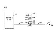
図1Bは、本発明のサイクル式アパーチャ流量調整器システム60を組み込んだ手術用吸引システムの概略図である。システム60の弁部分64は、吸引開口部82と調節可能な真空源114との間の流体経路内に挿入される。流体経路は、第1の(調整器前)流体経路110および第2の(調整器後)流体経路112に分けられ、流体経路は共に、弁64の内側の調節可能な断面積200を有するアパーチャを通して流体的に接続される。システム60のアクチュエータ部分62は、アパーチャ200の断面積を変更するようにシャフト280を動作させる。コントローラ132は、流体アパーチャ200の断面積の変化のサイクルをもたらすように、アクチュエータケーブル142を通してアクチュエータ部分62にサイクルコマンドを提供する。コントローラ132は、各サイクルの少なくとも1つの部分の間、流体アパーチャ200の断面積を大幅に低減するように、アクチュエータ部分62に命令し、断面積の大幅な低減は、アパーチャ200の一時的な完全閉鎖の選択肢を含む。アクチュエータ部分62における運動センサは、運動センサケーブル144を通してコントローラ132に運動フィードバック信号を提供することができる。   FIG. 1B is a schematic illustration of a surgical suction system incorporating the cycle aperture flow regulator system 60 of the present invention. The valve portion 64 of the system 60 is inserted into the fluid path between the suction opening 82 and the adjustable vacuum source 114. The fluid path is divided into a first (pre-regulator) fluid path 110 and a second (post-regulator) fluid path 112, both of which have an adjustable cross-sectional area 200 inside the valve 64. Fluidly connected through. Actuator portion 62 of system 60 operates shaft 280 to change the cross-sectional area of aperture 200. The controller 132 provides a cycle command to the actuator portion 62 through the actuator cable 142 to provide a cycle of change in the cross-sectional area of the fluid aperture 200. The controller 132 commands the actuator portion 62 to significantly reduce the cross-sectional area of the fluid aperture 200 during at least one portion of each cycle, and the significant reduction in cross-sectional area is a temporary completeness of the aperture 200. Includes closure options. The motion sensor in the actuator portion 62 can provide a motion feedback signal to the controller 132 through the motion sensor cable 144.

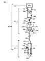
図1Cには、水晶体除去コンソール150の手術用ハンドピース70内に組み込まれた本発明のサイクル式アパーチャ流量調整器システム60の概略図が示されている。図1Dには、図1Cからのハンドピース70領域およびその構成要素の拡大概略図が示されている。かん流ライン102は、かん流プローブ104を通して手術部位に加圧流体100の源を接続する。かん流弁90は、眼の中への流体源100とプローブ104との間の流量を調整することができる。手術用プローブ80は、眼の前眼房等の手術部位内に挿入され得る吸引ポート82を有する。吸引ポート82は、中空のプローブシャフト84およびプローブハブ86を通して、手術用ハンドピース70内に位置するサイクル式アパーチャ流量調整器システム60の弁部分64の入力部170と流体的に接続される。ハブ86はまた、水晶体破砕のために組織破砕エネルギーが組織破砕器アクチュエータ68からプローブ80に効果的に伝達され得るように、プローブ80をハンドピース70の内側の組織破砕アクチュエータ68と結合する。第1の流体経路110は、吸引ポート82と、流量調整器システム60の弁部分64の入力部170を含むアパーチャ200との間に適合する。第1の流体経路110の低減された体積が、高い真空レベルを使用する際の流量調整器システム60の最適性能のための鍵である。この観察を考慮して、流量調整器システムの2つの好ましい実施形態は、第1の流体経路110の体積を最小限に低減するために、現実的に吸引ポート82にできるだけ近くに位置する流量調整器システム60の弁部分64を有する。   FIG. 1C shows a schematic diagram of a cycle aperture flow regulator system 60 of the present invention incorporated into the surgical handpiece 70 of the lens removal console 150. FIG. 1D shows an enlarged schematic view of the handpiece 70 region and its components from FIG. 1C. A perfusion line 102 connects a source of pressurized fluid 100 through the perfusion probe 104 to the surgical site. The perfusion valve 90 can regulate the flow rate between the fluid source 100 and the probe 104 into the eye. The surgical probe 80 has a suction port 82 that can be inserted into a surgical site, such as the anterior chamber of the eye. The suction port 82 is fluidly connected through the hollow probe shaft 84 and probe hub 86 to the input 170 of the valve portion 64 of the cycled aperture flow regulator system 60 located within the surgical handpiece 70. The hub 86 also couples the probe 80 with the tissue disruption actuator 68 inside the handpiece 70 so that tissue disruption energy can be effectively transmitted from the tissue disrupter actuator 68 to the probe 80 for lens disruption. The first fluid path 110 fits between the suction port 82 and the aperture 200 that includes the input 170 of the valve portion 64 of the flow regulator system 60. The reduced volume of the first fluid path 110 is key for optimal performance of the flow regulator system 60 when using high vacuum levels. In view of this observation, the two preferred embodiments of the flow regulator system provide flow regulation that is practically located as close as possible to the suction port 82 to reduce the volume of the first fluid path 110 to a minimum. Having a valve portion 64 of the reservoir system 60.

第1の流体経路110は、好ましくは円形である断面を有するように構築される。直径は、栓塞を防止するためにシャフト84の内側の流体チャネルの直径以上であるべきであり、この直径は、典型的には、水晶体切除プローブの場合0.3mmから1.5mmの間の範囲である。流量調整器システム60の弁部分64の出力180は、手術コンソール150内の真空源114に結合する長さで延在する吸引管111に結合される。第2の流体経路112は、流体アパーチャ200と、出力ポート180および吸引管111を含む真空源114との間に適合する。真空源114には、流体廃棄物貯蔵部116が取り付けられている。   The first fluid path 110 is constructed to have a cross-section that is preferably circular. The diameter should be equal to or greater than the diameter of the fluid channel inside the shaft 84 to prevent plugging, and this diameter typically ranges between 0.3 mm and 1.5 mm for a phacotomy probe. It is. The output 180 of the valve portion 64 of the flow regulator system 60 is coupled to a suction tube 111 that extends a length that couples to the vacuum source 114 in the surgical console 150. The second fluid path 112 fits between the fluid aperture 200 and the vacuum source 114 including the output port 180 and the suction tube 111. A fluid waste storage unit 116 is attached to the vacuum source 114.

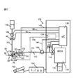
真空制御弁118は、第2の流体経路112内に挿入されて、出力ポート180で利用可能な真空を有効および無効とする。弁118は、プロセッサ130により命令される。逃がし弁120は、第2の流体経路の側枝を、周囲圧力または周囲より高い圧力に接続する。逃がし弁120は、第2の流体経路112の内側の真空を無効化すると共に、操作者により要求された還流操作を可能とするように、プロセッサ130により作動され得る。かん流ライン圧力センサ106は、かん流ライン102内に設置され得る。吸引ライン圧力センサ140は、吸引ライン111内に設置され得る。サイクル式アパーチャ流量調整器システムコントローラ132は、流量調整器制御ケーブル143を通してプロセッサ130からコマンドを受信し得る。かん流ライン圧力センサ信号ケーブル108は、センサ106をコントローラ130と接続する。かん流弁信号ケーブル92は、コントローラ130を弁90と接続する。コントローラ130は、組織破砕器アクチュエータ駆動部134を動作させる。組織破砕器駆動部134は、ケーブル146を通して組織破砕器アクチュエータ68に駆動信号を提供する。吸引ライン圧力センサ140は、ケーブル148を通してコントローラ130に圧力信号を提供する。   A vacuum control valve 118 is inserted into the second fluid path 112 to enable and disable the vacuum available at the output port 180. Valve 118 is commanded by processor 130. A relief valve 120 connects the side branch of the second fluid path to ambient pressure or higher. The relief valve 120 can be actuated by the processor 130 to disable the vacuum inside the second fluid path 112 and to allow the reflux operation requested by the operator. A perfusion line pressure sensor 106 may be installed in the perfusion line 102. The suction line pressure sensor 140 can be installed in the suction line 111. The cycled aperture flow regulator system controller 132 may receive commands from the processor 130 through the flow regulator control cable 143. A perfusion line pressure sensor signal cable 108 connects the sensor 106 to the controller 130. A perfusion valve signal cable 92 connects the controller 130 to the valve 90. The controller 130 operates the tissue crusher actuator driving unit 134. Tissue disruptor drive 134 provides a drive signal to tissue disrupter actuator 68 through cable 146. Suction line pressure sensor 140 provides a pressure signal to controller 130 through cable 148.

好ましい実施形態の記載
軸方向に調節可能なロータおよび「管内」弁部分を有するハンドピース
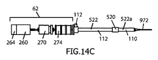
図2から8は、本発明の好ましい実施形態の異なる態様を示す。図2Aにおいて見られるように、本発明のサイクル式アパーチャ流量調整器システム60は、アクチュエータ部分62、および弁部分本体166を有する弁部分64で構成される。流量調整器シャフト280は、アクチュエータ部分62から弁部分64に機械的エネルギーを伝達する。アクチュエータ部分62は、回転シャフト262を有する回転モータ260、および軸方向変位シャフト272を有するボイスコイル直線アクチュエータ270で構成される。回転モータ260の速度は、15RPMから15,000RPMの間で調節可能である。ボイスコイルアクチュエータ270は、適切に調整されたPIDコントローラを使用して駆動される場合、50ミリ秒の負荷応答時間を有する。シャフト280は、同軸回転継手276を介して回転モータシャフト262から回転運動を受ける。シャフト280はまた、アクチュエータシャフト272を介して直線アクチュエータ270から軸方向運動を受ける。軸受282および284により、シャフト280は、シャフト280と272との間のいかなる顕著な軸方向の遊びも制限しながら、直線アクチュエータシャフト272の内側で自由に回転することができる。このようにして、線形アクチュエータ270からシャフト280に正確な軸方向運動が伝達され得る。回転位置センサ264は、モータシャフト262の角度位置を検出し、ケーブル144を通してコントローラ132に角度位置信号を提供することができる。軸方向位置センサ274は、流量調整器シャフト280の軸方向位置を検出し、ケーブル144を通してコントローラ130にシャフト軸方向位置信号を提供することができる。シャフト280は、アクチュエータ部分62を弁部分64と機械的に接続する。弁ロータ290は、弁部分64の弁本体166の内側の弁室292内に収納され、ロータ290およびチャンバ292は共に、顕著な摩擦なしに、および同時に最小限の漏出で弁室292の内側のロータ290の軸方向および回転変位を可能とするように、正確に一致した寸法で構築される。
Description of Preferred Embodiments Handpiece with Axially Adjustable Rotor and “In-Pipe” Valve Portions FIGS. 2-8 illustrate different aspects of preferred embodiments of the present invention. As seen in FIG. 2A, the cycle aperture flow regulator system 60 of the present invention is comprised of an actuator portion 62 and a valve portion 64 having a valve portion body 166. The flow regulator shaft 280 transfers mechanical energy from the actuator portion 62 to the valve portion 64. Actuator portion 62 is comprised of a rotary motor 260 having a rotating shaft 262 and a voice coil linear actuator 270 having an axial displacement shaft 272. The speed of the rotary motor 260 can be adjusted between 15 RPM and 15,000 RPM. Voice coil actuator 270 has a load response time of 50 milliseconds when driven using a properly tuned PID controller. The shaft 280 receives rotational movement from the rotary motor shaft 262 via the coaxial rotary joint 276. Shaft 280 also receives axial motion from linear actuator 270 via actuator shaft 272. Bearings 282 and 284 allow shaft 280 to rotate freely inside linear actuator shaft 272 while limiting any significant axial play between shafts 280 and 272. In this way, accurate axial motion can be transmitted from the linear actuator 270 to the shaft 280. The rotational position sensor 264 can detect the angular position of the motor shaft 262 and provide an angular position signal to the controller 132 through the cable 144. The axial position sensor 274 can detect the axial position of the flow regulator shaft 280 and provide a shaft axial position signal to the controller 130 through the cable 144. Shaft 280 mechanically connects actuator portion 62 with valve portion 64. The valve rotor 290 is housed in a valve chamber 292 inside the valve body 166 of the valve portion 64, and both the rotor 290 and the chamber 292 are inside the valve chamber 292 without significant friction and at the same time with minimal leakage. It is constructed with precisely matched dimensions to allow axial and rotational displacement of the rotor 290.

弁室292は、弁入力ポート170と流体接続されている。弁室292はまた、少なくとも1つの流体通路172を通して、出力ポート180と流体接続されている。弁ロータ290は、通路172への入口が位置する室292の表面と摺動可能に接触する、少なくとも1つの蓋294および少なくとも1つの窓296を有してもよい。アパーチャ200の断面積は、共にロータ290の一体部分である蓋294および窓296と、通路172の入口との間の重なりにより構成される。図2Bから2Dに示されるように、本体166に対するロータ292の相対的な軸方向および回転位置に依存して、蓋294は、部分的または完全に流体通路172を閉塞し得る。環状矢印「a」は、シャフト280およびロータ290の回転運動を示す。直線矢印「b」は、シャフト280およびロータ290の軸方向運動を示す。流体アパーチャ200は、ロータ292の蓋294と流体通路172の入口との間の相対的位置により決定される。流体アパーチャ200の断面積は、蓋294が流体通路172の入口のいかなる部分とも重複しない場合最大である。流体アパーチャ200の断面積は、蓋294および/またはロータ290の一部が流体通路172の入口と完全に重複する場合最少であり、ポート170と180との間の流量の実質的な制限をもたらし、最終的に流量なしの状態を決定付ける。蓋294を有するロータ290の異なる軸方向および回転位置により、通路172の部分的閉塞が生じる際、連続的な範囲の中間的なアパーチャ200の寸法が可能である。図2Bにおいて、弁ロータ290は、別様において任意の回転位置において流体通路172を完全に覆う全長の約3/4だけ本体166内に軸方向に変位される。3つの垂直に配置された円は、ロータ290の3つの異なる回転位置を表し、描写された軸方向位置におけるロータ290の1回転に沿った3つの可能なアパーチャ200の大きさを例示する。   The valve chamber 292 is fluidly connected to the valve input port 170. Valve chamber 292 is also fluidly connected to output port 180 through at least one fluid passage 172. The valve rotor 290 may have at least one lid 294 and at least one window 296 that slidably contact the surface of the chamber 292 where the inlet to the passage 172 is located. The cross-sectional area of the aperture 200 is constituted by the overlap between the lid 294 and the window 296, both of which are an integral part of the rotor 290, and the inlet of the passage 172. As shown in FIGS. 2B to 2D, depending on the relative axial and rotational position of the rotor 292 relative to the body 166, the lid 294 may partially or completely occlude the fluid passage 172. An annular arrow “a” indicates the rotational motion of shaft 280 and rotor 290. The straight arrow “b” indicates the axial movement of the shaft 280 and the rotor 290. The fluid aperture 200 is determined by the relative position between the lid 294 of the rotor 292 and the inlet of the fluid passage 172. The cross-sectional area of the fluid aperture 200 is greatest when the lid 294 does not overlap any part of the inlet of the fluid passage 172. The cross-sectional area of the fluid aperture 200 is minimal when the lid 294 and / or a portion of the rotor 290 completely overlaps the inlet of the fluid passage 172, resulting in a substantial flow restriction between the ports 170 and 180. Finally, determine the state of no flow. Due to the different axial and rotational positions of the rotor 290 with the lid 294, a continuous range of intermediate aperture 200 dimensions is possible when the passage 172 is partially occluded. In FIG. 2B, the valve rotor 290 is otherwise axially displaced into the body 166 by about 3/4 of the total length that completely covers the fluid passage 172 in any rotational position. The three vertically arranged circles represent three different rotational positions of the rotor 290 and illustrate the size of the three possible apertures 200 along one rotation of the rotor 290 in the depicted axial position.

上の円内において、ロータ290および蓋294は、一緒に流体通路172を完全に消失させ、アパーチャ200は、実質的に閉鎖している、または存在しない。図2Bからの中央の円は、ロータ290の別の回転位置を表し、窓296がほとんど通路172と重複してアパーチャ200の中程度の断面積を決定付けるように、蓋294が僅かに存在している。図2Bからの下の円は、非常に小さいアパーチャ200を決定付けるロータ290の別の例示的回転位置を示す。窓296は、通路172への流入を可能とし、アパーチャ200への適合に寄与する蓋294の補足的シリンダ位置である。図2Cからの垂直に配置された円において、図2Bからの対応物と同様のロータ290の回転位置が示されており、この場合、ロータ290の任意の回転位置において通路172の入口の面積の約半分の閉塞を決定付けるロータ290の軸方向位置を有しており、通路172の入口の他の半分は、ロータ290の回転位置に依存して、閉塞が除去されているか、または部分的もしくは完全に蓋294により閉塞されている。ロータ290の1回転の間に達成され得る最大アパーチャ寸法は、図2Cにおいて図2Bよりも大きい。図2Dは、2Bおよび2Cと同様であるが、単に、1回転の間に通路172の入口に重複し得るロータ290の唯一の部分が蓋294であるようにロータ290が軸方向に位置している。この軸方向位置にあるロータ290により、アパーチャ200は、ロータ290の1回転の間、流体通路172の入口の全アパーチャ面積と同等である、可能な最大断面積に到達し得る。   Within the upper circle, the rotor 290 and lid 294 together cause the fluid passage 172 to disappear completely and the aperture 200 is substantially closed or absent. The central circle from FIG. 2B represents another rotational position of the rotor 290 and a slight lid 294 is present so that the window 296 almost overlaps the passage 172 and determines the medium cross-sectional area of the aperture 200. ing. The lower circle from FIG. 2B shows another exemplary rotational position of the rotor 290 that determines a very small aperture 200. Window 296 is a supplemental cylinder position of lid 294 that allows entry into passage 172 and contributes to adaptation to aperture 200. In the vertically arranged circle from FIG. 2C, the rotational position of the rotor 290 is shown similar to the counterpart from FIG. 2B, in this case the area of the inlet of the passage 172 at any rotational position of the rotor 290. Depending on the rotational position of the rotor 290, the other half of the inlet of the passageway 172 has an obstruction removed or partially or It is completely closed by the lid 294. The maximum aperture dimension that can be achieved during one revolution of the rotor 290 is larger in FIG. 2C than in FIG. 2B. FIG. 2D is similar to 2B and 2C, but with the rotor 290 positioned axially so that the only part of the rotor 290 that may overlap the entrance of the passage 172 during one revolution is the lid 294. Yes. With this axial position of the rotor 290, the aperture 200 can reach the maximum possible cross-sectional area that is equivalent to the total aperture area of the inlet of the fluid passage 172 during one revolution of the rotor 290.

図3Aから3Dにおいて、ロータ290の軸方向および回転位置の両方の組み合わせによりどのようにして流体アパーチャ200の大きさが決定されるかを示すために、本体166に対する特定の軸方向回転および軸方向位置にあるロータ290を有する弁部分64の断面図が示されている。平面であるとは限らないが、最も狭いアパーチャ面積は、アパーチャ200の断面積として測定される。図3Eは、ロータ290の回転位置に対するアパーチャ200の寸法を示すグラフであり、少なくとも1回転(角度はX軸に示される)に沿った弁室292の内側の軸方向回転ロータ290は、半径=1mmの円形流体通路172の入口に対して図2B(グラフ上の下のトレース)、図2C(中央のトレース)および図2D(上のトレース)に示される例に近似的に対応する。   3A-3D, to illustrate how the combination of both the axial and rotational position of the rotor 290 determines the size of the fluid aperture 200, a specific axial rotation and axial direction relative to the body 166 is shown. A cross-sectional view of the valve portion 64 with the rotor 290 in position is shown. Although not necessarily a plane, the narrowest aperture area is measured as the cross-sectional area of the aperture 200. FIG. 3E is a graph showing the dimensions of the aperture 200 with respect to the rotational position of the rotor 290, where the axially rotating rotor 290 inside the valve chamber 292 along at least one rotation (the angle is shown in the X axis) is radius = Approximately corresponds to the example shown in FIG. 2B (lower trace on the graph), FIG. 2C (middle trace) and FIG. 2D (upper trace) for the inlet of the 1 mm circular fluid passage 172.

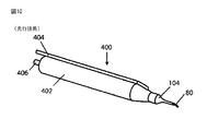
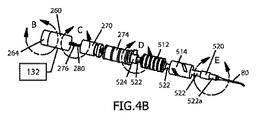
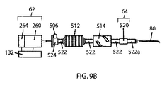
図4Aから4Kは、本発明のサイクル式アパーチャ流量調整器システム60を組み込んだ、眼内からの水晶体の除去のための手術用ハンドピース500の図である。筐体502は、ハンドピース500の内部構成要素を収容し、その支持を提供する。かん流ライン102は、かん流管504と流体連通し、次いでかん流管504は同軸かん流スリーブ508の形態でかん流プローブ104と接続する。吸引管506は、吸引管111と流体連通している。超音波により動作する水晶体切除プローブ510は、図1からのプローブ80と同様に、ハンドピース500に流体的および機械的に取り付けられる。   4A through 4K are views of a surgical handpiece 500 for removal of the lens from the eye, incorporating the cycle aperture flow regulator system 60 of the present invention. The housing 502 houses and provides support for the internal components of the handpiece 500. Perfusion line 102 is in fluid communication with perfusion tube 504, which then connects to perfusion probe 104 in the form of a coaxial perfusion sleeve 508. The suction tube 506 is in fluid communication with the suction tube 111. The lens cutting probe 510 operating with ultrasound is fluidly and mechanically attached to the handpiece 500, similar to the probe 80 from FIG.

図4Bは、筐体502が取り外された状態で見られるようなハンドピース500の内部構成要素を示す。軸管522には、超音波アクチュエータ512および超音波運動変換器514が取り付けられている。管522の内側に適合する図1からの弁部分64(弁64の「管内」構成)に対応する弁部分520が管522内に設置される。水晶体切除プローブ510は、ねじ山88を用いて管522の遠位端と流体的かつ機械的に取り外し可能に接続される。管522の近位端は、シャフトシール524と接続される。管522は、軸方向に配置されたシャフト280を内部に含み、シャフト280の外径と管522の内径との間の循環空間523は、プローブ510を通して吸引される流体および組織断片の循環を促進するのに十分なままである。シャフト280は、水密および気密条件でシャフトシール524に交差し、同軸回転ジョイント276を介して回転アクチュエータ260の回転シャフト262と機械的に相互接続する(図4D)。シャフト262の反対側の端は、回転位置センサ264に取り付けられる。回転位置センサ264は、モータシャフト262の反対側の端に固定された放射状に着磁された円形磁石516、およびホール効果回転位置センサ518(Melexis MLX90316絶対回転位置センサIC)で構成される(図4C)。   FIG. 4B shows the internal components of the handpiece 500 as seen with the housing 502 removed. An ultrasonic actuator 512 and an ultrasonic motion converter 514 are attached to the shaft tube 522. A valve portion 520 corresponding to the valve portion 64 from FIG. 1 that fits inside the tube 522 (the “in-tube” configuration of the valve 64) is installed in the tube 522. The lens cutting probe 510 is fluidly and mechanically removably connected to the distal end of the tube 522 using threads 88. The proximal end of tube 522 is connected with shaft seal 524. Tube 522 includes an axially disposed shaft 280 therein, and a circulation space 523 between the outer diameter of shaft 280 and the inner diameter of tube 522 facilitates circulation of fluid and tissue fragments aspirated through probe 510. It remains enough to do. The shaft 280 intersects the shaft seal 524 under watertight and airtight conditions and mechanically interconnects with the rotating shaft 262 of the rotary actuator 260 via a coaxial rotary joint 276 (FIG. 4D). The opposite end of the shaft 262 is attached to the rotational position sensor 264. The rotational position sensor 264 includes a radially magnetized circular magnet 516 fixed to the opposite end of the motor shaft 262, and a Hall effect rotational position sensor 518 (Melexis MLX90316 absolute rotational position sensor IC). 4C).

線形アクチュエータ270は、シャフト280上に同軸に装着されたシャフト272を有し、シャフト280に、前述のように顕著な軸方向の遊びなしにシャフト272に対して回転する自由度を与える。線形運動センサ274は、線形可変差動変圧器またはLVDT(Measurement Specialties Series MHR+/−0.64mm)内にある。軸方向センサ274は、シャフト280の周りに同軸に装着される中央中空管を有し、シャフト280の軸方向の変位を効果的に測定しながら、センサ274に対してシャフト280の非接触軸方向および回転変位を可能とする。軸方向センサ274を選択するための多くの代替例には、Melexis MLX90292等の直線ホール効果センサおよび直線光直交位相エンコーダがある。アクチュエータ260および270は、センサ264および274と共に、サイクル式アパーチャ流量調整器システム60のアクチュエータ部分62を構成する。   The linear actuator 270 has a shaft 272 that is coaxially mounted on the shaft 280 and provides the shaft 280 with the freedom to rotate relative to the shaft 272 without significant axial play as described above. The linear motion sensor 274 is in a linear variable differential transformer or LVDT (Measurement Specialties Series MHR +/− 0.64 mm). The axial sensor 274 has a central hollow tube that is coaxially mounted about the shaft 280 and effectively measures the axial displacement of the shaft 280 while maintaining a non-contact axis of the shaft 280 relative to the sensor 274. Allows directional and rotational displacement. Many alternatives for selecting the axial sensor 274 include linear Hall effect sensors such as Melexis MLX90292 and linear optical quadrature encoders. Actuators 260 and 270 together with sensors 264 and 274 constitute the actuator portion 62 of the cycled aperture flow regulator system 60.

シャフトシール524の詳細が、シャフトシール本体526、およびシャフト280の周りで調節されたOリング527(図示せず)を含むシャフトシールカバー525を示す図4Eおよび4Hに示される。シャフトシール524は、低い抵抗での水密および気密回転、ならびに管522に対するシャフト280の軸方向の変位を可能にする。シャフトシール524はまた、管522の内部を吸引管506と流体的に接続することに寄与し、弁部分520を真空源114と流体連通させる第2の流体経路112に適合するように寄与する。   Details of the shaft seal 524 are shown in FIGS. 4E and 4H showing a shaft seal cover 525 including a shaft seal body 526 and an O-ring 527 (not shown) adjusted about the shaft 280. The shaft seal 524 allows water and air tight rotation with low resistance and axial displacement of the shaft 280 relative to the tube 522. The shaft seal 524 also contributes to fluidly connecting the interior of the tube 522 with the suction tube 506 and to conform to the second fluid path 112 that allows the valve portion 520 to be in fluid communication with the vacuum source 114.

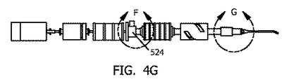
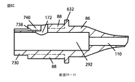
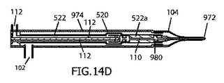
図4Gにおける詳細Gは、管522の内側に実装される「管内」弁部分520を丸で囲んでおり、図4Jおよび4Kにおいてより良く示されている。図4Jは、管522のセグメント内に統合される弁部分520の詳細断面図を描写している。弁520の遠位に残される管522の一部は522aと標示され、第1の流体経路110の構成に寄与する。円筒弁室292は、シャフト280に結合され、アクチュエータ260および270により駆動されるようなシャフト280の回転および軸方向移動に従い、軸方向に回転し軸方向に変位できるようにされた、2自由度(2DOF)を有する一致するロータ290を収容する。   Details G in FIG. 4G circle the “in-tube” valve portion 520 mounted inside the tube 522 and are better shown in FIGS. 4J and 4K. FIG. 4J depicts a detailed cross-sectional view of the valve portion 520 integrated within the segment of the tube 522. The portion of the tube 522 that remains distal to the valve 520 is labeled 522 a and contributes to the configuration of the first fluid path 110. Cylindrical valve chamber 292 is coupled to shaft 280 and is adapted to rotate and displace axially in accordance with the rotation and axial movement of shaft 280 as driven by actuators 260 and 270. Accommodates matching rotor 290 having (2DOF).

プローブ80の吸引ポート82は、プローブシャフト84、プローブハブ86を介して、および第1の流体経路110を構成する管522の遠位部分522aを介して弁室292と直接的に閉塞されずに流体連通している。流体通路172および対称的に配置された第2の流体通路174は、バイパスチャネル528aおよび528bならびに貫通返却ポート530aおよび530bを横切って管522の近位内部と直接的に閉塞されずに流体連通しており、これら全ての流体チャネルは、第2の流体経路112の一体部分である。チャネル528および返却ポート530は、流体構造を完全とするためにロータ290の外側表面を使用して、管522の内壁上にエッチングされた1つ以上のチャネルにより機能的に置換され得る。   The aspiration port 82 of the probe 80 is not directly occluded from the valve chamber 292 via the probe shaft 84, the probe hub 86, and the distal portion 522 a of the tube 522 that constitutes the first fluid path 110. Fluid communication. The fluid passage 172 and the symmetrically disposed second fluid passage 174 are in fluid communication without being directly occluded with the proximal interior of the tube 522 across the bypass channels 528a and 528b and the through return ports 530a and 530b. All these fluid channels are an integral part of the second fluid path 112. Channel 528 and return port 530 may be functionally replaced by one or more channels etched on the inner wall of tube 522 using the outer surface of rotor 290 to complete the fluid structure.

アパーチャ200は、第1の流体経路110と第2の流体経路112との間の接続境界を画定する。弁室292は、ロータ290が、シャフト280により、図2および3に示されるような本発明のアパーチャ200を可能とする軸方向および回転位置に配置される場合にのみ、第2の流体経路112と流体的に接続され得る。様々なサイズの流体アパーチャ200が、流体通路172および174の入口と、ロータ本体および蓋294を含むロータ290の流体通路閉塞部分との間の重なりの程度により決定付けられる。ロータ290の非遮断部分は、窓296として示される。図4Kは、ロータ290と室292との間の回転関係をより良く可視化するために図4Jから抽出された断面図である。ロータ290の1回転の間に、流体アパーチャ200は、最大アパーチャ寸法と最小アパーチャ寸法(断面積)との間で変化し、デバイスにわたるポテンシャル流の実質的な変化をもたらし得ることが理解され得る。アパーチャ200の寸法はまた、ロータ290の軸方向変位に伴って最大アパーチャと最小アパーチャとの間で変化し得る。このようにして、ロータ290の軸方向および回転変位の組み合わせが、最小と最大との間で流体アパーチャ200の断面積を変更し得る。「管内」弁部分520は、これらの図において、より良い理解のために、管522の直径より大きい直径を有するように示される。しかしながら、弁520からの全ての説明された固定流体チャネルは、同様の性能をもって、その外径に影響することなく管522の内側に彫り込まれても、またはエッチングされてもよい。図8Kは、弁部分520の内側の構成要素、主にシャフト280とロータ290との間の関係をより良く示すための、ハンドピース500の拡大図である。   The aperture 200 defines a connection boundary between the first fluid path 110 and the second fluid path 112. The valve chamber 292 is provided in the second fluid path 112 only when the rotor 290 is disposed in an axial and rotational position that allows the aperture 200 of the present invention as shown in FIGS. And can be fluidly connected. Various sizes of the fluid aperture 200 are determined by the degree of overlap between the inlets of the fluid passages 172 and 174 and the fluid passage closure portion of the rotor 290 including the rotor body and lid 294. The non-blocking portion of rotor 290 is shown as window 296. FIG. 4K is a cross-sectional view extracted from FIG. 4J to better visualize the rotational relationship between the rotor 290 and the chamber 292. It can be appreciated that during one revolution of the rotor 290, the fluid aperture 200 can vary between a maximum aperture dimension and a minimum aperture dimension (cross-sectional area), resulting in a substantial change in potential flow across the device. The size of the aperture 200 may also change between the maximum and minimum apertures as the rotor 290 is axially displaced. In this way, the combination of the axial and rotational displacement of the rotor 290 can change the cross-sectional area of the fluid aperture 200 between a minimum and maximum. The “in-tube” valve portion 520 is shown in these figures as having a diameter that is larger than the diameter of the tube 522 for better understanding. However, all the described fixed fluid channels from valve 520 may be engraved or etched inside tube 522 with similar performance without affecting its outer diameter. FIG. 8K is an enlarged view of handpiece 500 to better illustrate the internal components of valve portion 520, primarily the relationship between shaft 280 and rotor 290. FIG.

好ましい実施形態の動作
流体アパーチャ200の断面積のサイクル式の低減は、時計の脱進機構が、ガンギ車が徐々に加速するのを回避するのと同じ様式で、また自動車が制御不能で走行するのを防止し得るエンジンブレーキと同様に、閉塞後サージを防止する。低い周波数で動作する弁64により、流体の個別の「スライス」が、各サイクルの間にアパーチャ200を通過させられる。動作の周波数が増加すると、これらのスライスの体積およびそれらの間の時間間隔が低減される。バルブ64のアパーチャサイクルの動作の周波数が十分に高いと、流体「スライス」は連続流に融合する。高い真空レベルを使用する場合、第1の流体経路110の内側のキャビテーションおよび流体経路抵抗は、アパーチャ低減サイクルの周波数が十分に高い限り、圧力および流量波の積分器として動作して一定レベルを生成する流体RC回路に適合する。これが、サイクルの周波数の増加が圧力および流量波形からのリップルを実質的に排除する1つの理由である。各サイクルの間のアパーチャ寸法の実質的な低減を含む流体アパーチャ断面積サイクルは、最大流量を効果的に制限し、閉塞後サージを防止する。第1の流動経路110の内側の合計キャビテーション気泡の全体積は、閉塞後サージの大きさの決定因子である。第1の流体経路110の体積が小さいほど、最大真空レベルにおけるシステム内の最終的な閉塞後サージの大きさは小さい。
Preferred Embodiment Operation Cyclic reduction in the cross-sectional area of the fluid aperture 200 is the same way that the escapement mechanism of the watch avoids the escape wheel gradually accelerating, and the vehicle runs uncontrollable. As with an engine brake that can prevent the occurrence of a surge, it prevents surges after closing. Valve 64 operating at a low frequency allows individual “slices” of fluid to pass through aperture 200 during each cycle. As the frequency of operation increases, the volume of these slices and the time interval between them is reduced. When the frequency of operation of the aperture cycle of valve 64 is sufficiently high, the fluid “slice” merges into a continuous flow. When using high vacuum levels, the cavitation and fluid path resistance inside the first fluid path 110 acts as an integrator of pressure and flow waves to produce a constant level as long as the frequency of the aperture reduction cycle is sufficiently high. Compatible with fluid RC circuit. This is one reason why increasing the frequency of the cycle substantially eliminates ripple from the pressure and flow waveforms. A fluid aperture cross-sectional cycle that includes a substantial reduction in aperture size during each cycle effectively limits the maximum flow rate and prevents post-occlusion surges. The total volume of total cavitation bubbles inside the first flow path 110 is a determinant of post-occlusion surge magnitude. The smaller the volume of the first fluid path 110, the smaller the magnitude of the final post-occlusion surge in the system at the maximum vacuum level.

流体内に含有される粒子は、図16Aから16Eからのアパーチャ200の開閉の単一サイクルの間のスナップショットを描写するシーケンスにおいて示されるように、動作に影響を与えることなくサイクル機構によりセグメント化され得る。回転リム294は、組織断片化を促進するように鋭くあり得る刃295を有する。アパーチャ200を横切る流れと共に移動する組織断片204は、断片204がセグメント化される様式で刃205により切り込まれ得る。組織断片204の一部208は、室292の内側に保持され得、一方で組織断片204の別の部分206は、アパーチャ200を通過して流体通路172内に流入し得る。速いペースでの弁部分64の内側のアパーチャ200の開閉の繰り返しサイクルにより、本発明のサイクル式アパーチャ流量調整器60の動作に悪影響を及ぼすことなく、流体中に懸濁した全ての組織断片の除去が可能となる。   Particles contained within the fluid are segmented by a cycle mechanism without affecting operation, as shown in the sequence depicting a snapshot during a single cycle of opening and closing aperture 200 from FIGS. 16A to 16E. Can be done. The rotating rim 294 has a blade 295 that can be sharp to promote tissue fragmentation. A tissue fragment 204 that moves with the flow across the aperture 200 may be cut by the blade 205 in a manner that the fragment 204 is segmented. A portion 208 of the tissue fragment 204 may be retained inside the chamber 292, while another portion 206 of the tissue fragment 204 may pass through the aperture 200 and into the fluid passage 172. The repeated cycle of opening and closing the aperture 200 inside the valve portion 64 at a fast pace removes all tissue fragments suspended in the fluid without adversely affecting the operation of the cyclic aperture flow regulator 60 of the present invention. Is possible.

動作中、本発明は、眼の前眼房内からの白内障断片等の体腔からの流体および組織断片を除去するために、有利に使用される。手術用プローブ80は、水晶体が除去される眼の前眼房の内側に挿入される。操作者は、まず、ユーザインターフェース154およびフットペダル152を介してコンソール150からプロセッサ130に命令し、かん流プローブ104を通した眼内への流体のかん流を可能とするためにかん流弁90を開く。かん流が有効とされると、操作者は、手術用プローブ80から遠位開口部82を通して眼の内側から流体および粒子を吸引するように命令することができる。   In operation, the present invention is advantageously used to remove fluid and tissue fragments from body cavities such as cataract fragments from within the anterior chamber of the eye. The surgical probe 80 is inserted inside the anterior chamber of the eye from which the lens is removed. The operator first commands the processor 130 from the console 150 via the user interface 154 and foot pedal 152 to allow perfusion of the fluid into the eye through the perfusion probe 104. open. Once perfusion is enabled, the operator can instruct fluid and particles to be aspirated from the inside of the eye through the distal opening 82 from the surgical probe 80.

本発明の流量調整器システムの操作のために、流量調整器システム60のサイクル式アパーチャ変更機能が、回転アクチュエータ260に電力供給することにより有効とされ、室292の内側のロータ290の軸方向位置により決定付けられるように、ロータ290の回転がロータの回転毎に流体通路200の断面積の少なくとも1つの実質的な低減を生成するように、好ましくは2000RPMを超える速度で弁520の内側のロータ290の連続回転を生成する。弁室292の内側でロータ290が連続的に回転した状態で、流量は、弁室292の内側の回転するロータ290を、較正プロトコルに従う所望の流速を生成する位置に軸方向に変位させるように直線アクチュエータ270に命令することにより調節され得る。室292の内側のロータ290の軸方向位置に関して、アパーチャ200の開放および実質的な閉鎖の両方が、ロータ292の1回転内に存在する操作範囲がある。室292の内側のロータ290の過度の前進は、流体通路172の入口の回転するロータ290の本体との永久的な重なりにより、ロータ290の回転位置に関わらずアパーチャ200の永久的な閉塞を生成し、弁は、永久的に実質的に閉鎖した状態のままとなる。室292の内側のロータ290の過度に少ない変位は、ロータ290の1回転の任意の部分の間、アパーチャ200の寸法を大きく低減することなく、流体通路172の入口上の蓋294の過度に少ない露出を決定付ける。この状態において、ロータ290の回転のそれぞれのサイクルの間、アパーチャ200の一時的な実質的閉塞は生じず、弁は、永久的に開いた位置のままとなり、高い流量調整特性を失う。真空源114の作動により、および逃がし弁120が閉鎖位置にある間に真空制御弁118を開くことにより、大気圧より低い圧力または真空が第2の流体経路112内に提供されなければならない。   For operation of the flow regulator system of the present invention, the cycle aperture change function of the flow regulator system 60 is enabled by powering the rotary actuator 260 and the axial position of the rotor 290 inside the chamber 292. The rotor inside the valve 520, preferably at a speed exceeding 2000 RPM, so that the rotation of the rotor 290 produces at least one substantial reduction in the cross-sectional area of the fluid passage 200 for each rotation of the rotor, as determined by Generate 290 continuous rotations. With the rotor 290 continuously rotating inside the valve chamber 292, the flow rate causes the rotating rotor 290 inside the valve chamber 292 to axially displace to a position that produces the desired flow rate according to the calibration protocol. It can be adjusted by commanding the linear actuator 270. With respect to the axial position of the rotor 290 inside the chamber 292, there is an operating range in which both opening and substantial closing of the aperture 200 exist within one rotation of the rotor 292. Excessive advancement of the rotor 290 inside the chamber 292 creates a permanent blockage of the aperture 200 regardless of the rotational position of the rotor 290 due to permanent overlap with the rotating rotor 290 body at the inlet of the fluid passage 172. The valve then remains permanently substantially closed. Too little displacement of the rotor 290 inside the chamber 292 will cause too little of the lid 294 on the inlet of the fluid passage 172 without significantly reducing the size of the aperture 200 during any part of one revolution of the rotor 290. Determine the exposure. In this state, there is no temporary substantial occlusion of the aperture 200 during each cycle of rotation of the rotor 290, and the valve remains in a permanently open position and loses high flow regulation characteristics. A pressure or vacuum below atmospheric pressure must be provided in the second fluid path 112 by actuation of the vacuum source 114 and by opening the vacuum control valve 118 while the relief valve 120 is in the closed position.

サイクル式アパーチャ流量調整器システムの動作をより良く理解するために、以下の2つの重要な関係を説明することが適切である。   In order to better understand the operation of the cycle aperture flow regulator system, it is appropriate to describe the following two important relationships:

a)所与のロータ290の軸方向位置における、プローブポート82を通して第1の流体経路110内に、および弁520を横切って第2の流体経路112内に循環する非閉塞流量は、第2の流体経路110の内側の真空レベルに依存する。   a) The unoccluded flow rate circulating in the first fluid path 110 through the probe port 82 and across the valve 520 into the second fluid path 112 at a given rotor 290 axial position is a second Depends on the vacuum level inside the fluid path 110.

b)プローブポート82を通して第1の流体経路110内に、および弁520を横切って第2の流体経路112内に循環する非閉塞流量は、室292の内側のロータ290の軸方向位置に依存する。ロータ290および流体通過入口172を含む弁室292の所与の形状因子において、ロータ290の異なる軸方向位置が、ロータ290の各回転に沿ったアパーチャ200の周期的に変化する寸法(断面積)の異なる二乗平均平方根(RMS)演算を決定する。第2の流体経路110での所与の真空レベルにおける弁520を横切る流量は、RMSアパーチャ値に依存する。   b) The unobstructed flow rate circulating in the first fluid path 110 through the probe port 82 and across the valve 520 into the second fluid path 112 depends on the axial position of the rotor 290 inside the chamber 292. . For a given form factor of the valve chamber 292 including the rotor 290 and the fluid passage inlet 172, different axial positions of the rotor 290 may vary periodically (cross-sectional area) of the aperture 200 along each rotation of the rotor 290. Of different root mean square (RMS) operations. The flow rate across the valve 520 at a given vacuum level in the second fluid path 110 depends on the RMS aperture value.

このようにして、本発明のサイクル式アパーチャ流量調整器システムにわたる非閉塞流速は、2つの主要な様式で、すなわち1)第2の流体経路112の内側の真空レベルを決定することにより、および2)ロータ290の軸方向位置を決定することにより調節され得る。第2の流体経路112の内側の真空レベルおよびロータ290の軸方向位置の複数の組み合わせが、非閉塞ポート82内への同様の流速を生成し得る。しかしながら、操作者は、低真空および高真空を使用して同様の吸引流速を得る際に、手術用プローブ510の性能の差に気付くだろう。高真空を使用した場合、組織断片は、低い流速であっても強力に吸引される。   In this way, the unoccluded flow rate across the cycled aperture flow regulator system of the present invention can be achieved in two main ways: 1) by determining the vacuum level inside the second fluid path 112 and 2 ) It can be adjusted by determining the axial position of the rotor 290. Multiple combinations of the vacuum level inside the second fluid path 112 and the axial position of the rotor 290 may produce a similar flow rate into the non-occluded port 82. However, the operator will notice the difference in performance of the surgical probe 510 when using a low vacuum and a high vacuum to obtain a similar suction flow rate. When high vacuum is used, tissue fragments are strongly aspirated even at low flow rates.

低真空を使用した場合、複雑な外科的操作の間、周囲組織を損傷する可能性がより低い。   When low vacuum is used, it is less likely to damage surrounding tissue during complex surgical procedures.

流速は、操作者により、例えばフットペダル152を使用してプロセッサ130に入力信号を提供することによって調節され得る。漸進的なフットペダルの押下は、プロセッサ130に、ロータ290の軸方向位置を変化させて流速を増加または減少させるように直線アクチュエータ270に命令するように指示し得る。また、真空源114により提供される第2の流体経路112内への真空は、プロセッサ130にコマンドを提供することにより変化され得る。ロータ290の軸方向位置および第2の流体経路112の内側の真空レベルの両方のパラメータは、所定の性能プロファイルを得るために同時に調節され得る。本発明のサイクル式流量調整器システムにより有効とされるような異なる真空レベルを使用して所定の流速を選択する可能性は、新規であり有用である。   The flow rate can be adjusted by the operator, for example by providing an input signal to the processor 130 using the foot pedal 152. Gradual foot pedal depression may instruct the processor 130 to change the axial position of the rotor 290 to instruct the linear actuator 270 to increase or decrease the flow rate. Also, the vacuum into the second fluid path 112 provided by the vacuum source 114 can be changed by providing a command to the processor 130. The parameters of both the axial position of the rotor 290 and the vacuum level inside the second fluid path 112 can be adjusted simultaneously to obtain a predetermined performance profile. The possibility of selecting a given flow rate using different vacuum levels as enabled by the cycle flow regulator system of the present invention is new and useful.

かん流が有効とされ、また吸引が有効とされると、操作者は、最終的には唯一の水晶体破砕エネルギーとして真空の力のみを使用して、吸引により組織断片を把持し、眼からそれらを除去することができる。代替として、白内障断片が単純な吸引には硬過ぎる場合、超音波等の補足的な水晶体破砕エネルギーの源が適用され得る。ハブ86は、手術用プローブ80を、軸方向超音波アクチュエータ512および超音波運動変換器514で構成される組織破砕アクチュエータ68と結合する。アクチュエータ512および変換器514は、一緒に超音波運動を手術用プローブ80に伝達し、水晶体材料を乳化するための効果的方法を提供し得る。組織破砕駆動部134によりアクチュエータ68に提供される駆動周波数に依存して、プローブ80の機械的振動のパターンは、シャフト軸に平行(長手方向)となるように、または代替としてシャフト軸に沿って回転するように(ねじ山方向)プログラムされ得る。本発明のサイクル式アパーチャ流量調整器システムの注目すべき特徴は、室292の内側のロータ290の運動が、組織破砕アクチュエータ68により手術用プローブ80に伝達され得る最終的な変位の軸に一致する回転および軸方向成分を有することである。この特徴は、サイクル式流量調整器システム60および組織破砕アクチュエータ68の同時操作を可能とするため、根本的に重要である。   When perfusion is enabled and suction is enabled, the operator eventually uses only the force of the vacuum as the only lens fragmentation energy to grasp the tissue fragments by suction and remove them from the eye. Can be removed. Alternatively, if the cataract fragment is too hard for simple aspiration, a supplemental source of lens crushing energy such as ultrasound can be applied. The hub 86 couples the surgical probe 80 with a tissue disruption actuator 68 comprised of an axial ultrasonic actuator 512 and an ultrasonic motion transducer 514. Together, the actuator 512 and the transducer 514 can transmit an ultrasonic motion to the surgical probe 80 and provide an effective method for emulsifying the lens material. Depending on the drive frequency provided to the actuator 68 by the tissue disruption drive 134, the pattern of mechanical vibration of the probe 80 may be parallel (longitudinal) to the shaft axis, or alternatively along the shaft axis. Can be programmed to rotate (thread direction). A notable feature of the cycle aperture flow regulator system of the present invention is that the movement of the rotor 290 inside the chamber 292 coincides with the final axis of displacement that can be transmitted to the surgical probe 80 by the tissue disruption actuator 68. Having rotational and axial components. This feature is fundamentally important because it allows simultaneous operation of the cycle flow regulator system 60 and the tissue disruption actuator 68.

直線変位センサ274から位置フィードバック信号を使用して直線アクチュエータ270を操作することが望ましい。この構成において、アクチュエータコントローラ132は、シャフト280の軸方向位置情報を受信し、ロータ290を所望の軸方向設定点に位置付けるように直線アクチュエータの動作を命令して、メモリ内に保存された較正手順からのデータに従う所望の非閉塞流速を生成する。センサ274により提供される位置フィードバック信号によって、操作者により命令された所望の非閉塞流速設定点に従い、弁室292に対するロータ290の軸方向位置を正確および迅速に調節するために、例えば比例・積分・微分フィルタ(PID)を使用して、制御ループをアクチュエータコントローラ132に組み込むことができる。   It is desirable to operate the linear actuator 270 using the position feedback signal from the linear displacement sensor 274. In this configuration, the actuator controller 132 receives the axial position information of the shaft 280, commands the operation of the linear actuator to position the rotor 290 at the desired axial set point, and stores the calibration procedure stored in memory. To produce the desired non-occlusive flow rate according to the data from The position feedback signal provided by sensor 274 provides, for example, proportional and integral to accurately and quickly adjust the axial position of rotor 290 relative to valve chamber 292 according to the desired non-occluding flow rate set point commanded by the operator. A control loop can be incorporated into the actuator controller 132 using a differential filter (PID).

本発明のサイクル式流量調整器の基本操作モードにおいて、所与の真空レベルに対する流速は、ロータ290に一定の回転を提供して、各サイクルの間のアパーチャ200の断面積の実質的な低減の少なくとも一部を含むアパーチャ200の断面積のサイクル変動を生成しながら、ロータ290の軸方向位置を決定することにより設定される。   In the basic mode of operation of the cycle flow regulator of the present invention, the flow rate for a given vacuum level provides a constant rotation to the rotor 290 to substantially reduce the cross-sectional area of the aperture 200 during each cycle. It is set by determining the axial position of the rotor 290 while generating a cycle variation of the cross-sectional area of the aperture 200 including at least a part thereof.

いくつかの状況において、例えば、回転蓋294と流体通路チャネル172および174との間に所定の軸方向配列が望まれる場合、ロータ290の回転位置の制御を有することが有利となり得る。この動作は、例えば、還流操作中に、または、コントローラ132もしくはプロセッサ130によりいくつかの不具合が検出された場合に永久的に開いたアパーチャ200を確実とするために、興味深いものとなり得る。回転センサ264は、コントローラ132に正確な角度位置信号を提供し得る。コントローラ132は、回転アクチュエータ260に、選択された角度位置において回転シャフト262を能動的に停止するように命令し得る(例えば、この操作を可能とするブラシレスDCモータを使用する場合)。   In some situations, it may be advantageous to have control of the rotational position of the rotor 290, for example, if a predetermined axial alignment is desired between the rotating lid 294 and the fluid passage channels 172 and 174. This operation can be interesting, for example, to ensure that the aperture 200 is permanently open during the reflux operation or if some malfunction is detected by the controller 132 or the processor 130. The rotation sensor 264 can provide an accurate angular position signal to the controller 132. The controller 132 may instruct the rotary actuator 260 to actively stop the rotary shaft 262 at a selected angular position (eg, when using a brushless DC motor that allows this operation).

システムプライミングの間、各手順の開始時に較正ルーチンを行うことができる。較正ルーチンの例は、以下に存在し得る:a)かん流プローブ104を吸引ポート82と流体的に接続するための、先行技術の試験チャンバの設置、b)弁90が閉鎖された状態で圧力センサ106を使用した加圧流体源100における静的かん流圧力の検出、c)加圧流体源100から流体経路110および112内への流動を可能とするための、弁90の開放。d)真空源114の作動による所定の真空レベルの提供、e)所望のRPMでロータ290を一定に回転させるための回転アクチュエータ260の作動、f)ロータ290の軸方向位置の一連の段階的調節に沿ったデータ取得シーケンスの実行に続く、各ステップにおけるロータ290の軸方向位置、センサ106からのかん流圧力読み取り値、およびセンサ140からの真空読み取り値のメモリへの保存、g)その目的のためにかん流ライン102抵抗および静的圧力と定常状態圧力との間で測定された圧力降下を組み込んだ、ロータ290の軸方向位置の測定ステップにおける非閉塞流速の計算、h)回転するロータ290の軸方向位置および真空源114からの真空レベルを調節することによって、操作者により命令される設定点に流速を調節するために、コントローラ132により使用される伝達関数の構築。較正ルーチンはまた、異なる回転モータ速度での段階的測定を組み込んでもよい。ロータ290の回転速度の変更は、例えば、ポート82内の真空/流量波におけるより多くのリップルが、水晶体断片の引き込みまたは破砕を補助し得るいくつかの状況において、利点をもたらし得る。流量調整器システム60の較正ルーチンはまた、両方のシステムが手術中に同時に操作される場合に生じ得る流量ドリフトに対して調節するための、組織破砕アクチュエータ68が異なる出力設定で作動している状態での流速の決定を含んでもよい。   During system priming, a calibration routine can be performed at the beginning of each procedure. Examples of calibration routines may exist: a) installation of a prior art test chamber for fluidly connecting the perfusion probe 104 with the suction port 82, b) pressure with the valve 90 closed. Detection of static perfusion pressure in pressurized fluid source 100 using sensor 106, c) Opening of valve 90 to allow flow from pressurized fluid source 100 into fluid paths 110 and 112. d) providing a predetermined vacuum level by actuating the vacuum source 114, e) actuating the rotary actuator 260 to constantly rotate the rotor 290 at the desired RPM, f) a series of stepwise adjustments of the axial position of the rotor 290. Storage of the axial position of the rotor 290 at each step, the perfusion pressure reading from the sensor 106, and the vacuum reading from the sensor 140 in memory following execution of the data acquisition sequence along The calculation of the unoccluded flow rate in the measuring step of the axial position of the rotor 290, incorporating the perfusion line 102 resistance and the pressure drop measured between the static and steady state pressures, h) the rotating rotor 290 By adjusting the axial position of and the vacuum level from the vacuum source 114, the set point commanded by the operator is flowed. In order to adjust the build of the transfer function used by the controller 132. The calibration routine may also incorporate stepped measurements at different rotary motor speeds. Changing the rotational speed of the rotor 290 can provide advantages in some situations, for example, where more ripple in the vacuum / flow wave in the port 82 can assist in the pulling or breaking of the lens fragments. The calibration routine of the flow regulator system 60 also has the tissue disruption actuator 68 operating at different power settings to adjust for flow drift that can occur when both systems are operated simultaneously during surgery. Determination of the flow rate at.

還流操作:操作者は、例えば、組織の望ましくない部分がプローブ80から遠位開口部82により捕捉された場合に、フットペダルスイッチを押下することにより、還流操作を要求することができる。還流は、弁64の回転アクチュエータ260の動作を維持しながら、弁118を短時間閉鎖し弁120を開放することによって、第2の流体経路112の内側の圧力の一時的増加を提供することにより提供され得る。還流操作の流速(還流速度)は、還流中にロータ290を所望の軸方向位置に同時に位置付けることにより調節され得る。還流操作の代替の方法は、還流期間の間アパーチャ200が連続的に開いたままとなるように、ロータ290を停止させることを考慮し得る。   Refluxing operation: An operator can request a refluxing operation, for example, by depressing a foot pedal switch when an undesired portion of tissue is captured by the distal opening 82 from the probe 80. Reflux provides a temporary increase in pressure inside the second fluid path 112 by closing valve 118 briefly and opening valve 120 while maintaining operation of rotary actuator 260 of valve 64. Can be provided. The flow rate of the reflux operation (reflux rate) can be adjusted by simultaneously positioning the rotor 290 at the desired axial position during reflux. An alternative method of reflux operation may consider stopping the rotor 290 such that the aperture 200 remains continuously open during the reflux period.

本発明のサイクル式アパーチャ流量調整器システムの動作は、先行技術のシステムに勝るいくつかの利点を提供する。最も妥当なものには、閉塞後サージが事実上排除され、合併症のリスクが低減されることが含まれる。閉塞後サージなしに最大限に高い真空レベルを使用して、水晶体組織断片を吸引する効率を増加させ、超音波乳化等の補足的な水晶体破砕エネルギーの必要性を低減することができる。   The operation of the cycled aperture flow regulator system of the present invention provides several advantages over prior art systems. The most reasonable includes the fact that post-occlusion surges are virtually eliminated and the risk of complications is reduced. A maximally high vacuum level without surge after occlusion can be used to increase the efficiency of sucking lens tissue fragments and reduce the need for supplemental lens crushing energy such as ultrasonic emulsification.

別の妥当な利点は、本システムが、非閉塞流速が吸引ライン真空レベルから独立して調整され得るように動作するという点である。これにより、水晶体材料のゆっくりでありながら効率的な除去のために、高真空と共に低い流速を設定することができ、患者の回復時間および手術室の患者の回転率を改善することができる。   Another reasonable advantage is that the system operates such that the non-occluding flow rate can be adjusted independently of the suction line vacuum level. This allows a low flow rate to be set with a high vacuum for slow but efficient removal of the lens material, improving patient recovery time and patient turnover in the operating room.

吸引ライン真空設定および非閉塞流速設定の異なる組み合わせを、ユーザインターフェース154のパネルまたはフットペダル152を使用してプログラムおよび調節することができる。これらの調節は、ユーザインターフェースで一定に設定されてもよく、または、例えばフットペダルの押下のレベルに応答して連続的に変化してもよい。図15中のグラフにおいて見られるように、本発明のサイクル式アパーチャ流量調整器システムにより生成される吸引ポート82で検出される圧力および流量リップル効果は、アパーチャ断面積変動のサイクルの周波数を、変動が僅かとなる程度(この例では毎分2000サイクル超)まで増加させることにより、徐々に低減される。   Different combinations of suction line vacuum settings and non-occlusive flow rate settings can be programmed and adjusted using the panel or foot pedal 152 of the user interface 154. These adjustments may be set constant at the user interface or may change continuously in response to, for example, the level of foot pedal depression. As seen in the graph in FIG. 15, the pressure and flow ripple effects detected at the suction port 82 generated by the cycle aperture flow regulator system of the present invention vary the frequency of the aperture cross-sectional area variation cycle. Is gradually reduced by increasing it to a small extent (in this example, more than 2000 cycles per minute).

弁520は、第1の流体経路110の体積が設計により低く維持される限り、管522のより近位の位置に位置してもよい。また、より厳しくない仕様の用途において、または比較的低い真空レベルを使用する予定である場合には、弁のより近位の場所を考慮することができる。弁520のより近位の場所の図が、図8Lに示されている。   The valve 520 may be located in a more proximal position of the tube 522 as long as the volume of the first fluid path 110 is kept low by design. Also, in less severe specification applications, or if a relatively low vacuum level is to be used, a more proximal location of the valve can be considered. A view of a more proximal location of valve 520 is shown in FIG. 8L.

安全性に関する考慮点:動作中、本発明のサイクル式アパーチャ流量調整器システム60は、流体アパーチャ200の断続的な大幅低減を高い周波数で生成する。この動作モードは、ほぼ流量ゼロから最大流量の間で調節可能な、手術用プローブ80を通る吸引ラインへの実質的に一定の流量を生成する。例えば超音波水晶体乳化により熱を発生し得る組織破砕器アクチュエータと組み合わせて流量調整器システム60を操作する場合、安全対策が実施されなければならない。低い流量は、超音波水晶体乳化中に手術用プローブにより生成される角膜熱傷(切開熱損傷としても知られる)の既知のリスク因子である。調整器60からのコントローラ132が、コンソール150からのプロセッサ130と通信して、角膜熱傷等の外科合併症を促進するリスクとみなされ得る操作条件を回避することが望ましい。例えば、その操作が潜在的に有害な発熱を含む場合、組織破砕器アクチュエータ68の作動の前に、調整器60のアパーチャ設定により、および真空源114設定により、最低一定流速が決定され得る。また、弁64の内側の流量対する予想外の連続的な著しい制約を生成する不具合が生じ得る。この状態は、例えば、1つのアクチュエータが動作を停止し、ロータ290が流体通路遮断位置に永久的に残された場合に生じ得る。コントローラ132は、センサ264および274からの信号からそのような状態を検出し、超音波エネルギーをオフにする等の、合併症を回避するための予防策をとるための対策をとるために、プロセッサ130または操作者に故障アラーム信号を伝達することができる。フェイルセーフアクチュエータもまた、永久的な流体通路遮断のリスクの低減に寄与し得る。例えば、モータ260は、モータの回転速度が安全性限界を下回る場合にシャフト262の軸方向の引き込みをもたらす遠心機構を組み込んでもよい。この状態において、シャフト262の引き込みは、シャフト280を介してロータ290をチャンバ292の内側の「安全モード」位置に変位させ、流体通路174または174の入口を遮断し得るロータ290の部分はなく、流量調整弁は、開いた状態に維持される。   Safety considerations: In operation, the cycle aperture flow regulator system 60 of the present invention produces intermittent significant reductions in the fluid aperture 200 at high frequencies. This mode of operation produces a substantially constant flow rate to the suction line through the surgical probe 80 that can be adjusted between approximately zero flow rate and maximum flow rate. For example, when operating the flow regulator system 60 in combination with a tissue disrupter actuator that can generate heat by ultrasonic lens emulsification, safety measures must be implemented. Low flow is a known risk factor for corneal burns (also known as incisional heat damage) generated by a surgical probe during ultrasonic lens emulsification. It is desirable for the controller 132 from the regulator 60 to communicate with the processor 130 from the console 150 to avoid operating conditions that may be considered a risk of promoting surgical complications such as corneal burns. For example, if the operation involves a potentially harmful fever, the lowest constant flow rate may be determined by the aperture setting of the regulator 60 and by the vacuum source 114 setting prior to actuation of the tissue disrupter actuator 68. There can also be inconveniences that create unexpected continuous significant constraints on the flow rate inside the valve 64. This condition can occur, for example, when one actuator stops operating and the rotor 290 is permanently left in the fluid path blocking position. The controller 132 detects such conditions from the signals from the sensors 264 and 274 and takes a processor to take precautions to avoid complications such as turning off ultrasonic energy. A failure alarm signal can be communicated to 130 or the operator. Fail-safe actuators can also contribute to reducing the risk of permanent fluid path blockage. For example, the motor 260 may incorporate a centrifugal mechanism that provides axial retraction of the shaft 262 when the rotational speed of the motor is below a safety limit. In this state, retraction of the shaft 262 displaces the rotor 290 via the shaft 280 to a “safe mode” position inside the chamber 292 and there is no portion of the rotor 290 that can block the fluid passage 174 or 174 inlet, The flow regulating valve is maintained in an open state.

追加の実施形態(1)
軸方向に調節可能なロータおよび「プローブ内」弁部分を有するハンドピース:手術用プローブは、弁部分64の一部を含む。
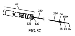
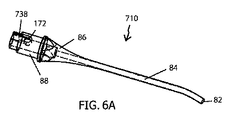
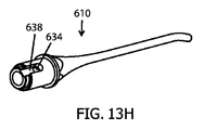
図5Aから5Gは、最大真空レベルでの使用のために第1の流体経路110の体積を最小まで低減しながら、依然として高い流量安定性を提供するための代替のアプローチとして、本発明のサイクル式アパーチャ流量調整器システム60の弁部分64が手術用プローブ610内に組み込まれた、追加の実施形態の態様を示す。手術用プローブ610が取り付けられたハンドピース600が、図5Aに示されている。筐体502が取り外されたハンドピース600が、図5Bに示されており、流量調整器システム60のアクチュエータ部分62が、以前に図4において詳細に示されたのと同様に配置されているのが示されている。図5Cにおいて、組織破砕アクチュエータ部分68および管522が共に取り外され、その下のシャフト280および手術用プローブ610が露出したハンドピース600が示されている。この実施形態において、シャフト280は、シャフト280の遠位端が、弁部分64を含む手術用プローブ610のハブ領域86と作用可能に接触するように延在している。図5Dは、管522と操作上結合された手術用プローブ610を示す。図5Eから5Gは、図5Dからの詳細領域Gの断面図を示す。ロータ290は、シャフト280の遠位端で組み込まれ、管522へのプローブ610の取り付けにより、室壁630により囲まれた弁室292内に機能的に配置され、完全な弁部分64に適合する。この実施形態において、ロータ290は、2つの窓296aおよび296b(図8Fにおいても見られる)に適合する2つの円形開口部を有する管形状の蓋294を有する。プローブ610は、流体通路172および174に組み込まれる。通路172および174の入口と、蓋294における窓296aおよび296bとの間の重なりの拡張は、アパーチャ200の断面積を決定付ける。図5Eにおいて、ロータ290は、窓296aおよび296bが流体通路チャネル172および174の入口に実質的に一致し、ほぼ最大寸法のアパーチャ200を決定付けるような軸方向および回転位置に位置しているように示されている。図5Fにおいて、ロータ290は、窓296aおよび296bが流体通路チャネル172および174の入口に部分的に一致し、中間的な寸法のアパーチャ200を決定付けるような軸方向および回転位置に位置しているように示されている。図5Fにおいて、ロータ290は、窓296aおよび296bが流体通路チャネル172および174の入口に一致せず、アパーチャ200の大幅な低減を決定付けるような軸方向および回転位置に位置しているように示されている。図6Aから6Cは、さらに詳細に、単一の流体通路172を有するチャンバ292を含む弁部分64を組み込んだ手術用プローブ710の、斜視図、正面図および断面図を示す。手術用プローブ710は、ハブ領域86内に弁部分64の固定された構成部品を提供する。これらの部品は、本質的に、1つの流体通路172を有する室壁730により限られた弁室292である。図6Cにおいて見られるように、弁排出チャネル738は、管522の内部壁と組み合わせて(図5E)、ハブ86からの切り出し体積740により通常適合される。弁排出チャネル738は、流体通路172を管522の内側の循環空間523と流体的に接続するが、これらは全て、第2の流体チャネル112への寄与部分である。ハブのリム632は、動作中に管522の遠位端とハブ86との間の密閉を提供するように配置され、両方ともねじ山88の締まりばめにより圧縮される。ロータ290は、ハンドピース600の一体部分であり、プローブ710が操作上ハンドピース600に取り付けられる場合、室292の内側に機能的に配置される。この実施形態は、弁部分64の弁室292の磨耗によりシステム60の性能が低下する前に、手術用プローブ710を交換することにより弁64の固定部分を頻繁に交換することを可能にする。ロータ290は、より拡張された用途にわたり磨耗に耐えることができるように、セラミック、ステンレススチールまたはチタン等の耐摩耗性の材料で製造され得る。図8Mは、部品の相補的動作をより良く例示するための、1)アクチュエータ部分62、シャフト280およびロータ290を少なくとも提供するハンドピース600、ならびに2)弁部分64の弁室292を提供する手術用プローブ610(全ての部品は、本発明のサイクル式アパーチャ流量調整器システム60に適合するように連動する)からの、ハンドピース600および手術用プローブ610の拡大図である。
Additional embodiment (1)
Handpiece with axially adjustable rotor and “in-probe” valve portion: The surgical probe includes a portion of the valve portion 64.
FIGS. 5A through 5G show the cycle of the present invention as an alternative approach to still provide high flow stability while reducing the volume of the first fluid path 110 to a minimum for use at the maximum vacuum level. FIG. 6 illustrates aspects of an additional embodiment in which the valve portion 64 of the aperture flow regulator system 60 is incorporated into the surgical probe 610. A handpiece 600 with attached surgical probe 610 is shown in FIG. 5A. The handpiece 600 with the housing 502 removed is shown in FIG. 5B, and the actuator portion 62 of the flow regulator system 60 is positioned as previously shown in detail in FIG. It is shown. In FIG. 5C, the handpiece 600 is shown with the tissue disruption actuator portion 68 and the tube 522 both removed and the underlying shaft 280 and surgical probe 610 exposed. In this embodiment, the shaft 280 extends such that the distal end of the shaft 280 is in operative contact with the hub region 86 of the surgical probe 610 that includes the valve portion 64. FIG. 5D shows surgical probe 610 operably coupled with tube 522. 5E to 5G show cross-sectional views of the detailed region G from FIG. 5D. The rotor 290 is incorporated at the distal end of the shaft 280 and is functionally disposed within the valve chamber 292 surrounded by the chamber wall 630 by fitting the probe 610 to the tube 522 to fit the complete valve portion 64. . In this embodiment, the rotor 290 has a tube-shaped lid 294 with two circular openings that fit into the two windows 296a and 296b (also seen in FIG. 8F). Probe 610 is incorporated into fluid passages 172 and 174. The expansion of the overlap between the entrances of the passages 172 and 174 and the windows 296a and 296b in the lid 294 determines the cross-sectional area of the aperture 200. In FIG. 5E, the rotor 290 is located in an axial and rotational position such that the windows 296a and 296b substantially coincide with the inlets of the fluid passage channels 172 and 174 and determine the aperture 200 of approximately maximum size. Is shown in In FIG. 5F, the rotor 290 is positioned in an axial and rotational position such that the windows 296a and 296b partially coincide with the inlets of the fluid passage channels 172 and 174 and determine the intermediate size aperture 200. As shown. In FIG. 5F, the rotor 290 is shown as being positioned in an axial and rotational position such that the windows 296a and 296b do not coincide with the inlets of the fluid passage channels 172 and 174 and determine the significant reduction of the aperture 200. Has been. FIGS. 6A through 6C show perspective, front, and cross-sectional views of a surgical probe 710 that incorporates a valve portion 64 that includes a chamber 292 having a single fluid passage 172 in more detail. Surgical probe 710 provides a fixed component of valve portion 64 within hub region 86. These parts are essentially a valve chamber 292 limited by a chamber wall 730 having a single fluid passage 172. As seen in FIG. 6C, the valve discharge channel 738 is typically fitted with a cut volume 740 from the hub 86 in combination with the inner wall of the tube 522 (FIG. 5E). The valve discharge channel 738 fluidly connects the fluid passage 172 with the circulation space 523 inside the tube 522, all of which are contributions to the second fluid channel 112. Hub rim 632 is positioned to provide a seal between the distal end of tube 522 and hub 86 during operation, and both are compressed by an interference fit of threads 88. Rotor 290 is an integral part of handpiece 600 and is functionally disposed inside chamber 292 when probe 710 is operationally attached to handpiece 600. This embodiment allows frequent replacement of the fixed portion of the valve 64 by replacing the surgical probe 710 before the performance of the system 60 is degraded due to wear of the valve chamber 292 of the valve portion 64. The rotor 290 can be made of a wear resistant material such as ceramic, stainless steel or titanium so that it can withstand wear over more extended applications. FIG. 8M provides a better illustration of the complementary motion of the components: 1) a handpiece 600 that provides at least an actuator portion 62, a shaft 280 and a rotor 290, and 2) a surgery that provides a valve chamber 292 of the valve portion 64. FIG. 6 is an enlarged view of the handpiece 600 and surgical probe 610 from the probe 610 (all components interlocked to fit the cycle aperture flow regulator system 60 of the present invention).

追加の実施形態(2)
軸方向に調節可能なロータおよび「プローブ内」弁部分を有するハンドピース:手術用プローブは、完全な弁部分64を含む。
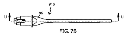
別の追加の実施形態を、図7Aから7Eに示すが、流量調整水晶体切除プローブ910が提供され、ロータ窓928を有する一致するロータ924を含む完全弁部分64を備える。室292の内側にすでに挿入されたロータ924が供給されている。ロータ924は、ロータを適所に維持するためにプローブ910により提供される蓋と組み合わせて、ロータ保持具として動作する円形狭窄932を有する。弁室292の内側で部分的に圧縮され、使用可能な軸方向変位範囲の外側端に向けてロータ924を押すばね930が、軸方向に配置されている。ばね930は、回転および圧縮の間、室292内で、およびロータ290と共に摩擦なしで摺動し得る。ハンドピース600内に組み込まれたシャフト280は、ロータ924の相補的機能926に一致するように設計される遠位端機能922を有し、弁動作のために回転運動をロータ924に同軸で伝達するのに効果的な回転インターロックをもたらす。シャフト280は、ばね930に対してロータ924にわたり制御された押出し動作を負荷し得る。このようにして、ロータ924は、コントローラ132により命令されるように回転および軸方向の力を伝達するシャフト280の動作により、正確に回転され、軸方向に位置付けられ得る。流量調整動作は、前に説明した実施形態と同様である。流量調整器システム60の完全弁部分64が各プローブ910の交換により改修され、反復的使用によりもたらされる劣化が回避される本実施形態を有する本発明のサイクル式流量調整器システムを提供することが有利となり得る。
Additional embodiment (2)
Handpiece with axially adjustable rotor and “in-probe” valve portion: The surgical probe includes a complete valve portion 64.
Another additional embodiment is shown in FIGS. 7A through 7E, wherein a flow regulating phacosectomy probe 910 is provided and includes a full valve portion 64 that includes a matching rotor 924 having a rotor window 928. A rotor 924 already inserted inside the chamber 292 is supplied. The rotor 924 has a circular constriction 932 that acts as a rotor holder in combination with a lid provided by the probe 910 to keep the rotor in place. A spring 930 that is partially compressed inside the valve chamber 292 and pushes the rotor 924 toward the outer end of the usable axial displacement range is disposed axially. Spring 930 may slide without friction during rotation and compression, within chamber 292 and with rotor 290. A shaft 280 incorporated within the handpiece 600 has a distal end feature 922 designed to match the complementary feature 926 of the rotor 924 and coaxially transmits rotational motion to the rotor 924 for valve operation. Provides an effective rotating interlock. The shaft 280 may load a controlled extrusion action across the rotor 924 relative to the spring 930. In this way, the rotor 924 can be accurately rotated and axially positioned by the operation of the shaft 280 transmitting rotational and axial forces as commanded by the controller 132. The flow rate adjustment operation is the same as that of the previously described embodiment. To provide a cycled flow regulator system of the present invention having the present embodiment in which the full valve portion 64 of the flow regulator system 60 is modified by replacing each probe 910 to avoid degradation caused by repeated use. Can be advantageous.

追加の実施形態(3)
向上した組織断片化機能を有する「プローブ内」弁部分
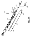
図7からの実施形態の変形例を図8Aから8Jに示すが、手術用プローブ950は、弁室292の底部と一体化した内部拍車状構造952をさらに含む完全弁部分64を有する。保持された弁ロータ954は、遠心力により周縁部に引き寄せられる室292の内側のロータ954の回転中に組織を圧縮および断片化するために、プローブ950からの拍車状構造952と組み合わせて動作する鋭いリブ等の組織断片化機能をさらに組み込んでもよい。鋭いリブ956をさらに組み込んだ従来のロータを、図8Fに示す。弁室292の内側の拍車状構造の組み込みは、ばね930のためにほとんど空間を残さない。したがって、シャフト280とロータ954との間のより精巧な回転−軸方向インターロックが、この実施形態により提供される。この代替のインターロックは、シャフト280によるロータ954の回転および軸方向駆動を可能とし、ばねを必要とせずに、回転と共に軸方向の引き込みおよび押し出し動作を可能とする。向上した組織断片化能力を有するこの実施形態の使用は、懸濁した組織断片のサイズをさらに低減することにより、流量安定性を高めることができ、特に断片が極めて硬くなり得る場合に、弁動作および流量安定性を高めることができる。
Additional embodiment (3)
“In-Probe” Valve Portion with Improved Tissue Fragmentation A variation of the embodiment from FIG. 7 is shown in FIGS. 8A-8J, where the surgical probe 950 is an internal spur that is integrated with the bottom of the valve chamber 292 It has a full valve portion 64 that further includes a structure 952. The retained valve rotor 954 operates in combination with a spur structure 952 from the probe 950 to compress and fragment tissue during rotation of the rotor 954 inside the chamber 292 that is drawn to the periphery by centrifugal force. A tissue fragmentation function such as a sharp rib may be further incorporated. A conventional rotor that further incorporates sharp ribs 956 is shown in FIG. 8F. The incorporation of a spur structure inside the valve chamber 292 leaves little space for the spring 930. Thus, a more elaborate rotation-axial interlock between the shaft 280 and the rotor 954 is provided by this embodiment. This alternative interlock allows rotation and axial drive of the rotor 954 by the shaft 280 and allows for axial retraction and extrusion with rotation without the need for a spring. The use of this embodiment with improved tissue fragmentation capability can increase flow stability by further reducing the size of the suspended tissue fragment, especially when the fragment can be extremely stiff. In addition, flow stability can be improved.

追加の実施形態(4)
サイクル式アパーチャ流量調整器システムを有するかん流−吸引(I/A)ハンドピース:
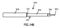
図13Aから13Dは、本発明のサイクル式アパーチャ流量調整器システムを備えるかん流−吸引手術用ハンドピース970における使用のための、本発明の一実施形態を示す。近位筐体976は、少なくとも、流量制御動作に必要なアクチュエータ部分62に適合する回転および直線アクチュエータを含み、またコントローラ132(図示せず)を含んでもよい。より小さい直径の遠位筐体974は、かん流プローブ104と流体連通したかん流ライン102の遠位部分を含む。筐体974はまた、内蔵された「管内」流量調整弁部分520を有する軸管522を含む。吸引ポート978を有する吸引プローブ972は、管522の遠位端に結合される。第1の流体経路110は、プローブ972の吸引ポート978と弁部分520の内側のアパーチャ200との間に適合される。本実施形態は、制御された流量での非常に高い真空の使用を可能とする利点と共に、従来のかん流/吸引ハンドピースを置き換えるために、有利に使用され得る。ハンドピース970は、追加的な水晶体破砕エネルギーの使用の大幅な低減を伴い、軟質から中程度の密度の水晶体断片を、ポート978を通して吸引することを可能にし得る。同様に、これは、例えば、水晶体を軟化するためのフェムト秒LASERの使用後に、軟化した水晶体からより効率的に水晶体断片を除去するために使用され得る。
Additional embodiment (4)
Perfusion-suction (I / A) handpiece with cycle-type aperture flow regulator system:
Figures 13A through 13D illustrate one embodiment of the present invention for use in a perfusion-aspiration surgical handpiece 970 comprising the cycle aperture flow regulator system of the present invention. The proximal housing 976 includes at least a rotary and linear actuator that matches the actuator portion 62 required for flow control operations, and may include a controller 132 (not shown). A smaller diameter distal housing 974 includes the distal portion of the perfusion line 102 in fluid communication with the perfusion probe 104. The housing 974 also includes a shaft tube 522 having a built-in “in-tube” flow regulating valve portion 520. A suction probe 972 having a suction port 978 is coupled to the distal end of tube 522. The first fluid path 110 is fitted between the suction port 978 of the probe 972 and the aperture 200 inside the valve portion 520. This embodiment can be advantageously used to replace conventional perfusion / suction handpieces with the advantage of allowing the use of very high vacuum at a controlled flow rate. Handpiece 970 may allow a soft to medium density lens fragment to be aspirated through port 978 with a significant reduction in the use of additional lens crushing energy. Similarly, it can be used to more efficiently remove lens fragments from a softened lens, for example after use of a femtosecond LASER to soften the lens.

追加の実施形態(5)
断面積RMSが固定された流量調整器システムを有するハンドピース:
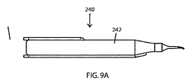
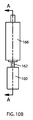
図9Aには、筐体242を有する手術用ハンドピース240の側面図が示されている。図9Bは、筐体242が取り外されたハンドピース240の内部部品を描写している。回転アクチュエータ260は、その軸の周りにシャフト280を回転させるように動作可能である。この実施形態は、室292に対するシャフト280およびロータ290の軸方向位置の調節を補助するための構造を有さない。動作中、本実施形態は、固定された軸方向位置において室292の内側のロータ290の回転をもたらし、アパーチャ200の断面積の変化のサイクルをもたらす。ロータ290の各回転サイクル中、アパーチャ200の断面積が大幅に低減または閉鎖されるサイクルの少なくとも1つの部分が存在する。本実施形態において、アパーチャ200の断面積のRMS値は、決められた通りに固定され、調節できない。本実施形態を使用する場合、吸引流量は、真空源114により提供される真空レベルを変化させることにより調節され得る。
Additional embodiments (5)
Handpiece having a flow regulator system with a fixed cross-sectional area RMS:
FIG. 9A shows a side view of a surgical handpiece 240 having a housing 242. FIG. 9B depicts the internal parts of the handpiece 240 with the housing 242 removed. The rotary actuator 260 is operable to rotate the shaft 280 about its axis. This embodiment has no structure to assist in adjusting the axial position of shaft 280 and rotor 290 relative to chamber 292. In operation, this embodiment results in a rotation of the rotor 290 inside the chamber 292 at a fixed axial position, resulting in a cycle of change in the cross-sectional area of the aperture 200. During each rotation cycle of the rotor 290, there is at least one part of the cycle in which the cross-sectional area of the aperture 200 is significantly reduced or closed. In this embodiment, the RMS value of the cross-sectional area of the aperture 200 is fixed as determined and cannot be adjusted. When using this embodiment, the suction flow rate can be adjusted by changing the vacuum level provided by the vacuum source 114.

図9Aおよび9Bに示される実施形態の変形例を図9Cに示すが、そこでは雄ねじ山247を有するねじ258が、ハンドピース筐体242内の雌ねじ山248を通過して提供されている。ねじ258は、センサ264およびモータ260を含むアクチュエータ部分62の筐体249に内部で取り付けられる。ねじ258の回転は、モータ260の軸方向の変位をもたらし、また間接的にシャフト280およびロータ290の軸方向の変位をもたらす。操作者は、ねじ258を回転させることにより、室292の内側のロータ290の軸方向位置を手動で調節することができ、このようにしてアパーチャ200の断面積RMS値を変更することができる。この動作は、流量調整ユニット真空−流量関係を変更し、動作性能を変化させる。   A variation of the embodiment shown in FIGS. 9A and 9B is shown in FIG. 9C where a screw 258 having an external thread 247 is provided through an internal thread 248 in the handpiece housing 242. Screw 258 is internally attached to housing 249 of actuator portion 62 that includes sensor 264 and motor 260. The rotation of screw 258 results in axial displacement of motor 260 and indirectly results in axial displacement of shaft 280 and rotor 290. The operator can manually adjust the axial position of the rotor 290 inside the chamber 292 by rotating the screw 258, and thus can change the cross-sectional area RMS value of the aperture 200. This operation changes the operation performance by changing the flow rate adjustment unit vacuum-flow rate relationship.

代替の実施形態(1)
振動アクチュエータにより駆動されるサイクル式アパーチャ流量調整器システム:
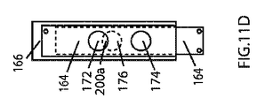
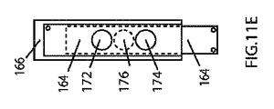
図10Aは、シャフト162により相互接続された弁部分64およびアクチュエータ部分を有する流量調整器システム60の斜視図である。本実施形態において、弁部分64は、振動運動を伝達するシャフト162を介して、単一の振動アクチュエータ160により機械的に操作される。図10Cから10Dは、図10Bからの断面図である。弁本体166は、入力ポート170および出力ポート180を有する。入力ポート170および出力ポート180は、2つの流体通路172および174を通して本体166内で流体的に接続されている。スリット178は、両方の流体通路を垂直に横切る。スリット178は、窓176を有する振動ブレード164を内部で受容する。ブレード164は、シャフト162と機械的に接続され、アクチュエータ160からの軸方向変位を受ける。シャフト162は、水密および気密シール163を有する。ブレード164における窓176は、アクチュエータ160、シャフト162およびブレード164が中央位置にある場合、ブレード164が流体通路172および174の両方を完全に消失させるように位置付けられる(図10C)。ブレード164の近位の変位をもたらすようなシャフト162に対するアクチュエータ160の操作は、窓176を流体通路174の上に位置付け、第1の流体アパーチャ200aを形成する(図10D)。ブレード164の遠位の変位をもたらすようなアクチュエータ160によるシャフト162に対する操作は、窓176を流体通路172の上に位置付け、第2の流体アパーチャ200bを形成する(図10E)。弁64の設計において「ブレークビフォーメーク(brake before make)」概念を考慮することができ、これは、1つの流体アパーチャの断面積の大幅な低減が、反対の流体アパーチャが開き始める前に生じなければならないことを意味する。図11Aから11Jに示されるように、図10Cからの中央位置の周りで振動する窓176を有するブレード164は、第1および第2の流体アパーチャ200aおよび200bの間で交代し、振動の各サイクルの間に中央位置を2回通過する。本実施形態の動作は、回転の実施形態と同様に、アクチュエータ160が、ブレード164に、一定流量および最小限のリップルを生成するのに十分に速い周波数で振動するように動力供給することにより生じる。振動の典型的な周波数は、50ヘルツ超である。本実施形態において、流速は、振動の振幅の増加がアパーチャ寸法を増加させ、その後流量を増加させるように、ブレード164の振動の振幅を変化させることにより調節され得る。流量は、アパーチャ200および201の断面積の合計のRMS値に依存する。基本実施形態と同様に、流速はまた、第2の流体経路112での真空レベルに依存する。したがって、手術用プローブ内への非閉塞流量を調整するための第2の様式は、真空を増加させて流量を増加させることである。図12におけるグラフは、1.5正弦波振動中の相に沿った全アパーチャ(アパーチャ200a+200bの合計断面積)を示す。例は、流体通路172、174および窓176に関して等しいサイズの円形開口部を有するように設計された試作弁に対応する。3つのトレースが示されている。上のトレースは、最大振動振幅に対応する。中央のトレースは、最大振幅の2/3に対応し、下のトレースは、最大振幅の1/3に対応する。水平の点線は、上のトレースにおける波形の断面積のRMS値を表す。
Alternative embodiment (1)
Cycle aperture flow regulator system driven by a vibration actuator:
FIG. 10A is a perspective view of a flow regulator system 60 having a valve portion 64 and an actuator portion interconnected by a shaft 162. In this embodiment, the valve portion 64 is mechanically operated by a single vibration actuator 160 via a shaft 162 that transmits vibrational motion. 10C to 10D are cross-sectional views from FIG. 10B. The valve body 166 has an input port 170 and an output port 180. Input port 170 and output port 180 are fluidly connected within body 166 through two fluid passages 172 and 174. A slit 178 traverses both fluid passages vertically. The slit 178 receives a vibrating blade 164 having a window 176 therein. The blade 164 is mechanically connected to the shaft 162 and receives an axial displacement from the actuator 160. The shaft 162 has a watertight and airtight seal 163. The window 176 in the blade 164 is positioned such that when the actuator 160, shaft 162, and blade 164 are in a central position, the blade 164 completely eliminates both fluid passages 172 and 174 (FIG. 10C). Actuation of the actuator 160 relative to the shaft 162 to provide proximal displacement of the blade 164 positions the window 176 over the fluid passage 174 and forms the first fluid aperture 200a (FIG. 10D). Manipulation on the shaft 162 by the actuator 160 to provide distal displacement of the blade 164 positions the window 176 over the fluid passage 172 and forms a second fluid aperture 200b (FIG. 10E). The design of the valve 64 can take into account the “break before make” concept, where a significant reduction in the cross-sectional area of one fluid aperture must occur before the opposite fluid aperture begins to open. It means you have to. As shown in FIGS. 11A through 11J, a blade 164 having a window 176 that oscillates about a central location from FIG. 10C alternates between the first and second fluid apertures 200a and 200b, and each cycle of oscillation. Pass through the central position twice. The operation of this embodiment, like the rotation embodiment, results from the actuator 160 powering the blade 164 to oscillate at a sufficiently high frequency to produce a constant flow and minimal ripple. . The typical frequency of vibration is over 50 hertz. In this embodiment, the flow rate can be adjusted by changing the vibration amplitude of the blade 164 such that increasing the vibration amplitude increases the aperture size and then increases the flow rate. The flow rate depends on the RMS value of the sum of the cross-sectional areas of the apertures 200 and 201. Similar to the basic embodiment, the flow rate also depends on the vacuum level in the second fluid path 112. Thus, a second way to adjust the non-occlusive flow into the surgical probe is to increase the flow by increasing the vacuum. The graph in FIG. 12 shows the total aperture (total cross-sectional area of the apertures 200a + 200b) along the phase during 1.5 sine wave vibration. The example corresponds to a prototype valve designed to have circular openings of equal size with respect to fluid passages 172, 174 and window 176. Three traces are shown. The upper trace corresponds to the maximum vibration amplitude. The middle trace corresponds to 2/3 of the maximum amplitude and the bottom trace corresponds to 1/3 of the maximum amplitude. The horizontal dotted line represents the RMS value of the cross-sectional area of the waveform in the upper trace.

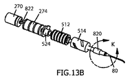
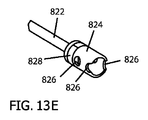
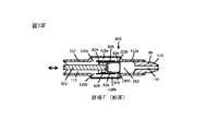
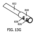
図13Aから13Fには、振動直線アクチュエータで構成されるアクチュエータ部分62を有する本発明のサイクル式アパーチャ流量調整器システム60の一実施形態を有するハンドピース800が描写されている。筐体502が取り外された図13Bに示されるハンドピース800は、単一の流量調整アクチュエータ機構としての直線アクチュエータ270を露出している。直線アクチュエータ270は、好ましくは、ボイスコイルアクチュエータである。「管内」弁部分820は、弁室292の内側の振動弁ピストン824を収容する。シャフト822は、回転安定性であり、回転なしで管522の内側で、同軸で変位する単一の自由度を有するように構成され得る。ピストン824が取り付けられたシャフト822の回転安定性は、ピストン824と室292との間の配列に寄与し得る。ピストン824は、改善された最小限の漏出のために、ピストンリング828をさらに組み込むことができる。シャフト822が軸方向中央位置にある場合、窓826と流体通路172および174の入口との間に重複が存在しないように、少なくとも1つのピストン窓826が配置される。この位置において、アパーチャ200の断面積は、大幅に低減され、流量を制限または最終的には無効化する。アクチュエータ270の動作は、窓826が交互に通路172および174の入口に重複するように、軸方向の振動運動をピストン824に伝達する直線アクチュエータ270のシャフトの振動をもたらす。この動作は、流体アパーチャ200の断面積が大幅に低減または閉鎖される中央位置を通る遷移を含む、アパーチャ200(200a+200b)の断面積の振動のサイクルをもたらす。ピストン824の振動のサイクルの周波数は、手術用プローブ80を通る実質的に一定の流量を生成するのに十分に高い周波数で動作するように、アクチュエータ270を駆動するコントローラ132により決定される。図13Cには、図13Bからの断面詳細図が示されており、部分的アパーチャ200が適合されるような位置に窓826が位置しているピストン824のスナップショット図が示されている。ピストン824の振動振幅の増加は、アパーチャ200の断面積のRMS値を増加させ、流体経路112内の所与の真空に対して流量を増加させる。振動の振幅は、コントローラ132に接続された直線運動センサ274を使用して監視され得る。好ましい実施形態と同様に、この振動形式のサイクル式アパーチャ流量調整器60は、図13Aから13Fにおいて描写されるような「管内」弁位置64、または「プローブ内」弁位置の両方で実装され得る。図13Gは、「プローブ内」振動動作のための、図13Hに示される手術用プローブ610と一致するように設計されたピストン840を示す。手術用プローブ610は、ピストン840を作用可能に受容するための一致する弁室を有するように設計される。流体通路634およびプローブ610からの流出チャネル638は、図13Gからのピストン840の窓826と連動し、弁部分64を完成させる。   13A through 13F depict a handpiece 800 having one embodiment of a cycled aperture flow regulator system 60 of the present invention having an actuator portion 62 comprised of a vibrating linear actuator. The handpiece 800 shown in FIG. 13B from which the housing 502 has been removed exposes a linear actuator 270 as a single flow adjustment actuator mechanism. The linear actuator 270 is preferably a voice coil actuator. An “in-tube” valve portion 820 houses a vibrating valve piston 824 inside the valve chamber 292. The shaft 822 may be configured to be rotationally stable and have a single degree of freedom to be coaxially displaced inside the tube 522 without rotation. The rotational stability of the shaft 822 to which the piston 824 is attached can contribute to the alignment between the piston 824 and the chamber 292. The piston 824 can further incorporate a piston ring 828 for improved minimal leakage. When the shaft 822 is in the axial center position, at least one piston window 826 is positioned such that there is no overlap between the window 826 and the inlets of the fluid passages 172 and 174. In this position, the cross-sectional area of the aperture 200 is greatly reduced, limiting or ultimately negating the flow rate. Actuation of actuator 270 results in vibration of the shaft of linear actuator 270 that transmits axial vibration motion to piston 824 such that window 826 alternately overlaps the inlets of passages 172 and 174. This action results in a cycle of oscillation of the cross-sectional area of the aperture 200 (200a + 200b), including a transition through a central position where the cross-sectional area of the fluid aperture 200 is significantly reduced or closed. The frequency of the piston 824 vibration cycle is determined by the controller 132 driving the actuator 270 to operate at a sufficiently high frequency to produce a substantially constant flow rate through the surgical probe 80. FIG. 13C shows a cross-sectional detail view from FIG. 13B, showing a snapshot view of the piston 824 with the window 826 in a position such that the partial aperture 200 is fitted. Increasing the vibration amplitude of the piston 824 increases the RMS value of the cross-sectional area of the aperture 200 and increases the flow rate for a given vacuum in the fluid path 112. The amplitude of vibration can be monitored using a linear motion sensor 274 connected to the controller 132. Similar to the preferred embodiment, this oscillating cycle aperture flow regulator 60 can be implemented in both an “in-tube” valve position 64 as depicted in FIGS. 13A through 13F, or an “in-probe” valve position. . FIG. 13G shows a piston 840 designed to coincide with the surgical probe 610 shown in FIG. 13H for “in-probe” vibration operation. Surgical probe 610 is designed to have a matching valve chamber for operatively receiving piston 840. The fluid passage 634 and the outflow channel 638 from the probe 610 interact with the window 826 of the piston 840 from FIG. 13G to complete the valve portion 64.

代替の実施形態(2)
独立型流量調整器システム実施形態:
好ましい実施形態において説明されるサイクル式アパーチャ流量調整器システムは、手術コンソール150に配置された流量調整器コントローラ132により駆動されるセンサおよびアクチュエータを有するアクチュエータ部分62を有する。この動作モードは、複数の変数を統合してシステム動作を改善することを可能にするが、本発明の実施のための厳密な要件ではない。プロセッサおよびデータ保存メモリを含むコントローラ132は、アクチュエータ部分62を含む同じユニット内に組み込まれ、最終的には独立モードで動作するためにDC電源等の外部電力のみを必要とし得る。フットペダル152等のユーザインターフェースは、操作者が動作を命令するために、この独立型流量調整器システムユニットに直接接続され得る。ユニットは、さらに、第2の流体経路112に流体接続され、例えば流量調整器システム60の弁部分64内に配置され、動作の改善された制御のためにコントローラ132に接続された、真空センサ140を組み込んでもよい。流量制御システム60は、手術用ハンドピースとは独立して動作することができ、手術用ハンドピースと真空源との間の吸引経路内にインラインで配置され得る。
Alternative embodiment (2)
Independent flow regulator system embodiment:
The cycled aperture flow regulator system described in the preferred embodiment has an actuator portion 62 having sensors and actuators driven by a flow regulator controller 132 located at the surgical console 150. This mode of operation allows multiple variables to be integrated to improve system operation, but is not a strict requirement for the practice of the present invention. A controller 132 that includes a processor and data storage memory is incorporated into the same unit that includes the actuator portion 62 and may ultimately require only external power, such as a DC power source, to operate in an independent mode. A user interface, such as a foot pedal 152, can be directly connected to this stand-alone flow regulator system unit for an operator to command actions. The unit is further fluidly connected to the second fluid path 112, eg, located in the valve portion 64 of the flow regulator system 60, and connected to the controller 132 for improved control of operation, the vacuum sensor 140. May be incorporated. The flow control system 60 can operate independently of the surgical handpiece and can be placed in-line in the suction path between the surgical handpiece and the vacuum source.

利点:
本発明のサイクル式流量調整器システムは、調節可能な流量と共に高真空を使用した、眼の内部等の体腔からの流体および組織断片の安定した吸引を可能とする。このようにして、外科的処置は、より速く、より安全に行うことができ、超音波またはLASER等の補助的な水晶体破砕エネルギーの必要性を低減する。
advantage:
The cycle flow regulator system of the present invention allows for stable aspiration of fluids and tissue fragments from body cavities, such as the interior of the eye, using a high vacuum with an adjustable flow rate. In this way, surgical procedures can be performed faster and more safely, reducing the need for auxiliary lens crushing energy such as ultrasound or LASER.

結論、分岐および範囲:
読者には、本明細書に記載のサイクル式アパーチャ変調流量調整器システムが、流量を制御し、手術用吸引ライン内側の真空の安全な使用の範囲を増加させることによって、より効率的でより安全な外科的処置を行うことを可能とすることが分かるだろう。記載された説明は、多くの具体性を含むが、これらは、範囲に対する限定として解釈されるべきではなく、むしろそのいくつかの実施形態の例示として解釈されるべきである。多くの他の変形例が可能である。システムは、主に眼科手術用に、より具体的には、白内障等の水晶体除去手術および屈折率のための水晶体除去処置用に考えられている。手術用プローブを通して流体および組織断片を除去する必要がある他の外科的処置、例えば内視鏡関節手術が、本発明の実践から利益を受けることができる。設計は、幅広く変動し得る。例えば、弁室の内側の単一または複数のアパーチャが使用されてもよい。可変流体アパーチャに適合するように関与する流体通路の入口に、多様な形状が使用されてもよい。流体窓、ポートおよび蓋に対して異なる数および形状が組み込まれてもよい。弁構成に関与する流体チャネルは、閉鎖されても開放されてもよく、そのような場合、隣接部品により完成される。異なる種類の直線および回転アクチュエータが使用されてもよい。異なる種類の運動センサが使用されてもよく、これらは全て、本発明の範囲から逸脱せずに行うことができる。したがって、範囲は、例示された実施形態(複数を含む)によってではなく、添付の特許請求の範囲およびそれらの法的な均等物によって決定されるべきである。
Conclusion, branch and scope:
For the reader, the cycled aperture modulated flow regulator system described herein is more efficient and safer by controlling the flow rate and increasing the range of safe use of the vacuum inside the surgical suction line. It will be appreciated that it is possible to perform various surgical procedures. The description set forth includes many specificities, but these should not be construed as limitations on the scope, but rather as exemplifications of some embodiments thereof. Many other variations are possible. The system is considered primarily for ophthalmic surgery, more specifically for lens removal surgery such as cataracts and lens removal procedures for refractive index. Other surgical procedures that require the removal of fluids and tissue fragments through the surgical probe, such as endoscopic joint surgery, can benefit from the practice of the present invention. The design can vary widely. For example, single or multiple apertures inside the valve chamber may be used. A variety of shapes may be used at the inlets of the fluid passages involved to accommodate the variable fluid aperture. Different numbers and shapes may be incorporated for fluid windows, ports and lids. The fluid channels involved in the valve configuration may be closed or open, in which case they are completed by adjacent components. Different types of linear and rotary actuators may be used. Different types of motion sensors may be used, all of which can be done without departing from the scope of the present invention. Accordingly, the scope should be determined not by the illustrated embodiment (s), but by the appended claims and their legal equivalents.

60 サイクル式アパーチャ流量調整器システム
62 サイクル式アパーチャ流量調整アクチュエータ部分
64 サイクル式アパーチャ流量調整弁部分
68 組織破砕アクチュエータ
70 手術用ハンドピース
80 手術用プローブ
82 吸引ポート
84 プローブシャフト
86 プローブハブ
88 手術用プローブ取り付けねじ山
90 かん流弁
92 かん流弁信号ケーブル
100 流体源
102 かん流ライン
104 かん流プローブ
106 かん流圧力センサ
108 かん流センサケーブル
109 直接流体経路
110 第1の流体経路
111 吸引管
114 調節可能な真空源
116 流体廃棄物貯蔵部
118 真空制御弁
120 逃がし弁
130 プロセッサ
132 サイクル式アパーチャ流量調整コントローラ
134 組織破砕器駆動部
140 吸引圧力センサ
142 アクチュエータケーブル
143 流量調整器制御ケーブル
144 運動センサケーブル
146 組織破砕器駆動部ケーブル
150 水晶体切除コンソール
160 振動アクチュエータ
162 流量調整器振動シャフト
163 シール
164 振動ブレード
166 弁部分本体
170 弁入力部
172 流体通路
174 第2の流体通路
178 弁スリット
180 弁出力部
200 調節可能な断面積を有するアパーチャ
204 組織断片
206 通過する組織断片
208 保持された組織断片
240 固定アパーチャRMSハンドピース
242 ハンドピース筐体
247 雄ねじ山
248 雌ねじ山
249 アクチュエータ筐体
258 ねじ
260 回転モータ
262 回転モータシャフト
264 回転位置センサ
270 直線アクチュエータ
272 直線アクチュエータシャフト
274 軸方向位置センサ
276 同軸回転継手
280 流量調整器回転シャフト
282 軸受
284 軸受
290 弁ロータ
292 弁室
294 ロータの蓋
295 刃
296 ロータ窓
400 先行技術のハンドピース
402 ハンドピースの筐体
404 かん流管
406 吸引ラインコネクタ
500 手術用ハンドピース
502 ハンドピース筐体
504 かん流管
506 吸引管
508 かん流スリーブ
510 超音波水晶体切除プローブ
512 超音波アクチュエータ
514 超音波運動変換器
520 「管内」弁部分
522 ハンドピース軸管
523 循環空間
524 シャフトシール
525 シャフトシールカバー
526 シャフトシール本体
527 Oリング
528 バイパスチャネル
530 流体返却ポート
600 手術用ハンドピース
610 部分弁部分および2つの流体通路を有する手術用プローブ
634 流体通路
638 流出チャネル
710 部分弁部分および1つの流体通路を有する手術用プローブ
800 振動駆動サイクル式流量調整ハンドピース
820 振動「管内」弁部分
822 振動シャフト
824 「管内」弁実施形態用のピストン
826 ピストン窓
828 ピストンリング
840 「プローブ内」弁実施形態用のピストン
910 完全弁部分および1つの流体通路を有する手術用プローブ
922 シャフト遠位機能
924 手術用プローブロータ
926 ロータシャフト一致機能
928 ロータ窓
930 ばね
932 ロータ保持狭窄
950 弁および組織断片化機能を有する手術用プローブ
952 拍車状構造
954 内部組織断片化機能を有する弁ロータ
956 ロータ内の組織断片化リブ
970 流量調整器システムを有するかん流−吸引ハンドピース
972 吸引プローブ
974 I/Aハンドピース遠位筐体
976 I/Aハンドピース近位筐体
978 吸引ポート
60 Cycle Aperture Flow Regulator System 62 Cycle Aperture Flow Control Actuator Part 64 Cycle Aperture Flow Control Valve Part 68 Tissue Fracture Actuator 70 Surgical Handpiece 80 Surgical Probe 82 Suction Port 84 Probe Shaft 86 Probe Hub 88 Surgical Probe Mounting thread 90 Perfusion valve 92 Perfusion valve signal cable 100 Fluid source 102 Perfusion line 104 Perfusion probe 106 Perfusion pressure sensor 108 Perfusion sensor cable 109 Direct fluid path 110 First fluid path 111 Suction pipe 114 Adjustable Vacuum source 116 Fluid waste storage unit 118 Vacuum control valve 120 Relief valve 130 Processor 132 Cycle type aperture flow control controller 134 Tissue breaker drive unit 140 Suction Pressure sensor 142 Actuator cable 143 Flow regulator control cable 144 Motion sensor cable 146 Tissue crusher drive cable 150 Lens excision console 160 Vibration actuator 162 Flow regulator vibration shaft 163 Seal 164 Vibration blade 166 Valve part main body 170 Valve input part 172 Fluid Passage 174 Second fluid passage 178 Valve slit 180 Valve output 200 Aperture with adjustable cross-sectional area 204 Tissue fragment 206 Tissue piece passing 208 Retained tissue piece 240 Fixed aperture RMS handpiece 242 Handpiece housing 247 Male thread Mountain 248 Female thread 249 Actuator housing 258 Screw 260 Rotation motor 262 Rotation motor shaft 264 Rotation position sensor 270 Linear actuator 272 Linear actuator shaft 274 Axial position sensor 276 Coaxial rotary joint 280 Flow regulator rotary shaft 282 Bearing 284 Bearing 290 Valve rotor 292 Valve chamber 294 Rotor lid 295 Blade 296 Rotor window 400 Prior art handpiece 402 Handpiece housing 404 Perfusion tube 406 Suction line connector 500 Surgical handpiece 502 Handpiece housing 504 Perfusion tube 506 Suction tube 508 Perfusion sleeve 510 Ultrasonic lens cutting probe 512 Ultrasonic actuator 514 Ultrasonic motion transducer 520 “Intravascular” valve Portion 522 Handpiece shaft tube 523 Circulating space 524 Shaft seal 525 Shaft seal cover 526 Shaft seal body 527 O-ring 528 Bypass channel 530 Fluid return port 600 Surgical handpiece 610 Surgical probe with a partial valve portion and two fluid passages 634 Fluid passage 638 Outflow channel 710 Surgical probe with a partial valve portion and one fluid passage 800 Vibration driven cycle flow regulation handpiece 820 Vibration “In-tube” valve portion 822 Vibrating shaft 824 Piston for “in-tube” valve embodiment 826 Piston window 828 Piston ring 840 Piston for “in-probe” valve embodiment 910 Surgical probe 922 with full valve portion and one fluid passage 922 Shaft distal function 924 Surgical probe rotor 926 Rotor shaft matching function 928 Rotor window 930 Spring 932 Rotor retention stenosis 950 Surgical probe with valve and tissue fragmentation function 952 Spur structure 954 Internal tissue fragmentation Valve Rotor with Capability 956 Tissue Fragmentation Rib 970 in the Rotor Perfusion-Suction Handpiece with Flow Regulator System 972 Suction Probe 974 I / A Handpiece Distal Housing 976 I / A Handpiece Proximal Housing 978 Suction port

Claims (10)

手術用プローブの吸引開口部を通した流体および組織断片の外科的吸引の間、体腔の閉塞後の不安定性を防止するためのサイクル式アパーチャ流量調整器システムであって、
a)調節可能な断面積を有する流体アパーチャを有する流量調整弁部分であって、前記流体アパーチャは、前記手術用プローブの前記吸引開口部を真空源と接続する流体経路内に配置される、流量調整弁部分と、
b)前記流体アパーチャの前記断面積を変更するように動作可能な前記流量調整弁部分と接続されたアクチュエータ部分と、
c)前記流体アパーチャの前記断面積の変化のサイクルをもたらすように、前記アクチュエータ部分にサイクルコマンド信号を提供するコントローラであって、前記サイクルのそれぞれは、前記流体アパーチャの前記断面積が実質的に低減または前記流体アパーチャが閉鎖される少なくとも1つのセグメントを含み、前記サイクルは、前記手術用プローブの前記吸引開口部において実質的に一定である流量を生成するのに十分高い周波数で生じる、コントローラとを備え、前記流体および組織断片は、前記手術用プローブの前記吸引開口部の閉塞の解消により引き起こされる前記流体経路への流体サージにより引き起こされる、前記体腔の不安定性が発生することなく、前記流体経路に沿って前記手術用プローブを使用して前記体腔から吸引され、
前記流量調整弁部分は、弁室内で回転しかつ摺動可能に軸方向に変位可能であるように構成された弁ロータを備えており
前記流量調整弁部分は、調節可能な断面積を有する前記流体アパーチャを画成し、前記流体アパーチャは前記手術用プローブの前記吸引開口部を真空源に接続する通路に配置されており、前記流量調整弁部分は、前記流体アパーチャを画成するロータ蓋を備えており、前記弁ロータは、前記流体アパーチャの断面積を変化させるように回転中に前記弁室内を軸方向に移動させられる、サイクル式アパーチャ流量調整器システム。
A cycle aperture flow regulator system for preventing instability after occlusion of a body cavity during surgical aspiration of fluid and tissue fragments through the aspiration opening of a surgical probe, comprising:
a) a flow regulating valve portion having a fluid aperture having an adjustable cross-sectional area, wherein the fluid aperture is disposed in a fluid path connecting the suction opening of the surgical probe with a vacuum source A regulating valve part;
b) an actuator portion connected to the flow regulating valve portion operable to change the cross-sectional area of the fluid aperture;
c) a controller that provides a cycle command signal to the actuator portion to provide a cycle of change in the cross-sectional area of the fluid aperture, each of the cycles wherein the cross-sectional area of the fluid aperture is substantially A controller comprising at least one segment that is reduced or wherein the fluid aperture is closed, and wherein the cycle occurs at a frequency high enough to produce a flow rate that is substantially constant at the suction opening of the surgical probe; and The fluid and tissue fragment without the instability of the body cavity caused by a fluid surge to the fluid path caused by the removal of the obstruction of the suction opening of the surgical probe. Aspiration from the body cavity using the surgical probe along a path It is,
The flow rate adjusting valve portion includes a valve rotor configured to rotate in the valve chamber and be slidable in the axial direction ;
The flow regulating valve portion defines the fluid aperture having an adjustable cross-sectional area, the fluid aperture being disposed in a passage connecting the suction opening of the surgical probe to a vacuum source, and the flow rate The regulating valve portion includes a rotor lid that defines the fluid aperture, and the valve rotor is axially moved within the valve chamber during rotation to change a cross-sectional area of the fluid aperture. Type aperture flow regulator system.
前記体腔は、眼の内部である、請求項1に記載のサイクル式アパーチャ流量調整器システム。   The cycle type aperture flow regulator system of claim 1, wherein the body cavity is inside the eye. 前記サイクル中の前記流体アパーチャの前記断面積のRMS値は、操作者により調節可能である、請求項1に記載のサイクル式アパーチャ流量調整器システム。   The cycled aperture flow regulator system of claim 1, wherein an RMS value of the cross-sectional area of the fluid aperture during the cycle is adjustable by an operator. 前記弁ロータは、少なくとも1つの流体通路の入口が、前記サイクルのそれぞれのセグメントが流量を制限している間実質的に消失するように、前記弁室内の前記少なくとも1つの流体通路の前記入口上で回転および軸方向に変位するように操作可能である、請求項1に記載のサイクル式アパーチャ流量調整器システム。 The valve rotor is located on the inlet of the at least one fluid passage in the valve chamber such that the inlet of the at least one fluid passage substantially disappears while each segment of the cycle restricts flow. The cycle aperture flow regulator system of claim 1, wherein the cycle aperture flow regulator system is operable to rotate and displace axially. 前記流量調整弁部分は、手術用ハンドピースの吸引処理に組み込まれる、請求項1に記載のサイクル式アパーチャ流量調整器システム。   The cycle type aperture flow regulator system of claim 1, wherein the flow regulating valve portion is incorporated into a suction process for a surgical handpiece. 部分的に組み立てられる前記流量調整弁部分は、手術用プローブにより提供され、手術用ハンドピースにより提供される移動部材により操作される構造を有する、請求項1に記載のサイクル式アパーチャ流量調整器システム。   The cycle type aperture flow regulator system according to claim 1, wherein the partially assembled flow regulating valve portion has a structure provided by a surgical probe and operated by a moving member provided by a surgical handpiece. . 前記流量調整弁部分は、手術用プローブ内に組み込まれ、手術用ハンドピースにより提供される移動部材により操作される、請求項1に記載のサイクル式アパーチャ流量調整器システム。   The cycle type aperture flow regulator system of claim 1, wherein the flow regulating valve portion is incorporated into a surgical probe and operated by a moving member provided by a surgical handpiece. 前記アクチュエータ部分は、シャフトを用いて前記流量調整弁部分に機械的に接続された、回転式アクチュエータ、直線アクチュエータ、回転−直線複合アクチュエータ、回転モータ、ボイスコイルアクチュエータ、圧電アクチュエータおよび空気圧式アクチュエータからなる群から選択される少なくとも1つのアクチュエータを含む、請求項1に記載のサイクル式アパーチャ流量調整器システム。   The actuator portion is composed of a rotary actuator, a linear actuator, a combined rotary-linear actuator, a rotary motor, a voice coil actuator, a piezoelectric actuator, and a pneumatic actuator, mechanically connected to the flow regulating valve portion using a shaft. The cycled aperture flow regulator system of claim 1 including at least one actuator selected from the group. 前記アクチュエータ部分は、前記コントローラにアクチュエータ部分シャフトの位置フィードバック信号を提供するように配置される、回転式位置センサおよび直線位置センサからなる群から選択される位置センサをさらに含む、請求項1に記載のサイクル式アパーチャ流量調整器システム。   The actuator portion of claim 1, further comprising a position sensor selected from the group consisting of a rotary position sensor and a linear position sensor arranged to provide an actuator portion shaft position feedback signal to the controller. Cycle aperture flow regulator system. 前記流量調整弁部分は、前記流体経路を通した組織断片クリアランスを向上させるための組織断片化手段をさらに含む、請求項1に記載のサイクル式アパーチャ流量調整器システム。 The flow control valve portion further comprises a tissue fragmentation means for improving the tissue fragments clearance through the pre-Symbol flow pathway, cycled aperture flow regulator system according to claim 1.
JP2016517736A 2013-10-31 2014-06-16 Cycle aperture flow regulator system Active JP6574170B2 (en)

Applications Claiming Priority (3)

Application Number Priority Date Filing Date Title
US201361897827P 2013-10-31 2013-10-31
US61/897,827 2013-10-31
PCT/IB2014/062252 WO2014195927A1 (en) 2013-06-04 2014-06-16 Cyclic aperture flow regulator system

Publications (3)

Publication Number Publication Date
JP2016523130A JP2016523130A (en) 2016-08-08
JP2016523130A5 JP2016523130A5 (en) 2017-07-20
JP6574170B2 true JP6574170B2 (en) 2019-09-11

Family

ID=54545563

Family Applications (1)

Application Number Title Priority Date Filing Date
JP2016517736A Active JP6574170B2 (en) 2013-10-31 2014-06-16 Cycle aperture flow regulator system

Country Status (5)

Country Link
EP (1) EP3007660B1 (en)
JP (1) JP6574170B2 (en)
CN (1) CN105407843B (en)
CA (1) CA2911581A1 (en)
ES (1) ES2627261T3 (en)

Families Citing this family (7)

* Cited by examiner, † Cited by third party
Publication number Priority date Publication date Assignee Title
NL2019887B1 (en) * 2017-11-10 2019-05-17 Crea Ip B V Method and system for active irrigation of an ophthalmic surgical site
CN108309416B (en) * 2018-02-05 2023-11-03 威海市妇幼保健院(威海市立第二医院、威海市妇女儿童医院) Fetal head aspirator
WO2020068823A1 (en) * 2018-09-24 2020-04-02 Stryker Corporation Systems and methods for improving control responsiveness during aspiration
US20210361481A1 (en) * 2020-05-21 2021-11-25 Johnson & Johnson Surgical Vision, Inc. Phacoemulsification probe comprising magnetic sensors and/or multiple independent piezoelectric vibrators
CN112494202B (en) * 2020-11-26 2022-07-05 王小东 Posterior segment pressure adjusting device in penetrating cornea transplantation operation
CN113841590B (en) * 2021-10-27 2023-03-31 三峡大学 External patch type variable flow channel anti-blocking drip irrigation tape and anti-blocking drip irrigation method
CN115252114B (en) * 2022-07-25 2023-08-25 邦士医疗科技股份有限公司 Hemostatic electrode for turbinate

Family Cites Families (10)

* Cited by examiner, † Cited by third party
Publication number Priority date Publication date Assignee Title
US5106367A (en) * 1989-11-28 1992-04-21 Alexander Ureche Eye surgery apparatus with vacuum surge suppressor
US5569188A (en) * 1995-04-11 1996-10-29 Mackool; Richard J. Apparatus for controlling fluid flow through a surgical instrument and the temperature of an ultrasonic instrument
JP2000185092A (en) * 1998-12-24 2000-07-04 Nidek Co Ltd Perfusion suction device
US7217257B2 (en) * 2002-09-30 2007-05-15 Bausch & Lomb Incorporated Aspiration flow resistor
GB2427142B (en) * 2005-06-13 2010-10-20 Single Use Surgical Ltd Multi lumen suction irrigator
US20080125695A1 (en) * 2006-06-23 2008-05-29 Hopkins Mark A Reflux control in microsurgical system
US7819837B2 (en) * 2008-12-11 2010-10-26 Bausch & Lomb Incorporated Device for controlling flow rate of aspirated fluids
US9561129B2 (en) * 2009-01-07 2017-02-07 Rodney L. Ross Tissue removal devices, systems and methods
CA2750407C (en) * 2009-01-07 2018-12-04 Enlighten Technologies, Inc. Tissue removal devices
US20100191177A1 (en) * 2009-01-23 2010-07-29 Iscience Interventional Corporation Device for aspirating fluids

Also Published As

Publication number Publication date
EP3007660B1 (en) 2017-05-03
CN105407843B (en) 2018-11-02
CN105407843A (en) 2016-03-16
JP2016523130A (en) 2016-08-08
CA2911581A1 (en) 2014-12-11
EP3007660A1 (en) 2016-04-20
ES2627261T3 (en) 2017-07-27

Similar Documents

Publication Publication Date Title
US10398595B2 (en) Cyclic aperture flow regulator system
JP6574170B2 (en) Cycle aperture flow regulator system
AU2019201617B2 (en) Selectively moveable valve elements for aspiration and irrigation circuits
AU2006201902B2 (en) Surge-flow regulator for use in ophthalmic surgical aspiration
CA2602436C (en) The application of vacuum as a method and mechanism for controlling eye chamber stability
JP5400063B2 (en) Suction control for phacoaspirator suction device
US5562612A (en) Apparatus and method for reverse flow irrigation and aspiration of interior regions of the human eye
AU2001288949A1 (en) Surge-flow regulator for use in ophthalmic surgical aspiration
MX2008009560A (en) Microsurgical instrument.
JP2015500698A5 (en)
MX2012006880A (en) Phacoemulsification hand piece with integrated aspiration pump and cartridge.
US20210186756A1 (en) Surgical instruments for ocular surgery
RU2773370C2 (en) Selectively movable valves for aspiration and irrigation circuits
Vejarano et al. Fluidics in bimanual phaco

Legal Events

Date Code Title Description
A521 Request for written amendment filed

Free format text: JAPANESE INTERMEDIATE CODE: A523

Effective date: 20170605

A621 Written request for application examination

Free format text: JAPANESE INTERMEDIATE CODE: A621

Effective date: 20170605

A131 Notification of reasons for refusal

Free format text: JAPANESE INTERMEDIATE CODE: A131

Effective date: 20180605

A521 Request for written amendment filed

Free format text: JAPANESE INTERMEDIATE CODE: A523

Effective date: 20180810

A131 Notification of reasons for refusal

Free format text: JAPANESE INTERMEDIATE CODE: A131

Effective date: 20181120

A521 Request for written amendment filed

Free format text: JAPANESE INTERMEDIATE CODE: A523

Effective date: 20190213

TRDD Decision of grant or rejection written
A01 Written decision to grant a patent or to grant a registration (utility model)

Free format text: JAPANESE INTERMEDIATE CODE: A01

Effective date: 20190716

A61 First payment of annual fees (during grant procedure)

Free format text: JAPANESE INTERMEDIATE CODE: A61

Effective date: 20190815

R150 Certificate of patent or registration of utility model

Ref document number: 6574170

Country of ref document: JP

Free format text: JAPANESE INTERMEDIATE CODE: R150

S111 Request for change of ownership or part of ownership

Free format text: JAPANESE INTERMEDIATE CODE: R313113

R350 Written notification of registration of transfer

Free format text: JAPANESE INTERMEDIATE CODE: R350

R250 Receipt of annual fees

Free format text: JAPANESE INTERMEDIATE CODE: R250

R250 Receipt of annual fees

Free format text: JAPANESE INTERMEDIATE CODE: R250