JP6572914B2 - Rotating electrical machine rotor - Google Patents

Rotating electrical machine rotor Download PDF

Info

Publication number
JP6572914B2
JP6572914B2 JP2017002784A JP2017002784A JP6572914B2 JP 6572914 B2 JP6572914 B2 JP 6572914B2 JP 2017002784 A JP2017002784 A JP 2017002784A JP 2017002784 A JP2017002784 A JP 2017002784A JP 6572914 B2 JP6572914 B2 JP 6572914B2
Authority
JP
Japan
Prior art keywords
end plate
magnet
hole
leakage flux
axial direction
Prior art date
Legal status (The legal status is an assumption and is not a legal conclusion. Google has not performed a legal analysis and makes no representation as to the accuracy of the status listed.)
Active
Application number
JP2017002784A
Other languages
Japanese (ja)
Other versions
JP2018113782A (en
Inventor
新也 佐野
新也 佐野
Current Assignee (The listed assignees may be inaccurate. Google has not performed a legal analysis and makes no representation or warranty as to the accuracy of the list.)
Toyota Motor Corp
Original Assignee
Toyota Motor Corp
Priority date (The priority date is an assumption and is not a legal conclusion. Google has not performed a legal analysis and makes no representation as to the accuracy of the date listed.)
Filing date
Publication date
Application filed by Toyota Motor Corp filed Critical Toyota Motor Corp
Priority to JP2017002784A priority Critical patent/JP6572914B2/en
Priority to DE102017223824.0A priority patent/DE102017223824A1/en
Priority to US15/855,257 priority patent/US10404114B2/en
Priority to CN201810015209.3A priority patent/CN108306431B/en
Publication of JP2018113782A publication Critical patent/JP2018113782A/en
Application granted granted Critical
Publication of JP6572914B2 publication Critical patent/JP6572914B2/en
Active legal-status Critical Current
Anticipated expiration legal-status Critical

Links

Images

Classifications

    • HELECTRICITY
    • H02GENERATION; CONVERSION OR DISTRIBUTION OF ELECTRIC POWER
    • H02KDYNAMO-ELECTRIC MACHINES
    • H02K1/00Details of the magnetic circuit
    • H02K1/06Details of the magnetic circuit characterised by the shape, form or construction
    • H02K1/22Rotating parts of the magnetic circuit
    • H02K1/27Rotor cores with permanent magnets
    • H02K1/2706Inner rotors
    • H02K1/272Inner rotors the magnetisation axis of the magnets being perpendicular to the rotor axis
    • H02K1/274Inner rotors the magnetisation axis of the magnets being perpendicular to the rotor axis the rotor consisting of two or more circumferentially positioned magnets
    • H02K1/2753Inner rotors the magnetisation axis of the magnets being perpendicular to the rotor axis the rotor consisting of two or more circumferentially positioned magnets the rotor consisting of magnets or groups of magnets arranged with alternating polarity
    • H02K1/276Magnets embedded in the magnetic core, e.g. interior permanent magnets [IPM]
    • HELECTRICITY
    • H02GENERATION; CONVERSION OR DISTRIBUTION OF ELECTRIC POWER
    • H02KDYNAMO-ELECTRIC MACHINES
    • H02K1/00Details of the magnetic circuit
    • H02K1/02Details of the magnetic circuit characterised by the magnetic material
    • HELECTRICITY
    • H02GENERATION; CONVERSION OR DISTRIBUTION OF ELECTRIC POWER
    • H02KDYNAMO-ELECTRIC MACHINES
    • H02K1/00Details of the magnetic circuit
    • H02K1/06Details of the magnetic circuit characterised by the shape, form or construction
    • H02K1/22Rotating parts of the magnetic circuit
    • H02K1/27Rotor cores with permanent magnets
    • H02K1/2706Inner rotors
    • H02K1/272Inner rotors the magnetisation axis of the magnets being perpendicular to the rotor axis
    • H02K1/274Inner rotors the magnetisation axis of the magnets being perpendicular to the rotor axis the rotor consisting of two or more circumferentially positioned magnets
    • H02K1/2753Inner rotors the magnetisation axis of the magnets being perpendicular to the rotor axis the rotor consisting of two or more circumferentially positioned magnets the rotor consisting of magnets or groups of magnets arranged with alternating polarity
    • H02K1/276Magnets embedded in the magnetic core, e.g. interior permanent magnets [IPM]
    • H02K1/2766Magnets embedded in the magnetic core, e.g. interior permanent magnets [IPM] having a flux concentration effect

Description

本発明は、ロータコアと、ロータコアの磁石孔に挿入された磁石と、エンドプレートとを備える回転電機ロータに関する。   The present invention relates to a rotating electrical machine rotor including a rotor core, a magnet inserted into a magnet hole of the rotor core, and an end plate.

従来から回転電機を構成する回転電機ロータにおいて、ロータコアの磁石孔に磁石を挿入しロータコアに磁石を固定した構成が知られている。   Conventionally, in a rotating electrical machine rotor constituting a rotating electrical machine, a configuration in which a magnet is inserted into a magnet hole of a rotor core and a magnet is fixed to the rotor core is known.

特許文献1には、複数の電磁鋼板を積層することによりロータコアを形成し、そのロータコアの複数位置に形成した軸方向の孔(磁石孔)に永久磁石である磁石を挿入した構成が記載されている。上記の構成では、ロータコアの軸方向両端にエンドプレートを配置している。エンドプレートは、ロータコアからの磁石の軸方向への飛び出しを防止する機能を有する。エンドプレートは、アルミニウム、アルミ合金等の非磁性材料から形成される。特許文献1には、エンドプレートを非磁性材料から形成することにより、磁石の軸方向端部における磁束の漏れを有効に抑制できることが記載されている。   Patent Document 1 describes a configuration in which a rotor core is formed by stacking a plurality of electromagnetic steel plates, and magnets that are permanent magnets are inserted into axial holes (magnet holes) formed at a plurality of positions of the rotor core. Yes. In said structure, the end plate is arrange | positioned at the axial direction both ends of the rotor core. The end plate has a function of preventing the magnet from jumping out from the rotor core in the axial direction. The end plate is formed from a nonmagnetic material such as aluminum or an aluminum alloy. Patent Document 1 describes that leakage of magnetic flux at the axial end of a magnet can be effectively suppressed by forming the end plate from a nonmagnetic material.

特開2013−55775号公報JP2013-55775A

特許文献1に記載された構成のように、エンドプレートに非磁性材料を用いる場合には、製造コストが上昇しやすい。一方、エンドプレートとして、ロータコアを構成する鋼板と同じ材料の鋼板により形成することにより、製造コストの上昇を抑制することが考えられる。しかしながら、単純にこのような鋼板でエンドプレートを形成する場合には、磁石から出た磁束がステータに向かわずにエンドプレート側に漏れ出る現象である磁束漏れを生じやすい。この磁束漏れが生じると、磁石から出た磁束がエンドプレートを介して短絡する磁束短絡が発生する可能性がある。磁束漏れ及び磁束短絡が発生することは、回転電機のトルクに寄与する磁束が減少し、かつ、損失が増大する原因となるので望ましくない。エンドプレートに磁石を対向させない構成では磁束漏れが発生しにくくなるが、その場合にはロータコアの孔内からの磁石の飛び出しを抑制できない。   As in the configuration described in Patent Document 1, when a nonmagnetic material is used for the end plate, the manufacturing cost tends to increase. On the other hand, it is conceivable to suppress an increase in manufacturing cost by forming the end plate with a steel plate made of the same material as the steel plate constituting the rotor core. However, when the end plate is simply formed of such a steel plate, magnetic flux leakage, which is a phenomenon in which the magnetic flux emitted from the magnet leaks toward the end plate without going to the stator, is likely to occur. When this magnetic flux leakage occurs, there is a possibility that a magnetic flux short circuit occurs in which the magnetic flux emitted from the magnet is short-circuited through the end plate. The occurrence of magnetic flux leakage and magnetic flux short circuit is undesirable because it causes a decrease in magnetic flux contributing to the torque of the rotating electrical machine and an increase in loss. In the configuration in which the magnet is not opposed to the end plate, magnetic flux leakage is less likely to occur, but in this case, the magnet cannot be prevented from jumping out of the hole in the rotor core.

本発明の回転電機ロータは、製造コストを抑制し、かつ、磁石の磁束漏れを抑制するとともに磁石の飛び出し防止性能を高くすることを目的とする。   An object of the rotating electrical machine rotor of the present invention is to suppress the manufacturing cost, suppress the magnetic flux leakage of the magnet, and increase the performance of preventing the magnet from jumping out.

本発明の回転電機ロータは、複数のコア用鋼板を積層することにより形成されたロータコアであって、軸方向に伸びる磁石孔が形成されたロータコアと、前記磁石孔に挿入された磁石と、前記ロータコアの軸方向端面に対向して配置され、第1鋼板により形成される第1エンドプレートと、前記第1エンドプレートの外側に積層され、第2鋼板により形成される第2エンドプレートと、を備え、前記コア用鋼板、前記第1鋼板及び前記第2鋼板は、材料が同じであり、前記第1エンドプレートには少なくとも1つの第1漏れ磁束抑制孔が形成され、かつ、前記第1エンドプレートは、前記磁石孔内の前記磁石の軸方向端面を覆い、前記第2エンドプレートには少なくとも1つの第2漏れ磁束抑制孔が形成され、軸方向一方側から見た場合において、前記第1漏れ磁束抑制孔及び前記第2漏れ磁束抑制孔は、前記磁石孔内の前記磁石の軸方向端面と重畳し、軸方向一方側から見た場合において、前記第1漏れ磁束抑制孔及び前記第2漏れ磁束抑制孔のそれぞれの少なくとも一部は異なる位置に配置される、回転電機ロータである。 The rotating electrical machine rotor of the present invention is a rotor core formed by laminating a plurality of core steel plates, a rotor core formed with a magnet hole extending in the axial direction, a magnet inserted into the magnet hole, A first end plate disposed opposite to the axial end surface of the rotor core and formed of a first steel plate; and a second end plate stacked on the outside of the first end plate and formed of a second steel plate. The core steel plate, the first steel plate, and the second steel plate are made of the same material, and the first end plate has at least one first leakage magnetic flux suppression hole, and the first end. The plate covers the end face of the magnet in the magnet hole in the axial direction, and the second end plate has at least one second leakage flux suppressing hole formed when viewed from one side in the axial direction. The first leakage flux suppression hole and the second leakage flux suppression hole overlap the axial end surface of the magnet in the magnet hole, and when viewed from one axial direction, the first leakage flux suppression hole At least a part of each of the hole and the second leakage flux suppressing hole is a rotating electrical machine rotor arranged at a different position.

本発明によれば、第1エンドプレート及び第2エンドプレートが、ロータコアの鋼板と同じ材料の鋼板で形成されるので、製造コストの上昇を抑制できる。また、第1エンドプレートで磁石の軸方向端面を覆い、かつ、第1エンドプレートの第1漏れ磁束抑制孔で磁石の磁束漏れを抑制できる。また、第2エンドプレートを第1エンドプレートの外側に積層し、軸方向一方側から見た場合に第1漏れ磁束抑制孔及び第2漏れ磁束抑制孔のそれぞれの少なくとも一部は異なる位置に配置されるので、第1漏れ磁束抑制孔の少なくとも一部が塞がれ、かつ、第2漏れ磁束抑制孔により第2エンドプレートでの磁石の磁束漏れを抑制できる。また、磁石の飛び出し防止性能を高くできる。したがって、製造コストを抑制し、かつ、磁石の磁束漏れを抑制するとともに磁石の飛び出し防止性能を高くすることができる。 According to the present invention, since the first end plate and the second end plate are formed of a steel plate made of the same material as the rotor core steel plate, an increase in manufacturing cost can be suppressed. Moreover, the axial end surface of the magnet can be covered with the first end plate, and the magnetic flux leakage of the magnet can be suppressed by the first leakage magnetic flux suppression hole of the first end plate. Further, the second end plate is laminated on the outer side of the first end plate, and at least a part of each of the first leakage flux suppression hole and the second leakage flux suppression hole is arranged at a different position when viewed from one axial side. Therefore, at least a part of the first leakage flux suppressing hole is blocked, and the magnetic flux leakage of the magnet at the second end plate can be suppressed by the second leakage flux suppressing hole. In addition, the ability to prevent the magnet from jumping out can be enhanced. Therefore, it is possible to suppress the manufacturing cost, to suppress the magnetic flux leakage of the magnet, and to increase the performance of preventing the magnet from jumping out.

本発明の回転電機ロータにおいて、好ましくは、前記ロータコアにおいて、前記磁石孔の前記磁石との間隙の少なくとも一部に配置され軸方向に伸びる樹脂部を備え、軸方向一方側から見た場合において、前記第1漏れ磁束抑制孔及び前記第2漏れ磁束抑制孔は、前記樹脂部と重畳し、軸方向一方側から見た場合において、前記第1漏れ磁束抑制孔及び前記第2漏れ磁束抑制孔が前記樹脂部と重畳する部分で、前記第1漏れ磁束抑制孔及び前記第2漏れ磁束抑制孔のそれぞれの少なくとも一部は異なる位置に配置される。
In the rotating electrical machine rotor of the present invention, preferably, the rotor core includes a resin portion disposed in at least a part of the gap between the magnet hole and the magnet and extending in the axial direction, when viewed from one axial direction, The first leakage flux suppression hole and the second leakage flux suppression hole overlap with the resin portion, and when viewed from one side in the axial direction, the first leakage flux suppression hole and the second leakage flux suppression hole are At least a part of each of the first leakage magnetic flux suppression hole and the second leakage magnetic flux suppression hole is disposed at a different position in a portion overlapping with the resin portion.

この好ましい構成によれば、第1エンドプレート及び第2エンドプレートのうち、樹脂部に対向する部分を流れる漏れ磁束の抑制と、樹脂部の割れによる樹脂の飛び出しの抑制とを両立できる。   According to this preferable configuration, it is possible to achieve both suppression of leakage magnetic flux flowing through a portion facing the resin portion of the first end plate and the second end plate and suppression of resin pop-out due to cracking of the resin portion.

本発明の回転電機ロータにおいて、好ましくは、前記少なくとも1つの第1漏れ磁束抑制孔は、前記第1エンドプレートに形成された複数の第1漏れ磁束抑制孔であり、前記少なくとも1つの第2漏れ磁束抑制孔は、前記第2エンドプレートに形成された複数の第2漏れ磁束抑制孔であり、軸方向一方側から見た場合において、前記複数の第1漏れ磁束抑制孔及び前記複数の第2漏れ磁束抑制孔は、前記磁石と重畳する。   In the rotating electrical machine rotor according to the present invention, preferably, the at least one first leakage flux suppressing hole is a plurality of first leakage flux suppressing holes formed in the first end plate, and the at least one second leakage leakage hole. The magnetic flux suppression holes are a plurality of second leakage flux suppression holes formed in the second end plate, and when viewed from one side in the axial direction, the plurality of first leakage magnetic flux suppression holes and the plurality of second leakage holes. The leakage flux suppression hole overlaps with the magnet.

この好ましい構成によれば、各エンドプレートの単位面積に占める漏れ磁束抑制孔の割合を大きくし、かつ、それぞれの漏れ磁束抑制孔を小さくすることにより、漏れ磁束抑制孔の総数を多くすることができる。これにより、漏れ磁束の抑制と、磁石の飛び出し抑制とをより高度に両立できる。   According to this preferred configuration, it is possible to increase the total number of leakage flux suppression holes by increasing the ratio of leakage flux suppression holes occupying the unit area of each end plate and reducing each leakage flux suppression hole. it can. Thereby, suppression of leakage magnetic flux and suppression of magnet jumping out can be achieved at a higher level.

本発明の回転電機ロータにおいて、好ましくは、前記ロータコアにおいて、前記磁石孔の前記磁石との間隙の少なくとも一部に配置され軸方向に伸びる樹脂部を備え、前記第1エンドプレートには、複数の第3漏れ磁束抑制孔が形成され、前記第2エンドプレートには、複数の第4漏れ磁束抑制孔が形成され、軸方向一方側から見た場合において、前記複数の第3漏れ磁束抑制孔及び前記複数の第4漏れ磁束抑制孔は、前記樹脂部と重畳し、軸方向一方側から見た場合において、前記複数の第3漏れ磁束抑制孔のそれぞれは、前記複数の第4漏れ磁束抑制孔のそれぞれに対し少なくとも一部が異なる位置に配置される。   In the rotating electrical machine rotor according to the present invention, preferably, the rotor core includes a resin portion that is disposed in at least a part of a gap between the magnet hole and the magnet and extends in the axial direction, and the first end plate includes a plurality of resin portions. A third leakage flux suppression hole is formed, and a plurality of fourth leakage flux suppression holes are formed in the second end plate. When viewed from one side in the axial direction, the plurality of third leakage flux suppression holes and The plurality of fourth leakage flux suppression holes overlap with the resin portion, and when viewed from one axial side, each of the plurality of third leakage flux suppression holes is the plurality of fourth leakage flux suppression holes. At least a part of each is disposed at a different position.

この好ましい構成によれば、各エンドプレートのうち、樹脂部に対向する部分における単位面積に占める漏れ磁束抑制孔の割合を大きくし、かつ、それぞれの漏れ磁束抑制孔を小さくすることにより、漏れ磁束抑制孔の総数を多くすることができる。これにより、エンドプレートのうち、樹脂部に対向する部分を流れる漏れ磁束の抑制と、樹脂部の割れによる樹脂の飛び出しの抑制とを両立できる。   According to this preferred configuration, the leakage flux can be reduced by increasing the ratio of the leakage flux suppression hole occupying the unit area in the portion of each end plate facing the resin portion and reducing the leakage flux suppression hole. The total number of suppression holes can be increased. Thereby, suppression of the leakage magnetic flux which flows through the part which opposes a resin part among end plates, and suppression of the jumping out of resin by the crack of a resin part can be made compatible.

本発明の回転電機ロータにおいて、好ましくは、前記第1鋼板及び前記第2鋼板は同じ形状であり、前記第1エンドプレート及び前記第2エンドプレートは、互いに周方向の位相を異ならせるか、または表裏方向を逆にした状態で積層される。   In the rotating electrical machine rotor of the present invention, preferably, the first steel plate and the second steel plate have the same shape, and the first end plate and the second end plate have different circumferential phases from each other, or They are stacked with the front and back directions reversed.

この好ましい構成によれば、第1エンドプレートの第1鋼板及び第2エンドプレートの第2鋼板として同じ形状のものを用いることができるので、エンドプレートの製造コストをより低減できる。   According to this preferable structure, since the thing of the same shape can be used as the 1st steel plate of a 1st end plate, and the 2nd steel plate of a 2nd end plate, the manufacturing cost of an end plate can be reduced more.

本発明の回転電機ロータによれば、製造コストを抑制し、かつ、磁石の磁束漏れを抑制するとともに磁石の飛び出し防止性能を高くすることができる。   According to the rotating electrical machine rotor of the present invention, it is possible to suppress the manufacturing cost, suppress the magnetic flux leakage of the magnet, and increase the performance of preventing the magnet from jumping out.

本発明に係る実施形態の回転電機ロータを含む回転電機の半部断面図(a)と、(a)のA部拡大図(b)である。They are a half section sectional view (a) of a rotary electric machine including a rotary electric machine rotor of an embodiment concerning the present invention, and an A section enlarged view (b) of (a). 図1の回転電機ロータから2枚のエンドプレートを取り外してロータコア及び複数の磁石の一部を軸方向一方側から見た図である。It is the figure which removed two end plates from the rotary electric machine rotor of FIG. 1, and looked at a part of rotor core and several magnets from the axial direction one side. 図1の回転電機ロータを構成する第1エンドプレートの一部を軸方向一方側から見た図である。It is the figure which looked at a part of 1st end plate which comprises the rotary electric machine rotor of FIG. 1 from the axial direction one side. 図1の回転電機ロータの一部を軸方向一方側から見た透視図である。It is the perspective view which looked at a part of rotary electric machine rotor of FIG. 1 from the axial direction one side. 本発明に係る実施形態の回転電機ロータにおいて、磁束漏れを抑制できることを説明するための図4のB−B断面図である。FIG. 5 is a cross-sectional view taken along line BB in FIG. 4 for explaining that magnetic flux leakage can be suppressed in the rotating electrical machine rotor according to the embodiment of the present invention. 回転電機ロータの比較例において、磁束漏れが発生することを説明するための図4のB−B断面に対応する図である。FIG. 5 is a view corresponding to a BB cross section of FIG. 4 for explaining that magnetic flux leakage occurs in a comparative example of a rotating electrical machine rotor. 本発明に係る実施形態の別例において、第1エンドプレートの周方向における一部を軸方向一方側から見た図である。In the other example of embodiment which concerns on this invention, it is the figure which looked at the part in the circumferential direction of the 1st end plate from the axial direction one side. 本発明に係る実施形態の別例において、第1エンドプレートの周方向における図7とは異なる部分を軸方向一方側から見た図である。In another example of the embodiment according to the present invention, it is a view of a portion different from FIG. 7 in the circumferential direction of the first end plate as viewed from one side in the axial direction. 本発明に係る実施形態の別例の回転電機ロータにおいて、図7と周方向の位相が一致する部分を軸方向一方側から見た図である。FIG. 8 is a view of a rotating electrical machine rotor according to another example of the embodiment of the present invention, as viewed from one axial side of a portion where the circumferential phase coincides with FIG. 7. 本発明に係る実施形態の別例の回転電機ロータにおいて、図8と周方向の位相が一致する部分を軸方向一方側から見た図である。FIG. 9 is a view of a rotating electrical machine rotor according to another example of the embodiment of the present invention, as viewed from one axial side of a portion where the circumferential phase coincides with FIG. 8. 本発明に係る実施形態の別例の回転電機ロータの一部を軸方向一方側から見た図であって、図9Aに対応する図である。It is the figure which looked at part of the rotary electric machine rotor of another example of embodiment which concerns on this invention from the axial direction one side, Comprising: It is a figure corresponding to FIG. 9A. 本発明に係る実施形態の別例において、第1エンドプレートの周方向における一部を軸方向一方側から見た図である。In the other example of embodiment which concerns on this invention, it is the figure which looked at the part in the circumferential direction of the 1st end plate from the axial direction one side. 図11のC部拡大図である。It is the C section enlarged view of FIG. 本発明に係る実施形態の別例において、第1エンドプレートの周方向における図11とは異なる部分を軸方向一方側から見た図である。In another example of the embodiment according to the present invention, it is a view of a portion different from FIG. 11 in the circumferential direction of the first end plate as viewed from one side in the axial direction. 本発明に係る実施形態の別例の回転電機ロータの一部を軸方向一方側から見た図(a)と、(a)のD部拡大図(b)である。They are the figure (a) which looked at a part of the rotary electric machine rotor of another example of the embodiment concerning the present invention from the axial direction one side, and the D section enlarged drawing (b) of (a). 一般的な電磁鋼板のB−H特性と、実施形態においてピン孔間隔を所定範囲に制限したときの孔間磁束経路における電磁鋼板のB−H特性とを示す図である。It is a figure which shows the BH characteristic of a general electromagnetic steel plate, and the BH characteristic of the electromagnetic steel plate in the magnetic flux path between holes when pin hole space | interval is restrict | limited to the predetermined range in embodiment. 本発明に係る実施形態の別例において、第1エンドプレートの周方向における一部を軸方向一方側から見た図である。In the other example of embodiment which concerns on this invention, it is the figure which looked at the part in the circumferential direction of the 1st end plate from the axial direction one side. 本発明に係る実施形態の別例において、回転電機ロータから第2エンドプレートを取り外して、周方向における一部を軸方向一方側から見た透視図(a)と、(a)のE部拡大図(b)である。In another example of the embodiment according to the present invention, the second end plate is removed from the rotating electrical machine rotor, and a perspective view (a) in which a part in the circumferential direction is viewed from one side in the axial direction, and an E portion enlarged in (a). FIG. 本発明に係る実施形態の別例において、第1エンドプレートの周方向における図17とは異なる部分を軸方向一方側から見た図である。In another example of the embodiment according to the present invention, it is a view of a portion different from FIG. 17 in the circumferential direction of the first end plate as viewed from one side in the axial direction. 本発明に係る実施形態の別例の回転電機ロータの一部を軸方向一方側から見た透視図である。It is the perspective view which looked at part of the rotary electric machine rotor of another example of embodiment which concerns on this invention from the axial direction one side.

以下、図面を用いて本発明の実施形態を説明する。以下で説明する形状、材料、及び個数は、説明のための例示であって、回転電機ロータの仕様に応じて適宜変更することができる。以下ではすべての図面において同等の要素には同一の符号を付して説明する。また、本文中の説明においては、必要に応じてそれ以前に述べた符号を用いるものとする。   Hereinafter, embodiments of the present invention will be described with reference to the drawings. The shapes, materials, and numbers described below are illustrative examples, and can be changed as appropriate according to the specifications of the rotating electrical machine rotor. In the following description, identical elements are denoted by the same reference symbols in all drawings. In the description in the text, the symbols described before are used as necessary.

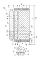
図1(a)は、実施形態の回転電機ロータ10を含む回転電機100の半部断面図であり、図1(b)は図1(a)のA部拡大図である。図2は、回転電機ロータ10から2枚のエンドプレート30、40を取り外してロータコア12及び複数の磁石16の一部を軸方向一方側から見た図である。以下では、回転電機ロータ10は、ロータ10と記載する場合がある。   FIG. 1A is a half sectional view of a rotating electrical machine 100 including the rotating electrical machine rotor 10 of the embodiment, and FIG. 1B is an enlarged view of a portion A in FIG. FIG. 2 is a view in which two end plates 30 and 40 are removed from the rotating electrical machine rotor 10 and a part of the rotor core 12 and the plurality of magnets 16 are viewed from one axial side. Below, the rotary electric machine rotor 10 may be described as the rotor 10.

ロータ10は、回転電機100を形成するために用いられる。図1を用いて回転電機100を説明する。回転電機100は、3相交流電流で駆動する永久磁石型同期電動機である。例えば、回転電機100は、ハイブリッド車両を駆動するモータとして、または、発電機として、または、その両方の機能を有するモータジェネレータとして用いられる。   The rotor 10 is used to form the rotating electrical machine 100. The rotating electrical machine 100 will be described with reference to FIG. The rotating electrical machine 100 is a permanent magnet type synchronous motor driven by a three-phase alternating current. For example, the rotating electrical machine 100 is used as a motor for driving a hybrid vehicle, a generator, or a motor generator having both functions.

回転電機100は、ステータ110と、ステータ110の半径方向内側に配置されたロータ10と、回転軸115とを備える。ステータ110は、略筒状のステータコア111と、ステータコア111の内周面から突出する複数のティース112に巻回されたステータコイル114とを含んで構成される。ステータ110は、ケース(図示せず)の内側に固定される。   The rotating electrical machine 100 includes a stator 110, a rotor 10 disposed on the radially inner side of the stator 110, and a rotating shaft 115. The stator 110 includes a substantially cylindrical stator core 111 and a stator coil 114 wound around a plurality of teeth 112 protruding from the inner peripheral surface of the stator core 111. Stator 110 is fixed inside a case (not shown).

ロータ10は、円筒状の部材であり、使用時には、回転軸115がロータ10の内側に挿入されて固定される。ロータ10は、使用時にケースの内側に配置される。ケースの内側では、ロータ10は、ステータ110の半径方向内側に対向して配置される。この状態で、回転軸115の両端部は、軸受(図示せず)によってケースに対し回転可能に支持される。ロータ10の外周面とステータ110の内周面との間には、半径方向の隙間が形成される。これによって、回転電機が形成される。以下の説明では、「半径方向」は、ロータ10の半径方向である放射方向をいい、「周方向」はロータ10の中心軸を中心とした円形に沿う方向をいう。「軸方向」は、ロータ10の中心軸に沿う方向をいう。   The rotor 10 is a cylindrical member, and the rotating shaft 115 is inserted and fixed inside the rotor 10 at the time of use. The rotor 10 is disposed inside the case when in use. Inside the case, the rotor 10 is disposed so as to face the inner side in the radial direction of the stator 110. In this state, both end portions of the rotating shaft 115 are rotatably supported with respect to the case by bearings (not shown). A radial gap is formed between the outer peripheral surface of the rotor 10 and the inner peripheral surface of the stator 110. Thereby, a rotating electrical machine is formed. In the following description, “radial direction” refers to a radial direction that is the radial direction of the rotor 10, and “circumferential direction” refers to a direction along a circle centered on the central axis of the rotor 10. “Axial direction” refers to a direction along the central axis of the rotor 10.

ロータ10は、ロータコア12と、ロータコア12の周方向複数位置に埋め込まれた永久磁石である磁石16と、軸方向両側でそれぞれ2枚のエンドプレートである第1エンドプレート30及び第2エンドプレート40とを含んでいる。具体的には、ロータコア12は、磁性材である複数の円板状のコア用鋼板13を軸方向に積層することにより形成される。ロータコア12の中心部には軸孔12aが形成され、軸孔12aの周囲であってロータ10の外周に近い領域には複数の磁石孔14が形成される。軸孔12aの内側には回転軸115が固定される。複数の磁石孔14は、ロータコア12の周方向複数位置において軸方向に伸びるように形成される。磁石孔14には磁石16が挿入されて固定される。そして、ロータコア12の両側に第1エンドプレート30及び第2エンドプレート40を積層して配置し、内側の第1エンドプレート30を磁石16と磁石16の固定のための樹脂部18a、18b(図2)とに対向させる。これにより、磁石16及び樹脂部18a、18bの軸方向への飛び出しを抑制できる。また、第1エンドプレート30のうち、磁石16と対向する部分には、後述の第1スリット32,33(図3)が形成される。さらに、第1エンドプレート30の外側に第2エンドプレート40を積層し、第2エンドプレート40に後述の第2スリット42,43(図4)が形成される。ロータコア12を軸方向一方側から見た場合に第1スリット32及び第2スリット42と、第1スリット33及び第2スリット43とは、それぞれで全部が異なる位置に配置される。これにより、エンドプレート30に非磁性材料を用いる必要がなく、磁石16の磁束漏れを抑制するとともに磁石16の飛び出し防止性能を高くすることができる。これについては後で詳しく説明する。   The rotor 10 includes a rotor core 12, a magnet 16 that is a permanent magnet embedded in a plurality of positions in the circumferential direction of the rotor core 12, and a first end plate 30 and a second end plate 40 that are two end plates on both sides in the axial direction. Including. Specifically, the rotor core 12 is formed by laminating a plurality of disk-shaped core steel plates 13 that are magnetic materials in the axial direction. A shaft hole 12 a is formed in the center of the rotor core 12, and a plurality of magnet holes 14 are formed in a region around the shaft hole 12 a and near the outer periphery of the rotor 10. A rotating shaft 115 is fixed inside the shaft hole 12a. The plurality of magnet holes 14 are formed to extend in the axial direction at a plurality of circumferential positions of the rotor core 12. A magnet 16 is inserted into the magnet hole 14 and fixed. And the 1st end plate 30 and the 2nd end plate 40 are laminated | stacked and arrange | positioned on both sides of the rotor core 12, and resin part 18a, 18b for fixing the inner side 1st end plate 30 to the magnet 16 and the magnet 16 (FIG. 2). Thereby, the magnet 16 and the resin portions 18a and 18b can be prevented from jumping out in the axial direction. Further, first slits 32 and 33 (FIG. 3) described later are formed in a portion of the first end plate 30 facing the magnet 16. Further, the second end plate 40 is laminated outside the first end plate 30, and second slits 42 and 43 (FIG. 4) to be described later are formed in the second end plate 40. When the rotor core 12 is viewed from one side in the axial direction, the first slit 32 and the second slit 42 and the first slit 33 and the second slit 43 are all arranged at different positions. Thereby, it is not necessary to use a nonmagnetic material for the end plate 30, and it is possible to suppress the magnetic flux leakage of the magnet 16 and to improve the pop-out preventing performance of the magnet 16. This will be described in detail later.

ロータコア12を構成するコア用鋼板13は、円盤形状であり、例えばケイ素電磁鋼板である。コア用鋼板13は、例えば厚みが0.5mm以下の薄板の鋼板素材を環状に打ち抜いて形成される。コア用鋼板13では、その打ち抜きによって中心部の軸孔要素13aと、その周囲の複数の磁石孔要素13bとが形成される。   The core steel plate 13 constituting the rotor core 12 has a disk shape, for example, a silicon electromagnetic steel plate. The core steel plate 13 is formed by, for example, punching a thin steel plate material having a thickness of 0.5 mm or less in an annular shape. In the core steel plate 13, the shaft hole element 13 a at the center and a plurality of magnet hole elements 13 b around it are formed by punching.

複数のコア用鋼板13の軸孔要素13aが軸方向に接続されることにより、ロータコア12の軸孔12aが形成される。複数のコア用鋼板13の複数の磁石孔要素13bが軸方向に接続されることにより、ロータコア12において、軸方向に伸びる複数の磁石孔14が形成される。   A shaft hole 12a of the rotor core 12 is formed by connecting the shaft hole elements 13a of the plurality of core steel plates 13 in the axial direction. By connecting the plurality of magnet hole elements 13 b of the plurality of core steel plates 13 in the axial direction, a plurality of magnet holes 14 extending in the axial direction are formed in the rotor core 12.

図2に示すように、ロータコア12の複数の磁石孔14は、2つを1組として、各組の磁石孔14は2つが組み合わされて半径方向外側(図2の上側)に向かって開くV字形に形成される。各磁石孔14には磁石16が挿入される。磁石16は、軸方向一方側から見た形状が長方形であり、軸方向に長尺な直方体形状である。また、磁石孔14の周方向中間部における軸方向に長尺な直方体形状の空間は、磁石が挿入される磁石挿入部分である。磁石孔14において、磁石16との間隙の少なくとも一部には軸方向に伸びた樹脂部18a、18bが配置される。具体的には、磁石孔14の磁石挿入部分に磁石16が挿入された直後において、磁石孔14の両端には空隙が形成される。そして、これらの空隙に磁石固定材である樹脂が溶融した状態で注入されて固化されることによって、軸方向に伸びた樹脂部18a、18bが配置される。これらの樹脂部18a、18bによって、ロータコア12に対し磁石16が固定される。図2では、樹脂部18a、18bを砂地で示している。   As shown in FIG. 2, the plurality of magnet holes 14 of the rotor core 12 are made into one set, and two sets of the magnet holes 14 are combined to open toward the radially outer side (upper side in FIG. 2). Formed in a letter shape. A magnet 16 is inserted into each magnet hole 14. The magnet 16 has a rectangular shape when viewed from one side in the axial direction, and has a rectangular parallelepiped shape that is long in the axial direction. Further, a rectangular parallelepiped space that is elongated in the axial direction in the circumferential intermediate portion of the magnet hole 14 is a magnet insertion portion into which a magnet is inserted. In the magnet hole 14, resin portions 18 a and 18 b extending in the axial direction are disposed in at least a part of the gap with the magnet 16. Specifically, immediately after the magnet 16 is inserted into the magnet insertion portion of the magnet hole 14, gaps are formed at both ends of the magnet hole 14. The resin portions 18a and 18b extending in the axial direction are disposed by being injected and solidified in a state in which the resin that is the magnet fixing material is melted into these gaps. The magnet 16 is fixed to the rotor core 12 by the resin portions 18a and 18b. In FIG. 2, the resin portions 18a and 18b are shown as sand.

磁石16の磁化方向は外周側面及び内周側面に対し直交する方向である。磁石孔20の空隙に注入された樹脂は、例えば加熱されることにより、磁石孔20内に磁石16が固定される。このとき、ロータコア12が加熱装置(図示せず)で加熱される。溶融状態の樹脂は加熱硬化された後、常温まで冷却されることにより上記の樹脂部18a、18bを形成する。   The magnetization direction of the magnet 16 is a direction orthogonal to the outer peripheral side surface and the inner peripheral side surface. The resin injected into the gap of the magnet hole 20 is heated, for example, so that the magnet 16 is fixed in the magnet hole 20. At this time, the rotor core 12 is heated by a heating device (not shown). The molten resin is cured by heating and then cooled to room temperature, thereby forming the resin portions 18a and 18b.

複数の磁石16は、隣り合う2つの磁石16を1組として、1組の磁石16で1つの磁極17を形成する。具体的には、1組の2つの磁石16は、複数の磁石孔14の配置にしたがって、ロータコア12の半径方向外側に向かって間隔が広がるように略V字形に対向した状態で配置される。これにより、1つの磁極17が構成される。ロータ10において、図2に示す部分では、右側の2つの磁石16からなる磁極17では、外周側面がN極であるように磁石16が磁化されており、左側の2つの磁石16からなる磁極17では、外周側面がS極であるように磁石16が磁化されている。   The plurality of magnets 16 includes two adjacent magnets 16 as one set, and one set of magnets 16 forms one magnetic pole 17. Specifically, the pair of two magnets 16 are arranged in a substantially V-shaped manner so that the interval increases toward the outside in the radial direction of the rotor core 12 according to the arrangement of the plurality of magnet holes 14. Thereby, one magnetic pole 17 is formed. In the rotor 10, in the portion shown in FIG. 2, the magnet 16 is magnetized so that the outer peripheral side surface is an N pole in the magnetic pole 17 made of the right two magnets 16, and the magnetic pole 17 made of the two left magnets 16. Then, the magnet 16 is magnetized so that the outer peripheral side surface is an S pole.

また、ロータコア12は、1組の磁石16に対応して、1つの中間ブリッジB1と、2つの外周ブリッジB2とが形成される。中間ブリッジB1は、1組の磁石16に対応して、2つの磁石孔14の互いに対向する周方向端部の間に形成された幅小磁束通路である。2つの外周ブリッジB2は、1組の磁石16に対応して、2つの磁石孔14のそれぞれの半径方向外側端部とロータコア12の外周面との間に形成された幅小磁束通路である。   The rotor core 12 is formed with one intermediate bridge B1 and two outer peripheral bridges B2 corresponding to one set of magnets 16. The intermediate bridge B <b> 1 is a narrow magnetic flux path formed between the circumferential end portions of the two magnet holes 14 facing each other corresponding to the set of magnets 16. The two outer peripheral bridges B <b> 2 are narrow magnetic flux paths formed between the radially outer ends of the two magnet holes 14 and the outer peripheral surface of the rotor core 12 corresponding to the set of magnets 16.

図1に戻って、ロータコア12の軸方向両端面にはそれぞれ第1エンドプレート30及び第2エンドプレート40が積層されて、2つずつのエンドプレート30、40によってロータコア12が挟まれる。エンドプレート30、40は、回転軸115に締め代を持って嵌合することにより固定するか、またはロータコア12に積層した状態で軸方向にかしめ治具でエンドプレートの軸方向端面を押圧してかしめ部を形成することによりロータコアに固定することができる。また、ロータコア12の軸方向両端面には第1エンドプレート30が対向して配置され、その外側に第2エンドプレート40が積層される。   Returning to FIG. 1, the first end plate 30 and the second end plate 40 are stacked on both axial end surfaces of the rotor core 12, and the rotor core 12 is sandwiched between the two end plates 30 and 40. The end plates 30 and 40 are fixed by being fitted to the rotary shaft 115 with a tightening margin, or are laminated on the rotor core 12 and pressed in the axial direction with the caulking jig in the axial direction. It can fix to a rotor core by forming a caulking part. Further, the first end plate 30 is disposed opposite to both end surfaces of the rotor core 12 in the axial direction, and the second end plate 40 is laminated on the outside thereof.

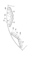
図3は、第1エンドプレート30の一部を軸方向一方側から見た図である。図4は、ロータ10の一部を軸方向一方側から見た透視図である。   FIG. 3 is a view of a part of the first end plate 30 as viewed from one axial side. FIG. 4 is a perspective view of a part of the rotor 10 as seen from one side in the axial direction.

図3を用いて第1エンドプレート30を説明する。第1エンドプレート30は、磁性材製の部材である。具体的には、第1エンドプレート30は、円盤状の第1鋼板31により形成される。第1鋼板31の中心部には、回転軸115を挿通するための軸孔31aが形成される。第1鋼板31は、ロータコア12を構成するコア用鋼板13と材料が同じで、かつ厚みが同じである。これにより後述のようにロータ10の製造コストを低減できる。   The first end plate 30 will be described with reference to FIG. The first end plate 30 is a member made of a magnetic material. Specifically, the first end plate 30 is formed by a disk-shaped first steel plate 31. A shaft hole 31 a for inserting the rotating shaft 115 is formed at the center of the first steel plate 31. The first steel plate 31 has the same material and the same thickness as the core steel plate 13 constituting the rotor core 12. Thereby, the manufacturing cost of the rotor 10 can be reduced as will be described later.

また、第1エンドプレート30において、磁石16に対向する部分には、少なくとも1つの第1漏れ磁束抑制孔が形成される。実施形態では、第1エンドプレート30には少なくとも1つの第1漏れ磁束抑制孔として、磁石16毎に1つの細長の断面矩形の孔である第1スリット32、33が、磁石16とその磁石16の両端部に位置する樹脂部18a、18bとに対向する部分に形成される。   In the first end plate 30, at least one first leakage flux suppressing hole is formed in a portion facing the magnet 16. In the embodiment, the first end plate 30 has at least one first leakage flux suppression hole, and the first slits 32 and 33 that are one elongated cross-sectional rectangular holes for each magnet 16 include the magnet 16 and the magnet 16. It is formed in the part facing resin part 18a, 18b located in the both ends.

第1スリット32,33は、第1エンドプレート30において、同じ組の磁石16で半径方向の同じ側に対向する部分に、磁石16の長手方向に沿うように形成される。これにより、1組の磁石16に対向する2つの第1スリット32、33を1組として、各組の2つの第1スリット32、33は、磁石16の配置に応じてV字形に形成される。また、周方向に隣り合う組の第1スリット32,33は、磁石16の半径方向において異なる側に対向する位置に形成される。図3では、右側の組の第1スリット32は、磁石16の半径方向内側に対向する部分に形成され、左側の組の第1スリット33は、磁石16の半径方向外側に対向する部分に形成される。各第1スリット32,33は、孔加工用のパンチ(図示せず)を用いて軸方向に打ち抜く打ち抜き加工により形成される。   The first slits 32 and 33 are formed along the longitudinal direction of the magnet 16 in the first end plate 30 at portions of the same set of magnets 16 facing the same side in the radial direction. As a result, two first slits 32, 33 facing one set of magnets 16 are taken as one set, and the two first slits 32, 33 in each set are formed in a V shape according to the arrangement of the magnets 16. . Further, the first slits 32 and 33 of the pair adjacent in the circumferential direction are formed at positions facing different sides in the radial direction of the magnet 16. In FIG. 3, the first set of slits 32 on the right side is formed in a portion facing the radially inner side of the magnet 16, and the first slit 33 of the left set is formed on a portion facing the radially outer side of the magnet 16. Is done. Each of the first slits 32 and 33 is formed by a punching process in which punching is performed in the axial direction using a punch for hole processing (not shown).

また、第1エンドプレート30は、第1スリット32,33が形成されない部分によって、磁石16の軸方向端面及び樹脂部18a、18bの軸方向端面を覆っている。例えば、第1スリット32が磁石16の半径方向内側に対向する位置に形成された部分では、第1エンドプレート30において第1スリット32に対し半径方向外側にずれた部分によって、磁石16の軸方向端面及び樹脂部18a、18bの軸方向端面が覆われる。   Further, the first end plate 30 covers the axial end surface of the magnet 16 and the axial end surfaces of the resin portions 18a and 18b by portions where the first slits 32 and 33 are not formed. For example, in the portion where the first slit 32 is formed at a position facing the radially inner side of the magnet 16, the axial direction of the magnet 16 is caused by the portion of the first end plate 30 that is displaced radially outward with respect to the first slit 32. The end faces and the axial end faces of the resin portions 18a and 18b are covered.

また、第1スリット33が磁石16の半径方向外側に対向する位置に形成された部分では、第1エンドプレート30において第1スリット33に対し半径方向内側にずれた部分によって、磁石16の軸方向端面及び樹脂部18a、18bの軸方向端面が覆われる。なお、以下では樹脂部18a、18bは総称して樹脂部18と記載する場合がある。   Further, in the portion where the first slit 33 is formed at the position facing the radially outer side of the magnet 16, the axial direction of the magnet 16 is caused by the portion of the first end plate 30 that is displaced radially inward with respect to the first slit 33. The end faces and the axial end faces of the resin portions 18a and 18b are covered. Hereinafter, the resin portions 18a and 18b may be collectively referred to as the resin portion 18.

図4に示すように、第2エンドプレート40は、磁性材製の部材である。具体的には、第2エンドプレート40は、円盤状の第2鋼板41により形成される。第2鋼板41は、ロータコア12を構成するコア用鋼板13及び第1エンドプレート30の第1鋼板31と材料が同じで、かつ厚みが同じである。これにより後述のようにロータ10の製造コストを低減できる。第2鋼板41の中心部には、回転軸115を挿通するための軸孔41aが形成される。   As shown in FIG. 4, the second end plate 40 is a member made of a magnetic material. Specifically, the second end plate 40 is formed by a disk-shaped second steel plate 41. The second steel plate 41 has the same material and the same thickness as the core steel plate 13 constituting the rotor core 12 and the first steel plate 31 of the first end plate 30. Thereby, the manufacturing cost of the rotor 10 can be reduced as will be described later. A shaft hole 41 a for inserting the rotating shaft 115 is formed at the center of the second steel plate 41.

第2エンドプレート40において、第1エンドプレート30及びロータコア12に積層した状態で、軸方向一方側から見て磁石16に重畳する位置には、少なくとも1つの第2漏れ磁束抑制孔が形成される。実施形態では、第2エンドプレート40には、少なくとも1つの第2漏れ磁束抑制孔として、磁石16毎に1つの細長の断面矩形の孔である第2スリット42、43が、磁石16とその磁石16の両端部に位置する樹脂部18とに対向する部分に形成される。図4では、第2エンドプレート40に形成され外側に見える第2スリット42,43を太線の矩形で示し、第1エンドプレート30に形成され第2エンドプレート40で隠れた内側の第1スリット32,33を細線の矩形で示している。   In the second end plate 40, at least one second leakage flux suppression hole is formed at a position overlapping with the magnet 16 when viewed from one axial direction in a state of being stacked on the first end plate 30 and the rotor core 12. . In the embodiment, the second end plate 40 includes, as at least one second leakage flux suppression hole, the second slits 42 and 43 that are one elongated cross-sectional rectangular hole for each magnet 16, and the magnet 16 and its magnet. 16 is formed in a portion facing the resin portion 18 positioned at both ends of the 16. In FIG. 4, the second slits 42 and 43 formed on the second end plate 40 and visible on the outside are indicated by bold rectangles, and the inner first slit 32 formed on the first end plate 30 and hidden by the second end plate 40 is illustrated. 33 are indicated by thin line rectangles.

本実施形態では、第1エンドプレート30を形成する第1鋼板31、及び、第2エンドプレート40を形成する第2鋼板41は同じ形状である。具体的には、第2エンドプレート40は、第1エンドプレート30と外形が同じであり、かつ、スリット42,43の形状及び形成位置も、第1エンドプレート30のスリット32,33と同じである。そして、2枚のエンドプレート30,40を積層した状態で、第2スリット42,43が第1スリット32,33に対し磁石16の半径方向において異なる側に形成されるように各エンドプレート30、40の周方向の位相を互いに異ならせる。これにより、図4のように第1エンドプレート及び第2エンドプレート40を積層した状態で、磁石16の各組に対向する位置に、磁石16の半径方向において異なる側にスリット32,33,42,43が形成される。この状態で、ロータ10を軸方向一方側から見た場合において、第1スリット32,33及び第2スリット42,43の周方向中間部は、磁石孔14内の磁石16と重畳する。また、ロータ10を軸方向一方側から見た場合において、第1スリット32,33及び第2スリット42,43の全部が異なる位置に配置される。また、ロータ10を軸方向一方側から見た場合において、第1スリット32,33及び第2スリット42,43の周方向両端部は、磁石孔14内の樹脂部18a、18bと重畳する。また、ロータ10を軸方向一方側から見た場合において、第1スリット32,33及び第2スリット42,43が樹脂部18と重畳する部分で、第1スリット32,33及び第2スリット42,43の全部が異なる位置に配置される。   In the present embodiment, the first steel plate 31 forming the first end plate 30 and the second steel plate 41 forming the second end plate 40 have the same shape. Specifically, the second end plate 40 has the same outer shape as the first end plate 30, and the shapes and positions of the slits 42 and 43 are the same as the slits 32 and 33 of the first end plate 30. is there. Then, in a state where the two end plates 30 and 40 are laminated, the end plates 30 and 40 are formed so that the second slits 42 and 43 are formed on different sides in the radial direction of the magnet 16 with respect to the first slits 32 and 33. The phases in the circumferential direction of 40 are made different from each other. Accordingly, the slits 32, 33, 42 are formed on the different sides in the radial direction of the magnet 16 at positions facing each pair of the magnets 16 in a state where the first end plate and the second end plate 40 are stacked as shown in FIG. 4. , 43 are formed. In this state, when the rotor 10 is viewed from one side in the axial direction, intermediate portions in the circumferential direction of the first slits 32 and 33 and the second slits 42 and 43 overlap with the magnet 16 in the magnet hole 14. Further, when the rotor 10 is viewed from one axial direction, the first slits 32 and 33 and the second slits 42 and 43 are all arranged at different positions. Further, when the rotor 10 is viewed from one side in the axial direction, both end portions in the circumferential direction of the first slits 32 and 33 and the second slits 42 and 43 overlap with the resin portions 18 a and 18 b in the magnet hole 14. Further, when the rotor 10 is viewed from one side in the axial direction, the first slits 32, 33 and the second slits 42, 43 overlap with the resin portion 18, and the first slits 32, 33 and the second slit 42, All 43 are arranged at different positions.

上記のロータ10によれば、磁性材製の第1エンドプレート30が磁石孔14内の磁石16に対向して第1スリット32、33が形成される。これにより、第1エンドプレート30の第1スリット32,33内に磁気抵抗が大きい空間部分が形成されることにより、エンドプレート30に磁束が流れにくくなる。このため、磁石16から第1エンドプレート30に漏れ出る磁束漏れと、第1エンドプレート30を介した磁石16の磁束短絡とを抑制できる。また、第1エンドプレート30は、磁石16の軸方向端面を覆っている。これにより、エンドプレート30に非磁性材料を用いる必要がなく、かつ、磁石16の磁束漏れの抑制と、磁石16の飛び出し抑制とを両立させることができる。   According to the rotor 10, the first slits 32 and 33 are formed so that the first end plate 30 made of a magnetic material faces the magnet 16 in the magnet hole 14. Thereby, a space portion having a large magnetic resistance is formed in the first slits 32 and 33 of the first end plate 30, so that the magnetic flux does not easily flow through the end plate 30. For this reason, magnetic flux leakage that leaks from the magnet 16 to the first end plate 30 and magnetic flux short-circuiting of the magnet 16 via the first end plate 30 can be suppressed. The first end plate 30 covers the end surface of the magnet 16 in the axial direction. Thereby, it is not necessary to use a nonmagnetic material for the end plate 30, and it is possible to achieve both suppression of magnetic flux leakage of the magnet 16 and suppression of jumping out of the magnet 16.

また、第2エンドプレート40を第1エンドプレート30の外側に積層し、軸方向一方側から見た場合に、第1スリット32,33及び第2スリット42,43の全部は異なる位置に配置される。これにより、第1スリット32,33が第2エンドプレート40で塞がれるので、磁石16の露出を抑制できる。さらに、これにより磁石16の飛び出し防止性能を高くできる。また、各エンドプレート30,40に、ロータコアを構成するコア用鋼板13と同じ材料の第1鋼板31、第2鋼板41を用いているので、製造コストの上昇を抑制できる。また、各エンドプレート30,40に、コア用鋼板13と同じ材料の第1鋼板31、第2鋼板41を用いているので、製造コストの上昇をさらに抑制できる。また、第1鋼板31及び第2鋼板41は同じ形状を用い、周方向の位相を異ならせて積層するので、製造コストの上昇をさらに抑制できる。したがって、製造コストを抑制し、かつ、磁石16の磁束漏れ及び磁束短絡を抑制するとともに磁石16の飛び出し防止性能を高くすることができる。磁束漏れ及び磁束短絡を抑制できるので、磁石16から出た多くの磁束をステータに向けて流すことができる。これにより、回転電機100でのトルク低下及び損失増加を抑制できる。   Further, when the second end plate 40 is laminated on the outside of the first end plate 30 and viewed from one axial direction, the first slits 32 and 33 and the second slits 42 and 43 are all arranged at different positions. The Thereby, since the 1st slits 32 and 33 are block | closed with the 2nd end plate 40, exposure of the magnet 16 can be suppressed. In addition, this makes it possible to improve the pop-out prevention performance of the magnet 16. Moreover, since the 1st steel plate 31 and the 2nd steel plate 41 of the same material as the steel plate 13 for cores which comprise a rotor core are used for each end plate 30 and 40, the raise of manufacturing cost can be suppressed. Moreover, since the 1st steel plate 31 and the 2nd steel plate 41 of the same material as the steel plate 13 for cores are used for each end plate 30 and 40, the raise of manufacturing cost can further be suppressed. Moreover, since the 1st steel plate 31 and the 2nd steel plate 41 use the same shape and laminate | stack by making the phase of a circumferential direction differ, the raise of manufacturing cost can further be suppressed. Therefore, it is possible to suppress the manufacturing cost, suppress the magnetic flux leakage and magnetic flux short-circuit of the magnet 16, and enhance the pop-out prevention performance of the magnet 16. Since magnetic flux leakage and magnetic flux short-circuiting can be suppressed, a large amount of magnetic flux emitted from the magnet 16 can flow toward the stator. Thereby, torque reduction and loss increase in the rotating electrical machine 100 can be suppressed.

また、ロータ10を軸方向一方側から見た場合において、第1スリット32,33及び第2スリット42,43は樹脂部18と重畳する。また、ロータ10を軸方向一方側から見た場合において、第1スリット32,33及び第2スリット42,43が樹脂部18と重畳する部分で、第1スリット32,33及び第2スリット42,43の全部が異なる位置に配置される。これにより、第1エンドプレート30及び第2エンドプレート40のうち、樹脂部18に対向する部分を流れる漏れ磁束の抑制と、樹脂部18の割れによる樹脂の飛び出しの抑制とを両立できる。   Further, when the rotor 10 is viewed from one axial direction, the first slits 32 and 33 and the second slits 42 and 43 overlap with the resin portion 18. Further, when the rotor 10 is viewed from one side in the axial direction, the first slits 32, 33 and the second slits 42, 43 overlap with the resin portion 18, and the first slits 32, 33 and the second slit 42, All 43 are arranged at different positions. As a result, it is possible to achieve both suppression of leakage magnetic flux flowing through a portion of the first end plate 30 and the second end plate 40 that faces the resin portion 18 and suppression of resin pop-out due to cracking of the resin portion 18.

樹脂部18にエンドプレート30が対向しない場合には、樹脂部18に万が一、樹脂割れが生じた場合にその一部の樹脂が外部に飛び出す可能性がある。実施形態では、樹脂割れが生じた場合でも樹脂の飛び出しを抑制できる。   If the end plate 30 does not face the resin portion 18, in the unlikely event that a resin crack occurs in the resin portion 18, a part of the resin may jump out. In the embodiment, even when a resin crack occurs, the resin can be prevented from popping out.

図5は、実施形態のロータ10において、磁束漏れを抑制できることを説明するための図4のB−B断面図である。実施形態のロータ10では、軸方向(図5の左右方向)一方側から見た場合に、第1エンドプレート30の第1スリット32と、第2エンドプレート40の第2スリット42とが異なる位置に配置される。これにより、図5に矢印αで示すように、磁石16のN極から出た磁束の一部が第1エンドプレート30側に漏れ出る傾向となった場合でも、第1スリット32の存在により、半径方向外側から半径方向内側に向かう漏れ磁束を抑制できる。このため、磁石16の磁束について第1エンドプレート30を介した磁束短絡を抑制できる。   FIG. 5 is a cross-sectional view taken along the line BB of FIG. 4 for explaining that the magnetic flux leakage can be suppressed in the rotor 10 of the embodiment. In the rotor 10 of the embodiment, the first slit 32 of the first end plate 30 and the second slit 42 of the second end plate 40 are different positions when viewed from one side in the axial direction (left-right direction in FIG. 5). Placed in. Thereby, as shown by an arrow α in FIG. 5, even when a part of the magnetic flux emitted from the N pole of the magnet 16 tends to leak to the first end plate 30 side, due to the presence of the first slit 32, Leakage magnetic flux from the radially outer side toward the radially inner side can be suppressed. For this reason, magnetic flux short-circuiting via the first end plate 30 can be suppressed for the magnetic flux of the magnet 16.

一方、図6は、比較例のロータ10aにおいて、磁束漏れが発生することを説明するための図4のB−B断面に対応する図である。図6の比較例では、第1スリット32が形成された第1エンドプレート30の外側に、第2エンドプレート40aが積層されている。第2エンドプレート40aには、中心部に回転軸115を挿通するための軸孔(図示せず)が形成されているだけであり、第2スリット42(図5)を含めて軸方向に貫通する他の貫通孔は形成されていない。このような比較例において、図6に矢印βで示すように、磁石16のN極から出た磁束の一部が第1エンドプレート30側に漏れ出る傾向となった場合を考える。この場合には、第1エンドプレート30の第1スリット32より半径方向外側で、漏れ出た磁束が、軸方向外側の第2エンドプレート40を介し第1スリット32を迂回して第1エンドプレート30の半径方向内側に向かう。これにより、磁石の磁束について第1エンドプレートを介した磁束短絡の抑制効果が低くなる。実施形態ではこのような不都合を防止できる。   On the other hand, FIG. 6 is a diagram corresponding to the BB cross section of FIG. 4 for explaining that magnetic flux leakage occurs in the rotor 10a of the comparative example. In the comparative example of FIG. 6, the second end plate 40 a is laminated outside the first end plate 30 in which the first slit 32 is formed. The second end plate 40a is only formed with a shaft hole (not shown) for inserting the rotating shaft 115 at the center, and penetrates in the axial direction including the second slit 42 (FIG. 5). No other through hole is formed. In such a comparative example, as shown by an arrow β in FIG. 6, consider a case where a part of the magnetic flux emitted from the N pole of the magnet 16 tends to leak to the first end plate 30 side. In this case, the leaked magnetic flux is radially outward from the first slit 32 of the first end plate 30 and bypasses the first slit 32 via the second end plate 40 outside in the axial direction. It goes to the inside in the radial direction of 30. Thereby, the inhibitory effect of the magnetic flux short circuit through a 1st end plate becomes low about the magnetic flux of a magnet. Such an inconvenience can be prevented in the embodiment.

なお、上記の実施形態では、ロータ10を軸方向一方側から見た場合において、第1エンドプレート30の第1スリット32,33と、第2エンドプレート40の第2スリット42,43との全部が異なる位置に配置される。一方、ロータ10を軸方向一方側から見た場合において、第1スリットと第2スリットとの一部のみが異なる位置に配置される構成としてもよい。この構成では、第1スリット及び第2スリットの残りの部分が軸方向に重畳されるので、磁石16の一部がその重畳部分を通じて外部に露出した状態となる。一方、この構成では、ロータの軸方向一方側から見て第1スリット及び第2スリットの全部が一致する場合に比べて、磁石の露出を抑制できる。これにより、この構成によっても磁石の飛び出し防止性能を高くできる。   In the above embodiment, all of the first slits 32 and 33 of the first end plate 30 and the second slits 42 and 43 of the second end plate 40 when the rotor 10 is viewed from one axial direction. Are arranged at different positions. On the other hand, when the rotor 10 is viewed from one side in the axial direction, only a part of the first slit and the second slit may be arranged at different positions. In this configuration, since the remaining portions of the first slit and the second slit are overlapped in the axial direction, a part of the magnet 16 is exposed to the outside through the overlapped portion. On the other hand, in this configuration, the exposure of the magnet can be suppressed as compared with the case where all of the first slit and the second slit match when viewed from one axial side of the rotor. Thereby, the pop-out prevention performance of the magnet can be enhanced even with this configuration.

また、上記の実施形態において、ロータ10を軸方向一方側から見た場合に、各エンドプレート30,40にスリットを、磁石16及び樹脂部18のうち、磁石16のみに重畳する部分に形成することもできる。この場合にはエンドプレートの樹脂部18に対向する部分に流れる磁束漏れの抑制効果が低くなるが、樹脂部18の飛び出しを抑制する効果を高くできる。   Further, in the above embodiment, when the rotor 10 is viewed from one side in the axial direction, slits are formed in the end plates 30 and 40 in portions of the magnet 16 and the resin portion 18 that overlap only with the magnet 16. You can also In this case, the effect of suppressing leakage of magnetic flux flowing in the portion of the end plate facing the resin portion 18 is reduced, but the effect of suppressing the jumping out of the resin portion 18 can be increased.

図7は、実施形態の別例において、第1エンドプレート30の周方向における一部を軸方向一方側から見た図である。図8は、実施形態の別例において、第1エンドプレート30の周方向における図7とは異なる部分を軸方向一方側から見た図である。図9Aは、実施形態の別例のロータ10bにおいて、図7と周方向の位相が一致する部分を軸方向一方側から見た図である。図9Bは、別例のロータ10bにおいて、図8と周方向の位相が一致する部分を軸方向一方側から見た図である。   FIG. 7 is a view of a part of the first end plate 30 in the circumferential direction as viewed from one axial direction in another example of the embodiment. FIG. 8 is a view of a portion different from FIG. 7 in the circumferential direction of the first end plate 30 as viewed from one axial direction in another example of the embodiment. FIG. 9A is a view of a portion of the rotor 10b according to another example of the embodiment, the portion of which the phase in the circumferential direction coincides with that of FIG. 7 as viewed from one side in the axial direction. FIG. 9B is a diagram of a portion of the rotor 10b according to another example, in which a phase in the circumferential direction matches that of FIG.

本例の構成では、図7に示すように、第1エンドプレート30には、軸方向一方側から見た場合に磁石16及びその両側の樹脂部18と重畳する部分に、複数の第1スリット32a、32b、33a、33bが形成される。第1スリット32a、32a、33a、33bは、同じ組の2つの磁石16において半径方向の異なる側に対向する部分に、磁石16の長手方向に沿うように形成される。第1エンドプレート30のうち、図7に示す周方向一部では、1組のスリット32a、32bについて、図7の右側の第1スリット32aは、磁石16の半径方向外側に対向する部分に形成される。図7の左側の第1スリット32bは、磁石16の半径方向内側に対向する部分に形成される。   In the configuration of this example, as shown in FIG. 7, the first end plate 30 includes a plurality of first slits in a portion overlapping the magnet 16 and the resin portions 18 on both sides when viewed from one axial direction. 32a, 32b, 33a, 33b are formed. The first slits 32 a, 32 a, 33 a, and 33 b are formed along the longitudinal direction of the magnet 16 at portions facing the different sides in the radial direction in the two magnets 16 of the same set. In a part of the first end plate 30 in the circumferential direction shown in FIG. 7, the first slit 32 a on the right side in FIG. 7 is formed in a portion facing the radially outer side of the magnet 16 with respect to the pair of slits 32 a and 32 b. Is done. The first slit 32 b on the left side in FIG. 7 is formed in a portion facing the inner side in the radial direction of the magnet 16.

一方、図8に示すように、周方向における図7とは異なる位置であって、図7の1組のスリット32a、32bと周方向に隣り合う組のスリット33a、33bのうち、図8の右側の第1スリット33aは、磁石16の半径方向内側に対向する部分に形成される。図8の左側の第1スリット33bは、磁石16の半径方向外側に対向する部分に形成される。   On the other hand, as shown in FIG. 8, it is a position different from FIG. 7 in the circumferential direction, and among the sets of slits 33a and 33b adjacent to the circumferential direction in FIG. The first slit 33 a on the right side is formed in a portion facing the inner side in the radial direction of the magnet 16. The first slit 33 b on the left side of FIG. 8 is formed in a portion facing the radially outer side of the magnet 16.

これにより、1組の磁石16に対向する2つの第1スリット32a、32b、33a、33bを1組として、各組の2つの第1スリット32a、32b、33a、33bは、磁石16の配置に応じてV字形に形成される。第1エンドプレート30において、2つの第1スリット32a、32bの組と、2つの第1スリット33a、33bの組とは、周方向に交互に配置される。   Thereby, two first slits 32a, 32b, 33a, 33b facing one set of magnets 16 are set as one set, and the two first slits 32a, 32b, 33a, 33b of each set are arranged in the arrangement of the magnets 16. Accordingly, it is formed in a V shape. In the first end plate 30, the set of two first slits 32a and 32b and the set of two first slits 33a and 33b are alternately arranged in the circumferential direction.

また、第1エンドプレート30の外側には第2エンドプレート40が積層される。図9A、図9Bに示すように、第2エンドプレート40には、軸方向一方側から見た場合に磁石16及びその両側の樹脂部18と重畳する部分に、複数の第2スリット42a、42b、43a、43bが形成される。図9A、図9Bでは、太線の矩形により第2スリット42a、42b、43a、43bを示し、細線の矩形により第1スリット32a、32b、33a、33bを示している。第2スリット42a、42b、43a、43bは、同じ組の磁石16で半径方向の異なる側に対向する部分に、磁石16の長手方向に沿うように形成される。図9Aは、第2エンドプレート40において、第1エンドプレート30の図7に示す周方向一部と位相が一致する部分を示している。図9Bは、第2エンドプレート40において、第1エンドプレート30の図8に示す周方向一部と位相が一致する部分を示している。第2エンドプレート40のうち、図9Aに示す周方向一部では、図9Aの右側の第2スリット42aが磁石16の半径方向内側に対向する部分に形成される。また、図9Aの左側の第2スリット42bが、磁石16の半径方向外側に対向する部分に形成される。   A second end plate 40 is stacked outside the first end plate 30. As shown in FIGS. 9A and 9B, the second end plate 40 includes a plurality of second slits 42a and 42b in portions overlapping with the magnet 16 and the resin portions 18 on both sides when viewed from one axial direction. , 43a, 43b are formed. 9A and 9B, the second slits 42a, 42b, 43a, and 43b are indicated by bold rectangles, and the first slits 32a, 32b, 33a, and 33b are indicated by thin rectangles. The second slits 42 a, 42 b, 43 a, 43 b are formed along the longitudinal direction of the magnet 16 in portions facing the different radial sides of the same set of magnets 16. FIG. 9A shows a portion of the second end plate 40 whose phase coincides with a part of the first end plate 30 in the circumferential direction shown in FIG. FIG. 9B shows a portion of the second end plate 40 whose phase coincides with a part of the first end plate 30 in the circumferential direction shown in FIG. In a part of the second end plate 40 in the circumferential direction shown in FIG. 9A, the second slit 42 a on the right side in FIG. 9A is formed in a portion facing the radially inner side of the magnet 16. Further, the second slit 42 b on the left side in FIG. 9A is formed in a portion facing the radially outer side of the magnet 16.

また、第2エンドプレート40のうち、図9Bに示す周方向一部では、図9Bの右側の第2スリット43aが磁石16の半径方向外側に対向する部分に形成される。また、図9Bの左側の第2スリット43bが、磁石16の半径方向内側に対向する部分に形成される。   9B, the second slit 43a on the right side in FIG. 9B is formed in a portion facing the radially outer side of the magnet 16. In the second end plate 40 shown in FIG. Further, the second slit 43 b on the left side of FIG. 9B is formed in a portion facing the inner side in the radial direction of the magnet 16.

また、ロータ10bを軸方向一方側から見た場合に、第1エンドプレート30の第1スリット32a、32b、33a、33b及び第2エンドプレート40の第2スリット42a、42b、43a、43bは磁石及び樹脂部に対向する部分で全部が一致しない。一方、図9A、図9Bの例では、中間ブリッジB1等、磁石16及び樹脂部18とは異なるロータコアの一部に対向する部分で、軸方向一方側から見た場合に第1スリット及び第2スリットの一部が重畳する。この部分で第1スリット及び第2スリットの重畳部があっても磁石及び樹脂部の飛び出し抑制には影響がない。しかもその重畳部によって磁束漏れをさらに抑制できる。   When the rotor 10b is viewed from one axial direction, the first slits 32a, 32b, 33a, 33b of the first end plate 30 and the second slits 42a, 42b, 43a, 43b of the second end plate 40 are magnets. And not all of the portions facing the resin portion match. On the other hand, in the example of FIGS. 9A and 9B, the first bridge and the second bridge when viewed from one side in the axial direction at a portion facing a part of the rotor core different from the magnet 16 and the resin portion 18 such as the intermediate bridge B1. A part of the slit overlaps. Even if there is an overlapping portion of the first slit and the second slit in this portion, there is no influence on the suppression of popping out of the magnet and the resin portion. In addition, magnetic flux leakage can be further suppressed by the overlapping portion.

また、本例の構成では、第1エンドプレート30を形成する第1鋼板31、及び、第2エンドプレート40を形成する第2鋼板41は同じ形状である。このため、第2エンドプレート40は、第1エンドプレート30と外形が同じであり、かつ、第2スリット42a、42b、43a、43bの形状及び形成位置も、第1エンドプレート30の第1スリット32a、32b、33a、33bと同じである。そして、2枚のエンドプレート30,40を積層した状態で、第2スリットが第1スリットに対し磁石16の半径方向において異なる側に形成されるように各エンドプレート30、40の周方向の位相を互いに異ならせる。   In the configuration of this example, the first steel plate 31 forming the first end plate 30 and the second steel plate 41 forming the second end plate 40 have the same shape. For this reason, the second end plate 40 has the same outer shape as the first end plate 30, and the shapes and positions of the second slits 42 a, 42 b, 43 a, 43 b are also the first slits of the first end plate 30. It is the same as 32a, 32b, 33a, 33b. Then, in the state where the two end plates 30 and 40 are stacked, the circumferential phase of each end plate 30 and 40 is formed such that the second slit is formed on a different side in the radial direction of the magnet 16 with respect to the first slit. Make them different from each other.

上記の構成の場合も、図1から図5の構成と同様の効果を得られる。その他の構成及び作用は、図1から図5の構成と同様である。   In the case of the above configuration, the same effect as the configuration of FIGS. 1 to 5 can be obtained. Other configurations and operations are the same as those in FIGS. 1 to 5.

図10は、実施形態の別例のロータ10cの一部を軸方向一方側から見た図であって、図9Aに対応する図である。本例の構成では、図7から図9Bの構成において、ロータ10cを軸方向一方側から見た場合に、磁石16毎に対応して、第1エンドプレート30の第1スリット32a、32bと第2エンドプレート40の第2スリット42a、42bとの一部を重畳させている。図10では、斜格子部により、第1スリットと第2スリットとが重畳する部分を示している。したがって、この斜格子部で、磁石16が外部に露出している。このような構成では、磁石16の一部が外部に露出した状態となるが、軸方向一方側から見て第1スリット及び第2スリットの全部が一致する構成の場合に比べて、磁石16の露出を抑制できる。また、この場合には、磁束漏れ及び磁束短絡をさらに抑制できる。その他の構成及び作用は、図7から図9Bの構成と同様である。   FIG. 10 is a view of a part of the rotor 10c of another example of the embodiment as viewed from one side in the axial direction, and corresponds to FIG. 9A. In the configuration of this example, in the configuration of FIGS. 7 to 9B, when the rotor 10c is viewed from one side in the axial direction, the first slits 32a, 32b of the first end plate 30 and the first A part of the second end plate 40 and the second slits 42a and 42b are overlapped. FIG. 10 shows a portion where the first slit and the second slit are overlapped by the oblique lattice portion. Therefore, the magnet 16 is exposed to the outside at the oblique lattice portion. In such a configuration, a part of the magnet 16 is exposed to the outside. However, the magnet 16 has a configuration in which all of the first slit and the second slit match when viewed from one side in the axial direction. Exposure can be suppressed. In this case, magnetic flux leakage and magnetic flux short circuit can be further suppressed. Other configurations and operations are the same as those in FIGS. 7 to 9B.

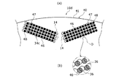
図11は、実施形態の別例において、第1エンドプレート30の周方向における一部を軸方向一方側から見た図である。図12は、図11のC部拡大図である。図13は、実施形態の別例において、第1エンドプレート30の周方向における図11とは異なる部分を軸方向一方側から見た図である。図14(a)は、実施形態の別例のロータ10dの一部を軸方向一方側から見た図であり、図14(b)は図14(a)のD部拡大図である。   FIG. 11 is a view of a part of the first end plate 30 in the circumferential direction as viewed from one axial direction in another example of the embodiment. FIG. 12 is an enlarged view of part C in FIG. FIG. 13 is a view of a portion different from FIG. 11 in the circumferential direction of the first end plate 30 as viewed from one axial direction in another example of the embodiment. FIG. 14A is a view of a part of a rotor 10d of another example of the embodiment as viewed from one side in the axial direction, and FIG. 14B is an enlarged view of a portion D of FIG. 14A.

本例の構成では、各エンドプレート30,40にスリットは形成されない。その代わりに、本例では、第1エンドプレート30において、磁石16に対向する部分には、少なくとも1つの第1漏れ磁束抑制孔として、複数の第1ピン孔36が、磁石16に対向する部分に形成される。また、第2エンドプレート40において、磁石16に対向する部分には、少なくとも1つの第2漏れ磁束抑制孔として、複数の第1ピン孔46(図14)が、磁石16に対向する部分に形成される。   In the configuration of this example, no slit is formed in each of the end plates 30 and 40. Instead, in this example, a portion of the first end plate 30 facing the magnet 16 has a plurality of first pin holes 36 facing the magnet 16 as at least one first leakage flux suppression hole. Formed. Further, in the second end plate 40, a plurality of first pin holes 46 (FIG. 14) are formed in the portion facing the magnet 16 as at least one second leakage flux suppressing hole in the portion facing the magnet 16. Is done.

具体的には、図11、図13に示すように、第1エンドプレート30の周方向複数位置には、第1V字形孔群34a及び第2V字形孔群34bが形成される。図11に示す第1V字形孔群34aは、ロータコア12のV字形の磁石孔14(図2)の配置位置に沿うように、2つのピン孔群35a、35bがV字形に配置されることにより形成される。図13に示す第2V字形孔群34bは、ロータコア12のV字形の磁石孔14の配置位置に沿うように、2つのピン孔群35c、35dがV字形に配置されることにより形成される。以下では、ピン孔群35a、35b、35c、35dは総称してピン孔群35と記載する場合がある。各ピン孔群35は、長方形領域に複数の微小な円形孔であるピン孔が整列することにより形成される。具体的には、各ピン孔群35は、複数の第1ピン孔36、複数の第2ピン孔37、及び複数の第3ピン孔38を含む。複数の第1ピン孔36は、ピン孔群35の長手方向中間部であって、第1エンドプレート30において磁石16に対向する部分に形成される。複数の第2ピン孔37は、ピン孔群35の長手方向端部であって、第1エンドプレート30において樹脂部18a、18bの少なくとも1つに対向する部分に形成される。複数の第3ピン孔38は、ピン孔群35の長手方向端部であって、第1エンドプレート30において、磁石16及び樹脂部18a、18bのいずれにも対向しない部分に形成される。実施形態では、第1ピン孔36が第1漏れ磁束抑制孔に相当し、第2ピン孔37が第3漏れ磁束抑制孔に相当する。   Specifically, as shown in FIGS. 11 and 13, a first V-shaped hole group 34 a and a second V-shaped hole group 34 b are formed at a plurality of positions in the circumferential direction of the first end plate 30. The first V-shaped hole group 34a shown in FIG. 11 is formed by arranging two pin hole groups 35a and 35b in a V-shape so as to follow the position of the V-shaped magnet hole 14 (FIG. 2) of the rotor core 12. It is formed. The second V-shaped hole group 34b shown in FIG. 13 is formed by arranging two pin hole groups 35c and 35d in a V-shape so as to follow the position where the V-shaped magnet hole 14 of the rotor core 12 is disposed. Hereinafter, the pin hole groups 35a, 35b, 35c, and 35d may be collectively referred to as the pin hole group 35. Each pin hole group 35 is formed by aligning a plurality of minute circular hole pin holes in a rectangular region. Specifically, each pin hole group 35 includes a plurality of first pin holes 36, a plurality of second pin holes 37, and a plurality of third pin holes 38. The plurality of first pin holes 36 are formed in the middle portion of the pin hole group 35 in the longitudinal direction, and are formed in a portion facing the magnet 16 in the first end plate 30. The plurality of second pin holes 37 are end portions in the longitudinal direction of the pin hole group 35, and are formed in portions of the first end plate 30 that face at least one of the resin portions 18 a and 18 b. The plurality of third pin holes 38 are end portions in the longitudinal direction of the pin hole group 35, and are formed in a portion of the first end plate 30 that does not oppose either the magnet 16 or the resin portions 18 a and 18 b. In the embodiment, the first pin hole 36 corresponds to a first leakage flux suppression hole, and the second pin hole 37 corresponds to a third leakage flux suppression hole.

ピン孔群35を構成する複数のピン孔36,37,38は、ピン孔群35の長手方向と、長手方向に対し直交する幅方向とに複数ずつが略等間隔で整列した状態で配置される。各ピン孔36,37,38は、第1エンドプレート30を軸方向に貫通し、すべてのピン孔36,37,38で同じ直径を有する。これにより、エンドプレート30の各ピン孔36,37,38を形成した部分が、網目状となっている。各ピン孔36,37,38は、エンドプレート30の複数位置を、複数の孔加工用パンチ(図示せず)で軸方向に打ち抜くことにより形成される。   The plurality of pin holes 36, 37, 38 constituting the pin hole group 35 are arranged in a state in which a plurality of pin holes 36, 37, 38 are aligned at substantially equal intervals in the longitudinal direction of the pin hole group 35 and the width direction orthogonal to the longitudinal direction. The Each pin hole 36, 37, 38 passes through the first end plate 30 in the axial direction, and all the pin holes 36, 37, 38 have the same diameter. Thereby, the part which formed each pin hole 36,37,38 of the end plate 30 is mesh shape. Each pin hole 36, 37, 38 is formed by punching a plurality of positions of the end plate 30 in the axial direction with a plurality of hole processing punches (not shown).

第1エンドプレート30において、第1V字形孔群34a及び第2V字形孔群34bは、周方向に交互に配置される。隣り合うV字形孔群34a、34bの間では、V字形孔群34a、34bの各ピン孔36,37,38における磁石孔14の長手方向についての位置が異なっている。図11の第1V字形孔群34aでは、図13の第2V字形孔群34bに比べて、磁石孔14に対し周方向一方側である長手方向一方側(図11、図13の左側)に、ピン孔の間隔の略半ピッチ分ずれている。   In the first end plate 30, the first V-shaped hole group 34a and the second V-shaped hole group 34b are alternately arranged in the circumferential direction. Between the adjacent V-shaped hole groups 34a and 34b, positions in the longitudinal direction of the magnet holes 14 in the pin holes 36, 37, and 38 of the V-shaped hole groups 34a and 34b are different. In the first V-shaped hole group 34a of FIG. 11, compared to the second V-shaped hole group 34b of FIG. 13, on one side in the longitudinal direction which is one side in the circumferential direction with respect to the magnet hole 14 (left side in FIGS. 11 and 13), The pin hole spacing is shifted by approximately half the pitch.

また、第1エンドプレート30は、各ピン孔36,37,38が形成されない部分によって、磁石16の軸方向端面及び樹脂部18a、18bの軸方向端面を覆っている。   The first end plate 30 covers the axial end surface of the magnet 16 and the axial end surfaces of the resin portions 18a and 18b by portions where the pin holes 36, 37, and 38 are not formed.

図12に示すように、ピン孔群35において、隣り合うピン孔36,37,38の間には孔間磁束経路39が形成される。孔間磁束経路39は、使用時に磁石16から第1エンドプレート30側に漏れ出た漏れ磁束が通過する可能性がある経路である。   As shown in FIG. 12, in the pin hole group 35, an inter-hole magnetic flux path 39 is formed between adjacent pin holes 36, 37, 38. The inter-hole magnetic flux path 39 is a path through which leakage magnetic flux leaked from the magnet 16 to the first end plate 30 side during use may pass.

図14に示す第2エンドプレート40にも、第1エンドプレート30と同様に、周方向複数位置には、第1V字形孔群34c及び第2V字形孔群(図示せず)が形成され、周方向において第1V字形孔群34c及び第2V字形孔群が交互に配置される。図14は、第2エンドプレート40において、第1エンドプレートの図11に示す周方向一部と周方向の位相が一致する部分を示している。第2エンドプレート40の第1V字形孔群34cは、複数の第1ピン孔46、複数の第2ピン孔47、及び複数の第3ピン孔48を含む。第1ピン孔46は、第2漏れ磁束抑制孔に相当し、第2ピン孔47は第4漏れ磁束抑制孔に相当する。図14(a)では、各ピン孔46,47,48を黒丸で示している。図14(b)では、各ピン孔46,47,48は、斜格子を付した丸で示している。   Similarly to the first end plate 30, the second end plate 40 shown in FIG. 14 is also formed with a first V-shaped hole group 34c and a second V-shaped hole group (not shown) at a plurality of positions in the circumferential direction. In the direction, the first V-shaped hole groups 34c and the second V-shaped hole groups are alternately arranged. FIG. 14 shows a portion of the second end plate 40 where the circumferential direction portion shown in FIG. 11 of the first end plate coincides with the circumferential phase. The first V-shaped hole group 34 c of the second end plate 40 includes a plurality of first pin holes 46, a plurality of second pin holes 47, and a plurality of third pin holes 48. The first pin hole 46 corresponds to a second leakage flux suppression hole, and the second pin hole 47 corresponds to a fourth leakage flux suppression hole. In FIG. 14A, each pin hole 46, 47, 48 is indicated by a black circle. In FIG. 14B, each pin hole 46, 47, 48 is indicated by a circle with a diagonal lattice.

本例の構成では、第1エンドプレート30を形成する第1鋼板31、及び、第2エンドプレート40を形成する第2鋼板41は同じ形状であり、ピン孔の形状及び形成位置も、第1鋼板31及び第2鋼板41で同じである。第2エンドプレート40において、図14に示す第1V字形孔群34cの磁石孔14に対する配置位置は、第1エンドプレート30において図13に示す第2V字形孔群34bと同じである。第2エンドプレート40において、第2V字形孔群(図示せず)の磁石孔に対する配置位置は、第1エンドプレート30において図11に示す第1V字形孔群34aと同じである。   In the configuration of this example, the first steel plate 31 that forms the first end plate 30 and the second steel plate 41 that forms the second end plate 40 have the same shape, and the shape and formation position of the pin holes are also the first. The same applies to the steel plate 31 and the second steel plate 41. In the second end plate 40, the arrangement position of the first V-shaped hole group 34c shown in FIG. 14 with respect to the magnet hole 14 is the same as that of the second V-shaped hole group 34b shown in FIG. In the second end plate 40, the arrangement position of the second V-shaped hole group (not shown) with respect to the magnet holes is the same as the first V-shaped hole group 34a shown in FIG.

そして、2枚のエンドプレート30,40を積層した状態で、互いの第1V字形孔群34a、34c及び互いの第2V字形孔群34bがそれぞれ周方向の位置が一致するように、各エンドプレート30、40の周方向の位相を互いに異ならせる。この状態で、ロータを軸方向一方側から見た場合に、V字形孔群34a、34b、34cのピン孔の形成位置が第1エンドプレート30と第2エンドプレート40とでずれる。また、ロータを軸方向一方側から見た場合において、第1エンドプレート30及び第2エンドプレート40の複数の第1ピン孔36、46は磁石16と重畳する。また、ロータを軸方向一方側から見た場合において、第1エンドプレート30の各第1ピン孔36は、第2エンドプレート40の各第1ピン孔46に対し少なくとも一部が異なる位置に配置される。   Then, in a state where the two end plates 30 and 40 are stacked, each end plate is arranged such that the positions of the first V-shaped hole groups 34a and 34c and the second V-shaped hole group 34b of each other coincide with each other in the circumferential direction. The phases in the circumferential direction of 30, 40 are made different from each other. In this state, when the rotor is viewed from one side in the axial direction, the formation positions of the pin holes of the V-shaped hole groups 34a, 34b, 34c are shifted between the first end plate 30 and the second end plate 40. Further, when the rotor is viewed from one side in the axial direction, the plurality of first pin holes 36 and 46 of the first end plate 30 and the second end plate 40 overlap with the magnet 16. Further, when the rotor is viewed from one axial side, each first pin hole 36 of the first end plate 30 is disposed at a position where at least a part thereof is different from each first pin hole 46 of the second end plate 40. Is done.

さらに、ロータを軸方向一方側から見た場合において、各エンドプレート30,40の複数の第2ピン孔37,47は樹脂部18と重畳する。また、ロータを軸方向一方側から見た場合において、第1エンドプレート30の各第2ピン孔37は、第2エンドプレート40の各第2ピン孔47に対し少なくとも一部が異なる位置に配置される。   Further, when the rotor is viewed from one side in the axial direction, the plurality of second pin holes 37 and 47 of the end plates 30 and 40 overlap with the resin portion 18. Further, when the rotor is viewed from one axial side, each second pin hole 37 of the first end plate 30 is disposed at a position at least partially different from each second pin hole 47 of the second end plate 40. Is done.

上記の構成の場合には、第1エンドプレート30に磁石16に対向して第1ピン孔36が形成されるので、第1エンドプレート30の第1ピン孔36内に磁気抵抗が大きい空間部分が形成されることにより、第1エンドプレート30に磁束が流れにくくなる。これにより、磁束漏れと磁束短絡とを抑制できる。また、第1エンドプレート30に非磁性材料を用いる必要がなく、かつ、磁石16の磁束漏れの抑制と、磁石16及び樹脂の飛び出し抑制とを両立させることができる。   In the case of the above configuration, since the first pin hole 36 is formed in the first end plate 30 so as to face the magnet 16, a space portion having a large magnetic resistance in the first pin hole 36 of the first end plate 30. Is formed, it becomes difficult for the magnetic flux to flow through the first end plate 30. Thereby, magnetic flux leakage and magnetic flux short circuit can be suppressed. Moreover, it is not necessary to use a nonmagnetic material for the first end plate 30, and it is possible to achieve both suppression of magnetic flux leakage of the magnet 16 and suppression of jumping out of the magnet 16 and the resin.

また、第1エンドプレート30において磁石16に対向する部分には、複数の第1ピン孔36が形成される。これにより、第1エンドプレート30の単位面積に占める第1ピン孔36の割合を大きくし、かつ、それぞれの第1ピン孔36を小さくすることにより、第1ピン孔36の総数を多くすることができる。このため、磁石対向部分に形成される空間部分を多くできることによる磁束漏れの抑制と、磁石16の飛び出し抑制とをより高度に両立できる。また、各第1ピン孔36は円形孔であるので、第1ピン孔36それぞれの大きさを小さくしやすい。   A plurality of first pin holes 36 are formed in a portion of the first end plate 30 that faces the magnet 16. Accordingly, the total number of the first pin holes 36 is increased by increasing the proportion of the first pin holes 36 in the unit area of the first end plate 30 and decreasing the respective first pin holes 36. Can do. For this reason, suppression of magnetic flux leakage by being able to increase the space part formed in a magnet opposing part, and suppression of the jumping-out of the magnet 16 can be made more highly compatible. Further, since each first pin hole 36 is a circular hole, the size of each first pin hole 36 can be easily reduced.

さらに、第1エンドプレート30において樹脂部18に対向する部分には、複数の第2ピン孔37が形成される。これにより、第1エンドプレート30の単位面積に占める第2ピン孔37の割合を大きくし、それぞれの第2ピン孔37を小さくすることにより、第2ピン孔37の総数を多くすることができる。このため、第1エンドプレート30のうち、樹脂部18に対向する部分を流れる漏れ磁束の抑制と、樹脂部18の割れによる樹脂の飛び出しの抑制とを両立できる。   Furthermore, a plurality of second pin holes 37 are formed in a portion of the first end plate 30 that faces the resin portion 18. Thereby, the ratio of the 2nd pin hole 37 to the unit area of the 1st end plate 30 is enlarged, and the total number of the 2nd pin holes 37 can be increased by making each 2nd pin hole 37 small. . For this reason, the suppression of the leakage magnetic flux flowing through the portion of the first end plate 30 facing the resin portion 18 and the suppression of the resin jumping out due to the crack of the resin portion 18 can be achieved.

なお、上記では、各ピン孔36,37,38,46,47,48を円形の孔とした場合を説明したが、各ピン孔は、矩形等の非円形の孔としてもよい。   In addition, although the case where each pin hole 36, 37, 38, 46, 47, 48 was made into the circular hole was demonstrated above, each pin hole is good also as non-circular holes, such as a rectangle.

また、実施形態では各エンドプレート30,40の複数のピン孔36,37,38,46,47,48について、孔間磁束経路39の幅に相当するピン孔間隔d(図12)を小さくすることができる。これにより、磁束漏れを抑制し、かつ、ステータ110(図1)を介さずに孔間磁束経路39を通って短絡する磁束短絡を抑制できる。好ましくは、ピン孔間隔dは、所定範囲である、エンドプレート30を構成する第1鋼板31の厚みの2〜6倍の範囲に制限することが好ましい。ピン孔間隔dを第1鋼板31の厚みの6倍以下に制限することにより、ピン孔36,37,38を打ち抜き加工によって形成する場合において、孔間磁束経路39におけるエンドプレート30の磁気特性を大きく低下させることができる。これにより、孔間磁束経路39に漏れ磁束が通過しにくくなるので、磁束短絡の抑制効果を高くできる。   In the embodiment, the pin hole interval d (FIG. 12) corresponding to the width of the inter-hole magnetic flux path 39 is reduced for the plurality of pin holes 36, 37, 38, 46, 47, 48 of the end plates 30, 40. be able to. Thereby, magnetic flux leakage can be suppressed, and magnetic flux short-circuiting that shorts through the inter-hole magnetic flux path 39 without passing through the stator 110 (FIG. 1) can be suppressed. Preferably, the pin hole interval d is preferably limited to a predetermined range of 2 to 6 times the thickness of the first steel plate 31 constituting the end plate 30. By limiting the pin hole interval d to 6 times or less of the thickness of the first steel plate 31, when the pin holes 36, 37, 38 are formed by punching, the magnetic characteristics of the end plate 30 in the inter-hole magnetic flux path 39 are changed. It can be greatly reduced. This makes it difficult for leakage magnetic flux to pass through the inter-hole magnetic flux path 39, so that the effect of suppressing magnetic flux short-circuiting can be enhanced.

図15は、一般的な電磁鋼板の磁場Hと磁束密度Bとの関係を表すB−H特性と、実施形態においてピン孔間隔dを上記の所定範囲に制限したときの孔間磁束経路39における電磁鋼板である第1鋼板31のB−H特性とを示す図である。図15に示すように、B−H特性は、磁場Hと、その磁場Hによって磁化される鋼板の磁束密度Bとの関係で表される。一般的な電磁鋼板のB−H特性に比べて、ピン孔間隔dを所定範囲に制限したときの実施形態におけるB−H特性では、特に磁場の小さい領域で、磁場Hの増大に対し磁束密度Bの増大が緩やかであり、透磁率が低い。これによりピン孔間隔dを所定範囲に制限することにより、磁束短絡の抑制効果を高くできることが分かる。   FIG. 15 shows the BH characteristic representing the relationship between the magnetic field H and the magnetic flux density B of a general electromagnetic steel sheet, and the inter-hole magnetic flux path 39 when the pin hole interval d is limited to the predetermined range in the embodiment. It is a figure which shows the BH characteristic of the 1st steel plate 31 which is an electromagnetic steel plate. As shown in FIG. 15, the BH characteristic is represented by the relationship between the magnetic field H and the magnetic flux density B of the steel plate magnetized by the magnetic field H. Compared with the BH characteristic of a general electromagnetic steel sheet, the BH characteristic in the embodiment when the pin hole interval d is limited to a predetermined range, the magnetic flux density with respect to the increase of the magnetic field H, particularly in a small magnetic field region. The increase in B is moderate and the magnetic permeability is low. Thus, it can be seen that the effect of suppressing the magnetic flux short circuit can be enhanced by limiting the pin hole interval d to a predetermined range.

また、上記のピン孔間隔dを第1鋼板31の厚みの2倍以上とすることにより、各ピン孔36,37,38の形状精度を十分に高くできる。上記では第1エンドプレート30を形成する第1鋼板31について説明したが、第2エンドプレート40を形成する第2鋼板41の場合も同様である。   Further, by setting the pin hole interval d to be twice or more the thickness of the first steel plate 31, the shape accuracy of the pin holes 36, 37, 38 can be sufficiently increased. Although the first steel plate 31 forming the first end plate 30 has been described above, the same applies to the second steel plate 41 forming the second end plate 40.

図16は、実施形態の別例において、第1エンドプレート30の周方向における一部を軸方向一方側から見た図である。本例の構成では、図11から図14に示した構成に比べて、第1エンドプレート30に形成された第1V字形孔群34dの各第1ピン孔36aの最大内側長さである直径を大きくしている。そして、各第2ピン孔37aの最大内側長さである直径を、各第1ピン孔36aの直径より小さくしている。図16の構成では、第3ピン孔38(図11参照)を省略しているが、第3ピン孔を形成してもよい。   FIG. 16 is a view of a part of the first end plate 30 in the circumferential direction as viewed from one axial direction in another example of the embodiment. In the configuration of this example, the diameter, which is the maximum inner length of each first pin hole 36a of the first V-shaped hole group 34d formed in the first end plate 30, as compared with the configuration shown in FIGS. It is getting bigger. And the diameter which is the maximum inner side length of each 2nd pin hole 37a is made smaller than the diameter of each 1st pin hole 36a. In the configuration of FIG. 16, the third pin hole 38 (see FIG. 11) is omitted, but a third pin hole may be formed.

また、第1エンドプレート30において、ピン孔群35e、35fの磁石孔についての長手方向L1に隣り合う第1ピン孔36aの間隔は、ピン孔群35e、35fの長手方向L1に隣り合う第2ピン孔37aの間隔より大きい。   Further, in the first end plate 30, the interval between the first pin holes 36a adjacent to the longitudinal direction L1 of the magnet holes of the pin hole groups 35e and 35f is the second adjacent to the longitudinal direction L1 of the pin hole groups 35e and 35f. It is larger than the interval between the pin holes 37a.

また、複数の第1ピン孔36aは、いわゆる千鳥状に配置される。具体的には、複数の第1ピン孔36aは、磁石16の軸方向端面に対向し、その軸方向端面の形状に沿った長方形領域(図16に斜格子で示す部分)において、長手方向L1に直線上に並んで、1つのピン孔組C1,C2,C3を形成する。そして、複数のピン孔組C1,C2,C3が長手方向L1に対し直交する方向に複数列に分かれて配置される。各ピン孔組C1,C2,C3では、複数の第1ピン孔36aがほぼ等間隔で配置される。また、複数のピン孔組C1,C2,C3は、互いに隣り合うピン孔組C1,C2,C3の間で第1ピン孔36aの長手方向L1に沿う位置がずれている。例えば、複数のピン孔組C1,C2,C3は、隣り合うピン孔組C1,C2,C3の間で、第1ピン孔36aの長手方向L1に沿う位置が略半ピッチ分ずれている。これにより複数の第1ピン孔36aが千鳥状に配置される。   The plurality of first pin holes 36a are arranged in a so-called staggered pattern. Specifically, the plurality of first pin holes 36a are opposed to the axial end surface of the magnet 16 and in a rectangular region (portion indicated by a diagonal lattice in FIG. 16) along the shape of the axial end surface in the longitudinal direction L1. Are aligned on a straight line to form one pin hole set C1, C2, C3. A plurality of pin hole sets C1, C2, C3 are arranged in a plurality of rows in a direction orthogonal to the longitudinal direction L1. In each pin hole set C1, C2, C3, a plurality of first pin holes 36a are arranged at substantially equal intervals. In addition, the positions of the plurality of pin hole sets C1, C2, and C3 along the longitudinal direction L1 of the first pin hole 36a are shifted between the adjacent pin hole sets C1, C2, and C3. For example, in the plurality of pin hole groups C1, C2, and C3, the positions along the longitudinal direction L1 of the first pin holes 36a are shifted by approximately a half pitch between the adjacent pin hole groups C1, C2, and C3. Thereby, the plurality of first pin holes 36a are arranged in a staggered manner.

また、ピン孔群35e、35fの外径側端部に位置する複数の第2ピン孔37aも、複数のピン孔組C1,C2,C3の方向に沿った複数のピン孔組D1,D2,D3に並んで配置される。また、隣り合うピン孔組D1,D2,D3の間で、第2ピン孔37aの長手方向L1に沿う位置がずれている。   In addition, the plurality of second pin holes 37a located at the outer diameter side ends of the pin hole groups 35e, 35f are also a plurality of pin hole groups D1, D2, along the direction of the plurality of pin hole groups C1, C2, C3. D3 is arranged side by side. Moreover, the position along the longitudinal direction L1 of the 2nd pin hole 37a has shifted | deviated between adjacent pin hole group D1, D2, D3.

図16では、第1エンドプレート30の周方向一部の第1V字形孔群34dを示しているが、第1V字形孔群34dと交互に形成される第2V字形孔群(図示せず)は、各ピン孔の位置が磁石孔の長手方向一方側にずれる。第2V字形孔群において、それ以外のピン孔の形状及び配置は、図16の第1V字形孔群34dと同様である。   In FIG. 16, the first V-shaped hole group 34d in the circumferential direction part of the first end plate 30 is shown, but the second V-shaped hole group (not shown) formed alternately with the first V-shaped hole group 34d is shown. The position of each pin hole is shifted to one side in the longitudinal direction of the magnet hole. In the second V-shaped hole group, the shape and arrangement of the other pin holes are the same as those of the first V-shaped hole group 34d in FIG.

また、図示を省略する第2エンドプレートにも第1エンドプレート30と同様に第1V字形孔群及び第2V字形孔群が形成される。第1エンドプレート30を形成する第1鋼板31、及び、第2エンドプレートを形成する第2鋼板は同じ形状であり、ピン孔の形状及び形成位置も、第1鋼板31及び第2鋼板で同じである。第2エンドプレートにおいて、第1V字形孔群の磁石孔に対する配置位置は、第1エンドプレート30の第2V字形孔群と同じである。第2エンドプレートにおいて、第2V字形孔群の磁石孔に対する配置位置は、第1エンドプレート30の第1V字形孔群34dと同じである。2枚のエンドプレート30を積層した状態で、互いの第1V字形孔群34d及び互いの第2V字形孔群がそれぞれ周方向の位置が一致するように、各エンドプレート30、40の周方向の位相を互いに異ならせる。   Similarly to the first end plate 30, a first V-shaped hole group and a second V-shaped hole group are also formed in the second end plate (not shown). The 1st steel plate 31 which forms the 1st end plate 30, and the 2nd steel plate which forms the 2nd end plate are the same shape, and the shape and formation position of a pin hole are also the same with the 1st steel plate 31 and the 2nd steel plate. It is. In the second end plate, the arrangement position of the first V-shaped hole group with respect to the magnet hole is the same as the second V-shaped hole group of the first end plate 30. In the second end plate, the arrangement position of the second V-shaped hole group with respect to the magnet hole is the same as that of the first V-shaped hole group 34 d of the first end plate 30. In the state where the two end plates 30 are stacked, the circumferential direction of each end plate 30, 40 is such that the first V-shaped hole group 34 d and the second V-shaped hole group of each other coincide with each other in the circumferential direction. Make the phases different from each other.

上記の構成によれば、樹脂部18の割れによる樹脂の飛び出しの抑制を図れるとともに、第1ピン孔36aの孔加工用パンチの数を抑制し、かつ、磁束漏れを抑制できる。一方、本例の構成と異なり各エンドプレート30が樹脂部18に対向しない構成では、樹脂割れが生じた場合に、樹脂の小片が磁石孔14から飛び出す可能性がある。このため、第1エンドプレート30の樹脂部18に対向する部分には、できるだけ小さい第2ピン孔37aを形成することが、樹脂の飛び出し抑制の面から好ましい。一方、磁石16が割れで飛び出す可能性は、樹脂部18の場合に比べてかなり低い。これにより、磁石16の飛び出し抑制を図る面からは、磁石16に対向する第1ピン孔36aは、磁石16の軸方向端面の形状より小さくすることを前提に、比較的大きくできる。また、第1ピン孔36aを比較的大きくできるので、磁束漏れを抑制するために必要な単位面積当たりの第1ピン孔36aが占める割合を確保しながら、第1ピン孔36aの孔加工用パンチの総数を抑制できる。これにより、各エンドプレート30の加工コストを低減しやすい。   According to the above configuration, it is possible to suppress the jumping out of the resin due to the cracking of the resin portion 18, it is possible to suppress the number of hole processing punches in the first pin hole 36 a, and to suppress magnetic flux leakage. On the other hand, unlike the configuration of this example, in a configuration in which each end plate 30 does not face the resin portion 18, there is a possibility that a small piece of resin jumps out of the magnet hole 14 when a resin crack occurs. For this reason, it is preferable to form the second pin hole 37a as small as possible in the portion facing the resin portion 18 of the first end plate 30 from the viewpoint of restraining the resin from popping out. On the other hand, the possibility of the magnet 16 jumping out due to cracking is considerably lower than that of the resin portion 18. As a result, the first pin hole 36a facing the magnet 16 can be made relatively large on the premise that the first pin hole 36a facing the magnet 16 is made smaller than the shape of the end face in the axial direction of the magnet 16 from the surface that suppresses the jump-out of the magnet 16. In addition, since the first pin hole 36a can be made relatively large, the punching hole for the first pin hole 36a is secured while ensuring the proportion of the first pin hole 36a per unit area necessary for suppressing magnetic flux leakage. Can be suppressed. Thereby, it is easy to reduce the processing cost of each end plate 30.

また、第1エンドプレート30において、ピン孔群35e、35fの磁石孔についての長手方向L1に隣り合う第1ピン孔36aの間隔が、ピン孔群35e、35fの磁石孔についての長手方向に隣り合う第2ピン孔37aの間隔より大きい。これにより、第1エンドプレート30のうち、磁石16に押される可能性がある、磁石16に対向する部分で強度を高くできるとともに、高い強度を必要としない樹脂部18に対向する部分で磁束漏れの抑制効果を高くできる。その他の構成及び作用は、図11から図15の構成と同様である。なお、エンドプレート30において、ピン孔群35e、35fの長手方向L1に対し直交する方向に隣り合う第1ピン孔36aの間隔を、ピン孔群35e、35fの長手方向L1に対し直交する方向に隣り合う第2ピン孔37aの間隔より大きくしてもよい。また、図16の構成において、各第2ピン孔37aの直径を各第1ピン孔36aの直径より小さくする構成と、第1ピン孔36aの間隔を第2ピン孔37aの間隔より大きくする構成とのうち、一方の構成のみを備えるようにすることもできる。   Further, in the first end plate 30, the interval between the first pin holes 36a adjacent to the magnet holes of the pin hole groups 35e and 35f is adjacent to the longitudinal direction of the magnet holes of the pin hole groups 35e and 35f. It is larger than the interval between the matching second pin holes 37a. As a result, the strength of the first end plate 30 that can be pushed by the magnet 16 can be increased at the portion facing the magnet 16, and the magnetic flux leakage at the portion facing the resin portion 18 that does not require high strength. The suppression effect can be increased. Other configurations and operations are the same as those in FIGS. 11 to 15. In the end plate 30, the interval between the first pin holes 36a adjacent to each other in the direction orthogonal to the longitudinal direction L1 of the pin hole groups 35e and 35f is set in the direction orthogonal to the longitudinal direction L1 of the pin hole groups 35e and 35f. You may make it larger than the space | interval of the adjacent 2nd pin hole 37a. In the configuration of FIG. 16, a configuration in which the diameter of each second pin hole 37a is smaller than the diameter of each first pin hole 36a, and a configuration in which the interval between the first pin holes 36a is larger than the interval between the second pin holes 37a. Of these, only one configuration may be provided.

また、図16の構成では、複数の第1ピン孔36aが千鳥状に配置される。これにより、隣り合うピン孔組C1,C2,C3間での第1ピン孔36aの間隔をより小さくできる。このため、第1ピン孔36aのピン孔間隔を第1鋼板31の厚みの2〜6倍の範囲に制限しやすい。したがって、第1ピン孔36aを打ち抜き加工で形成した場合に、第1ピン孔36a間の磁気特性を低下させやすい。さらに、図16に矢印γで示すように第1エンドプレート30において、複数の第1ピン孔36aの間を通る漏れ磁束の経路が、複数の曲げ部で曲げられた非直線状の経路になる。これにより、第1エンドプレート30において、複数の第1ピン孔36aの間を通る漏れ磁束の経路長を大きくできる。このため、第1エンドプレート30を介した磁束短絡の発生をより抑制できるので、回転電機のトルク低下及び損失増大をより抑制できる。   In the configuration of FIG. 16, the plurality of first pin holes 36a are arranged in a staggered manner. Thereby, the space | interval of the 1st pin hole 36a between adjacent pin hole group C1, C2, C3 can be made smaller. For this reason, it is easy to limit the pin hole interval of the first pin holes 36 a to a range of 2 to 6 times the thickness of the first steel plate 31. Therefore, when the first pin holes 36a are formed by punching, the magnetic characteristics between the first pin holes 36a are easily deteriorated. Further, as shown by an arrow γ in FIG. 16, in the first end plate 30, the leakage magnetic flux path passing between the plurality of first pin holes 36 a becomes a non-linear path bent by the plurality of bending portions. . Thereby, in the 1st end plate 30, the path length of the leakage magnetic flux which passes between the some 1st pin holes 36a can be enlarged. For this reason, since generation | occurrence | production of the magnetic flux short circuit via the 1st end plate 30 can be suppressed more, the torque fall and loss increase of a rotary electric machine can be suppressed more.

さらに、ピン孔群35e、35fの外径側端部に位置する複数の第2ピン孔37aも千鳥状に配置されるので、第1ピン孔36aの場合と同様に、隣り合う第2ピン孔37aの間隔をより小さくできる。このため、第2ピン孔37a間の磁気特性を低下させやすくなり、かつ、漏れ磁束の経路長を大きくできるので、エンドプレート30を介した磁束短絡の発生をさらに抑制できる。その他の構成及び作用は、図11から図15に示した構成と同様である。なお、本例の構成において、第1ピン孔及び第2ピン孔の大きさ及び間隔をそれぞれ同じとすることもできる。   Further, since the plurality of second pin holes 37a located at the outer diameter side ends of the pin hole groups 35e and 35f are also arranged in a staggered manner, the adjacent second pin holes are the same as in the case of the first pin holes 36a. The space | interval of 37a can be made smaller. For this reason, since it becomes easy to reduce the magnetic characteristic between the 2nd pin holes 37a, and the path length of a leakage flux can be enlarged, generation | occurrence | production of the magnetic flux short circuit via the end plate 30 can further be suppressed. Other configurations and operations are the same as those shown in FIGS. In the configuration of this example, the first pin hole and the second pin hole may have the same size and interval.

図17(a)は、実施形態の別例において、ロータから第2エンドプレート40を取り外して、周方向における一部を軸方向一方側から見た透視図であり、図17(b)は図17(a)のE部拡大図である。図18は、実施形態の別例において、第1エンドプレート30の周方向における図17とは異なる部分を軸方向一方側から見た図である。図19は、実施形態の別例のロータ10eの一部を軸方向一方側から見た透視図である。   FIG. 17A is a perspective view in which the second end plate 40 is removed from the rotor and a part in the circumferential direction is seen from one axial side in another example of the embodiment, and FIG. It is the E section enlarged view of 17 (a). FIG. 18 is a view of a portion different from FIG. 17 in the circumferential direction of the first end plate 30 as viewed from one side in the axial direction in another example of the embodiment. FIG. 19 is a perspective view of a part of a rotor 10e according to another example of the embodiment as viewed from one side in the axial direction.

本例の構成では、上記の各例の構成とは異なり、図17、図18に示す第1エンドプレート30には、複数の第1漏れ磁束抑制孔として、複数の細長の孔である第1スリット50が形成される。また、図19に示す第2エンドプレート40には、複数の第2漏れ磁束抑制孔として、複数の第2スリット60が形成される。具体的には、第1エンドプレート30には、周方向複数位置に第1V字形孔群51及び第2V字形孔群53が形成される。第1V字形孔群51及び第2V字形孔群53は、第1エンドプレート30の周方向に交互に配置される。図17は、第1エンドプレート30の第1V字形孔群51を示し、図18は、第1エンドプレート30の第2V字形孔群53を示している。各V字形孔群51,53では、ロータコア12(図2)のV字形の磁石孔14の配置位置に沿って、2つのスリット群52,54がV字形に配置される。それぞれのスリット群52,54は、複数の第1スリット50を含み、それぞれの第1スリット50は、第1エンドプレート30において磁石16に対向する部分に形成される。   In the configuration of this example, unlike the configurations of the above-described examples, the first end plate 30 shown in FIGS. 17 and 18 has a plurality of first holes as a plurality of first leakage magnetic flux suppression holes. A slit 50 is formed. In addition, a plurality of second slits 60 are formed in the second end plate 40 shown in FIG. 19 as a plurality of second leakage flux suppression holes. Specifically, a first V-shaped hole group 51 and a second V-shaped hole group 53 are formed in the first end plate 30 at a plurality of positions in the circumferential direction. The first V-shaped hole group 51 and the second V-shaped hole group 53 are alternately arranged in the circumferential direction of the first end plate 30. 17 shows the first V-shaped hole group 51 of the first end plate 30, and FIG. 18 shows the second V-shaped hole group 53 of the first end plate 30. In each V-shaped hole group 51, 53, two slit groups 52, 54 are arranged in a V-shape along the arrangement position of the V-shaped magnet hole 14 of the rotor core 12 (FIG. 2). Each slit group 52, 54 includes a plurality of first slits 50, and each first slit 50 is formed in a portion of the first end plate 30 that faces the magnet 16.

各スリット群52,54において、複数のスリット50は、長手方向L2に直線上に並んで1つのスリット組E1、E2・・・E6を形成する。複数のスリット組E1、E2・・・E6が長手方向L2に対し直交する方向に複数列に分かれて配置され、互いに隣り合うスリット組E1、E2・・・E6におけるスリット50の長手方向の位置がずれている。これにより、それぞれのスリット組E1、E2・・・E6において長手方向L2に隣り合うスリット50間に形成される磁束通路Tが、隣り合うスリット組E1,E2・・・E6間でスリット50が位置する直線と平行な方向において異なる位置に配置される。長手方向L2に沿うスリット50の間の磁束通路Tの間隔は、略同じである。また、複数のスリット50のうち、一部のスリット50は、エンドプレート30において、樹脂部18に対向する部分にも配置される。各スリット50は、孔加工用のパンチを用いた打ち抜き加工により形成できる。   In each of the slit groups 52 and 54, the plurality of slits 50 form a single slit set E1, E2,... E6 along a straight line in the longitudinal direction L2. A plurality of slit sets E1, E2,... E6 are arranged in a plurality of rows in a direction orthogonal to the longitudinal direction L2, and the positions of the slits 50 in the longitudinal direction of the adjacent slit sets E1, E2,. It is off. Thereby, in each slit set E1, E2... E6, the magnetic flux path T formed between the slits 50 adjacent in the longitudinal direction L2 is positioned, and the slit 50 is positioned between the adjacent slit sets E1, E2. Are arranged at different positions in a direction parallel to the straight line. The interval between the magnetic flux paths T between the slits 50 along the longitudinal direction L2 is substantially the same. In addition, among the plurality of slits 50, some of the slits 50 are also arranged in a portion of the end plate 30 that faces the resin portion 18. Each slit 50 can be formed by punching using a punch for hole processing.

また、図17に示す第1V字形孔群51と図18に示す第2V字形孔群53とでは、各スリット群における長手方向L2に沿うスリット50の位置が異なっている。   Also, the first V-shaped hole group 51 shown in FIG. 17 and the second V-shaped hole group 53 shown in FIG. 18 are different in the position of the slit 50 along the longitudinal direction L2 in each slit group.

また、第2エンドプレート40にも、第1エンドプレート30と同様に、周方向複数位置には、第1V字形孔群61及び第2V字形孔群(図示せず)が形成され、周方向において第1V字形孔群61及び第2V字形孔群が交互に配置される。図19は、第2エンドプレート40において、第1エンドプレート30の図17に示す周方向一部と周方向の位相が一致する部分を示している。第2エンドプレート40の第1V字形孔群61は、2つのスリット群62を含み、各スリット群62は、複数の第2スリット60を含んでいる。図19では、第2エンドプレート40の各第2スリット60を太線の矩形で示しており、第1エンドプレート30の各第1スリット50を細線の矩形で示している。   Similarly to the first end plate 30, the second end plate 40 is also formed with a first V-shaped hole group 61 and a second V-shaped hole group (not shown) at a plurality of positions in the circumferential direction. The first V-shaped hole group 61 and the second V-shaped hole group are alternately arranged. FIG. 19 shows a portion of the second end plate 40 where the circumferential direction phase shown in FIG. 17 of the first end plate 30 coincides with the circumferential phase. The first V-shaped hole group 61 of the second end plate 40 includes two slit groups 62, and each slit group 62 includes a plurality of second slits 60. In FIG. 19, each second slit 60 of the second end plate 40 is indicated by a thick rectangle, and each first slit 50 of the first end plate 30 is indicated by a thin rectangle.

第1エンドプレート30を形成する第1鋼板31、及び、第2エンドプレート40を形成する第2鋼板41は同じ形状であり、スリットの形状及び形成位置も、第1鋼板31及び第2鋼板41で同じである。第2エンドプレート40において、第1V字形孔群61の磁石孔に対する配置位置は、第1エンドプレート30の第2V字形孔群53と同じである。第2エンドプレート40において、第2V字形孔群(図示せず)の磁石孔に対する配置位置は、第1エンドプレート30の第1V字形孔群51と同じである。2枚のエンドプレート30を積層した状態で、互いの第1V字形孔群51,61及び互いの第2V字形孔群53がそれぞれ周方向の位置が一致するように、各エンドプレート30、40の周方向の位相を互いに異ならせる。この状態で、V字形孔群51,61,53のスリット50,60の形成位置が第1エンドプレート30と第2エンドプレート40とでずれる。これにより、ロータを軸方向一方側から見た場合において、各エンドプレート30、40の複数のスリット50,60は磁石16と重畳する。また、ロータを軸方向一方側から見た場合において、第1エンドプレート30の各スリット50は、第2エンドプレート40の各スリット60に対し少なくとも一部が異なる位置に配置される。図19では、斜格子部により、ロータを軸方向一方側から見た場合に、第1エンドプレート30及び第2エンドプレート40のスリット50,60が重畳する部分を示している。また、ロータを軸方向一方側から見た場合に、各第1エンドプレート30、40のスリット50,60が樹脂部18と重畳する部分で、第1エンドプレート30の各第1スリット50は、第2エンドプレート40の各第2スリット60に対し異なる位置に配置される。   The 1st steel plate 31 which forms the 1st end plate 30, and the 2nd steel plate 41 which forms the 2nd end plate 40 are the same shape, and the shape and formation position of a slit are also the 1st steel plate 31 and the 2nd steel plate 41. Is the same. In the second end plate 40, the arrangement position of the first V-shaped hole group 61 with respect to the magnet holes is the same as that of the second V-shaped hole group 53 of the first end plate 30. In the second end plate 40, the arrangement position of the second V-shaped hole group (not shown) with respect to the magnet hole is the same as the first V-shaped hole group 51 of the first end plate 30. In a state where the two end plates 30 are stacked, the end plates 30, 40 are arranged such that the first V-shaped hole groups 51, 61 and the second V-shaped hole groups 53 of each other coincide with each other in the circumferential direction. The phases in the circumferential direction are made different from each other. In this state, the formation positions of the slits 50, 60 of the V-shaped hole groups 51, 61, 53 are shifted between the first end plate 30 and the second end plate 40. Thereby, when the rotor is viewed from one side in the axial direction, the plurality of slits 50 and 60 of the end plates 30 and 40 overlap with the magnet 16. Further, when the rotor is viewed from one side in the axial direction, each slit 50 of the first end plate 30 is arranged at a position at least partially different from each slit 60 of the second end plate 40. FIG. 19 shows a portion where the slits 50 and 60 of the first end plate 30 and the second end plate 40 overlap when the rotor is viewed from one side in the axial direction due to the oblique lattice portion. Further, when the rotor is viewed from one side in the axial direction, the slits 50, 60 of the first end plates 30, 40 overlap with the resin portion 18, and the first slits 50 of the first end plate 30 are The second end plate 40 is disposed at a different position with respect to each second slit 60.

上記の構成によれば、上記の各例の構成と同様に、磁石16の磁束漏れ及び磁束短絡を抑制できる。また、磁石16及び樹脂の飛び出し抑制効果を高くできる。   According to said structure, the magnetic flux leakage of the magnet 16 and a magnetic flux short circuit can be suppressed similarly to the structure of said each example. Further, the effect of suppressing the magnet 16 and the resin from jumping out can be enhanced.

さらに、図17に破線矢印で示すように、漏れ磁束が第1エンドプレート30の複数の第1スリット50の間を通るときにその磁束の経路が磁束の進行方向前側の第1スリット50に遮られて屈曲する。これにより、漏れ磁束の経路長が大きくなるので、磁束短絡をより効率的に抑制できる。上記の効果は、第2エンドプレート40の第2スリット60の場合も同様である。その他の構成及び作用は、図1から図5の構成と同様である。   Further, as indicated by broken line arrows in FIG. 17, when the leakage magnetic flux passes between the plurality of first slits 50 of the first end plate 30, the path of the magnetic flux is blocked by the first slit 50 on the front side in the magnetic flux traveling direction. Bend and bend. Thereby, since the path length of leakage magnetic flux becomes large, a magnetic flux short circuit can be suppressed more efficiently. The above effect is the same in the case of the second slit 60 of the second end plate 40. Other configurations and operations are the same as those in FIGS. 1 to 5.

なお、上記の各例の構成では、第1エンドプレート30及び第2エンドプレート40を、互いに周方向の位相を異ならせた状態で積層する場合を説明した。一方、第1エンドプレート及び第2エンドプレートを、互いに表裏を逆にした状態で積層、すなわち反転させて積層してもよい。例えば、図7から図9Bに示した構成で、第1エンドプレート30において、図7に示したスリット32a、32bのV字形配置を、周方向の複数位置に形成してもよい。このとき、第2エンドプレート40では、図8に示したスリット33a、33bのV字形配置と同様のV字形配置を、周方向の複数位置に形成してもよい。図7及び図8のスリット32a、32b、33a、33bのV字形配置は、第1エンドプレート30の表裏を逆にした状態で一致する。このため、第1エンドプレートを構成する第1鋼板及び第2エンドプレートを形成する第2鋼板に同じ形状のものを用いて、互いに表裏を逆にした状態で積層する。これにより、図9Aに示したように軸方向一方側から見た場合に互いのスリットの全部が異なる位置に配置されるようにすることができる。このとき、互いのスリットの一部が重なってもよい。   In the configuration of each example described above, the case where the first end plate 30 and the second end plate 40 are stacked in a state in which the phases in the circumferential direction are different from each other has been described. On the other hand, the first end plate and the second end plate may be laminated in a state where the front and back sides are reversed, that is, reversed and laminated. For example, in the configuration shown in FIGS. 7 to 9B, the V-shaped arrangement of the slits 32a and 32b shown in FIG. 7 may be formed at a plurality of positions in the circumferential direction in the first end plate 30. At this time, in the second end plate 40, a V-shaped arrangement similar to the V-shaped arrangement of the slits 33a and 33b shown in FIG. 8 may be formed at a plurality of positions in the circumferential direction. The V-shaped arrangement of the slits 32 a, 32 b, 33 a, and 33 b in FIGS. 7 and 8 is the same when the front and back sides of the first end plate 30 are reversed. For this reason, the 1st steel plate which comprises a 1st end plate, and the 2nd steel plate which forms a 2nd end plate are used in the same shape, and it laminates | stacks in the state which mutually reversed. As a result, as shown in FIG. 9A, when viewed from one side in the axial direction, all the slits can be arranged at different positions. At this time, a part of each slit may overlap.

この構成と同様に、図11から図14に示した構成で、第1エンドプレートにおいて、図11に示したピン孔のV字形配置を、周方向の複数位置に形成してもよい。このとき、第2エンドプレート40において、図13に示したピン孔のV字形配置と同様のV字形配置を、周方向の複数位置に形成してもよい。図11及び図13のピン孔のV字形配置は、第1エンドプレート30の表裏を逆にした状態で一致する。このため、第1エンドプレートを構成する第1鋼板及び第2エンドプレートを形成する第2鋼板に同じ形状のものを用いて、互いに表裏を逆にした状態で積層する。このとき、図14に示したように軸方向一方側から見た場合に互いのピン孔の少なくとも一部が異なる位置に配置されるようにしてもよい。また、互いのピン孔の全部が異なる位置に配置されてもよい。また、図17から図19に示した構成で、表裏を反転させたときに各スリットの少なくとも一部の位置が異なるように2枚のエンドプレートを形成し、1枚の表裏を反転させて2枚のエンドプレートを積層してもよい。このような構成では、同じ形状の2枚のうち、1枚のエンドプレートの表裏を反転させて積層することにより、エンドプレートの積層構造を形成できるので、製造コストを低減できる。   Similarly to this configuration, in the configuration shown in FIGS. 11 to 14, the V-shaped arrangement of the pin holes shown in FIG. 11 may be formed at a plurality of positions in the circumferential direction in the first end plate. At this time, in the second end plate 40, a V-shaped arrangement similar to the V-shaped arrangement of the pin holes shown in FIG. 13 may be formed at a plurality of positions in the circumferential direction. The V-shaped arrangement of the pin holes in FIG. 11 and FIG. 13 coincides with the first end plate 30 turned upside down. For this reason, the 1st steel plate which comprises a 1st end plate, and the 2nd steel plate which forms a 2nd end plate are used in the same shape, and it laminates | stacks in the state which mutually reversed. At this time, as shown in FIG. 14, when viewed from one side in the axial direction, at least some of the pin holes may be arranged at different positions. Further, all of the pin holes may be arranged at different positions. Further, in the configuration shown in FIGS. 17 to 19, two end plates are formed so that at least a part of the position of each slit is different when the front and the back are reversed, and one front and the back are reversed and 2 A single end plate may be laminated. In such a configuration, the laminated structure of the end plates can be formed by inverting and stacking the front and back surfaces of one end plate of two sheets having the same shape, and thus the manufacturing cost can be reduced.

なお、上記の各例の構成では、2つの磁石16がV字形に配置される場合を説明したが、ロータ10において各磁石が周方向に沿う直線方向に配置された構成としてもよい。   In addition, although the case where the two magnets 16 were arrange | positioned in V shape was demonstrated in the structure of each said example, it is good also as a structure by which each magnet was arrange | positioned in the linear direction along the circumferential direction in the rotor 10. FIG.

10,10a,10b,10c,10d 回転電機ロータ(ロータ)、12 ロータコア、12a 軸孔、13 コア用鋼板、13a 軸孔要素、13b 磁石孔要素、14 磁石孔、16 磁石、17 磁極、18a,18b 樹脂部、30 第1エンドプレート、31 第1鋼板、31a 軸孔、32,32a,32b 第1スリット、33,33a、33b 第1スリット、34a 第1V字形孔群、34b 第2V字形孔群、34c 第1V字形孔群、35a,35b,35c,35d ピン孔群、36,36a 第1ピン孔、37,37a 第2ピン孔、38 第3ピン孔、39 孔間磁束経路、40,40a 第2エンドプレート、41 第2鋼板、41a 軸孔、42,42a、42b 第2スリット、43,43a、43b 第2スリット、46 第1ピン孔、47 第2ピン孔、48 第2ピン孔、50 第1スリット、51 第1V字形孔群、52 スリット群、53 第2V字形孔群、54 スリット群、60 第2スリット、61 第1V字形孔群、62 スリット群、100 回転電機、110 ステータ、111 ステータコア、112 ティース、114 ステータコイル、115 回転軸。   10, 10a, 10b, 10c, 10d Rotating electrical machine rotor (rotor), 12 rotor core, 12a shaft hole, 13 core steel plate, 13a shaft hole element, 13b magnet hole element, 14 magnet hole, 16 magnet, 17 magnetic pole, 18a, 18b Resin part, 30 1st end plate, 31 1st steel plate, 31a Shaft hole, 32, 32a, 32b 1st slit, 33, 33a, 33b 1st slit, 34a 1st V-shaped hole group, 34b 2nd V-shaped hole group , 34c First V-shaped hole group, 35a, 35b, 35c, 35d Pin hole group, 36, 36a First pin hole, 37, 37a Second pin hole, 38 Third pin hole, 39 Magnetic flux path between holes, 40, 40a 2nd end plate, 41 2nd steel plate, 41a Shaft hole, 42, 42a, 42b 2nd slit, 43, 43a, 43b 2nd slit, 4 First pin hole, 47 Second pin hole, 48 Second pin hole, 50 First slit, 51 First V-shaped hole group, 52 Slit group, 53 Second V-shaped hole group, 54 Slit group, 60 Second slit, 61 First V-shaped hole group, 62 slit group, 100 rotating electric machine, 110 stator, 111 stator core, 112 teeth, 114 stator coil, 115 rotating shaft.

Claims (5)

複数のコア用鋼板を積層することにより形成されたロータコアであって、軸方向に伸びる磁石孔が形成されたロータコアと、
前記磁石孔に挿入された磁石と、
前記ロータコアの軸方向端面に対向して配置され、第1鋼板により形成される第1エンドプレートと、前記第1エンドプレートの外側に積層され、第2鋼板により形成される第2エンドプレートと、を備え、
前記コア用鋼板、前記第1鋼板及び前記第2鋼板は、材料が同じであり、
前記第1エンドプレートには少なくとも1つの第1漏れ磁束抑制孔が形成され、かつ、前記第1エンドプレートは、前記磁石孔内の前記磁石の軸方向端面を覆い、
前記第2エンドプレートには少なくとも1つの第2漏れ磁束抑制孔が形成され、
軸方向一方側から見た場合において、前記第1漏れ磁束抑制孔及び前記第2漏れ磁束抑制孔は、前記磁石孔内の前記磁石と重畳し、
軸方向一方側から見た場合において、前記第1漏れ磁束抑制孔及び前記第2漏れ磁束抑制孔のそれぞれの少なくとも一部は異なる位置に配置される、回転電機ロータ。
A rotor core formed by laminating a plurality of steel sheets for cores, and a rotor core formed with axially extending magnet holes;
A magnet inserted into the magnet hole;
A first end plate disposed opposite to the axial end surface of the rotor core and formed of a first steel plate; a second end plate stacked on the outside of the first end plate and formed of a second steel plate; With
The core steel plate, the first steel plate, and the second steel plate are the same material,
At least one first leakage flux suppressing hole is formed in the first end plate, and the first end plate covers an axial end surface of the magnet in the magnet hole,
At least one second leakage flux suppressing hole is formed in the second end plate,
When viewed from one side in the axial direction, the first leakage flux suppression hole and the second leakage flux suppression hole overlap with the magnet in the magnet hole,
A rotating electrical machine rotor, wherein at least a part of each of the first leakage magnetic flux suppression hole and the second leakage magnetic flux suppression hole is disposed at a different position when viewed from one axial side.
請求項1に記載の回転電機ロータにおいて、
前記ロータコアにおいて、前記磁石孔の前記磁石との間隙の少なくとも一部に配置され軸方向に伸びる樹脂部を備え、
軸方向一方側から見た場合において、前記第1漏れ磁束抑制孔及び前記第2漏れ磁束抑制孔は、前記樹脂部と重畳し、
軸方向一方側から見た場合において、前記第1漏れ磁束抑制孔及び前記第2漏れ磁束抑制孔が前記樹脂部と重畳する部分で、前記第1漏れ磁束抑制孔及び前記第2漏れ磁束抑制孔のそれぞれの少なくとも一部は異なる位置に配置される、回転電機ロータ。
In the rotating electrical machine rotor according to claim 1,
In the rotor core, comprising a resin portion disposed in at least a part of a gap between the magnet hole and the magnet and extending in the axial direction,
When viewed from one side in the axial direction, the first leakage flux suppression hole and the second leakage flux suppression hole overlap the resin portion,
When viewed from one side in the axial direction, the first leakage flux suppression hole and the second leakage flux suppression hole are portions where the first leakage flux suppression hole and the second leakage flux suppression hole overlap the resin portion. A rotating electrical machine rotor, wherein at least a part of each of the rotors is disposed at a different position.
請求項1に記載の回転電機ロータにおいて、
前記少なくとも1つの第1漏れ磁束抑制孔は、前記第1エンドプレートに形成された複数の第1漏れ磁束抑制孔であり、
前記少なくとも1つの第2漏れ磁束抑制孔は、前記第2エンドプレートに形成された複数の第2漏れ磁束抑制孔であり、
軸方向一方側から見た場合において、前記複数の第1漏れ磁束抑制孔及び前記複数の第2漏れ磁束抑制孔は、前記磁石と重畳する、回転電機ロータ。
In the rotating electrical machine rotor according to claim 1,
The at least one first leakage flux suppression hole is a plurality of first leakage flux suppression holes formed in the first end plate,
The at least one second leakage flux suppression hole is a plurality of second leakage flux suppression holes formed in the second end plate;
When viewed from one side in the axial direction, the plurality of first leakage flux suppression holes and the plurality of second leakage flux suppression holes overlap with the magnet.
請求項3に記載の回転電機ロータにおいて、
前記ロータコアにおいて、前記磁石孔の前記磁石との間隙の少なくとも一部に配置され軸方向に伸びる樹脂部を備え、
前記第1エンドプレートには、複数の第3漏れ磁束抑制孔が形成され、
前記第2エンドプレートには、複数の第4漏れ磁束抑制孔が形成され、
軸方向一方側から見た場合において、前記複数の第3漏れ磁束抑制孔及び前記複数の第4漏れ磁束抑制孔は、前記樹脂部と重畳し、
軸方向一方側から見た場合において、前記複数の第3漏れ磁束抑制孔のそれぞれは、前記複数の第4漏れ磁束抑制孔のそれぞれに対し少なくとも一部が異なる位置に配置される、回転電機ロータ。
In the rotating electrical machine rotor according to claim 3,
In the rotor core, comprising a resin portion disposed in at least a part of a gap between the magnet hole and the magnet and extending in the axial direction,
A plurality of third leakage flux suppression holes are formed in the first end plate,
A plurality of fourth leakage flux suppression holes are formed in the second end plate,
When viewed from one side in the axial direction, the plurality of third leakage flux suppression holes and the plurality of fourth leakage flux suppression holes overlap the resin portion,
When viewed from one side in the axial direction, each of the plurality of third leakage flux suppression holes is disposed at a position at least partially different from each of the plurality of fourth leakage flux suppression holes. .
請求項1から請求項4のいずれか1に記載の回転電機ロータにおいて、
前記第1鋼板及び前記第2鋼板は同じ形状であり、
前記第1エンドプレート及び前記第2エンドプレートは、互いに周方向の位相を異ならせるか、または表裏方向を逆にした状態で積層される、回転電機ロータ。
The rotating electrical machine rotor according to any one of claims 1 to 4,
The first steel plate and the second steel plate have the same shape,
The rotating electrical machine rotor, wherein the first end plate and the second end plate are stacked in a state in which the phases in the circumferential direction are different from each other or the front and back directions are reversed.
JP2017002784A 2017-01-11 2017-01-11 Rotating electrical machine rotor Active JP6572914B2 (en)

Priority Applications (4)

Application Number Priority Date Filing Date Title
JP2017002784A JP6572914B2 (en) 2017-01-11 2017-01-11 Rotating electrical machine rotor
DE102017223824.0A DE102017223824A1 (en) 2017-01-11 2017-12-27 ELECTRIC TURNING ROTOR
US15/855,257 US10404114B2 (en) 2017-01-11 2017-12-27 Rotary electric machine rotor
CN201810015209.3A CN108306431B (en) 2017-01-11 2018-01-08 Rotor of rotating electric machine

Applications Claiming Priority (1)

Application Number Priority Date Filing Date Title
JP2017002784A JP6572914B2 (en) 2017-01-11 2017-01-11 Rotating electrical machine rotor

Publications (2)

Publication Number Publication Date
JP2018113782A JP2018113782A (en) 2018-07-19
JP6572914B2 true JP6572914B2 (en) 2019-09-11

Family

ID=62636941

Family Applications (1)

Application Number Title Priority Date Filing Date
JP2017002784A Active JP6572914B2 (en) 2017-01-11 2017-01-11 Rotating electrical machine rotor

Country Status (4)

Country Link
US (1) US10404114B2 (en)
JP (1) JP6572914B2 (en)
CN (1) CN108306431B (en)
DE (1) DE102017223824A1 (en)

Families Citing this family (8)

* Cited by examiner, † Cited by third party
Publication number Priority date Publication date Assignee Title
DE102018118275A1 (en) * 2018-07-27 2020-01-30 Valeo Siemens Eautomotive Germany Gmbh Rotor assembly for an electric machine, electric machine for a vehicle and vehicle
CN110890799A (en) * 2018-09-11 2020-03-17 安徽美芝制冷设备有限公司 Rotor core, rotor and motor
EP3709484A1 (en) * 2019-03-14 2020-09-16 Siemens Aktiengesellschaft Encapsulated electrical machine with external liquid cooling circuit
US11476733B2 (en) * 2019-11-01 2022-10-18 GM Global Technology Operations LLC Electric machine with forced convection-based rotor cooling of rotor magnets
JP7373394B2 (en) * 2019-12-27 2023-11-02 株式会社日立インダストリアルプロダクツ rotating electric machine
KR20220011271A (en) * 2020-07-21 2022-01-28 현대모비스 주식회사 Rotor of motor
US20230052600A1 (en) * 2021-08-16 2023-02-16 Regal Beloit Australia Pty Ltd Electric machines having a radially embedded permanent magnet rotor and methods thereof
IT202100025241A1 (en) * 2021-10-01 2023-04-01 Walton Hi Tech Ind Plc ELECTRIC MOTOR AND METHOD FOR CREATING THE SAME

Family Cites Families (16)

* Cited by examiner, † Cited by third party
Publication number Priority date Publication date Assignee Title
EP2276154A1 (en) 1999-07-16 2011-01-19 Panasonic Corporation Permanent magnet synchronous motor
JP4121673B2 (en) * 1999-07-16 2008-07-23 松下電器産業株式会社 Permanent magnet synchronous motor
US6204580B1 (en) * 2000-02-09 2001-03-20 General Electric Co. Direct gas cooled rotor endwinding ventilation schemes for rotating machines with concentric coil rotors
JP4856990B2 (en) * 2006-03-13 2012-01-18 トヨタ自動車株式会社 Rotor, method for manufacturing the same, and electric vehicle
DE602007006496D1 (en) * 2006-07-25 2010-06-24 Arcelik Anonim Sirketi Tuzla ELECTRIC MOTOR
WO2008113082A1 (en) * 2007-03-15 2008-09-18 A.O. Smith Corporation Interior permanent magnet motor including rotor with flux barriers
CN201374597Y (en) * 2009-03-16 2009-12-30 东元总合科技(杭州)有限公司 Permanent magnet wind power generator rotor
KR101220381B1 (en) * 2010-12-01 2013-01-09 현대자동차주식회사 Interior permanent magnet motor and manufacturing method for the same
JP2012147616A (en) * 2011-01-14 2012-08-02 Aisin Seiki Co Ltd Rotor for rotating electric machine
US8970085B2 (en) * 2011-04-01 2015-03-03 Denso Corporation Rotor for electric rotating machine and method of manufacturing the same
JP5139562B2 (en) * 2011-06-24 2013-02-06 ファナック株式会社 Electric motor that can attach a sleeve to a rotating shaft with high accuracy
JP5899716B2 (en) 2011-09-02 2016-04-06 トヨタ自動車株式会社 Rotor structure of rotating electrical machine
JP2015097458A (en) * 2013-11-15 2015-05-21 本田技研工業株式会社 Permanent magnet-embedded rotor, method of manufacturing the same, and resin sealing device
JP2015163006A (en) * 2014-02-28 2015-09-07 三菱電機株式会社 Rotary electric machine and method for manufacturing the same
JP6338931B2 (en) 2014-05-27 2018-06-06 本田技研工業株式会社 Rotating electrical machine rotor
CN204947760U (en) * 2015-09-17 2016-01-06 瑞智精密股份有限公司 Clamping magnetic swage rotor arrangement

Also Published As

Publication number Publication date
US20180198331A1 (en) 2018-07-12
US10404114B2 (en) 2019-09-03
CN108306431A (en) 2018-07-20
CN108306431B (en) 2020-01-21
JP2018113782A (en) 2018-07-19
DE102017223824A1 (en) 2018-07-12

Similar Documents

Publication Publication Date Title
JP6572914B2 (en) Rotating electrical machine rotor
JP5480176B2 (en) Rotating machine rotor
JP6781536B2 (en) Permanent magnet rotor and permanent magnet rotor
JP6879140B2 (en) Rotating machine
JP5353917B2 (en) Rotating machine rotor
JP6597184B2 (en) Permanent magnet type motor
WO2018043081A1 (en) Rotor and reluctance motor
JP6399205B2 (en) Rotating electrical machine rotor
JP6627784B2 (en) Rotating electric machine rotor
JP2010093906A (en) Permanent magnet type rotating machine
JP7185414B2 (en) Rotor core, rotor and synchronous reluctance rotary electric machine
KR101897635B1 (en) Permanent magnet-embedded motor and rotor thereof
CN109983676B (en) Synchronous reluctance type rotating electric machine
JP6237412B2 (en) Rotor structure of embedded magnet type rotating electrical machine
JP6357859B2 (en) Permanent magnet embedded rotary electric machine
JP2009296841A (en) Rotary electric machine
JP6357870B2 (en) Permanent magnet motor
JP2011193627A (en) Rotor core and rotary electric machine
JP2015006110A (en) Motor device
JP6877944B2 (en) Synchronous reluctance type rotary electric machine
JP5293700B2 (en) Rotor of rotating machine
JP2018196178A (en) Rotor core and synchronous reluctance rotary electric machine
JP6398266B2 (en) Embedded magnet type rotating electric machine
JP2021027742A (en) Rotor

Legal Events

Date Code Title Description
A621 Written request for application examination

Free format text: JAPANESE INTERMEDIATE CODE: A621

Effective date: 20180808

A977 Report on retrieval

Free format text: JAPANESE INTERMEDIATE CODE: A971007

Effective date: 20190510

A131 Notification of reasons for refusal

Free format text: JAPANESE INTERMEDIATE CODE: A131

Effective date: 20190521

A521 Request for written amendment filed

Free format text: JAPANESE INTERMEDIATE CODE: A523

Effective date: 20190703

TRDD Decision of grant or rejection written
A01 Written decision to grant a patent or to grant a registration (utility model)

Free format text: JAPANESE INTERMEDIATE CODE: A01

Effective date: 20190716

A61 First payment of annual fees (during grant procedure)

Free format text: JAPANESE INTERMEDIATE CODE: A61

Effective date: 20190729

R151 Written notification of patent or utility model registration

Ref document number: 6572914

Country of ref document: JP

Free format text: JAPANESE INTERMEDIATE CODE: R151