JP6571385B2 - Hydrogen water / hydrogen gas generator - Google Patents
Hydrogen water / hydrogen gas generator Download PDFInfo
- Publication number
- JP6571385B2 JP6571385B2 JP2015099597A JP2015099597A JP6571385B2 JP 6571385 B2 JP6571385 B2 JP 6571385B2 JP 2015099597 A JP2015099597 A JP 2015099597A JP 2015099597 A JP2015099597 A JP 2015099597A JP 6571385 B2 JP6571385 B2 JP 6571385B2
- Authority
- JP
- Japan
- Prior art keywords
- hydrogen gas
- hydrogen
- water
- air
- gas generator
- Prior art date
- Legal status (The legal status is an assumption and is not a legal conclusion. Google has not performed a legal analysis and makes no representation as to the accuracy of the status listed.)
- Active
Links
Images
Classifications
-
- Y—GENERAL TAGGING OF NEW TECHNOLOGICAL DEVELOPMENTS; GENERAL TAGGING OF CROSS-SECTIONAL TECHNOLOGIES SPANNING OVER SEVERAL SECTIONS OF THE IPC; TECHNICAL SUBJECTS COVERED BY FORMER USPC CROSS-REFERENCE ART COLLECTIONS [XRACs] AND DIGESTS
- Y02—TECHNOLOGIES OR APPLICATIONS FOR MITIGATION OR ADAPTATION AGAINST CLIMATE CHANGE
- Y02E—REDUCTION OF GREENHOUSE GAS [GHG] EMISSIONS, RELATED TO ENERGY GENERATION, TRANSMISSION OR DISTRIBUTION
- Y02E60/00—Enabling technologies; Technologies with a potential or indirect contribution to GHG emissions mitigation
- Y02E60/30—Hydrogen technology
- Y02E60/36—Hydrogen production from non-carbon containing sources, e.g. by water electrolysis
Landscapes
- Cosmetics (AREA)
- Hydrogen, Water And Hydrids (AREA)
Description
本発明は、水素ガス、あるいは水素を含む水素水を生成する水素水・水素ガス生成装置に関する。 The present invention relates to a hydrogen water / hydrogen gas generating device that generates hydrogen gas or hydrogen water containing hydrogen.
身体に有害とされる活性酸素を除去するため、体内に水素を取り込み、酸素と反応させることが有効といわれている。特許文献1には、金属マトリックス中にアルミニウムを微細に分散させた組織を有する水素発生部材を水と接触させ、表面から発生する水素ガスを外部に供給してタンク等に貯蔵する水素ガス製造方法が記載されている。
In order to remove active oxygen which is harmful to the body, it is said that it is effective to take hydrogen into the body and react with oxygen.
一方、本出願人は先に実願2014−004356号を以て水素ガス噴射用スプレイツールを出願し、実用新案登録第3194119号として登録されている(特許文献2)。この水素ガス噴射用スプレイツールは、エアブラシ本体が霧状の液体を噴出させるノズルを先端に備えるとともに、そのエアブラシ本体は、液体を収容して供給する液体容器と、気体を供給する気体供給配管と、前記液体の混合濃度を調整する操作手段とを更に備え、前記ノズルの更に先端部に、噴出する霧状の液体をかこむフードと、そのフードの先縁部に設けられて噴射対象部位に密着させられるクッション部材とが取り付けられていることを特徴とするものである。 On the other hand, the present applicant previously filed a spray tool for hydrogen gas injection with the actual application No. 2014-004356 and registered as utility model registration No. 3194119 (Patent Document 2). The spray tool for hydrogen gas injection includes a nozzle at the tip of which the airbrush main body ejects a mist-like liquid, and the airbrush main body contains a liquid container that stores and supplies the liquid, a gas supply pipe that supplies the gas, And an operating means for adjusting the mixed concentration of the liquid, and a hood that encloses the sprayed mist-like liquid at the tip of the nozzle, and a hood that is provided at the leading edge of the hood and is in close contact with the injection target site The cushion member to be moved is attached.
本発明は、水素の利用を美容目的に限定することにより、特許文献1に記載の方法による水素ガスの発生をよりコンパクトな装置で行い、水素ガスの直接の身体へのスプレイや口からの吸入、あるいは洗顔やマッサージへの水素水の利用を容易に行えるようにした水素水・水素ガス生成装置を実現することを目的とする。
In the present invention, the use of hydrogen is limited to cosmetic purposes, hydrogen gas is generated by the method described in
請求項1に記載の本発明は、水素ガス発生部材を液中に投入して水素ガスを発生させる水素ガス発生器と、この水素ガス発生器で発生した水素ガスを底部フィルタを通して内部に取り込んで水に溶け込ませかつ上部の空気内に混合させる水素水生成タンクと、前記水素水生成タンク上部の水素ガスを含む空気をこの水素水生成タンク外に取り出す取り出しポートを有する前記水素水生成タンクの蓋とからなる水素水・水素ガス生成装置である。
The present invention described in
請求項2に記載の本発明は、前記の水素水生成タンクの蓋の取り出しポートに連通された水素ガス取り出し管路と、前記取り出しポートの手前の前記水素ガス取り出し管路内に、空気を取り込んで水素ガスと共に送り出すエアポンプとを更に備えている請求項1に記載の水素水・水素ガス生成装置である。
The present invention described in
請求項3に記載の本発明は、取り外し可能な中蓋によって塞がれている中孔を有する中仕切りで上下に仕切られた縦型の容器の下部ケーシング内に収納され、かつ水素ガス発生部材を液中に投入して水素ガスを発生させる上部が開放された水素ガス発生器と、この水素ガス発生器内に空気を送り込むエアポンプと、この水素ガス発生器から吐き出される水素ガスを含む空気を濾過するエアフィルタと、このエアフィルタを通過した水素ガスを含む空気をこの容器外に取り出す取り出しポートと、前記容器における前記中仕切りで仕切られた上部ケーシング内に開口して前記エアポンプに空気を取り込む吸気管と、前記縦型の容器の上部を塞ぐ着脱自在の上蓋と、前記の水素ガス発生器で発生した水素ガスを底部フィルタを通して内部に取り込み、水に溶け込ませ、かつ上部の空気内に混合させる水素水生成タンクとからなり、前記水素ガス発生器が前記中仕切りの下部に支持され、前記中蓋によって中仕切りの中孔と同時に前記水素ガス発生器上部も塞がれるようになっていることを特徴とする水素水・水素ガス生成装置である。 The present invention according to claim 3 is housed in a lower casing of a vertical container vertically partitioned by a partition having an inner hole closed by a removable inner lid, and a hydrogen gas generating member A hydrogen gas generator with an open top that generates hydrogen gas by introducing the gas into the liquid, an air pump that feeds air into the hydrogen gas generator, and an air containing hydrogen gas discharged from the hydrogen gas generator. An air filter to be filtered, a take-out port for taking out air containing hydrogen gas that has passed through the air filter, and an opening in the upper casing of the container that is partitioned by the partition, and taking air into the air pump The intake pipe, the removable top lid that closes the top of the vertical container, and the hydrogen gas generated by the hydrogen gas generator is taken into the interior through the bottom filter. A hydrogen water generation tank that is dissolved in water and mixed in the upper air, wherein the hydrogen gas generator is supported by the lower part of the partition, and the hydrogen is generated simultaneously with the inner hole of the partition by the inner lid. The hydrogen water / hydrogen gas generator is characterized in that the upper part of the gas generator is also closed.
請求項4に記載の本発明は、前記水素ガス発生器の上部に、気体を透過させるフィルタを底部に備えかつ水を封入した水素水生成タンクを嵌装して、前記フィルタを透過した水素ガスの気泡が水に溶け込んでこの水素水生成タンク内に水素水が生成されるようにしたことを特徴とする請求項3に記載の水素水・水素ガス生成装置である。 According to a fourth aspect of the present invention, there is provided a hydrogen gas permeated through the filter by fitting a hydrogen water generation tank having a gas permeate filter at the bottom and enclosing water at the top of the hydrogen gas generator. The hydrogen water / hydrogen gas generating device according to claim 3, wherein the bubbles are dissolved in water to generate hydrogen water in the hydrogen water generating tank.
また、請求項5に記載の本発明は、水素ガスを使用する各種接続ツールを前記取り出しポートに接続した状態において、この接続ツールからの不純物を含む戻りガスを前記容器内に取り込む戻入ポートと、前記戻入ポートに接続して前記上部ケーシング内に不純物を含む戻りガスを吐き出す吐出し管を備えることを特徴とする請求項3に記載の水素水・水素ガス生成装置である。
Further, the present invention according to
さらに請求項6に記載の本発明は、水素ガス発生部材を液中に投入して水素ガスを発生させる上部が開放された水素ガス発生器と、この水素ガス発生器内に空気を送り込むエアポンプと、この水素ガス発生器から吐き出される水素ガスを含む空気を濾過するエアフィルタと、このエアフィルタを通過した水素ガスを含む空気をこの水素ガス発生器外に取り出す取り出しポートを有するとともに前記水素ガス発生器の容器の上部を塞ぐ着脱自在の蓋と、前記水素ガス発生器で発生した水素ガスを底部フィルタを通して内部に取り込んで水に溶け込ませかつ上部の空気内に混合させる水素水生成タンクとからなり、前記水素ガス発生器が前記蓋または前記水素水生成タンクのいずれかによって上部が塞がれるようになっていることを特徴とする水素水・水素ガス生成装置である。
Furthermore, the present invention described in
水素ガス発生器で発生する水素ガスは圧力も低く、発生量も僅かであるから、これを大量に貯蔵しないと取り出したりスプレイすることは難しい。本発明では、水素ガス発生器から発生する水素ガスを水を封入した容器内に直接取り込むことにより、水素水を生成させ、また容器内上部に溜まる気体中の水素ガス濃度を十分に高めるか、水素ガス発生器内に空気を送り込み、僅かな水素ガスをこの気流に乗せて押し出すことによって美容効果としては十分な低濃度の水素ガスを利用することができるようにしたのである。内部の気体を循環させることによって、水素ガスが特定の場所に溜まることも防止できる。 Since the hydrogen gas generated in the hydrogen gas generator has a low pressure and a small generation amount, it is difficult to take out or spray unless it is stored in large quantities. In the present invention, hydrogen gas generated from a hydrogen gas generator is directly taken into a container filled with water to generate hydrogen water, and the hydrogen gas concentration in the gas accumulated in the upper part of the container is sufficiently increased, By supplying air into the hydrogen gas generator and pushing out a small amount of hydrogen gas in this air stream, hydrogen gas with a low concentration sufficient for a cosmetic effect can be used. By circulating the internal gas, it is possible to prevent hydrogen gas from accumulating in a specific place.
本発明によれば、例えば第1の実施例では底面最大寸法約180mm、高さ約350mmであり、第2の実施例でも直径約140mm、高さ250mmの円筒形の装置内にすべてが収まり、動力もエアポンプのマイクロモータのみという手軽さで所望の水素水や水素ガスが得られるので、一般の美容サロンや家庭において各種の水素トリートメントが容易、かつ安全に実施できるというすぐれた効果を奏する。 According to the present invention, for example, in the first embodiment, the maximum bottom surface dimension is about 180 mm and the height is about 350 mm, and in the second embodiment, everything is contained in a cylindrical device having a diameter of about 140 mm and a height of 250 mm. Since the desired hydrogen water and hydrogen gas can be obtained simply by using only an air pump micromotor, various hydrogen treatments can be carried out easily and safely at a general beauty salon or at home.
以下、本発明の好ましい実施例について、図面により詳細に説明する。まず、装置の説明に先立って、水素水あるいは水素ガスの使用形態について説明する。
Hereinafter, preferred embodiments of the present invention will be described in detail with reference to the drawings. Prior to the description of apparatus, to explain about the usage of the hydrogen water or hydrogen gas.
[水素水の使用]
水素水は、水素ガスを溶け込ませた水である。これを皮膚に塗り付けたり、これで洗面するなどして水素を体内に取り込むようにする。
[Use of hydrogen water]
Hydrogen water is water in which hydrogen gas is dissolved. Apply this to the skin, or wash it with this so that hydrogen is taken into the body.
[水素スプレイ]
水素水を霧状にし、あるいは水素ガスそのものを皮膚などに吹き付ける。市販のエアブラシを改良したツールを使用し、石鹸水などを混合してスプレイすることもできる。水素ガスは原則として循環使用する。断続的にガスを吹きかけ、ばねでアタッチメントを皮膚に叩きつけて刺激するタッピングや、吸引と噴射を繰り返して皮膚を引き揚げるリフティングなどを行うこともできる。これらの処置を「ドージング」ともいう。
[Hydrogen spray]
Make hydrogen water mist or spray hydrogen gas itself onto the skin. Using a tool improved from a commercially available airbrush, it can be sprayed by mixing soapy water. In principle, hydrogen gas is recycled. Gasping can be intermittently blown, and tapping can be performed by striking the attachment against the skin with a spring, or lifting can be performed by repeatedly sucking and spraying to lift the skin. These treatments are also referred to as “dosing”.
[水素ガス吸引]
口にあてがったマスク状のツールで水素ガスを直接吸い込む。
[Hydrogen gas suction]
Inhale hydrogen gas directly with a mask-like tool on the mouth.
以下、これらを実行するための水素水・水素ガス生成装置の好ましい実施例について説明する。 Hereinafter, a preferred embodiment of a hydrogen water / hydrogen gas generator for carrying out these will be described.
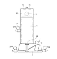
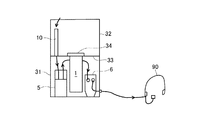
図1は、本発明の第1の実施例である水素水・水素ガス生成装置の構成を示す説明図である。この水素水・水素ガス生成装置は、台板2に特許文献1に記載のような金属などの水素ガス発生部材を液中に投入して水素ガスを発生させる水素ガス発生器1を設け、この水素ガス発生器1で発生した水素ガスを底部の焼結金属フィルタ43を通して内部に取り込み、水に溶け込ませ、かつ上部の空気内に混合させる水素水生成タンク4と、前記水素水生成タンク4の上部で液面上の水素ガスを含む空気をこの容器外に取り出す取り出しポート7a,7bを有する水素水生成タンクの蓋44とから構成される。
FIG. 1 is an explanatory diagram showing the configuration of a hydrogen water / hydrogen gas generator according to a first embodiment of the present invention. This hydrogen water / hydrogen gas generating apparatus is provided with a
水素ガス発生器1で発生した水素ガスは微細な気泡となって焼結金属フィルタ43から水素水生成タンク4内に入り、一部は水に溶けて水素水となり、残りの気泡は液面上の空気に混入する。
The hydrogen gas generated by the
水素水生成タンク4の蓋44には、エアポンプ5と、二箇所の水素ガスの取り出しポート7a,7bとが設けられている。取り出しポート7a,7bはいずれも水素水生成タンク4内の圧力を示す1次圧力計と、圧力を調整するレギュレータと、レギュレータ出側の圧力を示す2次圧力計をこの順に備えており、取り出しポート7aにはドージングツールを接続する。ガスのオン・オフ制御はツール側で行う。
The
取り出しポート7bの経路には2次圧力計の出側に更に流量調整弁と電磁弁、エアポンプ5が接続され、水素ガス吸入用のツールを接続する。
A flow rate adjusting valve, a solenoid valve, and an
水素水を使用する場合は排出弁11から取り出す。実験によると、1次圧(内部圧)と水素濃度とはほぼ比例し、100kPaで1.0ppm、500kPaで5.0ppmの水素水が得られる。
When using hydrogen water, it is taken out from the
水素ガス発生器1に投入する水素ガス発生部材は、4gでおよそ5リットルの水素ガスを発生する。水素水生成タンク4の容量を仮に1リットルとすれば、水素ガスの発生を続けていると水素水生成タンク4の上部の気体部分の圧力がどんどん上昇するから、目的に応じて1次圧力計により圧力を調整する必要がある。水として温水を使用したり、小形ヒータを使用するなどして水温を上昇させると、水素ガスの発生速度を向上させることができる。
The hydrogen gas generating member charged into the
水素ガス吸入の場合は比較的低濃度のガスが好ましいが、低圧・微量のガスでは吸入の体感を得られないので、エアポンプ5により空気を加えて、鼻や口に吹きかけるようにするのである。流量調整弁でガスの放出時間を選択する。また排出弁11に直接スプレイノズルを取り付ければ、水素水ミストが得られる。
In the case of hydrogen gas inhalation, a relatively low concentration gas is preferable. However, since the inhalation experience cannot be obtained with a low pressure and a very small amount of gas, air is added by the
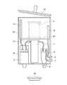
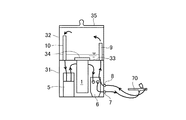
図2は本発明の第2の実施例の水素水・水素ガス生成装置を示す説明図である。中孔を設けた中仕切り33で上下に仕切られた縦型の容器の下部ケーシング31内には、金属などの水素ガス発生部材を液中に投入して水素ガスを発生させる上部が開放されたカップ状の水素ガス発生器1と、この水素ガス発生器1内に空気を送り込むエアポンプ5と、この水素ガス発生器1から吐き出される水素ガスを含む空気を濾過するエアフィルタ6が収納されるとともにこのエアフィルタ6を通過した水素ガスを含む空気をこの容器外に取り出す取り出しポート7とが設けられている。取り出しポート7は、オン・オフを制御するためバルブ付きのものである。また上部ケーシング32には、上部ケーシング32内に開口して前記エアポンプ5に空気を取り込む吸気管10が収められている。
FIG. 2 is an explanatory view showing a hydrogen water / hydrogen gas generator of a second embodiment of the present invention. In the
水素ガス発生器1は中仕切り33の中孔から吊り下げた状態に支持されている。内部には特許文献1に記載のように水を入れ、水素発生部材である金属粉を投入する。水素ガス発生器1の上面は開放されているが、この図では、その上に想像線で示す水素水生成タンク4を置くことにより塞がっている。水素水生成タンク4を載置しないときは図2の下部に示す中蓋34を使用して塞ぐことができる。また縦型の容器の上部、すなわち上部ケーシング32の開口部は、必要に応じて上蓋35により塞ぐことができる。気体を循環させる場合は上蓋35を使用する。
The
さらに、水素ガスを回収・循環させる場合のために、例えば下部ケーシング31に前記取り出しポート7と並べて、接続ツールからの不純物を含む戻りガスを容器内に取り込む戻入ポート8を設け、これに接続して不純物を含む戻りガスを上部ケーシング32内に吐き出す吐出し管9を備えている。
Further, in order to collect and circulate hydrogen gas, for example, a
エアポンプ5は小形のダイアフラムポンプなどがよい。吐出側には逆止弁51を設ける。エアフィルタ6は特に限定しない。気体中の水滴が溜まるので、底部に水抜き61を設ける。水素水を生成させる場合は、図3に示すような水素水生成タンク4を使用する。
The
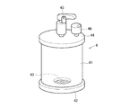
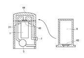
図3は、水素水生成タンク4を示す斜視図である。円筒状の胴部41と底板42でカップ状に構成されたタンク本体の底板には、液体は滲み出す程度で、気体は透過できる焼結金属フィルタ43を嵌装してある。水素水生成タンク4内に水を入れ、焼結金属フィルタ43を透過した水素ガスの気泡が水に溶け込むことによりこの水素水生成タンク4内に水素水が生成される。
FIG. 3 is a perspective view showing the hydrogen
水素水生成タンク4の蓋44には放散弁45と圧力計46が取り付けられている。水素ガスが多量に取り込まれて内部圧力が高まった場合は、圧力計46の指示により放散弁45を使用して適宜放散させる。水素ガスは大気圧では1.8ppm程度しか水に溶けないが、40ないし300kPaの圧力にすると3.0ppm位まで溶けるので、有効な水素水が得られる。水素水生成タンク4内に水に代えて石鹸水を入れれば、水素ガスを含むフォームを形成させることができる。また化粧水を入れれば、化粧成分のある水素水を生成できる。なお、水素水生成タンク4を装置から取り出す場合は、水の滲みだしを防止するため適宜底部に下栓をすることが望ましい。
A
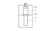
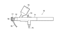
図4は、この水素水生成モードにおける水素水・水素ガス生成装置の使用状態である。中仕切り33に中蓋34は使用せず、代わりに水素水生成タンク4が載置される。上蓋35は使用せず、エアポンプ5、気体配管なども使用しない。水素ガスを吹き付ける場合は、図5に示すようなスプレイツール70を使用する。このスプレイツールは、本出願人が前記特許文献2に記載したものと同じである。
FIG. 4 shows a use state of the hydrogen water / hydrogen gas generator in the hydrogen water generation mode. The
市販の塗装用エアブラシを基本とし、本体71の先端にスプレイノズル72と液体容器74を備えており、操作レバー73により適宜噴射させることができるが、本発明の場合、スプレイノズル72の先端にフード77を取り付け、クッション部材78を取り付けて、皮膚などに軽く押しつけて使用することができる。液体容器74内に水、化粧水、石鹸水などを入れることにより、皮膚への水素の供給だけでなく洗浄なども行うことができる。本体71の下部には気体供給配管75が接続され、フード77内には余剰の気体を吸い出す気体吸い出し配管76が開口しており、余剰の気体を回収して循環使用できる。
The
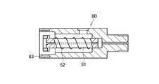
図6は、スプレイツールに代えて使用することのできるタッピングツール80の一例を示す断面図である。フードに相当する部材の内部にスライドピース81、これを押し出すばね82を備え、先端に接触センサ83を設けることにより、所定の接触圧力で連続的に皮膚を軽く叩きながら水素を供給することで、水素の効果にリフティングと呼ばれる一種のマッサージ効果も付加することができる。これも特許文献2に記載したものと同じである。
FIG. 6 is a cross-sectional view showing an example of a
図7は、本実施例のスプレイモードにおける水素水・水素ガス生成装置の使用状態である。中仕切り33の中孔は中蓋34で塞ぎ、上部ケーシング32も上蓋35で塞いである。上部ケーシング32内は気密室となり、吸気管10から内部の気体を吸引してエアポンプ5で水素ガス発生器1に送り、水素ガスが添加された気体がエアフィルタ6を経て取り出しポート7からスプレイツール70に送られ、回収気体は戻入ポート8から吐出し管9を経て上部ケーシング32内に戻って循環する。上部ケーシング32の内部は水素ガスを含む空気で満たされているが、水素は軽いので上部に多く溜まるから、吸気管の開口位置はできるだけ高いほうが望ましい。スプレイツール70からは汚れを含む水分も戻って来るが、これらは吐出し管9の開口部を少なくとも吸気管10の開口よりも低くし、水滴がケーシングの壁に当たるようにすれば、壁から流れ落ち、上部ケーシング32内に溜まるので、吸気管10から再び吸い込まれることはない。汚れた水は大量に溜まらないうちに適宜処分すればよい。
FIG. 7 shows the state of use of the hydrogen water / hydrogen gas generator in the spray mode of this embodiment. The inner hole of the
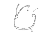
本実施例の水素水・水素ガス生成装置で水素ガスを吸入する場合は、水素ガスを循環させず、単に鼻や口から吸入する。図8はこのモードで使用する吸入ツール90の一例を示す斜視図で、電話や録音等で使用する小形マイクロホンと同じように首、衣服の襟等に引っかけて使用する。弓状の支持部91の一端から水素チューブが伸び、先端に吹き出し口92が設けてあるので、これが口の前になるようにして使用する。この他にも使い捨て形のマスクなどに水素チューブを接続してもよい。
When the hydrogen water is inhaled by the hydrogen water / hydrogen gas generating apparatus of the present embodiment, the hydrogen gas is not circulated but simply inhaled from the nose or mouth. FIG. 8 is a perspective view showing an example of the
図9は、本実施例の吸入モードにおける水素水・水素ガス生成装置の使用状態である。このモードでは水素ガスの回収は行わないので循環ループを構成する必要がないから上部ケーシングは開放状態でよく、上蓋35、戻入ポート8は使用しない。
FIG. 9 shows the usage state of the hydrogen water / hydrogen gas generator in the suction mode of this embodiment. In this mode, no recovery of hydrogen gas is performed, so there is no need to form a circulation loop, so the upper casing may be open, and the
使用目的を水素水の利用や水素ガスの吸入などに限定し、水素−空気の混合ガスを循環使用することを行わないとすれば、実施例2における上部ケーシング32や戻入ポート8、吐出し管9などはすべて不要となり、装置をいっそう簡略化することができる。
If the purpose of use is limited to the use of hydrogen water or the suction of hydrogen gas, and the mixture of hydrogen and air is not circulated, the
図10は第3の実施例の水素水・水素ガス生成装置の一例を示す説明図であり、図10において各符号は図1、図2と同じである。図2の下部ケーシング31に相当するスタンドに水素ガス発生器1が支持されており、蓋44が被せられている。蓋44の内部で、水素ガス発生器1内で発生した水素ガスが焼結金属フィルタ43により水滴が除去され、エアポンプ5から送られる空気と合流して取り出しポート7に向かっている。吸入などの水素ガスはここから利用する。一方、蓋44を右に示した水素水生成タンク4に置き換えて水素ガス発生器1の上部に載置すれば水素ガス発生器1内に水素水が生成されるから、水素水、石鹸入り水素水その他が利用できる。なお、この図10で蓋44内の焼結金属フィルタ43は単に水滴を除去するだけで大きな圧力はかからないので、簡単な樹脂フィルタでもよい。
FIG. 10 is an explanatory view showing an example of the hydrogen water / hydrogen gas generator of the third embodiment. In FIG. 10, the reference numerals are the same as those in FIGS. The
本発明の水素水・水素ガス生成装置は水素ガスを含む液体やガスを簡単に生成できるので、この他にもさまざまな使用法が考えられる。 Since the hydrogen water / hydrogen gas generating apparatus of the present invention can easily generate a liquid or gas containing hydrogen gas, various other uses are conceivable.
1…水素ガス発生器、 2…台板、 31…下部ケーシング、 32…上部ケーシング、 33…中仕切り、 34…中蓋、 35…上蓋、 4…水素水生成タンク、 43…焼結金属フィルタ、 44…蓋、 5…エアポンプ、 6…エアフィルタ、 7a,7b,7…取り出しポート、 8…戻入ポート、 9…吐出し管、 10…吸気管、 11…排出弁、 70…スプレイツール、 80…タッピングツール、 90…吸入ツール。
DESCRIPTION OF
Claims (6)
この水素ガス発生器で発生した水素ガスを底部フィルタを通して内部に取り込んで水に溶け込ませかつ上部の空気内に混合させる水素水生成タンクと、
前記水素水生成タンク上部の水素ガスを含む空気をこの水素水生成タンク外に取り出す取り出しポートを有する水素水生成タンクの蓋と
からなる水素水・水素ガス生成装置。 A hydrogen gas generator that generates hydrogen gas by introducing a hydrogen gas generating member into the liquid;
A hydrogen water generation tank in which hydrogen gas generated by the hydrogen gas generator is taken into the inside through a bottom filter, dissolved in water, and mixed in the upper air;
A hydrogen water / hydrogen gas generating device comprising a lid of a hydrogen water generating tank having a take-out port for taking out air containing hydrogen gas above the hydrogen water generating tank from the hydrogen water generating tank.
この水素ガス発生器内に空気を送り込むエアポンプと、
この水素ガス発生器から吐き出される水素ガスを含む空気を濾過するエアフィルタと、
このエアフィルタを通過した水素ガスを含む空気をこの容器外に取り出す取り出しポートと、
前記容器における前記中仕切りで仕切られた上部ケーシング内に開口して前記エアポンプに空気を取り込む吸気管と、
前記縦型の容器の上部を塞ぐ着脱自在の上蓋と、
前記の水素ガス発生器で発生した水素ガスを底部フィルタを通して内部に取り込み、水に溶け込ませ、かつ上部の空気内に混合させる水素水生成タンクと
からなり、
前記水素ガス発生器が前記中仕切りの下部に支持され、前記中蓋によって中仕切りの中孔と同時に前記水素ガス発生器上部も塞がれるようになっている
ことを特徴とする水素水・水素ガス生成装置。 It is housed in the lower casing of a vertical container that is vertically divided by a partition having an inner hole closed by a removable inner lid, and a hydrogen gas generating member is put into the liquid to supply hydrogen gas. A hydrogen gas generator with an open top, and
An air pump that feeds air into the hydrogen gas generator;
An air filter for filtering air containing hydrogen gas discharged from the hydrogen gas generator;
A take-out port for taking out air containing hydrogen gas that has passed through the air filter, and
An intake pipe that opens into the upper casing partitioned by the partition in the container and takes air into the air pump;
A detachable upper lid that closes the upper part of the vertical container;
The hydrogen gas generated in the hydrogen gas generator is taken into the inside through a bottom filter, and is composed of a hydrogen water generation tank that is dissolved in water and mixed in the upper air.
The hydrogen gas generator is supported by the lower part of the partition, and the upper part of the hydrogen gas generator is closed simultaneously with the inner hole of the partition by the inner lid. Gas generator.
この水素ガス発生器内に空気を送り込むエアポンプと、
この水素ガス発生器から吐き出される水素ガスを含む空気を濾過するエアフィルタと、 このエアフィルタを通過した水素ガスを含む空気をこの容器外に取り出す取り出しポートを有するとともに前記水素ガス発生器の容器の上部を塞ぐ着脱自在の蓋と、
前記の水素ガス発生器で発生した水素ガスを底部フィルタを通して内部に取り込んで水に溶け込ませかつ上部の空気内に混合させる水素水生成タンクと
からなり、
前記水素ガス発生器が前記の蓋または前記の水素水生成タンクのいずれかによって上部が塞がれるようになっていることを特徴とする水素水・水素ガス生成装置。
A hydrogen gas generator having an open upper portion for generating hydrogen gas by introducing a hydrogen gas generating member into the liquid;
An air pump that feeds air into the hydrogen gas generator;
An air filter for filtering air containing hydrogen gas discharged from the hydrogen gas generator; a take-out port for taking out air containing hydrogen gas that has passed through the air filter; and a container for the hydrogen gas generator. A removable lid that closes the top,
A hydrogen water generation tank that takes in the hydrogen gas generated by the hydrogen gas generator through the bottom filter, dissolves it in water, and mixes it in the upper air;
The hydrogen gas generator hydrogen water-hydrogen gas generation apparatus characterized that it is earthenware pots by the top is closed by either the lid or the hydrogen water generating tank.
Priority Applications (1)
| Application Number | Priority Date | Filing Date | Title |
|---|---|---|---|
| JP2015099597A JP6571385B2 (en) | 2015-05-15 | 2015-05-15 | Hydrogen water / hydrogen gas generator |
Applications Claiming Priority (1)
| Application Number | Priority Date | Filing Date | Title |
|---|---|---|---|
| JP2015099597A JP6571385B2 (en) | 2015-05-15 | 2015-05-15 | Hydrogen water / hydrogen gas generator |
Publications (2)
| Publication Number | Publication Date |
|---|---|
| JP2016216273A JP2016216273A (en) | 2016-12-22 |
| JP6571385B2 true JP6571385B2 (en) | 2019-09-04 |
Family
ID=57580243
Family Applications (1)
| Application Number | Title | Priority Date | Filing Date |
|---|---|---|---|
| JP2015099597A Active JP6571385B2 (en) | 2015-05-15 | 2015-05-15 | Hydrogen water / hydrogen gas generator |
Country Status (1)
| Country | Link |
|---|---|
| JP (1) | JP6571385B2 (en) |
Families Citing this family (1)
| Publication number | Priority date | Publication date | Assignee | Title |
|---|---|---|---|---|
| JP7824677B2 (en) * | 2023-08-28 | 2026-03-05 | 株式会社アドバンス | Hydrogen suction device |
Family Cites Families (3)
| Publication number | Priority date | Publication date | Assignee | Title |
|---|---|---|---|---|
| JP2013146373A (en) * | 2012-01-19 | 2013-08-01 | Tatsunori Yamaji | Hydrogen generator |
| CN104583137B (en) * | 2013-08-26 | 2016-04-13 | 皆川浩章 | Portable rich hydrogen water generation kettle |
| JP5613853B1 (en) * | 2014-04-11 | 2014-10-29 | 五十嵐 秀夫 | Portable hydrogen water generating apparatus and hydrogen gas generating member used in the apparatus |
-
2015
- 2015-05-15 JP JP2015099597A patent/JP6571385B2/en active Active
Also Published As
| Publication number | Publication date |
|---|---|
| JP2016216273A (en) | 2016-12-22 |
Similar Documents
| Publication | Publication Date | Title |
|---|---|---|
| KR101630356B1 (en) | Portable Automatic Mist Apparatus | |
| JP2002066198A (en) | Fluid supply source and reservoir for clothing refreshing equipment | |
| CN203100055U (en) | Humidifier with bottom of water tank and top of water | |
| JP2013221733A (en) | Hydrogen and oxygen-included ultrafine water droplet generating device, and attachment for generating hydrogen | |
| JP3203575U7 (en) | ||
| JP6571385B2 (en) | Hydrogen water / hydrogen gas generator | |
| JP2012019825A (en) | Face washing device | |
| CN206295047U (en) | A kind of double spray structure nano spraying moisturizing instrument | |
| JP2011234784A (en) | Sprayer for hot air bathing | |
| KR20150076990A (en) | Humidifacation type air cleaner | |
| CN217464736U (en) | Independent atomizing champignon humidifier of profit | |
| KR20090124200A (en) | Incense Injector | |
| JP2000288054A (en) | Bubble generator | |
| JPH0311004Y2 (en) | ||
| CN202355614U (en) | A car air vent aromatherapy device | |
| CN209866366U (en) | Shower device | |
| KR20180076844A (en) | Essential oil sprayer | |
| JP3211227U (en) | Liquid supply tank and steam spraying device | |
| JP2016150225A (en) | Facial care equipment | |
| JPH04348758A (en) | Inhaler | |
| CN113197365A (en) | Anti-clogging atomizer | |
| CN222150592U (en) | Aromatherapy release device that can be used in shower room | |
| CN223568855U (en) | Running water box | |
| JP2013212298A (en) | Facial treatment device | |
| JPH061154Y2 (en) | Inhaler |
Legal Events
| Date | Code | Title | Description |
|---|---|---|---|
| A621 | Written request for application examination |
Free format text: JAPANESE INTERMEDIATE CODE: A621 Effective date: 20180514 |
|
| A977 | Report on retrieval |
Free format text: JAPANESE INTERMEDIATE CODE: A971007 Effective date: 20190227 |
|
| A131 | Notification of reasons for refusal |
Free format text: JAPANESE INTERMEDIATE CODE: A131 Effective date: 20190312 |
|
| A521 | Request for written amendment filed |
Free format text: JAPANESE INTERMEDIATE CODE: A523 Effective date: 20190507 |
|
| TRDD | Decision of grant or rejection written | ||
| A01 | Written decision to grant a patent or to grant a registration (utility model) |
Free format text: JAPANESE INTERMEDIATE CODE: A01 Effective date: 20190709 |
|
| A61 | First payment of annual fees (during grant procedure) |
Free format text: JAPANESE INTERMEDIATE CODE: A61 Effective date: 20190808 |
|
| R150 | Certificate of patent or registration of utility model |
Ref document number: 6571385 Country of ref document: JP Free format text: JAPANESE INTERMEDIATE CODE: R150 |
|
| R250 | Receipt of annual fees |
Free format text: JAPANESE INTERMEDIATE CODE: R250 |