JP4483722B2 - Inhaler - Google Patents
Inhaler Download PDFInfo
- Publication number
- JP4483722B2 JP4483722B2 JP2005187170A JP2005187170A JP4483722B2 JP 4483722 B2 JP4483722 B2 JP 4483722B2 JP 2005187170 A JP2005187170 A JP 2005187170A JP 2005187170 A JP2005187170 A JP 2005187170A JP 4483722 B2 JP4483722 B2 JP 4483722B2
- Authority
- JP
- Japan
- Prior art keywords
- inhaler
- storage case
- liquid
- main body
- attachment
- Prior art date
- Legal status (The legal status is an assumption and is not a legal conclusion. Google has not performed a legal analysis and makes no representation as to the accuracy of the status listed.)
- Expired - Fee Related
Links
Images
Landscapes
- Containers And Packaging Bodies Having A Special Means To Remove Contents (AREA)
Description
本発明は、人体の呼吸器系の炎症治療などの目的で液体噴霧の吸入に用いる吸入器に関する。The present invention relates to an inhaler used for inhalation of a liquid spray for the purpose of treating inflammation of the respiratory system of a human body.
従来から、人体の呼吸器系の炎症治療などのために薬液や水の噴霧を発生させてその噴霧を吸入することが行われている。吸入器は、噴霧を発生して吸入させる装置である。一般的な装置構成は、ノズルから吹き出す噴出蒸気が発生する負圧で薬液や水を吸い上げると共に噴霧状にし、その噴霧を喉や鼻に導くという構成になっている(例えば、特許文献1,2参照)。
しかしながら、上述した特許文献1,2に示されるような吸入器は、通常、卓上に吸入器を置き、使用者が椅子に腰掛けてこれを使用することが想定されているものの、これを使用する際の使用者の座高の違いなどに対する配慮がなされておらず、無理な姿勢での吸入を強いられることがある。吸入器の使用者は、小さな子供から大きな大人まで座高が大きく異なり、また、吸入は、一定の姿勢で比較的長時間行うことが多いので、何れの使用者にとっても楽な姿勢で吸入できる吸入器が望まれる。
However, inhalers such as those shown in
本発明は、上記課題を解消するものであって、簡単な構成により、吸入時の無理な姿勢を楽な姿勢に改善できる吸入器を提供することを目的とする。 An object of the present invention is to solve the above-mentioned problems, and to provide an inhaler capable of improving an unreasonable posture during inhalation to an easy posture with a simple configuration.
上記課題を達成するために、請求項1の発明は、水蒸気を生成してその水蒸気により液体を噴霧する吸入器において、水を注ぎ込んで貯留する給水タンクと、前記給水タンクから引き込んだ水を沸騰させるヒータと、前記ヒータにより沸騰して得られる水蒸気を噴出すると共に負圧を発生する噴出ノズルと、液体を貯留する液体カップと、前記噴出ノズル付近に配置され前記液体カップの液体を前記噴出ノズルの発生する負圧で吸い上げると共にその液体を霧状に噴霧する液体ノズルと、前記噴出ノズルからの水蒸気及び前記液体ノズルからの噴霧液を口及び又は鼻へ導くアタッチメントとを有する吸入器本体、及び前記吸入器本体を収納する収納ケースを備え、前記収納ケースは、収納ケース本体と該収納ケース本体の左右の側面において該収納ケース本体に嵌合する高さ調節脚部とから構成され、収納した吸入器本体を取り出した後、その吸入器本体を上に載せる台となり、前記吸入器本体を載せる台として用いる際に、前記収納ケース本体と前記高さ調節脚部との嵌合位置を変えることにより前記吸入器本体の高さを変更できるものである。
In order to achieve the above object, the invention of
請求項2の発明は、請求項1に記載の吸入器において、前記収納ケースは、前記吸入器本体を収納した際に前記吸入器本体上部を覆うものである。 According to a second aspect of the present invention, in the inhaler according to the first aspect, the housing case covers the upper portion of the inhaler body when the inhaler body is housed.
請求項3の発明は、請求項1又は請求項2に記載の吸入器において、前記アタッチメントは、当該吸入器本体の使用状態と収納状態とで取付方向を変更できるものである。 According to a third aspect of the present invention, in the inhaler according to the first or second aspect, the attachment can change an attachment direction depending on a use state and a storage state of the inhaler body.
請求項4の発明は、請求項1に記載の吸入器において、前記収納ケースは、内部に液体を注入可能であると共に注入した液量計測が可能となる目盛を備えているものである。 According to a fourth aspect of the present invention, in the inhaler according to the first aspect, the storage case is provided with a scale capable of injecting a liquid therein and measuring the amount of the injected liquid.
請求項1の発明によれば、収納ケースを台として用いる場合と用いない場合の二段階の高さ調整ができるので、大人と子供のように大きな座高差のある何れの使用者に対しても吸入時に無理な姿勢を強いることなく楽な姿勢で吸入できるように改善できる。収納ケースそのものが台となるので、台を別途設ける必要がなく、また、紛失するおそれがない。また、収納ケースが高さ調整機能を有する台として使えるので、至便性が増し、吸入時の無理な姿勢を楽な姿勢に改善できる。 According to the first aspect of the present invention, since the height of the storage case can be adjusted in two steps when the storage case is used as a stand and when it is not used, it can be used for any user having a large difference in sitting height such as an adult and a child. It can be improved so that it can be inhaled in a comfortable posture without forcing an unreasonable posture during inhalation. Since the storage case itself becomes a table, there is no need to provide a table separately and there is no risk of losing it. Moreover, since the storage case can be used as a stand having a height adjustment function, convenience is increased, and an unreasonable posture during inhalation can be improved to a comfortable posture.
請求項2の発明によれば、上方から吸入器本体内部への、ごみ等の異物進入を防止でき、吸入器を清潔な状態に保つことができる。
According to the invention of
請求項3の発明によれば、通常、使用状態において出っ張って取り付けられるアタッチメントを、収納時にコンパクトに配置して吸入器本体を収納できる。 According to the third aspect of the present invention, the inhaler main body can be accommodated by arranging the attachment that protrudes and attaches normally in the use state in a compact manner when accommodated.
請求項4の発明によれば、収納ケースそのものが計量器であるので、別途に計量器を設ける必要がなく、また、計量器が紛失するおそれがない。 According to the invention of claim 4 , since the storage case itself is a measuring instrument, there is no need to separately provide a measuring instrument, and there is no possibility that the measuring instrument is lost.
以下、本発明の実施形態に係る吸入器について、図面を参照して説明する。 Hereinafter, an inhaler according to an embodiment of the present invention will be described with reference to the drawings.
(第1の実施形態)
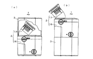
図1(a)は本発明の第1の実施形態に係る吸入器1の収納状態を示し、図1(b)は吸入器1の使用時の状態を示し、図2は吸入器1の吸入器本体2を示し、図3(a)(b)は吸入器の使用例を示す。吸入器1は、図1(a)に示すように、吸入器本体2と、吸入器本体2を収納する上方が開口した収納ケース3とを備えており、非使用時には収納ケース3に吸入器本体2が収納される。収納ケース3は、図1(b)に示すように、収納した吸入器本体を取り出した後、収納状態から倒立させた状態で、吸入器本体2を上に載せる台として用いることができる。
(First embodiment)
FIG. 1A shows a stored state of the
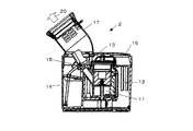
吸入器本体2は、図2に示すように、水を注ぎ込んで貯留する給水タンク11と、給水タンク11から引き込んだ水を沸騰させるヒータ12と、ヒータ12により沸騰して得られる水蒸気を噴出すると共に負圧を発生する噴出ノズル13と、液体を貯留する液体カップ14と、噴出ノズル13付近に配置され液体カップの液体を噴出ノズル13の発生する負圧で吸い上げると共にその液体を霧状に噴霧する液体ノズル15と、噴出ノズル13からの水蒸気及び液体ノズル15からの噴霧液を口及び又は鼻へ導くアタッチメント17とを備えている。As shown in FIG. 2, the
吸入器本体2はその機能面の観点から、水蒸気を生成してその水蒸気により液体を噴霧状態にする噴霧発生部16と、アタッチメント17との2つに大きく分けることができる。アタッチメント17は斜め上方に開口を有し、この開口から矢印20で示す方向に噴霧が供給される。液体は、吸入器1の使用目的に応じて、薬品の水溶液の他に、水単体も用いられる。なお、後述する他の実施形態における吸入器本体2の構造は、ここに示した吸入器本体2の構造と大略同じであり、以下においては、特に異なる点がある場合のみ説明する。The inhaler
上述の吸入器1は、図3(a)に示すように、吸入器本体2を収納ケース3から成る台に載せた状態で、又は、図3(b)に示すように、吸入器本体2のみの状態で、机上に載置され、椅子に座った使用者Mは、アタッチメント17の開口部に口や鼻をあてがって噴霧液を吸入する。このように、吸入器1は、収納ケース3を台として用いる場合と用いない場合の二段階の高さ調整ができるので、大人と子供のように大きな座高差のある何れの使用者Mも、吸入時に前かがみになったり、背伸びしたりするような無理な姿勢を強いられることがなく、楽な姿勢で吸入できる。収納ケース3そのものが台となるので、台を別途設ける必要がなく、また、紛失するおそれがない。
As shown in FIG. 3 (a), the
(第2の実施形態)
図4(a)(b)は第2の実施形態に係る吸入器1の吸入器本体2を示し、図5(a)は吸入器1の収納状態を示し、図5(b)は吸入器1の使用時状態を示す。この実施形態の吸入器本体2は、図4(a)(b)に示すように、アタッチメント17を噴霧発生部16に対して、そのまま、又は一旦取り外して矢印Rで示すように回転することができる。図4(a)に示すように、アタッチメント17が噴霧発生部16から外方に突出して固定された状態が吸入器本体2の使用状態である。また、図4(b)に示すように、アタッチメント17が噴霧発生部16の内方に向いて固定された状態が吸入器本体2の収納用状態である。
(Second Embodiment)
4A and 4B show the
吸入器1は、図5(a)に示すように、噴霧発生部16と大略同サイズの収納ケース3を備えており、収納ケース3は、吸入器本体2の収納状態において、そのアタッチメント17の部分の全体を覆うように上から被せて用いられる。また、この収納ケース3は、吸入器本体2の使用状態において、吸入器本体2の高さを高くする必要がある場合に、図5(b)に示すように、嵩上げ用の台として用いることができる。収納ケース3を台として用いるときの姿勢は、吸入器本体2を収納していた状態から上下を倒立させた姿勢でもよく、また、収納した状態のままの姿勢としてもよい。
As shown in FIG. 5A, the
このような構造の吸入器本体2と収納ケース3とを備えた吸入器1は、その収納時には、噴霧発生部16と同等サイズでコンパクトに収納できる。従って、省スペースでの保管ができる。また、吸入器1の収納状態において、吸入器本体2と収納ケース3との間に開口が開いておらず、収納ケース3は、アタッチメント17を内部に密閉することができる。従って、吸入器1の収納時は、上方から吸入器本体2の内部への、ごみや埃等の異物進入を防止でき、アタッチメント17の汚れを防止して、吸入器1を清潔な状態に保つことができる。
The
(第3の実施形態)
図6(a)は本発明の第3の実施形態に係る吸入器1の収納状態を示し、図6(b)は吸入器1の使用時の状態を示す。この実施形態の吸入器1は、図6(a)に示すように、吸入器本体2のアタッチメント17を使用状態の位置のままで上方から覆うことができる収納ケース3を備えている。この吸入器1は、上述の第2の実施形態の吸入器1とは異なってアタッチメント17を回転する機構が不要で構造が簡単化されると共に、収納時において、上方からの異物進入を防止する機能を有している。また、収納ケース3が、上述の第2の実施形態の吸入器1のものより大きくてコンパクト性は若干損なわれているが、図6(b)に示すように台として用いる場合、より安定に吸入器本体2を固定できる。
(Third embodiment)
FIG. 6A shows the housed state of the
(第4の実施形態)
図7は本発明の第4の実施形態に係る吸入器1の収納状態を示し、図8(a)(b)は吸入器1の使用状態の例を示す。この吸入器1は、図7に示すように、上述の図1(a)(b)に示した第1の実施形態の吸入器1に対して、収納ケース用の蓋をさらに設けた構造となっている。すなわち、この吸入器1の収納ケース3は、収納ケース本体31とケース蓋32とからなっている。吸入器本体2は、この収納ケース3によって、全体が密閉された状態で、収納される。
(Fourth embodiment)
FIG. 7 shows the storage state of the
また、吸入器1の使用時には、図8(a)に示すように、収納ケース本体31のみを嵩上げ台として用いたり、使用者の座高によってはこれでも不十分な場合には、図8(b)に示すように、ケース蓋32を嵩上げ台として収納ケース本体31と吸入器本体2の間に追加固定して用いたりできる。また、図示していないが、ケース蓋32のみを単独で低い嵩上げ台として用いることもできる。これによって、使用者の座高に合わせて吸入器本体2の高さ調節か可能になり、使用者は、座高によらず無理な姿勢にならずに吸入器を使用できる。
Further, when the
(第5の実施形態)
図9(a)は本発明の第5の実施形態に係る吸入器1の収納状態を示し、図9(b)は吸入器1の吸入器本体2と収納ケース3を分離した状態を示し、図10(a)(b)、図11(a)(b)は収納ケース3の各部品を示し、図12(a)〜(c)は収納ケース3を台として用いた例を示す。この実施形態の吸入器1の収納ケース3は、図9(a)(b)に示すように、上述の図5(a)に示した第2の実施形態の吸入器1と同様に、吸入器本体2の収納時にアタッチメント17を回転してコンパクト、かつ略密閉状態でアタッチメント17を覆うことができる。この収納ケース3は、吸入器本体2を収納していた状態から上下を反転した姿勢で、例えば、4段階の高さ調整機能を有する台として用いられる。収納ケース3は、この高さ調整機能を実現するため、収納ケース本体33と高さ調節脚部34とから構成されている。
(Fifth embodiment)
FIG. 9A shows a storage state of the
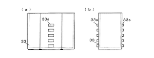
高さ調節脚部34は、図10(a)(b)に示すように、ベース部34aと、ベース部34aの両側に設けられた立上部34bと、からなる。各立上部34bは、上下方向に等間隔で並んだ5つの係止用開口34cを有している。収納ケース本体33は、上述の図5(a)に示した収納ケース3の左右の側面に、前述の係止用開口34cと同様の配列間隔で上下方向に並んだ5つの係止用突起33aを備えた構造となっている。
As shown in FIGS. 10A and 10B, the height adjusting
これらの収納ケース本体33と高さ調節脚部34は、図12(a)(b)に示すように、収納ケース本体33の係止用突起33aを、高さ調節脚部34の係止用開口34cに嵌合した状態で組み合わされて吸入器本体2を嵩上げする台とされる。使用者の座高に合わせて、係止用突起33aと、これを差し込む係止用開口34cとの高さを変えることにより、吸入器本体2の高さ、従ってアタッチメント17の高さを調節することかできる。
As shown in FIGS. 12A and 12B, the storage case
例えば、図12(c)に示すように、下から4つ目と5つ目の係止用開口34cに、収納ケース本体33の下から1つ目と2つ目の係止用突起33aを嵌合させると、係止用突起33aの間隔の3つ分の高さだけ、吸入器本体2を高くできる。収納ケース3が、高さ調整機能を有する台として使えるので、吸入器1の至便性が増し、使用者は、吸入時に無理な姿勢をとることなく楽な姿勢で吸入器1を利用できる。
For example, as shown in FIG. 12C, the first and
(第6の実施形態)
図13(a)(b)(c)は本発明の第6の実施形態に係る吸入器1の収納状態を示し、図14は吸入器1の収納ケース3を示し、図15は吸入器1の使用状態を示す。この実施形態の吸入器1の収納ケース3は、図13(a)〜(c)に示すように、上述の図5(a)に示した第2の実施形態の吸入器1と同様に、吸入器本体2の収納時にアタッチメント17を回転してコンパクト、かつ略密閉状態でアタッチメント17を覆うことができる。この収納ケース3は、さらに、内部空間にリブを追加して形成した小さなカップ部36を備えている。
(Sixth embodiment)
FIGS. 13A, 13B and 13C show the storage state of the
収納ケース3は、図14に示すように、透明材を用いて中が透けて見えるよう形成されている。また、カップ部36の外側には、カップ部36内の内容積に対応する目盛37が設けられている。このカップ部36は、給水タンク11(図2)内に水を注ぎ込んで貯留する際に、水量計として、また給水カップとして用いることができる。収納ケース3が計量カップを兼用できるので、計量カップを別途設けることが不要となる。
As shown in FIG. 14, the
通常、水蒸気による負圧を利用する、いわゆるスチームタイプの吸入器は、使用時間に対応して決まった量の水を給水タンク11入れて使用する。従って、計量カップが付属品として必須であり、従来は、計量できる吸水カップを別途に用意していた。本発明の吸入器1では、収納ケース3が計量カップ及び給水カップを兼用して液量計測が可能であり、計量カップの準備や収納の煩わしさが軽減でき、計量カップの紛失の心配もない。また、収納ケース3は、図15に示すように、吸入器本体を嵩上げする台としても用いることができる。
Usually, a so-called steam-type inhaler that uses the negative pressure due to water vapor is used in a
なお、本発明は、上記構成に限られることなく種々の変形が可能である。例えば、吸入器本体2及び収納ケース3の形状や構造等は、上記以外でもよい。また、実施形態5の吸入器における係止用突起33aと係止用開口34cの個数数と配列間隔は、上述したものに限られず、個数を増やしたり減らしたり、また、間隔を狭めたり広げたりしたものでもよい。
The present invention is not limited to the above-described configuration, and various modifications can be made. For example, the shapes and structures of the
1 吸入器
2 吸入器本体
3 収納ケース
11 給水タンク
12 ヒータ
13 噴出ノズル
14 液体カップ
15 液体ノズル
17 アタッチメント
37 目盛
DESCRIPTION OF
Claims (4)
水を注ぎ込んで貯留する給水タンクと、前記給水タンクから引き込んだ水を沸騰させるヒータと、前記ヒータにより沸騰して得られる水蒸気を噴出すると共に負圧を発生する噴出ノズルと、液体を貯留する液体カップと、前記噴出ノズル付近に配置され前記液体カップの液体を前記噴出ノズルの発生する負圧で吸い上げると共にその液体を霧状に噴霧する液体ノズルと、前記噴出ノズルからの水蒸気及び前記液体ノズルからの噴霧液を口及び又は鼻へ導くアタッチメントとを有する吸入器本体、及び前記吸入器本体を収納する収納ケースを備え、
前記収納ケースは、収納ケース本体と該収納ケース本体の左右の側面において該収納ケース本体に嵌合する高さ調節脚部とから構成され、収納した吸入器本体を取り出した後、その吸入器本体を上に載せる台となり、前記吸入器本体を載せる台として用いる際に、前記収納ケース本体と前記高さ調節脚部との嵌合位置を変えることにより前記吸入器本体の高さを変更できることを特徴とする吸入器。 In an inhaler that generates water vapor and sprays liquid with the water vapor,
A water supply tank for pouring and storing water, a heater for boiling water drawn from the water supply tank, a water jet obtained by boiling by the heater and a discharge nozzle for generating negative pressure, and a liquid for storing liquid A cup, a liquid nozzle arranged near the ejection nozzle and sucking up the liquid in the liquid cup with a negative pressure generated by the ejection nozzle and spraying the liquid in a mist form, water vapor from the ejection nozzle and the liquid nozzle An inhaler body having an attachment for guiding the spray liquid to the mouth and / or nose, and a storage case for housing the inhaler body,
The storage case is composed of a storage case main body and height adjusting legs that fit into the storage case main body on the left and right side surfaces of the storage case main body. After the stored inhaler main body is taken out, the inhaler main body Ri Do a trapezoidal be placed on top, when used as a base for mounting the inhaler body, change the height of the inhaler body by changing the fitting positions of the storage case body and the height adjustable legs inhalers, characterized in Rukoto can.
Priority Applications (1)
| Application Number | Priority Date | Filing Date | Title |
|---|---|---|---|
| JP2005187170A JP4483722B2 (en) | 2005-06-27 | 2005-06-27 | Inhaler |
Applications Claiming Priority (1)
| Application Number | Priority Date | Filing Date | Title |
|---|---|---|---|
| JP2005187170A JP4483722B2 (en) | 2005-06-27 | 2005-06-27 | Inhaler |
Publications (3)
| Publication Number | Publication Date |
|---|---|
| JP2007000541A JP2007000541A (en) | 2007-01-11 |
| JP2007000541A5 JP2007000541A5 (en) | 2007-02-22 |
| JP4483722B2 true JP4483722B2 (en) | 2010-06-16 |
Family
ID=37686671
Family Applications (1)
| Application Number | Title | Priority Date | Filing Date |
|---|---|---|---|
| JP2005187170A Expired - Fee Related JP4483722B2 (en) | 2005-06-27 | 2005-06-27 | Inhaler |
Country Status (1)
| Country | Link |
|---|---|
| JP (1) | JP4483722B2 (en) |
Families Citing this family (2)
| Publication number | Priority date | Publication date | Assignee | Title |
|---|---|---|---|---|
| JP5296030B2 (en) * | 2010-09-24 | 2013-09-25 | パナソニック株式会社 | Electric inhaler |
| CN114225166B (en) * | 2022-01-24 | 2024-01-09 | 深圳市万雾互联科技有限公司 | Adjustable medical atomizer and working method thereof |
-
2005
- 2005-06-27 JP JP2005187170A patent/JP4483722B2/en not_active Expired - Fee Related
Also Published As
| Publication number | Publication date |
|---|---|
| JP2007000541A (en) | 2007-01-11 |
Similar Documents
| Publication | Publication Date | Title |
|---|---|---|
| CA2309732C (en) | Inhalation device | |
| US6732731B1 (en) | Medical mechanical compressor nebulizer | |
| JP5267245B2 (en) | Nebulizer and functional unit detachable from nebulizer | |
| JP2003102837A (en) | Suction auxiliary implement for atomizer and atomizer having the same | |
| US12127586B2 (en) | Electronic cigarette atomizing core and atomizer | |
| WO2010098430A1 (en) | Gas mist inhaler | |
| JP2006212203A (en) | Inhaler and liquid medical agent discharge cartridge | |
| JP4483722B2 (en) | Inhaler | |
| EP2143457A1 (en) | Inhaler | |
| CN102427794A (en) | Spraying cleaner for health care | |
| US20050150491A1 (en) | Steam inhaler | |
| US20140251321A1 (en) | Inhaler mouthpiece | |
| JP3209915U (en) | Nebulizer | |
| JP3654231B2 (en) | Nebulizer inhalation attachment | |
| US20060137683A1 (en) | Nozzle | |
| CN110812632B (en) | Oxygen-driven jet type atomizer for nursing respiratory diseases of children | |
| JP5628699B2 (en) | Oxygen supply equipment | |
| KR20230048987A (en) | Nebulizer | |
| JP3184470U (en) | Hydrogen gas suction device | |
| EP3459577B1 (en) | Nebulizer for aerosolizing a drug solution with an inner flared-out structure limiting the aerosol waste | |
| JP2009050646A (en) | Ultrasonic mist bath apparatus | |
| JP7349368B2 (en) | Multifunctional hydrogen generator | |
| JPS635728Y2 (en) | ||
| CN215585112U (en) | Timing mist storage tank | |
| JP4507675B2 (en) | Hot bubble bath booth equipment |
Legal Events
| Date | Code | Title | Description |
|---|---|---|---|
| A521 | Written amendment |
Free format text: JAPANESE INTERMEDIATE CODE: A523 Effective date: 20061117 |
|
| A621 | Written request for application examination |
Free format text: JAPANESE INTERMEDIATE CODE: A621 Effective date: 20070810 |
|
| A977 | Report on retrieval |
Free format text: JAPANESE INTERMEDIATE CODE: A971007 Effective date: 20091126 |
|
| A131 | Notification of reasons for refusal |
Free format text: JAPANESE INTERMEDIATE CODE: A131 Effective date: 20091201 |
|
| A521 | Written amendment |
Free format text: JAPANESE INTERMEDIATE CODE: A523 Effective date: 20100201 |
|
| TRDD | Decision of grant or rejection written | ||
| A01 | Written decision to grant a patent or to grant a registration (utility model) |
Free format text: JAPANESE INTERMEDIATE CODE: A01 Effective date: 20100302 |
|
| A01 | Written decision to grant a patent or to grant a registration (utility model) |
Free format text: JAPANESE INTERMEDIATE CODE: A01 |
|
| A61 | First payment of annual fees (during grant procedure) |
Free format text: JAPANESE INTERMEDIATE CODE: A61 Effective date: 20100315 |
|
| R150 | Certificate of patent or registration of utility model |
Free format text: JAPANESE INTERMEDIATE CODE: R150 |
|
| FPAY | Renewal fee payment (event date is renewal date of database) |
Free format text: PAYMENT UNTIL: 20130402 Year of fee payment: 3 |
|
| FPAY | Renewal fee payment (event date is renewal date of database) |
Free format text: PAYMENT UNTIL: 20130402 Year of fee payment: 3 |
|
| FPAY | Renewal fee payment (event date is renewal date of database) |
Free format text: PAYMENT UNTIL: 20140402 Year of fee payment: 4 |
|
| LAPS | Cancellation because of no payment of annual fees |


