JP6571347B2 - Bottle cap - Google Patents

Bottle cap Download PDF

Info

Publication number
JP6571347B2
JP6571347B2 JP2015034617A JP2015034617A JP6571347B2 JP 6571347 B2 JP6571347 B2 JP 6571347B2 JP 2015034617 A JP2015034617 A JP 2015034617A JP 2015034617 A JP2015034617 A JP 2015034617A JP 6571347 B2 JP6571347 B2 JP 6571347B2
Authority
JP
Japan
Prior art keywords
main body
body member
top surface
bottle cap
cylindrical mouth
Prior art date
Legal status (The legal status is an assumption and is not a legal conclusion. Google has not performed a legal analysis and makes no representation as to the accuracy of the status listed.)
Active
Application number
JP2015034617A
Other languages
Japanese (ja)
Other versions
JP2016155570A (en
Inventor
康仁 河島
康仁 河島
Original Assignee
康仁 河島
康仁 河島
Priority date (The priority date is an assumption and is not a legal conclusion. Google has not performed a legal analysis and makes no representation as to the accuracy of the date listed.)
Filing date
Publication date
Application filed by 康仁 河島, 康仁 河島 filed Critical 康仁 河島
Priority to JP2015034617A priority Critical patent/JP6571347B2/en
Publication of JP2016155570A publication Critical patent/JP2016155570A/en
Application granted granted Critical
Publication of JP6571347B2 publication Critical patent/JP6571347B2/en
Active legal-status Critical Current
Anticipated expiration legal-status Critical

Links

Images

Landscapes

  • Closures For Containers (AREA)

Description

本発明は、ボトルキャップの技術に関し、より詳細には、ウォーターサーバー用液体容器の筒状口部に装着されて用いられるボトルキャップに関する。   The present invention relates to a bottle cap technique, and more particularly, to a bottle cap that is used by being attached to a cylindrical mouth portion of a liquid container for a water server.

近年、飲料水等の液体が充填された液体容器を連結し、注ぎ口から液体容器内の飲料水を取り出して提供するウォーターサーバーが提案されている。通常、この種のウォーターサーバーに連結される液体容器は、筒状口部にボトルキャップが装着された状態で使用され、ウォーターサーバーに液体容器が連結される際には、ウォーターサーバーの給水軸がボトルキャップを介して液体容器内に挿入され、液体容器内の飲料水が機外に漏出することなく給水軸を介して注ぎ口へと供給される。   In recent years, a water server has been proposed in which a liquid container filled with a liquid such as drinking water is connected, and drinking water in the liquid container is taken out from a spout and provided. Normally, a liquid container connected to this type of water server is used with a bottle cap attached to the cylindrical mouth, and when the liquid container is connected to the water server, the water supply shaft of the water server is It is inserted into the liquid container through the bottle cap, and the drinking water in the liquid container is supplied to the spout through the water supply shaft without leaking out of the machine.

従来のボトルキャップとしては、例えば、特許文献1又は特許文献2に開示されるように、中央部にウォーターサーバーの給水軸が挿入される軸受部が形成される有天筒状の本体部材等で構成され、軸受部が筒状口部内に突出された状態で、本体部材の筒状の外縁部が筒状口部の形状に合わせて弾性変形して筒状口部の外周側に固定される。そして、ウォーターサーバーに液体容器が連結される際には、本体部材の天面に開口された軸孔に給水軸が挿入され軸受部を介して液体容器内へと突出される。   As a conventional bottle cap, as disclosed in, for example, Patent Document 1 or Patent Document 2, a main body member having a cylindrical shape in which a bearing portion into which a water supply shaft of a water server is inserted is formed at the center portion. The cylindrical outer edge portion of the main body member is elastically deformed according to the shape of the cylindrical mouth portion and is fixed to the outer peripheral side of the cylindrical mouth portion with the bearing portion protruding into the cylindrical mouth portion. . When the liquid container is connected to the water server, the water supply shaft is inserted into the shaft hole opened in the top surface of the main body member and protrudes into the liquid container through the bearing portion.

特開2011−63310号公報JP 2011-63310 A 特開2010−89842号公報JP 2010-89842 A

ところで、上述した従来のボトルキャップは、液体容器の筒状口部に装着された状態で本体部材の天面や外縁部が露出されるため、液体容器を搬送・保管する際に本体部材に汚れや塵埃が付着したり、本体部材の天面に開口された軸孔より塵埃や虫等の異物が液体容器内(軸受部内)に混入したりする恐れがある。そのため、通常は、天面にシールラベルが貼付されて軸孔を閉止するとともに、液体容器の筒状口部に装着された状態でボトルキャップ(本体部材)を覆うようにしてシュリンクフィルムが被覆される。ウォーターサーバーに液体容器が連結される際に、ボトルキャップよりシールラベルとシュリンクフィルムが剥脱される。   By the way, the above-described conventional bottle cap is exposed to the main body member when the liquid container is transported or stored because the top surface or outer edge of the main body member is exposed in a state where the bottle cap is attached to the cylindrical mouth portion of the liquid container. There is a risk that dust or dirt may adhere, or foreign matter such as dust and insects may enter the liquid container (inside the bearing portion) from the shaft hole opened in the top surface of the main body member. For this reason, normally, a seal label is affixed to the top surface to close the shaft hole, and a shrink film is coated so as to cover the bottle cap (main body member) while being attached to the cylindrical mouth portion of the liquid container. The When the liquid container is connected to the water server, the seal label and the shrink film are peeled off from the bottle cap.

確かに、従来のボトルキャップの構成であっても、シールラベルやシュリンクフィルムを追加することで、上述した本体部材の汚れや軸孔からの異物混入を防止することができる。しかしながら、後工程にてシールラベルやシュリンクフィルムを追加することによる製造コストが増加し、また、通常はシュリンクフィルムであっても本体部材の天面が完全に被覆されないため、例えばシールラベルが張り替えられる等して、液体容器内の内容物の品質が改竄される恐れがあるなど未開封性(バージン性)に劣るという問題があった。   Certainly, even with the configuration of the conventional bottle cap, by adding a seal label or a shrink film, it is possible to prevent contamination of the main body member described above and contamination of foreign matter from the shaft hole. However, the manufacturing cost is increased by adding a seal label or a shrink film in a later process, and usually the top surface of the main body member is not completely covered even with the shrink film. As a result, there is a problem that the quality of the contents in the liquid container is inferior to the unopened property (virgin property), such as the possibility of falsification.

そこで、本発明では、ボトルキャップに関し、前記従来の課題を解決するもので、簡易な構成で衛生管理及び品質保持を容易にし、かつ液体容器内の内容物の品質改竄を防止して未開封性を向上させたボトルキャップを提供することを目的とする。   Therefore, the present invention relates to the bottle cap, which solves the above-described conventional problems, facilitates hygiene management and quality maintenance with a simple configuration, and prevents the quality of the contents in the liquid container from being tampered with. An object of the present invention is to provide a bottle cap with improved performance.

本発明の解決しようとする課題は以上の如くであり、次にこの課題を解決するための手段を説明する。   The problem to be solved by the present invention is as described above. Next, means for solving the problem will be described.

すなわち、請求項1においては、ウォーターサーバー用液体容器の筒状口部に装着されて用いられるボトルキャップにおいて、中央部にウォーターサーバーの給水軸が挿入される軸受部が形成され、天面の周縁より延出される外縁部の内周面が圧接されて前記筒状口部に水密状態で嵌合される本体部材と、平面視円形状の天面と、前記天面の周縁と連続され筒状に肉薄形成されたスカート部と、前記スカート部の内周面の天面との連続箇所に形成される係止凹部とを有してなる有底筒状に形成され、前記係止凹部に前記本体部材の外縁部が密接嵌合されて前記本体部材が内部空間内に嵌合され、前記本体部材の天面及び外縁部が囲繞されて一体に組み付けられるカバー部材と、を具備してなり、前記カバー部材は、前記本体部材が一体に組み付けられた状態で、前記本体部材の外縁部が前記筒状口部の開口端の形状に合わせて弾性変形され、かつ前記スカート部が前記筒状口部に圧着されて装着され、前記本体部材を残して前記筒状口部より完全に剥脱可能に形成されるものである。 That is, in claim 1, in the bottle cap used by being mounted on the cylindrical mouth portion of the water container for water server, a bearing portion into which the water supply shaft of the water server is inserted is formed at the center portion, and the peripheral edge of the top surface A main body member that is press-contacted to the inner peripheral surface of the outer edge portion that is extended and fitted into the cylindrical mouth portion in a watertight state, a circular top surface in plan view , and a cylindrical shape that is continuous with the peripheral edge of the top surface Formed in a bottomed tube-like shape having a skirt portion formed thinly and a locking recess formed at a continuous portion of the top surface of the inner peripheral surface of the skirt portion, A cover member in which an outer edge portion of the main body member is closely fitted and the main body member is fitted in an internal space, and a top surface and an outer edge portion of the main body member are surrounded and assembled integrally; The cover member is integrally assembled with the body member. In eclipse state, the outer edge portion of the body member is elastically deformed to fit the shape of the opening end of the cylindrical mouth portion, and the skirt portion is fitted is crimped to the cylindrical neck portion, said body member It is formed so that it can be completely removed from the cylindrical mouth part.

請求項2においては、前記カバー部材は、前記スカート部の軸方向長さが前記本体部材の外縁部の軸方向長さよりも長くなるように形成されるものである。 According to a second aspect of the present invention, the cover member is formed such that the axial length of the skirt portion is longer than the axial length of the outer edge portion of the main body member.

請求項3においては、前記カバー部材は、前記スカート部の外周面に軸方向及び円周方向に連続して延出される凹溝が形成され、前記凹溝に沿って前記スカート部が破断されるものである。 According to a third aspect of the present invention, in the cover member, a concave groove extending continuously in the axial direction and the circumferential direction is formed on the outer peripheral surface of the skirt portion, and the skirt portion is broken along the concave groove. Is.

本発明の効果として、簡易な構成で衛生管理及び品質保持を容易にし、かつ液体容器内の内容物の品質改竄を防止して未開封性を向上できる。   As an effect of the present invention, hygiene management and quality maintenance can be facilitated with a simple configuration, and quality of the contents in the liquid container can be prevented from being tampered with, thereby improving unopenedness.

本発明の一実施例に係るボトルキャップの断面図である。It is sectional drawing of the bottle cap which concerns on one Example of this invention. ボトルキャップの組み立て状態を示した斜視図である。It is the perspective view which showed the assembly state of the bottle cap. 筒状口部に装着された状態を示した断面図であるである。It is sectional drawing which showed the state with which the cylindrical opening part was mounted | worn. 筒状口部に装着されたボトルキャップよりカバー部材が剥脱された状態を示した断面図である。It is sectional drawing which showed the state by which the cover member was peeled off from the bottle cap with which the cylindrical opening part was mounted | worn. 本体部材の軸孔内に給水軸が挿入された状態を示した断面図である。It is sectional drawing which showed the state by which the water supply shaft was inserted in the shaft hole of a main body member.

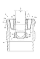
次に、発明を実施するための形態を説明する。なお、以下の実施例では、図1の矢印X方向をボトルキャップ1の上下方向(軸方向)とする。   Next, modes for carrying out the invention will be described. In the following embodiment, the direction of arrow X in FIG. 1 is the vertical direction (axial direction) of the bottle cap 1.

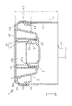
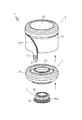
図1乃至図5に示すように、本実施例のボトルキャップ1は、ウォーターサーバー用液体容器の筒状口部10に着脱可能に装着されるキャップ部材であって、具体的には、中央部にウォーターサーバーの給水軸11が挿入される軸受部21が形成され、筒状口部10に水密状態で嵌合される本体部材2と、軸受部21の液体容器側の開口端に嵌脱可能に保持されるインナー部材3と、本体部材2が内部空間内に嵌合されて一体に組み付けられるカバー部材4等とを具備してなるカバー付きボトルキャップとして構成されている。   As shown in FIGS. 1 to 5, the bottle cap 1 of this embodiment is a cap member that is detachably attached to the cylindrical mouth portion 10 of the water container for a water server. A bearing portion 21 into which the water supply shaft 11 of the water server is inserted is formed, and the body member 2 fitted into the cylindrical mouth portion 10 in a watertight state can be fitted into and removed from the opening end of the bearing portion 21 on the liquid container side. The bottle member with a cover is configured to include an inner member 3 held by the cover member 4 and a cover member 4 or the like in which the main body member 2 is fitted into the internal space and assembled together.

筒状口部10は、飲料水等の液体が充填されたカートリッジ容器として構成される液体容器(図略)の一側に突出されており、筒状口部10に本体部材2が装着された状態でウォーターサーバーに液体容器が連結される(図5参照)。筒状口部10の開口端は、緩やかなR形状に面取りされ、外周側より径方向に突出された突起部12が形成されており、筒状口部10にボトルキャップ1が容易に装着できるように構成されている。突起部12は、筒状口部10にボトルキャップ1が装着された状態で、後述する本体部材2に形成される装着凹部22aと嵌合される。   The cylindrical mouth portion 10 protrudes to one side of a liquid container (not shown) configured as a cartridge container filled with a liquid such as drinking water, and the main body member 2 is attached to the tubular mouth portion 10. In this state, the liquid container is connected to the water server (see FIG. 5). The opening end of the cylindrical mouth portion 10 is chamfered into a gentle R shape, and a protruding portion 12 that protrudes in the radial direction from the outer peripheral side is formed. The bottle cap 1 can be easily attached to the cylindrical mouth portion 10. It is configured as follows. The protrusion 12 is fitted to a mounting recess 22a formed in the main body member 2 described later in a state where the bottle cap 1 is mounted on the cylindrical mouth portion 10.

本体部材2は、天面20の中央部に形成された筒状の軸受部21と、天面20の周縁に形成される外縁部22等とが一体形成されて構成されている。軸受部21は、天面20と連続される断面円形筒状の外筒部23と、天面20と連続され外筒部23の径方向内側位置に配設される断面円形筒状の内筒部24とで構成され、内部に給水軸11が挿入される軸孔21aが形成されている。   The main body member 2 is configured by integrally forming a cylindrical bearing portion 21 formed at the center of the top surface 20 and an outer edge portion 22 formed at the periphery of the top surface 20. The bearing portion 21 includes an outer cylinder portion 23 having a circular cross section that is continuous with the top surface 20, and an inner cylinder having a circular cross section that is continuous with the top surface 20 and disposed at a radially inner position of the outer cylinder portion 23. A shaft hole 21a into which the water supply shaft 11 is inserted is formed.

軸受部21は、天面20に内筒部24が開口されるとともに、天面20の反対側である液体容器側(図1の下方側)の開口端に外筒部23及び内筒部24が開口される。軸受部21は、天面20に開口された内筒部24より軸孔21a内に給水軸11が挿入され、外筒部23及び内筒部24の開口端より突出される。また、軸受部21は、外筒部23の液体容器側の開口端に後述するインナー部材3が水密状態で嵌脱可能に保持され、インナー部材3により軸孔21aが閉止されている。   The bearing portion 21 has an inner tube portion 24 opened on the top surface 20 and an outer tube portion 23 and an inner tube portion 24 at the opening end on the liquid container side (the lower side in FIG. 1) opposite to the top surface 20. Is opened. The bearing portion 21 has the water supply shaft 11 inserted into the shaft hole 21 a from the inner tube portion 24 opened in the top surface 20, and protrudes from the open ends of the outer tube portion 23 and the inner tube portion 24. In addition, the bearing portion 21 is held at the opening end of the outer cylinder portion 23 on the liquid container side so that an inner member 3 (described later) can be fitted and removed in a watertight state, and the shaft hole 21 a is closed by the inner member 3.

外筒部23は、天面20より給水軸11の挿入方向(図1の矢印上下方向)に沿って筒状に延出され、液体容器側の開口端の内周面がインナー部材3(の止水リブ33)と圧接される。外筒部23の液体容器側の開口端より挿入されたインナー部材3は、液体容器側の開口端の内周面と圧接されることで(止水33リブが)弾性変形し、外筒部23の液体容器側の開口端に水密状態で嵌合される(図2等参照)。このように、本実施例の軸受部21では、外筒部23にてインナー部材3が止水保持される。   The outer cylinder portion 23 extends in a cylindrical shape from the top surface 20 along the insertion direction of the water supply shaft 11 (the arrow vertical direction in FIG. 1), and the inner peripheral surface of the opening end on the liquid container side is the inner member 3 (of the inner member 3). The water stop rib 33) is pressed. The inner member 3 inserted from the opening end on the liquid container side of the outer cylinder portion 23 is elastically deformed (the water stop 33 rib) is elastically deformed by being pressed against the inner peripheral surface of the opening end on the liquid container side. 23 is fitted in a watertight state to the open end of the liquid container 23 (see FIG. 2 and the like). Thus, in the bearing portion 21 of the present embodiment, the inner member 3 is held water-stopped by the outer tube portion 23.

外筒部23は、液体容器側の開口端の外周面が側方に向けて延出される周壁部と連続され、周壁部を介して後述する周縁鍔26と連続されている。このように周壁部が形成されることで、天面20には円周方向に沿って液体容器側に向けた凹状溝が形成される。   The outer cylinder portion 23 is continuous with a peripheral wall portion extending outwardly from the outer peripheral surface of the opening end on the liquid container side, and is continued with a peripheral flange 26 described later via the peripheral wall portion. By forming the peripheral wall portion in this way, a concave groove is formed on the top surface 20 toward the liquid container along the circumferential direction.

内筒部24は、天面20より給水軸11の挿入方向に沿って筒状に延出され、液体容器側の開口端の内周面に給水軸11の外周面と圧接される止水リブ24aが形成されている。止水リブ24aが内筒部24の内部空間に挿入された給水軸11と圧接されることで(図5参照)、液体容器側の開口端が拡径方向に弾性変形され、内筒部24と給水軸11の外周面とが水密状態で圧着される。このように、本実施例の軸受部21では、内筒部24にて給水軸11が止水保持される。   The inner cylinder portion 24 extends in a cylindrical shape from the top surface 20 along the insertion direction of the water supply shaft 11, and is a water blocking rib that is in pressure contact with the outer peripheral surface of the water supply shaft 11 on the inner peripheral surface of the opening end on the liquid container side. 24a is formed. The water stop rib 24a is pressed into contact with the water supply shaft 11 inserted into the inner space of the inner cylinder portion 24 (see FIG. 5), so that the opening end on the liquid container side is elastically deformed in the diameter increasing direction, and the inner cylinder portion 24 And the outer peripheral surface of the water supply shaft 11 are pressure-bonded in a watertight state. Thus, in the bearing portion 21 of the present embodiment, the water supply shaft 11 is held water-stopped by the inner cylinder portion 24.

本実施例の軸受部21は、内筒部24が外筒部23の径方向内側位置に配設されることで、外筒部23及び内筒部24により二重筒状構造が形成され、内筒部24の液体容器側の開口端が外筒部23の開口端よりも突出しないように形成されるとともに、外筒部23及び内筒部24が径方向に相互に離間を有するように形成されている。   In the bearing portion 21 of the present embodiment, the inner cylindrical portion 24 is disposed at a radially inner position of the outer cylindrical portion 23, so that a double cylindrical structure is formed by the outer cylindrical portion 23 and the inner cylindrical portion 24. The opening end on the liquid container side of the inner cylinder part 24 is formed so as not to protrude from the opening end of the outer cylinder part 23, and the outer cylinder part 23 and the inner cylinder part 24 are spaced apart from each other in the radial direction. Is formed.

外縁部22は、天面20の周縁より給水軸11の挿入方向に沿って延出され、内周面に筒状口部10の突起部12が嵌合される装着凹部22aが円周方向に沿って形成されている。また、外縁部22は、外周面に筒状口部10より本体部材2を脱離させる工具(例えば、デキャッパ等)と係合される段差部22bが形成されている。段差部22bは、下向きの水平面を有する切欠き状の段差として円周方向に沿って形成されている。   The outer edge portion 22 extends from the peripheral edge of the top surface 20 along the insertion direction of the water supply shaft 11, and a mounting recess 22 a in which the protruding portion 12 of the cylindrical mouth portion 10 is fitted to the inner peripheral surface is provided in the circumferential direction. Are formed along. Further, the outer edge portion 22 is formed with a stepped portion 22b that is engaged with a tool (for example, a decapper or the like) for removing the main body member 2 from the cylindrical mouth portion 10 on the outer peripheral surface. The step portion 22b is formed along the circumferential direction as a notch-shaped step having a downward horizontal surface.

軸受部21と外縁部22との間には、天面20より給水軸11の挿入方向に沿って周縁鍔26が立設され、周縁鍔26の外周面には係止リブ26aが円周方向に沿って形成されている。   Between the bearing portion 21 and the outer edge portion 22, a peripheral flange 26 is erected along the insertion direction of the water supply shaft 11 from the top surface 20, and a locking rib 26 a is circumferentially provided on the outer peripheral surface of the peripheral flange 26. It is formed along.

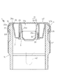
本体部材2が筒状口部10に装着された状態(図3及び図4参照)では、筒状口部10の開口端(突起部12)が外縁部22の内周面と周縁鍔26の外周面との離間に挿入されて装着凹部22aに嵌合される。その際、筒状口部10の開口端(突起部12)の形状に合わせて外縁部22が弾性変形されるとともに、止水リブ26aが筒状口部10の内周面に圧接されることで、外縁部22の内周面と周縁鍔26の外周面とで筒状口部10が挟圧され、筒状口部10に本体部材2が水密状態で嵌合される。   In a state where the main body member 2 is mounted on the cylindrical mouth portion 10 (see FIGS. 3 and 4), the opening end (projection portion 12) of the cylindrical mouth portion 10 is formed between the inner peripheral surface of the outer edge portion 22 and the peripheral flange 26. It is inserted away from the outer peripheral surface and is fitted into the mounting recess 22a. At that time, the outer edge portion 22 is elastically deformed according to the shape of the opening end (projection portion 12) of the cylindrical mouth portion 10, and the water stop rib 26 a is pressed against the inner peripheral surface of the cylindrical mouth portion 10. Thus, the cylindrical mouth portion 10 is sandwiched between the inner peripheral surface of the outer edge portion 22 and the outer peripheral surface of the peripheral edge 26, and the main body member 2 is fitted into the cylindrical mouth portion 10 in a watertight state.

インナー部材3は、軸受部21の外筒部23の液体容器側の開口端を塞ぐようにして水密状態で嵌脱可能に保持され、具体的には、有底筒状の本体部30の外周に外周壁30aが形成され、外周壁30aの外周面に止水リブ33が円周方向に沿って延出されている。本体部30は、軸受部21の内部方向に向けて開口され、開口端が径方向内側に向けて屈曲されて、給水軸11の先端に形成される凹状部と係合可能に形成されている。また、止水リブ33は、上述したように、外筒部23の液体容器側の開口端にインナー部材3が保持された状態で外筒部23の内周面に圧接される。   The inner member 3 is detachably held in a watertight manner so as to close the liquid container side opening end of the outer cylindrical portion 23 of the bearing portion 21, and specifically, the outer periphery of the bottomed cylindrical main body portion 30. The outer peripheral wall 30a is formed in the outer peripheral wall 30a, and the water stop rib 33 is extended on the outer peripheral surface of the outer peripheral wall 30a along the circumferential direction. The main body portion 30 is opened toward the inner direction of the bearing portion 21, and the opening end is bent inward in the radial direction so as to be engageable with a concave portion formed at the tip of the water supply shaft 11. . Further, as described above, the water blocking rib 33 is pressed against the inner peripheral surface of the outer cylindrical portion 23 in a state where the inner member 3 is held at the opening end of the outer cylindrical portion 23 on the liquid container side.

カバー部材4は、本体部材2が一体に組み付けられた状態で筒状口部10に装着されるとともに、本体部材2を残して筒状口部10より完全に剥脱可能に形成されており、具体的には、平面視円形状の天面40と、天面40の周縁と連続されて断面円形の筒状に肉薄形成されたスカート部41等とが一体成形されて有天筒状に形成されている。   The cover member 4 is attached to the cylindrical mouth portion 10 in a state where the main body member 2 is integrally assembled, and is formed so as to be completely removable from the cylindrical mouth portion 10 while leaving the main body member 2. Specifically, a top surface 40 having a circular shape in plan view, and a skirt portion 41 and the like that are formed continuously with the periphery of the top surface 40 and are thinly formed in a cylindrical shape having a circular cross section are integrally formed to form a ceiling tube shape. ing.

天面40は、平面視円形状に形成され、少なくとも直径が同じく平面視円形に形成される本体部材2の天面20の直径よりも大きくなるように形成される。本体部材2及びカバー部材4が一体に組み付けられた状態(図1参照)で、天面40にて本体部材2の天面20の給水軸挿入側(図1の上方側)が完全に覆われて、本体部材2に開口された給水軸11の軸孔21aが閉止される。   The top surface 40 is formed in a circular shape in plan view, and is formed so that at least the diameter is larger than the diameter of the top surface 20 of the main body member 2 that is also formed in a circular shape in plan view. In a state where the main body member 2 and the cover member 4 are integrally assembled (see FIG. 1), the water supply shaft insertion side (upper side in FIG. 1) of the top surface 20 of the main body member 2 is completely covered with the top surface 40. Thus, the shaft hole 21a of the water supply shaft 11 opened in the main body member 2 is closed.

スカート部41は、内周面に天面40との連続箇所であるコーナー箇所に本体部材2(の外縁部22)が嵌合される係止凹部41aが円周方向に沿って形成されている。本実施例のボトルキャップ1は、カバー部材4のスカート部41の下方開口端より本体部材2が内部空間内に挿入され、スカート部材4の係止凹部41aに本体部材2の外縁部22が密接嵌合されることで、カバー部材4に本体部材2が一体に組み付けられる(図2等参照)。   As for the skirt part 41, the latching recessed part 41a with which the main body member 2 (outer edge part 22) is fitted is formed in the circumferential direction at the corner location which is a continuous location with the top | upper surface 40 on the inner peripheral surface. . In the bottle cap 1 of this embodiment, the main body member 2 is inserted into the inner space from the lower opening end of the skirt portion 41 of the cover member 4, and the outer edge portion 22 of the main body member 2 is in close contact with the locking recess 41 a of the skirt member 4. By fitting, the main body member 2 is integrally assembled to the cover member 4 (see FIG. 2 and the like).

スカート部41は、天面40から液体容器側の開口端までの軸方向長さL1が、本体部材2の外縁部22の天面20から液体容器側の開口端までの軸方向長さL2よりも長くなるように形成され、液体容器側の開口端から外縁部22の開口端が突出しないように形成される(図1等参照)。本体部材2及びカバー部材4が一体に組み付けられた状態(図1等参照)で、スカート部41にて外縁部22の径方向外側が完全に覆われて、カバー部材4にて本体部材2の天面20の給水軸挿入側、及び外縁部22の径方向外側が囲繞される。   The skirt portion 41 has an axial length L1 from the top surface 40 to the opening end on the liquid container side, and an axial length L2 from the top surface 20 of the outer edge portion 22 of the main body member 2 to the opening end on the liquid container side. Also, the opening end of the outer edge portion 22 does not protrude from the opening end on the liquid container side (see FIG. 1 and the like). In a state where the main body member 2 and the cover member 4 are assembled together (see FIG. 1 and the like), the outer side in the radial direction of the outer edge portion 22 is completely covered with the skirt portion 41, and the cover member 4 covers the main body member 2. The water supply shaft insertion side of the top surface 20 and the radially outer side of the outer edge portion 22 are surrounded.

また、スカート部41は、外周面に軸方向及び円周方向に連続して延出される一つの凹溝41bが形成される。凹溝41bは、スカート部41の開口端より天面40へ向けて湾曲しながら延出され、中途部にて円周方向に向けられて、略全周に渡って延出されるようにして形成される。スカート部41の開口端の縁部には、舌状の把持片42が形成され、かかる把持片42が天面40の方向に引き上げられることで、凹溝41bに沿ってスカート部41が破断される。   In addition, the skirt portion 41 is formed with one concave groove 41b extending continuously in the axial direction and the circumferential direction on the outer peripheral surface. The concave groove 41b extends while curving from the open end of the skirt portion 41 toward the top surface 40, and is formed so as to extend in the circumferential direction at the midway portion and extend over substantially the entire circumference. Is done. A tongue-shaped grip piece 42 is formed at the edge of the open end of the skirt portion 41, and the grip piece 42 is pulled up in the direction of the top surface 40, whereby the skirt portion 41 is broken along the concave groove 41b. The

次に、図3乃至図5を参照して、ウォーターサーバーにボトルキャップ1が装着された液体容器を連結する際の動作について、以下に詳述する。   Next, with reference to FIG. 3 to FIG. 5, the operation when connecting the liquid container with the bottle cap 1 attached to the water server will be described in detail below.

まず、ウォーターサーバーに連結される前の液体容器には、筒状口部10の開口端(突起部12)に予め本体部材2及びカバー部材4が一体に組み付けられたボトルキャップ1が装着される。すなわち、筒状口部10内に軸受部21が突出された状態で本体部材2が筒状口部10の外周側に水密状態で嵌合され、その上から本体部材2を完全に覆うようにしてカバー部材4が筒状口部10に固定される(図3参照)。なお、かかる状態では、カバー部材4は、スカート部41が筒状口部10の外周面に圧着されている。   First, the bottle cap 1 in which the main body member 2 and the cover member 4 are integrally assembled in advance is attached to the opening end (protrusion portion 12) of the cylindrical mouth portion 10 before being connected to the water server. . That is, the main body member 2 is fitted in a watertight state on the outer peripheral side of the cylindrical mouth portion 10 with the bearing portion 21 protruding into the cylindrical mouth portion 10, and the main body member 2 is completely covered from above. The cover member 4 is fixed to the cylindrical mouth portion 10 (see FIG. 3). In this state, the cover member 4 has the skirt portion 41 crimped to the outer peripheral surface of the cylindrical mouth portion 10.

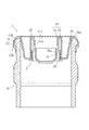
ウォーターサーバーに液体容器を連結する際には、まず、カバー部材4において、把持片42が引き上げられて凹溝41bに沿ってスカート部41が破断されることで、本体部材2を残したままで筒状口部10よりカバー部材4が完全に剥脱される(図4参照)。かかる状態では、本体部材2は筒状口部10に水密状態で嵌合されたままで、天面20及び外縁部22が露出される。   When connecting the liquid container to the water server, first, in the cover member 4, the gripping piece 42 is pulled up and the skirt portion 41 is broken along the concave groove 41b. The cover member 4 is completely peeled off from the opening 10 (see FIG. 4). In such a state, the top surface 20 and the outer edge portion 22 are exposed while the main body member 2 remains fitted to the cylindrical mouth portion 10 in a watertight state.

次いで、ウォーターサーバーの上方より液体容器を下動させ、本体部材2の天面20に露出している軸孔21aより内筒部24内に給水軸11を挿入する。内筒部24に挿入された給水軸11は、内筒部24の液体容器側の開口端を拡径方向に弾性変形させながら止水リブ24aと圧接され、外周面が内筒部24と水密状態で圧着された状態で挿通されていく。そして、給水軸11の先端部が外筒部23の開口端に水密状態で嵌合されたインナー部材3に当接すると、液体容器の下動に伴って外筒部23に対してインナー部材3を押し上げながら、給水軸11の先端部がインナー部材3の開口端に嵌挿されて給水軸11とインナー部材3とが一体とされ、やがて、外筒部23及び内筒部24の液体容器側の開口端より給水軸11が突出される(図5参照)。   Next, the liquid container is moved downward from above the water server, and the water supply shaft 11 is inserted into the inner cylinder portion 24 through the shaft hole 21 a exposed on the top surface 20 of the main body member 2. The water supply shaft 11 inserted into the inner cylinder portion 24 is pressed against the water stop rib 24a while elastically deforming the opening end of the inner cylinder portion 24 on the liquid container side in the diameter increasing direction, and the outer peripheral surface is watertight with the inner cylinder portion 24. It is inserted in a state where it is crimped. And if the front-end | tip part of the water supply axis | shaft 11 contact | abuts to the inner member 3 fitted to the opening end of the outer cylinder part 23 in the watertight state, the inner member 3 will be with respect to the outer cylinder part 23 with a downward movement of a liquid container. While pushing up, the tip of the water supply shaft 11 is inserted into the opening end of the inner member 3 so that the water supply shaft 11 and the inner member 3 are integrated, and eventually the liquid container side of the outer cylinder portion 23 and the inner cylinder portion 24 The water supply shaft 11 is protruded from the opening end (see FIG. 5).

以上のように、本実施例のボトルキャップ1は、ウォーターサーバー用液体容器の筒状口部10に装着されて用いられるボトルキャップ1において、中央部にウォーターサーバーの給水軸11が挿入される軸受部21が形成され、筒状口部10に水密状態で嵌合される本体部材2と、本体部材2が内部空間内に嵌合されて一体に組み付けられるカバー部材4と、を具備してなり、カバー部材4は、本体部材2が一体に組み付けられた状態で筒状口部10に装着され、本体部材2を残して筒状口部10より完全に剥脱可能に形成されるため、簡易な構成で衛生管理及び品質保持を容易にし、かつ液体容器内の内容物の品質改竄を防止して未開封性を向上できるのである。   As described above, the bottle cap 1 of the present embodiment is a bearing in which the water supply shaft 11 of the water server is inserted in the center of the bottle cap 1 used by being mounted on the cylindrical mouth portion 10 of the liquid container for water server. A body member 2 that is formed with a portion 21 and is fitted into the cylindrical mouth portion 10 in a watertight manner, and a cover member 4 that is fitted into the internal space and assembled together. The cover member 4 is attached to the cylindrical mouth portion 10 in a state in which the main body member 2 is integrally assembled, and is formed so as to be completely removable from the cylindrical mouth portion 10 leaving the main body member 2. The structure facilitates hygiene management and quality maintenance, and prevents the quality of the contents in the liquid container from being tampered with, thereby improving the unopened property.

すなわち、有天筒状のカバー部材4の内部空間内に本体部材2が一体に組み付けられたカバー付きボトルキャップとして構成し、本体部材2が一体に組み付けられた状態で筒状口部10に装着し、本体部材2を残して筒状口部10より完全に剥脱可能に形成することで、液体容器を搬送・保管する際の衛生管理や、本体部材2の天面20に開口される軸孔21aより塵埃や虫等が異物混入を防止することによる品質保持が容易となり、また、液体容器内の内容物の品質改竄を確実に防止できるので未開封性を向上できる。さらに、従来のボトルキャップのようにシールラベルやシュリンクフィルムが不要となるため、従来の構成と比べて簡易な構成で製造コストを低減できる。   That is, it is configured as a bottle cap with a cover in which the main body member 2 is integrally assembled in the inner space of the lenticular cylindrical cover member 4, and is attached to the cylindrical mouth portion 10 in a state where the main body member 2 is integrally assembled. Then, by leaving the main body member 2 so as to be completely removable from the cylindrical mouth portion 10, hygiene management when transporting and storing the liquid container, and a shaft hole opened in the top surface 20 of the main body member 2 From 21a, it becomes easy to maintain the quality by preventing foreign matters from being mixed with dust, insects and the like, and the quality of the contents in the liquid container can be surely prevented, so that the unopenability can be improved. Further, since a seal label and a shrink film are not required as in the case of a conventional bottle cap, the manufacturing cost can be reduced with a simple configuration compared to the conventional configuration.

特に、カバー部材4は、平面視円形状の天面40と、天面40の周縁と連続される筒状のスカート部41とを有してなる有天筒状に形成され、本体部材2が組み付けられた状態で本体部材2の天面20及び外縁部22が囲繞されるため、液体容器の筒状口部10に装着された状態でカバー部材4により本体部材2の天面20及び外縁部22が露出しないので、カバー部材4にて本体部材2を完全に被覆することで衛生管理及び品質保持をより向上できる。   In particular, the cover member 4 is formed in a cylindrical shape having a top surface 40 having a circular shape in plan view and a cylindrical skirt portion 41 continuous with the periphery of the top surface 40, and the body member 2 is Since the top surface 20 and the outer edge portion 22 of the main body member 2 are enclosed in the assembled state, the top surface 20 and the outer edge portion of the main body member 2 are covered by the cover member 4 while being attached to the cylindrical mouth portion 10 of the liquid container. Since 22 is not exposed, sanitary management and quality maintenance can be further improved by completely covering the main body member 2 with the cover member 4.

また、カバー部材4は、スカート部41の軸方向長さL1が本体部材2の外縁部22の軸方向長さL2よりも長くなるように形成されるため、液体容器の筒状口部10に装着された状態で、スカート部41にて外縁部22だけでなく筒状口部10の外周面の一部を被覆することで衛生管理及び品質保持をより向上できる。   Further, since the cover member 4 is formed such that the axial length L1 of the skirt portion 41 is longer than the axial length L2 of the outer edge portion 22 of the main body member 2, the cover member 4 is formed in the cylindrical mouth portion 10 of the liquid container. In the mounted state, the skirt portion 41 covers not only the outer edge portion 22 but also a part of the outer peripheral surface of the cylindrical mouth portion 10, so that hygiene management and quality maintenance can be further improved.

また、カバー部材4は、スカート部41の外周面に軸方向及び円周方向に連続して延出される凹溝41bが形成され、凹溝41bに沿ってスカート部41が破断されるため、カバー部材4のみを筒状口部11より容易に剥脱させることができる。   Further, the cover member 4 has a concave groove 41b extending continuously in the axial direction and the circumferential direction on the outer peripheral surface of the skirt portion 41, and the skirt portion 41 is broken along the concave groove 41b. Only the member 4 can be easily detached from the cylindrical mouth portion 11.

なお、ボトルキャップ1の構成としては、上述した実施例に限定されず、本発明の目的を逸脱しない限りにおいて種々の変更が可能である。   In addition, as a structure of the bottle cap 1, it is not limited to the Example mentioned above, A various change is possible unless it deviates from the objective of this invention.

すなわち、上述した実施例のボトルキャップ1では、カバー部材4の係止凹部41aに本体部材2の外縁部22が密接嵌合されることで、カバー部材4に本体部材2が一体に組み付けられる構成について説明したが、本体部材2とカバー部材との組み付け構成はこれに限定されず、カバー部材4の下方開口端より本体部材2が内部空間内に挿入されて組み付けられる構成であればよい。   That is, in the bottle cap 1 of the above-described embodiment, the main body member 2 is integrally assembled to the cover member 4 by closely fitting the outer edge portion 22 of the main body member 2 to the locking recess 41 a of the cover member 4. However, the assembly structure of the main body member 2 and the cover member is not limited to this, and any structure may be used as long as the main body member 2 is inserted into the internal space from the lower opening end of the cover member 4.

また、上述した実施例では、カバー部材4の外周面に軸方向及び円周方向に連続して延出される一つの凹溝41bが形成される構成について説明したが、カバー部材4における凹溝部41bの構成はこれに限定されず、例えば、凹溝41bが天面40まで延出されるか、または2つ以上の複数の凹溝より形成されるか等して、凹溝41bに沿って天面41又はスカート部41が破断されることで本体部材2を残してカバー部材4を容易に剥脱できる構成であればよい。   In the above-described embodiment, the configuration in which one concave groove 41 b extending continuously in the axial direction and the circumferential direction is formed on the outer peripheral surface of the cover member 4 is described. However, the concave groove portion 41 b in the cover member 4 is described. The configuration of is not limited to this, for example, the top surface along the concave groove 41b, for example, whether the concave groove 41b extends to the top surface 40 or is formed of two or more concave grooves. 41 or the skirt portion 41 may be broken so long as the cover member 4 can be easily peeled off while leaving the main body member 2.

1 ボトルキャップ
2 本体部材
3 インナー部材
10 筒状口部
11 給水軸
12 突起部
20 天面
21 軸受部
22 外縁部
22a 装着凹部
23 外筒部
24 内筒部
24a 止水リブ
26 周縁鍔
26a 止水リブ
30 本体部
33 止水リブ
40 天面
41 スカート部
41a 係止凹部
41b 凹溝
42 把持片
DESCRIPTION OF SYMBOLS 1 Bottle cap 2 Main body member 3 Inner member 10 Cylindrical mouth part 11 Water supply shaft 12 Protrusion part 20 Top surface 21 Bearing part 22 Outer edge part 22a Mounting recessed part 23 Outer cylinder part 24 Inner cylinder part 24a Water stop rib 26 Peripheral collar 26a Water stop Rib 30 Body 33 Water-stop rib 40 Top 41 Skirt 41a Locking recess 41b Groove 42 Holding piece

Claims (3)

ウォーターサーバー用液体容器の筒状口部に装着されて用いられるボトルキャップにおいて、
中央部にウォーターサーバーの給水軸が挿入される軸受部が形成され、天面の周縁より延出される外縁部の内周面が圧接されて前記筒状口部に水密状態で嵌合される本体部材と、
平面視円形状の天面と、前記天面の周縁と連続され筒状に肉薄形成されたスカート部と、前記スカート部の内周面の天面との連続箇所に形成される係止凹部とを有してなる有底筒状に形成され、前記係止凹部に前記本体部材の外縁部が密接嵌合されて前記本体部材が内部空間内に嵌合され、前記本体部材の天面及び外縁部が囲繞されて一体に組み付けられるカバー部材と、
を具備してなり、
前記カバー部材は、前記本体部材が一体に組み付けられた状態で、前記本体部材の外縁部が前記筒状口部の開口端の形状に合わせて弾性変形され、かつ前記スカート部が前記筒状口部に圧着されて装着され、前記本体部材を残して前記筒状口部より完全に剥脱可能に形成される、
ことを特徴とするボトルキャップ。
In the bottle cap that is used by being attached to the cylindrical mouth of the liquid container for water server,
The main body is formed with a bearing portion into which the water supply shaft of the water server is inserted at the center, and the inner peripheral surface of the outer edge portion extending from the peripheral edge of the top surface is pressed into contact with the cylindrical mouth portion in a watertight state. Members,
A top surface having a circular shape in plan view, a skirt portion that is continuous with the peripheral edge of the top surface and formed thin in a cylindrical shape, and a locking recess formed at a continuous location with the top surface of the inner peripheral surface of the skirt portion; The outer edge portion of the main body member is closely fitted to the locking recess and the main body member is fitted into the inner space, and the top surface and the outer edge of the main body member are formed. A cover member whose part is enclosed and assembled together;
Comprising
The cover member is elastically deformed in accordance with the shape of the opening end of the cylindrical mouth portion, and the skirt portion is the cylindrical mouth in a state where the body member is assembled integrally. It is crimped and attached to the part, and is formed so as to be completely removable from the cylindrical mouth part, leaving the body member.
A bottle cap characterized by that.
前記カバー部材は、前記スカート部の軸方向長さが前記本体部材の外縁部の軸方向長さよりも長くなるように形成される請求項1に記載のボトルキャップ。   The bottle cap according to claim 1, wherein the cover member is formed such that an axial length of the skirt portion is longer than an axial length of an outer edge portion of the main body member. 前記カバー部材は、前記スカート部の外周面に軸方向及び円周方向に連続して延出される凹溝が形成され、前記凹溝に沿って前記スカート部が破断される請求項1又は請求項2に記載のボトルキャップ。   2. The cover member according to claim 1, wherein a concave groove extending continuously in an axial direction and a circumferential direction is formed on an outer peripheral surface of the skirt portion, and the skirt portion is broken along the concave groove. 2. The bottle cap according to 2.
JP2015034617A 2015-02-24 2015-02-24 Bottle cap Active JP6571347B2 (en)

Priority Applications (1)

Application Number Priority Date Filing Date Title
JP2015034617A JP6571347B2 (en) 2015-02-24 2015-02-24 Bottle cap

Applications Claiming Priority (1)

Application Number Priority Date Filing Date Title
JP2015034617A JP6571347B2 (en) 2015-02-24 2015-02-24 Bottle cap

Publications (2)

Publication Number Publication Date
JP2016155570A JP2016155570A (en) 2016-09-01
JP6571347B2 true JP6571347B2 (en) 2019-09-04

Family

ID=56824835

Family Applications (1)

Application Number Title Priority Date Filing Date
JP2015034617A Active JP6571347B2 (en) 2015-02-24 2015-02-24 Bottle cap

Country Status (1)

Country Link
JP (1) JP6571347B2 (en)

Family Cites Families (7)

* Cited by examiner, † Cited by third party
Publication number Priority date Publication date Assignee Title
JPH08301333A (en) * 1995-05-10 1996-11-19 Kita Sangyo Kk Synthetic resin made cap
JP2009001315A (en) * 2007-06-22 2009-01-08 Sahara Kagaku Kogyo Kk Container for drinking water
JP4898886B2 (en) * 2009-09-17 2012-03-21 石田金型製作所有限会社 Cap for beverage dispenser, beverage dispenser container equipped with the same, beverage dispenser system, and cap manufacturing apparatus and method
JP2010089842A (en) * 2010-01-27 2010-04-22 Helthy Water Co Ltd Lid for liquid container
JP5009435B1 (en) * 2011-08-18 2012-08-22 康仁 河島 Bottle cap
JP5791014B2 (en) * 2012-08-29 2015-10-07 きた産業株式会社 Cap for bottle
CN203111702U (en) * 2013-02-22 2013-08-07 广西巴马丽琅饮料有限公司 Dual-purpose bottle cap

Also Published As

Publication number Publication date
JP2016155570A (en) 2016-09-01

Similar Documents

Publication Publication Date Title
RU2354597C2 (en) Valve locking device
JP2019182539A (en) Bottle cap
JP5009435B1 (en) Bottle cap
JP2014510681A (en) Device for capping the neck of a container
JP5746947B2 (en) Refill container and double container
JP6290613B2 (en) Plastic cap
JP2015209234A (en) Hinge cap
JP5193895B2 (en) Double container
US10604306B2 (en) Assembled container cap
JP6571347B2 (en) Bottle cap
JP2014091524A (en) Cap
JP3971309B2 (en) Metal crimp cap for fluid dispenser device
JP2016155569A (en) Bottle cap
JP5483435B2 (en) Plug
JP5940364B2 (en) Hinge cap
KR101899326B1 (en) Assembled container cap
US10889485B2 (en) Dispensing system including a dispensing tap and an integrated measuring cap/cup and holder
WO2014192621A1 (en) Shoulder cover for aerosol container
JP5368336B2 (en) Container with cap
JP4929627B2 (en) cap
JP7246831B2 (en) pouring cap
JP2020104916A (en) container
US20090084792A1 (en) Container Cap with Airtight Device
KR200354302Y1 (en) A bottle covering apparatus
JP2008296983A (en) Pouring cap

Legal Events

Date Code Title Description
A621 Written request for application examination

Free format text: JAPANESE INTERMEDIATE CODE: A621

Effective date: 20180202

A977 Report on retrieval

Free format text: JAPANESE INTERMEDIATE CODE: A971007

Effective date: 20181116

A131 Notification of reasons for refusal

Free format text: JAPANESE INTERMEDIATE CODE: A131

Effective date: 20181219

A521 Request for written amendment filed

Free format text: JAPANESE INTERMEDIATE CODE: A523

Effective date: 20190216

TRDD Decision of grant or rejection written
A01 Written decision to grant a patent or to grant a registration (utility model)

Free format text: JAPANESE INTERMEDIATE CODE: A01

Effective date: 20190806

A61 First payment of annual fees (during grant procedure)

Free format text: JAPANESE INTERMEDIATE CODE: A61

Effective date: 20190808

R150 Certificate of patent or registration of utility model

Ref document number: 6571347

Country of ref document: JP

Free format text: JAPANESE INTERMEDIATE CODE: R150

R250 Receipt of annual fees

Free format text: JAPANESE INTERMEDIATE CODE: R250