JP6570621B2 - Fluid injection nozzle for fluidized bed reactor - Google Patents
Fluid injection nozzle for fluidized bed reactor Download PDFInfo
- Publication number
- JP6570621B2 JP6570621B2 JP2017511628A JP2017511628A JP6570621B2 JP 6570621 B2 JP6570621 B2 JP 6570621B2 JP 2017511628 A JP2017511628 A JP 2017511628A JP 2017511628 A JP2017511628 A JP 2017511628A JP 6570621 B2 JP6570621 B2 JP 6570621B2
- Authority
- JP
- Japan
- Prior art keywords
- reactor
- premixer
- section
- flow
- liquid
- Prior art date
- Legal status (The legal status is an assumption and is not a legal conclusion. Google has not performed a legal analysis and makes no representation as to the accuracy of the status listed.)
- Expired - Fee Related
Links
- 239000012530 fluid Substances 0.000 title claims description 43
- 238000002347 injection Methods 0.000 title claims description 20
- 239000007924 injection Substances 0.000 title claims description 20
- 239000007788 liquid Substances 0.000 claims description 112
- 239000000571 coke Substances 0.000 claims description 84
- 238000004939 coking Methods 0.000 claims description 59
- 239000002245 particle Substances 0.000 claims description 47
- 239000000203 mixture Substances 0.000 claims description 45
- 239000002994 raw material Substances 0.000 claims description 41
- 238000006243 chemical reaction Methods 0.000 claims description 38
- 239000000295 fuel oil Substances 0.000 claims description 38
- 239000003921 oil Substances 0.000 claims description 32
- 239000007787 solid Substances 0.000 claims description 26
- 238000009792 diffusion process Methods 0.000 claims description 13
- 238000000429 assembly Methods 0.000 claims description 6
- 230000000712 assembly Effects 0.000 claims description 6
- 238000012546 transfer Methods 0.000 claims description 6
- 230000002093 peripheral effect Effects 0.000 claims description 3
- 238000007599 discharging Methods 0.000 claims description 2
- 239000007789 gas Substances 0.000 description 34
- 239000007921 spray Substances 0.000 description 27
- 238000002156 mixing Methods 0.000 description 17
- 238000004140 cleaning Methods 0.000 description 11
- 238000000034 method Methods 0.000 description 11
- 230000008569 process Effects 0.000 description 11
- 239000000047 product Substances 0.000 description 11
- 239000010426 asphalt Substances 0.000 description 10
- 238000000889 atomisation Methods 0.000 description 10
- 230000003628 erosive effect Effects 0.000 description 10
- 239000004215 Carbon black (E152) Substances 0.000 description 9
- 229930195733 hydrocarbon Natural products 0.000 description 9
- 150000002430 hydrocarbons Chemical class 0.000 description 9
- 238000011144 upstream manufacturing Methods 0.000 description 9
- 230000006872 improvement Effects 0.000 description 8
- 239000000463 material Substances 0.000 description 8
- 230000008602 contraction Effects 0.000 description 7
- 241000219793 Trifolium Species 0.000 description 6
- 239000012071 phase Substances 0.000 description 6
- 230000001133 acceleration Effects 0.000 description 5
- 238000013459 approach Methods 0.000 description 5
- 230000010349 pulsation Effects 0.000 description 5
- 239000003381 stabilizer Substances 0.000 description 5
- 230000015572 biosynthetic process Effects 0.000 description 4
- 238000013461 design Methods 0.000 description 4
- 239000006185 dispersion Substances 0.000 description 4
- 239000006260 foam Substances 0.000 description 4
- 239000012263 liquid product Substances 0.000 description 4
- 238000012360 testing method Methods 0.000 description 4
- MWUXSHHQAYIFBG-UHFFFAOYSA-N Nitric oxide Chemical compound O=[N] MWUXSHHQAYIFBG-UHFFFAOYSA-N 0.000 description 3
- 208000031481 Pathologic Constriction Diseases 0.000 description 3
- 230000007423 decrease Effects 0.000 description 3
- 239000003208 petroleum Substances 0.000 description 3
- 238000000197 pyrolysis Methods 0.000 description 3
- 208000037804 stenosis Diseases 0.000 description 3
- 230000036262 stenosis Effects 0.000 description 3
- 239000012808 vapor phase Substances 0.000 description 3
- IJGRMHOSHXDMSA-UHFFFAOYSA-N Atomic nitrogen Chemical compound N#N IJGRMHOSHXDMSA-UHFFFAOYSA-N 0.000 description 2
- XEEYBQQBJWHFJM-UHFFFAOYSA-N Iron Chemical compound [Fe] XEEYBQQBJWHFJM-UHFFFAOYSA-N 0.000 description 2
- PXHVJJICTQNCMI-UHFFFAOYSA-N Nickel Chemical compound [Ni] PXHVJJICTQNCMI-UHFFFAOYSA-N 0.000 description 2
- 238000010793 Steam injection (oil industry) Methods 0.000 description 2
- NINIDFKCEFEMDL-UHFFFAOYSA-N Sulfur Chemical compound [S] NINIDFKCEFEMDL-UHFFFAOYSA-N 0.000 description 2
- QVGXLLKOCUKJST-UHFFFAOYSA-N atomic oxygen Chemical compound [O] QVGXLLKOCUKJST-UHFFFAOYSA-N 0.000 description 2
- 239000003245 coal Substances 0.000 description 2
- 238000000354 decomposition reaction Methods 0.000 description 2
- 230000002950 deficient Effects 0.000 description 2
- 238000001035 drying Methods 0.000 description 2
- 238000005243 fluidization Methods 0.000 description 2
- 230000007246 mechanism Effects 0.000 description 2
- 239000012528 membrane Substances 0.000 description 2
- 229910052760 oxygen Inorganic materials 0.000 description 2
- 239000001301 oxygen Substances 0.000 description 2
- 229910052698 phosphorus Inorganic materials 0.000 description 2
- 230000009467 reduction Effects 0.000 description 2
- 238000011160 research Methods 0.000 description 2
- 229910052717 sulfur Inorganic materials 0.000 description 2
- 239000011593 sulfur Substances 0.000 description 2
- 230000005514 two-phase flow Effects 0.000 description 2
- 238000009834 vaporization Methods 0.000 description 2
- 230000008016 vaporization Effects 0.000 description 2
- OKTJSMMVPCPJKN-UHFFFAOYSA-N Carbon Chemical compound [C] OKTJSMMVPCPJKN-UHFFFAOYSA-N 0.000 description 1
- 235000019738 Limestone Nutrition 0.000 description 1
- 241000736305 Marsilea quadrifolia Species 0.000 description 1
- 229910001347 Stellite Inorganic materials 0.000 description 1
- 230000001154 acute effect Effects 0.000 description 1
- 238000005054 agglomeration Methods 0.000 description 1
- 230000002776 aggregation Effects 0.000 description 1
- 150000001336 alkenes Chemical class 0.000 description 1
- 125000003118 aryl group Chemical group 0.000 description 1
- 230000002457 bidirectional effect Effects 0.000 description 1
- 229910052799 carbon Inorganic materials 0.000 description 1
- 230000015556 catabolic process Effects 0.000 description 1
- 238000004523 catalytic cracking Methods 0.000 description 1
- AHICWQREWHDHHF-UHFFFAOYSA-N chromium;cobalt;iron;manganese;methane;molybdenum;nickel;silicon;tungsten Chemical compound C.[Si].[Cr].[Mn].[Fe].[Co].[Ni].[Mo].[W] AHICWQREWHDHHF-UHFFFAOYSA-N 0.000 description 1
- 238000004891 communication Methods 0.000 description 1
- 238000001816 cooling Methods 0.000 description 1
- 238000005336 cracking Methods 0.000 description 1
- 238000006731 degradation reaction Methods 0.000 description 1
- 238000005516 engineering process Methods 0.000 description 1
- 239000000284 extract Substances 0.000 description 1
- 238000011049 filling Methods 0.000 description 1
- 230000004907 flux Effects 0.000 description 1
- 238000004508 fractional distillation Methods 0.000 description 1
- 239000000446 fuel Substances 0.000 description 1
- 239000002737 fuel gas Substances 0.000 description 1
- 238000002309 gasification Methods 0.000 description 1
- 230000005484 gravity Effects 0.000 description 1
- 238000010438 heat treatment Methods 0.000 description 1
- 238000001513 hot isostatic pressing Methods 0.000 description 1
- 239000001257 hydrogen Substances 0.000 description 1
- 229910052739 hydrogen Inorganic materials 0.000 description 1
- 125000004435 hydrogen atom Chemical class [H]* 0.000 description 1
- 230000006698 induction Effects 0.000 description 1
- 239000004615 ingredient Substances 0.000 description 1
- 230000003993 interaction Effects 0.000 description 1
- 229910052742 iron Inorganic materials 0.000 description 1
- 239000006028 limestone Substances 0.000 description 1
- 238000012423 maintenance Methods 0.000 description 1
- 238000005259 measurement Methods 0.000 description 1
- 229910052759 nickel Inorganic materials 0.000 description 1
- 229910052757 nitrogen Inorganic materials 0.000 description 1
- JRZJOMJEPLMPRA-UHFFFAOYSA-N olefin Natural products CCCCCCCC=C JRZJOMJEPLMPRA-UHFFFAOYSA-N 0.000 description 1
- 238000005192 partition Methods 0.000 description 1
- 238000000059 patterning Methods 0.000 description 1
- 230000035515 penetration Effects 0.000 description 1
- 238000006116 polymerization reaction Methods 0.000 description 1
- 238000000746 purification Methods 0.000 description 1
- 238000010791 quenching Methods 0.000 description 1
- 230000000171 quenching effect Effects 0.000 description 1
- 239000000700 radioactive tracer Substances 0.000 description 1
- 239000000376 reactant Substances 0.000 description 1
- 230000006798 recombination Effects 0.000 description 1
- 238000005215 recombination Methods 0.000 description 1
- 238000007670 refining Methods 0.000 description 1
- 238000010008 shearing Methods 0.000 description 1
- 238000004088 simulation Methods 0.000 description 1
- 239000002893 slag Substances 0.000 description 1
- 239000011343 solid material Substances 0.000 description 1
- 241000894007 species Species 0.000 description 1
- 238000005507 spraying Methods 0.000 description 1
- 230000000087 stabilizing effect Effects 0.000 description 1
- 239000011275 tar sand Substances 0.000 description 1
- 229910052720 vanadium Inorganic materials 0.000 description 1
- LEONUFNNVUYDNQ-UHFFFAOYSA-N vanadium atom Chemical compound [V] LEONUFNNVUYDNQ-UHFFFAOYSA-N 0.000 description 1
- 239000002699 waste material Substances 0.000 description 1
- XLYOFNOQVPJJNP-UHFFFAOYSA-N water Substances O XLYOFNOQVPJJNP-UHFFFAOYSA-N 0.000 description 1
- 238000003466 welding Methods 0.000 description 1
Images


Classifications
-
- C—CHEMISTRY; METALLURGY
- C10—PETROLEUM, GAS OR COKE INDUSTRIES; TECHNICAL GASES CONTAINING CARBON MONOXIDE; FUELS; LUBRICANTS; PEAT
- C10G—CRACKING HYDROCARBON OILS; PRODUCTION OF LIQUID HYDROCARBON MIXTURES, e.g. BY DESTRUCTIVE HYDROGENATION, OLIGOMERISATION, POLYMERISATION; RECOVERY OF HYDROCARBON OILS FROM OIL-SHALE, OIL-SAND, OR GASES; REFINING MIXTURES MAINLY CONSISTING OF HYDROCARBONS; REFORMING OF NAPHTHA; MINERAL WAXES
- C10G9/00—Thermal non-catalytic cracking, in the absence of hydrogen, of hydrocarbon oils
- C10G9/005—Coking (in order to produce liquid products mainly)
-
- B—PERFORMING OPERATIONS; TRANSPORTING
- B01—PHYSICAL OR CHEMICAL PROCESSES OR APPARATUS IN GENERAL
- B01J—CHEMICAL OR PHYSICAL PROCESSES, e.g. CATALYSIS OR COLLOID CHEMISTRY; THEIR RELEVANT APPARATUS
- B01J8/00—Chemical or physical processes in general, conducted in the presence of fluids and solid particles; Apparatus for such processes
- B01J8/18—Chemical or physical processes in general, conducted in the presence of fluids and solid particles; Apparatus for such processes with fluidised particles
- B01J8/1818—Feeding of the fluidising gas
- B01J8/1827—Feeding of the fluidising gas the fluidising gas being a reactant
-
- B—PERFORMING OPERATIONS; TRANSPORTING
- B05—SPRAYING OR ATOMISING IN GENERAL; APPLYING FLUENT MATERIALS TO SURFACES, IN GENERAL
- B05B—SPRAYING APPARATUS; ATOMISING APPARATUS; NOZZLES
- B05B7/00—Spraying apparatus for discharge of liquids or other fluent materials from two or more sources, e.g. of liquid and air, of powder and gas
- B05B7/02—Spray pistols; Apparatus for discharge
- B05B7/04—Spray pistols; Apparatus for discharge with arrangements for mixing liquids or other fluent materials before discharge
- B05B7/0416—Spray pistols; Apparatus for discharge with arrangements for mixing liquids or other fluent materials before discharge with arrangements for mixing one gas and one liquid
- B05B7/0425—Spray pistols; Apparatus for discharge with arrangements for mixing liquids or other fluent materials before discharge with arrangements for mixing one gas and one liquid without any source of compressed gas, e.g. the air being sucked by the pressurised liquid
-
- C—CHEMISTRY; METALLURGY
- C10—PETROLEUM, GAS OR COKE INDUSTRIES; TECHNICAL GASES CONTAINING CARBON MONOXIDE; FUELS; LUBRICANTS; PEAT
- C10B—DESTRUCTIVE DISTILLATION OF CARBONACEOUS MATERIALS FOR PRODUCTION OF GAS, COKE, TAR, OR SIMILAR MATERIALS
- C10B31/00—Charging devices
-
- C—CHEMISTRY; METALLURGY
- C10—PETROLEUM, GAS OR COKE INDUSTRIES; TECHNICAL GASES CONTAINING CARBON MONOXIDE; FUELS; LUBRICANTS; PEAT
- C10B—DESTRUCTIVE DISTILLATION OF CARBONACEOUS MATERIALS FOR PRODUCTION OF GAS, COKE, TAR, OR SIMILAR MATERIALS
- C10B31/00—Charging devices
- C10B31/12—Charging devices for liquid materials
-
- C—CHEMISTRY; METALLURGY
- C10—PETROLEUM, GAS OR COKE INDUSTRIES; TECHNICAL GASES CONTAINING CARBON MONOXIDE; FUELS; LUBRICANTS; PEAT
- C10B—DESTRUCTIVE DISTILLATION OF CARBONACEOUS MATERIALS FOR PRODUCTION OF GAS, COKE, TAR, OR SIMILAR MATERIALS
- C10B55/00—Coking mineral oils, bitumen, tar, and the like or mixtures thereof with solid carbonaceous material
- C10B55/02—Coking mineral oils, bitumen, tar, and the like or mixtures thereof with solid carbonaceous material with solid materials
- C10B55/04—Coking mineral oils, bitumen, tar, and the like or mixtures thereof with solid carbonaceous material with solid materials with moving solid materials
- C10B55/08—Coking mineral oils, bitumen, tar, and the like or mixtures thereof with solid carbonaceous material with solid materials with moving solid materials in dispersed form
- C10B55/10—Coking mineral oils, bitumen, tar, and the like or mixtures thereof with solid carbonaceous material with solid materials with moving solid materials in dispersed form according to the "fluidised bed" technique
-
- C—CHEMISTRY; METALLURGY
- C10—PETROLEUM, GAS OR COKE INDUSTRIES; TECHNICAL GASES CONTAINING CARBON MONOXIDE; FUELS; LUBRICANTS; PEAT
- C10G—CRACKING HYDROCARBON OILS; PRODUCTION OF LIQUID HYDROCARBON MIXTURES, e.g. BY DESTRUCTIVE HYDROGENATION, OLIGOMERISATION, POLYMERISATION; RECOVERY OF HYDROCARBON OILS FROM OIL-SHALE, OIL-SAND, OR GASES; REFINING MIXTURES MAINLY CONSISTING OF HYDROCARBONS; REFORMING OF NAPHTHA; MINERAL WAXES
- C10G9/00—Thermal non-catalytic cracking, in the absence of hydrogen, of hydrocarbon oils
- C10G9/28—Thermal non-catalytic cracking, in the absence of hydrogen, of hydrocarbon oils with preheated moving solid material
- C10G9/32—Thermal non-catalytic cracking, in the absence of hydrogen, of hydrocarbon oils with preheated moving solid material according to the "fluidised-bed" technique
-
- C—CHEMISTRY; METALLURGY
- C10—PETROLEUM, GAS OR COKE INDUSTRIES; TECHNICAL GASES CONTAINING CARBON MONOXIDE; FUELS; LUBRICANTS; PEAT
- C10J—PRODUCTION OF PRODUCER GAS, WATER-GAS, SYNTHESIS GAS FROM SOLID CARBONACEOUS MATERIAL, OR MIXTURES CONTAINING THESE GASES; CARBURETTING AIR OR OTHER GASES
- C10J3/00—Production of combustible gases containing carbon monoxide from solid carbonaceous fuels
- C10J3/46—Gasification of granular or pulverulent flues in suspension
- C10J3/48—Apparatus; Plants
-
- B—PERFORMING OPERATIONS; TRANSPORTING
- B01—PHYSICAL OR CHEMICAL PROCESSES OR APPARATUS IN GENERAL
- B01J—CHEMICAL OR PHYSICAL PROCESSES, e.g. CATALYSIS OR COLLOID CHEMISTRY; THEIR RELEVANT APPARATUS
- B01J2208/00—Processes carried out in the presence of solid particles; Reactors therefor
- B01J2208/00796—Details of the reactor or of the particulate material
- B01J2208/00893—Feeding means for the reactants
- B01J2208/00902—Nozzle-type feeding elements
-
- B—PERFORMING OPERATIONS; TRANSPORTING
- B01—PHYSICAL OR CHEMICAL PROCESSES OR APPARATUS IN GENERAL
- B01J—CHEMICAL OR PHYSICAL PROCESSES, e.g. CATALYSIS OR COLLOID CHEMISTRY; THEIR RELEVANT APPARATUS
- B01J2208/00—Processes carried out in the presence of solid particles; Reactors therefor
- B01J2208/00796—Details of the reactor or of the particulate material
- B01J2208/00893—Feeding means for the reactants
- B01J2208/00911—Sparger-type feeding elements
-
- C—CHEMISTRY; METALLURGY
- C10—PETROLEUM, GAS OR COKE INDUSTRIES; TECHNICAL GASES CONTAINING CARBON MONOXIDE; FUELS; LUBRICANTS; PEAT
- C10G—CRACKING HYDROCARBON OILS; PRODUCTION OF LIQUID HYDROCARBON MIXTURES, e.g. BY DESTRUCTIVE HYDROGENATION, OLIGOMERISATION, POLYMERISATION; RECOVERY OF HYDROCARBON OILS FROM OIL-SHALE, OIL-SAND, OR GASES; REFINING MIXTURES MAINLY CONSISTING OF HYDROCARBONS; REFORMING OF NAPHTHA; MINERAL WAXES
- C10G2300/00—Aspects relating to hydrocarbon processing covered by groups C10G1/00 - C10G99/00
- C10G2300/10—Feedstock materials
- C10G2300/1033—Oil well production fluids
-
- C—CHEMISTRY; METALLURGY
- C10—PETROLEUM, GAS OR COKE INDUSTRIES; TECHNICAL GASES CONTAINING CARBON MONOXIDE; FUELS; LUBRICANTS; PEAT
- C10G—CRACKING HYDROCARBON OILS; PRODUCTION OF LIQUID HYDROCARBON MIXTURES, e.g. BY DESTRUCTIVE HYDROGENATION, OLIGOMERISATION, POLYMERISATION; RECOVERY OF HYDROCARBON OILS FROM OIL-SHALE, OIL-SAND, OR GASES; REFINING MIXTURES MAINLY CONSISTING OF HYDROCARBONS; REFORMING OF NAPHTHA; MINERAL WAXES
- C10G2300/00—Aspects relating to hydrocarbon processing covered by groups C10G1/00 - C10G99/00
- C10G2300/10—Feedstock materials
- C10G2300/107—Atmospheric residues having a boiling point of at least about 538 °C
-
- C—CHEMISTRY; METALLURGY
- C10—PETROLEUM, GAS OR COKE INDUSTRIES; TECHNICAL GASES CONTAINING CARBON MONOXIDE; FUELS; LUBRICANTS; PEAT
- C10G—CRACKING HYDROCARBON OILS; PRODUCTION OF LIQUID HYDROCARBON MIXTURES, e.g. BY DESTRUCTIVE HYDROGENATION, OLIGOMERISATION, POLYMERISATION; RECOVERY OF HYDROCARBON OILS FROM OIL-SHALE, OIL-SAND, OR GASES; REFINING MIXTURES MAINLY CONSISTING OF HYDROCARBONS; REFORMING OF NAPHTHA; MINERAL WAXES
- C10G2300/00—Aspects relating to hydrocarbon processing covered by groups C10G1/00 - C10G99/00
- C10G2300/10—Feedstock materials
- C10G2300/1077—Vacuum residues
-
- C—CHEMISTRY; METALLURGY
- C10—PETROLEUM, GAS OR COKE INDUSTRIES; TECHNICAL GASES CONTAINING CARBON MONOXIDE; FUELS; LUBRICANTS; PEAT
- C10J—PRODUCTION OF PRODUCER GAS, WATER-GAS, SYNTHESIS GAS FROM SOLID CARBONACEOUS MATERIAL, OR MIXTURES CONTAINING THESE GASES; CARBURETTING AIR OR OTHER GASES
- C10J2300/00—Details of gasification processes
- C10J2300/09—Details of the feed, e.g. feeding of spent catalyst, inert gas or halogens
- C10J2300/0913—Carbonaceous raw material
- C10J2300/0943—Coke
Landscapes
- Chemical & Material Sciences (AREA)
- Oil, Petroleum & Natural Gas (AREA)
- Engineering & Computer Science (AREA)
- Organic Chemistry (AREA)
- Chemical Kinetics & Catalysis (AREA)
- General Chemical & Material Sciences (AREA)
- Thermal Sciences (AREA)
- Physics & Mathematics (AREA)
- Materials Engineering (AREA)
- Combustion & Propulsion (AREA)
- Dispersion Chemistry (AREA)
- Production Of Liquid Hydrocarbon Mixture For Refining Petroleum (AREA)
- Nozzles (AREA)
- Devices And Processes Conducted In The Presence Of Fluids And Solid Particles (AREA)
Description
(発明の分野)
本発明は、循環流動床反応器に流体を注入するのに有用なノズルアセンブリに関する。本発明は、特に、石油残渣分及びビチューメンなどの重質油を流動コーキング反応器内に注入するのに有用なノズルアセンブリに関する。
(Field of Invention)
The present invention relates to a nozzle assembly useful for injecting fluid into a circulating fluidized bed reactor. The invention particularly relates to a nozzle assembly useful for injecting heavy oils such as petroleum residues and bitumen into a fluid coking reactor.
(発明の背景)
循環流動床(CFB:circulating fluid bed)反応器は、種々の多相化学反応を行うために使用され得る周知のデバイスである。この種の反応器では、流体(ガス又は液体)が、粒状固体物質内を、固体を懸濁し、固体を流体であるかのように挙動させるほど十分に速い速度で送られる。流動化は、反応器の基部にある分配器(グリッド、スパージャ又は他の手段)を通じて注入される、空気、スチーム又は反応物ガスなどの流動化ガス(又は流動用ガス(fluidizing gas))によって維持される。CFB反応器は、現在、多くの工業用途で使用されており、この用途の中には、石油重質油の接触分解、オレフィン重合、石炭のガス化、並びに水及び廃棄物の処理がある。主要な用途の1つは循環流動床燃焼器の分野にある。この分野では、石炭又は別の高硫黄燃料が、石灰石の存在下で燃焼され、SOxの排出量を低減させる。窒素酸化物の排出量もまた、床において得られる比較的低い温度により低減される。別の用途は、流動床コーキングプロセスであり、このプロセスは流動コーキング及びその変化形であるFlexicoking(商標)として知られている。この双方とも、Exxon Research and Engineering Companyによって開発されたものである。
(Background of the Invention)
A circulating fluid bed (CFB) reactor is a well-known device that can be used to perform various multiphase chemical reactions. In this type of reactor, the fluid (gas or liquid) is sent at a rate fast enough to suspend the solid in the particulate solid material and make the solid behave as if it were a fluid. Fluidization is maintained by a fluidizing gas (or fluidizing gas) such as air, steam or reactant gas injected through a distributor (grid, sparger or other means) at the base of the reactor. Is done. CFB reactors are currently used in many industrial applications, among which are heavy petroleum oil catalytic cracking, olefin polymerization, coal gasification, and water and waste treatment. One of the main applications is in the field of circulating fluidized bed combustors. In this field, coal or another high sulfur fuel is burned in the presence of limestone to reduce SOx emissions. Nitrogen oxide emissions are also reduced by the relatively low temperature obtained in the bed. Another application is the fluidized bed coking process, which is known as fluid coking and its variant Flexicoking ™. Both were developed by Exxon Research and Engineering Company.
流動床コーキングは石油精製プロセスであり、このプロセスでは、重質石油原料、典型的には、分留による非留出残油(残渣分)又は重質油が、典型的には約480〜590℃(約900〜1100°F)、ほとんどの場合においては、500〜550℃(約930〜1020°F)の高い反応温度での熱分解(コーキング)によって、より軽質で、より有用な生成物に転化される。流動コーキングプロセスにより処理され得る重質油としては、重質常圧残渣分(heavy atmospheric resids)、芳香性抽出物、アスファルト、並びにCanada(Athabasca,Alta.)、Trinidad、Southern California(La Brea,Los Angeles)、McKittrick(Bakersfield,California)、Carpinteria(Santa Barbara County,California)、Lake Bermudez(Venezuela)のタールサンド、タールピット、及びピッチ湖から、及びTexas、Peru、Iran、Russia及びPolandで見つかるものなどの同様の堆積物からのビチューメンが挙げられる。このプロセスは、高温のコークス粒子を含む大型の反応容器を備えるユニット内で行われる。コークス粒子は必要な反応温度において流動化した状態で維持され、スチームが容器の底部において注入され、コークス粒子の平均移動方向は、床全体を通して下方向である。重質油原料は、典型的には、350〜400℃(約660〜750°F)の範囲の圧送可能な温度に加熱され、噴霧スチームと混合され、反応器内のいくつかの連続する高さに配置された複数の原料ノズルを通じて供給される。スチームは、反応器の底部にあるストリッパ部に注入され、ストリッパ内のコークス粒子を通して上方に送られる。その際、コークス粒子は、上方の反応器の主要部分から降下する。原料液体の一部分は流動床内のコークス粒子を被覆し、続いて、固体コークスの層と、ガス又は気化液体として発生するより軽質の生成物とに分解する。反応器の圧力は、炭化水素蒸気の気化を有利にするために比較的低く、典型的には、約120〜400kPag(約17〜58psig)、最も通常は、約200〜350kPag(約29〜51psig)の範囲である。コーキング(熱分解)反応の軽質炭化水素生成物は、気化して、流動化スチームと混合し、流動床を通過して上方に、コークス粒子の高密度流動床上方の希釈相領域へと進む。コーキング反応で形成される気化炭化水素生成物のこの混合物は、スチームとともに、約1〜2メートル/秒(約3〜6フィート/秒)の空塔速度で希釈相内を上方に流れ続け、いくらかのコークスの微細な固体粒子を同伴する。同伴される固体のほとんどは、1つ以上のサイクロン分離器で遠心力により気相から分離され、重力によって、サイクロンディプレグを通過して高密度流動床に戻る。反応器からのスチームと炭化水素蒸気との混合物は、その後、サイクロンガス出口から、反応部上方に配置され、隔壁によって反応部から分離されたプレナム内のスクラバ部に排出される。この混合物は、スクラバ部において、スクラバ部内のスクラバシェッド(scrubber shed)上に降下する液体との接触によりクエンチされる。ポンプアラウンドループは、凝縮された液体を外部冷却器へと循環させ、スクラバ部の頂段に戻し、液体生成物の最重質留分のクエンチ及び凝縮のための冷却を行う。この重質留分は、典型的には、流動床反応領域に供給して戻すことにより消滅するまで再利用される。 Fluidized bed coking is an oil refining process in which heavy petroleum feedstock, typically non-distilled residue (residue) or heavy oil by fractional distillation, is typically about 480-590. C. (about 900-1100.degree. F.), most often 500-550.degree. C. (about 930-10.degree. F.) pyrolysis (coking) at higher reaction temperatures, lighter and more useful products. Converted into Heavy oils that can be processed by the fluid coking process include heavy atmospheric residues, aromatic extracts, asphalt, and Canada (Athabasca, Alta.), Trinida, Southern California (La Brea, Los Bla, Angels), McKittrick (Bakersfield, California), Carpinteria (Santa Barbara County, California), Lake Bermudez (Venezuela), P, and P Bitumen from similar deposits Men. This process takes place in a unit with a large reaction vessel containing hot coke particles. The coke particles are kept fluidized at the required reaction temperature, steam is injected at the bottom of the vessel, and the average direction of movement of the coke particles is downward throughout the bed. The heavy oil feedstock is typically heated to a pumpable temperature in the range of 350-400 ° C. (about 660-750 ° F.), mixed with spray steam, and several successive high-pressures in the reactor. It is supplied through a plurality of raw material nozzles. Steam is injected into a stripper section at the bottom of the reactor and sent upward through coke particles in the stripper. In so doing, coke particles descend from the main part of the upper reactor. A portion of the feed liquid coats the coke particles in the fluidized bed and subsequently breaks down into a solid coke layer and a lighter product generated as a gas or vaporized liquid. The reactor pressure is relatively low to favor hydrocarbon vaporization, typically about 120-400 kPag (about 17-58 psig), most usually about 200-350 kPag (about 29-51 psig). ). The light hydrocarbon product of the coking (pyrolysis) reaction vaporizes, mixes with the fluidized steam, passes through the fluidized bed and travels upward to the dilute phase region above the dense fluidized bed of coke particles. This mixture of vaporized hydrocarbon products formed in the coking reaction continues to flow upward in the dilute phase with a superficial velocity of about 1-2 meters / second (about 3-6 feet / second), with some steam. Accompanied by fine solid particles of coke. Most of the entrained solids are separated from the gas phase by centrifugal force in one or more cyclone separators and return by gravity to the dense fluidized bed through the cyclone prepreg. The mixture of steam and hydrocarbon vapor from the reactor is then discharged from the cyclone gas outlet to the scrubber section in the plenum which is disposed above the reaction section and separated from the reaction section by a partition wall. This mixture is quenched in the scrubber section by contact with liquid descending on a scrubber shed in the scrubber section. The pump-around loop circulates the condensed liquid to an external cooler and returns to the top stage of the scrubber section for quenching and cooling for the heaviest fraction of the liquid product. This heavy fraction is typically recycled until it disappears by feeding it back into the fluidized bed reaction zone.
即座に気化されない原料の成分は、反応器内のコークス粒子を被覆し、その後、固体コークスの層と、ガス又は気化液体として発生するより軽質の生成物とに分解される。原料と流動床との接触時、一部のコークス粒子は、原料で不均一に被覆されるか、原料で厚く被覆され過ぎる場合があり、他のコークス粒子との衝突時に互いに付着する場合がある。これらのより重いコークス粒子は、ストリッパ部の底部に注入されたスチームによって効率的に流動化されない場合がある。そのため、これらの粒子は、その後、反応器部からストリッパ部へと下方に送られ、そこで、ストリッパ部内のシェッド、主にシェッドの最上段に付着しかつそれに蓄積する場合がある。従来、ストリッパ部は、いくつかのバッフルを有する。バッフルは、ストリッパの本体全体にいくつかの重ねられた段又は層で長手方向に延びる、逆向きのチャネル部の形態におけるその形状から、通常、「シェッド」と称される。コークスは、コークスがストリッパ内を下方に通過する際にこれらシェッド上を通過し、シェッド下の容器底部にあるスパージャから入るスチームに曝露され、ストリッパを上に移動する際に再分配される。反応器の固体コークスは、主に炭素からなり、より少量の水素、硫黄、窒素、並びに微量のバナジウム、ニッケル、鉄及び原料由来の他の元素を含む。この固体コークスは、ストリッパを通過し、反応容器を出てバーナへと進み、そこで、一部が流動床内で空気とともに燃焼され、その温度は約480から700℃(約900°Fから1300°F)に上昇し、その後、高温のコークス粒子は、流動床反応領域に再循環され、コーキング反応のための熱を供給するとともに、コークス形成のための核として機能する。 The ingredients of the raw material that are not immediately vaporized coat the coke particles in the reactor and then break down into a layer of solid coke and a lighter product generated as a gas or vaporized liquid. When contacting the raw material with the fluidized bed, some coke particles may be unevenly coated with the raw material or may be too thickly coated with the raw material and may adhere to each other when colliding with other coke particles. . These heavier coke particles may not be efficiently fluidized by the steam injected at the bottom of the stripper section. Therefore, these particles are then sent down from the reactor section to the stripper section where they may adhere to and accumulate on the shed in the stripper section, primarily the top stage of the shed. Conventionally, the stripper part has several baffles. A baffle is commonly referred to as a “shed” because of its shape in the form of an inverted channel section that extends longitudinally in several superimposed steps or layers across the body of the stripper. Coke passes over these sheds as it passes down the stripper, is exposed to steam entering from the sparger at the bottom of the vessel under the shed, and is redistributed as it moves up the stripper. The solid coke of the reactor consists mainly of carbon and contains smaller amounts of hydrogen, sulfur, nitrogen, and trace amounts of vanadium, nickel, iron and other elements from the feedstock. This solid coke passes through the stripper and exits the reaction vessel to the burner where it is partially combusted with air in the fluidized bed, the temperature of which is about 480 to 700 ° C (about 900 ° F to 1300 °). The hot coke particles are then recycled to the fluidized bed reaction zone to provide heat for the coking reaction and function as a core for coke formation.
同じくExxon Research and Engineering Companyによって開発されたFlexicoking(商標)プロセスは、実際には、上述のように、反応器及びバーナ(当該プロセスのこの変形形態においてはヒータと呼ばれることが多い)を含み、コークス生成物を空気/スチームの混合物との反応によってガス化し、低発熱量の燃料ガスを形成するためのガス化器も含むユニット内において操作される流動コーキングプロセスである。ヒータは、この場合、酸素欠乏環境で動作される。同伴されるコークス粒子を含む、ガス化器による生成物ガスは、反応器の熱必要量の一部を供給するためにヒータに戻される。ガス化器からヒータに送られるコークスの戻り流が、熱必要量の残りを供給する。ヒータを出る高温コークスガスは、浄化のため処理される前に、高圧スチームを発生させるために使用される。コークス生成物は反応器から連続的に除去される。Flexicokingプロセスと流動コーキングプロセスとの間の類似性に鑑み、用語「流動コーキング」は、本明細書において、区別が必要とされる場合を除き、流動コーキング及びFlexicokingの両方を意味しかつ包含するように用いられる。 The Flexicoking (TM) process, also developed by Exxon Research and Engineering Company, actually includes a reactor and burner (often referred to as a heater in this variant of the process), as described above, and coke. A fluid coking process operated in a unit that also includes a gasifier to gasify the product by reaction with an air / steam mixture to form a low heating value fuel gas. The heater is in this case operated in an oxygen-deficient environment. Product gas from the gasifier, including entrained coke particles, is returned to the heater to supply a portion of the reactor heat requirement. The coke return stream sent from the gasifier to the heater provides the remainder of the heat requirement. The hot coke gas exiting the heater is used to generate high pressure steam before it is processed for purification. Coke product is continuously removed from the reactor. In view of the similarity between the Flexicoking process and the fluid coking process, the term “fluid coking” is used herein to mean and encompass both fluid coking and flexicoking, unless a distinction is required. Used for.
流動コーキングユニットのストリッピング部は、反応器の下方部分に配置されている。反応器からのコークス粒子はストリッパに送られ、そこでストリッピング部の底部に配置されたスパージャからのストリップ用スチームと接触し、炭化水素蒸気相生成物がコークスから除去される。コークスは、ユニットの底部から出される。反応器の十分に混合される性質により、ストリッパに入るある量のコークスは、依然として、分解可能な炭化水素物質で被覆されている。この物質に関して、ストリッパは、分解及び乾燥がその内部で起こり得る更なる反応部として機能する。この物質がストリッパ内を進むにつれて、更なる分解反応が起こる。このため、ストリッパ内においては、炭化水素キャリアンダとしてバーナ又はヒータに送られる分解可能物質の量を最小限にするために、プラグフローの挙動が極めて望ましい。バーナ又はヒータで、この物質は、事実上、コークスへと品質が落とされる。Flexicokerとは異なり、ベーシックな流動コーカーでは、この現象は、量が少ないことから大きく不利にはならないが、Flexicokerの場合、この物質はヒータに送られ、そこで、高温の酸素欠乏環境に曝露される。ヒータに入る未反応物質は分解して、広範な蒸気相生成物を形成し得る。これら生成物は、その後、ヒータのオーバーヘッドに運び上げられ、そこで、表面上に凝縮し得る。その結果、設備能力及び/又は運転長さの制約が生じる。 The stripping part of the fluid coking unit is located in the lower part of the reactor. Coke particles from the reactor are sent to a stripper where they come into contact with strip steam from a sparger located at the bottom of the stripping section and hydrocarbon vapor phase products are removed from the coke. Coke is taken from the bottom of the unit. Due to the well-mixed nature of the reactor, some amount of coke entering the stripper is still coated with decomposable hydrocarbon material. With this material, the stripper functions as a further reaction part in which decomposition and drying can take place. As this material travels through the stripper, further decomposition reactions occur. For this reason, plug flow behavior is highly desirable in the stripper to minimize the amount of decomposable material sent to the burner or heater as the hydrocarbon carrier. With a burner or heater, this material is effectively reduced to coke. Unlike the Flexicoker, in a basic flow coker, this phenomenon is not significantly disadvantageous due to the small amount, but in the Flexicoker, this material is sent to the heater where it is exposed to a high temperature oxygen-deficient environment. . Unreacted material entering the heater can decompose to form a wide range of vapor phase products. These products are then carried to the heater overhead where they can condense on the surface. As a result, equipment capacity and / or operating length constraints arise.
高密度流動床は、一般に、十分に混合される反応器として挙動する。しかしながら、低温流体力学を用いたモデルシミュレーション及びトレーサ研究では、かなりの量の湿潤コークス(wetted coke)が反応部を迅速にバイパスして、ストリッパシェッドに接触し、そこで、湿性膜の一部がコークスへと転化され、コークス粒子が互いに結合することができることを示している。時間の経過とともに、蒸気相からの炭化水素種は、粒子間の間隙内で凝縮し、非常に硬質で除去が困難な堆積物を生成する。流動コーキングユニットにおける現行の手法は、反応器温度を上昇させて熱分解反応を加速することである。このことは、コークスのより迅速な乾燥を可能にし、それにより、ストリッパに入る湿潤コークスの量を低減する。しかしながら、反応器温度が高いほど炭化水素蒸気の再分解の速度が増し、C4+の液体の収率が低下し、経済的損失につながる。 A dense fluidized bed generally behaves as a well-mixed reactor. However, in model simulation and tracer studies using cryogenic fluid dynamics, a significant amount of wet coke quickly bypasses the reaction zone and contacts the stripper shed, where a portion of the wet membrane is coke. To indicate that coke particles can bind to each other. Over time, hydrocarbon species from the vapor phase condense in the interparticle gaps, producing very hard and difficult to remove deposits. The current approach in a fluid coking unit is to increase the reactor temperature to accelerate the pyrolysis reaction. This allows for faster drying of the coke, thereby reducing the amount of wet coke entering the stripper. However, the higher the reactor temperature, the higher the rate of hydrocarbon vapor re-cracking, the lower the yield of C 4 + liquid, leading to economic losses.
この課題を克服するための他の試みがこれまでになされており、様々な程度の成功を収めている。1つの手法は、非特許文献1に報告されているように、例えば、ストリッパシェッドの下に配置されたスチームスパージャをストリッパに取り付けることによってストリッパの動作を向上させることであった。 Other attempts to overcome this challenge have been made to date and have achieved varying degrees of success. One approach has been to improve the operation of the stripper, for example by attaching a steam sparger located under the stripper shed to the stripper, as reported in Non-Patent Document 1.
反応器のファウリングを低減する、及び液体の収率を増加する、の両方のための別の手法は、原料が床に入る際における、原料の噴霧化を向上させることである。向上した噴霧化により、油が液体形態でストリッパへと下方に運ばれる程度が低減されることが期待される。流動コーキングプロセスにおいて用いられる従来の噴霧化ノズルでは、スチームを用いて、高温のコークス粒子の流動化床への、加熱された残渣分又はビチューメンの噴霧を補助する。反応器の操作性及び液体生成物の収率を向上させるには、残渣分小滴と同伴されたコークス粒子との効果的な接触が重要である。注入された噴霧は床内に噴流を形成し、この噴流中に、流動化したコークス粒子が同伴される。不十分な性能の噴霧化ノズルにおける主な懸念は、床内に液固凝集体が形成しがちとなり、固体への高度の局所的な液体の充填が生じ、大きな湿性の原料/コークス凝集体が形成されることである。これらのより重い凝集体は、反応器の下方部分へと分離され、反応器の内部、特に、ストリッパ部を汚損する傾向があり得る。高められた原料噴霧化性能によって、噴霧化された原料とコークス固体との間の接触が向上し、反応器の操作性の全体的な向上につがなり、ストリッパのファウリング低減により運転期間が長くなる及び/又はより低い反応器温度での操作により液体生成物の収率が高くなる。改良された原料ノズルの使用によって、より高い液体供給速度も促進される可能性がある。 Another approach for both reducing reactor fouling and increasing liquid yield is to improve atomization of the feed as it enters the bed. Improved atomization is expected to reduce the degree to which oil is transported down to the stripper in liquid form. In conventional atomizing nozzles used in fluid coking processes, steam is used to assist in spraying heated residue or bitumen onto the fluidized bed of hot coke particles. Effective contact between the residual droplets and the entrained coke particles is important to improve reactor operability and liquid product yield. The injected spray forms a jet in the bed, in which fluidized coke particles are entrained. The main concern with poorly performance atomizing nozzles is that liquid agglomerates tend to form in the bed, resulting in a high local liquid filling of the solids and large wet feed / coke agglomerates. Is to be formed. These heavier agglomerates are separated into the lower part of the reactor and may tend to foul the interior of the reactor, particularly the stripper section. Increased feed atomization performance improves contact between atomized feed and coke solids, leading to overall improvement in reactor operability and longer stripping due to reduced stripper fouling. Operation at lower and / or lower reactor temperatures increases the yield of liquid product. Higher liquid feed rates may also be facilitated by the use of improved feed nozzles.
流動コーキングユニットでの使用のために提案されたスチームアシスト式ノズルが特許文献1(Base)及び特許文献2(Chan)に記載されている。ノズルが壁を貫通してコークス粒子の流動床に入るように、典型的には、流動コーカーの側壁に取り付けられるこのノズルでは、重質油/スチームの混合物の泡状の流れのストリームが生成され、ノズルオリフィスにおいて噴霧される。使用されるノズルは、順に、入口と、縮径の第1の収縮部と、拡径の拡散部分と、縮径の第2の収縮部と、オリフィス出口と、を含む円形の流れ通路を有する。収束部は流れの混合を加速させ、伸張及び剪断応力流動機構により泡径の低減を引き起こす。第2の収縮部は、混合物の流れを第1の収縮部よりも加速させるように設計されており、その結果、第1の収縮によって生成された泡は、第2の収縮で大きさが更に低減される。拡散部分は、混合物が2回目の加速の前に減速し、速度を落とすことを可能にする。この目的は、ノズルを出る小滴の平均中心径を、比較的微細な大きさ、典型的には、300μmのオーダーに低減することであるが、これは、重質油小滴が加熱されたコークス粒子と衝突する最大確率が、小滴及び加熱された粒子の両方が同様の直径を有する場合に発生すると報告されていることが理由である。したがって、200又は300μmの小滴径が望ましいと考えられる。特許文献1のノズルの目的は、従来の見解によれば、コークス粒子と油小滴との間のより良好な接触に至る可能性のある微細な油小滴の噴霧を生成することである。非特許文献2に概念が詳述されている後に続く手法では、液体の小滴と高温のコークス粒子との間の初期の接触及び混合は、噴霧中の液体の小滴の大きさをあまり考慮することなく高められるべきであると提案している。吸出し管を用いるスプレーノズルが提案されており、この種のノズルはまた、特許文献3(Chan)に記載されている。このノズルデバイスは、ノズルオリフィスから出る液体噴流の運動量を利用して固体を吸出し管のミキサ内に引き込み、ミキサ内の固体と液体の激しい混合を引き起こし、こうすることで、個々の小滴と粒子とが接触する確率を高めることにより機能する。この結果、より多くのコークス粒子が油で薄く被覆される可能性があり、液体の収率の向上につながり、凝集体の生成が減少し、ファウリングの低減につながり、液体気化プロセスにおける物質移動の制限を低下させることにより液体生成物の高い収率をなお達成しつつも反応器の動作温度が低下する可能性がある。実際のアセンブリは、反応器の側壁を貫通する、噴流を生成するための噴霧ノズルと、開放式の吸出し管型ミキサと、を含む。開放式の吸出し管型ミキサは、反応器内に水平に配置され、ノズルから噴霧された噴流が管内を移動し、コークス粒子及び流動化ガスのストリームを、コークスと液体の小滴との混合が行われる管へと同伴するように、ノズルと位置合わせされている。吸出し管は、管内の低圧状態を促進し、コークス粒子及び流動化ガスの誘導を補助するためのベンチュリ部を有することが好ましい。しかしながら、このデバイスは、流動床内のアセンブリのファウリングに対する懸念から、商業的に成功を収めてはいない。 Steam assisted nozzles proposed for use in a fluid coking unit are described in Patent Document 1 (Base) and Patent Document 2 (Chan). This nozzle, typically mounted on the side wall of a fluid coker, produces a foamy stream of heavy oil / steam mixture so that the nozzle penetrates the wall and enters the fluidized bed of coke particles. , Sprayed at the nozzle orifice. The nozzle used has, in order, a circular flow passage including an inlet, a first contraction with a reduced diameter, a diffused part with a larger diameter, a second contraction with a reduced diameter, and an orifice outlet. . The converging part accelerates the mixing of the flow and causes the bubble diameter to be reduced by the extension and shear stress flow mechanisms. The second contraction is designed to accelerate the flow of the mixture more than the first contraction, so that the foam generated by the first contraction is further sized in the second contraction. Reduced. The diffusion portion allows the mixture to decelerate and slow down before the second acceleration. The purpose is to reduce the average center diameter of the droplets exiting the nozzle to a relatively fine size, typically on the order of 300 μm, which is the heavy oil droplets heated. This is because the maximum probability of colliding with coke particles has been reported to occur when both droplets and heated particles have similar diameters. Therefore, a droplet size of 200 or 300 μm is considered desirable. The purpose of the nozzle of U.S. Pat. No. 6,053,836 is to produce a fine oil droplet spray that, according to conventional views, can lead to better contact between coke particles and oil droplets. In the approach that follows the concept detailed in Non-Patent Document 2, the initial contact and mixing between the liquid droplets and the hot coke particles is less concerned with the size of the liquid droplets being sprayed. He suggests that it should be increased without doing so. A spray nozzle using a suction pipe has been proposed, and this type of nozzle is also described in US Pat. This nozzle device uses the momentum of the liquid jet exiting the nozzle orifice to draw solids into the mixer of the suction tube, causing intense mixing of the solids and liquids in the mixer, which in turn allows individual droplets and particles. It works by increasing the probability of contact. As a result, more coke particles can be thinly coated with oil, leading to improved liquid yield, reduced aggregate formation, reduced fouling, and mass transfer in the liquid vaporization process. The reactor operating temperature may be reduced while still achieving a high yield of liquid product by lowering the limit. The actual assembly includes a spray nozzle for generating a jet through the side wall of the reactor and an open suction tube mixer. An open suction pipe mixer is placed horizontally in the reactor, the jet sprayed from the nozzle moves through the pipe, and the coke particles and fluidized gas stream is mixed with the coke and liquid droplets. Aligned with the nozzle to accompany the tube being performed. The suction pipe preferably has a venturi to promote low pressure conditions in the pipe and assist in the induction of coke particles and fluidized gas. However, this device has not been commercially successful due to concerns about assembly fouling in the fluidized bed.
例えば、Baseの特許で示されるノズルの円形出口オリフィスは、ノズル出口部から放出される円筒状の液体プルームを形成する。このプルームは、最小の面積対外周部比を有し、これは、噴流の中心コアに固体粒子が進入することへの著しい障害となり、おそらくは、高温のコークス粒子と注入された油ストリームとの間の、最適に満たない接触につながる。 For example, the circular exit orifice of the nozzle shown in the Base patent forms a cylindrical liquid plume that is discharged from the nozzle exit. This plume has a minimum area-to-periphery ratio, which is a significant obstacle to the entry of solid particles into the central core of the jet, perhaps between hot coke particles and the injected oil stream. Leading to less than optimal contact.
改良された混合機構が特許文献4(McCracken)に記載されている。ここでは二方向流れ調整器と呼ばれるこのデバイスは、主流れ導管に対して鋭角及び互いに対してある角度で配置された原料導管を通じて、油とスチームを、ノズルに通じる主流れ導管へと導く。加えて、スチームが主導管に入る際に加速するように、スチームライン内の、スチームが主導管に入る箇所に、流量制限器が配置される。この、ノズルの混合部の構成が、流れ特性の向上に寄与すると記載されている。 An improved mixing mechanism is described in US Pat. This device, referred to herein as a bi-directional flow regulator, directs oil and steam to the main flow conduit leading to the nozzle through feed conduits arranged at an acute angle with respect to the main flow conduit and at an angle relative to each other. In addition, a flow restrictor is positioned in the steam line at the point where steam enters the main conduit so that it accelerates as the steam enters the main conduit. It is described that the configuration of the mixing portion of the nozzle contributes to the improvement of the flow characteristics.
特許文献5(Chan)は、循環流動床反応器のための改良された液体原料ノズルアセンブリについて記載している。このノズルアセンブリは、重質油液体原料をノズル本体の上流側で噴霧化スチームと混合して、液体原料/スチームの混合物を形成するとともに、吐出ノズル本体に通じる下流側導管を備える、スロットル本体プレミキサを有する。吐出ノズル本体は、吐出ノズルの出口にあるディスパーサーにより液体原料/スチームの混合物を剪断(シヤ(shear))して、低減された寸法(又はサイズもしくは大きさ)の液体原料小滴を形成し、円筒状噴流に比して増加した表面積を有する液体原料の噴霧を提供するように構成されている。ノズルアセンブリは、タールサンドビチューメンなどの重質油原料を用いる流動コーキングユニットにおいて特に有用である。 U.S. Patent No. 6,057,031 (Chan) describes an improved liquid feed nozzle assembly for a circulating fluidized bed reactor. This nozzle assembly mixes a heavy oil liquid feed with atomizing steam upstream of the nozzle body to form a liquid feed / steam mixture and includes a downstream conduit leading to the discharge nozzle body. Have The discharge nozzle body shears (shears) the liquid source / steam mixture with a disperser at the outlet of the discharge nozzle to form liquid source droplets of reduced size (or size or size). It is configured to provide a spray of a liquid feedstock having an increased surface area compared to a cylindrical jet. The nozzle assembly is particularly useful in fluid coking units that use heavy oil feedstock such as tar sand bitumen.
ノズル先端の上流に配置されたプレミキサは、ノズルの性能において重要な役割を果たす。プレミキサはスチームをビチューメンと密に混合し、ノズルに通じる導管内に泡状の流れを形成する。分散した泡状の流れの質は結果的な噴霧化性能にとって重要である。良好なプレミキサは、広範なスチーム及びビチューメンの流量にわたって安定的な泡状の流れを形成し、原料ノズルの機能窓を大きくすることにつながる。この大きな機能窓により、噴霧化が乏しく、大きな湿性凝集体の形成の原因となる脈動範囲に入る可能性が低下する。 A premixer located upstream of the nozzle tip plays an important role in nozzle performance. The premixer mixes the steam intimately with the bitumen and forms a foamy flow in the conduit leading to the nozzle. The quality of the dispersed foamy stream is important for the resulting atomization performance. A good premixer creates a stable foamy flow over a wide range of steam and bitumen flow rates, leading to a larger functional window for the feed nozzle. This large functional window reduces the possibility of entering a pulsation range that causes poor atomization and the formation of large wet aggregates.
特許文献5に記載されているノズルアセンブリは、その対向する、衝突するスチームジェットによって、特許文献4に記載されているBFCプレミキサと比べると大幅に広範な動作条件にわたって非常に安定的な(動圧力脈動が少ない)泡状の流れを提供するが、運用経験から、ベンチュリ管のスロートの近傍において、スチーム注入ポートの下流側の部分に馬蹄渦の形状の中程度の摩耗が現れる侵食の可能性の懸念があることが判明している。 The nozzle assembly described in U.S. Pat. No. 6,057,049 is very stable (dynamic pressure) over a wide range of operating conditions compared to the BFC premixer described in U.S. Pat. Provides a bubble-like flow (with less pulsation), but operational experience suggests that erosion may appear in the middle of the horseshoe vortex shape in the downstream portion of the steam injection port near the throat of the venturi tube It turns out that there are concerns.
したがって、ミキサの下流側における制御された低圧脈動によりスチームとビチューメンの適切な混合をなお維持しつつも、噴霧スチームと重質油原料とが接触し混合する部分の侵食(又はエロージョン)を最小限にすることができるノズルアセンブリに対する需要がある。 Therefore, controlled low pressure pulsation downstream of the mixer still maintains proper mixing of the steam and bitumen while minimizing erosion (or erosion) of the portion where the spray steam and heavy oil feed are in contact and mixed. There is a need for a nozzle assembly that can be made.
(発明の要旨)
本出願人は、ここで、重質油原料インジェクタアセンブリの改良されたプレミクシング部を考案した。スチームとビチューメンとを混合して、噴霧化ノズルに通じる導管内に、米国特許出願公開第2012/0063961号明細書に記載されている手法で、分散した泡状の流れを発生させる改良型プレミキサは収束−発散スロート部を有するが、特徴として、噴霧化ガス、通常スチームが収束部のすぐ上流側の2つ以上のオリフィスを通じて導入され、これにより、原料を、ベンチュリ管のスロート内部の代わりにスロート内に導く。この構成は、スチームとビチューメンとの混合を高め、安定性の向上及び侵食の低減につながることが判明している。
(Summary of the Invention)
Applicants have now devised an improved premixing section for a heavy oil feed injector assembly. An improved premixer that mixes steam and bitumen and produces a dispersed foamy flow in a conduit leading to an atomizing nozzle in the manner described in US 2012/0063961 It has a converging-diverging throat, but is characterized by the atomization gas, usually steam, introduced through two or more orifices immediately upstream of the converging part, so that the feed is fed into the throat instead of inside the venturi Lead in. This configuration has been found to increase mixing of steam and bitumen, leading to improved stability and reduced erosion.
したがって、本発明によれば、ノズルアセンブリ内の収束−発散部の進入部に、径方向ポート式のスロットル本体インジェクタの形態のプレミキサを用いることによって、重質油原料と噴霧スチームとの間の混合の向上を達成することができる。このミキサは、ノズルの動作の安定性向上をもたらすとともに、より広範な条件にわたるより広い機能窓を用いることも可能にする。改良された流れ調整器及びディスパーサー構成を有するノズルとともに使用する場合、反応器内のコークス粒子と油との間の接触の向上を達成することができる。 Therefore, according to the present invention, mixing between heavy oil feedstock and spray steam is achieved by using a premixer in the form of a radial port type throttle body injector at the entry of the converging-diverging part in the nozzle assembly. Improvement can be achieved. This mixer provides improved operational stability of the nozzle and also allows the use of a wider functional window over a wider range of conditions. When used with nozzles having improved flow regulator and disperser configurations, improved contact between coke particles and oil in the reactor can be achieved.
ノズルアセンブリは、プレミキサを含む。プレミキサは、吐出ノズルに流体流関係において接続されており、吐出ノズルは、流れ導管によって反応器内部を循環している粒子上に、噴霧化された原料を噴霧として吐出する。反応器壁の外側の油及びスチームの接続部と、内部のノズル先端との間の流れ導管は、典型的には、現行の反応器では、長さ約40〜150cm延在する。以下に記載される好適なスロットル本体プレミキサは、より長い導管にわたって、おそらくは長さ150cmにわたって流れを安定させる一方で、同時に、スチーム/油比の広い機能窓を維持し、高い相対スチーム比における噴流脈動又は高い油比における閉塞の可能性を低下させる。 The nozzle assembly includes a premixer. The premixer is connected to the discharge nozzle in fluid flow relationship, and the discharge nozzle discharges the atomized raw material as a spray onto particles circulating inside the reactor by a flow conduit. The flow conduit between the oil and steam connections outside the reactor wall and the inner nozzle tip typically extends about 40-150 cm in length in current reactors. The preferred throttle body premixer described below stabilizes the flow over a longer conduit, perhaps over a length of 150 cm, while at the same time maintaining a wide functional window with a steam / oil ratio and jet pulsation at a high relative steam ratio. Or reduce the possibility of clogging at high oil ratios.
プレミキサの安定化効果は、プレミキサと吐出ノズルとの間の流れ導管内で特定の流れ調整器又は安定器を用いることにより向上させてもよい。吐出ノズルからの噴霧パターンもまた、向上させてもよく、流動床内の油と粒子との間の接触は、吐出ノズルのオリフィスにおいて適切なディスパーサーを用いることによって向上させてもよい。 The stabilizing effect of the premixer may be improved by using a specific flow regulator or stabilizer in the flow conduit between the premixer and the discharge nozzle. The spray pattern from the discharge nozzle may also be improved and the contact between the oil and particles in the fluidized bed may be improved by using an appropriate disperser at the orifice of the discharge nozzle.
本発明によれば、噴霧スチームは、流れ導管内の収束−発散狭窄部又はスロートのすぐ上流側にある径方向スチーム注入ポートによって規定されるスロットル本体プレミキサ内の油ストリームに導入される。噴霧スチームは、径方向に配置された入口ポートを通じて、油ストリームよりも高い圧力で注入される。狭窄部の下流側で行われる激しい混合は、噴霧の安定性の向上につながる。 In accordance with the present invention, the spray steam is introduced into the oil stream in the throttle body premixer defined by a radial steam injection port just upstream of the converging-diverging constriction or throat in the flow conduit. The spray steam is injected at a higher pressure than the oil stream through radially arranged inlet ports. Vigorous mixing performed downstream of the stenosis leads to improved spray stability.
このプレミキサの使用により生じる油/コークス粒子の接触の向上は、ノズルアセンブリの反応器端部にある単純な円形オリフィスによって実現してもよいが、結果として生じるコークス粒子上の油の膜厚の低減を伴う更なる向上を、米国特許出願公開第2012/0063961号明細書に記載される吐出ノズルのオリフィスにマルチローブディスパーサーを用いることにより達成してもよい。このディスパーサーは、表面積が増加した、ディスパーサー内の流路の形状に合致する噴霧パターンの噴流プルームを提供し、原料噴流と床内の固体との間の接触、及び液体噴流による固体の同伴の著しい向上をもたらす。 The improved oil / coke particle contact resulting from the use of this premixer may be achieved by a simple circular orifice at the reactor end of the nozzle assembly, but the resulting reduction in oil film thickness on the coke particles. further improvement with, may be achieved by using a multi-lobe disperser orifice of the discharge nozzle as described in U.S. Patent application Publication No. 2012/0063961. The disperser may, surface area is increased to provide a jet plume of the spray pattern that matches the shape of the flow path in the disperser, the contact between the raw material jet and the floor within the solid, and the solid by the liquid jet entrainment Brings significant improvement.
吐出ノズルのオリフィスにあるディスパーサーは、その好適な形態において、本体の後部(供給側)から、ディスパーサーの吐出端部へと通じる中心流路を有する本体と、中心流路に連通している、本体内の複数の分散ローブと、を含む。好適な形態において、マルチローブディスパーサーはクローバ葉の構成を有し、クローバ葉の構成は、通常、中心軸線の周りに対称に配置され、流れ導管から中心流路へと開かれた3つ又は4つの、発散用準円錐形流路を含む。これら分散ローブは、ディスパーサー本体内のローブの構成に適合する構成を有する油噴霧小滴の分散したパターンを形成する。各ローブは、ディスパーサーの本体内に形成された壁によって規定され、各ローブの壁は中空円錐部の一部分(又はホローコーンのセグメント)を規定し、中空円錐部の軸線は中心流路と対称に交差するため、各中空円錐部はその長さに沿って流路へと開き、断面積がディスパーサー本体の後部から前部に向かって増加する、増加するマルチローブ出口通路を規定する。この形態において、ディスパーサーはクローバ葉構成のものであり、3ローブ又は4ローブのいずれかであり、3つ又は4つのローブが本体内に形成されている。 Disperser in the orifice of the discharge nozzle, in its preferred form, the rear portion of the main body (supply side), a body having a central passage leading to the discharge end of the disperser is in communication with the central passage A plurality of dispersion lobes in the body. In a preferred embodiment, has a multi-lobe disperser is a clover leaf configuration, configuration of the clover leaves are usually arranged symmetrically about a central axis, three opened to the center channel from the flow conduit or Contains four diverging quasi-conical channels. These dispersion lobes form a distributed pattern of oil spray droplets having a matching configuration to the configuration of the lobes in the disperser unit. Each lobe is defined by a formed wall within the body of the disperser, the walls of each lobe defines a portion of the hollow cone (or hollow cone segments), the axis of the hollow cone in the center channel and the symmetrical To intersect, each hollow cone opens into the flow path along its length, defining an increasing multilobe outlet passage where the cross-sectional area increases from the rear to the front of the disperser body. In this configuration, the disperser is of clover leaf configuration and is either 3 or 4 lobes, with 3 or 4 lobes formed in the body.
ディスパーサーは、通常、流路の端部にある円形ノズル本体から拡張部として作製され、この拡張部は、より広い、非円形の、マルチローブ型の開口部へと拡張し、ノズルオリフィスの外周部対面積比を増加させる。ディスパーサーによって、ノズルオリフィスから出る液体噴流もまた、対応する非円形形態となり、液体分散を大幅に向上させるだけでなく、噴流と固体の流動床との間の界面の表面積及び同伴も増加させる。ローブ型ディスパーサーの代替として、単純なファン形のディスパーサーを使用し、噴霧の表面積を、単純な円形噴霧パターンの表面積に比して増加させてもよい。 The disperser is usually made as an extension from the circular nozzle body at the end of the flow path, which extends into a wider, non-circular, multilobe-shaped opening and the outer periphery of the nozzle orifice Increase the part-to-area ratio. The disperser also causes the liquid jet exiting the nozzle orifice to have a corresponding non-circular form, which not only greatly improves liquid dispersion, but also increases the surface area and entrainment of the interface between the jet and the solid fluidized bed. As an alternative to a lobe-type disperser , a simple fan-shaped disperser may be used to increase the spray surface area relative to the surface area of a simple circular spray pattern.
プレミキサを吐出ノズルと接続する流れ導管は、また、噴霧の安定性及び有効性を制御するように機能する。プレミキサとノズルとの間の単純な円筒状の流れ導管は本プレミキサ構成において効果的であり、マルチローブディスパーサーにおいてより効果的であるものの、噴霧の小滴径の制御は、プレミキサと吐出ノズルとの間の流れ導管内に流れ安定器又は調整器を用いることによって実施してもよい。 The flow conduit connecting the premixer with the discharge nozzle also functions to control the stability and effectiveness of the spray. Simple cylindrical flow conduit between the premixer and the nozzle is effective in the premixer configurations, although in the multi-lobe disperser is more effective control of the droplet size of the spray, the premixer and the discharge nozzle May be implemented by using flow stabilizers or regulators in the flow conduit between.
ノズルアセンブリは、流動床の構成要素と、注入される流体との間の良好な接触が必要とされる種々のタイプの循環流動床反応器内に流体を注入するのに有用である。ノズルアセンブリは、流動コーキング反応器において特に有用であるが、場合によっては、類似の課題が生じた他のCFB反応器において有用である。 The nozzle assembly is useful for injecting fluid into various types of circulating fluidized bed reactors where good contact between the fluidized bed components and the fluid being injected is required. The nozzle assembly is particularly useful in flow coking reactors, but in some cases is useful in other CFB reactors where similar challenges have arisen.
流動コーキングユニット(fluid coking units)で使用される好適な形態では、ユニットの反応器は、
反応器壁によって囲まれていて(confined)、典型的には、その主断面が最上部にある円錐台形の構成である高密度床反応部(dense bed reaction section)と、
高密度床反応部の下方にある基部領域であって、この基部領域において、高密度床反応部内で、細かく分割された固体コークス粒子の高密度床(dense bed)を流動化するための流動化ガスが注入される(in injected)、基部領域と、
その原料注入ノズルが、反応器壁の周縁部に基部領域の上方で複数の(又は様々な)高さに配置される重質油入口と、
高密度床反応部の上方にあり、高密度床反応部から分離されるプレナム又はスクラバ部と、
高密度床反応部の頂部にあるサイクロンであって、そのそれぞれが、出るガス及びコークス粒子の流れのためのサイクロン入口と、反応部の上方のプレナムへと吐出するサイクロンガス出口と、サイクロン内でガスから分離されたコークス粒子を高密度床反応部へと戻すためのサイクロンディプレグとを有する、サイクロンと、
反応器の基部領域にあり、ストリップ用スチーム(又はストリッピングスチーム)のためのストリッパシェッド及びスパージャを含むストリッピング部と、
を含む。
In the preferred form used in fluid coking units, the reactor of the unit is
Is surrounded by a reactor wall (confined), Typically, the main section is dense bed reaction unit is a frustoconical structure at the top and (dense bed reaction section),
Fluidization to fluidize a dense bed of finely divided solid coke particles within the high density bed reaction zone in the base area below the high density bed reaction zone. A base region where gas is injected;
A heavy oil inlet whose feed nozzle is arranged at a plurality of (or various) heights above the base region at the periphery of the reactor wall;
A plenum or scrubber section above the high density bed reaction section and separated from the high density bed reaction section;
A cyclone at the top of the dense bed reactor, each of which has a cyclone inlet for the flow of exiting gas and coke particles, a cyclone gas outlet for discharge to the plenum above the reactor, and a cyclone in the cyclone A cyclone having a cyclone prepreg for returning coke particles separated from the gas to the high density bed reaction section;
A stripping section in the base region of the reactor, including a stripper shed and sparger for strip steam (or stripping steam);
including.
反応器は、ユニット内において、通常の手法で、コークスラインによってバーナ/ヒータに結合されている。すなわち、低温コークス移送ラインがコークスをストリッパの底部からバーナ/ヒータに送り、高温コークス戻りラインが高温コークスをバーナ/ヒータから反応器に戻す。フレキシコーカー(Flexicoker)の場合、上述のように、ガス化器部はヒータ容器に続いている。 The reactor is coupled to the burner / heater by a coke line in the unit in the usual manner. That is, the low temperature coke transfer line feeds coke from the bottom of the stripper to the burner / heater, and the high temperature coke return line returns high temperature coke from the burner / heater to the reactor. In the case of a Flexicoker, the gasifier section continues to the heater vessel as described above.
流動コーカーにおいては、原料入口ノズルは、反応器の上端部に、かつ反応器の周縁部に実質的に水平に配置されている。これら原料入口ノズルは重質油原料を反応器へと導く。これら原料入口ノズルはそれぞれ、好ましくは改良型プレミキサ及び流れ調整器を有し、かつノズルから反応器に入る噴霧の最適な構成を付与するためのマルチローブディスパーサーを有する上述の原料ノズルアセンブリを有する。 In a fluid coker, the feed inlet nozzle is disposed substantially horizontally at the upper end of the reactor and at the periphery of the reactor. These feed inlet nozzles direct the heavy oil feed to the reactor. Each of these feed inlet nozzles preferably has an improved premixer and flow conditioner and a feed nozzle assembly as described above having a multilobe disperser to provide an optimal configuration of spray from the nozzle into the reactor. .
本発明は、その好適な形態において、垂直軸線の周りに円形断面を有する反応器壁と、流動化ガス用の下方入口と、下方流動化ガス入口の上方の反応器の上部分の近傍及び反応器壁の周りにある液体重質油原料及び噴霧化スチーム用のノズルアセンブリとを有する循環流動床反応器を提供する。ノズルアセンブリはそれぞれ、反応器壁を貫通して反応器内へと実質的に水平に延び、反応器内に吐出ノズルオリフィスを有し、それぞれが、吐出ノズルから離れた端部に液体重質油原料用の入口を有する。各ノズルアセンブリは、
液体重質油原料を噴霧化スチームと組み合わせて(又は一緒にして)、気泡を含む液体原料/スチームの混合物を形成するプレミキサ部であって、プレミキサ部が、原料入口から吐出ノズルへの方向に連続する収束用領域及び発散用領域と、収束用領域と発散用領域とを接続する中心スロート部とを含み、収束用領域の進入部(又はエントリ(entry))に配置される複数の径方向スチーム入口ポートを有する、プレミキサ部と、
プレミキサ部の出口に続いて接続され、プレミキサ部から吐出ノズルまで延び、プレミキサによって形成される液体/スチームの混合物の流れを吐出ノズルへと移送する、流れ導管部(又はフローコンジットセクション)と、
流れ導管部に続いて接続される収束進入部(convergent entry)を有する吐出ノズルであって、液体原料/スチームの混合物を剪断(シヤ(shear))し、ノズルから出る際に、低減された寸法(又はサイズもしくは大きさ)の液体原料小滴を形成する、吐出ノズルと、
を含む。
The present invention, in its preferred form, comprises a reactor wall having a circular cross section about a vertical axis, a lower inlet for fluidizing gas, a vicinity of the upper portion of the reactor above the lower fluidizing gas inlet and the reaction. A circulating fluidized bed reactor is provided having a liquid heavy oil feed around the vessel wall and a nozzle assembly for atomizing steam. Each nozzle assembly extends substantially horizontally through the reactor wall into the reactor and has a discharge nozzle orifice in the reactor, each of which is a liquid heavy oil at the end remote from the discharge nozzle. Has an inlet for raw materials. Each nozzle assembly
A premixer section that combines (or together) a liquid heavy oil feedstock with atomizing steam to form a liquid feed / steam mixture containing bubbles, the premixer section being in the direction from the feed inlet to the discharge nozzle A plurality of radial directions that are arranged in an entrance portion (or entry) of the convergence region, including a continuous convergence region and a diverging region, and a central throat portion that connects the convergence region and the diverging region A premixer section having a steam inlet port;
A flow conduit section (or flow conduit section) connected to the outlet of the premixer section, extending from the premixer section to the discharge nozzle and transferring the flow of the liquid / steam mixture formed by the premixer to the discharge nozzle;
A discharge nozzle having a convergent entry connected subsequent to the flow conduit, wherein the liquid feed / steam mixture is sheared and reduced in size as it exits the nozzle. A discharge nozzle that forms liquid source droplets of (or size or size);
including.
ノズルアセンブリは収束−発散するプレミキサ部を用いて、スロットル本体のスロートに向かって狭くなる収束部のすぐ先の重質油ストリーム内に圧力下で噴霧化スチームを導入する。プレミキサの使用によって与えられる原料の流れの安定性は、プレミキサとノズルオリフィスとの間の、流れ導管内における、狭窄−拡張する流れ調整器又は安定器の使用によって更に向上する。 The nozzle assembly uses a converging-diverging premixer section to introduce atomized steam under pressure into the heavy oil stream just ahead of the converging section, which narrows toward the throttle body throat. The feed flow stability provided by the use of the premixer is further improved by the use of a constriction-expanding flow regulator or stabilizer in the flow conduit between the premixer and the nozzle orifice.
添付の図面は以下の通りである。 The attached drawings are as follows.
(詳細な説明)
ノズルアセンブリ
流動床内における原料分散の向上をもたらすための完全なノズルアセンブリを図1に示す。反応器の壁11を貫通し、反応器の内部12に入るノズルアセンブリ10は、スロットル本体プレミキサ部13を含み、スロットル本体プレミキサ部13の吐出又は下流側端部にはフランジ14が固定されている。フランジ14は、プレミキサ部の端部に適切に溶接しても、任意の他の適切な手法で、例えば、ねじ式で取り付けることにより取り付けてもよい。プレミキサから吐出ノズルまで延びる流れ導管15には、その入口又は上流側端部にフランジ16が取り付けられており、プレミキサフランジ14との流体フロー接続(fluid flow connection)を提供する。円形断面を有する流れ導管15はその先端部に吐出ノズル29を備え、反応器内部において、外部支持シュラウド17のフランジ付き端部18上のプレミキサ部とともに、通しボルト(図示せず)によって従来の手法で保持される。導管20はプレミキサ部13の入口側にフランジ式に取り付けられ、クリーニングポート21まで延出する。クリーニングポート21は、動作時には、通常、フランジ式に取り付けられたカバープレート(図示せず)によって閉じられている。クリーニングポートは、カバーが外されたクリーニングポートから吐出ノズルまで、また、ロッドが十分に小さい場合は、ノズルの内端部にある吐出口(又は吐出オリフィス)にかけてクリーニングロッドを通すことによりノズルアセンブリのファウリングの清掃を可能にするために設けられる。
(Detailed explanation)
Nozzle Assembly A complete nozzle assembly for providing improved raw material dispersion in a fluidized bed is shown in FIG. The
重質油原料のための入口ポート22が設けられ、噴霧スチームが、2つの径方向に対向するスチーム入口ライン23、24を通り、プレミキサ(図2に示される)の本体のスチーム入口ポート30、31に入る。入口ポート30、31は収束領域の起端に配置されており、プレミキサ部内のスロットル本体狭窄部への進入部(又はエントリ(entry))を形成する。この狭窄部で、重質油原料と注入されたスチームとの激しい混合が開始される。スチームラインにはその外端部にクリーニングポート25、26も設けられる。クリーニングポート25、26は、通常、フランジ式カバープレートによってカバーされており、クリーニングロッドをプレミキサの本体の入口ポートまで通すことを可能にする。
An
反応器の壁11を通り、反応器内部に通じている導管15は、シュラウド28内に吐出ノズル本体まで収容されている。この目的は主に、構造的支持のため、及び反応器内を循環する固体による侵食から導管を保護するためである。
A
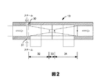
プレミキサ
プレミキサの目的は、反応器内における効果的な噴霧化のための安定な二相流を形成することである。噴霧化ノズルへと通じている、スチームと重質油原料とを混合して導管内に分散した「泡状」の流れ(又はフロー)を発生させるスロットル本体プレミキサ部の好適な構成の詳細を、図2により効果的に示す。プレミキサ13は、スチーム入口ポート30、31を有する。スチーム入口ポート30、31は、収束部32の起端に配置された入口ライン23、24からスチームを入れる。収束部32は、スロート33へと、次いで、発散部34へと通じている。スチームは、収束スロート部のすぐ先のポートを通じて、油の圧力よりも高い圧力で導入される。プレミキサを通る通路の入口直径と出口直径はほぼ同じである。
Premixer The purpose of the premixer is to form a stable two-phase flow for effective atomization in the reactor. Details of the preferred configuration of the throttle body premixer section that leads to the atomizing nozzle and produces a "bubble" flow (or flow) that mixes the steam and heavy oil feed and is dispersed in the conduit, This is shown more effectively in FIG. The
スチームポートは、スチームが液体原料と混合される高速のスチームジェットを発生させ、スチーム/油の混合物は最大剪断力でプレミキサのスロートに入り、分散した泡状の流れを形成する。ポートの数は保守要件及びアセンブリの寸法(又はサイズもしくは大きさ)に応じて異なってもよく、通常、2つから6つが適切であり、ほとんどの場合においては、2つから4つである。2つのポートが良好な結果をもたらすことが判明しており、また、これらポートは、汚損の可能性を低減するほど十分に大きく作製することができる。2つのポートは直径の方向に対向する、4つのポートは四半分にあるなどの、対称な径方向のポート配置が好ましい。スチームポートは、ポートからの対向するスチームジェットの、互いに対する衝撃による原料の混合及び噴霧化を促進するために、対で対向することが好ましい。対向していないポートからのスチームの衝突によるプレミキサ壁の侵食も低減される。良好な混合、圧力脈動の低減による安定な泡の流れ、及びスロート部自体の侵食の低減のためには、スロート領域のちょうど進入部におけるガスと液体の混合が最適であると考えられる。スチームラインに、必要であれば、示されるように、クリーニングロッドを受け入れてスロットル本体の収束部の上流側部分まで通すフランジなしのクリーニングポートを設けてもよい。 The steam port generates a high-speed steam jet where the steam is mixed with the liquid feed, and the steam / oil mixture enters the throat of the premixer with maximum shear to form a dispersed foamy flow. The number of ports may vary depending on maintenance requirements and the dimensions (or size or size) of the assembly, usually 2 to 6 is appropriate, and in most cases 2 to 4. Two ports have been found to give good results, and these ports can be made large enough to reduce the possibility of fouling. A symmetric radial port arrangement is preferred, such that the two ports are diametrically opposed and the four ports are in quadrants. The steam ports are preferably opposed in pairs to facilitate mixing and atomization of the raw materials by impact of opposing steam jets from the ports against each other. Premixer wall erosion due to steam impingement from non-opposing ports is also reduced. For good mixing, stable bubble flow with reduced pressure pulsation, and reduced erosion of the throat itself, gas and liquid mixing at the very entrance of the throat area is considered optimal. If necessary, the steam line may be provided with a flangeless cleaning port for receiving the cleaning rod and passing it to the upstream portion of the converging portion of the throttle body, as shown.
プレミキサの重要な性能基準は、スロート進入部の収束角、スロート直径及び長さ、スロートからの発散角、進入部及び出口部直径である。これらの値は原料特性(主に粘性)及び必要とされる流量に応じて経験的に最良に設定される。典型的には、浅い収束/発散角が好ましく、通常、約3〜15°(円錐の半角)であり、4〜8°の値が好ましいが、より高い流量では、不安定性指数により示される性能の差異は消失する傾向があるため、より大きな値の半角、例えば20°は許容可能である。好ましくは、収束領域と発散領域との間に円筒状の中心領域を有する対称な収束/発散領域を付与するために、収束角と発散角は、通常、実質的に同一である。 The important performance criteria of the premixer are the convergence angle, throat diameter and length of the throat entry, the divergence angle from the throat, the entry and exit diameters. These values are best set empirically depending on the raw material characteristics (mainly viscosity) and the required flow rate. Typically, shallow convergence / divergence angles are preferred, usually about 3-15 ° (conical half-angle), and values of 4-8 ° are preferred, but at higher flow rates, the performance indicated by the instability index Because the difference tends to disappear, a larger half-width, for example 20 °, is acceptable. Preferably, the convergence angle and the divergence angle are typically substantially the same in order to provide a symmetrical convergence / divergence region having a cylindrical central region between the convergence region and the divergence region.
性能9270kg/hrのプレミキサの典型的な概算寸法は、以下、表1に示す通りである(寸法はすべてmm。)。 Typical approximate dimensions of a premixer with a performance of 9270 kg / hr are shown below in Table 1 (all dimensions are mm).

オリジナルのスロート(米国特許出願公開第2012/0063961号明細書と同様の)と本改良済みスロートの最高侵食速度を、混合を定量化するために用いる、ミキサの下流側の液体体積フラクションの標準偏差とともに、表2に示す。 Standard deviation of the liquid volume fraction downstream of the mixer, where the maximum erosion rate of the original throat (similar to US 2012/0063961) and this improved throat is used to quantify mixing In addition, it is shown in Table 2.
プレミキサのスロート領域を作製するためにステライトなどの異なる物質も使用できる。あるいは、スロート領域は、侵食を低減するために、熱間等方加圧法によって作製することができる。 Different materials such as stellite can also be used to create the throat region of the premixer. Alternatively, the throat region can be made by hot isostatic pressing to reduce erosion.
例えば約7mmの小さなガスポートによって、より広範な液体流量にわたって流れの安定性が比較的より一定に維持されるが、この場合も、差異は液体流量が高くなるほど消失する傾向があるため、そのファウリングに対する耐性を高めるためには、ポートを大きくすることが好ましい。加えて、より大きなガスポートを使用すると、スチームの速度が低下し、侵食が最小限になる。流れの安定性はスロート直径が小さくなるほど付与されるが、圧力損失は直径が大きくなるほど小さくなる。しかし、ここでは、スロートの大きさは、ノズルアセンブリの所望の流量に応じて選択しなければならない。 For example, a small gas port of about 7 mm keeps the flow stability relatively more constant over a wider range of liquid flow rates, but again, the difference tends to disappear with higher liquid flow rates, so the fau In order to increase the resistance to the ring, it is preferable to increase the port. In addition, using larger gas ports reduces steam velocity and minimizes erosion. Flow stability is imparted as the throat diameter decreases, but pressure loss decreases as the diameter increases. Here, however, the throat size must be selected according to the desired flow rate of the nozzle assembly.
スロットル本体プレミキサの非常に好ましい特徴の1つは、スロットル本体プレミキサにより、流れの安定性を広範な流量にわたり維持することによって、プレミキサとノズルとの間により長い流れ導管を使用することが容易になることである。二方向流れ調整器(Bilateral Flow Conditioner)は、短い流れ導管(長さ約80cm以下)を備えるスロットル本体プレミキサと同程度の性能を提供するものの、例えば130cm以上のより長い導管内における、ガス/液体比率約1.8重量パーセント超の流れは、コールドフロー試験において急激に不安定になる傾向にある。 One highly preferred feature of the throttle body premixer is that the throttle body premixer facilitates the use of a longer flow conduit between the premixer and the nozzle by maintaining flow stability over a wide range of flow rates. That is. The Bidirectional Flow Conditioner provides the same performance as a throttle body premixer with a short flow conduit (less than about 80 cm in length), but gas / liquid, for example, in longer conduits greater than 130 cm Flows with a ratio greater than about 1.8 weight percent tend to become rapidly unstable in the cold flow test.
プレミキサは必然的に、良好な噴霧化のための付随するスチーム流とともに、所望の流量の重質油に適応するように設計される必要がある。一般に、スチーム/油の比率は、油の0.3〜1.2重量%の範囲であり、通常はむしろこれより低く、スチーム/油0.4〜0.9の範囲内であり、約0.86の比率が典型的であると思われる。スチームの供給ヘッダの圧力は、典型的には、1500〜2000kPag(約200〜290psig)の範囲内である。 The premixer necessarily needs to be designed to accommodate the desired flow rate of heavy oil, with an accompanying steam flow for good atomization. In general, the steam / oil ratio is in the range of 0.3-1.2% by weight of the oil, usually rather lower, in the range of steam / oil 0.4-0.9, about 0 A ratio of .86 appears to be typical. The steam feed header pressure is typically in the range of 1500-2000 kPag (about 200-290 psig).
流れ調整器(又はフローコンディショナ)
プレミキサの使用により形成された、分散し、安定した泡状の流れを、広範なノズル動作条件において維持することで、特定のノズルアセンブリの動作の柔軟性が高まる。ノズルまで通じている導管において、液体は連続相であり、気(スチーム)泡が液体中に存在する。ノズル出口部において、転相が発生してガスが連続相になり、その結果、液体の小滴がガス中に分散する。プレミキサ及び流れ調整器内の剪断(シヤ(shear))により、気泡の大きさの低減が生じる。分散した泡状の流れが完全にノズルオリフィスへと運ばれない場合、ノズルは、固体の流動床に液体原料のスラグを送る傾向がある。ノズルアセンブリは、図1に示すように、プレミキサと吐出ノズルとの間の、一定の断面を有する単純な管状の流れ導管によって良好に機能するが、流れ導管内の流れ安定器又は調整器によって、プレミキサ13の下流側の導管15内の乱流を更に安定させてもよく、また、吐出ノズルの前において分散した泡状の流れを維持してもよい。その最も単純な形態において、流れ調整器は、導管内に、断面が低減された流れ領域を有する部分を含み、この領域は、吐出ノズルの上流側において混合物の加速した流れを生成する。したがって、その最も単純な形態において、流れ調整器は、プレミキサと吐出ノズルとの間の導管内に配置されたカラーを含む。カラーは、単純な矩形の断面を有しても、角度を成した面を各側に有してもよい。いずれの場合においても、流れ調整器は、流れ導管の吐出端部への流れの安定性を向上するために、好ましくは、プレミキサと吐出ノズルとの間のその長さの第2の半分以内、つまり、プレミキサよりも吐出ノズルのより近傍に配置されることが好ましい。流れ調整器をプレミキサの近傍に配置すると、実質的にすべてのガス流量において、単純な流れ導管と比して限られた安定性の向上しかもたらさない。プレミキサと吐出ノズルとの間の流れ導管に沿う約50パーセント位置が著しい向上をもたらす一方で、いくつかの導管直径、例えば、吐出ノズルの2〜10個、好ましくは、2〜5個の管の直径内の位置は吐出ノズルにおける最適な流れの安定性をもたらす。
Flow regulator (or flow conditioner)
Maintaining the dispersed, stable foamy flow created by the use of the premixer over a wide range of nozzle operating conditions increases the flexibility of operation of a particular nozzle assembly. In the conduit leading to the nozzle, the liquid is a continuous phase and steam bubbles are present in the liquid. At the nozzle outlet, phase inversion occurs and the gas becomes a continuous phase, with the result that liquid droplets are dispersed in the gas. Shearing (shear) within the premixer and flow regulator results in a reduction in bubble size. If the dispersed foamy stream is not completely conveyed to the nozzle orifice, the nozzle tends to send slag of liquid feed to the solid fluidized bed. The nozzle assembly works well with a simple tubular flow conduit having a constant cross section between the premixer and the discharge nozzle, as shown in FIG. 1, but with a flow stabilizer or regulator in the flow conduit, Turbulence in the
流れ調整器の1つの好ましい形態を図3に示す。この図では、調整器35は、プレミキサの狭窄部に類似する、漸進的な収束領域に続いて漸進的な発散領域を提供する環状狭窄部を含む。この流れ調整器の形態は、機械加工され、例えば、溶接又はねじ式で取り付けることにより導管に接続され得る。流れ調整器35は、円錐の部分を規定する収束進入領域36と、同じく円錐の部分を規定する発散吐出部37と、を有し、中間円筒状スロート部39を有する。流れは、矢印によって示される方向に発生する。
One preferred form of flow regulator is shown in FIG. In this figure, the
流れ調整器の別の構成を図4に示す。図3の調整器と同様に、この部分は、適切な剪断力(ノズル本体における圧力損失により)を生成し、細かく均一な原料の小滴を形成する一方で、ノズルから吐出された噴流中の小滴を固体の床に十分に運ぶのに十分な運動量も提供するように設計されている。流れ調整器40は、一方の端から他方の端まで延びる軸流通路41を有し、上流側端部に、導管15の端部に接続するための適切なコネクタを有する。コネクタは、例えば、溶接部であっても、ねじ状のブッシュであってもよい。その他端には、流れ調整器が溶接される、ねじ式で取り付けられる、又はそうでなければ、吐出ノズル29の本体に取り付けられる。流れ導管内の中心通路は、順に、スロート43に向かって狭くなる収束領域42、これに続く発散拡散領域44、これに続く吐出ノズル29の本体内の第2の収束領域45、更にこれに続く、ノズルオリフィス自体46を含む。この場合、流れ調整器は、図3の流れ調整器に比して大幅に長くなり、拡散領域45におけるより漸進的な発散がもたらされる。この流れ調整器の形態は、単純なノズル(ディスパーサーなし)を用いて動作する場合であっても、噴霧を、200ミクロン未満の平均小滴径の微細な液体の小滴で提供することが判明しており、床へのより良好な浸透をもたらすものの、フローディスパーサーによって、床における油/コークス粒子の接触は向上する可能性がある。
Another configuration of the flow regulator is shown in FIG. Similar to the regulator of FIG. 3, this part generates an appropriate shear force (due to pressure loss in the nozzle body), forming fine and uniform droplets of raw material, while in the jet discharged from the nozzle. It is designed to provide sufficient momentum to carry the droplets sufficiently to the solid floor. The
流れ調整器部分に通じている、プレミキサの下流側のノズル本体内の円形導管15の直径及び長さもまた、分散した泡状の流れ、ゆえに、ノズルの噴霧化性能の安定性に影響を及ぼす。導管内における過度に長い滞留時間は泡の凝集及び二相流の不安定性につながる。したがって、導管内の流体滞留時間を最小限に維持する必要性と、ノズルの全体的な圧力要件に対する導管内の圧力損失の寄与との間で、導管の直径/長さの比率の選択のバランスがある。
The diameter and length of the
流れ安定器又は調整器の環状狭窄部−拡張部は、スロットル本体プレミキサの好適な形態と同様の手法で便利に作製してもよい。このスロットル本体プレミキサの好適な形態は、等しい進入角及び吐出角を有するか、あるいは、長い、継続的に拡張する発散−拡張領域に続き、狭窄部のスロートを有する。この長い発散領域は、吐出ノズルの収束部分が開始する箇所まで延在しても、そこに到達せずに終了してもよい。プレミキサとノズルとを接続する流路内の収束/発散流れ調整器と、ノズル本体内の収束流通路とを組み合わせることは、混合物中の液体油小滴に剪断力(シヤ(shear))を与え、吐出ノズルを出る際にその大きさを低減するのに非常に効果的である。 The annular constriction-expansion portion of the flow stabilizer or regulator may be conveniently made in a manner similar to the preferred form of the throttle body premixer. This preferred form of throttle body premixer has equal entry and discharge angles, or has a long, continuously expanding divergence-expansion region followed by a narrowed throat. This long divergence region may extend to a point where the convergence portion of the discharge nozzle starts or may end without reaching there. Combining the converging / diverging flow conditioner in the flow path connecting the premixer and the nozzle with the converging flow path in the nozzle body provides shear forces (shear) to the liquid oil droplets in the mixture. It is very effective in reducing the size when exiting the discharge nozzle.
いずれの形態の流れ調整器においても、第1の収束領域の目的は、プレミキサからのスチーム/油の混合物を加速し、伸張及び剪断応力によって泡の大きさを低減することである。これに続く、拡張する直径を有する発散又は拡散部は、混合物が減速することを可能にする。このため、ノズル内の次の収束部において、泡の大きさを更に低減するための、及び好ましくは、泡の大きさが、混合物が吐出口に入る更に一層前に伸張及び剪断応力によって低減され、スチーム中に分配される比較的微細な油小滴の噴流の形態で現れるように、混合物を第1の収縮部を超える加速で加速するための十分な加速が実現され得る。 In either form of flow regulator, the purpose of the first convergence region is to accelerate the steam / oil mixture from the premixer and reduce the bubble size by stretching and shear stress. The subsequent divergence or diffusion with an expanding diameter allows the mixture to slow down. For this reason, in the next converging part in the nozzle, to further reduce the foam size, and preferably the foam size is reduced by extension and shear stress even further before the mixture enters the outlet. Sufficient acceleration can be achieved to accelerate the mixture at an acceleration beyond the first contraction, so as to appear in the form of a jet of relatively fine oil droplets distributed in the steam.
ノズルアセンブリは、以下の考察に従い設計されることが好ましい。
流れ調整器の上流側の収束領域は、混合物を加速させて、後に続く、収束領域の下流側の発散領域内での流れの広がりにより、比較的小さな泡の流れを発生させるべきである。オリフィス直前の、ノズル本体内の流路の端部に配置された第2の収束領域は、混合を、第1の収束領域により実施される混合よりも加速すべきである。約2倍の加速をもたらす領域が適切であり、かつ好適である。
第1の収束領域及び拡散領域によって生成される微細な泡の寸法(又はサイズもしくは大きさ)が更に低減される場合、比較的増加した伸張及び剪断応力にそれらを曝す必要がある。この目的のため、拡散領域では流路の直径を、第2の収束領域における所望の加速が達成され得るほど十分に増加すべきである。しかしながら、この収束領域の長さは、泡の過度の再結合を避けるように制限される必要がある。3°の収束がちょうど良いことが判明している一方で、この領域における6°の収束(全角度)はあまり有用でない。第2の収束領域における収束の角度は、したがって、通常、2〜6°、好ましくは3〜5°の範囲内である。
The nozzle assembly is preferably designed according to the following considerations.
The converging region upstream of the flow regulator should accelerate the mixture and generate a relatively small bubble flow due to the subsequent flow spread in the diverging region downstream of the converging region. A second convergence region located at the end of the flow path in the nozzle body, immediately before the orifice, should accelerate the mixing more than the mixing performed by the first convergence region. A region that provides about twice the acceleration is appropriate and preferred.
If the size (or size or size) of the fine bubbles produced by the first convergence region and diffusion region is further reduced, they need to be exposed to relatively increased elongation and shear stress. For this purpose, in the diffusion region, the diameter of the channel should be increased sufficiently so that the desired acceleration in the second convergence region can be achieved. However, the length of this convergence region needs to be limited to avoid excessive recombination of bubbles. While a 3 ° convergence has been found to be just right, a 6 ° convergence (full angle) in this region is less useful. The angle of convergence in the second convergence region is therefore usually in the range 2-6 °, preferably 3-5 °.
ディスパーサー
上に示したように、単純な円筒状ノズル(すなわち、収束進入部に続いて円錐形の出口を備える)を好適なプレミキサとともに使用してもよいが、ノズルオリフィスにディスパーサーを用いることで、油と固体との接触の向上が可能になる。ディスパーサーの目的は、液体を中心線から引き出して、液体の固体との接触を最大にすることである。これにより、コークス粒子をより薄い膜でより均一かつ平均的に原料でコーティングすることが可能になる。より薄い膜では拡散路が短くなるため、二次的な分解が減少する傾向にあり、その結果、液体の収率が向上する。したがって、収率の更なる向上は、主として、ノズルにディスパーサーを用いることから得られる。初期の試験でいくつかの種類のディスパーサーを評価した。これらには、「手裏剣型」、複数穴型、複数ローブ型、例えば、クローバ及びファン型の設計が含まれる。パタネータを用いた流束測定に基づくと、「手裏剣型」及び複数穴型の設計は、重質油小滴を液体コアから引き離すのに効果的でないことが判明した。平坦2ローブ形又はファン形の噴流噴霧パターンをもたらすクローバパターン及び2ローブパターン又はファンパターンは、噴流の流動床との相互作用において同程度の性能を有していた。好ましい複数ローブ型クローバ構成は、噴流/床相互作用試験に基づくものであり、この試験では、面積に対する外周部の比率がより高く、固体の同伴が高められたディスパーサーが、全般的により良好な性能を示した。パタネータは、ノズルからの噴霧のパターンを試験するために作製された機器である。この機器は、機械的パタネーションの代わりに用いられ、その高い速度及び高い分解能により、噴霧の均一性及びパターンが重要な種々の用途に使用することが可能である。この技術は、West Lafayette,INに所在のEn’Urga Inc.により開発されたものである。この機器は、米国特許第6184989号に包含されることがEn’Urgaによって示されている。
As shown on the disperser, a simple cylindrical nozzle (i.e., subsequently an outlet of conical convergence entrance portion) may be used with a suitable premixer, but the use of a disperser in the nozzle orifice Thus, the contact between the oil and the solid can be improved. The purpose of the disperser is to draw the liquid from the centerline and maximize the contact of the liquid with the solid. This makes it possible to coat the coke particles with the raw material more uniformly and on average with a thinner film. Thinner membranes have a shorter diffusion path and tend to reduce secondary degradation, resulting in improved liquid yield. Therefore, further improvement in yield is obtained primarily from the use of a disperser in the nozzle. Several types of dispersers were evaluated in early trials. These include “shuriken”, multi-hole, multi-lobe designs such as clover and fan designs. Based on flux measurements using a pattern generator, the “shuriken” and multi-hole designs were found to be ineffective at pulling heavy oil droplets away from the liquid core. The clover pattern and the two-lobe pattern or fan pattern, resulting in a flat two-lobe or fan-shaped jet spray pattern, had comparable performance in interacting the jet with the fluidized bed. Preferred multiple lobed crowbar configuration is based on the jet / floor Interaction Test In this test, the higher the ratio of the outer peripheral portion to the area, solid disperser entrained is increased of generally better Showed performance. A patternator is an instrument made to test the spray pattern from a nozzle. This instrument is used in place of mechanical patterning, and due to its high speed and high resolution, it can be used in a variety of applications where spray uniformity and pattern are important. This technology is available from En'Urga Inc., located in West Lafayette, IN. It was developed by. This instrument has been shown by En'Urga to be included in US Pat. No. 6,184,8989.
クローバ型ディスパーサーの特定の実施形態を図5A及び図5Bに示す。ディスパーサー50は、ノズル本体の収束部分の端部にある入口51から、断面が継続的に増加する出口オリフィス52まで流路を有する。これにより、スチームが、狭窄したノズル通路を出る際に圧力が低下するにつれて広がり、その際、油/スチームの混合物が、ディスパーサーの幾何学的形状によって決定される拡張パターンへと分散することが可能になる。複数ローブ型ディスパーサーは、本体に機械加工した4つのローブ53を有し、各ローブの壁は、中空円錐部の一部分を規定する。いくつかの中空円錐部の軸線はディスパーサーの中心軸線と対称に交差し、ディスパーサーの増加する断面積を提供して、スチームが広がり、油の噴流を微細な噴霧へと分割することを可能にする。複数ローブ型ディスパーサーのローブの数は、原料特性及び利用可能な物理的空間に従い選択してもよく、一般に、2つから6つのローブが好適であり、ほとんどの場合においては、4つが最適な数である。2ローブ型設計は端面から見ると、ファンに類似するものの狭いウエスト領域を有するパターンとなる数字の8に類似し、噴流における強固な中心コアの形成の排除を補助し、3ローブ型設計は3つ葉のクローバ等に類似する。使用においては、4つ葉のクローバが、「+」よりもむしろ「x」の配向で、つまり、「+」の垂直/水平配向とは対照的に、水平位に対し45°/135°のローブを有して使用される場合に、より良好な油/コークスの接触をもたらすことが判明している。
本明細書の開示内容は、以下の態様を含み得る。
(態様1)
循環流動床反応器であって、垂直軸線の周りに円形断面を有する反応器壁と、流動化ガス用の下方入口と、前記下方流動化ガス入口の上方及び前記反応器壁の周りにある液体重質油原料及び噴霧化スチーム用の原料注入ノズルアセンブリとを有し、
前記ノズルアセンブリがそれぞれ、前記反応器壁を貫通して前記反応器内へと延び、前記反応器内に吐出口と、前記吐出口から離れた端部に前記液体重質油原料用の原料入口とを有し、各原料注入ノズルアセンブリが、
前記液体重質油原料を噴霧化スチームと組み合わせて、液体中に気泡を含む液体原料/スチームの混合物を形成するプレミキサ部であって、前記プレミキサ部が、連続する収束用領域及び発散用領域を含み、前記収束用領域の進入部に配置される複数の径方向スチーム入口ポートを有する、プレミキサ部と、
前記プレミキサ部の出口に続いて接続され、前記プレミキサ部から吐出ノズルまで延び、前記プレミキサによって形成される前記液体/スチームの混合物の流れを前記吐出ノズルへと移送する、流れ導管部と、
前記流れ導管部に続いて接続される収束進入部を有する吐出ノズルであって、前記液体原料/スチームの混合物を剪断し、前記吐出ノズルから出る際に、低減された寸法の液体原料小滴を形成する、吐出ノズルと、
を含む、
循環流動床反応器。
(態様2)
前記プレミキサ部が、前記収束用領域と前記発散用領域とを接続する中心円筒状スロート部を含む、態様1に記載の循環流動床反応器。
(態様3)
前記ノズルアセンブリが、流れ導管部を有し、前記流れ導管部が、前記プレミキサからの前記液体原料/スチームの混合物中の前記気泡の寸法を低減するための、連続する収束領域及び発散領域を含む、態様1に記載の循環流動床反応器。
(態様4)
前記ノズルアセンブリが、拡散領域によって分離されるタンデム型収束領域を含む流れ導管部を有する、態様1に記載の循環流動床反応器。
(態様5)
前記吐出ノズルの出口に、円筒状噴流に比して増加した表面積を有する、円筒状噴流と同様に形成される液体噴流プルームを発生させるためのマルチローブディスパーサー(multilobe disperser)を含む、態様1に記載の循環流動床反応器。
(態様6)
前記ディスパーサー(disperser)が、円形断面を有する中心流路を含む本体と、前記本体内の複数のローブとを有し、各ローブの壁は中空円錐部の一部分を規定し、前記中空円錐部の軸線は前記ディスパーサーの中心軸線と対称に交差し、前記ディスパーサー本体内に、増加する断面積を有する、増大するマルチローブ出口通路を規定する、態様3に記載の循環流動床反応器。
(態様7)
流動コーキング反応器であって、垂直軸線の周りに円形断面を有する反応器壁と、流動化ガス用の下方入口と、前記下方流動化ガス入口の上方及び前記反応器壁の周りにある液体重質油原料及び噴霧化スチーム用の原料注入ノズルアセンブリとを有し、
前記ノズルアセンブリがそれぞれ、前記反応器壁を貫通して当該反応器内へと延び、前記反応器内に吐出ノズルオリフィスと、前記吐出ノズルオリフィスから離れた端部に前記液体重質油原料用の入口とを有し、各原料注入ノズルアセンブリが、
前記液体重質油原料を噴霧化スチームと組み合わせて、液体中に気泡を含む液体原料/スチームの混合物を形成するプレミキサ部であって、前記プレミキサ部が、連続する収束用領域及び発散用領域と、前記収束用領域と前記発散用領域とを接続する中心スロート部とを含み、前記収束用領域の進入部に配置される複数の径方向スチーム入口ポートを有する、プレミキサ部と、
前記プレミキサ部の出口に続いて接続され、前記プレミキサ部から吐出ノズルまで延び、前記プレミキサによって形成される前記液体/スチームの混合物の流れを前記吐出ノズルへと移送する、流れ導管部と、
前記流れ導管部に続いて接続される収束進入部を有する吐出ノズルであって、前記液体原料/スチームの混合物を剪断し、前記吐出ノズルから出る際に、低減された寸法の液体原料小滴を形成する、吐出ノズルと、
を含む、
流動コーキング反応器。
(態様8)
前記プレミキサ部が、前記収束用領域と前記発散用領域とを接続する中心円筒状スロート部を含む、態様6に記載の流動コーキング反応器。
(態様9)
前記ノズル本体が、流れ導管部を有し、前記流れ導管部が、前記プレミキサからの前記液体原料/スチームの混合物中の前記気泡の寸法を低減するための、連続する収束領域及び発散領域を含む、態様6に記載の流動コーキング反応器。
(態様10)
前記ノズルアセンブリが、拡散領域によって分離されるタンデム型収束領域を含む流れ導管部を有する、態様6に記載の流動コーキング反応器。
(態様11)
前記原料注入ノズルがそれぞれ、前記吐出ノズルの出口に、円筒状噴流に比して増加した表面積を有する、円筒状噴流と同様に形成される液体噴流プルームを発生させるためのマルチローブディスパーサーを含む、態様6に記載の流動コーキング反応器。
(態様12)
前記ディスパーサーが、円形断面を有する中心流路を含む本体と、前記本体内の複数のローブとを有し、各ローブの壁は中空円錐部の一部分を規定し、前記中空円錐部の軸線は前記ディスパーサーの中心軸線と対称に交差し、前記ディスパーサー本体内に、増加する断面積を有する、増大するマルチローブ出口通路を規定する、態様8に記載の流動コーキング反応器。
(態様13)
流動床コーキング反応器を有する流動コーキングユニットであって、
垂直軸線の周りに円形断面を有していて反応器壁によって囲まれている(又は閉じ込められている(confined))反応部と、
高密度床反応部の下方にある基部領域であって、前記基部領域において、前記高密度床反応部内で、細かく分割された固体コークス粒子の高密度床を流動化するために流動化ガスが注入される、基部領域と、
前記反応器壁の前記周縁部に前記基部領域の上方で複数の高さに配置される複数の重質油入口と、
前記反応部の上方にあり、前記高密度床反応部から分離されるスクラバ部と、
前記高密度床反応部の頂部にある少なくとも1つのサイクロンであって、各サイクロンが、前記反応部を出るガス及びコークス粒子のための入口と、前記スクラバ部へと吐出するサイクロンガス出口と、前記サイクロン内でガスから分離されるコークス粒子を前記高密度床反応部へと戻すためのサイクロンディプレグとを有する、少なくとも1つのサイクロンと、
前記反応器の前記基部領域にあるストリッピング部と、
原料注入ノズルアセンブリと
を含み、
前記原料注入ノズルアセンブリがそれぞれ、前記反応器壁を貫通して前記反応器内へと延び、前記反応器内に吐出口と、前記吐出ノズルから離れた端部に液体重質油原料用の入口とを有し、各原料注入ノズルアセンブリが、
前記液体重質油原料を噴霧化スチームと組み合わせて、液体中に気泡を含む液体原料/スチームの混合物を形成するプレミキサ部であって、前記プレミキサ部が、連続する収束用領域及び発散用領域を含み、前記収束用領域の進入部に配置される複数の径方向スチーム入口ポートを有する、プレミキサ部と、
前記プレミキサ部の出口に続いて接続され、前記プレミキサ部から吐出ノズルまで延び、前記プレミキサによって形成される前記液体/スチームの混合物の流れを前記吐出ノズルへと移送する、流れ導管部と、
前記流れ導管部に続いて接続される収束進入部を有する吐出ノズルであって、前記液体原料/スチームの混合物を剪断し、前記吐出ノズルから出る際に、低減された寸法の液体原料小滴を形成する、吐出ノズルと、
を含む、
流動コーキングユニット。
(態様14)
前記プレミキサ部が、前記収束用領域と前記発散用領域とを接続する中心円筒状スロート部を含む、態様13に記載の流動コーキングユニット。
(態様15)
前記ノズル本体が、流れ導管部を有し、前記流れ導管部が、前記液体原料/スチームの混合物中の前記気泡の寸法を低減するための、連続する収束領域及び発散領域を含む、態様13に記載の流動コーキングユニット。
(態様16)
前記ノズルアセンブリが、拡散領域によって分離されるタンデム型収束領域を含む流れ導管部を有する、態様13に記載の流動コーキングユニット。
(態様17)
各原料注入ノズルアセンブリが、前記吐出ノズルの出口に、円筒状噴流に比して増加した表面積を有する、円筒状噴流と同様に形成される液体噴流プルームを発生させるためのディスパーサーを含み、前記ディスパーサーが、円形断面を有する中心流路を含む本体と、前記本体内の複数のローブとを有し、各ローブの壁は中空円錐部の一部分を規定し、前記中空円錐部の軸線は前記ディスパーサーの中心軸線と対称に交差し、前記ディスパーサー本体内に、増加する断面積を有する、増大するマルチローブ出口通路を規定する、態様13に記載の流動コーキングユニット。
(態様18)
前記ディスパーサーが、4つのローブを含む本体を有し、各ローブの壁は中空円錐部の一部分を規定し、前記中空円錐部の軸線は前記ディスパーサーの中心軸線と対称に交差し、前記ディスパーサー本体内に、増加する断面積を有する、増大する4ローブの出口通路を規定する、態様17に記載の流動コーキングユニット。
(態様19)
前記反応器が、前記ユニット内において、コークスラインによってバーナ/ヒータに結合されており、前記コークスラインは、コークスを前記ストリッパの底部から前記バーナ/ヒータに移送するための低温コークス移送ラインと、高温コークスを前記バーナ/ヒータから前記反応器に戻すための高温コークス戻りラインとを含む、態様13に記載の流動コーキングユニット。
(態様20)
コークス移送ラインによって前記ヒータ/バーナに接続されたコークスガス化器部を含む、態様17に記載の流動コーキングユニット。
While particular embodiments of the cloverleaf disperser shown in FIGS. 5A and 5B. The
The disclosure of the present specification may include the following aspects.
(Aspect 1)
A circulating fluidized bed reactor comprising a reactor wall having a circular cross-section around a vertical axis, a lower inlet for fluidizing gas, and a liquid above and around the lower fluidizing gas inlet A heavy oil feedstock and a feedstock injection nozzle assembly for atomizing steam;
Each of the nozzle assemblies extends through the reactor wall into the reactor, a discharge port in the reactor, and a feed inlet for the liquid heavy oil feed at an end remote from the discharge port And each raw material injection nozzle assembly has
A premixer unit that combines the liquid heavy oil raw material with atomized steam to form a liquid raw material / steam mixture containing bubbles in the liquid, wherein the premixer unit has a continuous convergence region and a diverging region. Including a premixer section having a plurality of radial steam inlet ports disposed in the entry section of the convergence region;
A flow conduit portion connected subsequent to the outlet of the premixer portion, extending from the premixer portion to a discharge nozzle and transferring a flow of the liquid / steam mixture formed by the premixer to the discharge nozzle;
A discharge nozzle having a converging entry connected subsequent to the flow conduit section, wherein the liquid feed / steam mixture is sheared to produce reduced size liquid feed droplets upon exiting the discharge nozzle. Forming a discharge nozzle;
including,
Circulating fluidized bed reactor.
(Aspect 2)
The circulating fluidized bed reactor according to aspect 1, wherein the premixer section includes a central cylindrical throat section that connects the convergence area and the diverging area.
(Aspect 3)
The nozzle assembly has a flow conduit portion, the flow conduit portion including a continuous converging region and a diverging region to reduce the size of the bubbles in the liquid feed / steam mixture from the premixer. A circulating fluidized bed reactor according to embodiment 1.
(Aspect 4)
The circulating fluidized bed reactor according to aspect 1, wherein the nozzle assembly has a flow conduit portion comprising a tandem converging region separated by a diffusion region.
(Aspect 5)
Aspect 1 including a multilobe disperser at the outlet of the discharge nozzle for generating a liquid jet plume formed in the same manner as a cylindrical jet having a surface area increased compared to the cylindrical jet The circulating fluidized bed reactor described in 1.
(Aspect 6)
The disperser has a body including a central flow path having a circular cross section, and a plurality of lobes in the body, each lobe wall defining a portion of a hollow cone, the hollow cone The circulating fluidized bed reactor according to embodiment 3, wherein the axis of the crossing symmetrically intersects the central axis of the disperser and defines an increasing multi-lobe outlet passage in the disperser body having an increasing cross-sectional area.
(Aspect 7)
A flow coking reactor comprising a reactor wall having a circular cross-section around a vertical axis, a lower inlet for fluidizing gas, a liquid weight above and around the lower fluidizing gas inlet A raw material injection nozzle assembly for the refined oil raw material and atomizing steam,
Each of the nozzle assemblies extends through the reactor wall into the reactor, a discharge nozzle orifice in the reactor, and an end for the liquid heavy oil feedstock at an end remote from the discharge nozzle orifice. Each raw material injection nozzle assembly has an inlet,
A premixer unit that combines the liquid heavy oil raw material with atomized steam to form a liquid raw material / steam mixture containing bubbles in the liquid, the premixer unit comprising a continuous convergence region and a diverging region; A pre-mixer section including a central throat section connecting the convergence area and the divergence area, and having a plurality of radial steam inlet ports arranged at an entry section of the convergence area;
A flow conduit portion connected subsequent to the outlet of the premixer portion, extending from the premixer portion to a discharge nozzle and transferring a flow of the liquid / steam mixture formed by the premixer to the discharge nozzle;
A discharge nozzle having a converging entry connected subsequent to the flow conduit section, wherein the liquid feed / steam mixture is sheared to produce reduced size liquid feed droplets upon exiting the discharge nozzle. Forming a discharge nozzle;
including,
Fluid coking reactor.
(Aspect 8)
The flow coking reactor according to aspect 6, wherein the premixer section includes a central cylindrical throat section that connects the converging area and the diverging area.
(Aspect 9)
The nozzle body has a flow conduit portion, the flow conduit portion including a continuous converging region and a diverging region for reducing the size of the bubbles in the liquid feed / steam mixture from the premixer. A fluid coking reactor according to embodiment 6.
(Aspect 10)
The flow coking reactor according to aspect 6, wherein the nozzle assembly has a flow conduit portion comprising a tandem focusing region separated by a diffusion region.
(Aspect 11)
Each of the raw material injection nozzles includes a multi-lobe disperser for generating a liquid jet plume formed in the same manner as a cylindrical jet, having an increased surface area compared to the cylindrical jet at the outlet of the discharge nozzle A fluid coking reactor according to embodiment 6.
(Aspect 12)
The disperser has a body including a central flow path having a circular cross section, and a plurality of lobes in the body, the walls of each lobe defining a portion of the hollow cone, the axis of the hollow cone being 9. A flow coking reactor according to aspect 8, wherein the flow coking reactor defines an increasing multilobe outlet passage that intersects symmetrically with the central axis of the disperser and has an increasing cross-sectional area within the disperser body.
(Aspect 13)
A fluid coking unit having a fluidized bed coking reactor,
A reaction section having a circular cross section around a vertical axis and surrounded (or confined) by a reactor wall;
A base region below the high-density bed reaction section, in which fluidized gas is injected to fluidize the high-density bed of finely divided solid coke particles in the high-density bed reaction section. A base region;
A plurality of heavy oil inlets disposed at a plurality of heights above the base region at the peripheral edge of the reactor wall;
A scrubber section above the reaction section and separated from the high density bed reaction section;
At least one cyclone at the top of the dense bed reaction section, each cyclone having an inlet for gas and coke particles exiting the reaction section, a cyclone gas outlet for discharging to the scrubber section, and At least one cyclone having a cyclone prepreg for returning coke particles separated from the gas in the cyclone to the dense bed reactor;
A stripping section in the base region of the reactor;
Raw material injection nozzle assembly and
Including
Each of the feed injection nozzle assemblies extends through the reactor wall into the reactor, a discharge port in the reactor, and an inlet for a liquid heavy oil feed at the end remote from the discharge nozzle And each raw material injection nozzle assembly has
A premixer unit that combines the liquid heavy oil raw material with atomized steam to form a liquid raw material / steam mixture containing bubbles in the liquid, wherein the premixer unit has a continuous convergence region and a diverging region. Including a premixer section having a plurality of radial steam inlet ports disposed in the entry section of the convergence region;
A flow conduit portion connected subsequent to the outlet of the premixer portion, extending from the premixer portion to a discharge nozzle and transferring a flow of the liquid / steam mixture formed by the premixer to the discharge nozzle;
A discharge nozzle having a converging entry connected subsequent to the flow conduit section, wherein the liquid feed / steam mixture is sheared to produce reduced size liquid feed droplets upon exiting the discharge nozzle. Forming a discharge nozzle;
including,
Fluid coking unit.
(Aspect 14)
The flow coking unit according to
(Aspect 15)
In
(Aspect 16)
14. A flow coking unit according to
(Aspect 17)
Each raw material injection nozzle assembly includes a disperser at the outlet of the discharge nozzle for generating a liquid jet plume formed in the same manner as a cylindrical jet having a surface area increased compared to the cylindrical jet, The disperser has a body including a central flow path having a circular cross section, and a plurality of lobes in the body, each lobe wall defining a portion of a hollow cone, the axis of the hollow cone being the
(Aspect 18)
The disperser has a body including four lobes, the walls of each lobe defining a portion of a hollow cone, the axis of the hollow cone intersecting symmetrically with the central axis of the disperser, and the
(Aspect 19)
The reactor is coupled to a burner / heater within the unit by a coke line, the coke line being connected to a low temperature coke transfer line for transferring coke from the bottom of the stripper to the burner / heater, and a high temperature A fluid coking unit according to
(Aspect 20)
18. A fluid coking unit according to
Claims (20)
前記ノズルアセンブリがそれぞれ、前記反応器壁を貫通して前記反応器内へと延び、前記反応器内に吐出口と、前記吐出口から離れた端部に前記液体重質油原料用の原料入口とを有し、各原料注入ノズルアセンブリが、
前記液体重質油原料を噴霧化スチームと組み合わせて、液体中に気泡を含む液体原料/スチームの混合物を形成するプレミキサ部であって、前記プレミキサ部が、連続する収束用領域及び発散用領域を含み、前記収束用領域の進入部に配置される複数の径方向スチーム入口ポートを有する、プレミキサ部と、
前記プレミキサ部の出口に続いて接続され、前記プレミキサ部から吐出ノズルまで延び、前記プレミキサによって形成される前記液体/スチームの混合物の流れを前記吐出ノズルへと移送する、流れ導管部と、
前記流れ導管部に続いて接続される収束進入部を有する吐出ノズルであって、前記液体原料/スチームの混合物を剪断し、前記吐出ノズルから出る際に、低減された寸法の液体原料小滴を形成する、吐出ノズルと、
を含む、
循環流動床反応器。 A circulating fluidized bed reactor comprising a reactor wall having a circular cross-section around a vertical axis, a lower inlet for fluidizing gas, and a liquid above and around the lower fluidizing gas inlet A heavy oil feedstock and a feedstock injection nozzle assembly for atomizing steam;
Each of the nozzle assemblies extends through the reactor wall into the reactor, a discharge port in the reactor, and a feed inlet for the liquid heavy oil feed at an end remote from the discharge port And each raw material injection nozzle assembly has
A premixer unit that combines the liquid heavy oil raw material with atomized steam to form a liquid raw material / steam mixture containing bubbles in the liquid, wherein the premixer unit has a continuous convergence region and a diverging region. Including a premixer section having a plurality of radial steam inlet ports disposed in the entry section of the convergence region;
A flow conduit portion connected subsequent to the outlet of the premixer portion, extending from the premixer portion to a discharge nozzle and transferring a flow of the liquid / steam mixture formed by the premixer to the discharge nozzle;
A discharge nozzle having a converging entry connected subsequent to the flow conduit section, wherein the liquid feed / steam mixture is sheared to produce reduced size liquid feed droplets upon exiting the discharge nozzle. Forming a discharge nozzle;
including,
Circulating fluidized bed reactor.
前記ノズルアセンブリがそれぞれ、前記反応器壁を貫通して当該反応器内へと延び、前記反応器内に吐出ノズルオリフィスと、前記吐出ノズルオリフィスから離れた端部に前記液体重質油原料用の入口とを有し、各原料注入ノズルアセンブリが、
前記液体重質油原料を噴霧化スチームと組み合わせて、液体中に気泡を含む液体原料/スチームの混合物を形成するプレミキサ部であって、前記プレミキサ部が、連続する収束用領域及び発散用領域と、前記収束用領域と前記発散用領域とを接続する中心スロート部とを含み、前記収束用領域の進入部に配置される複数の径方向スチーム入口ポートを有する、プレミキサ部と、
前記プレミキサ部の出口に続いて接続され、前記プレミキサ部から吐出ノズルまで延び、前記プレミキサによって形成される前記液体/スチームの混合物の流れを前記吐出ノズルへと移送する、流れ導管部と、
前記流れ導管部に続いて接続される収束進入部を有する吐出ノズルであって、前記液体原料/スチームの混合物を剪断し、前記吐出ノズルから出る際に、低減された寸法の液体原料小滴を形成する、吐出ノズルと、
を含む、
流動コーキング反応器。 A flow coking reactor comprising a reactor wall having a circular cross-section around a vertical axis, a lower inlet for fluidizing gas, a liquid weight above and around the lower fluidizing gas inlet A raw material injection nozzle assembly for the refined oil raw material and atomizing steam,
Each of the nozzle assemblies extends through the reactor wall into the reactor, a discharge nozzle orifice in the reactor, and an end for the liquid heavy oil feedstock at an end remote from the discharge nozzle orifice . Each raw material injection nozzle assembly has an inlet,
A premixer unit that combines the liquid heavy oil raw material with atomized steam to form a liquid raw material / steam mixture containing bubbles in the liquid, the premixer unit comprising a continuous convergence region and a diverging region; A pre-mixer section including a central throat section connecting the convergence area and the divergence area, and having a plurality of radial steam inlet ports arranged at an entry section of the convergence area;
A flow conduit portion connected subsequent to the outlet of the premixer portion, extending from the premixer portion to a discharge nozzle and transferring a flow of the liquid / steam mixture formed by the premixer to the discharge nozzle;
A discharge nozzle having a converging entry connected subsequent to the flow conduit section, wherein the liquid feed / steam mixture is sheared to produce reduced size liquid feed droplets upon exiting the discharge nozzle. Forming a discharge nozzle;
including,
Fluid coking reactor.
垂直軸線の周りに円形断面を有していて反応器壁によって囲まれている反応部と、
高密度床反応部の下方にある基部領域であって、前記基部領域において、前記高密度床反応部内で、細かく分割された固体コークス粒子の高密度床を流動化するために流動化ガスが注入される、基部領域と、
前記反応器壁の前記周縁部に前記基部領域の上方で複数の高さに配置される複数の重質油入口と、
前記反応部の上方にあり、前記高密度床反応部から分離されるスクラバ部と、
前記高密度床反応部の頂部にある少なくとも1つのサイクロンであって、各サイクロンが、前記反応部を出るガス及びコークス粒子のための入口と、前記スクラバ部へと吐出するサイクロンガス出口と、前記サイクロン内でガスから分離されるコークス粒子を前記高密度床反応部へと戻すためのサイクロンディプレグとを有する、少なくとも1つのサイクロンと、
前記反応器の前記基部領域にあるストリッピング部と、
原料注入ノズルアセンブリと
を含み、
前記原料注入ノズルアセンブリがそれぞれ、前記反応器壁を貫通して前記反応器内へと延び、前記反応器内に吐出口と、前記吐出ノズルから離れた端部に液体重質油原料用の入口とを有し、各原料注入ノズルアセンブリが、
前記液体重質油原料を噴霧化スチームと組み合わせて、液体中に気泡を含む液体原料/スチームの混合物を形成するプレミキサ部であって、前記プレミキサ部が、連続する収束用領域及び発散用領域を含み、前記収束用領域の進入部に配置される複数の径方向スチーム入口ポートを有する、プレミキサ部と、
前記プレミキサ部の出口に続いて接続され、前記プレミキサ部から吐出ノズルまで延び、前記プレミキサによって形成される前記液体/スチームの混合物の流れを前記吐出ノズルへと移送する、流れ導管部と、
前記流れ導管部に続いて接続される収束進入部を有する吐出ノズルであって、前記液体原料/スチームの混合物を剪断し、前記吐出ノズルから出る際に、低減された寸法の液体原料小滴を形成する、吐出ノズルと、
を含む、
流動コーキングユニット。 A fluid coking unit having a fluidized bed coking reactor,
A reaction section having a circular cross section around a vertical axis and surrounded by a reactor wall;
A base region below the high-density bed reaction section, in which fluidized gas is injected to fluidize the high-density bed of finely divided solid coke particles in the high-density bed reaction section. A base region;
A plurality of heavy oil inlets disposed at a plurality of heights above the base region at the peripheral edge of the reactor wall;
A scrubber section above the reaction section and separated from the high density bed reaction section;
At least one cyclone at the top of the dense bed reaction section, each cyclone having an inlet for gas and coke particles exiting the reaction section, a cyclone gas outlet for discharging to the scrubber section, and At least one cyclone having a cyclone prepreg for returning coke particles separated from the gas in the cyclone to the dense bed reactor;
A stripping section in the base region of the reactor;
A raw material injection nozzle assembly,
Each of the feed injection nozzle assemblies extends through the reactor wall into the reactor, a discharge port in the reactor, and an inlet for a liquid heavy oil feed at the end remote from the discharge nozzle And each raw material injection nozzle assembly has
A premixer unit that combines the liquid heavy oil raw material with atomized steam to form a liquid raw material / steam mixture containing bubbles in the liquid, wherein the premixer unit has a continuous convergence region and a diverging region. Including a premixer section having a plurality of radial steam inlet ports disposed in the entry section of the convergence region;
A flow conduit portion connected subsequent to the outlet of the premixer portion, extending from the premixer portion to a discharge nozzle and transferring a flow of the liquid / steam mixture formed by the premixer to the discharge nozzle;
A discharge nozzle having a converging entry connected subsequent to the flow conduit section, wherein the liquid feed / steam mixture is sheared to produce reduced size liquid feed droplets upon exiting the discharge nozzle. Forming a discharge nozzle;
including,
Fluid coking unit.
Applications Claiming Priority (3)
| Application Number | Priority Date | Filing Date | Title |
|---|---|---|---|
| US201462042911P | 2014-08-28 | 2014-08-28 | |
| US62/042,911 | 2014-08-28 | ||
| PCT/US2015/042662 WO2016032671A1 (en) | 2014-08-28 | 2015-07-29 | Fluid injection nozzle for fluid bed reactors |
Publications (3)
| Publication Number | Publication Date |
|---|---|
| JP2017534436A JP2017534436A (en) | 2017-11-24 |
| JP2017534436A5 JP2017534436A5 (en) | 2019-08-22 |
| JP6570621B2 true JP6570621B2 (en) | 2019-09-04 |
Family
ID=53938391
Family Applications (1)
| Application Number | Title | Priority Date | Filing Date |
|---|---|---|---|
| JP2017511628A Expired - Fee Related JP6570621B2 (en) | 2014-08-28 | 2015-07-29 | Fluid injection nozzle for fluidized bed reactor |
Country Status (9)
| Country | Link |
|---|---|
| US (1) | US9738836B2 (en) |
| EP (1) | EP3185998A1 (en) |
| JP (1) | JP6570621B2 (en) |
| CN (1) | CN106573216B (en) |
| MX (1) | MX2016015751A (en) |
| PE (1) | PE20170394A1 (en) |
| RU (1) | RU2680484C2 (en) |
| SG (1) | SG11201609801VA (en) |
| WO (1) | WO2016032671A1 (en) |
Families Citing this family (10)
| Publication number | Priority date | Publication date | Assignee | Title |
|---|---|---|---|---|
| CN109382046B (en) * | 2017-08-11 | 2021-03-09 | 中国石油天然气股份有限公司 | Fixed fluidized bed reactor feeding system |
| CN109419513B (en) * | 2017-08-28 | 2020-12-08 | 大连圣迈新材料有限公司 | Automatic powder supply trace detection equipment for extracting fingerprints by powder method on crime scene and powder supply method thereof |
| FR3077511B1 (en) * | 2018-02-08 | 2022-07-22 | Total Raffinage Chimie | CHARGE INJECTION DEVICE OF AN FCC UNIT. |
| CN111111564B (en) * | 2018-10-30 | 2022-07-12 | 中国石油化工股份有限公司 | Reaction device and reaction method for producing aromatic nitrile through ammoxidation |
| CN110003935B (en) * | 2019-04-16 | 2021-03-30 | 枣庄杰富意振兴化工有限公司 | Coal tar pretreatment equipment |
| US20220274850A1 (en) * | 2019-08-16 | 2022-09-01 | Cambi Technology As | Device For Controlling Thermal Hydrolysis Decompression and Process Plant Comprising Such Device |
| KR102524372B1 (en) | 2019-09-24 | 2023-04-21 | 주식회사 엘지화학 | Soket type fluid distributing device |
| CN111903846B (en) * | 2020-07-31 | 2023-10-31 | 浙江新和成股份有限公司 | Stable carotenoid microcapsule with high bioavailability and preparation method thereof |
| CN116478731A (en) * | 2023-05-06 | 2023-07-25 | 中国地质调查局油气资源调查中心 | Reaction method for solar-driven coal gasification |
| CN116849914B (en) * | 2023-07-13 | 2024-05-17 | 中国科学院深圳先进技术研究院 | Reusable Laplace valve and glaucoma drainage device |
Family Cites Families (16)
| Publication number | Priority date | Publication date | Assignee | Title |
|---|---|---|---|---|
| US2546570A (en) | 1948-11-15 | 1951-03-27 | Phillips Petroleum Co | Fluidizied bed reactor |
| US3443757A (en) | 1966-10-14 | 1969-05-13 | Aviat Uk | Supersonic fluid flow exhaust nozzles |
| DE3525161A1 (en) | 1985-03-05 | 1986-09-11 | DFVLR-Deutsche Forschungs- und Versuchsanstalt für Luft- und Raumfahrt e.V., 5000 Köln | METHOD AND DEVICE FOR LOW-WEAR SPRAYING OF LIQUID, HIGH-VISCOSITY AND / OR SUSPENSIVE FUELS FOR COMBUSTION OR GASIFICATION IN BURNER FLAMES |
| US4875810A (en) * | 1985-10-21 | 1989-10-24 | Canon Kabushiki Kaisha | Apparatus for controlling fine particle flow |
| WO1987005043A1 (en) * | 1986-02-19 | 1987-08-27 | Gaetano Russo | Hydrocarbon cracking apparatus |
| EP0318185A1 (en) * | 1987-11-23 | 1989-05-31 | Conoco Inc. | FCC feed nozzle design |
| US5306418A (en) | 1991-12-13 | 1994-04-26 | Mobil Oil Corporation | Heavy hydrocarbon feed atomization |
| US5289976A (en) | 1991-12-13 | 1994-03-01 | Mobil Oil Corporation | Heavy hydrocarbon feed atomization |
| CA2224615C (en) | 1997-12-11 | 2001-07-31 | Terence E. Base | Nozzle for atomizing liquid in two phase flow |
| US6003789A (en) | 1997-12-15 | 1999-12-21 | Aec Oil Sands, L.P. | Nozzle for atomizing liquid in two phase flow |
| US6387247B1 (en) * | 1999-09-03 | 2002-05-14 | Shell Oil Company | Feed injection system for catalytic cracking process |
| CA2404798C (en) | 2002-09-24 | 2007-02-20 | Edward W. Chan | Nozzle/mixer assembly |
| CA2462397C (en) | 2003-03-24 | 2010-05-04 | Thomas William Mccracken | Mixing arrangement for atomizing nozzle in multi-phase flow |
| DE102005019444B4 (en) * | 2005-04-21 | 2008-02-28 | Glatt Gmbh | Spray nozzle for a fluidized bed device |
| US8999246B2 (en) | 2010-05-25 | 2015-04-07 | Exxonmobil Research And Engineering Company | Fluid injection nozzle for fluid bed reactors |
| US20130048539A1 (en) * | 2011-08-23 | 2013-02-28 | Marathon Oil Canada Corporation | Methods and Systems for Upgrading Hydrocarbon |
-
2015
- 2015-07-29 SG SG11201609801VA patent/SG11201609801VA/en unknown
- 2015-07-29 JP JP2017511628A patent/JP6570621B2/en not_active Expired - Fee Related
- 2015-07-29 RU RU2017107525A patent/RU2680484C2/en active
- 2015-07-29 EP EP15753797.8A patent/EP3185998A1/en not_active Withdrawn
- 2015-07-29 CN CN201580040109.0A patent/CN106573216B/en active Active
- 2015-07-29 PE PE2017000270A patent/PE20170394A1/en unknown
- 2015-07-29 US US14/812,363 patent/US9738836B2/en active Active
- 2015-07-29 MX MX2016015751A patent/MX2016015751A/en unknown
- 2015-07-29 WO PCT/US2015/042662 patent/WO2016032671A1/en active Application Filing
Also Published As
| Publication number | Publication date |
|---|---|
| EP3185998A1 (en) | 2017-07-05 |
| SG11201609801VA (en) | 2016-12-29 |
| US9738836B2 (en) | 2017-08-22 |
| RU2680484C2 (en) | 2019-02-21 |
| RU2017107525A3 (en) | 2019-01-30 |
| PE20170394A1 (en) | 2017-04-26 |
| US20160060541A1 (en) | 2016-03-03 |
| RU2017107525A (en) | 2018-10-01 |
| MX2016015751A (en) | 2017-02-27 |
| WO2016032671A1 (en) | 2016-03-03 |
| CN106573216B (en) | 2020-10-30 |
| CN106573216A (en) | 2017-04-19 |
| JP2017534436A (en) | 2017-11-24 |
Similar Documents
| Publication | Publication Date | Title |
|---|---|---|
| JP6570621B2 (en) | Fluid injection nozzle for fluidized bed reactor | |
| US8999246B2 (en) | Fluid injection nozzle for fluid bed reactors | |
| JP2017534436A5 (en) | ||
| JP4486296B2 (en) | Feed material dispersion system and fluid catalytic cracking method for fluid catalytic cracker | |
| US5139748A (en) | FCC riser with transverse feed injection | |
| US4793913A (en) | Method for liquid feed dispersion in fluid catalytic cracking systems | |
| EP3286285B1 (en) | Fluid coking process | |
| US5562818A (en) | FCC feed injection with non-quiescent mixing | |
| US5358632A (en) | FCC feed injection with non-quiescent mixing | |
| US9889420B2 (en) | Fluid injection nozzle for fluid bed reactors | |
| US5061457A (en) | Apparatus for liquid feed dispersion in fluid catalytic cracking systems | |
| CN114630708B (en) | Fluid catalytic cracking feed injector | |
| CA3025862C (en) | Fluid coking using high thrust feed nozzles | |
| NO175192B (en) |
Legal Events
| Date | Code | Title | Description |
|---|---|---|---|
| A621 | Written request for application examination |
Free format text: JAPANESE INTERMEDIATE CODE: A621 Effective date: 20180619 |
|
| A977 | Report on retrieval |
Free format text: JAPANESE INTERMEDIATE CODE: A971007 Effective date: 20190306 |
|
| A131 | Notification of reasons for refusal |
Free format text: JAPANESE INTERMEDIATE CODE: A131 Effective date: 20190312 |
|
| A524 | Written submission of copy of amendment under article 19 pct |
Free format text: JAPANESE INTERMEDIATE CODE: A524 Effective date: 20190611 |
|
| TRDD | Decision of grant or rejection written | ||
| A01 | Written decision to grant a patent or to grant a registration (utility model) |
Free format text: JAPANESE INTERMEDIATE CODE: A01 Effective date: 20190730 |
|
| A61 | First payment of annual fees (during grant procedure) |
Free format text: JAPANESE INTERMEDIATE CODE: A61 Effective date: 20190806 |
|
| R150 | Certificate of patent or registration of utility model |
Ref document number: 6570621 Country of ref document: JP Free format text: JAPANESE INTERMEDIATE CODE: R150 |
|
| LAPS | Cancellation because of no payment of annual fees |