JP6569361B2 - Interactive projector and method for correcting Z coordinate thereof - Google Patents
Interactive projector and method for correcting Z coordinate thereof Download PDFInfo
- Publication number
- JP6569361B2 JP6569361B2 JP2015151578A JP2015151578A JP6569361B2 JP 6569361 B2 JP6569361 B2 JP 6569361B2 JP 2015151578 A JP2015151578 A JP 2015151578A JP 2015151578 A JP2015151578 A JP 2015151578A JP 6569361 B2 JP6569361 B2 JP 6569361B2
- Authority
- JP
- Japan
- Prior art keywords
- indicator
- coordinate value
- coordinate
- screen surface
- correction
- Prior art date
- Legal status (The legal status is an assumption and is not a legal conclusion. Google has not performed a legal analysis and makes no representation as to the accuracy of the status listed.)
- Active
Links
Images


Classifications
-
- G—PHYSICS
- G06—COMPUTING; CALCULATING OR COUNTING
- G06F—ELECTRIC DIGITAL DATA PROCESSING
- G06F3/00—Input arrangements for transferring data to be processed into a form capable of being handled by the computer; Output arrangements for transferring data from processing unit to output unit, e.g. interface arrangements
- G06F3/01—Input arrangements or combined input and output arrangements for interaction between user and computer
- G06F3/03—Arrangements for converting the position or the displacement of a member into a coded form
- G06F3/0304—Detection arrangements using opto-electronic means
- G06F3/0325—Detection arrangements using opto-electronic means using a plurality of light emitters or reflectors or a plurality of detectors forming a reference frame from which to derive the orientation of the object, e.g. by triangulation or on the basis of reference deformation in the picked up image
-
- H—ELECTRICITY
- H04—ELECTRIC COMMUNICATION TECHNIQUE
- H04N—PICTORIAL COMMUNICATION, e.g. TELEVISION
- H04N23/00—Cameras or camera modules comprising electronic image sensors; Control thereof
- H04N23/10—Cameras or camera modules comprising electronic image sensors; Control thereof for generating image signals from different wavelengths
- H04N23/13—Cameras or camera modules comprising electronic image sensors; Control thereof for generating image signals from different wavelengths with multiple sensors
- H04N23/15—Image signal generation with circuitry for avoiding or correcting image misregistration
-
- H—ELECTRICITY
- H04—ELECTRIC COMMUNICATION TECHNIQUE
- H04N—PICTORIAL COMMUNICATION, e.g. TELEVISION
- H04N23/00—Cameras or camera modules comprising electronic image sensors; Control thereof
- H04N23/56—Cameras or camera modules comprising electronic image sensors; Control thereof provided with illuminating means
-
- H—ELECTRICITY
- H04—ELECTRIC COMMUNICATION TECHNIQUE
- H04N—PICTORIAL COMMUNICATION, e.g. TELEVISION
- H04N23/00—Cameras or camera modules comprising electronic image sensors; Control thereof
- H04N23/90—Arrangement of cameras or camera modules, e.g. multiple cameras in TV studios or sports stadiums
-
- H—ELECTRICITY
- H04—ELECTRIC COMMUNICATION TECHNIQUE
- H04N—PICTORIAL COMMUNICATION, e.g. TELEVISION
- H04N9/00—Details of colour television systems
- H04N9/12—Picture reproducers
- H04N9/31—Projection devices for colour picture display, e.g. using electronic spatial light modulators [ESLM]
- H04N9/3179—Video signal processing therefor
-
- H—ELECTRICITY
- H04—ELECTRIC COMMUNICATION TECHNIQUE
- H04N—PICTORIAL COMMUNICATION, e.g. TELEVISION
- H04N9/00—Details of colour television systems
- H04N9/12—Picture reproducers
- H04N9/31—Projection devices for colour picture display, e.g. using electronic spatial light modulators [ESLM]
- H04N9/3191—Testing thereof
- H04N9/3194—Testing thereof including sensor feedback
Landscapes
- Engineering & Computer Science (AREA)
- Multimedia (AREA)
- Signal Processing (AREA)
- General Engineering & Computer Science (AREA)
- Theoretical Computer Science (AREA)
- Physics & Mathematics (AREA)
- Human Computer Interaction (AREA)
- General Physics & Mathematics (AREA)
- Projection Apparatus (AREA)
- Position Input By Displaying (AREA)
- Geometry (AREA)
Description
本発明は、ユーザーの指示体による指示を受け取ることが可能なインタラクティブプロジェクターに関する。 The present invention relates to an interactive projector capable of receiving an instruction from a user's indicator.
特許文献1には、投写画面をスクリーンに投写するとともに、指などの対象物(object)を含む画像をカメラで撮像し、この撮像画像を用いて対象物の位置を検出することが可能な投写型表示装置(プロジェクター)が開示されている。指などの対象物は、投写画面に対して指示を行うための指示体として利用される。すなわち、プロジェクターは、対象物の先端がスクリーンに接しているときに投写画面に対して描画等の所定の指示が入力されているものと認識し、その指示に応じて投写画面を再描画する。従って、ユーザーは、投写画面をユーザーインターフェースとして用いて、各種の指示を入力することが可能である。このように、スクリーン上の投写画面を入力可能ユーザーインターフェースとして利用できるタイプのプロジェクターを、「インタラクティブプロジェクター」と呼ぶ。また、投写画面に対して指示を行うために利用される対象物を「指示体(pointing element)」と呼ぶ。 In Patent Document 1, a projection screen is projected onto a screen, an image including an object such as a finger is captured by a camera, and the position of the object can be detected using the captured image. A type display device (projector) is disclosed. An object such as a finger is used as an indicator for giving an instruction to the projection screen. That is, the projector recognizes that a predetermined instruction such as drawing is input to the projection screen when the tip of the object is in contact with the screen, and redraws the projection screen according to the instruction. Therefore, the user can input various instructions using the projection screen as a user interface. A projector that can use a projection screen on the screen as an inputable user interface is called an “interactive projector”. An object used for giving an instruction to the projection screen is called a “pointing element”.
典型的なインタラクティブプロジェクターでは、指示体が投写画面(スクリーン面)に接触しているか否かに応じて、指示体によって指示がなされているか否かを判定する。従って、スクリーン面に対する指示体の接触検出の精度が重要である。しかしながら、従来技術では、接触検出の精度が必ずしも十分でない場合があり、その検出精度の向上が望まれていた。 In a typical interactive projector, it is determined whether or not an instruction is given by the indicator according to whether or not the indicator is in contact with the projection screen (screen surface). Therefore, the accuracy of detecting the contact of the indicator with the screen surface is important. However, in the prior art, the accuracy of contact detection may not always be sufficient, and an improvement in detection accuracy has been desired.
本発明は、上述の課題の少なくとも一部を解決するためになされたものであり、以下の形態又は適用例として実現することが可能である。
本発明の一形態によれば、指示体の位置を検出するインタラクティブプロジェクターが提供される。このインタラクティブプロジェクターは、スクリーン面に画像を投写する投写部と、前記指示体の3次元座標値を検出すると共に、前記スクリーン面から離れる方向の座標をZ座標としたとき、前記指示体のZ座標値と前記スクリーン面のZ座標値との間の差分と予め設定された差分閾値との関係に基づいて前記スクリーン面に対する前記指示体の接触の有無を検出する検出部と、前記指示体のZ座標値の履歴に基づいて、前記スクリーン面のZ座標値の補正をする補正部と、を備え、前記補正部は、前記指示体のZ座標値の履歴のデータ数が所定数より少ない間は、前記補正を行なわず、前記補正部は、前記指示体のZ座標値のヒストグラムに基づいて前記補正を行い、前記補正部は、前記指示体のXY座標値が前回から変化しているときは、前記指示体のZ座標値を前記ヒストグラムに加算する加算処理を行ない、前記指示体のXY座標値が前回から変化していないときには、前記加算処理を行なわず、前記補正を行なわない。
この形態のインタラクティブプロジェクターによれば、指示体のXY座標値が前回から変化していないときには、ヒストグラムへの加算処理を行なわず、スクリーン面のZ座標値の補正を行なわないので、特殊な事情が発生している場合における座標データがヒストグラムに反映されることを抑制でき、接触検出の検出精度が低下することを抑制できる。
その他、本発明は、以下のような形態又は適用例として実現することも可能である。
SUMMARY An advantage of some aspects of the invention is to solve at least a part of the problems described above, and the invention can be implemented as the following forms or application examples.
According to an aspect of the present invention, an interactive projector that detects the position of an indicator is provided. The interactive projector detects a three-dimensional coordinate value of the projection unit that projects an image on a screen surface and the indicator, and uses the Z coordinate of the indicator as a coordinate in a direction away from the screen surface. A detection unit that detects presence or absence of contact of the indicator with the screen surface based on a relationship between a difference between the value and a Z coordinate value of the screen surface and a preset difference threshold value; and Z of the indicator A correction unit that corrects the Z-coordinate value of the screen surface based on a history of coordinate values, and the correction unit while the number of data of the Z-coordinate value history of the indicator is less than a predetermined number. , without the correction, the correction unit performs the correction based on the histogram of Z-coordinate values of the pointer, the correction unit, when the XY coordinates of the pointer is changed from the previous Performs an addition process for adding the Z-coordinate value of the pointer in the histogram, when the XY coordinates of the pointer is not changed from the last time, without the addition processing is not performed the correction.
According to the interactive projector of this aspect, when the XY coordinate value of the indicator has not changed from the previous time, the addition to the histogram is not performed, and the Z coordinate value of the screen surface is not corrected. It can suppress that the coordinate data in the case where it generate | occur | produces is reflected in a histogram, and can suppress that the detection accuracy of contact detection falls.
In addition, the present invention can be realized as the following forms or application examples.
(1)本発明の一形態によれば、指示体の位置を検出するインタラクティブプロジェクターが提供される。このインタラクティブプロジェクターは、スクリーン面に画像を投写する投写部と;前記指示体の3次元座標値を検出すると共に、前記スクリーン面から離れる方向の座標をZ座標としたとき、前記指示体のZ座標値と前記スクリーン面のZ座標値との間の差分と予め設定された差分閾値との関係に基づいて前記スクリーン面に対する前記指示体の接触の有無を検出する検出部と;前記指示体のZ座標値の履歴に基づいて、前記スクリーン面のZ座標値と、前記指示体のZ座標値と、前記差分閾値と、のうちの少なくとも一つを補正する補正部と;を備える。
このインタラクティブプロジェクターによれば、指示体のZ座標値の履歴に基づいて、スクリーン面のZ座標値と、指示体のZ座標値と、差分閾値と、のうちの少なくとも一つを補正するので、指示体のZ座標値とスクリーン面のZ座標値のいずれかにズレが発生している場合にも、そのズレを補正することができ、スクリーン面に対する指示体の接触の有無を精度良く検出することが可能となる。
(1) According to one aspect of the present invention, an interactive projector that detects the position of an indicator is provided. The interactive projector includes: a projection unit that projects an image on a screen surface; and a three-dimensional coordinate value of the indicator, and a Z coordinate of the indicator when a coordinate in a direction away from the screen surface is a Z coordinate. A detecting unit for detecting presence or absence of contact of the indicator with the screen surface based on a relationship between a difference between the value and a Z coordinate value of the screen surface and a preset difference threshold; A correction unit that corrects at least one of the Z coordinate value of the screen surface, the Z coordinate value of the indicator, and the difference threshold value based on a history of coordinate values.
According to this interactive projector, since at least one of the Z coordinate value of the screen surface, the Z coordinate value of the indicator, and the difference threshold value is corrected based on the history of the Z coordinate value of the indicator, Even when there is a deviation in either the Z coordinate value of the indicator or the Z coordinate value of the screen surface, the deviation can be corrected and the presence or absence of contact of the indicator with the screen surface can be detected with high accuracy. It becomes possible.
(2)上記インタラクティブプロジェクターにおいて、前記スクリーン面のうちで前記画像が投写される投写範囲を撮像する複数台のカメラをさらに備え、前記検出部は、前記複数台のカメラによって撮像された前記指示体を含む複数の画像を用いた三角測量により前記指示体の3次元座標値を検出するものとしてもよい。
この構成によれば、三角測量によって指示体の3次元座標値を精度良く検出できる。
(2) The interactive projector may further include a plurality of cameras that capture a projection range in which the image is projected on the screen surface, and the detection unit is the indicator captured by the plurality of cameras. The three-dimensional coordinate value of the indicator may be detected by triangulation using a plurality of images including.
According to this configuration, the three-dimensional coordinate value of the indicator can be detected with high accuracy by triangulation.
(3)上記インタラクティブプロジェクターにおいて、前記補正部は、前記指示体のZ座標値のヒストグラムに基づいて前記補正を行うものとしてもよい。
指示体のZ座標値のヒストグラムには、指示体がスクリーン面に接触している状態が反映されているので、そのヒストグラムに基づいて補正を行うようにすれば、スクリーン面に対する指示体の接触の有無の検出精度を向上できる。
(3) In the interactive projector, the correction unit may perform the correction based on a histogram of Z coordinate values of the indicator.
Since the histogram of the Z coordinate value of the indicator reflects the state in which the indicator is in contact with the screen surface, if correction is performed based on the histogram, the contact of the indicator with respect to the screen surface The presence / absence detection accuracy can be improved.
(4)上記インタラクティブプロジェクターにおいて、前記補正部は、前記指示体のZ座標値のヒストグラムのピークを示すZ座標値と、前記スクリーン面のZ座標値との大小関係に応じて前記補正を行うものとしてもよい。
ヒストグラムのピークを示すZ座標値とスクリーン面のZ座標値との大小関係はZ座標のズレを示しているので、この大小関係に応じて補正を行うようにすれば、スクリーン面に対する指示体の接触の有無の検出精度を向上できる。
(4) In the above interactive projector, the correction unit performs the correction according to the magnitude relationship between the Z coordinate value indicating a peak of the histogram of Z-coordinate values of the pointer, and Z-coordinate values of the screen surface It is good.
Since the magnitude relationship between the Z coordinate value indicating the peak of the histogram and the Z coordinate value of the screen surface indicates a deviation of the Z coordinate, if correction is performed in accordance with this magnitude relationship, the indicator on the screen surface is corrected. The detection accuracy of the presence or absence of contact can be improved.
(5)上記インタラクティブプロジェクターにおいて、前記補正部は、前記指示体のZ座標値の履歴における最小Z座標値と、前記スクリーン面のZ座標値との大小関係に応じて前記補正を行うものとしてもよい。
指示体のZ座標値の履歴における最小Z座標値とスクリーン面のZ座標値との大小関係は、Z座標のズレを示しているので、この大小関係に応じて補正を行うようにすれば、スクリーン面に対する指示体の接触の有無の検出精度を向上できる。
(5) In the above interactive projector, the correction unit includes a minimum Z coordinate value in the history of the Z coordinate value of the pointer, even to perform the correction in accordance with the magnitude relationship between the Z coordinate values of the screen surface Good.
The magnitude relationship between the Z coordinate value of the minimum Z coordinate values and the screen surface in the history of the Z coordinate value of the pointer, it indicates a deviation of Z coordinates, when to perform the correction according to the magnitude relation, The detection accuracy of the presence or absence of contact of the indicator with the screen surface can be improved.
(6)上記インタラクティブプロジェクターにおいて、前記補正部は、前記指示体のZ方向速度がゼロであるときの前記指示体のZ座標値の履歴に基づいて前記補正を行うとしてもよい。
指示体のZ方向速度がゼロであるときは、指示体がスクリーン面に接触しているものと考えることができる。従って、指示体のZ方向速度がゼロであるときの指示体のZ座標値の履歴に基づいて補正を行うようにすれば、スクリーン面に対する指示体の接触の有無の検出精度を向上できる。
(6) In the interactive projector, the correction unit may perform the correction based on a history of Z coordinate values of the indicator when the Z-direction speed of the indicator is zero.
When the Z-direction speed of the indicator is zero, it can be considered that the indicator is in contact with the screen surface. Therefore, if correction is performed based on the history of the Z coordinate value of the indicator when the Z-direction speed of the indicator is zero, the detection accuracy of the presence or absence of the indicator touching the screen surface can be improved.
本発明は、種々の形態で実現することが可能であり、例えば、スクリーン及び指示体のうちの一方又は両方とインタラクティブプロジェクターとを含むシステム、インタラクティブプロジェクターの制御方法又は制御装置、それらの方法または装置の機能を実現するためのコンピュータプログラム、そのコンピュータプログラムを記録した一時的でない記録媒体(non-transitory storage medium)等の様々な形態で実現することができる。 The present invention can be realized in various forms, for example, a system including one or both of a screen and a pointer and an interactive projector, a control method or control apparatus for an interactive projector, and a method or apparatus thereof. The present invention can be realized in various forms such as a computer program for realizing the above function and a non-transitory storage medium on which the computer program is recorded.
A.第1実施形態
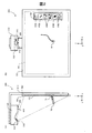
図1は、本発明の第1実施形態におけるインタラクティブプロジェクションシステム900の斜視図である。このシステム900は、インタラクティブプロジェクター100と、スクリーン板920と、自発光指示体70とを有している。スクリーン板920の前面は、投写スクリーン面SS(projection Screen Surface)として利用される。プロジェクター100は、支持部材910によってスクリーン板920の前方かつ上方に固定されている。なお、図1では投写スクリーン面SSを鉛直に配置しているが、投写スクリーン面SSを水平に配置してこのシステム900を使用することも可能である。
A. First Embodiment FIG. 1 is a perspective view of an
プロジェクター100は、投写スクリーン面SS上に投写画面PS(Projected Screen)を投写する。投写画面PSは、通常は、プロジェクター100内で描画された画像を含んでいる。プロジェクター100内で描画された画像がない場合には、プロジェクター100から投写画面PSに光が照射されて、白色画像が表示される。本明細書において、「投写スクリーン面SS」(又は「スクリーン面SS」)とは、画像が投写される部材の表面を意味する。また、「投写画面PS」とは、プロジェクター100によって投写スクリーン面SS上に投写された画像の領域を意味する。通常は、投写スクリーン面SSの一部に投写画面PSが投写される。
The
自発光指示体70は、発光可能な先端部71と、使用者が保持する軸部72と、軸部72に設けられたボタンスイッチ73とを有するペン型の指示体である。自発光指示体70の構成や機能については後述する。このシステム900では、1つ又は複数の自発光指示体70とともに、1つ又は複数の非発光指示体80(非発光のペンや指など)を利用可能である。
The self-
図2(A)は、インタラクティブプロジェクションシステム900の側面図であり、図2(B)はその正面図である。本明細書では、投写の左右に沿った方向をX方向と定義し、スクリーン面SSの上下に沿った方向をY方向と定義し、スクリーン面SSの法線に沿った方向をZ方向と定義している。なお、便宜上、X方向を「左右方向」とも呼び、Y方向を「上下方向」とも呼び、Z方向を「前後方向」とも呼ぶ。Z方向は、スクリーン面SSから離れる方向である。また、Y方向(上下方向)のうち、プロジェクター100から見て投写画面PSが存在する方向を「下方向」と呼ぶ。なお、図2(A)では、図示の便宜上、スクリーン板920のうちの投写画面PSの範囲にハッチングを付している。
2A is a side view of the
プロジェクター100は、投写画面PSをスクリーン面SS上に投写する投写レンズ210と、投写画面PSの領域を撮像する第1カメラ310及び第2カメラ320と、指示体(自発光指示体70及び非発光指示体80)に検出光を照明するための検出光照射部410とを有している。検出光としては、例えば近赤外光が使用される。2台のカメラ310,320は、検出光の波長を含む波長領域の光を受光して撮像する第1の撮像機能を少なくとも有している。2台のカメラ310,320のうちの少なくとも一方は、更に、可視光を含む光を受光して撮像する第2の撮像機能を有し、これらの2つの撮像機能を切り替え可能に構成されていることが好ましい。例えば、2台のカメラ310,320は、可視光を遮断して近赤外光のみを通過させる近赤外フィルターをレンズの前に配置したりレンズの前から後退させたりすることが可能な近赤外フィルター切換機構(図示せず)をそれぞれ備えることが好ましい。2台のカメラ310,320の配置や向きについては更に後述する。
The
図2(B)の例は、インタラクティブプロジェクションシステム900がホワイトボードモードで動作している様子を示している。ホワイトボードモードは、自発光指示体70や非発光指示体80を用いて投写画面PS上にユーザーが任意に描画できるモードである。スクリーン面SS上には、ツールボックスTBを含む投写画面PSが投写されている。このツールボックスTBは、処理を元に戻す取消ボタンUDBと、マウスポインターを選択するポインターボタンPTBと、描画用のペンツールを選択するペンボタンPEBと、描画された画像を消去する消しゴムツールを選択する消しゴムボタンERBと、画面を次に進めたり前に戻したりする前方/後方ボタンFRBと、を含んでいる。ユーザーは、指示体を用いてこれらのボタンをクリックすることによって、そのボタンに応じた処理を行ったり、ツールを選択したりすることが可能である。なお、システム900の起動直後は、マウスポインターがデフォールトツールとして選択されるようにしてもよい。図2(B)の例では、ユーザーがペンツールを選択した後、自発光指示体70の先端部71をスクリーン面SSに接した状態で投写画面PS内で移動させることにより、投写画面PS内に線が描画されてゆく様子が描かれている。この線の描画は、プロジェクター100の内部の投写画像生成部(後述)によって行われる。
The example of FIG. 2B shows a state where the
なお、インタラクティブプロジェクションシステム900は、ホワイトボードモード以外の他のモードでも動作可能である。例えば、このシステム900は、パーソナルコンピューター(図示せず)から通信回線を介して転送されたデータの画像を投写画面PSに表示するPCインタラクティブモードでも動作可能である。PCインタラクティブモードにおいては、例えば表計算ソフトウェアなどのデータの画像が表示され、その画像内に表示された各種のツールやアイコンを利用してデータの入力、作成、修正等を行うことが可能となる。
Note that the
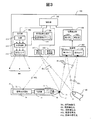
図3は、インタラクティブプロジェクター100と自発光指示体70の内部構成を示すブロック図である。プロジェクター100は、制御部700と、投写部200と、投写画像生成部500と、位置検出部600と、撮像部300と、検出光照射部410と、信号光送信部430とを有している。
FIG. 3 is a block diagram showing the internal configuration of the
制御部700は、プロジェクター100内部の各部の制御を行う。また、制御部700は、位置検出部600で検出された指示体(自発光指示体70や非発光指示体80)によって投写画面PS上で行われた指示の内容を判定するとともに、その指示の内容に従って投写画像を作成又は変更することを投写画像生成部500に指令する。
The
投写画像生成部500は、投写画像を記憶する投写画像メモリー510を有しており、投写部200によってスクリーン面SS上に投写される投写画像を生成する機能を有する。投写画像生成部500は、更に、投写画面PS(図2(B))の台形歪みを補正するキーストーン補正部としての機能を有することが好ましい。
The projection
投写部200は、投写画像生成部500で生成された投写画像をスクリーン面SS上に投写する機能を有する。投写部200は、図2で説明した投写レンズ210の他に、光変調部220と、光源230とを有する。光変調部220は、投写画像メモリー510から与えられる投写画像データに応じて光源230からの光を変調することによって投写画像光IMLを形成する。この投写画像光IMLは、典型的には、RGBの3色の可視光を含むカラー画像光であり、投写レンズ210によってスクリーン面SS上に投写される。なお、光源230としては、超高圧水銀ランプ等の光源ランプの他、発光ダイオードやレーザーダイオード等の種々の光源を採用可能である。また、光変調部220としては、透過型又は反射型の液晶パネルやデジタルミラーデバイス等を採用可能であり、色光別に複数の光変調部220を備えた構成としてもよい。
The
検出光照射部410は、指示体(自発光指示体70及び非発光指示体80)の先端部を検出するための照射検出光IDLをスクリーン面SSとその前方の空間にわたって照射する。照射検出光IDLとしては、例えば近赤外光が使用される。検出光照射部410は、カメラ310,320の撮像タイミングを含む所定の期間にのみ点灯し、他の期間では消灯する。或いは、検出光照射部410は、システム900の動作中は常に点灯状態に維持されるようにしてもよい。
The detection
信号光送信部430は、自発光指示体70によって受信される装置信号光ASLを送信する機能を有する。装置信号光ASLは、同期用の近赤外光信号であり、プロジェクター100の信号光送信部430から自発光指示体70に対して定期的に発せられる。自発光指示体70の先端発光部77は、装置信号光ASLに同期して、予め定められた発光パターン(発光シーケンス)を有する近赤外光である指示体信号光PSL(後述)を発する。また、撮像部300のカメラ310,320は、指示体(自発光指示体70及び非発光指示体80)の位置検出を行う際に、装置信号光ASLに同期した所定のタイミングで撮像を実行する。
The
撮像部300は、図2で説明した第1カメラ310と第2カメラ320とを有している。前述したように、2台のカメラ310,320は、検出光の波長を含む波長領域の光を受光して撮像する機能を有する。図3の例では、検出光照射部410によって照射された照射検出光IDLが指示体(自発光指示体70及び非発光指示体80)で反射され、その反射検出光RDLが2台のカメラ310,320によって受光されて撮像される様子が描かれている。2台のカメラ310,320は、更に、自発光指示体70の先端発光部77から発せられる近赤外光である指示体信号光PSLも受光して撮像する。2台のカメラ310,320の撮像は、検出光照射部410から発せられる照射検出光IDLがオン状態(発光状態)である第1の期間と、照射検出光IDLがオフ状態(非発光状態)である第2の期間と、の両方で実行される。位置検出部600は、これらの2種類の期間における画像を比較することによって、画像内に含まれる個々の指示体が、自発光指示体70と非発光指示体80のいずれであるかを判定することが可能である。
The
なお、2台のカメラ310,320の少なくとも一方は、近赤外光を含む光を用いて撮像する機能に加えて、可視光を含む光を用いて撮像する機能を有することが好ましい。こうすれば、スクリーン面SS上に投写された投写画面PSをそのカメラで撮像し、その画像を利用して投写画像生成部500がキーストーン補正を実行することが可能である。1台以上のカメラを利用したキーストーン補正の方法は周知なので、ここではその説明は省略する。
Note that at least one of the two
位置検出部600は、2台のカメラ310,320で撮像された画像を用い、三角測量を利用して指示体(自発光指示体70や非発光指示体80)の先端部の3次元位置を決定する機能を有する。この際、位置検出部600は、自発光指示体70の発光パターンを利用して、画像内の個々の指示体が自発光指示体70と非発光指示体80のいずれであるかについても判定する。
The
本実施形態において、位置検出部600は、検出部610と補正部620とを有している。検出部610は、2台のカメラ310,320によって撮像された指示体80(又は70)を含む画像を用いた三角測量によって指示体の3次元座標値を検出する機能と、投写画面PS(スクリーン面SS)に対する指示体の接触の有無を検出する機能とを有する。補正部620は、指示体80(又は70)のZ座標値の履歴に基づいて、スクリーン面SSのZ座標値と、三角測量により得られる指示体80(又は70)のZ座標値と、接触判定に用いる差分閾値δZth(後述する)と、のうちの少なくとも一つを補正する機能を有する。これらの機能については更に後述する。
In the present embodiment, the
自発光指示体70には、ボタンスイッチ73の他に、信号光受信部74と、制御部75と、先端スイッチ76と、先端発光部77とが設けられている。信号光受信部74は、プロジェクター100の信号光送信部430から発せられた装置信号光ASLを受信する機能を有する。先端スイッチ76は、自発光指示体70の先端部71が押されるとオン状態になり、先端部71が解放されるとオフ状態になるスイッチである。先端スイッチ76は、通常はオフ状態にあり、自発光指示体70の先端部71がスクリーン面SSに接触するとその接触圧によってオン状態になる。先端スイッチ76がオフ状態のときには、制御部75は、先端スイッチ76がオフ状態であることを示す特定の第1の発光パターンで先端発光部77を発光させることによって、第1の発光パターンを有する指示体信号光PSLを発する。一方、先端スイッチ76がオン状態になると、制御部75は、先端スイッチ76がオン状態であることを示す特定の第2の発光パターンで先端発光部77を発光させることによって、第2の発光パターンを有する指示体信号光PSLを発する。これらの第1の発光パターンと第2の発光パターンは、互いに異なるので、位置検出部600は、2台のカメラ310,320で撮像された画像を分析することによって、先端スイッチ76がオン状態かオフ状態かを識別することが可能である。
In addition to the
上述のように、本実施形態では、自発光指示体70の先端部71がスクリーン面SSに接しているか否かの接触判定を、先端スイッチ76のオン/オフに応じて行っている。ところで、自発光指示体70の先端部71の3次元位置は、2台のカメラ310,320で撮像された画像を用いた三角測量によって求めることができるので、この3次元位置を用いて自発光指示体70の先端部71の接触判定を実行することも可能である。
As described above, in the present embodiment, whether or not the
自発光指示体70のボタンスイッチ73は、先端スイッチ76と同じ機能を有する。従って、制御部75は、ユーザーによってボタンスイッチ73が押された状態では上記第2の発光パターンで先端発光部77を発光させ、ボタンスイッチ73が押されていない状態では上記第1の発光パターンで先端発光部77を発光させる。換言すれば、制御部75は、先端スイッチ76とボタンスイッチ73の少なくとも一方がオンの状態では上記第2の発光パターンで先端発光部77を発光させ、先端スイッチ76とボタンスイッチ73の両方がオフの状態では上記第1の発光パターンで先端発光部77を発光させる。
The
但し、ボタンスイッチ73に対して先端スイッチ76と異なる機能を割り当てるようにしてもよい。例えば、ボタンスイッチ73に対してマウスの右クリックボタンと同じ機能を割り当てた場合には、ユーザーがボタンスイッチ73を押すと、右クリックの指示がプロジェクター100の制御部700に伝達され、その指示に応じた処理が実行される。このように、ボタンスイッチ73に対して先端スイッチ76と異なる機能を割り当てた場合には、先端発光部77は、先端スイッチ76のオン/オフ状態及びボタンスイッチ73のオン/オフ状態に応じて、互いに異なる4つの発光パターンで発光する。この場合には、自発光指示体70は、先端スイッチ76とボタンスイッチ73のオン/オフ状態の4つの組み合わせを区別しつつ、プロジェクター100に伝達することが可能である。
However, a function different from the
図3に描かれている5種類の信号光の具体例をまとめると以下の通りである。
(1)投写画像光IML:スクリーン面SSに投写画面PSを投写するために、投写レンズ210によってスクリーン面SS上に投写される画像光(可視光)である。
(2)照射検出光IDL: 指示体(自発光指示体70及び非発光指示体80)の先端部を検出するために、検出光照射部410によってスクリーン面SSとその前方の空間にわたって照射される近赤外光である。
(3)反射検出光RDL:照射検出光IDLとして照射された近赤外光のうち、指示体(自発光指示体70及び非発光指示体80)によって反射され、2台のカメラ310,320によって受光される近赤外光である。
(4)装置信号光ASL:プロジェクター100と自発光指示体70との同期をとるために、プロジェクター100の信号光送信部430から定期的に発せられる近赤外光である。
(5)指示体信号光PSL:装置信号光ASLに同期したタイミングで、自発光指示体70の先端発光部77から発せられる近赤外光である。指示体信号光PSLの発光パターンは、自発光指示体70のスイッチ73,76のオン/オフ状態に応じて変更される。また、複数の自発光指示体70を識別する固有の発光パターンを有する。
Specific examples of the five types of signal light depicted in FIG. 3 are summarized as follows.
(1) Projected image light IML: Image light (visible light) projected onto the screen surface SS by the
(2) Irradiation detection light IDL: In order to detect the tip of the indicators (self-
(3) Reflected detection light RDL: Of the near-infrared light irradiated as the irradiation detection light IDL, it is reflected by the indicators (the self-
(4) Device signal light ASL: near-infrared light periodically emitted from the signal
(5) Indicator signal light PSL: Near-infrared light emitted from the tip
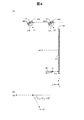
図4(A)は、2台のカメラ310,320の配置と向きを示す説明図である。この図は、各カメラ310,320のカメラ基準位置O1,O2を通るYZ平面上の配置を示している。第1カメラ310は、第2カメラ320よりもスクリーン面SSからの垂直距離(Z方向の距離)がより大きな位置に配置されている。2台のカメラ310,320のそれぞれは、カメラ基準位置O1,O2と、画像面MP1,MP2(結像面)と、光軸V1,V2と、画角2θ1,2θ2とを用いてモデル化されている。
FIG. 4A is an explanatory diagram showing the arrangement and orientation of the two
図4(A)では、非発光指示体80の先端部81が、投写画面PSから距離δZだけ離間した状態が描かれている。上述したように、非発光指示体80の先端部81の3次元位置は、2台のカメラ310,320で撮像された画像を利用した三角測量によって決定される。インタラクティブプロジェクションシステム900では、非発光指示体80の先端部81とスクリーン面SSとのZ方向の距離δZを精度良く検出することが望まれている。そこで、本実施形態では、2台のカメラ310,320の配置と向きを工夫することによって、非発光指示体80の先端部81とスクリーン面SSとの間のZ方向の距離δZの検出精度を向上させている。なお、Z方向の距離δZの検出精度を、「Z座標の解像度」とも呼ぶ。
4A shows a state in which the
図4(A)において、第2カメラ320は、第1カメラ310よりも投写画面PSからの垂直距離(Z方向の距離)がより小さな位置に配置されている。また、2台のカメラ310,320は、Y方向の位置が同じ(投写画面PSからの高さが同じ)位置に配置されている。更に、2台のカメラ310,320の光軸V1,V2は互いに平行である。
In FIG. 4A, the
図4(B)は、2台のカメラ310,320の光軸ベクトルV1,V2と投写画面法線ベクトルNVとの関係を示している。光軸ベクトルV1,V2は、投写画面法線ベクトルNVから斜めに傾いており、光軸ベクトルV1,V2のそれぞれと、投写画面法線ベクトルNVとのなす角θ1N,θ2Nは90°よりも小さい。投写画面法線ベクトルNVはZ方向を向いているので、これらの角度θ1N,θ2Nは、光軸V1,V2の方向とZ方向とのなす角度に相当する。これらの角度θ1N,θ2Nは、0°を超え90°未満の範囲とすることが可能であるが、50°〜70°の範囲内の値とすることが好ましい。本実施形態では、第2カメラ320を第1カメラ310よりも投写画面PSに近い位置に配置することによって、Z座標の解像度を高めている。
FIG. 4B shows the relationship between the optical axis vectors V1 and V2 of the two
なお、第2カメラ320については、その光軸V2の角度θ2N(図4(B))を小さくするほど(Z方向に近づけるほど)、画像面MP2上におけるZ方向の距離δZの像が大きくなるので、Z座標の解像度が高くなる。但し、角度θ2Nを過度に小さくすると、画像面MP2上における投写画面PSのY方向の像の幅が過度に小さくなってしまうので、Y座標の解像度が低下する。これらの点からZ座標とY座標の解像度のバランスを考慮すると、第2カメラ320の光軸V2の角度θ2Nを50°〜70°の範囲内の値とすることが好ましく、60°〜70°の範囲とすることが特に好ましい。
As for the
第1カメラ310については、その光軸V1の角度θ1Nの違いによるZ座標の解像度の変化は、第2カメラ320に比べて小さい。なお、第1カメラ310は、第2カメラ320よりもY座標についてより高い解像度が得られる。一方、第2カメラ320は、第1カメラ310よりもZ方向についてより高い解像度が得られる。X座標の解像度は、2台のカメラ310,320でほぼ同じ程度である。2台のカメラ310,320の光軸V1,V2の角度θ1N,θ2Nは、これらの点を総合的に考慮して、Y座標とZ座標の解像度のバランスの良い範囲にそれぞれ設定することが好ましい。具体的には、これらの角度θ1N,θ2Nを、いずれも50°〜70°の範囲内の値とすることが好ましく、60°〜70°の範囲とすることが特に好ましい。なお、第1カメラ310の光軸V1を第2カメラ320の光軸V2に平行に設定すれば、三角測量における座標変換の計算を簡略化でき、指示体の3次元位置を更に精度良く決定できる点で更に好ましい。
Regarding the
本実施形態では、第2カメラ320を第1カメラ310よりも投写画面PSに近い位置に配置することによって、Z座標の解像度を高めるとともにY座標についても十分に高い解像度を得ることが可能である。但し、2台のカメラ310,320のZ方向に沿った位置(Z座標)を同じとしても良い。なお、2台のカメラ310,320のX方向に沿った位置(X座標)は、同じでも良く、異なっていても良い。2台のカメラ310,320のY方向に沿った位置(Y座標)も同様である。
In the present embodiment, by disposing the
ところで、プロジェクター100の使用前(例えばプロジェクター100の設置時)には、スクリーン面SSの3次元座標に関するキャリブレーションが予め行われる。このキャリブレーションは、例えば、投写部200(図3)がキャリブレーションのパターンをスクリーン面SSに投写し、カメラ310,320を可視光撮影モードに切り替えてパターンを撮像し、検出部610がその撮像画像におけるパターンの複数箇所の座標を検出してスクリーン面SSの3次元座標を決定することによって実行される。このキャリブレーションが終了すると、検出部610が指示体80がスクリーン面SSに接触しているか否かを判定することが可能となる。但し、キャリブレーション後に、スクリーン面SSやプロジェクター100が移動したり、或いは、機材(例えばカメラ310,320)の温度変化による誤差が発生するなどの原因によって、スクリーン面SSのZ座標値や三角測量で得られるZ座標値が変動する可能性がある。これらのZ座標値が変動すると、指示体80の接触検出の精度が低下し、指示体80がスクリーン面SSから離れているのに接触状態と判定したり、逆に、指示体80がスクリーン面SSに接触しているのに非接触状態と判定したりする不具合が発生する。そこで、本実施形態では、三角測量で得られる指示体80のZ座標値の履歴に基づいて、Z座標の補正を実行する。
By the way, before the
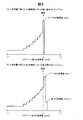
図5は、三角測量で得られる指示体80のZ座標値のヒストグラムの例を示す説明図である。ここで、「三角測量で得られる指示体80のZ座標値」とは、指示体80がスクリーン面SSに接触しているか否かに拘わらず、検出部610(図3)によって検出された指示体80の3次元座標値のうちのZ座標値を意味している。検出部610は、指示体80がスクリーン面SSに接している接触状態と、指示体80がスクリーン面SSに接していない非接触状態のいずれの状態においても、指示体80のZ座標値(正確には、指示体80の先端部のZ座標値)を三角測量で算出する度に、そのZ座標値のヒストグラムを更新する。なお、前述したように、スクリーン面SSのZ座標値Zssは、プロジェクター100の設置後のキャリブレーションにおいて予め較正されている。典型的な例では、このキャリブレーション後のスクリーン面SSのZ座標値Zssは、ゼロに設定される。なお、キャリブレーション後のスクリーン面SSのZ座標値Zssを、「スクリーン面SSの既知のZ座標値」とも呼ぶ。後述するZ座標の補正によってスクリーン面SSのZ座標値が補正されると、その補正後の値が「スクリーン面SSの既知のZ座標値」となる。
FIG. 5 is an explanatory diagram showing an example of a histogram of Z coordinate values of the
図5(A)は、三角測量で得られる指示体80のZ座標値にズレが無い場合に得られるヒストグラムを示している。この例では、図4(A)と整合させるために、図5(A)の左側方向を+Z方向(スクリーン面SSから離れる方向)とし、右側方向を−Z方向(スクリーン面SSの裏側に向かう方向)としている。Z座標値にズレが無い場合には、ヒストグラムのピークを示すZ座標値Zpは、スクリーン面のZ座標値Zss(この例ではZss=0)に等しい。この理由は、ユーザーが指示体80を用いてスクリーン面SS(投写画面PS)上で指示を行う動作を継続してゆくと、指示体80がスクリーン面SSに接触している状態で指示体80の3次元座標値が検出される回数が次第に増加するからである。つまり、スクリーン面SSに接触している状態での指示体80のZ座標値は一定の値(この例では0)となるため、そのZ座標値は、頻度のピークを形成する。
FIG. 5A shows a histogram obtained when there is no deviation in the Z coordinate value of the
図5(B)は、三角測量で得られる指示体80のZ座標値にズレが有る場合に得られるヒストグラムを示している。この例では、ヒストグラムのピークを示すZ座標値Zpは、スクリーン面のZ座標値Zss(=0)よりもマイナス側にずれている。また、ヒストグラムの最小Z座標値Zminは、ピークのZ座標値Zpよりも更にマイナス側に存在する。このような場合には、指示体80の接触検出における検出誤差が増大するので、Z座標を補正することが好ましい。
FIG. 5B shows a histogram obtained when there is a deviation in the Z coordinate value of the
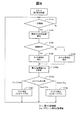
図6は、第1実施形態におけるZ座標補正のフローチャートである。図6の処理の全体は、一定周期毎に実行される(ステップS110)。この一定周期は、例えば毎秒60回〜240回に相当する期間に設定される。以下の説明では、指示体80として指先を用いた場合について説明する。なお、図6の処理の前には、スクリーン面SSの3次元座標に関するキャリブレーションが予め行われているものと仮定する。
FIG. 6 is a flowchart of the Z coordinate correction in the first embodiment. The entire process of FIG. 6 is executed at regular intervals (step S110). This fixed period is set to a period corresponding to, for example, 60 to 240 times per second. In the following description, a case where a fingertip is used as the
ステップS120では、検出部610(図3)が、2台のカメラ310,320を用いた三角測量によって、指先の3次元座標値を検出する。ステップS130では検出部610が、指先がスクリーン面SSに接触しているか否かを判定する。一般には、この判定は以下に従って行われる。
Zmes−Zss ≦ δZth のとき:接触と判定 …(1a)
δZth < Zmes−Zss のとき:非接触と判定 …(1b)
ここで、Zmesは三角測量で検出された指先のZ座標値、Zssはスクリーン面SSの既知のZ座標値、δZthは差分閾値である。
すなわち、接触判定では、指示体のZ座標値Zmesとスクリーン面SSのZ座標値Zssとの差分(Zmes−Zss)が、差分閾値δZth以下であれば接触と判定され、差分閾値δZthより大きければ非接触と判定される。なお、差分閾値δZthとしては、例えば3〜5mmの値が使用される。
In step S120, the detection unit 610 (FIG. 3) detects the three-dimensional coordinate value of the fingertip by triangulation using the two
When Zmes−Zss ≦ δZth: contact is determined (1a)
When δZth <Zmes−Zss: determined as non-contact (1b)
Here, Zmes is a Z coordinate value of the fingertip detected by triangulation, Zss is a known Z coordinate value of the screen surface SS, and δZth is a difference threshold value.
That is, in the contact determination, if the difference (Zmes−Zss) between the Z coordinate value Zmes of the indicator and the Z coordinate value Zss of the screen surface SS is less than or equal to the difference threshold value δZth, it is determined that the contact is made. Determined to be non-contact. For example, a value of 3 to 5 mm is used as the difference threshold δZth.
ステップS130において接触と判定された場合にはステップS140においてタッチ処理が実行され、非接触と判定された場合にはステップS150において非タッチ処理が実行される。ここで、「タッチ処理」とは、指示体が投写画面PSに接触しているときに、その接触位置に応じて行われる各種の処理を意味する。タッチ処理としては、例えば、線図の描画(図2(B))や、ツールの選択等の処理がある。また、「非タッチ処理」とは、指示体が投写画面PSに接触していないときに、指示体の3次元位置に応じて行われる各種の処理を意味する。この非タッチ処理としては、例えば、指示体で利用されているツールについて投写画面PS上における位置を更新して再描画する処理等がある。なお、「非タッチ処理」として何も実行しないものとしてもよい。なお、ステップS140,S150の処理は、投写画像生成部500(図3)によって実行される。 If it is determined in step S130 that contact is made, touch processing is executed in step S140. If it is determined that contact is not made, non-touch processing is executed in step S150. Here, the “touch process” means various processes performed according to the contact position when the indicator is in contact with the projection screen PS. Examples of the touch process include a process of drawing a diagram (FIG. 2B) and a tool selection. The “non-touch process” means various processes performed according to the three-dimensional position of the indicator when the indicator is not in contact with the projection screen PS. As this non-touch process, for example, there is a process of updating the position on the projection screen PS and redrawing the tool used in the indicator. Note that nothing may be executed as the “non-touch process”. Note that the processes of steps S140 and S150 are executed by the projection image generation unit 500 (FIG. 3).
ステップS160では、補正部620(図3)が、ステップS120で得られたZ座標値を用いてヒストグラムを更新する。ステップS170では、補正部620が、ヒストグラムのピークのZ座標値Zpと、スクリーン面SSの既知のZ座標値Zssとを比較し、この比較結果に応じて以下のようにZ座標の補正を行う。
(1)Zss<Zpの場合:Z座標のプラス補正を行う(ステップS180)。具体的には、例えば、スクリーン面SSのZ座標値Zssに+δを加える。
(2)Zss=Zpの場合:Z座標の補正は行わない。
(3)Zp<Zssの場合:Z座標のマイナス補正を行う(ステップS190)。具体的には、例えば、スクリーン面SSのZ座標値Zssに−δを加える。
ここで、「δ」は、Z座標の補正で利用する最小補正単位を意味しており、Z座標値のビット数に応じて予め適宜設定される。例えば、この最小補正単位δは、Z座標値の最下位ビットの「0」と「1」の差分に相当する値としてもよい。
In step S160, the correction unit 620 (FIG. 3) updates the histogram using the Z coordinate value obtained in step S120. In step S170, the correcting
(1) If Zss <Zp: Z coordinate plus correction is performed (step S180). Specifically, for example, + δ is added to the Z coordinate value Zss of the screen surface SS.
(2) When Zss = Zp: The Z coordinate is not corrected.
(3) If Zp <Zss: negative correction of the Z coordinate is performed (step S190). Specifically, for example, −δ is added to the Z coordinate value Zss of the screen surface SS.
Here, “δ” means a minimum correction unit used for correcting the Z coordinate, and is appropriately set in advance according to the number of bits of the Z coordinate value. For example, the minimum correction unit δ may be a value corresponding to the difference between “0” and “1” of the least significant bit of the Z coordinate value.
図5(B)の例に示したように、ピークのZ座標値Zpがスクリーン面SSのZ座標値Zssよりも小さい場合には、ステップS190においてマイナス補正が行われる。この理由は、図5で説明したように、ピークのZ座標値Zpは、指示体80(指先)がスクリーン面SSに接触している状態に対応するものと考えられるので、Zp<Zssとなっている場合にスクリーン面SSのZ座標値Zssをマイナス側に補正すれば正しい値に近づくからである。その後は、この補正後のスクリーン面SSのZ座標値Zssを接触判定に使用すれば、接触判定の精度を向上できる。逆に、ピークのZ座標値Zpがスクリーン面SSのZ座標値Zssよりも大きい場合には、ステップS180においてプラス補正を行うことによって、接触判定の精度を向上できる。 As shown in the example of FIG. 5B, when the Z coordinate value Zp of the peak is smaller than the Z coordinate value Zss of the screen surface SS, negative correction is performed in step S190. The reason for this is that, as described with reference to FIG. 5, the Z coordinate value Zp of the peak is considered to correspond to the state in which the indicator 80 (fingertip) is in contact with the screen surface SS, and therefore, Zp <Zss. This is because if the Z coordinate value Zss of the screen surface SS is corrected to the minus side, the value approaches the correct value. Thereafter, the accuracy of the contact determination can be improved by using the corrected Z coordinate value Zss of the screen surface SS for the contact determination. On the contrary, when the Z coordinate value Zp of the peak is larger than the Z coordinate value Zss of the screen surface SS, the accuracy of the contact determination can be improved by performing positive correction in step S180.
なお、ステップS180,S190では、ピークのZ座標値Zpとスクリーン面SSのZ座標値Zssの差分(Zp−Zss)の大きさに拘わらず、一定の最小補正単位δで補正が行われている。こうすることにより、Z座標が大幅に補正されることに起因して、予期しない不具合(例えば、接触判定と非接触判定とが頻繁に切り替わってしまうこと等)が発生することを防止できる。また、図6の処理は一定周期毎に行われるので、仮に差分(Zp−Zss)がかなり大きな場合にも、図6の処理が複数回繰り返されるに従って、徐々に差分(Zp−Zss)が減少してゼロに近づいてゆくので、実際上の問題はない。但し、ステップS180,S190における補正値としては、最小補正単位δを使用する代わりに、他の補正値を使用しても良い。例えば、補正値として、ピークのZ座標値Zpとスクリーン面SSのZ座標値Zssの差分の絶対値|Zp−Zss|に係数kを乗じた値k|Zp−Zss|を使用してもよい。ここで、係数kとしては、例えば0.6以上1.0以下の範囲の値を使用可能である。こうすれば、より早期にZ座標の補正を完了できる。 In steps S180 and S190, correction is performed in a fixed minimum correction unit δ regardless of the difference (Zp−Zss) between the Z coordinate value Zp of the peak and the Z coordinate value Zss of the screen surface SS. . By doing so, it is possible to prevent unexpected troubles (for example, frequent switching between contact determination and non-contact determination) due to the significant correction of the Z coordinate. Further, since the process of FIG. 6 is performed at regular intervals, even if the difference (Zp−Zss) is considerably large, the difference (Zp−Zss) gradually decreases as the process of FIG. 6 is repeated a plurality of times. As it approaches zero, there is no practical problem. However, as correction values in steps S180 and S190, other correction values may be used instead of using the minimum correction unit δ. For example, a value k | Zp−Zss | obtained by multiplying the absolute value | Zp−Zss | of the difference between the peak Z coordinate value Zp and the Z coordinate value Zss of the screen surface SS by the coefficient k may be used as the correction value. . Here, as the coefficient k, for example, a value in the range of 0.6 to 1.0 can be used. In this way, the correction of the Z coordinate can be completed earlier.
こうして、ステップS170〜S190におけるZ座標の補正処理が終了すると、ステップS110に戻り、上述したステップS110〜S190の処理が一定周期毎に繰り返し実行される。 Thus, when the Z coordinate correction process in steps S170 to S190 is completed, the process returns to step S110, and the processes in steps S110 to S190 described above are repeatedly executed at regular intervals.
なお、Z座標値のデータ数が少ない間はヒストグラムの信頼性が低いため、Z座標の補正(図6のステップS170〜S190)を行わないものとしてもよい。すなわち、Z座標値のデータ数が所定数(例えば100個)を超えた時点以降にZ座標の補正を行うようにしてもよい。また、ステップS120で得られた指示体(指先)のXY座標値が前回から変化していないときには、特殊な事情が発生している可能性があるので、ヒストグラムへの加算以降の処理(ステップS160〜S190)は行わないものとしてもよい。なお、図6の処理は、プロジェクター100の電源が投入されるごとにリセットされても良く、或いは、プロジェクター100の電源が落とされた後も補正後のZ座標値を位置検出部600内の不揮発性メモリー(図示せず)に保持しておくようにしても良い。
Since the histogram reliability is low while the number of Z coordinate value data is small, the Z coordinate correction (steps S170 to S190 in FIG. 6) may not be performed. That is, the Z coordinate may be corrected after the time when the number of data of the Z coordinate value exceeds a predetermined number (for example, 100). Further, when the XY coordinate value of the indicator (fingertip) obtained in step S120 has not changed from the previous time, there is a possibility that a special situation may have occurred, and therefore processing after addition to the histogram (step S160). To S190) may be omitted. 6 may be reset every time the
更に、Z座標の補正は、スクリーン面SS(又は投写画面PS)全体に対して1つのZ座標値を割り当てた状態で実施しても良く、或いは、スクリーン面SS(又は投写画面PS)を複数の小領域に分割して、それぞれの小領域毎に1つのZ座標値を割り当てた状態で実施しても良い。 Further, the correction of the Z coordinate may be performed in a state where one Z coordinate value is assigned to the entire screen surface SS (or projection screen PS), or a plurality of screen surfaces SS (or projection screen PS) may be provided. It is also possible to divide the image into the small areas and assign one Z coordinate value to each small area.
図7は、投写画面PS上におけるZ座標補正の区分の例を示す説明図である。図7(A)の例では、投写画面PSの全体に対して同一のZ座標値が割り当てられており、このZ座標値に対して図6の補正が実行される。図7(B)の例では、投写画面PSが複数(ここでは9つ)の小領域PS1〜PS9に区分されており、これらの小領域PS1〜PS9のそれぞれに対してZ座標の補正が個別に実行される。後者の場合には、図5に示したヒストグラムも個々の小領域PS1〜PS9毎に作成される。なお、投写画面PS(又はスクリーン面SS)を複数の小領域PS1〜PS9に区分した場合には、複数の小領域PS1〜PS9における補正後のZ座標値を補間して、投写画面PS(又はスクリーン面SS)の全体に亘る局所的なZ座標値を求めるようにしても良い。例えば、或る1つの小領域(例えばPS1)の中心から隣の小領域(例えばPS2)の中心に向かって、補間後のZ座標値を直線補間又は多項式近似補間により算出してもよい。このような小領域に区分したZ座標の補正は、以下に説明する他の実施形態にも適用可能である。 FIG. 7 is an explanatory diagram showing an example of the Z coordinate correction classification on the projection screen PS. In the example of FIG. 7A, the same Z coordinate value is assigned to the entire projection screen PS, and the correction of FIG. 6 is performed on this Z coordinate value. In the example of FIG. 7B, the projection screen PS is divided into a plurality (here, nine) of small areas PS1 to PS9, and the Z coordinate correction is individually performed for each of these small areas PS1 to PS9. To be executed. In the latter case, the histogram shown in FIG. 5 is also created for each of the small areas PS1 to PS9. When the projection screen PS (or screen surface SS) is divided into a plurality of small areas PS1 to PS9, the corrected Z coordinate values in the plurality of small areas PS1 to PS9 are interpolated to obtain the projection screen PS (or The local Z coordinate value over the entire screen surface SS) may be obtained. For example, the Z coordinate value after interpolation may be calculated by linear interpolation or polynomial approximation interpolation from the center of one small area (for example, PS1) toward the center of the adjacent small area (for example, PS2). Such correction of the Z coordinate divided into small regions can be applied to other embodiments described below.
なお、図6の処理では、指示体のZ座標値のヒストグラムのピークにおけるZ座標値Zpに基づいてZ座標の補正を行うものとしたが、ヒストグラムから得られる他の特性値を用いてZ座標の補正を行うようにしてもよい。例えば、ヒストグラムのピークにおけるZ座標値Zpと最小Z座標値Zminとの平均値(単純平均又は重み付き平均)を用いてZ座標の補正を行うことも可能である。一般に、指示体のZ座標値のヒストグラムには、指示体がスクリーン面SSに接触している状態が反映されているので、そのヒストグラムに基づいて補正を行うようにすれば、スクリーン面SSに対する指示体の接触の有無を精度良く検出可能である。 In the process of FIG. 6, the Z coordinate is corrected based on the Z coordinate value Zp at the peak of the histogram of the Z coordinate value of the indicator, but the Z coordinate is obtained using other characteristic values obtained from the histogram. May be corrected. For example, it is possible to correct the Z coordinate using an average value (simple average or weighted average) of the Z coordinate value Zp and the minimum Z coordinate value Zmin at the peak of the histogram. In general, since the histogram of the Z coordinate value of the indicator reflects the state in which the indicator is in contact with the screen surface SS, if correction is performed based on the histogram, the instruction to the screen surface SS is indicated. The presence or absence of body contact can be detected with high accuracy.
以上のように、第1実施形態では、指示体のZ座標値のヒストグラムに基づいてスクリーン面のZ座標値Zssを補正するようにしたので、スクリーン面SSに対する指示体の接触検出の精度を向上させることが可能である。 As described above, in the first embodiment, since the Z coordinate value Zss of the screen surface is corrected based on the histogram of the Z coordinate value of the pointer, the contact detection accuracy of the pointer with respect to the screen surface SS is improved. It is possible to make it.
B.第2実施形態
図8は、第2実施形態におけるZ座標補正のフローチャートである。図6に示した第1実施形態との違いは、ステップS160a,S170aだけであり、他のステップは図6と同一である。
B. Second Embodiment FIG. 8 is a flowchart of the Z coordinate correction in the second embodiment. The only difference from the first embodiment shown in FIG. 6 is steps S160a and S170a, and the other steps are the same as those in FIG.
ステップS160aでは、Z座標値のヒストグラムの更新(図6のステップS160)の代わりに、最小Z座標値Zminを必要に応じて更新する。ここで、「最小Z座標値Zmin」とは、図6の処理が複数回繰り返された履歴の中で得られたZ座標値の最小値を意味する。最小Z座標値Zminは、図5(B)のヒストグラムにも現れているが、最小Z座標値Zminを得るためにヒストグラムを作成する必要は無く、単にZ座標値の履歴の中で最小の値を最小Z座標値Zminとして登録すれば良い。ステップS160aにおける最小Z座標値Zminの更新は、ステップS120で得られた指先のZ座標値がそれ以前の最小Z座標値Zminよりも小さい場合にのみ実行される。 In step S160a, instead of updating the histogram of Z coordinate values (step S160 in FIG. 6), the minimum Z coordinate value Zmin is updated as necessary. Here, the “minimum Z coordinate value Zmin” means the minimum value of the Z coordinate value obtained in the history in which the process of FIG. 6 is repeated a plurality of times. Although the minimum Z-coordinate value Zmin also appears in the histogram of FIG. 5B, it is not necessary to create a histogram to obtain the minimum Z-coordinate value Zmin, it is simply the smallest value in the history of Z-coordinate values. May be registered as the minimum Z coordinate value Zmin. The update of the minimum Z coordinate value Zmin in step S160a is executed only when the Z coordinate value of the fingertip obtained in step S120 is smaller than the previous minimum Z coordinate value Zmin.
ステップS170aでは、補正部620が、最小Z座標値Zminと、スクリーン面SSの既知のZ座標値Zssとを比較し、この比較結果に応じて以下のようにZ座標の補正を行う。
(1)Zss<Zminの場合:Z座標のプラス補正を行う(ステップS180)。
(2)Zss=Zminの場合:Z座標の補正は行わない。
(3)Zmin<Zssの場合:Z座標のマイナス補正を行う(ステップS190)。
この補正の結果、第1実施形態と同様に、Z座標値にズレが生じている場合にも、正しい値に補正することが可能となる。
In step S170a, the
(1) If Zss <Zmin: Z coordinate plus correction is performed (step S180).
(2) When Zss = Zmin: The Z coordinate is not corrected.
(3) If Zmin <Zss: negative correction of the Z coordinate is performed (step S190).
As a result of this correction, similarly to the first embodiment, even when a deviation occurs in the Z coordinate value, it can be corrected to a correct value.
第2実施形態で最小Z座標値Zminを用いている理由は、この最小Z座標値ZminがヒストグラムのピークのZ座標値Zpとほとんど同じで両者の差は十分に小さいので、両者のいずれを用いてもほぼ同様の補正効果が得られるからである。また、最小Z座標値Zminを利用する場合には、ヒストグラムを作成する必要が無いので、処理がより簡単であるという利点がある。 The reason why the minimum Z coordinate value Zmin is used in the second embodiment is that the minimum Z coordinate value Zmin is almost the same as the Z coordinate value Zp of the peak of the histogram and the difference between them is sufficiently small. However, almost the same correction effect can be obtained. Further, when the minimum Z coordinate value Zmin is used, there is an advantage that the process is simpler because it is not necessary to create a histogram.
このように、第2実施形態では、三角測量で得られた指示体の最小Z座標値Zminに基づいて、Z座標の補正を実行するようにしたので、指示体の接触検出の検出精度を向上させることが可能である。なお、最小Z座標値Zminは、三角測量で得られる指示体のZ座標値の履歴から決まる特性であるという意味では、第1実施形態で用いたヒストグラムと共通している。従って、第1実施形態と第2実施形態は、指示体のZ座標値の履歴に基づいてスクリーン面のZ座標値Zssを補正するという点で共通していることが理解できる。 As described above, in the second embodiment, since the Z coordinate is corrected based on the minimum Z coordinate value Zmin of the indicator obtained by triangulation, the detection accuracy of the contact detection of the indicator is improved. It is possible to make it. The minimum Z coordinate value Zmin is common to the histogram used in the first embodiment in the sense that it is a characteristic determined from the history of the Z coordinate value of the indicator obtained by triangulation. Therefore, it can be understood that the first embodiment and the second embodiment are common in that the Z coordinate value Zss of the screen surface is corrected based on the history of the Z coordinate value of the indicator.
C.第3実施形態
図9は、第3実施形態におけるZ座標補正のフローチャートである。図6に示した第1実施形態との違いは、ステップS140,S150とステップS160との間に、ステップS155を追加した点だけであり、他のステップは図6と同一である。
C. Third Embodiment FIG. 9 is a flowchart of the Z coordinate correction in the third embodiment. The only difference from the first embodiment shown in FIG. 6 is that step S155 is added between steps S140 and S150 and step S160, and the other steps are the same as in FIG.
ステップS155では、補正部620が、指先のZ方向速度がゼロか否かを判断し、指先のZ方向速度がゼロである場合にはステップS160以降のZ座標補正処理を実行し、一方、指先のZ方向速度がゼロでない場合にはZ座標補正処理を行わずにステップS110に戻る。なお、指先のZ方向速度がゼロか否かは、今回のステップS120で得られた指先のZ座標値と、前回の図6の処理においてステップS120で得られた指先のZ座標値との差分がゼロか否かに応じて判定できる。なお、Z方向速度がゼロか否かの判定を
厳密に行う必要はなく、Z方向速度の絶対値が微小な許容誤差以下である場合にはZ方向速度がゼロであると判定しても良い。
In step S155, the
第3実施形態において指先のZ方向速度がゼロである場合にのみステップS160以降のZ座標補正処理を実行する理由は、指先がスクリーン面SSに接触しているときには指先のZ方向速度がゼロになっていると考えられるからである。第3実施形態では、指先のZ方向速度がゼロの場合に得られたZ座標値のヒストグラムが作成されるので、Z座標の補正の信頼性を第1実施形態よりも高めることが可能である。なお、図8に示した第2実施形態においても、第3実施形態と同様に、指先のZ方向速度がゼロの場合にのみステップS160a以降のZ座標補正処理を実行するようにしても良い。 The reason why the Z coordinate correction processing after step S160 is executed only when the Z-direction velocity of the fingertip is zero in the third embodiment is that the Z-direction velocity of the fingertip is zero when the fingertip is in contact with the screen surface SS. It is because it is thought that it has become. In the third embodiment, since a histogram of Z coordinate values obtained when the Z-direction velocity of the fingertip is zero is created, it is possible to improve the reliability of correction of the Z coordinate compared to the first embodiment. . In the second embodiment shown in FIG. 8, as in the third embodiment, the Z coordinate correction process after step S160a may be executed only when the Z-direction velocity of the fingertip is zero.
・変形例:
なお、この発明は上記の実施例や実施形態に限られるものではなく、その要旨を逸脱しない範囲において種々の態様において実施することが可能であり、例えば次のような変形も可能である。
・ Modification:
The present invention is not limited to the above-described examples and embodiments, and can be implemented in various modes without departing from the gist thereof. For example, the following modifications are possible.
・変形例1:
上記実施形態では、指先(非発光指示体80)を用いた場合にZ座標の補正を行うものとしていたが、自発光指示体70を用いた場合にも同様にZ座標の補正を行うものとしてもよい。例えば、ユーザーが自発光指示体70を用いているか非発光指示体80を用いているかに拘わらず、図6,図8,又は図9で説明した処理を実行して、Z座標の補正を行うものとしてもよい。但し、自発光指示体70に関しては、先端スイッチ76(図3)のオン/オフに応じて接触判定を行うことも可能なので、上述したZ座標の補正の効果は非発光指示体80を用いた場合により顕著である。
・ Modification 1:
In the above embodiment, the Z coordinate is corrected when the fingertip (non-light emitting indicator 80) is used. However, the Z coordinate is corrected similarly when the self
・変形例2:
Z座標の補正の方法としては、以下のような種々の方法のいずれかを採用することが可能である。
(a)スクリーン面SSのZ座標値Zssを補正する(第1実施形態)。
(b)三角測量により得られる指示体のZ座標値を補正する。
(c)指示体の接触判定で使用される差分閾値δZthを補正する。
(d)上記(a)〜(c)のうちの2つ以上を同時に行う。
なお、Z座標の補正は、スクリーン面SSに対する指示体の接触検出の検出精度を高めるために行われるので、これらの方法(a)〜(d)のいずれを採用しても、ほぼ同じ効果が得られる。但し、上記(a)〜(c)のうちの2つを同時に行う場合には、1回に補正されるZ座標値が最小補正単位δの2倍となる。一方、上記(a)〜(c)のいずれか1つのみを実行するようにすれば、1回に補正されるZ座標値が最小補正単位δとなるので、1回当たりの補正量を小さくすることが可能であり、予期しない過補正を防止できる。
Modification 2
As a method for correcting the Z coordinate, any of the following various methods can be employed.
(A) The Z coordinate value Zss of the screen surface SS is corrected (first embodiment).
(B) The Z coordinate value of the indicator obtained by triangulation is corrected.
(C) The difference threshold value δZth used in the contact determination of the indicator is corrected.
(D) Two or more of the above (a) to (c) are performed simultaneously.
Since the correction of the Z coordinate is performed in order to increase the detection accuracy of the contact detection of the indicator with respect to the screen surface SS, the same effect can be obtained regardless of which of these methods (a) to (d). can get. However, when two of the above (a) to (c) are performed simultaneously, the Z coordinate value corrected at one time is twice the minimum correction unit δ. On the other hand, if only one of the above (a) to (c) is executed, the Z coordinate value corrected at one time becomes the minimum correction unit δ, so that the correction amount per time is reduced. It is possible to prevent unexpected overcorrection.
・変形例3:
上記実施形態では、投写画面PAが平面状のスクリーン面SSに投写されるものとしていたが、投写画面PSが曲面状のスクリーン面SSに投写されるものとしても良い。この場合にも、2台のカメラで撮像された画像を用い、三角測量を利用して指示体の先端部の3次元位置を決定できるので、指示体の先端部と投写画面の位置関係を決定することが可能である。また、曲面状のスクリーン面SSを利用する場合には、図7(B)で示したように、投写画面PS(又はスクリーン面SS)を複数の小領域に区分し、各小領域に関してZ座標を補正することにより、接触検出の精度をより高めることが可能である。
・ Modification 3:
In the above embodiment, the projection screen PA is projected onto the flat screen surface SS. However, the projection screen PS may be projected onto the curved screen surface SS. Also in this case, since the three-dimensional position of the tip of the indicator can be determined using triangulation using the images captured by the two cameras, the positional relationship between the tip of the indicator and the projection screen is determined. Is possible. When the curved screen surface SS is used, the projection screen PS (or the screen surface SS) is divided into a plurality of small areas as shown in FIG. It is possible to further improve the accuracy of contact detection.
・変形例4:
上記実施形態では、投写画面PSの領域(画像が投写される投写範囲)を撮像する撮像部300が2台のカメラ310,320を有しているものとしたが、撮像部300は3台以上のカメラを有していてもよい。後者の場合には、m台(mは3以上の整数)のカメラで撮像されたm個の画像に基づいて、指示体の3次元座標(X,Y,Z)が決定される。例えば、m個の画像から2個の画像を任意に選択して得られるmC2個の組み合わせを用いてそれぞれ3次元座標を求め、それらの平均値を用いて最終的な3次元座標を決定しても良い。こうすれば、3次元座標の検出精度を更に高めることが可能である。
-Modification 4:
In the above embodiment, the
・変形例5:
上記実施形態では、複数台のカメラを用い、三角測量によって指示体の3次元座標を検出していたが、これ以外の手段を用いて指示体の3次元座標の検出を行うようにしてもよい。指示体の3次元座標を検出する他の手段としては、例えば、対象物に構造化光を投影して撮像する方式や、ToF(Time of Flight)方式を採用することが可能である。
Modification 5:
In the above embodiment, the three-dimensional coordinates of the indicator are detected by triangulation using a plurality of cameras. However, the three-dimensional coordinates of the indicator may be detected using other means. . As other means for detecting the three-dimensional coordinates of the indicator, for example, a method of projecting structured light onto an object and imaging, or a ToF (Time of Flight) method can be adopted.
以上、いくつかの実施例に基づいて本発明の実施の形態について説明してきたが、上記した発明の実施の形態は、本発明の理解を容易にするためのものであり、本発明を限定するものではない。本発明は、その趣旨並びに特許請求の範囲を逸脱することなく、変更、改良され得るとともに、本発明にはその等価物が含まれることはもちろんである。 The embodiments of the present invention have been described above based on some examples. However, the above-described embodiments of the present invention are for facilitating the understanding of the present invention and limit the present invention. It is not a thing. The present invention can be changed and improved without departing from the spirit and scope of the claims, and it is needless to say that the present invention includes equivalents thereof.
70…自発光指示体,71…先端部,72…軸部,73…ボタンスイッチ,74…信号光受信部,75…制御部,76…先端スイッチ,77…先端発光部,80…非発光指示体,81…先端部,100…インタラクティブプロジェクター,200…投写部,210…投写レンズ,220…光変調部,230…光源,300…撮像部,310…第1カメラ,320…第2カメラ,410…検出光照射部,430…信号光送信部,500…投写画像生成部,510…投写画像メモリー,600…位置検出部,610…検出部,620…補正部,700…制御部,900…インタラクティブプロジェクションシステム,910…支持部材,920…スクリーン板
DESCRIPTION OF
Claims (6)
スクリーン面に画像を投写する投写部と、
前記指示体の3次元座標値を検出すると共に、前記スクリーン面から離れる方向の座標をZ座標としたとき、前記指示体のZ座標値と前記スクリーン面のZ座標値との間の差分と予め設定された差分閾値との関係に基づいて前記スクリーン面に対する前記指示体の接触の有無を検出する検出部と、
前記指示体のZ座標値の履歴に基づいて、前記スクリーン面のZ座標値の補正をする補正部と、
を備え、
前記補正部は、前記指示体のZ座標値の履歴のデータ数が所定数より少ない間は、前記補正を行なわず、
前記補正部は、前記指示体のZ座標値のヒストグラムに基づいて前記補正を行い、
前記補正部は、
前記指示体のXY座標値が前回から変化しているときは、前記指示体のZ座標値を前記ヒストグラムに加算する加算処理を行ない、
前記指示体のXY座標値が前回から変化していないときには、前記加算処理を行なわず、前記補正を行なわない、
インタラクティブプロジェクター。 An interactive projector for detecting the position of an indicator,
A projection unit that projects an image on a screen surface;
When the three-dimensional coordinate value of the indicator is detected and the coordinate in the direction away from the screen surface is the Z coordinate, the difference between the Z coordinate value of the indicator and the Z coordinate value of the screen surface is determined in advance. A detection unit that detects presence or absence of contact of the indicator with the screen surface based on a relationship with a set difference threshold;
A correction unit that corrects the Z coordinate value of the screen surface based on the history of the Z coordinate value of the indicator;
With
The correction unit does not perform the correction while the number of data of the Z coordinate value history of the indicator is less than a predetermined number ,
The correction unit performs the correction based on a histogram of the Z coordinate value of the indicator,
The correction unit is
When the XY coordinate value of the indicator has changed from the previous time, an addition process for adding the Z coordinate value of the indicator to the histogram is performed,
When the XY coordinate value of the indicator has not changed from the previous time, the addition process is not performed and the correction is not performed.
Interactive projector.
前記スクリーン面のうちで前記画像が投写される投写範囲を撮像する複数台のカメラをさらに備え、
前記検出部は、前記複数台のカメラによって撮像された前記指示体を含む複数の画像を用いた三角測量により前記指示体の3次元座標値を検出する、インタラクティブプロジェクター。 The interactive projector according to claim 1,
A plurality of cameras for capturing a projection range in which the image is projected on the screen surface;
The said detection part is an interactive projector which detects the three-dimensional coordinate value of the said indicator by the triangulation using the some image containing the said indicator imaged with the said several cameras.
前記補正部は、前記指示体のZ座標値のヒストグラムのピークを示すZ座標値と、前記スクリーン面のZ座標値との大小関係に応じて前記補正を行う、インタラクティブプロジェクター。 The interactive projector according to claim 1 or 2 ,
The interactive projector, wherein the correction unit performs the correction according to a magnitude relationship between a Z coordinate value indicating a peak of a histogram of the Z coordinate value of the indicator and a Z coordinate value of the screen surface.
前記補正部は、前記指示体のZ方向速度がゼロであるときの前記指示体のZ座標値の履歴に基づいて前記補正を行う、インタラクティブプロジェクター。 An interactive projector according to any one of claims 1 to 3 ,
The interactive projector, wherein the correction unit performs the correction based on a history of Z coordinate values of the indicator when the Z direction speed of the indicator is zero.
前記検出部は、前記指示体が前記スクリーン面に接している接触状態と前記指示体が前記スクリーン面に接していない非接触状態のいずれの状態においても、前記指示体のZ座標値を算出する時、前記履歴を更新する、インタラクティブプロジェクター。 An interactive projector according to any one of claims 1 to 4 ,
The detection unit calculates a Z coordinate value of the indicator in any of a contact state where the indicator is in contact with the screen surface and a non-contact state where the indicator is not in contact with the screen surface. When the interactive projector updates the history.
(a)前記指示体の3次元座標値を検出すると共に、スクリーン面から離れる方向の座標をZ座標としたとき、前記指示体のZ座標値と前記スクリーン面のZ座標値との間の差分と予め設定された差分閾値との関係に基づいて前記スクリーン面に対する前記指示体の接触の有無を検出する工程と、
(b)前記指示体のZ座標値の履歴に基づいて、前記スクリーン面のZ座標値の補正をする工程と、
を備え、
前記工程(b)において、前記指示体のZ座標値の履歴のデータ数が所定数より少ない間は、前記補正を行なわず、
前記工程(b)において、前記指示体のZ座標値のヒストグラムに基づいて前記補正を行い、
前記工程(b)において、
前記指示体のXY座標値が前回から変化しているときは、前記指示体のZ座標値を前記ヒストグラムに加算する加算処理を行ない、
前記指示体のXY座標値が前回から変化していないときには、前記加算処理を行なわず、前記補正を行なわない、
補正方法。 A method for correcting the Z coordinate of an interactive projector capable of detecting the position of an indicator using a plurality of cameras for imaging a projection range,
(A) When the three-dimensional coordinate value of the indicator is detected and the coordinate in the direction away from the screen surface is the Z coordinate, the difference between the Z coordinate value of the indicator and the Z coordinate value of the screen surface Detecting the presence or absence of contact of the indicator with respect to the screen surface based on a relationship between the threshold value and a preset difference threshold value;
(B) on the basis of the history of the Z coordinate value of the pointer, the step of correcting the Z-coordinate values of the screen surface,
With
In the step (b), while the number of data of the Z coordinate value history of the indicator is less than a predetermined number, the correction is not performed ,
In the step (b), the correction is performed based on a histogram of the Z coordinate value of the indicator,
In the step (b),
When the XY coordinate value of the indicator has changed from the previous time, an addition process for adding the Z coordinate value of the indicator to the histogram is performed,
When the XY coordinate value of the indicator has not changed from the previous time, the addition process is not performed and the correction is not performed.
Correction method.
Priority Applications (2)
| Application Number | Priority Date | Filing Date | Title |
|---|---|---|---|
| JP2015151578A JP6569361B2 (en) | 2015-07-31 | 2015-07-31 | Interactive projector and method for correcting Z coordinate thereof |
| US15/198,423 US9971419B2 (en) | 2015-07-31 | 2016-06-30 | Interactive projector and method of correcting Z-coordinate of the same |
Applications Claiming Priority (1)
| Application Number | Priority Date | Filing Date | Title |
|---|---|---|---|
| JP2015151578A JP6569361B2 (en) | 2015-07-31 | 2015-07-31 | Interactive projector and method for correcting Z coordinate thereof |
Publications (3)
| Publication Number | Publication Date |
|---|---|
| JP2017033222A JP2017033222A (en) | 2017-02-09 |
| JP2017033222A5 JP2017033222A5 (en) | 2018-08-16 |
| JP6569361B2 true JP6569361B2 (en) | 2019-09-04 |
Family
ID=57883485
Family Applications (1)
| Application Number | Title | Priority Date | Filing Date |
|---|---|---|---|
| JP2015151578A Active JP6569361B2 (en) | 2015-07-31 | 2015-07-31 | Interactive projector and method for correcting Z coordinate thereof |
Country Status (2)
| Country | Link |
|---|---|
| US (1) | US9971419B2 (en) |
| JP (1) | JP6569361B2 (en) |
Families Citing this family (1)
| Publication number | Priority date | Publication date | Assignee | Title |
|---|---|---|---|---|
| CN108071909B (en) * | 2017-12-07 | 2020-05-26 | 联想(北京)有限公司 | Touch interaction device |
Family Cites Families (10)
| Publication number | Priority date | Publication date | Assignee | Title |
|---|---|---|---|---|
| JP2000231446A (en) * | 1999-02-10 | 2000-08-22 | Sharp Corp | Display integrated type tablet device and storage medium stored with automatic tablet correction program |
| US6803906B1 (en) * | 2000-07-05 | 2004-10-12 | Smart Technologies, Inc. | Passive touch system and method of detecting user input |
| JP2009251702A (en) * | 2008-04-02 | 2009-10-29 | Hiroyuki Hosoda | Information processing unit, information processing method, and information processing program |
| JP4797062B2 (en) * | 2008-12-25 | 2011-10-19 | 株式会社コナミデジタルエンタテインメント | Input reception device, correction information calculation method, and program |
| US9019239B2 (en) * | 2010-11-29 | 2015-04-28 | Northrop Grumman Systems Corporation | Creative design systems and methods |
| JP2012150636A (en) | 2011-01-19 | 2012-08-09 | Seiko Epson Corp | Projection type display device and information processing system |
| JP5845582B2 (en) * | 2011-01-19 | 2016-01-20 | セイコーエプソン株式会社 | Position detection system, display system, and information processing system |
| JP6102330B2 (en) * | 2013-02-22 | 2017-03-29 | 船井電機株式会社 | projector |
| JP2014170149A (en) * | 2013-03-05 | 2014-09-18 | Funai Electric Co Ltd | Projector |
| JP5850970B2 (en) * | 2014-04-09 | 2016-02-03 | 株式会社東芝 | Information processing apparatus, video projection apparatus, information processing method, and program |
-
2015
- 2015-07-31 JP JP2015151578A patent/JP6569361B2/en active Active
-
2016
- 2016-06-30 US US15/198,423 patent/US9971419B2/en active Active
Also Published As
| Publication number | Publication date |
|---|---|
| JP2017033222A (en) | 2017-02-09 |
| US9971419B2 (en) | 2018-05-15 |
| US20170034490A1 (en) | 2017-02-02 |
Similar Documents
| Publication | Publication Date | Title |
|---|---|---|
| JP6477131B2 (en) | Interactive projector, interactive projection system, and control method of interactive projector | |
| JP6623812B2 (en) | Position detecting device and contrast adjusting method thereof | |
| JP6477130B2 (en) | Interactive projector and interactive projection system | |
| US20160282968A1 (en) | Interactive projector and interactive projection system | |
| US11073949B2 (en) | Display method, display device, and interactive projector configured to receive an operation to an operation surface by a hand of a user | |
| CN107407995B (en) | Interactive projector, interactive projection system, and control method for interactive projector | |
| JP6459706B2 (en) | Interactive projector and interactive projection system | |
| JP6485160B2 (en) | Interactive projector and interactive projector control method | |
| JP6569361B2 (en) | Interactive projector and method for correcting Z coordinate thereof | |
| JP6631280B2 (en) | Position detecting device, position detecting system, and position detecting method | |
| JP2017138774A (en) | Position detection device, position detection system, and position detection method | |
| JP2016186677A (en) | Interactive projection system, pointing element, and method for controlling interactive projection system | |
| JP6451446B2 (en) | Interactive projector and interactive projection system | |
| JP2017027424A (en) | Interactive projector and method of detecting installation state thereof | |
| JP2016186678A (en) | Interactive projector and method for controlling interactive projector | |
| JP2018132912A (en) | Position detection device, and position detection method | |
| JP2016186679A (en) | Interactive projector and method for controlling interactive projector | |
| JP6690271B2 (en) | Position detection system, position detection device, and position detection method | |
| JP2019106105A (en) | Interactive projection system, interactive projector, and method for controlling interactive projector | |
| WO2018211659A1 (en) | Operation detection device, video display device equipped with same, and video display method | |
| JP2019106106A (en) | Interactive projection system, interactive projector, and method for controlling interactive projector | |
| JP2018132911A (en) | Position detection device, and method for adjusting intensity of detection light |
Legal Events
| Date | Code | Title | Description |
|---|---|---|---|
| A521 | Request for written amendment filed |
Free format text: JAPANESE INTERMEDIATE CODE: A523 Effective date: 20180709 |
|
| A621 | Written request for application examination |
Free format text: JAPANESE INTERMEDIATE CODE: A621 Effective date: 20180709 |
|
| A977 | Report on retrieval |
Free format text: JAPANESE INTERMEDIATE CODE: A971007 Effective date: 20190131 |
|
| A131 | Notification of reasons for refusal |
Free format text: JAPANESE INTERMEDIATE CODE: A131 Effective date: 20190212 |
|
| A521 | Request for written amendment filed |
Free format text: JAPANESE INTERMEDIATE CODE: A523 Effective date: 20190328 |
|
| A131 | Notification of reasons for refusal |
Free format text: JAPANESE INTERMEDIATE CODE: A131 Effective date: 20190423 |
|
| A521 | Request for written amendment filed |
Free format text: JAPANESE INTERMEDIATE CODE: A523 Effective date: 20190617 |
|
| TRDD | Decision of grant or rejection written | ||
| A01 | Written decision to grant a patent or to grant a registration (utility model) |
Free format text: JAPANESE INTERMEDIATE CODE: A01 Effective date: 20190709 |
|
| A61 | First payment of annual fees (during grant procedure) |
Free format text: JAPANESE INTERMEDIATE CODE: A61 Effective date: 20190722 |
|
| R150 | Certificate of patent or registration of utility model |
Ref document number: 6569361 Country of ref document: JP Free format text: JAPANESE INTERMEDIATE CODE: R150 |