JP6623812B2 - Position detecting device and contrast adjusting method thereof - Google Patents
Position detecting device and contrast adjusting method thereof Download PDFInfo
- Publication number
- JP6623812B2 JP6623812B2 JP2016027490A JP2016027490A JP6623812B2 JP 6623812 B2 JP6623812 B2 JP 6623812B2 JP 2016027490 A JP2016027490 A JP 2016027490A JP 2016027490 A JP2016027490 A JP 2016027490A JP 6623812 B2 JP6623812 B2 JP 6623812B2
- Authority
- JP
- Japan
- Prior art keywords
- unit
- operation surface
- light
- irradiation unit
- contrast
- Prior art date
- Legal status (The legal status is an assumption and is not a legal conclusion. Google has not performed a legal analysis and makes no representation as to the accuracy of the status listed.)
- Active
Links
Images


Classifications
-
- G—PHYSICS
- G06—COMPUTING; CALCULATING OR COUNTING
- G06F—ELECTRIC DIGITAL DATA PROCESSING
- G06F3/00—Input arrangements for transferring data to be processed into a form capable of being handled by the computer; Output arrangements for transferring data from processing unit to output unit, e.g. interface arrangements
- G06F3/01—Input arrangements or combined input and output arrangements for interaction between user and computer
- G06F3/03—Arrangements for converting the position or the displacement of a member into a coded form
- G06F3/041—Digitisers, e.g. for touch screens or touch pads, characterised by the transducing means
- G06F3/0416—Control or interface arrangements specially adapted for digitisers
-
- H—ELECTRICITY
- H04—ELECTRIC COMMUNICATION TECHNIQUE
- H04N—PICTORIAL COMMUNICATION, e.g. TELEVISION
- H04N9/00—Details of colour television systems
- H04N9/12—Picture reproducers
- H04N9/31—Projection devices for colour picture display, e.g. using electronic spatial light modulators [ESLM]
- H04N9/3141—Constructional details thereof
-
- G—PHYSICS
- G06—COMPUTING; CALCULATING OR COUNTING
- G06F—ELECTRIC DIGITAL DATA PROCESSING
- G06F3/00—Input arrangements for transferring data to be processed into a form capable of being handled by the computer; Output arrangements for transferring data from processing unit to output unit, e.g. interface arrangements
- G06F3/01—Input arrangements or combined input and output arrangements for interaction between user and computer
- G06F3/03—Arrangements for converting the position or the displacement of a member into a coded form
- G06F3/041—Digitisers, e.g. for touch screens or touch pads, characterised by the transducing means
- G06F3/0416—Control or interface arrangements specially adapted for digitisers
- G06F3/0418—Control or interface arrangements specially adapted for digitisers for error correction or compensation, e.g. based on parallax, calibration or alignment
-
- G—PHYSICS
- G06—COMPUTING; CALCULATING OR COUNTING
- G06F—ELECTRIC DIGITAL DATA PROCESSING
- G06F3/00—Input arrangements for transferring data to be processed into a form capable of being handled by the computer; Output arrangements for transferring data from processing unit to output unit, e.g. interface arrangements
- G06F3/01—Input arrangements or combined input and output arrangements for interaction between user and computer
- G06F3/03—Arrangements for converting the position or the displacement of a member into a coded form
- G06F3/041—Digitisers, e.g. for touch screens or touch pads, characterised by the transducing means
- G06F3/042—Digitisers, e.g. for touch screens or touch pads, characterised by the transducing means by opto-electronic means
- G06F3/0421—Digitisers, e.g. for touch screens or touch pads, characterised by the transducing means by opto-electronic means by interrupting or reflecting a light beam, e.g. optical touch-screen
-
- G—PHYSICS
- G06—COMPUTING; CALCULATING OR COUNTING
- G06F—ELECTRIC DIGITAL DATA PROCESSING
- G06F3/00—Input arrangements for transferring data to be processed into a form capable of being handled by the computer; Output arrangements for transferring data from processing unit to output unit, e.g. interface arrangements
- G06F3/01—Input arrangements or combined input and output arrangements for interaction between user and computer
- G06F3/03—Arrangements for converting the position or the displacement of a member into a coded form
- G06F3/041—Digitisers, e.g. for touch screens or touch pads, characterised by the transducing means
- G06F3/042—Digitisers, e.g. for touch screens or touch pads, characterised by the transducing means by opto-electronic means
- G06F3/0425—Digitisers, e.g. for touch screens or touch pads, characterised by the transducing means by opto-electronic means using a single imaging device like a video camera for tracking the absolute position of a single or a plurality of objects with respect to an imaged reference surface, e.g. video camera imaging a display or a projection screen, a table or a wall surface, on which a computer generated image is displayed or projected
-
- G—PHYSICS
- G06—COMPUTING; CALCULATING OR COUNTING
- G06T—IMAGE DATA PROCESSING OR GENERATION, IN GENERAL
- G06T7/00—Image analysis
- G06T7/70—Determining position or orientation of objects or cameras
-
- H—ELECTRICITY
- H04—ELECTRIC COMMUNICATION TECHNIQUE
- H04N—PICTORIAL COMMUNICATION, e.g. TELEVISION
- H04N9/00—Details of colour television systems
- H04N9/12—Picture reproducers
- H04N9/31—Projection devices for colour picture display, e.g. using electronic spatial light modulators [ESLM]
- H04N9/3141—Constructional details thereof
- H04N9/315—Modulator illumination systems
- H04N9/3155—Modulator illumination systems for controlling the light source
-
- H—ELECTRICITY
- H04—ELECTRIC COMMUNICATION TECHNIQUE
- H04N—PICTORIAL COMMUNICATION, e.g. TELEVISION
- H04N9/00—Details of colour television systems
- H04N9/12—Picture reproducers
- H04N9/31—Projection devices for colour picture display, e.g. using electronic spatial light modulators [ESLM]
- H04N9/3179—Video signal processing therefor
- H04N9/3188—Scale or resolution adjustment
-
- H—ELECTRICITY
- H04—ELECTRIC COMMUNICATION TECHNIQUE
- H04N—PICTORIAL COMMUNICATION, e.g. TELEVISION
- H04N9/00—Details of colour television systems
- H04N9/12—Picture reproducers
- H04N9/31—Projection devices for colour picture display, e.g. using electronic spatial light modulators [ESLM]
- H04N9/3191—Testing thereof
- H04N9/3194—Testing thereof including sensor feedback
-
- G—PHYSICS
- G06—COMPUTING; CALCULATING OR COUNTING
- G06F—ELECTRIC DIGITAL DATA PROCESSING
- G06F2203/00—Indexing scheme relating to G06F3/00 - G06F3/048
- G06F2203/041—Indexing scheme relating to G06F3/041 - G06F3/045
- G06F2203/04104—Multi-touch detection in digitiser, i.e. details about the simultaneous detection of a plurality of touching locations, e.g. multiple fingers or pen and finger
-
- G—PHYSICS
- G06—COMPUTING; CALCULATING OR COUNTING
- G06T—IMAGE DATA PROCESSING OR GENERATION, IN GENERAL
- G06T2207/00—Indexing scheme for image analysis or image enhancement
- G06T2207/10—Image acquisition modality
- G06T2207/10016—Video; Image sequence
-
- G—PHYSICS
- G06—COMPUTING; CALCULATING OR COUNTING
- G06T—IMAGE DATA PROCESSING OR GENERATION, IN GENERAL
- G06T2207/00—Indexing scheme for image analysis or image enhancement
- G06T2207/10—Image acquisition modality
- G06T2207/10141—Special mode during image acquisition
- G06T2207/10152—Varying illumination
Description
本発明は、操作面上における指示体の指示位置を検出可能な位置検出装置に関する。 The present invention relates to a position detection device that can detect a pointing position of a pointer on an operation surface.
特許文献1には、位置検出装置としての機能を有するインタラクティブプロジェクターが開示されている。このインタラクティブプロジェクターは、投写画面をスクリーンに投写するとともに、発光ペンや指などの指示体(pointing element)を含む画像をカメラで撮像し、この撮像画像を用いて指示体の指示位置を検出することが可能である。すなわち、インタラクティブプロジェクターは、対象物の先端がスクリーンに接しているときに投写画面に対して描画等の所定の指示が入力されているものと認識し、その指示に応じて投写画面を再描画する。従って、ユーザーは、投写画面をユーザーインターフェースとして用いて、各種の指示を入力することが可能である。 Patent Literature 1 discloses an interactive projector having a function as a position detection device. This interactive projector projects a projection screen on a screen, captures an image including a pointing element such as a light emitting pen or a finger with a camera, and detects a pointing position of the pointer using the captured image. Is possible. That is, the interactive projector recognizes that a predetermined instruction such as drawing is input to the projection screen when the tip of the object is in contact with the screen, and redraws the projection screen in accordance with the instruction. . Therefore, the user can input various instructions using the projection screen as a user interface.
インタラクティブプロジェクターでは、指示体の指示位置を検出するために、赤外光などの検出光を指示体に照射し、指示体で反射された検出光をカメラで撮像する。撮像された画像から指示体の指示位置を検出する際には、指示体と投写画面のコントラストの差を利用して指示体が画像内のどこにあるかが判定される。このため、カメラで撮像される画像では、指示体と投写画面のコントラストの差が十分に大きなことが望まれる。 In the interactive projector, in order to detect a pointing position of the pointer, detection light such as infrared light is applied to the pointer, and the detection light reflected by the pointer is imaged by a camera. When detecting the pointing position of the pointer from the captured image, it is determined where in the image the pointer is located by using the contrast difference between the pointer and the projection screen. Therefore, it is desired that the difference in contrast between the pointer and the projection screen be sufficiently large in an image captured by the camera.
しかしながら、本願の発明者は、指示体と投写画面のコンストラストを十分に大きくすることが必ずしも容易ではなく、検出光の照射状態によっては、コントラストが十分に得られない場合があることを見いだした。このような問題は、インタラクティブプロジェクターに限らず、一般に、操作面上で指示体により指示された指示位置を検出する位置検出装置に共通する問題である。 However, the inventor of the present application has found that it is not always easy to sufficiently increase the contrast between the pointer and the projection screen, and that depending on the irradiation state of the detection light, sufficient contrast may not be obtained. . Such a problem is not limited to the interactive projector, but is generally a problem common to a position detection device that detects a designated position designated by a pointer on an operation surface.
本発明は、上述の課題の少なくとも一部を解決するためになされたものであり、以下の形態又は適用例として実現することが可能である。
<第1形態>
本発明の第1形態は、操作面上で指示体により指示された指示位置を検出する位置検出装置であって、前記操作面に検出光を照射する第1照射部及び第2照射部と、前記操作面を撮像する撮像部と、前記撮像部で撮像された撮像画像に基づいて、前記指示体により指示された指示位置を検出する検出部と、を備え、前記第1照射部は、前記第2照射部よりも前記操作面に近い側に配置され、前記第2照射部よりも発光強度が強く、前記第1照射部及び前記第2照射部の発光強度は、前記第1照射部の発光時に得られる第1コントラストが閾値を超える第1領域と、前記第2照射部の発光時に得られる第2コントラストが閾値を超える第2領域との和が、前記操作面の全領域を包含するように調整されている。
この第1形態の位置検出装置によれば、操作面により近い第1照射部の発光強度が第2照射部の発光強度よりも強いので、十分なコントラストを得ることができ、撮像画像から指示体の指示位置を決定できる。また、操作面の全領域において、指示体を明瞭に識別することが可能となる。
<第2形態>
本発明の第2形態は、操作面上で指示体により指示された指示位置を検出する位置検出装置であって、前記操作面に検出光を照射する第1照射部及び第2照射部と、前記操作面を撮像する撮像部と、前記撮像部で撮像された撮像画像に基づいて、前記指示体により指示された指示位置を検出する検出部と、前記第1照射部及び前記第2照射部の少なくとも一方の発光強度を調整することによって、前記撮像画像における前記指示体と前記操作面との間のコントラストが閾値を超えるように調整する調整部と、を備え、前記第1照射部及び前記第2照射部の発光強度は、前記第1照射部の発光時に得られる第1コントラストが閾値を超える第1領域と、前記第2照射部の発光時に得られる第2コントラストが閾値を超える第2領域との和が、前記操作面の全領域を包含するように調整される。
この第2形態の位置検出装置によれば、調整部が第1照射部と第2照射部の発光強度を調整することによって十分なコントラストを得ることができ、撮像画像から指示体の指示位置を決定できる。また、操作面の全領域において、指示体を明瞭に識別することが可能となる。
<第3形態>
本発明の第3形態は、操作面上で指示体により指示された指示位置を検出する位置検出装置であって、前記操作面に検出光を照射する第1照射部及び第2照射部と、前記操作面を撮像する撮像部と、前記撮像部で撮像された撮像画像に基づいて、前記指示体により指示された指示位置を検出する検出部と、前記位置検出装置の使用環境を取得する使用環境取得部と、前記位置検出装置の使用環境に応じて前記第1照射部及び前記第2照射部の少なくとも一方の発光強度を調整することによって、前記撮像画像における前記指示体と前記操作面との間のコントラストが閾値を超えるように調整する調整部と、を備える。
この第3形態の位置検出装置によれば、調整部が第1照射部と第2照射部の発光強度を調整することによって十分なコントラストを得ることができ、撮像画像から指示体の指示位置を決定できる。また、位置検出装置の使用環境に応じて発光強度を調整することによって、十分なコントラストを得ることが可能である。
<第4形態>
本発明の第4形態は、操作面上で指示体により指示された指示位置を検出する位置検出装置であって、前記操作面に検出光を照射する第1照射部及び第2照射部と、前記操作面を撮像する撮像部と、前記撮像部で撮像された撮像画像に基づいて、前記指示体により指示された指示位置を検出する検出部と、前記第1照射部及び前記第2照射部の少なくとも一方の発光強度を調整することによって、前記撮像画像における前記指示体と前記操作面との間のコントラストが閾値を超えるように調整する調整部と、を備え、前記第1照射部は、前記第2照射部よりも前記操作面に近い側に配置され、前記調整部は、前記第1照射部の発光強度が前記第2照射部よりも強くなるように調整する。
この第4形態の位置検出装置によれば、調整部が第1照射部と第2照射部の発光強度を調整することによって十分なコントラストを得ることができ、撮像画像から指示体の指示位置を決定できる。また、操作面により近い第1照射部の発光強度を高めることによって、良好なコントラストを得ることが可能である。
<第5形態>
本発明の第5形態は、操作面上で指示体により指示された指示位置を検出する位置検出装置のコントラスト調整方法であって、(a)第1照射部及び第2照射部を用いて前記操作面に検出光を照射する工程と、(b)前記操作面を撮像する工程と、(c)前記工程(b)で撮像された撮像画像に基づいて、前記指示体により指示された指示位置を検出する工程と、(d)前記第1照射部及び前記第2照射部の少なくとも一方の発光強度を調整することによって、前記撮像画像における前記指示体と前記操作面との間のコントラストが閾値を超えるように調整する工程と、を備え、前記第1照射部及び前記第2照射部の発光強度は、前記第1照射部の発光時に得られる第1コントラストが閾値を超える第1領域と、前記第2照射部の発光時に得られる第2コントラストが閾値を超える第2領域との和が、前記操作面の全領域を包含するように調整される。
この第5形態の方法によれば、第1照射部と第2照射部の発光強度を調整することによって十分なコントラストを得ることができ、撮像画像から指示体の指示位置を決定できる。また、操作面の全領域において、指示体を明瞭に識別することが可能となる。
<第6形態>
本発明の第6形態は、操作面上で指示体により指示された指示位置を検出する位置検出装置のコントラスト調整方法であって、(a)第1照射部及び第2照射部を用いて前記操作面に検出光を照射する工程と、(b)前記操作面を撮像する工程と、(c)前記工程(b)で撮像された撮像画像に基づいて、前記指示体により指示された指示位置を検出する工程と、(d)前記位置検出装置の使用環境を取得する工程と、(e)前記位置検出装置の使用環境に応じて前記第1照射部及び前記第2照射部の少なくとも一方の発光強度を調整することによって、前記撮像画像における前記指示体と前記操作面との間のコントラストが閾値を超えるように調整する工程と、を備える。
この第6形態の方法によれば、第1照射部と第2照射部の発光強度を調整することによって十分なコントラストを得ることができ、撮像画像から指示体の指示位置を決定できる。また、位置検出装置の使用環境に応じて発光強度を調整することによって、十分なコントラストを得ることが可能である。
<第7形態>
本発明の第7形態は、操作面上で指示体により指示された指示位置を検出する位置検出装置のコントラスト調整方法であって、(a)第1照射部及び第2照射部を用いて前記操作面に検出光を照射する工程と、(b)前記操作面を撮像する工程と、(c)前記工程(b)で撮像された撮像画像に基づいて、前記指示体により指示された指示位置を検出する工程と、(d)前記第1照射部及び前記第2照射部の少なくとも一方の発光強度を調整することによって、前記撮像画像における前記指示体と前記操作面との間のコントラストが閾値を超えるように調整する工程と、を備え、前記第1照射部は、前記第2照射部よりも前記操作面に近い側に配置され、前記工程(d)は、前記第1照射部の発光強度が前記第2照射部よりも強くなるように調整する。
この第7形態の方法によれば、第1照射部と第2照射部の発光強度を調整することによって十分なコントラストを得ることができ、撮像画像から指示体の指示位置を決定できる。また、操作面により近い第1照射部の発光強度を高めることによって、良好なコントラストを得ることが可能である。
SUMMARY An advantage of some aspects of the invention is to solve at least a part of the problems described above, and the invention can be implemented as the following forms or application examples.
<First embodiment>
A first embodiment of the present invention is a position detection device that detects a pointing position pointed by a pointer on an operation surface, wherein a first irradiation unit and a second irradiation unit that irradiate the operation surface with detection light, An imaging unit that captures the operation surface, and a detection unit that detects a designated position designated by the pointer based on a captured image captured by the imaging unit, the first irradiation unit includes: It is arranged on the side closer to the operation surface than the second irradiating unit, the luminous intensity is stronger than the second irradiating unit, and the luminous intensity of the first irradiating unit and the second irradiating unit is the The sum of the first area where the first contrast obtained at the time of light emission exceeds the threshold value and the second area where the second contrast obtained at the time of light emission of the second irradiation unit exceeds the threshold value covers the entire area of the operation surface. Has been adjusted as follows.
According to the position detecting device of the first embodiment, since the light emission intensity of the first irradiation unit closer to the operation surface is stronger than the light emission intensity of the second irradiation unit, sufficient contrast can be obtained, and the pointer can be obtained from the captured image. Can be determined. In addition, it is possible to clearly identify the pointer in the entire area of the operation surface.
<Second embodiment>
A second embodiment of the present invention is a position detection device that detects a pointed position indicated by a pointer on an operation surface, a first irradiation unit and a second irradiation unit that irradiate the operation surface with detection light, An imaging unit that images the operation surface; a detection unit that detects a designated position designated by the indicator based on an image captured by the imaging unit; the first irradiation unit and the second irradiation unit An adjustment unit that adjusts the contrast between the pointer and the operation surface in the captured image to exceed a threshold value by adjusting at least one emission intensity of the first irradiation unit and the first irradiation unit. The luminous intensity of the second irradiating unit includes a first region in which the first contrast obtained when the first irradiating unit emits light exceeds a threshold, and a second region in which the second contrast obtained when the second irradiating unit emits light exceeds the threshold. The sum with the area is before It is adjusted so as to encompass the entire area of the operation surface.
According to the position detection device of the second embodiment, the adjustment unit can obtain sufficient contrast by adjusting the emission intensity of the first irradiation unit and the second irradiation unit, and can determine the position indicated by the pointer from the captured image. Can decide. In addition, it is possible to clearly identify the pointer in the entire area of the operation surface.
<Third embodiment>
A third embodiment of the present invention is a position detection device that detects a designated position pointed by a pointer on an operation surface, wherein a first irradiation unit and a second irradiation unit that irradiate the operation surface with detection light, An imaging unit for imaging the operation surface; a detection unit for detecting a designated position designated by the indicator based on a captured image taken by the imaging unit; and a use unit for acquiring a use environment of the position detection device. An environment acquisition unit, by adjusting a light emission intensity of at least one of the first irradiation unit and the second irradiation unit according to a use environment of the position detection device, the indicator and the operation surface in the captured image; And an adjusting unit that adjusts the contrast between them to exceed a threshold.
According to the position detection device of the third embodiment, the adjusting unit can obtain a sufficient contrast by adjusting the emission intensity of the first irradiating unit and the second irradiating unit. Can decide. Further, by adjusting the light emission intensity in accordance with the use environment of the position detection device, it is possible to obtain a sufficient contrast.
<Fourth embodiment>
A fourth embodiment of the present invention is a position detection device that detects a designated position designated by a pointer on an operation surface, wherein a first irradiation unit and a second irradiation unit that irradiate the operation surface with detection light, An imaging unit that images the operation surface; a detection unit that detects a designated position designated by the indicator based on an image captured by the imaging unit; the first irradiation unit and the second irradiation unit An adjustment unit that adjusts the contrast between the pointer and the operation surface in the captured image to exceed a threshold value by adjusting at least one emission intensity of the first irradiation unit, The adjustment unit is arranged closer to the operation surface than the second irradiation unit, and adjusts the emission intensity of the first irradiation unit to be higher than that of the second irradiation unit.
According to the position detection device of the fourth embodiment, the adjusting unit can obtain sufficient contrast by adjusting the emission intensity of the first irradiating unit and the second irradiating unit. Can decide. Further, by increasing the emission intensity of the first irradiation unit closer to the operation surface, it is possible to obtain a good contrast.
<Fifth embodiment>
According to a fifth aspect of the present invention, there is provided a contrast adjusting method for a position detecting device for detecting a pointed position pointed by a pointer on an operation surface, wherein (a) the first light emitting unit and the second light emitting unit are used to adjust the contrast. Irradiating the operation surface with the detection light; (b) imaging the operation surface; and (c) indicating the position indicated by the indicator based on the image captured in the step (b). And (d) adjusting the emission intensity of at least one of the first irradiator and the second irradiator so that the contrast between the pointer and the operation surface in the captured image is a threshold. Adjusting the light emission intensity of the first irradiating unit and the second irradiating unit, wherein the first contrast obtained when the first irradiating unit emits light exceeds a threshold, When the second irradiation unit emits light. Second contrast sum of the second region exceeds the threshold value is adjusted to encompass the entire area of the operation surface to be.
According to the method of the fifth aspect, it is possible to obtain a sufficient contrast by adjusting the light emission intensity of the first irradiation unit and the second irradiation unit, and determine the pointing position of the pointer from the captured image. In addition, it is possible to clearly identify the pointer in the entire area of the operation surface.
<Sixth embodiment>
According to a sixth aspect of the present invention, there is provided a contrast adjusting method for a position detecting device for detecting a pointed position pointed by a pointer on an operation surface, wherein (a) the first irradiating unit and the second irradiating unit are used to adjust the contrast. Irradiating the operation surface with the detection light; (b) imaging the operation surface; and (c) indicating the position indicated by the indicator based on the image captured in the step (b). (D) acquiring the use environment of the position detection device, and (e) at least one of the first irradiation unit and the second irradiation unit according to the use environment of the position detection device. Adjusting the emission intensity so that the contrast between the pointer and the operation surface in the captured image exceeds a threshold.
According to the method of the sixth aspect, a sufficient contrast can be obtained by adjusting the light emission intensity of the first irradiation unit and the second irradiation unit, and the pointing position of the pointer can be determined from the captured image. Further, by adjusting the light emission intensity in accordance with the use environment of the position detection device, it is possible to obtain a sufficient contrast.
<Seventh embodiment>
According to a seventh aspect of the present invention, there is provided a contrast adjusting method for a position detecting device for detecting a pointed position pointed by a pointer on an operation surface, wherein (a) the first light emitting unit and the second light emitting unit are used to adjust the contrast. Irradiating the operation surface with the detection light; (b) imaging the operation surface; and (c) indicating the position indicated by the indicator based on the image captured in the step (b). (D) adjusting the emission intensity of at least one of the first irradiator and the second irradiator so that the contrast between the indicator and the operation surface in the captured image is a threshold. The first irradiating unit is arranged closer to the operation surface than the second irradiating unit, and the step (d) includes the step of adjusting the light emission of the first irradiating unit. So that the intensity is stronger than the second irradiation part To integer.
According to the method of the seventh aspect, it is possible to obtain a sufficient contrast by adjusting the light emission intensity of the first irradiation unit and the second irradiation unit, and determine the pointing position of the pointer from the captured image. Further, by increasing the emission intensity of the first irradiation unit closer to the operation surface, it is possible to obtain a good contrast.
(1)本発明の一形態によれば、操作面上で指示体により指示された指示位置を検出する位置検出装置が提供される。この位置検出装置は、前記操作面に検出光を照射する第1照射部及び第2照射部と;前記操作面を撮像する撮像部と;前記撮像部で撮像された撮像画像に基づいて、前記指示体により指示された指示位置を検出する検出部と;を備える。前記第1照射部は、前記第2照射部よりも前記操作面に近い側に配置され、前記第2照射部よりも発光強度が強い。
この位置検出装置によれば、操作面により近い第1照射部の発光強度が第2照射部の発光強度よりも強いので、十分なコントラストを得ることができ、撮像画像から指示体の指示位置を決定できる。
(1) According to one aspect of the present invention, there is provided a position detection device that detects a designated position designated by a pointer on an operation surface. A first irradiating unit and a second irradiating unit that irradiate the operation surface with detection light; an imaging unit that captures an image of the operation surface; A detection unit for detecting a designated position designated by the pointer. The first irradiating unit is disposed closer to the operation surface than the second irradiating unit, and has a higher emission intensity than the second irradiating unit.
According to this position detection device, since the light emission intensity of the first irradiation unit closer to the operation surface is stronger than the light emission intensity of the second irradiation unit, sufficient contrast can be obtained, and the pointing position of the pointer can be determined from the captured image. Can decide.
(2)本発明の他の形態による位置検出装置は、前記操作面に検出光を照射する第1照射部及び第2照射部と;前記操作面を撮像する撮像部と;前記撮像部で撮像された撮像画像に基づいて、前記指示体により指示された指示位置を検出する検出部と;前記第1照射部及び前記第2照射部の少なくとも一方の発光強度を調整することによって、前記撮像画像における前記指示体と前記操作面との間のコントラストが閾値を超えるように調整する調整部と;を備える。
この位置検出装置によれば、調整部が第1照射部と第2照射部の発光強度を調整することによって十分なコントラストを得ることができ、撮像画像から指示体の指示位置を決定できる。
(2) A position detection device according to another aspect of the present invention includes a first irradiation unit and a second irradiation unit that irradiate the operation surface with detection light; an imaging unit that images the operation surface; A detection unit for detecting a pointing position pointed by the pointer based on the picked-up image, and adjusting the light emission intensity of at least one of the first irradiating unit and the second irradiating unit, thereby obtaining the picked-up image. And an adjustment unit that adjusts the contrast between the indicator and the operation surface in a manner to exceed a threshold value.
According to this position detection device, a sufficient contrast can be obtained by the adjustment unit adjusting the light emission intensity of the first irradiation unit and the second irradiation unit, and the pointing position of the pointer can be determined from the captured image.
(3)上記位置検出装置において、更に、前記位置検出装置の使用環境を取得する使用環境取得部を備え、前記調整部は、前記位置検出装置の使用環境に応じて前記発光強度の調整を行うものとしてもよい。
この構成によれば、位置検出装置の使用環境に応じて発光強度を調整することによって、十分なコントラストを得ることが可能である。
(3) The position detection device further includes a use environment acquisition unit that acquires a use environment of the position detection device, and the adjustment unit adjusts the emission intensity according to a use environment of the position detection device. It may be something.
According to this configuration, it is possible to obtain a sufficient contrast by adjusting the light emission intensity according to the use environment of the position detection device.
(4)上記位置検出装置において、前記使用環境は、前記位置検出装置の設置姿勢と、前記位置検出装置と前記操作面の間の距離と、環境光下における前記操作面の明るさと、のうちの少なくとも1つを含むものとしてもよい。
この構成によれば、位置検出装置の設置姿勢や、撮像部と操作面の間の距離、環境光下の操作面の明るさ等の使用環境に応じて発光強度を調整することによって、十分なコントラストを得ることが可能である。
(4) In the position detection device, the use environment is one of an installation posture of the position detection device, a distance between the position detection device and the operation surface, and brightness of the operation surface under ambient light. May be included.
According to this configuration, by adjusting the emission intensity in accordance with the use environment such as the installation orientation of the position detection device, the distance between the imaging unit and the operation surface, and the brightness of the operation surface under ambient light, sufficient light intensity can be obtained. It is possible to obtain contrast.
(5)上記位置検出装置において、前記第1照射部は、前記第2照射部よりも前記操作面に近い側に配置され、前記調整部は、前記第1照射部の発光強度が前記第2照射部よりも強くなるように調整するものとしてもよい。
この構成によれば、操作面により近い第1照射部の発光強度を高めることによって、良好なコントラストを得ることが可能である。
(5) In the position detection device, the first irradiating unit is disposed closer to the operation surface than the second irradiating unit, and the adjusting unit adjusts the light emission intensity of the first irradiating unit to the second irradiating intensity. It may be adjusted so as to be stronger than the irradiation part.
According to this configuration, it is possible to obtain a good contrast by increasing the emission intensity of the first irradiation unit closer to the operation surface.
(6)上記位置検出装置において、前記第1照射部及び前記第2照射部は、時分割で前記検出光を照射し、前記撮像部は、前記第1照射部の発光期間と前記第2照射部の発光期間のそれぞれにおいて撮像を行うものとしてもよい。
この構成によれば、第1照射部と第2照射部で得られるコントラストの正負が逆転している領域が存在していても、両者が時分割で照射を行うので、それぞれの発光期間において撮像された撮像画像を利用することによって十分なコントラストを得ることができる。
(6) In the position detecting device, the first irradiating unit and the second irradiating unit irradiate the detection light in a time-division manner, and the imaging unit performs the light emission period of the first irradiating unit and the second irradiation. The imaging may be performed in each of the light emission periods of the unit.
According to this configuration, even if there is a region where the signs of the contrasts obtained by the first irradiation unit and the second irradiation unit are reversed, the irradiation is performed in a time-division manner. Sufficient contrast can be obtained by using the captured image.
(7)上記位置検出装置において、前記第1照射部及び前記第2照射部の発光強度は、前記第1照射部の発光時に得られる第1コントラストが閾値を超える第1領域と、前記第2照射部の発光時に得られる第2コントラストが閾値を超える第2領域との和が、前記操作面の全領域を包含するように調整されているものとしてもよい。
この構成によれば、操作面の全領域において、指示体を明瞭に識別することが可能となる。
(7) In the position detection device, the light emission intensities of the first irradiation unit and the second irradiation unit include a first region where a first contrast obtained when the first irradiation unit emits light exceeds a threshold value; The sum of the second area where the second contrast obtained at the time of light emission of the irradiation unit exceeds a threshold value may be adjusted to include the entire area of the operation surface.
According to this configuration, the indicator can be clearly identified in the entire area of the operation surface .
本発明は、種々の形態で実現することが可能であり、例えば、位置検出装置、自発光指示体と位置検出装置とを含む位置検出システム、位置検出方法、それらの方法または装置の機能を実現するためのコンピュータプログラム、そのコンピュータプログラムを記録した一時的でない記録媒体(non-transitory storage medium)等の様々な形態で実現することができる。 The present invention can be realized in various forms, for example, a position detection device, a position detection system including a self-luminous indicator and a position detection device, a position detection method, and a function of those methods or devices are realized. And a non-transitory storage medium on which the computer program is recorded.
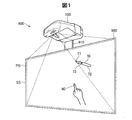
図1は、本発明の一実施形態としての位置検出システム900の斜視図である。このシステム900は、位置検出装置としてのインタラクティブプロジェクター100と、操作面を提供するスクリーン板920と、自発光指示体70とを有している。スクリーン板920の前面は、投写スクリーン面SS(projection Screen Surface)として利用される。プロジェクター100は、支持部材910によってスクリーン板920の前方かつ上方に固定されている。なお、図1では投写スクリーン面SSを鉛直に配置しているが、投写スクリーン面SSを水平に配置してこのシステム900を使用することも可能である。
FIG. 1 is a perspective view of a
プロジェクター100は、投写スクリーン面SS上に投写画面PS(Projected Screen)を投写する。投写画面PSは、通常は、プロジェクター100内で描画された画像を含んでいる。プロジェクター100内で描画された画像がない場合には、プロジェクター100から投写画面PSに光が照射されて、白色画像が表示される。本明細書において、「投写スクリーン面SS」とは、画像が投写される部材の表面を意味する。また、「投写画面PS」とは、プロジェクター100によって投写スクリーン面SS上に投写された画像の領域を意味する。通常は、投写スクリーン面SSの一部に投写画面PSが投写される。投写スクリーン面SSは、指示体による位置指示を行う操作面としても利用されるので、「操作面SS」とも呼ぶ。
The
自発光指示体70は、発光可能な先端部71と、使用者が保持する軸部72と、軸部72に設けられたボタンスイッチ73とを有するペン型の指示体である。自発光指示体70の先端部71は、例えば近赤外光を発する。自発光指示体70の構成や機能については後述する。このシステム900では、1つ又は複数の自発光指示体70とともに、1つ又は複数の非発光指示体80(非発光のペンや指など)を利用可能である。
The self-
図2Aは、位置検出システム900の正面図であり、図2Bはその側面図である。本明細書では、操作面SSの左右に沿った方向をX方向と定義し、操作面SSの上下に沿った方向をY方向と定義し、操作面SSの法線に沿った方向をZ方向と定義している。また、図2Aにおける操作面SSの左下の位置を座標(X,Y)の原点(0,0)としている。なお、便宜上、X方向を「左右方向」とも呼び、Y方向を「上下方向」とも呼び、Z方向を「前後方向」とも呼ぶ。また、Y方向(上下方向)のうち、プロジェクター100から見て投写画面PSが存在する方向を「下方向」と呼ぶ。なお、図2Bでは、図示の便宜上、スクリーン板920のうちの投写画面PSの範囲にハッチングを付している。
FIG. 2A is a front view of the
プロジェクター100は、投写画面PSを操作面SS上に投写する投写レンズ210と、投写画面PSの領域を撮像する第1カメラ310及び第2カメラ320と、指示体(自発光指示体70及び非発光指示体80)に検出光を照明するための2つの照射部411,412とを有している。検出光としては、例えば近赤外光が使用される。2台のカメラ310,320は、検出光の波長を含む波長領域の光を受光して撮像する第1の撮像機能を少なくとも有している。2台のカメラ310,320のうちの少なくとも一方は、更に、可視光を含む光を受光して撮像する第2の撮像機能を有し、これらの2つの撮像機能を切り替え可能に構成されていることが好ましい。例えば、2台のカメラ310,320は、可視光を遮断して近赤外光のみを通過させる近赤外フィルターをレンズの前に配置したりレンズの前から後退させたりすることが可能な近赤外フィルター切換機構(図示せず)をそれぞれ備えることが好ましい。図2Bに示すように、カメラ310は操作面SSからZ方向に距離Lだけ離れた位置に設置されている。
The
図2Aの例は、位置検出システム900がホワイトボードモードで動作している様子を示している。ホワイトボードモードは、自発光指示体70や非発光指示体80を用いて投写画面PS上にユーザーが任意に描画できるモードである。操作面SS上には、ツールボックスTBを含む投写画面PSが投写されている。このツールボックスTBは、処理を元に戻す取消ボタンUDBと、マウスポインターを選択するポインターボタンPTBと、描画用のペンツールを選択するペンボタンPEBと、描画された画像を消去する消しゴムツールを選択する消しゴムボタンERBと、画面を次に進めたり前に戻したりする前方/後方ボタンFRBと、を含んでいる。ユーザーは、指示体を用いてこれらのボタンをクリックすることによって、そのボタンに応じた処理を行ったり、ツールを選択したりすることが可能である。なお、システム900の起動直後は、マウスポインターがデフォールトツールとして選択されるようにしてもよい。図2Aの例では、ユーザーがペンツールを選択した後、自発光指示体70の先端部71を操作面SSに接した状態で投写画面PS内で移動させることにより、投写画面PS内に線が描画されてゆく様子が描かれている。この線の描画は、プロジェクター100の内部の投写画像生成部(後述)によって行われる。
The example of FIG. 2A shows a state where the
なお、位置検出システム900は、ホワイトボードモード以外の他のモードでも動作可能である。例えば、このシステム900は、パーソナルコンピューター(図示せず)から通信回線を介して転送されたデータの画像を投写画面PSに表示するPCインタラクティブモードでも動作可能である。PCインタラクティブモードにおいては、例えば表計算ソフトウェアなどのデータの画像が表示され、その画像内に表示された各種のツールやアイコンを利用してデータの入力、作成、修正等を行うことが可能となる。
Note that the
図3は、インタラクティブプロジェクター100と自発光指示体70の内部構成を示すブロック図である。プロジェクター100は、制御部700と、投写部200と、投写画像生成部500と、位置検出部600と、使用環境取得部800と、撮像部300と、検出光照射部410と、信号光送信部430とを有している。検出光照射部410は、第1照射部411と、第2照射部412と、調整部413とを含んでいる。使用環境取得部800は、プロジェクター100の使用環境を取得する機能を有しており、姿勢センサー810と、距離測定部820と、操作面明度測定部830とを含んでいる。
FIG. 3 is a block diagram showing an internal configuration of the
制御部700は、プロジェクター100内部の各部の制御を行う。また、制御部700は、位置検出部600で検出された指示体(自発光指示体70や非発光指示体80)によって投写画面PS上で行われた指示の内容を判定するとともに、その指示の内容に従って投写画像を作成又は変更することを投写画像生成部500に指令する。
The
投写画像生成部500は、投写画像を記憶する投写画像メモリー510を有しており、投写部200によって操作面SS上に投写される投写画像を生成する機能を有する。投写画像生成部500は、更に、投写画面PS(図2(B))の台形歪みを補正するキーストーン補正部としての機能を有することが好ましい。
The projection
投写部200は、投写画像生成部500で生成された投写画像を操作面SS上に投写する機能を有する。投写部200は、図2Bで説明した投写レンズ210の他に、光変調部220と、光源230とを有する。光変調部220は、投写画像メモリー510から与えられる投写画像データに応じて光源230からの光を変調することによって投写画像光IMLを形成する。この投写画像光IMLは、典型的には、RGBの3色の可視光を含むカラー画像光であり、投写レンズ210によって操作面SS上に投写される。なお、光源230としては、超高圧水銀ランプ等の光源ランプの他、発光ダイオードやレーザーダイオード等の種々の光源を採用可能である。また、光変調部220としては、透過型又は反射型の液晶パネルやデジタルミラーデバイス等を採用可能であり、色光別に複数の光変調部220を備えた構成としてもよい。
The
2つの照射部411,412は、指示体(自発光指示体70及び非発光指示体80)の先端部を検出するための照射検出光IDLを操作面SSとその前方の空間にわたってそれぞれ照射する。照射検出光IDLとしては、例えば近赤外光が使用される。照射部411,412は、カメラ310,320の撮像タイミングを含む所定の期間にのみ点灯し、他の期間では消灯する。また、本実施形態では、照射部411,412は、互いに重なり合わない異なる発光期間において発光するように、時分割で点灯する。なお、図2Bに示すように、第1照射部411は、第2照射部412よりも操作面SSに近い位置に配置されている。調整部413は、これらの照射部411,412の発光強度を調整することによって、撮像画像における指示体と操作面SSのコントラストを好ましい範囲に調整する。この点については更に後述する。
The two
信号光送信部430は、自発光指示体70によって受信される装置信号光ASLを送信する機能を有する。装置信号光ASLは、同期用の近赤外光信号であり、プロジェクター100の信号光送信部430から自発光指示体70に対して定期的に発せられる。自発光指示体70の先端発光部77は、装置信号光ASLに同期して、予め定められた発光パターン(発光シーケンス)を有する近赤外光である指示体信号光PSL(後述)を発する。また、撮像部300のカメラ310,320は、指示体(自発光指示体70及び非発光指示体80)の位置検出を行う際に、装置信号光ASLに同期した所定のタイミングで撮像を実行する。
The signal
撮像部300は、図2A,図2Bで説明した第1カメラ310と第2カメラ320とを有している。前述したように、2台のカメラ310,320は、検出光の波長を含む波長領域の光を受光して撮像する機能を有する。図3の例では、照射部411によって照射された照射検出光IDLが指示体(自発光指示体70及び非発光指示体80)で反射され、その反射検出光RDLが2台のカメラ310,320によって受光されて撮像される様子が描かれている。2台のカメラ310,320は、更に、自発光指示体70の先端発光部77から発せられる近赤外光である指示体信号光PSLも受光して撮像する。2台のカメラ310,320の撮像は、検出光照射部410から発せられる照射検出光IDLがオン状態(発光状態)である第1の期間と、照射検出光IDLがオフ状態(非発光状態)である第2の期間と、の両方で実行される。位置検出部600は、これらの2種類の期間における画像を比較することによって、画像内に含まれる個々の指示体が、自発光指示体70と非発光指示体80のいずれであるかを判定することが可能である。
The
なお、2台のカメラ310,320の少なくとも一方は、近赤外光を含む光を用いて撮像する機能に加えて、可視光を含む光を用いて撮像する機能を有することが好ましい。こうすれば、操作面SS上に投写された投写画面PSをそのカメラで撮像し、その画像を利用して投写画像生成部500がキーストーン補正を実行することが可能である。1台以上のカメラを利用したキーストーン補正の方法は周知なので、ここではその説明は省略する。
Note that at least one of the two
位置検出部600は、2台のカメラ310,320で撮像された画像を用い、三角測量を利用して指示体(自発光指示体70や非発光指示体80)の先端部の三次元位置を決定する機能を有する。この際、位置検出部600は、自発光指示体70の発光パターンを利用して、画像内の個々の指示体が自発光指示体70と非発光指示体80のいずれであるかについても判定する。本実施形態において、位置検出部600は、検出部610と、コントラスト測定部620とを有している。検出部610は、カメラ310,320で撮像された撮像画像を解析して指示体の指示位置を検出する機能を有する。コントラスト測定部620は、カメラ310,320で撮像された撮像画像におけるコントラストを測定する機能を有する。こうして得られるコントラストは、2つの照射部411,412の発光強度の調整(後述)に使用される。
The
使用環境取得部800は、プロジェクター100の使用環境を取得する機能を有する。本実施形態では、プロジェクター100の使用環境として、以下を利用可能である。
(a)プロジェクター100の設置姿勢
(b)プロジェクター100と操作面SSの間の距離
(c)環境光下の操作面SSの明るさ
The use
(A) Installation posture of projector 100 (b) Distance between
姿勢センサー810は、プロジェクター100の設置姿勢を検出するためのセンサーである。姿勢センサー810は、プロジェクター100が水平姿勢(操作面SSが鉛直)か垂直姿勢(操作面SSが水平)かを検出可能に構成されていることが好ましい。姿勢センサー810としては、例えばジャイロを使用可能である。
The
距離測定部820は、プロジェクター100と操作面SSの間の距離を測定する。例えば、距離測定部820は、図2Bに示したカメラ310と操作面SSの距離Lを、プロジェクター100と操作面SSの間の代表的な距離として測定可能である。この距離Lは、例えば予め準備された基準パターン画像を操作面SSに投写して2台のカメラ310,320でそれぞれ撮像し、それらの撮像画像を用いた三角測量を用いて測定可能である。或いは、基準パターン画像を1つのカメラ310で撮像し、その撮像画像と投写画像メモリー510内の基準パターン画像とを用いた三角測量を実行することによっても距離Lを測定できる。なお、本実施形態において、距離Lは、プロジェクター100と操作面SSの間の代表的な距離として使用されており、カメラ310以外の他の代表点と操作面SSとの距離を測定してもよい。
Distance measuring
操作面明度測定部830は、環境光下の操作面SSの明るさを測定する。例えば、操作面明度測定部830は、投写部200と検出光照射部410のいずれからも光を操作面SS上に投写しない状態(バックグラウンド状態)において、操作面SSの明るさを測定する。この操作面SSの明るさも、2つの照射部411,412の発光強度の調整(後述)に利用可能である。
The operation surface
自発光指示体70には、ボタンスイッチ73の他に、信号光受信部74と、制御部75と、先端スイッチ76と、先端発光部77とが設けられている。信号光受信部74は、プロジェクター100の信号光送信部430から発せられた装置信号光ASLを受信する機能を有する。先端スイッチ76は、自発光指示体70の先端部71が押されるとオン状態になり、先端部71が解放されるとオフ状態になるスイッチである。先端スイッチ76は、通常はオフ状態にあり、自発光指示体70の先端部71が操作面SSに接触するとその接触圧によってオン状態になる。先端スイッチ76がオフ状態のときには、制御部75は、先端スイッチ76がオフ状態であることを示す特定の第1の発光パターンで先端発光部77を発光させることによって、第1の発光パターンを有する指示体信号光PSLを発する。一方、先端スイッチ76がオン状態になると、制御部75は、先端スイッチ76がオン状態であることを示す特定の第2の発光パターンで先端発光部77を発光させることによって、第2の発光パターンを有する指示体信号光PSLを発する。これらの第1の発光パターンと第2の発光パターンは、互いに異なるので、位置検出部600は、2台のカメラ310,320で撮像された画像を分析することによって、先端スイッチ76がオン状態かオフ状態かを識別することが可能である。
In addition to the
上述のように、本実施形態では、自発光指示体70の先端部71が操作面SSに接しているか否かの接触判定を、先端スイッチ76のオン/オフに応じて行っている。ところで、自発光指示体70の先端部71の三次元位置は、2台のカメラ310,320で撮像された画像を用いた三角測量によって求めることができるので、この三次元位置を用いて自発光指示体70の先端部71の接触判定を実行することも可能である。但し、三角測量によるZ座標(操作面SSの法線方向の座標)の検出精度は、必ずしも高くない場合がある。従って、先端スイッチ76のオン/オフに応じて接触判定を行うようにすれば、接触判定をより精度良く実行できる点で好ましい。
As described above, in the present embodiment, the contact determination as to whether or not the
自発光指示体70のボタンスイッチ73は、先端スイッチ76と同じ機能を有する。従って、制御部75は、ユーザーによってボタンスイッチ73が押された状態では上記第2の発光パターンで先端発光部77を発光させ、ボタンスイッチ73が押されていない状態では上記第1の発光パターンで先端発光部77を発光させる。換言すれば、制御部75は、先端スイッチ76とボタンスイッチ73の少なくとも一方がオンの状態では上記第2の発光パターンで先端発光部77を発光させ、先端スイッチ76とボタンスイッチ73の両方がオフの状態では上記第1の発光パターンで先端発光部77を発光させる。
The
但し、ボタンスイッチ73に対して先端スイッチ76と異なる機能を割り当てるようにしてもよい。例えば、ボタンスイッチ73に対してマウスの右クリックボタンと同じ機能を割り当てた場合には、ユーザーがボタンスイッチ73を押すと、右クリックの指示がプロジェクター100の制御部700に伝達され、その指示に応じた処理が実行される。このように、ボタンスイッチ73に対して先端スイッチ76と異なる機能を割り当てた場合には、先端発光部77は、先端スイッチ76のオン/オフ状態及びボタンスイッチ73のオン/オフ状態に応じて、互いに異なる4つの発光パターンで発光する。この場合には、自発光指示体70は、先端スイッチ76とボタンスイッチ73のオン/オフ状態の4つの組み合わせを区別しつつ、プロジェクター100に伝達することが可能である。
However, a function different from that of the
図3に描かれている5種類の信号光の具体例をまとめると以下の通りである。
(1)投写画像光IML:操作面SSに投写画面PSを投写するために、投写レンズ210によって操作面SS上に投写される画像光(可視光)である。
(2)照射検出光IDL: 指示体(自発光指示体70及び非発光指示体80)の先端部を検出するために、検出光照射部410(411,412)によって操作面SSとその前方の空間にわたって照射される近赤外光である。
(3)反射検出光RDL:照射検出光IDLとして照射された近赤外光のうち、指示体(自発光指示体70及び非発光指示体80)によって反射され、2台のカメラ310,320によって受光される近赤外光である。
(4)装置信号光ASL:プロジェクター100と自発光指示体70との同期をとるために、プロジェクター100の信号光送信部430から定期的に発せられる近赤外光である。
(5)指示体信号光PSL:装置信号光ASLに同期したタイミングで、自発光指示体70の先端発光部77から発せられる近赤外光である。指示体信号光PSLの発光パターンは、自発光指示体70のスイッチ73,76のオン/オフ状態に応じて変更される。また、複数の自発光指示体70を識別する固有の発光パターンを有する。
Specific examples of the five types of signal light depicted in FIG. 3 are as follows.
(1) Projected image light IML: Image light (visible light) projected on the operation surface SS by the
(2) Irradiation detection light IDL: The detection surface irradiating unit 410 (411, 412) detects the front end of the indicator (the self-
(3) Reflection detection light RDL: Of the near-infrared light irradiated as irradiation detection light IDL, it is reflected by a pointer (self-
(4) Device signal light ASL: Near-infrared light periodically emitted from the signal
(5) Indicator signal light PSL: Near-infrared light emitted from the tip
図4は、検出光強度の調整前のコントラストの例を示す説明図である。図4の横軸は、操作面SS上の位置を示している。実際には、操作面SS上の位置は2次元であるが、図4では図示の便宜上、一次元で表現している。縦軸は指示体(特に非発光指示体80)と操作面SSのコントラストの値を示す。コントラストは、撮像画像における操作面SSの画素値に対する指示体の画素値の比である。このコントラストは、例えば、指示体の先端を含む一定サイズの領域(例えば20×20画素)の中の操作面SSの画素値の平均と指示体の画素値の平均との比として算出することができる。縦軸の上半分は、ポジティブコントラストの範囲であり、下半分はネガティブコントラストの範囲である。「ポジティブコントラスト」は、撮像画像において指示体が操作面SSよりも明るい状態を意味しており、「ネガティブコントラスト」は、指示体が操作面SSよりも暗い状態を意味している。ポジティブコントラスト閾値PCtは、コントラストがこの閾値PCt以上の場合に指示体を操作面SSと区別して明瞭に認識し得る閾値である。ネガティブコントラスト閾値NCtは、コントラストがこの閾値NCt以下の場合に指示体を操作面SSと区別して明瞭に認識し得る閾値である。 FIG. 4 is an explanatory diagram illustrating an example of the contrast before the detection light intensity is adjusted. The horizontal axis in FIG. 4 indicates a position on the operation surface SS. Actually, the position on the operation surface SS is two-dimensional, but in FIG. 4, it is expressed in one-dimensional for convenience of illustration. The vertical axis indicates the contrast value between the indicator (particularly, the non-light emitting indicator 80) and the operation surface SS. The contrast is a ratio of the pixel value of the pointer to the pixel value of the operation surface SS in the captured image. This contrast can be calculated, for example, as a ratio between the average of the pixel values of the operation surface SS and the average of the pixel values of the pointer in a region of a fixed size (for example, 20 × 20 pixels) including the tip of the pointer. it can. The upper half of the vertical axis is the range of the positive contrast, and the lower half is the range of the negative contrast. “Positive contrast” means a state where the pointer is brighter than the operation surface SS in the captured image, and “negative contrast” means a state where the pointer is darker than the operation surface SS. The positive contrast threshold value PCt is a threshold value that allows the pointer to be clearly recognized in distinction from the operation surface SS when the contrast is equal to or greater than the threshold value PCt. The negative contrast threshold value NCt is a threshold value at which the indicator can be clearly recognized in distinction from the operation surface SS when the contrast is equal to or less than the threshold value NCt.
図4には、2つのコントラストCV1,CV2の分布が実線で描かれている。第1コントラストCV1は、第2照射部412が発光せずに第1照射部411のみが発光した状態で撮像された撮像画像におけるコントラストである。一方、第2コントラストCV2は、第1照射部411が発光せずに第2照射部412のみが発光した状態で撮像された撮像画像におけるコントラストである。ここでは、第1照射部411と第2照射部412の発光強度(検出光強度)は同じものと仮定している。これらのコントラストCV1,CV2は、カメラ310(又は320)で撮像して得られた撮像画像を用いて、コントラスト測定部620が算出したものである。操作面SSのほぼ全体に亘るコントラストCV1,CV2の分布は、例えば、2つの照射部411,412を時分割で点灯させている状態で、非発光指示体80の先端を操作面SS上で移動させつつカメラ310を用いて複数の位置で撮像を行い、得られた複数の撮像画像を解析することによって求めることができる。
In FIG. 4, the distributions of the two contrasts CV1 and CV2 are drawn by solid lines. The first contrast CV1 is a contrast in a captured image captured in a state where only the
この例では、第1コントラストCV1は、操作面SS上のすべての位置において、2つの閾値PCt,NCtの間にある。従って、第1照射部411を用いた場合には、指示体と操作面SSのコントラストが不十分であり、検出部610が撮像画像から指示体を明瞭に認識することができない可能性がある。一方、第2コントラストCV2は、操作面SS上の一部の領域R21では2つの閾値PCt,NCtの間にあり、その他の領域R22ではネガティブコントラスト閾値NCt以下となっている。従って、第2照射部412を用いた場合には、領域R22では撮像画像から指示体を明瞭に認識することができるが、領域R21では指示体を明瞭に認識できない可能性がある。検出光照射部410の調整部413は、これらのコントラストCV1,CV2の測定結果に応じて、2つの照射部411,412の少なくとも一方の検出光強度を調整することによって、操作面SS上の任意の位置において、コントラストが2つの閾値PCt,NCtのいずれかを超えるように調整することが可能である。なお、本明細書において、「コントラストが閾値を超える」という語句は、コントラストがポジティブコントラスト閾値PCt以上となるか又はネガティブコントラスト閾値NCt以下となること、を意味する。
In this example, the first contrast CV1 is between the two thresholds PCt and NCt at all positions on the operation surface SS. Therefore, when the
図5は、検出光強度の調整後のコントラストの例を示す説明図である。ここでは、第1照射部411の検出光強度を高めることによって、第1コントラストCV1を図4に比べて増大させている。この調整の結果、第1コントラストCV1は、操作面SS上の領域R11ではポジティブコントラスト閾値PCt以上となり、その他の領域R12では2つの閾値PCt,NCtの間の値を取る。従って、第1照射部411を用いた場合には、領域R11において撮像画像から指示体を明瞭に認識することが可能となる。また、第1照射部411の発光時に得られるコントラストCV1が閾値PCtを超える領域R11と、第2照射部412の発光時に得られるコントラストCV2が閾値NCtを超える領域R22との和が、操作面SSの全領域を包含している。言い換えれば、操作面SS上のすべての位置が領域R11または領域R22に属している。このようなコントラストCV1,CV2が得られる場合には、操作面SS上の任意の位置において、指示体(特に指示体の先端)を操作面SSと区別して明瞭に識別することが可能となる。実際には、操作面SSが、プロジェクター100から画像が投写される領域である投写画面PS(図2B)よりもやや広い場合が多い。この場合には、第1照射部411の発光時に得られるコントラストCV1が閾値PCtを超える領域R11と、第2照射部412の発光時に得られるコントラストCV2が閾値NCtを超える領域R22との和が、少なくとも投写画面PSの全領域を包含することが好ましい。
FIG. 5 is an explanatory diagram illustrating an example of the contrast after adjusting the detection light intensity. Here, the first contrast CV1 is increased as compared with FIG. 4 by increasing the detection light intensity of the
なお、図5の例では、第1照射部411の発光強度を高めていたが、第2照射部412の発光強度を弱めるようにしても良い。また、場合によっては、第1照射部411の発光強度を弱めたり、第2照射部412の発光強度を強めたりすることによって好ましいコントラストが得られる場合もある。この説明から理解できるように、2つの照射部411,412の少なくとも一方を調整することによって、指示体と操作面SSのコントラストが閾値PCt、NCtを超えるように調整することが可能である。
In the example of FIG. 5, the light emission intensity of the
通常の場合には、2つの照射部411,412のうち、操作面SSにより近い第1照射部411の発光強度を、より遠い第2照射部412の発光強度よりも高めることによって、図5のような好ましいコントラストCV1,CV2が得られる。従って、実験的又は経験的に、操作面SSにより近い第1照射部411の発光強度を、操作面SSからより遠い第2照射部412の発光強度よりも十分に高く設定しておくことによって、好ましいコントラストが得られるようにしても良い。但し、上述したように、撮像部300で撮像した撮像画像を解析して得られたコントラストを用いて照射部411,412の発光強度を調整するようにすれば、実際の設置環境に応じて適切な調整を行うことが可能である。
In the normal case, of the two
なお、2つの照射部411,412は、互いに重なり合わない異なる発光期間に発光するように、時分割で発光することが好ましい。2つの照射部411,412を時分割で発光させるようにすれば、図5の例のように、それぞれの発光期間で得られるコントラストにおいて、その正負が逆転している領域が操作面SS上に存在していても、異なる発光期間における撮像画像を利用すれば、いずれの領域においても十分なコントラストを容易に得ることができる。但し、2つの照射部411,412を同時に発光させても良い。この場合にも、2つの照射部411,412の少なくとも一方の発光強度を調整することによって、操作面SSの任意の位置においてコントラストが閾値を超えるようにすることが好ましい。
It is preferable that the two
検出光照射部410の調整部413は、更に、撮像部300で撮像した撮像画像を解析して得られたコントラストと共に、使用環境取得部800で取得されるプロジェクター100の使用環境を利用して、照射部411,412の発光強度を調整するようにしてもよい。使用環境を利用した発光強度の調整は、例えば、以下のように実行できる。
The
(a)プロジェクター100の設置姿勢を用いた発光強度の調整
姿勢センサー810は、プロジェクター100の設置姿勢(水平姿勢か垂直姿勢か)を検出可能である。プロジェクター100の設置姿勢は、操作面SS上の環境光の強さに影響を与え得るので、コントラストにもかなり大きな影響がある可能性がある。そこで、調整部413は、例えば、プロジェクター100が水平姿勢である場合よりも垂直姿勢である場合の方が、第1照射部411の発光強度(又は第1照射部411と第2照射部412の発光強度の比)が高くなるように調整してもよい。こうすれば、より好ましいコントラストを得ることが可能である。
(A) Adjustment of Light Emission Intensity Using Installation Position of
(b)プロジェクター100と操作面SSの間の距離Lを用いた発光強度の調整
距離測定部820は、プロジェクター100と操作面SSの間の距離L(図2B)を測定可能である。調整部413は、この距離Lが遠いほど、第1照射部411の発光強度(又は第1照射部411と第2照射部412の発光強度の比)が高くなるように調整することによって、より好ましいコントラストを得るようにしてもよい。なお、プロジェクター100と操作面SSの間の距離Lは、投写画面PSの大きさ(すなわち投写サイズ)と等価である。
(B) Adjustment of Light Emission Intensity Using Distance L Between
(c)環境光下の操作面SSの明るさを用いた発光強度の調整
操作面明度測定部830は、投写部200と検出光照射部410から光を操作面SS上に投写せず、環境光のみの状態における操作面SSの明るさを測定可能である。調整部413は、この状態における操作面SSが明るいほど第1照射部411の発光強度(又は第1照射部411と第2照射部412の発光強度の比)が高くなるように調整することによって、より好ましいコントラストを得るようにしてもよい。
(C) Adjusting Light Emission Intensity Using Brightness of Operation Surface SS Under Ambient Light The operation surface
なお、2つのカメラ310,320で撮像した2つの撮影画像に関して、コントラストCV1,CV2の分布が同様の傾向を示す場合と大幅に異なる場合とが発生しうる。後者の場合には、2つのカメラ310,320が撮像した2つの撮像画像のそれぞれについて、操作面SS上の任意の位置において指示体を明瞭に認識し得るように、2つの照射部411,412の発光強度を調整することが好ましい。
In addition, regarding two captured images captured by the two
以上のように、上記実施形態では、調整部413は、2つの照射部411,412の少なくとも一方の発光強度を調整することによって、撮像画像における指示体と操作面SSのコントラストが閾値PCt,NCtを超えるように調整する。この結果、操作面SSの任意の位置において、操作面SSから指示体(自発光指示体70や非発光指示体80)を明瞭に識別することが可能である。
As described above, in the above-described embodiment, the
・変形例:
なお、この発明は上記の実施例や実施形態に限られるものではなく、その要旨を逸脱しない範囲において種々の態様において実施することが可能であり、例えば次のような変形も可能である。
・ Modification:
The present invention is not limited to the above-described examples and embodiments, but can be implemented in various modes without departing from the gist of the invention, and for example, the following modifications are possible.
・変形例1:
上記実施形態では、検出光照射部410が2つの照射部411,412を有する例を説明したが、本発明は、1つの照射部のみを有する位置検出装置やプロジェクターにも適用可能である。この場合にも、調整部413が1つの照射部の発光強度を調整することによって、指示体と操作面SSのコントラストが閾値を超えるようにすることが好ましい。なお、1つの照射部の1回の発光では、操作面SSの任意の位置においてコントラストが閾値を超えるように調整を行えない場合も考えられる。この場合には、1つの照射部を複数の発光期間で互いに異なる発光強度で発光させるとともに、それらの複数の発光期間でそれぞれ撮像して得られる複数の撮像画像を使用して、操作面SSの任意の位置においてコントラストが閾値を超えるように調整を行うことが好ましい。このような調整は、複数の照射部を同じタイミングで点灯させる場合にも適用可能である。
-Modification 1
In the above-described embodiment, the example in which the detection
・変形例2:
上記実施形態では、ステレオカメラ方式(三角測量)で指示体の指示位置を検出するインタラクティブプロジェクターを説明したが、本発明は、他のタイプのインタラクティブプロジェクターにも適用可能である。例えば、上述した特許文献1に記載されているような層状検出光を照射する照射部(ライトカーテンユニット)を利用したインタラクティブプロジェクターにも本発明を適用可能である。
-Modified example 2:
In the above embodiment, the interactive projector that detects the pointing position of the pointer using the stereo camera method (triangulation) has been described. However, the present invention is applicable to other types of interactive projectors. For example, the present invention can be applied to an interactive projector using an irradiation unit (light curtain unit) that irradiates the layered detection light as described in Patent Document 1 described above.
・変形例3:
上記実施形態では、位置検出装置の一例としてインタラクティブプロジェクターを説明したが、本発明は、インタラクティブプロジェクター以外の他の位置検出装置にも適用可能である。例えば、自発光指示体を用いて操作面上の位置を指示するデジタイザやタブレットにも本発明を適用可能である。
-Modified example 3:
In the above embodiment, the interactive projector has been described as an example of the position detecting device. However, the present invention can be applied to other position detecting devices other than the interactive projector. For example, the present invention is applicable to a digitizer or a tablet that indicates a position on an operation surface using a self-luminous indicator.
以上、いくつかの実施例に基づいて本発明の実施の形態について説明してきたが、上記した発明の実施の形態は、本発明の理解を容易にするためのものであり、本発明を限定するものではない。本発明は、その趣旨並びに特許請求の範囲を逸脱することなく、変更、改良され得るとともに、本発明にはその等価物が含まれることはもちろんである。 As described above, the embodiments of the present invention have been described based on some examples. However, the above embodiments of the present invention are for facilitating understanding of the present invention, and limit the present invention. Not something. The present invention can be modified and improved without departing from the spirit and scope of the claims, and it is needless to say that the present invention includes equivalents thereof.
70…自発光指示体、71…先端部、72…軸部、73…ボタンスイッチ、74…信号光受信部、75…制御部、76…先端スイッチ、77…先端発光部、80…非発光指示体、100…インタラクティブプロジェクター、200…投写部、210…投写レンズ、220…光変調部、230…光源、300…撮像部、310,320…カメラ、410…検出光照射部、411…第1照射部、412…第2照射部、413…調整部、430…信号光送信部、500…投写画像生成部、510…投写画像メモリー、600…位置検出部、610…検出部、620…コントラスト測定部、700…制御部、800…使用環境取得部、810…姿勢センサー、820…距離測定部、830…操作面明度測定部、900…位置検出システム、910…支持部材、920…スクリーン板、ASL…装置信号光、CV1…第1コントラスト、CV2…第2コントラスト、ERB…消しゴムボタン、FRB…前方/後方ボタン、IDL…照射検出光、IML…投写画像光、L…距離、NCt…ネガティブコントラスト閾値、PCt…ポジティブコントラスト閾値、PEB…ペンボタン、PS…投写画面、PSL…指示体信号光、PTB…ポインターボタン、R11,R12,R21,R22…投写面SS上の領域、RDL…反射検出光、SS…操作面(投写スクリーン面)、TB…ツールボックス、UDB…取消ボタン 70: self-luminous indicator, 71: tip, 72: shaft, 73: button switch, 74: signal light receiving unit, 75: control unit, 76: tip switch, 77: tip light emitting unit, 80: non-light emitting instruction Body, 100 interactive projector, 200 projection unit, 210 projection lens, 220 light modulation unit, 230 light source, 300 imaging unit, 310, 320 camera, 410 detection light irradiation unit, 411 first irradiation Unit, 412: second irradiation unit, 413: adjustment unit, 430: signal light transmission unit, 500: projection image generation unit, 510: projection image memory, 600: position detection unit, 610: detection unit, 620: contrast measurement unit , 700: control unit, 800: use environment acquisition unit, 810: attitude sensor, 820: distance measurement unit, 830: operation surface brightness measurement unit, 900: position detection system, 910: support Member, 920: screen plate, ASL: device signal light, CV1: first contrast, CV2: second contrast, ERB: eraser button, FRB: front / rear button, IDL: irradiation detection light, IML: projection image light, L ... Distance, NCt ... Negative contrast threshold, PCt ... Positive contrast threshold, PEB ... Pen button, PS ... Projection screen, PSL ... Indicator signal light, PTB ... Pointer button, R11, R12, R21, R22 ... On the projection surface SS Area, RDL: Reflection detection light, SS: Operation surface (projection screen surface), TB: Tool box, UDB: Cancel button
Claims (12)
前記操作面に検出光を照射する第1照射部及び第2照射部と、
前記操作面を撮像する撮像部と、
前記撮像部で撮像された撮像画像に基づいて、前記指示体により指示された指示位置を検出する検出部と、
を備え、
前記第1照射部は、前記第2照射部よりも前記操作面に近い側に配置され、前記第2照射部よりも発光強度が強く、
前記第1照射部及び前記第2照射部の発光強度は、前記第1照射部の発光時に得られる第1コントラストが閾値を超える第1領域と、前記第2照射部の発光時に得られる第2コントラストが閾値を超える第2領域との和が、前記操作面の全領域を包含するように調整されている、位置検出装置。 A position detection device that detects a designated position designated by a pointer on an operation surface,
A first irradiator and a second irradiator that irradiate the operation surface with detection light;
An imaging unit for imaging the operation surface;
Based on a captured image captured by the imaging unit, a detection unit that detects a designated position designated by the indicator,
With
The first irradiation unit, than said second irradiation section is disposed closer to the operation surface, strongly luminous intensity than the second illumination unit,
The luminous intensities of the first irradiating unit and the second irradiating unit include a first region in which a first contrast obtained when the first irradiating unit emits light exceeds a threshold, and a second region obtained when the second irradiating unit emits light. The position detecting device , wherein a sum of the second area having a contrast exceeding a threshold value is adjusted to include the entire area of the operation surface .
前記操作面に検出光を照射する第1照射部及び第2照射部と、
前記操作面を撮像する撮像部と、
前記撮像部で撮像された撮像画像に基づいて、前記指示体により指示された指示位置を検出する検出部と、
前記第1照射部及び前記第2照射部の少なくとも一方の発光強度を調整することによって、前記撮像画像における前記指示体と前記操作面との間のコントラストが閾値を超えるように調整する調整部と、
を備え、
前記第1照射部及び前記第2照射部の発光強度は、前記第1照射部の発光時に得られる第1コントラストが閾値を超える第1領域と、前記第2照射部の発光時に得られる第2コントラストが閾値を超える第2領域との和が、前記操作面の全領域を包含するように調整される、位置検出装置。 A position detection device that detects a designated position designated by a pointer on an operation surface,
A first irradiator and a second irradiator that irradiate the operation surface with detection light;
An imaging unit for imaging the operation surface;
Based on a captured image captured by the imaging unit, a detection unit that detects a designated position designated by the indicator,
An adjustment unit that adjusts the contrast between the indicator and the operation surface in the captured image to exceed a threshold value by adjusting the emission intensity of at least one of the first irradiation unit and the second irradiation unit; ,
Equipped with a,
The luminous intensities of the first irradiating unit and the second irradiating unit include a first region in which a first contrast obtained when the first irradiating unit emits light exceeds a threshold, and a second region obtained when the second irradiating unit emits light. A position detection device , wherein a sum of a second area having a contrast exceeding a threshold value is adjusted to include the entire area of the operation surface .
前記位置検出装置の使用環境を取得する使用環境取得部を備え、
前記調整部は、前記位置検出装置の使用環境に応じて前記発光強度の調整を行う、位置検出装置。 The position detecting device according to claim 2, further comprising:
A use environment acquisition unit that acquires a use environment of the position detection device,
The position detection device, wherein the adjustment unit adjusts the light emission intensity according to a use environment of the position detection device.
前記使用環境は、前記位置検出装置の設置姿勢と、前記位置検出装置と前記操作面の間の距離と、環境光下の前記操作面の明るさと、のうちの少なくとも1つを含む、位置検出装置。 The position detection device according to claim 3,
The use environment includes at least one of an installation posture of the position detection device, a distance between the position detection device and the operation surface, and brightness of the operation surface under ambient light. apparatus.
前記第1照射部は、前記第2照射部よりも前記操作面に近い側に配置され、
前記調整部は、前記第1照射部の発光強度が前記第2照射部よりも強くなるように調整する、位置検出装置。 The position detection device according to any one of claims 2 to 4,
The first irradiation unit is disposed closer to the operation surface than the second irradiation unit,
The position detection device, wherein the adjustment unit adjusts the emission intensity of the first irradiation unit to be higher than that of the second irradiation unit.
前記第1照射部及び前記第2照射部は、時分割で前記検出光を照射し、
前記撮像部は、前記第1照射部の発光期間と前記第2照射部の発光期間のそれぞれにおいて撮像を行う、位置検出装置。 The position detection device according to any one of claims 1 to 5,
The first irradiator and the second irradiator irradiate the detection light in a time-division manner,
The position detection device, wherein the imaging unit performs imaging in each of a light emission period of the first irradiation unit and a light emission period of the second irradiation unit.
前記操作面上に画像を投写する投写部を備える、位置検出装置。 The position detecting device according to any one of claims 1 to 6 , further comprising:
A position detection device comprising a projection unit for projecting an image on the operation surface.
前記操作面に検出光を照射する第1照射部及び第2照射部と、
前記操作面を撮像する撮像部と、
前記撮像部で撮像された撮像画像に基づいて、前記指示体により指示された指示位置を検出する検出部と、
前記位置検出装置の使用環境を取得する使用環境取得部と、
前記位置検出装置の使用環境に応じて前記第1照射部及び前記第2照射部の少なくとも一方の発光強度を調整することによって、前記撮像画像における前記指示体と前記操作面との間のコントラストが閾値を超えるように調整する調整部と、
を備える位置検出装置。 A position detection device that detects a designated position designated by a pointer on an operation surface,
A first irradiator and a second irradiator that irradiate the operation surface with detection light;
An imaging unit for imaging the operation surface;
Based on a captured image captured by the imaging unit, a detection unit that detects a designated position designated by the indicator,
A use environment acquisition unit that acquires a use environment of the position detection device,
By adjusting the light emission intensity of at least one of the first irradiation unit and the second irradiation unit according to the use environment of the position detection device, the contrast between the pointer and the operation surface in the captured image is reduced. An adjusting unit that adjusts to exceed the threshold value;
A position detecting device comprising:
前記操作面に検出光を照射する第1照射部及び第2照射部と、
前記操作面を撮像する撮像部と、
前記撮像部で撮像された撮像画像に基づいて、前記指示体により指示された指示位置を検出する検出部と、
前記第1照射部及び前記第2照射部の少なくとも一方の発光強度を調整することによって、前記撮像画像における前記指示体と前記操作面との間のコントラストが閾値を超えるように調整する調整部と、
を備え、
前記第1照射部は、前記第2照射部よりも前記操作面に近い側に配置され、
前記調整部は、前記第1照射部の発光強度が前記第2照射部よりも強くなるように調整する、位置検出装置。 A position detection device that detects a designated position designated by a pointer on an operation surface,
A first irradiator and a second irradiator that irradiate the operation surface with detection light;
An imaging unit for imaging the operation surface;
Based on a captured image captured by the imaging unit, a detection unit that detects a designated position designated by the indicator,
An adjustment unit that adjusts the contrast between the indicator and the operation surface in the captured image to exceed a threshold value by adjusting the emission intensity of at least one of the first irradiation unit and the second irradiation unit; ,
Equipped with a,
The first irradiation unit is disposed closer to the operation surface than the second irradiation unit,
The position detection device , wherein the adjustment unit adjusts the emission intensity of the first irradiation unit to be higher than that of the second irradiation unit .
(a)第1照射部及び第2照射部を用いて前記操作面に検出光を照射する工程と、
(b)前記操作面を撮像する工程と、
(c)前記工程(b)で撮像された撮像画像に基づいて、前記指示体により指示された指示位置を検出する工程と、
(d)前記第1照射部及び前記第2照射部の少なくとも一方の発光強度を調整することによって、前記撮像画像における前記指示体と前記操作面との間のコントラストが閾値を超えるように調整する工程と、
を備え、
前記第1照射部及び前記第2照射部の発光強度は、前記第1照射部の発光時に得られる第1コントラストが閾値を超える第1領域と、前記第2照射部の発光時に得られる第2コントラストが閾値を超える第2領域との和が、前記操作面の全領域を包含するように調整される、コントラスト調整方法。 A contrast adjustment method for a position detection device that detects a designated position designated by a pointer on an operation surface,
(A) irradiating the operation surface with detection light using a first irradiation unit and a second irradiation unit;
(B) imaging the operation surface;
(C) detecting a designated position designated by the pointer based on the image captured in the step (b);
(D) adjusting the light emission intensity of at least one of the first irradiation unit and the second irradiation unit so that the contrast between the pointer and the operation surface in the captured image exceeds a threshold value. Process and
With
The luminous intensities of the first irradiating unit and the second irradiating unit include a first region in which a first contrast obtained when the first irradiating unit emits light exceeds a threshold, and a second region obtained when the second irradiating unit emits light. A contrast adjustment method , wherein a sum of a second area having a contrast exceeding a threshold value is adjusted to include the entire area of the operation surface .
(a)第1照射部及び第2照射部を用いて前記操作面に検出光を照射する工程と、
(b)前記操作面を撮像する工程と、
(c)前記工程(b)で撮像された撮像画像に基づいて、前記指示体により指示された指示位置を検出する工程と、
(d)前記位置検出装置の使用環境を取得する工程と、
(e)前記位置検出装置の使用環境に応じて前記第1照射部及び前記第2照射部の少なくとも一方の発光強度を調整することによって、前記撮像画像における前記指示体と前記操作面との間のコントラストが閾値を超えるように調整する工程と、
を備えるコントラスト調整方法。 A contrast adjustment method for a position detection device that detects a designated position designated by a pointer on an operation surface,
(A) irradiating the operation surface with detection light using a first irradiation unit and a second irradiation unit;
(B) imaging the operation surface;
(C) detecting a designated position designated by the pointer based on the image captured in the step (b);
(D) acquiring a use environment of the position detection device;
( E ) adjusting the light emission intensity of at least one of the first irradiating unit and the second irradiating unit in accordance with the use environment of the position detecting device, so that the distance between the pointer and the operation surface in the captured image is adjusted; Adjusting the contrast so as to exceed a threshold value;
A contrast adjustment method comprising:
(a)第1照射部及び第2照射部を用いて前記操作面に検出光を照射する工程と、
(b)前記操作面を撮像する工程と、
(c)前記工程(b)で撮像された撮像画像に基づいて、前記指示体により指示された指示位置を検出する工程と、
(d)前記第1照射部及び前記第2照射部の少なくとも一方の発光強度を調整することによって、前記撮像画像における前記指示体と前記操作面との間のコントラストが閾値を超えるように調整する工程と、
を備え、
前記第1照射部は、前記第2照射部よりも前記操作面に近い側に配置され、
前記工程(d)は、前記第1照射部の発光強度が前記第2照射部よりも強くなるように調整する、コントラスト調整方法。 A contrast adjustment method for a position detection device that detects a designated position designated by a pointer on an operation surface,
(A) irradiating the operation surface with detection light using a first irradiation unit and a second irradiation unit;
(B) imaging the operation surface;
(C) detecting a designated position designated by the pointer based on the image captured in the step (b);
(D) adjusting the light emission intensity of at least one of the first irradiation unit and the second irradiation unit so that the contrast between the pointer and the operation surface in the captured image exceeds a threshold value. Process and
Equipped with a,
The first irradiation unit is disposed closer to the operation surface than the second irradiation unit,
The step (d) is a contrast adjustment method of adjusting the emission intensity of the first irradiation unit to be higher than that of the second irradiation unit .
Priority Applications (3)
| Application Number | Priority Date | Filing Date | Title |
|---|---|---|---|
| JP2016027490A JP6623812B2 (en) | 2016-02-17 | 2016-02-17 | Position detecting device and contrast adjusting method thereof |
| CN201710063072.4A CN107094247B (en) | 2016-02-17 | 2017-02-03 | Position detection device and contrast adjustment method thereof |
| US15/425,792 US10321106B2 (en) | 2016-02-17 | 2017-02-06 | Position detection apparatus and contrast adjustment method used with the same |
Applications Claiming Priority (1)
| Application Number | Priority Date | Filing Date | Title |
|---|---|---|---|
| JP2016027490A JP6623812B2 (en) | 2016-02-17 | 2016-02-17 | Position detecting device and contrast adjusting method thereof |
Publications (3)
| Publication Number | Publication Date |
|---|---|
| JP2017146753A JP2017146753A (en) | 2017-08-24 |
| JP2017146753A5 JP2017146753A5 (en) | 2019-02-28 |
| JP6623812B2 true JP6623812B2 (en) | 2019-12-25 |
Family
ID=59562350
Family Applications (1)
| Application Number | Title | Priority Date | Filing Date |
|---|---|---|---|
| JP2016027490A Active JP6623812B2 (en) | 2016-02-17 | 2016-02-17 | Position detecting device and contrast adjusting method thereof |
Country Status (3)
| Country | Link |
|---|---|
| US (1) | US10321106B2 (en) |
| JP (1) | JP6623812B2 (en) |
| CN (1) | CN107094247B (en) |
Families Citing this family (11)
| Publication number | Priority date | Publication date | Assignee | Title |
|---|---|---|---|---|
| TW201102068A (en) * | 2009-06-02 | 2011-01-16 | Novartis Ag | Treatment of ophthalmologic disorders mediated by alpha-carbonic anhydrase isoforms |
| JP6970376B2 (en) * | 2017-12-01 | 2021-11-24 | オムロン株式会社 | Image processing system and image processing method |
| JP7010076B2 (en) * | 2018-03-13 | 2022-01-26 | セイコーエプソン株式会社 | Image projection system, projector and image projection system control method |
| JP7119488B2 (en) * | 2018-03-27 | 2022-08-17 | セイコーエプソン株式会社 | Projector and projector control method |
| CN110858404B (en) * | 2018-08-22 | 2023-07-07 | 瑞芯微电子股份有限公司 | Identification method and terminal based on regional offset |
| JP7251094B2 (en) | 2018-10-22 | 2023-04-04 | セイコーエプソン株式会社 | POSITION DETECTION DEVICE, DISPLAY SYSTEM AND POSITION DETECTION METHOD |
| JP7251095B2 (en) * | 2018-10-22 | 2023-04-04 | セイコーエプソン株式会社 | POSITION DETECTION DEVICE, DISPLAY DEVICE, DISPLAY SYSTEM AND POSITION DETECTION METHOD |
| CN110223619A (en) * | 2019-06-11 | 2019-09-10 | 上海易视计算机科技股份有限公司 | Method for controlling projection, device, optical filter and optical projection system |
| JP2021026609A (en) * | 2019-08-07 | 2021-02-22 | セイコーエプソン株式会社 | Projection system, position detection system, and method for controlling position detection system |
| JP2022185342A (en) * | 2021-06-02 | 2022-12-14 | セイコーエプソン株式会社 | Projector and control method of projector |
| JP7162813B1 (en) | 2022-03-04 | 2022-10-31 | チームラボ株式会社 | Display control system for drawing |
Family Cites Families (12)
| Publication number | Priority date | Publication date | Assignee | Title |
|---|---|---|---|---|
| US6269565B1 (en) * | 1994-11-28 | 2001-08-07 | Smartlight Ltd. | Display device |
| DE10007891C2 (en) * | 2000-02-21 | 2002-11-21 | Siemens Ag | Method and arrangement for interacting with a representation visible in a shop window |
| JP3825383B2 (en) * | 2002-09-27 | 2006-09-27 | 日本電信電話株式会社 | 3D shape measuring method and 3D shape measuring apparatus |
| US7232986B2 (en) * | 2004-02-17 | 2007-06-19 | Smart Technologies Inc. | Apparatus for detecting a pointer within a region of interest |
| US20060044282A1 (en) * | 2004-08-27 | 2006-03-02 | International Business Machines Corporation | User input apparatus, system, method and computer program for use with a screen having a translucent surface |
| US7777722B2 (en) * | 2006-06-23 | 2010-08-17 | Microsoft Corporation | Multi-mode optical navigation |
| US9295134B2 (en) * | 2009-12-09 | 2016-03-22 | Koninklijke Philips N.V. | Light system for emphasizing objects |
| JP5589547B2 (en) * | 2010-05-13 | 2014-09-17 | セイコーエプソン株式会社 | Optical detection device, display device, and electronic apparatus |
| JP5533408B2 (en) | 2010-08-04 | 2014-06-25 | セイコーエプソン株式会社 | Optical position detection device and device with position detection function |
| JP2012150636A (en) * | 2011-01-19 | 2012-08-09 | Seiko Epson Corp | Projection type display device and information processing system |
| US9863767B2 (en) * | 2013-06-27 | 2018-01-09 | Panasonic Intellectual Property Corporation Of America | Motion sensor device having plurality of light sources |
| JP6398248B2 (en) * | 2014-01-21 | 2018-10-03 | セイコーエプソン株式会社 | Position detection system and method for controlling position detection system |
-
2016
- 2016-02-17 JP JP2016027490A patent/JP6623812B2/en active Active
-
2017
- 2017-02-03 CN CN201710063072.4A patent/CN107094247B/en active Active
- 2017-02-06 US US15/425,792 patent/US10321106B2/en active Active
Also Published As
| Publication number | Publication date |
|---|---|
| CN107094247B (en) | 2021-05-07 |
| JP2017146753A (en) | 2017-08-24 |
| US20170237955A1 (en) | 2017-08-17 |
| CN107094247A (en) | 2017-08-25 |
| US10321106B2 (en) | 2019-06-11 |
Similar Documents
| Publication | Publication Date | Title |
|---|---|---|
| JP6623812B2 (en) | Position detecting device and contrast adjusting method thereof | |
| US10275097B2 (en) | Interactive projector, interactive projection system, and interactive projector control method | |
| US10133366B2 (en) | Interactive projector and interactive projection system | |
| CN107407994B (en) | Interactive projector and interactive projection system | |
| JP6729297B2 (en) | Projector, projection system and detection light irradiation device | |
| CN107407995B (en) | Interactive projector, interactive projection system, and control method for interactive projector | |
| JP7119488B2 (en) | Projector and projector control method | |
| JP6503828B2 (en) | Interactive projection system, pointer, and control method of interactive projection system | |
| US10551972B2 (en) | Interactive projector and method of controlling interactive projector | |
| JP6631281B2 (en) | Interactive projector and its auto-calibration execution method | |
| JP6459706B2 (en) | Interactive projector and interactive projection system | |
| JP6451446B2 (en) | Interactive projector and interactive projection system | |
| JP6631280B2 (en) | Position detecting device, position detecting system, and position detecting method | |
| JP6690272B2 (en) | Position detection system, self-luminous indicator, and unique information acquisition method | |
| JP6690271B2 (en) | Position detection system, position detection device, and position detection method | |
| JP2018132911A (en) | Position detection device, and method for adjusting intensity of detection light | |
| JP2016186678A (en) | Interactive projector and method for controlling interactive projector | |
| JP2016186679A (en) | Interactive projector and method for controlling interactive projector | |
| JP2019106105A (en) | Interactive projection system, interactive projector, and method for controlling interactive projector |
Legal Events
| Date | Code | Title | Description |
|---|---|---|---|
| A521 | Request for written amendment filed |
Free format text: JAPANESE INTERMEDIATE CODE: A523 Effective date: 20190117 |
|
| A621 | Written request for application examination |
Free format text: JAPANESE INTERMEDIATE CODE: A621 Effective date: 20190117 |
|
| A977 | Report on retrieval |
Free format text: JAPANESE INTERMEDIATE CODE: A971007 Effective date: 20190814 |
|
| A131 | Notification of reasons for refusal |
Free format text: JAPANESE INTERMEDIATE CODE: A131 Effective date: 20190820 |
|
| A521 | Request for written amendment filed |
Free format text: JAPANESE INTERMEDIATE CODE: A523 Effective date: 20191011 |
|
| TRDD | Decision of grant or rejection written | ||
| A01 | Written decision to grant a patent or to grant a registration (utility model) |
Free format text: JAPANESE INTERMEDIATE CODE: A01 Effective date: 20191029 |
|
| A61 | First payment of annual fees (during grant procedure) |
Free format text: JAPANESE INTERMEDIATE CODE: A61 Effective date: 20191111 |
|
| R150 | Certificate of patent or registration of utility model |
Ref document number: 6623812 Country of ref document: JP Free format text: JAPANESE INTERMEDIATE CODE: R150 |