JP6568449B2 - Manufacturing method and manufacturing apparatus of sheet fusion body - Google Patents
Manufacturing method and manufacturing apparatus of sheet fusion body Download PDFInfo
- Publication number
- JP6568449B2 JP6568449B2 JP2015205032A JP2015205032A JP6568449B2 JP 6568449 B2 JP6568449 B2 JP 6568449B2 JP 2015205032 A JP2015205032 A JP 2015205032A JP 2015205032 A JP2015205032 A JP 2015205032A JP 6568449 B2 JP6568449 B2 JP 6568449B2
- Authority
- JP
- Japan
- Prior art keywords
- sheet
- support member
- laser beam
- laser
- manufacturing
- Prior art date
- Legal status (The legal status is an assumption and is not a legal conclusion. Google has not performed a legal analysis and makes no representation as to the accuracy of the status listed.)
- Active
Links
Images


Classifications
-
- B—PERFORMING OPERATIONS; TRANSPORTING
- B29—WORKING OF PLASTICS; WORKING OF SUBSTANCES IN A PLASTIC STATE IN GENERAL
- B29C—SHAPING OR JOINING OF PLASTICS; SHAPING OF MATERIAL IN A PLASTIC STATE, NOT OTHERWISE PROVIDED FOR; AFTER-TREATMENT OF THE SHAPED PRODUCTS, e.g. REPAIRING
- B29C66/00—General aspects of processes or apparatus for joining preformed parts
- B29C66/70—General aspects of processes or apparatus for joining preformed parts characterised by the composition, physical properties or the structure of the material of the parts to be joined; Joining with non-plastics material
- B29C66/72—General aspects of processes or apparatus for joining preformed parts characterised by the composition, physical properties or the structure of the material of the parts to be joined; Joining with non-plastics material characterised by the structure of the material of the parts to be joined
- B29C66/729—Textile or other fibrous material made from plastics
- B29C66/7294—Non woven mats, e.g. felt
- B29C66/72941—Non woven mats, e.g. felt coated
-
- B—PERFORMING OPERATIONS; TRANSPORTING
- B29—WORKING OF PLASTICS; WORKING OF SUBSTANCES IN A PLASTIC STATE IN GENERAL
- B29C—SHAPING OR JOINING OF PLASTICS; SHAPING OF MATERIAL IN A PLASTIC STATE, NOT OTHERWISE PROVIDED FOR; AFTER-TREATMENT OF THE SHAPED PRODUCTS, e.g. REPAIRING
- B29C65/00—Joining or sealing of preformed parts, e.g. welding of plastics materials; Apparatus therefor
- B29C65/02—Joining or sealing of preformed parts, e.g. welding of plastics materials; Apparatus therefor by heating, with or without pressure
- B29C65/14—Joining or sealing of preformed parts, e.g. welding of plastics materials; Apparatus therefor by heating, with or without pressure using wave energy, i.e. electromagnetic radiation, or particle radiation
- B29C65/16—Laser beams
- B29C65/1629—Laser beams characterised by the way of heating the interface
- B29C65/1648—Laser beams characterised by the way of heating the interface radiating the edges of the parts to be joined
-
- B—PERFORMING OPERATIONS; TRANSPORTING
- B29—WORKING OF PLASTICS; WORKING OF SUBSTANCES IN A PLASTIC STATE IN GENERAL
- B29C—SHAPING OR JOINING OF PLASTICS; SHAPING OF MATERIAL IN A PLASTIC STATE, NOT OTHERWISE PROVIDED FOR; AFTER-TREATMENT OF THE SHAPED PRODUCTS, e.g. REPAIRING
- B29C65/00—Joining or sealing of preformed parts, e.g. welding of plastics materials; Apparatus therefor
- B29C65/02—Joining or sealing of preformed parts, e.g. welding of plastics materials; Apparatus therefor by heating, with or without pressure
- B29C65/14—Joining or sealing of preformed parts, e.g. welding of plastics materials; Apparatus therefor by heating, with or without pressure using wave energy, i.e. electromagnetic radiation, or particle radiation
- B29C65/16—Laser beams
- B29C65/1629—Laser beams characterised by the way of heating the interface
- B29C65/1654—Laser beams characterised by the way of heating the interface scanning at least one of the parts to be joined
-
- B—PERFORMING OPERATIONS; TRANSPORTING
- B29—WORKING OF PLASTICS; WORKING OF SUBSTANCES IN A PLASTIC STATE IN GENERAL
- B29C—SHAPING OR JOINING OF PLASTICS; SHAPING OF MATERIAL IN A PLASTIC STATE, NOT OTHERWISE PROVIDED FOR; AFTER-TREATMENT OF THE SHAPED PRODUCTS, e.g. REPAIRING
- B29C65/00—Joining or sealing of preformed parts, e.g. welding of plastics materials; Apparatus therefor
- B29C65/02—Joining or sealing of preformed parts, e.g. welding of plastics materials; Apparatus therefor by heating, with or without pressure
- B29C65/14—Joining or sealing of preformed parts, e.g. welding of plastics materials; Apparatus therefor by heating, with or without pressure using wave energy, i.e. electromagnetic radiation, or particle radiation
- B29C65/16—Laser beams
- B29C65/1696—Laser beams making use of masks
-
- B—PERFORMING OPERATIONS; TRANSPORTING
- B29—WORKING OF PLASTICS; WORKING OF SUBSTANCES IN A PLASTIC STATE IN GENERAL
- B29C—SHAPING OR JOINING OF PLASTICS; SHAPING OF MATERIAL IN A PLASTIC STATE, NOT OTHERWISE PROVIDED FOR; AFTER-TREATMENT OF THE SHAPED PRODUCTS, e.g. REPAIRING
- B29C65/00—Joining or sealing of preformed parts, e.g. welding of plastics materials; Apparatus therefor
- B29C65/74—Joining or sealing of preformed parts, e.g. welding of plastics materials; Apparatus therefor by welding and severing, or by joining and severing, the severing being performed in the area to be joined, next to the area to be joined, in the joint area or next to the joint area
- B29C65/747—Joining or sealing of preformed parts, e.g. welding of plastics materials; Apparatus therefor by welding and severing, or by joining and severing, the severing being performed in the area to be joined, next to the area to be joined, in the joint area or next to the joint area using other than mechanical means
- B29C65/7473—Joining or sealing of preformed parts, e.g. welding of plastics materials; Apparatus therefor by welding and severing, or by joining and severing, the severing being performed in the area to be joined, next to the area to be joined, in the joint area or next to the joint area using other than mechanical means using radiation, e.g. laser, for simultaneously welding and severing
-
- B—PERFORMING OPERATIONS; TRANSPORTING
- B29—WORKING OF PLASTICS; WORKING OF SUBSTANCES IN A PLASTIC STATE IN GENERAL
- B29C—SHAPING OR JOINING OF PLASTICS; SHAPING OF MATERIAL IN A PLASTIC STATE, NOT OTHERWISE PROVIDED FOR; AFTER-TREATMENT OF THE SHAPED PRODUCTS, e.g. REPAIRING
- B29C65/00—Joining or sealing of preformed parts, e.g. welding of plastics materials; Apparatus therefor
- B29C65/78—Means for handling the parts to be joined, e.g. for making containers or hollow articles, e.g. means for handling sheets, plates, web-like materials, tubular articles, hollow articles or elements to be joined therewith; Means for discharging the joined articles from the joining apparatus
- B29C65/7841—Holding or clamping means for handling purposes
- B29C65/7847—Holding or clamping means for handling purposes using vacuum to hold at least one of the parts to be joined
-
- B—PERFORMING OPERATIONS; TRANSPORTING
- B29—WORKING OF PLASTICS; WORKING OF SUBSTANCES IN A PLASTIC STATE IN GENERAL
- B29C—SHAPING OR JOINING OF PLASTICS; SHAPING OF MATERIAL IN A PLASTIC STATE, NOT OTHERWISE PROVIDED FOR; AFTER-TREATMENT OF THE SHAPED PRODUCTS, e.g. REPAIRING
- B29C66/00—General aspects of processes or apparatus for joining preformed parts
- B29C66/01—General aspects dealing with the joint area or with the area to be joined
- B29C66/05—Particular design of joint configurations
- B29C66/10—Particular design of joint configurations particular design of the joint cross-sections
- B29C66/11—Joint cross-sections comprising a single joint-segment, i.e. one of the parts to be joined comprising a single joint-segment in the joint cross-section
- B29C66/112—Single lapped joints
- B29C66/1122—Single lap to lap joints, i.e. overlap joints
-
- B—PERFORMING OPERATIONS; TRANSPORTING
- B29—WORKING OF PLASTICS; WORKING OF SUBSTANCES IN A PLASTIC STATE IN GENERAL
- B29C—SHAPING OR JOINING OF PLASTICS; SHAPING OF MATERIAL IN A PLASTIC STATE, NOT OTHERWISE PROVIDED FOR; AFTER-TREATMENT OF THE SHAPED PRODUCTS, e.g. REPAIRING
- B29C66/00—General aspects of processes or apparatus for joining preformed parts
- B29C66/40—General aspects of joining substantially flat articles, e.g. plates, sheets or web-like materials; Making flat seams in tubular or hollow articles; Joining single elements to substantially flat surfaces
- B29C66/41—Joining substantially flat articles ; Making flat seams in tubular or hollow articles
- B29C66/43—Joining a relatively small portion of the surface of said articles
- B29C66/431—Joining the articles to themselves
-
- B—PERFORMING OPERATIONS; TRANSPORTING
- B29—WORKING OF PLASTICS; WORKING OF SUBSTANCES IN A PLASTIC STATE IN GENERAL
- B29C—SHAPING OR JOINING OF PLASTICS; SHAPING OF MATERIAL IN A PLASTIC STATE, NOT OTHERWISE PROVIDED FOR; AFTER-TREATMENT OF THE SHAPED PRODUCTS, e.g. REPAIRING
- B29C66/00—General aspects of processes or apparatus for joining preformed parts
- B29C66/70—General aspects of processes or apparatus for joining preformed parts characterised by the composition, physical properties or the structure of the material of the parts to be joined; Joining with non-plastics material
- B29C66/72—General aspects of processes or apparatus for joining preformed parts characterised by the composition, physical properties or the structure of the material of the parts to be joined; Joining with non-plastics material characterised by the structure of the material of the parts to be joined
- B29C66/723—General aspects of processes or apparatus for joining preformed parts characterised by the composition, physical properties or the structure of the material of the parts to be joined; Joining with non-plastics material characterised by the structure of the material of the parts to be joined being multi-layered
-
- B—PERFORMING OPERATIONS; TRANSPORTING
- B29—WORKING OF PLASTICS; WORKING OF SUBSTANCES IN A PLASTIC STATE IN GENERAL
- B29C—SHAPING OR JOINING OF PLASTICS; SHAPING OF MATERIAL IN A PLASTIC STATE, NOT OTHERWISE PROVIDED FOR; AFTER-TREATMENT OF THE SHAPED PRODUCTS, e.g. REPAIRING
- B29C66/00—General aspects of processes or apparatus for joining preformed parts
- B29C66/80—General aspects of machine operations or constructions and parts thereof
- B29C66/83—General aspects of machine operations or constructions and parts thereof characterised by the movement of the joining or pressing tools
- B29C66/834—General aspects of machine operations or constructions and parts thereof characterised by the movement of the joining or pressing tools moving with the parts to be joined
- B29C66/8341—Roller, cylinder or drum types; Band or belt types; Ball types
- B29C66/83431—Roller, cylinder or drum types; Band or belt types; Ball types rollers, cylinders or drums cooperating with bands or belts
- B29C66/83433—Roller, cylinder or drum types; Band or belt types; Ball types rollers, cylinders or drums cooperating with bands or belts the contact angle between said rollers, cylinders or drums and said bands or belts being a non-zero angle
-
- B—PERFORMING OPERATIONS; TRANSPORTING
- B29—WORKING OF PLASTICS; WORKING OF SUBSTANCES IN A PLASTIC STATE IN GENERAL
- B29C—SHAPING OR JOINING OF PLASTICS; SHAPING OF MATERIAL IN A PLASTIC STATE, NOT OTHERWISE PROVIDED FOR; AFTER-TREATMENT OF THE SHAPED PRODUCTS, e.g. REPAIRING
- B29C66/00—General aspects of processes or apparatus for joining preformed parts
- B29C66/80—General aspects of machine operations or constructions and parts thereof
- B29C66/83—General aspects of machine operations or constructions and parts thereof characterised by the movement of the joining or pressing tools
- B29C66/834—General aspects of machine operations or constructions and parts thereof characterised by the movement of the joining or pressing tools moving with the parts to be joined
- B29C66/8341—Roller, cylinder or drum types; Band or belt types; Ball types
- B29C66/83431—Roller, cylinder or drum types; Band or belt types; Ball types rollers, cylinders or drums cooperating with bands or belts
- B29C66/83435—Roller, cylinder or drum types; Band or belt types; Ball types rollers, cylinders or drums cooperating with bands or belts said rollers, cylinders or drums being hollow
-
- B—PERFORMING OPERATIONS; TRANSPORTING
- B29—WORKING OF PLASTICS; WORKING OF SUBSTANCES IN A PLASTIC STATE IN GENERAL
- B29C—SHAPING OR JOINING OF PLASTICS; SHAPING OF MATERIAL IN A PLASTIC STATE, NOT OTHERWISE PROVIDED FOR; AFTER-TREATMENT OF THE SHAPED PRODUCTS, e.g. REPAIRING
- B29C66/00—General aspects of processes or apparatus for joining preformed parts
- B29C66/80—General aspects of machine operations or constructions and parts thereof
- B29C66/83—General aspects of machine operations or constructions and parts thereof characterised by the movement of the joining or pressing tools
- B29C66/836—Moving relative to and tangentially to the parts to be joined, e.g. transversely to the displacement of the parts to be joined, e.g. using a X-Y table
-
- B—PERFORMING OPERATIONS; TRANSPORTING
- B29—WORKING OF PLASTICS; WORKING OF SUBSTANCES IN A PLASTIC STATE IN GENERAL
- B29C—SHAPING OR JOINING OF PLASTICS; SHAPING OF MATERIAL IN A PLASTIC STATE, NOT OTHERWISE PROVIDED FOR; AFTER-TREATMENT OF THE SHAPED PRODUCTS, e.g. REPAIRING
- B29C66/00—General aspects of processes or apparatus for joining preformed parts
- B29C66/01—General aspects dealing with the joint area or with the area to be joined
- B29C66/05—Particular design of joint configurations
- B29C66/10—Particular design of joint configurations particular design of the joint cross-sections
- B29C66/13—Single flanged joints; Fin-type joints; Single hem joints; Edge joints; Interpenetrating fingered joints; Other specific particular designs of joint cross-sections not provided for in groups B29C66/11 - B29C66/12
- B29C66/137—Beaded-edge joints or bead seals
-
- B—PERFORMING OPERATIONS; TRANSPORTING
- B29—WORKING OF PLASTICS; WORKING OF SUBSTANCES IN A PLASTIC STATE IN GENERAL
- B29C—SHAPING OR JOINING OF PLASTICS; SHAPING OF MATERIAL IN A PLASTIC STATE, NOT OTHERWISE PROVIDED FOR; AFTER-TREATMENT OF THE SHAPED PRODUCTS, e.g. REPAIRING
- B29C66/00—General aspects of processes or apparatus for joining preformed parts
- B29C66/70—General aspects of processes or apparatus for joining preformed parts characterised by the composition, physical properties or the structure of the material of the parts to be joined; Joining with non-plastics material
- B29C66/71—General aspects of processes or apparatus for joining preformed parts characterised by the composition, physical properties or the structure of the material of the parts to be joined; Joining with non-plastics material characterised by the composition of the plastics material of the parts to be joined
-
- B—PERFORMING OPERATIONS; TRANSPORTING
- B29—WORKING OF PLASTICS; WORKING OF SUBSTANCES IN A PLASTIC STATE IN GENERAL
- B29L—INDEXING SCHEME ASSOCIATED WITH SUBCLASS B29C, RELATING TO PARTICULAR ARTICLES
- B29L2031/00—Other particular articles
- B29L2031/48—Wearing apparel
- B29L2031/4871—Underwear
- B29L2031/4878—Diapers, napkins
Description
本発明は、シート融着体の製造方法及び製造装置に関する。 The present invention relates to a method and an apparatus for manufacturing a sheet fusion body.
従来、プラスチック部品は接着、ボルト止め等の機械的手段により組み立てられていたが、近年、レーザー光を用いて溶接する方法が提案されている。例えば特許文献1には、溶接する2枚の板状の樹脂部材を重ね合わせた状態で固定し、それら樹脂部材の上方位置に配置されたレーザー光の照射器を、該樹脂部材の平面方向に走査させつつ、該照射器から該樹脂部材に向けてレーザー光を照射する方法が記載されている。
Conventionally, plastic parts have been assembled by mechanical means such as adhesion and bolting. Recently, a method of welding using laser light has been proposed. For example, in
また従来、使い捨ておむつや生理用ナプキン等の吸収性物品の製造工程においては、重ね合わせたシートどうしの接合にヒートロール装置が汎用されていたが、他の接合方法として、レーザー光を用いて溶着する方法が提案されている。例えば特許文献2には、複数枚のシートが重ねられた帯状のシート積層体を、レーザー光が通過可能な光通過部を有する支持部材に当接させ、加圧状態となった該帯状のシート積層体に対して、該支持部材側から該光通過部を介してレーザー光を照射することにより、該帯状のシート積層体を分断するのと同時に、その分断によって生じた複数枚のシートの切断縁部どうしを融着させて、シール縁部を形成する方法が記載されている。特許文献2によれば、斯かる方法の実施に使用するレーザー式接合装置は、回転駆動される環状の前記支持部材と、該支持部材の回転中心位置に配されたレーザー光の照射ヘッドとを含んで構成され、該支持部材には、複数の前記光通過部がその回転方向に間欠的に設けられている。斯かるレーザー式接合装置の作動中において、支持部材は回転動作するのに対し、照射ヘッドは、その回転中心位置に留まったままであり、その定位置から、レーザー光の照射対象となっている一の光通過部に向けてレーザー光を照射する。そして、そのレーザー光の照射中、照射ヘッドは、支持部材の回転動作に伴う光通過部の移動に追従して自転することで向きを変えつつ、該光通過部に向けて所定時間レーザー光を照射し続ける。
Conventionally, in the manufacturing process of absorbent articles such as disposable diapers and sanitary napkins, a heat roll device has been widely used for joining stacked sheets. As another joining method, welding is performed using laser light. A method has been proposed. For example, in
特許文献2に記載されているように、重ね合わされた複数枚のシートの積層体にレーザー光を照射してこれらを接合する場合、レーザー光の照射精度が最終製品の品質に大きな影響を及ぼし得る。特に、特許文献2記載のレーザー式接合装置においては、レーザー光を照射する照射ヘッドが、回転動作する支持部材の回転中心位置に固定され、該照射ヘッドの向き(レーザー光の照射方向)を、該支持部材における所望の光通過部(レーザー光の照射目標位置)の回転移動に追従させつつ、該光通過部に向けてレーザー光を照射するようになされているため、照射ヘッドの状態制御において本来あるべき状態からわずかでもズレが生じると、照射目標位置から外れた予定外の位置にレーザー光が照射されてしまい、その結果、接合部(シール縁部)における複数枚のシートどうしの接合強度が低下する、接合部の接合強度がその長さ方向にわたって均一にならない等の不都合が生じ、製品の品質が低下するおそれがある。
As described in
本発明の課題は、レーザー光の照射によるシート融着体の製造においてレーザー光の照射精度が高く、高品質のシート融着体を効率良く製造し得る、シート融着体の製造方法及び製造装置を提供することにある。 SUMMARY OF THE INVENTION An object of the present invention is to provide a method and apparatus for producing a sheet fusion product, which is capable of producing a high-quality sheet fusion product with high accuracy in the production of a sheet fusion product by irradiation with laser light. Is to provide.
本発明は、複数枚のシートの縁部が重なった状態で融着したシール縁部を有するシート融着体の製造方法であって、前記複数枚のシートの少なくとも一部のシートは樹脂材を含み、第1面及びそれと反対側に位置する第2面を有する支持部材の該第1面上に、前記複数枚のシートが重ねられた構成を有する帯状のシート積層体を加圧状態で支持させ、該支持部材を動作させることによって該シート積層体をその長手方向に搬送する搬送工程と、前記支持部材の前記第2面側に配置されたレーザー光照射部から、該支持部材に設けられた、前記シート積層体の幅方向に長い光通過部に沿ってレーザー光を照射することにより、該支持部材の前記第1面上に該光通過部を覆うように加圧状態で支持された該シート積層体にレーザー光を照射し、それによって該シート積層体を分断するのと同時に、その分断によって生じた前記複数枚のシートの切断縁部どうしを融着させて前記シール縁部を形成するレーザー光照射工程とを有し、前記支持部材に、複数の前記光通過部が前記シート積層体の搬送方向に間欠的に設けられ、且つその複数の光通過部に対応して、複数の前記レーザー光照射部が該支持部材と一体化して配設されている、シート融着体の製造方法である。 The present invention relates to a method for manufacturing a sheet fusion body having a seal edge portion fused in a state where edges of a plurality of sheets are overlapped, and at least a part of the plurality of sheets is made of a resin material. A belt-like sheet laminate having a configuration in which the plurality of sheets are stacked on the first surface of the support member including the first surface and the second surface positioned on the opposite side. The sheet stack is transported in the longitudinal direction by operating the support member, and a laser beam irradiation unit disposed on the second surface side of the support member is provided on the support member. Further, by irradiating a laser beam along a light passage portion that is long in the width direction of the sheet laminate, the sheet member was supported in a pressurized state so as to cover the light passage portion on the first surface of the support member. The sheet laminate is irradiated with laser light, and the And cutting the sheet laminate by the laser beam irradiation step of fusing the cutting edges of the plurality of sheets generated by the cutting to form the sealing edge, and supporting the support The member is provided with a plurality of light passage portions intermittently in the conveying direction of the sheet laminate, and a plurality of the laser beam irradiation portions are integrated with the support member in correspondence with the plurality of light passage portions. Is a method for producing a sheet fusion body.
また本発明は、前記の本発明のシート融着体の製造方法により前記シート融着体を製造する工程を含む、吸収性物品の製造方法である。 Moreover, this invention is a manufacturing method of an absorbent article including the process of manufacturing the said sheet fusion body by the manufacturing method of the said sheet fusion body of this invention.
また本発明は、複数枚のシートの縁部が重なった状態で融着したシール縁部を有するシート融着体の製造装置であって、第1面及びそれと反対側に位置する第2面を有し、少なくとも一部に樹脂材を含む複数枚のシートが重ねられた帯状のシート積層体を該第1面上に支持しつつこれをその長手方向に搬送する支持部材と、前記支持部材の前記第2面側に配置されたレーザー光照射部とを具備し、前記支持部材に、レーザー光が通過可能な複数の光通過部が前記シート積層体の搬送方向に間欠的に設けられ、且つその複数の光通過部に対応して、複数の前記レーザー光照射部が該支持部材と一体化して配設されている、シート融着体の製造装置である。 Moreover, this invention is a manufacturing apparatus of the sheet | seat melt | fusion body which has the seal edge part melt | fused in the state in which the edge part of the several sheet | seat overlapped, Comprising: The 2nd surface located in the 1st surface and the other side is provided. A support member that supports a belt-like sheet stack in which a plurality of sheets including a resin material at least partially are stacked on the first surface and conveys the same in the longitudinal direction thereof; and A plurality of light passage portions through which the laser light can pass intermittently provided in the transport direction of the sheet laminate, and a laser light irradiation portion disposed on the second surface side. In accordance with the plurality of light passage portions, a plurality of the laser light irradiation portions are integrated with the support member, and the sheet fusion body manufacturing apparatus is provided.
本発明によれば、レーザー光の照射によるシート融着体の製造においてレーザー光の照射精度が高く、高品質のシート融着体を効率良く製造し得る、シート融着体の製造方法及び製造装置が提供される。 ADVANTAGE OF THE INVENTION According to this invention, the manufacturing method and manufacturing apparatus of a sheet | seat melt | fusion body which can manufacture a high quality sheet | seat melt | fusion body with high laser beam irradiation accuracy in manufacture of the sheet | seat melt | fusion body by irradiation of a laser beam efficiently. Is provided.
以下本発明を、その好ましい実施形態に基づき図面を参照しながら説明する。以下の実施形態では、本発明における製造の対象物であるシート融着体、即ち、複数枚のシートの縁部が重なった状態で融着したシール縁部を有するシート融着体として、一対のサイドシール部を有する外装体を具備するパンツ型使い捨ておむつを例にとり本発明を説明する。 The present invention will be described below based on preferred embodiments with reference to the drawings. In the following embodiments, a sheet fusion body that is an object to be manufactured in the present invention, that is, a sheet fusion body having a seal edge portion that is fused in a state where edges of a plurality of sheets overlap each other, The present invention will be described by taking a pants-type disposable diaper having an exterior body having a side seal part as an example.
図1〜図3には、本発明に従い製造されたパンツ型使い捨ておむつ1が示されている。おむつ1は、吸収性本体2と、吸収性本体2の非肌対向面側に配されて吸収性本体2を固定している外装体3とを備え、前身頃F(腹側部1A)における外装体3の縦方向Xに沿う左右両側縁部A1,A1と後身頃R(背側部1B)における外装体3の縦方向Xに沿う左右両側縁部B1,B1とが接合されて一対のサイドシール部4,4、ウエスト開口部8及び一対のレッグ開口部9,9が形成されている。外装体3は、おむつ1の外面を形成している。
1 to 3 show a pants-type
おむつ1は、図3に示す如き展開且つ伸長状態の平面視において、着用者の前後方向に相当する縦方向Xとこれに直交する横方向Yとを有している。おむつ1は、着用時に股下部に配される股下部1C並びにその縦方向Xの前後に位置する腹側部1A及び背側部1Bに区分することができる。股下部1Cにおける外装体3は、その縦方向Xに沿う左右両側縁部にレッグ開口部9,9形成用の凹欠部が形成されている。また、おむつ1は、図3に示すように、おむつ1を縦方向Xに二分する横方向Yに延びる仮想中心線CLを境にして、前身頃Fと後身頃Rとに区分することができる。
The
尚、本明細書において、肌対向面は、パンツ型使い捨ておむつ1又はその構成部材(例えば吸収性本体)における、着用時に着用者の肌側に向けられる面であり、非肌対向面は、パンツ型使い捨ておむつ1又はその構成部材における、着用時に着用者の肌側とは反対側(着衣側)に向けられる面である。おむつ1において、縦方向Xは、使い捨ておむつ又はその構成部材である吸収性本体2の長辺に沿う方向(長手方向)に一致し、横方向Yは、使い捨ておむつ又はその構成部材である吸収性本体2の幅方向に一致する。
In the present specification, the skin facing surface is a surface of the pant-type
吸収性本体2は、図3に示すように、一方向(縦方向X)が相対的に長い縦長の形状を有しており、肌対向面を形成する表面シート2aと、非肌対向面を形成する裏面シート2bと、これら両シート間に介在配置された液保持性の吸収体2cとを具備し、該吸収体2cは、縦方向Xと同方向に長い形状を有している。吸収性本体2は、その長手方向を、展開且つ伸長状態におけるおむつ1の縦方向Xに一致させて、外装体3の中央部に公知の接合手段(接着剤等)により接合されている。ここで、展開且つ伸長状態とは、サイドシール部を引き剥がして、おむつを展開状態とし、その展開状態のおむつを、各部の弾性部材を伸長させて、設計寸法(弾性部材の影響を一切排除した状態で平面状に広げたときの寸法と同じ)となるまで広げた状態をいう。
As shown in FIG. 3, the absorbent
外装体3は、図2及び図3に示すように、おむつ1の外面(外装体3の非肌対向面)を形成する外層シート31と、該外層シート31の内面側に配され、おむつ1の内面(外装体3の肌対向面)を形成する内層シート32と、両シート31,32間に接着剤により固定された複数本の糸状又は帯状の弾性部材5,6,7とを含んで構成されている。このように、外装体3は、複数枚のシートが重ねられた構成を有するシート積層体である。シート積層体である外装体3は、おむつ1においては、複数枚のシート(外層シート31及び内層シート32)と弾性部材5,6,7とを構成部材として有している。また、おむつ1においては、外層シート31と内層シート32との間は、所定部位において接着剤又はヒートシール等(図示せず)によって接合されている。
As shown in FIGS. 2 and 3, the
外装体3を構成する外層シート31及び内層シート32における少なくとも一部のシートは樹脂材を含んでおり、おむつ1においては、外層シート31及び内層シート32が、樹脂材を主成分として形成されている。外装体3を構成する外層シート31及び内層シート32の一例としては、樹脂材としてポリエチレン、ポリエチレンテレフタレート、ポリプロピレン等の熱融着性の合成樹脂を含み、不織布、フィルム、不織布とフィルムとのラミネートシート等からなるものが挙げられる。不織布としては、エアースルー不織布、ヒートロール不織布、スパンレース不織布、スパンボンド不織布、メルトブローン不織布等が挙げられる。
At least a part of the
おむつ1における一対のサイドシール部4,4は、図2に示すように、それぞれ、前身頃Fにおける外装体3の縁部と後身頃Rにおける外装体3の縁部が、サイドシール部4の長手方向に延在する連続線状の融着部40で結合したシール縁部41を有している。おむつ1におけるシール縁部41は、サイドシール部4,4のそれぞれにおいて、ウエスト開口部8とレッグ開口部9との間の全長にわたって連続して形成されている。シール縁部41における融着部40は、外装体3を構成する複数枚のシート(外層シート31、内層シート32)の縁部が重なった状態で、それらのシートの構成樹脂が溶融固化して形成されている。
As shown in FIG. 2, the pair of
以上の構成を有するパンツ型使い捨ておむつ1は、例えば図4に示すように、帯状のシート積層体を含んで構成されるおむつ連続体10を製造する工程と、おむつ連続体10を個々のおむつ1に分断する工程とを有する製造方法によって製造することができる。おむつ連続体10は、サイドシール部4が形成されていないパンツ型使い捨ておむつの前駆体が一方向に連なって構成されている。
The pants-type
おむつ連続体10の製造工程においては、先ず、図4に示すように、原反ロール(図示せず)から連続的に供給される帯状の外層シート31と、原反ロール(図示せず)から連続的に供給される帯状の内層シート32の間に、ウエストギャザーを形成するウエスト部弾性部材5、胴回りギャザーを形成する胴回り部弾性部材6及びレッグギャザーを形成するレッグ部弾性部材7を、所定の伸長率に伸長させた伸長状態で各々複数本配する。このとき、レッグ部弾性部材7は、シートの流れ方向とは直交して往復運動する公知の揺動ガイド(図示せず)を介して、所定の脚周りパターンを形成しながら配される。また、帯状の外層シート31及び帯状の内層シート32には、それらを重ね合わせる前に、両シート31,32のいずれか一方又は双方の対向する面の所定部位に、接着剤塗工機(図示せず)によりホットメルト型接着剤を塗工する。尚、ウエスト部弾性部材5、胴回り部弾性部材6等の弾性部材が、両シート31,32における、サイドシール部4の形成予定部分10C(レーザー光の照射によって分断される部分)を跨ぐように伸長状態で配されている場合、その分断後の該弾性部材の大幅な縮みや該弾性部材の抜け等の不都合を回避するために、該部分及びその近傍に接着剤を塗工しておくことが好ましい。ウエスト部弾性部材5及び胴回り部弾性部材6には、両シート31,32間に配される前に、接着剤塗工機(図示せず)によりホットメルト型接着剤を間欠的に塗工しても良い。
In the manufacturing process of the diaper
そして、図4に示すように、一対のニップロール11,11の間に、ウエスト部弾性部材5、胴回り部弾性部材6及びレッグ部弾性部材7を伸長状態で挟み込んだ帯状の外層シート31及び帯状の内層シート32を送り込んで加圧することにより、帯状シート31,32間に複数本の弾性部材5,6,7が伸長状態で配された帯状の外装体3を形成する。その後、必要に応じて、弾性部材切断手段(図示せず)を用いて、後述する吸収性本体2を配する位置に対応させて、複数本の胴回り部弾性部材6及び複数本のレッグ部弾性部材7を押圧して、収縮機能が発現されないように個々複数個に分断する。前記弾性部材切断手段としては、例えば、特開2002−253605号公報に記載の複合伸縮部材の製造方法に用いる弾性部材分断部等が挙げられる。
And as shown in FIG. 4, between the pair of nip rolls 11 and 11, a belt-shaped
次いで、図4に示すように、別工程で製造された吸収性本体2に予めホットメルト接着剤等の接着剤を塗工し、該吸収性本体2を90度回転させて、帯状の外装体3を構成する内層シート32上に間欠的に供給して固定する。尚、吸収性本体固定用の接着剤は、吸収性本体2ではなく、内層シート32における吸収性本体2の配置予定位置に予め塗工しても良い。
Next, as shown in FIG. 4, an adhesive such as a hot melt adhesive is applied in advance to the absorbent
次いで、図4に示すように、吸収性本体2が配置された帯状の外装体3におけるレッグ部弾性部材7で環状に囲まれた環状部の内側にレッグホールLO’を形成する。このレッグホール形成工程は、ロータリーカッター、レーザーカッター等の従来からこの種の物品の製造方法における手法と同様の手法を用いて実施することができる。尚、図4に示す形態では、帯状の外装体3に吸収性本体2を配置した後にレッグホールを形成しているが、吸収性本体2の配置前にレッグホールを形成しても良い。
Next, as shown in FIG. 4, a leg hole LO ′ is formed inside the annular portion that is annularly surrounded by the leg
次いで、帯状の外装体3をその幅方向(外装体3の搬送方向と直交する方向)に折り畳む。より具体的には、図4に示すように、帯状の外装体3の搬送方向に沿う両側部3a,3aを、吸収性本体2の長手方向両端部を覆うように折り返して吸収性本体2の長手方向両端部を固定した後、外装体3を吸収性本体2と共にその幅方向に2つ折りする。こうして、目的のおむつ連続体10が得られる。
Next, the belt-shaped
次いで、こうして製造されたおむつ連続体10に対して、図5に示すように、レーザー式接合装置20を用いてレーザー光を照射して、おむつ連続体10を個々のおむつ1に分断すると共に、その分断によって生じた複数枚のシート31,32の切断縁部どうしを融着させてシール縁部としての一対のサイドシール部4,4を形成し、そうすることによって、「複数枚のシートの縁部が重なった状態で融着したシール縁部を有するシート融着体」としての外装体3を具備する、パンツ型使い捨ておむつ1を連続的に製造する。
Next, as shown in FIG. 5, the diaper
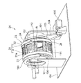
以下、本発明のシート融着体の製造装置の一実施形態であるレーザー式接合装置20について詳細に説明する。レーザー式接合装置20は、図5及び図6に示すように、第1面21a及びそれと反対側に位置する第2面21bを有する支持部材21と、支持部材21の第2面21b側に配置されたレーザー光照射部50と、ベルト式加圧装置60とを備えている。
Hereinafter, the laser-
支持部材21は、おむつ連続体10、即ち、少なくとも一部に樹脂材を含む複数枚のシートが重ねられた帯状のシート積層体10を、その長手方向にわたって第1面21a上に支持しつつこれを該長手方向に搬送する。支持部材21は、レーザー式接合装置20においては、おむつ連続体10の搬送方向に対応して回転軸周りに矢印R方向に回転動作する環状をなし、中空の円筒ロール23の周面部(被加工物との当接部)を形成し、円筒ロール23の左右両側縁部を形成する一対の環状の枠体22,22間に挟持固定されている。即ち、レーザー式接合装置20における支持部材21は、図5中矢印Rで示す方向に回転可能な円筒形状をなし、外方を向く第1面21a(外周面)と内方を向く第2面21b(内周面)とを有する。支持部材21及び枠体22は、鉄、アルミニウム、ステンレス鋼、銅等の金属材料又はセラミックス等の耐熱性を有する材料からなる。
The
支持部材21には、図5及び図6に示すように、レーザー光が通過可能な複数の光通過部24がおむつ連続体10の搬送方向、即ち、環状の支持部材21(円筒ロール23)の回転方向Rに間欠的に設けられている。より具体的には、レーザー式接合装置20における光通過部24は、支持部材21を厚み方向に貫通するスリット状の開口部であり、平面視して幅方向CDに長い長方形形状をなし、その長手方向を環状の支持部材21(円筒ロール23)の回転軸と平行な方向に一致させて、該支持部材21の周方向に所定間隔を置いて複数(8個)形成されている。ここで、「幅方向CD」は、おむつ連続体10(帯状のシート積層体)の搬送方向MD1と直交する方向であり、支持部材21の幅方向あるいは回転軸方向と同方向である。また、「平面視」は、光通過部24等の目視対象物を、支持部材21の第1面21a(外周面)の法線方向の外方から見た場合を意味する。支持部材21は、光通過部24においてレーザー光を通過させるが、光通過部24以外の部分ではレーザー光を通過させない。
As shown in FIGS. 5 and 6, the
ベルト式加圧装置60は、支持部材21の第1面21a上に支持されたおむつ連続体10を加圧する加圧部材である、無端状の加圧ベルト61と、該加圧ベルト61が架け渡された状態で回転する複数本(4本)のロール62a,62b,62c,62dとを備えている。これら複数本のロールは駆動ロールでも良く、円筒ロール23に連れ回りする従動ロールでも良い。加圧ベルト61は、ロール62a,62b,62c,62d、円筒ロール23の何れか1以上を回転駆動して、円筒ロール23と同速度で移動する。支持部材21及び加圧ベルト61は、空冷、水冷等により温度を所定の温度範囲に維持することが好ましい。加圧ベルト61としては、加工時に発生する熱に耐えうる耐熱性を有する金属又は樹脂製のベルトが好ましい。また、加圧ベルト61としては、通常、被加工物(おむつ連続体10)に対して照射されるレーザー光の透過性を有しないものが用いられるが、該透過性を有するものを用いることもできる。また、レーザー式接合装置20は、支持部材21の第1面21aに巻き掛ける加圧ベルト61の張力を増減調整できる張力調整機構(図示せず)を備え、該張力の調整により、支持部材21と加圧ベルト61とによって、おむつ連続体10に加える圧力を適宜調整することができるようになされている。
The belt-
円筒ロール23についてさらに説明すると、図7及び図8に示すように、円筒ロール23は、基台100上に立設された一対の側板101によって支持されている。円筒ロール23は固定軸102を有する。固定軸102が、対向する一対の側板101間に架け渡されることで、円筒ロール23は側板101間に支持される。円筒ロール23と固定軸102との間にはベアリング106が配置されており、該ベアリング106によって円筒ロール23は固定軸102に対して回転可能になされている。円筒ロール23は、一方の枠体22と一方の側板101との間に位置するプーリ103を有する。プーリ103には駆動ベルト104が架け渡されている。駆動ベルト104は、基台100上に載置された駆動源105に接続されている。駆動源105を駆動させることで、回転運動が駆動ベルト104を介してプーリ103に伝達されて、円筒ロール23(支持部材21)は矢印Rで示す方向に回転する。
The
円筒ロール23を構成する支持部材21は、図7及び図8に示すように、第1支持部111と第2支持部112とが周方向に交互に配置されて構成されている。即ち、円筒ロール23の周面を形成する、支持部材21の第1面21a及び第2面21bは、第1支持部111と第2支持部112とを含んで構成されている。尚、図7及び図8では、円筒ロール23の内部構造の理解を助けるために、一部の第1支持部111が取り外された状態が示されている。実際には、円筒ロール23の周面は、その全域が第1支持部111及び第2支持部112で構成されており、該周面を通じては、該円筒ロール23の内部は視認できない。
As shown in FIGS. 7 and 8, the
第2支持部112は、図8に示すように、その内面即ち支持部材21の第2面21bに凹部120を有している。凹部120は、円筒ロール23の回転方向Rに沿う断面視において、第2面21bから第1面21aに向かって回転方向Rに沿う長さが漸次減少する等脚台形状部分をなしている。凹部120の底部は開口してスリット状の開口部を形成し、その開口部が光通過部24となっている。
As shown in FIG. 8, the
支持部材21の第1面21aは、搬送されるおむつ連続体10との対向面であり、第1面21aを形成する第1支持部111の外面には、図8に示すように、多数の吸引孔111aが設けられている。吸引孔111aは、幅方向CDに延びるように穿設された連通孔111bと連通している。連通孔111bは、第1支持部111の側面において開口している。また、第2支持部112は、幅方向CDに延びるように穿設された連通孔112bを有している。連通孔112bは、第2支持部112の凹部120の壁面に形成された複数の吸引孔(図示せず)と連通し、かつ第2支持部112の側面において開口している。この凹部120の壁面に形成された図示しない吸引孔は、レーザー光の照射によるおむつ連続体10の分断及び融着時に発生する、ガスを吸引して除去するためのものである。
The
第1支持部111の連通孔111b及び第2支持部112の連通孔112bは、図7に示す吸引リング130と連通している。詳細には、吸引リング130は、円筒ロール23の側面に配置されており円筒ロール23の回転とは独立して固定状態となっている。吸引リング130における円筒ロール23との対向面には開口(図示せず)が設けられている。この開口は、連通孔111b及び112bと連通する位置に設けられている。更に、この開口は、吸引源(図示せず)とも連通している。従って、円筒ロール23が回転しているときは、吸引リング130の開口と連通した連通孔111b及び112bのみが吸引路を形成し、それによって、該吸引路の延長上にある吸引孔111a及び凹部120の壁面に形成された吸引孔(図示せず)のみから吸引が行われる。吸引リング130は、レーザー光照射部50によるレーザー光の照射範囲にわたって設けられているので、レーザー光の照射範囲では、必ず吸引が行われることになる。第1支持部111の吸引孔111aから吸引がなされると、該吸引孔111aを覆うように第1支持部111の外面に当接しているおむつ連続体10は該外面に吸引保持されるため、少なくともレーザー光の照射範囲においては、おむつ連続体10は支持部材21の第1面21a上に固定され、それによって、レーザー光の照射によるおむつ連続体10の加工精度をより一層高めることが可能となる。
The
レーザー式接合装置20の主たる特徴の1つとして、図5及び図6に示すように、支持部材21の複数の光通過部24に対応して、複数のレーザー光照射部50が支持部材21と一体化して配設されている点が挙げられる。複数のレーザー光照射部50は、それぞれ、対応する光通過部24と対向する位置に配設されている。
As one of the main features of the laser-
図9には、支持部材21の第2面21bの一部、より具体的には第2支持部112の内面が示されている。第2支持部112が有する凹部120は、支持部材21の第1面21a(外周面)及び第2面21b(内周面)それぞれに開口部24,25を有し、第1面21aにおいて幅方向CDに延びるスリット状の開口部24が、光通過部24である。そして、凹部120の第2面21bの開口部25の近傍には、開口部25と対向する光通過部24に対応する(即ち該光通過部24専用の)レーザー光照射部50が1個配置されている。前述したように、レーザー式接合装置20における支持部材21は、複数(8個)の第2支持部112を含んで構成されているところ、図9に示していない他の第2支持部112についても図9に示す如く構成されている。このように、レーザー式接合装置20においては、複数(8個)の光通過部24に対してこれと同数のレーザー光照射部50が1体1で対応している。
FIG. 9 shows a part of the
レーザー光照射部50は、凹部120の開口部25に沿って(即ち光通過部24に沿って)幅方向CDに摺動自在に配されたスライダー51に固定されている。スライダー51は、台座52上を摺動自在に配されている。台座52は、第2面21bにおける、開口部25の回転方向Rの先端側の開口端部に固定されており、開口部25に沿って幅方向CDに延びている。スライダー51は、台座52上に配されたサーボモータ53に送りねじ54を介して接続されており、サーボモータ53の動作によって台座52上を幅方向CDに往復動する。サーボモータ53は、図示しない数値制御装置と電気的に接続されている。この数値制御装置は、サーボモータ53をはじめとする、レーザー式接合装置20全体を実質的に制御するマイクロコンピュータ等のCPUと、該CPUにより実行される制御プログラムや各種データ等の必要な固定情報を格納したROMと、該CPUによる処理の実行時におけるワークエリアとして使用されるRAMと、該数値制御装置のオペレーター用入力装置等を備えている。
The laser
レーザー光照射部50は、レーザー光源(図示せず)と光ファイバ等の接続手段(図示せず)を介して接続されている。レーザー光照射部50は、前記接続手段(図示せず)により誘導されたレーザー光を平行光束に変換する第1のレンズ(図示せず)と、レーザー光を集束させる第2のレンズ(図示せず)とを含んで構成され、該第2のレンズによって収束されたレーザー光を被加工物(おむつ連続体10)に向けて照射する。レーザー光照射部50としては、公知のレーザー光照射器を用いることができ、前記レーザー光源と前記接続手段とが一体化された構成のものを用いることもできる。
The laser
スライダー51に固定されたレーザー光照射部50は、光通過部24における回転方向R(幅方向CDと直交する方向)の中心を通って円筒ロール23の周面(即ち支持部材21の第1面21a,第2面21b)の法線方向に延びる、図示しない仮想直線上に位置している。この仮想直線は、レーザー光照射部50から照射されるレーザー光について、被加工物(おむつ連続体10)にシール不良の無い高品質のシール縁部を形成し得る、「理想的な光路」であり、該仮想直線上にレーザー光照射部50が位置している限り、被加工物の所望の位置にレーザー光を高精度で照射することが可能である。レーザー光照射部50は、これに連結しているスライダー51の動作によって幅方向CDに往復動している最中、前記「理想的な光路」上に位置している。つまり、スライダー51に固定されたレーザー光照射部50は常時、レーザー光の照射目標位置である、「光通過部24の回転方向Rの中心」と相対向する定位置にあり、その定位置から照射されたレーザー光は、光通過部24の該中心を通って被加工物(おむつ連続体10)に精度良く照射される。
The laser
このように、レーザー式接合装置20においては、環状(円筒形状)をなす支持部材21に、複数の光通過部24がその周方向(おむつ連続体10の搬送方向MD1)に間欠的に設けられ、且つその複数の光通過部24に対応して、これと同数の複数のレーザー光照射部50が支持部材21と一体化して配設されている。そして、それら複数のレーザー光照射部50は、それぞれ、対応する光通過部24に対向する位置に配設され、支持部材21の回転動作中に、光通過部24の長手方向(幅方向CD)に沿って移動しつつ該光通過部24に向けてレーザー光を照射可能になされている。斯かる構成を有するレーザー式接合装置20によれば、レーザー光照射部50から対応する光通過部24に向けてレーザー光が高精度で照射されるため、高品質のシート融着体を効率良く製造することができ、従って、「複数枚のシートの縁部が重なった状態で融着したシール縁部を有するシート融着体」としての外装体3を具備する、高品質のパンツ型使い捨ておむつ1を効率良く製造することができる。
As described above, in the laser-
前述したように、特許文献2記載のレーザー式接合装置においては、レーザー光を照射する照射ヘッドが、回転動作する支持部材の回転中心位置に固定され、該支持部材とは別体であるため、該照射ヘッドから該支持部材の光通過部に対して一定時間レーザー光を照射する際には、該照射ヘッドの向き(レーザー光の照射方向)を、該支持部材の回転動作に伴って移動する該光通過部に精度良く追従させる必要があるところ、斯かる照射ヘッドの光通過部に対する追従動作には非常に高度な制御技術が要求される。特許文献2記載のレーザー式接合装置は、斯かる照射ヘッドの動きの制御の点で改良の余地があった。
As described above, in the laser-type bonding apparatus described in
これに対し、本発明に係るレーザー式接合装置20においては、回転動作する支持部材21の光通過部24に対応して、該光通過部24専用のレーザー光照射部50が、適切な位置・向きを持って支持部材21に取り付けられ、支持部材21と共に回転しながら、幅方向CDに往復動しつつ、該光通過部24に向けてレーザー光を照射するため、レーザー光の照射方向を支持部材21の回転動作に追従させるような、高度な制御技術は不要であり、レーザー光照射部50から対応する光通過部24に向けてレーザー光が高精度で照射される。
On the other hand, in the laser
レーザー光照射部50は、光通過部24の長手方向即ち幅方向CDに沿った移動における移動速度を任意に変更可能になされている。即ち、レーザー光照射部50は、対応する光通過部24の幅方向CDに沿って、一定の速度で移動することもできるし、移動速度を適宜変化させて移動することもできる。レーザー光照射部50の移動速度は、例えば、サーボモータ53に接続された前記数値制御装置によって制御することができる。従って例えば、レーザー光照射部50の移動方向(幅方向CD)における被加工物であるシート積層体(おむつ連続体10)の特性(切断性)の変化に応じて、レーザー光照射部50の移動速度を変化させることが可能である。具体的には例えば、おむつ連続体10におけるレーザー光の照射対象部分である、サイドシール部4の形成予定部分10Cが、幅方向CDにおいて厚みが異なっていて不均一である場合、該部分10Cにおける、相対的に厚みが大きく切断するにはより多くのエネルギーが必要な肉厚部に対して、レーザー光を照射する場合は、レーザー光照射部50の移動速度を相対的に遅くし、また、該部分10Cにおける、相対的に厚みが小さくより小さなエネルギーで切断可能な肉薄部に対して、レーザー光を照射する場合は、レーザー光照射部50の移動速度を相対的に速くする、という操作が可能である。
The laser
また例えば、シール縁部(例えばおむつ連続体10のサイドシート4)のシール強度(融着強度)を、均一にせずに意図的に部分的に異ならせて、シール縁部全体としてシール強度に強弱をつけたい場合には、レーザー光照射部50の移動速度を変化させながらシート積層体(おむつ連続体10)にレーザー光を照射することで、所望のシール縁部(サイドシール部4)が得られる。このようなシール強度の変化付けは、シール縁部の形成予定部分の特性(例えば厚みの均一性)如何にかかわらず、任意に実施できる。
Further, for example, the seal strength (fusion strength) of the seal edge (for example, the
レーザー光照射部50から照射されるレーザー光は、被加工物であるおむつ連続体10(シート積層体)を構成するシートに吸収され該シートを発熱させる波長のレーザー光である。ここで、「シート積層体を構成するシート」は、シート積層体の一方の面(支持部材21との当接面)を構成するシート(例えば外層シート31)に限定されず、シート積層体を構成するシートであればどれであっても良い。シート積層体に照射するレーザー光が、該シート積層体を構成する個々のシートについて、該シートに吸収されて該シートを発熱させる波長であるか否かは、シートの材質と、使用するレーザー光の波長との関係で決まる。シート積層体を構成するシートが、使い捨ておむつや生理用ナプキン等の吸収性物品(サニタリー用品)の製造に汎用される合成樹脂製の不織布やフィルムである場合、レーザー光としては、CO2レーザー、YAGレーザー、LDレーザー(半導体レーザー)、YVO4レーザー、ファイバーレーザー等を用いることが好ましい。また、シート積層体を構成するシートが、合成樹脂として、ポリエチレン、ポリエチレンテレフタレート、ポリプロピレン等を含む場合、該シートに吸収され該シートを良好に発熱させ得る波長としては、例えば、8.0μm以上15μm以下を用いることが好ましく、高出力のレーザー装置が存在するCO2レーザーの発振波長の9.0μm以上11.0μm以下を用いることが特に好ましい。レーザー光のスポット径、レーザー出力等は、シート積層体を構成するシートの材質や厚み等を考慮して適宜選択することができる。
The laser light irradiated from the laser
レーザー式接合装置20を用いておむつ連続体10を個々のおむつ1に分断すること、即ち、おむつ連続体10からパンツ型使い捨ておむつ1を製造することは、例えば、図5及び図6に示す如き方法で実施することができる。
Dividing the diaper
図5及び図6に示すおむつ1の製造方法の一実施態様は、搬送工程とレーザー光照射工程とを有する。
前記搬送工程は、円筒形状の支持部材21の第1面21a(外周面)上におむつ連続体10(帯状のシート積層体)を加圧状態で支持させ、支持部材21を符号Rで示す方向に回転動作させることによっておむつ連続体10をその長手方向に搬送する工程である。
前記レーザー光照射工程は、支持部材21の第2面21b側に配置されたレーザー光照射部50から、支持部材21に設けられた、おむつ連続体10の幅方向CDに長い光通過部24に沿ってレーザー光を照射することにより、支持部材21の第1面21a上に光通過部24を覆うように加圧状態で支持されたおむつ連続体10にレーザー光を照射し、それによっておむつ連続体10を分断するのと同時に、その分断によって生じた複数枚のシートの切断縁部どうしを融着させてサイドシール部4(シール縁部)を形成する工程である。
本発明には、おむつ1の如き吸収性物品の製造方法として、このような、搬送工程及びレーザー照射工程を有するシート融着体の製造方法によりシート融着体を製造する工程を含むものが含まれる。おむつ1におけるシート融着体は、前述した通り外装体3である。
One embodiment of the manufacturing method of the
In the transporting process, the diaper continuous body 10 (band-shaped sheet laminate) is supported in a pressurized state on the
The laser beam irradiation step is performed from the laser
In the present invention, the manufacturing method of the absorbent article such as the
図5及び図6に示すおむつ1の製造方法の一実施態様においては、おむつ連続体10は、図示しない案内ロール等によって所定のテンションが掛けられた状態で、符号MD1で示す方向に搬送され、矢印R方向に回転駆動される円筒ロール23の周面部を形成する支持部材21の第1面21a上に導入され、該第1面21aに巻き掛けられて円筒ロール23の回転によりその周方向に所定距離搬送される。その円筒ロール23による搬送の際には、支持部材21の第1面21aに当接され且つ所定のテンションが掛けられている、おむつ連続体10に対し、支持部材21側とは反対側から加圧ベルト61を押し付けて加圧状態とし、その加圧状態のおむつ連続体10に対して、支持部材21の第2面21b側から光通過部24に沿って、レーザー光をレーザー光照射部50から照射する。これにより、おむつ連続体10が個々に分断され、また、その分断によって生じた加圧状態にある複数枚のシートの切断縁部どうしが融着してシール縁部を形成する。こうして、一対のサイドシール部4,4(シール縁部)を有する外装体3(シート融着体)を具備する、複数のパンツ型使い捨ておむつ1(シート融着体)が連続的に製造される。複数のおむつ1は順次、図示しない導出ロール及びニップロール等によって支持部材21から離れ、図5及び図6中符号MD2で示す、おむつ連続体10の搬送方向MD1とは逆方向に搬送され、次工程に送られる。
In one embodiment of the manufacturing method of the
このように、おむつ連続体10を、支持部材21に所定のテンションで巻き掛け且つ加圧ベルト61によって圧接するようにして搬送することにより、おむつ連続体10における支持部材21と加圧ベルト61とに挟まれた部分及びその近傍は、レーザー光の照射による分断前からその厚み方向に加圧された状態となるため、おむつ連続体10が不織布を含む場合等に、該おむつ連続体10をより効率的に圧縮させることができ、結果として、斯かる圧縮中のおむつ連続体10に対して、レーザー光照射部50からレーザー光を照射してこれを分断したときに、その分断された部分を構成する複数枚のシートの切断縁部どうしをより確実に融着させることが可能となり、サイドシール部4(シール縁部)の融着強度の一層の向上が図られる。
As described above, the diaper
尚、レーザー式接合装置20においては、おむつ連続体10における光通過部24と重なる部分、即ち分断予定部分10Cは、片面側から加圧ベルト61が当接するだけで、支持部材21と加圧ベルト61とで挟まれない。従って厳密に言えば、分断予定部分10Cには、両部材21,41で挟持されることにより発生する加圧力は発生しない。しかし、光通過部24と重なる分断予定部分10Cは、それ自体は両部材21,41で挟持されなくとも、その近傍、即ち、おむつ連続体10における光通過部24の近傍と重なる部分は両部材21,41で挟持されるため、レーザー光の照射前後で動かず、従って、レーザー光の照射によるおむつ連続体10の分断によって生じた切断縁部は動かない。つまり、おむつ連続体10の分断予定部分10Cは、両部材21,41での挟持による加圧力により拘束された部分であり、該加圧力が事実上影響する部分である。
In the laser-
図10には、レーザー式接合装置20を用いておむつ連続体10(帯状のシート積層体)を分断するのと同時にサイドシール部4(シール縁部)を形成する様子が示されている。おむつ連続体10の分断予定部分10Cは、おむつ連続体10の吸収性本体2が配置されていない領域における搬送方向MD1の中央である。斯かる分断予定部分10Cは、ウエスト開口部8(図1参照)の開口端部及びその近傍が、8枚のシートが重ねられた8層構造部分、それ以外の部分が、4枚のシートが重ねられた4層構造部分となっている。4層構造部分は、図10(a)に示すように、腹側部1Aにおける1枚の外装体3を構成する2枚のシート(外層シート31及び内層シート32)と、背側部1Bにおける1枚の外装体3を構成する同じく2枚のシート31,32とからなり、これら4枚のシートが積層されて構成されている。一方、8層構造部分は、図4に示すように、おむつ連続体10の製造時に帯状の外装体3の両側部3a,3aが吸収性本体2の長手方向両端部を覆うように折り返されていることに起因して、腹側部1A及び背側部1Bそれぞれに外装体3が2枚存し且つこれら計4枚の外装体3,3が積層されているので、結果として8枚のシート31,32が積層されて構成されている。尚、4層構造部分及び8層構造部分それぞれにおいて、互いに重なり合うシート31,32間には、ウエスト部弾性部材5、胴回り部弾性部材6等の弾性部材が介在配置されている場合があるが、図10では、説明容易の観点から、該弾性部材の図示を省略している。以下、主として、4層構造部分について説明するが、特に断らない限り、8層構造部分も4層構造部分と同様に構成されサイドシール部4が形成される。
FIG. 10 shows a state in which the side seal portion 4 (seal edge) is formed at the same time as the diaper continuous body 10 (band-shaped sheet laminate) is divided using the
おむつ連続体10における4層構造の分断予定部分10Cにおいて、おむつ連続体10の一方の面10a(支持部材21との当接面)を構成する外層シート31及び一方の面10aを構成するシート以外のシート(内層シート32)は、何れか一方又は両方が、レーザー光30を吸収して発熱するシートである。図示の形態においては、分断予定部分10Cを構成する4枚のシート31,32のすべてが、レーザー光30を吸収して発熱するシート(不織布)である。また、分断予定部分10C及びその近傍における互いに重なり合う2枚のシート間は、レーザー光30の照射前において、接着剤等により接合されていても良く、全く接合されていなくても良い。
Other than the sheet constituting the
おむつ連続体10は、図10(b)に示すように、一方の面10aが支持部材21に当接し且つ分断予定部分10Cが光通過部24上に位置するように、矢印R方向に回転する支持部材21上に導入されると共に、他方の面10bに加圧ベルト61が押し付けられることによって、矢印R方向に搬送されつつ厚み方向に加圧される。そして、斯かる搬送中且つ加圧状態の分断予定部分10Cに対して、支持部材21側から光通過部24に沿ってレーザー光照射部50からレーザー光30が照射される。
As shown in FIG. 10B, the diaper
4層構造の分断予定部分10Cにレーザー光30が照射されると、該分断予定部分10Cに存するシート31,32の形成材料(繊維等)は、レーザー光30の直射による発熱によって気化して消失し、該分断予定部分10Cの近傍に存する該形成材料は、レーザー光30によって間接的に熱せされて溶融する。その結果、図10(c)に示すように、4層構造の分断予定部分10Cが溶断されて、おむつ連続体10から1つの枚葉のシート積層体(おむつ前駆体)が切り分けられる形で、該おむつ連続体10が分断されるのと同時に、その分断によって生じた該枚葉のシート積層体における4枚のシート31,32の切断縁部どうし、及び、切り分けられた該おむつ連続体10における4枚のシート31,32の切断縁部どうしが、それぞれ融着して融着部40が形成される。これらの切断縁部どうしは、それぞれ、その形成前(レーザー光30の照射によるおむつ連続体10の分断前)から、支持部材21と加圧ベルト61とに挟まれることによって加圧状態(圧縮状態)とされていたものである。融着部40の形状は、図10(c)に示す通り、例えば三日月状となる。
When the
シート31,32の切断縁部は、レーザー光30の照射中及び照射終了直後は、発熱して溶融状態となっているが、レーザー光30の照射によっておむつ連続体10から切り分けられた1つの枚葉のシート積層体(おむつ前駆体)及び該おむつ連続体10それぞれの、支持部材21と加圧ベルト61とによる加圧状態が保持されたまま、照射終了後からは外気や支持部材21・加圧ベルト61への伝熱によって速やかに冷却されて固化し、該切断縁部の形成材料(繊維等)が溶融一体化した融着部40となる。こうして、融着部40が形成されることによって、1個のおむつ1における一対のサイドシール部4,4のうちの一方が形成される。
The cut edges of the
前述したように、レーザー式接合装置20においては、複数の光通過部24に対応して複数のレーザー光照射部50が配置されているため、その対応関係ごとに、他の対応関係から独立して、図10に示す如く融着部40(サイドシール部4)を形成することが可能である。従って、レーザー式接合装置20によれば、おむつ連続体10の複数の分断予定部分10Cに同時に融着部40を形成することも可能である。
As described above, in the laser-
レーザー式接合装置20における複数のレーザー光照射部50は、それぞれ、円筒ロール23(支持部材21)が一回転するごとに、対応する光通過部24に沿った移動路を一往復するようになされている。図11には、円筒ロール23の一回転中における、1個のレーザー光照射部50の対応する光通過部24に沿った移動の様子が示されている。レーザー光照射部50の移動路は、スライダー51等からなる該レーザー光照射部50の移動機構によって定められおり、図11に示すように、送りねじ54と平行で且つ対応する光通過部24の回転方向Rの中心と相対向する。
Each of the plurality of laser
図11では、1個のレーザー光照射部50に注目して、円筒ロール23の一回転中における該1個のレーザー光照射部50の位置の経時変化を、(1)〜(5)として5つに分けて順番に示しており、(1)の状態から始まって(5)の状態になったときに、円筒ロール23はちょうど一回転する。先ず、図11の(1)の状態において、前記移動路の幅方向CDの一端に位置しているレーザー光照射部50は、相対向する光通過部24に向けてレーザー光の照射を開始すると共に、幅方向CDの他端に向かって移動を開始し、図11の(2)の状態を経て、図11の(3)に示すように幅方向CDの他端に到達するまでレーザー光を照射し続け、図11の(3)に示す状態になった時点でレーザー光の照射を終了する。図11の(1)に示す状態から図11の(3)に示す状態に至るまでの間、円筒ロール23は方向Rに一定速度で回転しており、その回転によってレーザー光照射部50は、例えば、円筒ロール23の中心角にして120°移動する。次いで、図11の(3)の状態において、前記移動路の幅方向CDの他端に位置しているレーザー光照射部50は、幅方向CDの一端(初期位置)に向かって移動を開始し、図11の(4)の状態を経て、図11の(5)に示すように初期位置に戻る。図11(3)に示す状態から図11(5)に示す状態に至るまでの間、レーザー光照射部50からレーザー光は一切照射されない。こうして、図11の(1)に示す状態から始まって図11の(5)に示す状態に至るまでの間、レーザー光照射部50は、円筒ロール23の中心角にして約360°移動する。レーザー式接合装置20においては、複数のレーザー光照射部50それぞれが、図11に示す如き態様で移動しレーザー光を照射するように制御すること、即ち、レーザー光照射部50が前記移動路の一端側から他端側に移動中は、該レーザー光照射部50からレーザー光を照射させ、これとは逆方向即ち該他端側から該一端側に移動中は、該レーザー光照射部50からレーザー光を照射させないように制御することが可能である。
In FIG. 11, paying attention to one laser
以上、本発明をその実施形態に基づいて説明したが、本発明は、前記実施形態に制限されることなく、本発明の趣旨を逸脱しない範囲で適宜変更が可能である。
例えば、前記実施形態においては、レーザー光照射部50及びその移動機構(スライダー51等)は、図9に示すように、凹部120の開口部25の回転方向Rの先端側に配置されていたが、回転方向Rの後端側に配置されていても良い。
また、レーザー光照射部50を光通過部24に沿って移動させる移動機構は、前述したサーボモータを駆動源とするものに限定されず、この種の移動機構として公知のものを特に制限なく利用することができ、例えば、空圧式アクチュエータ、油圧式アクチュエータ等を駆動源とするものを利用することができる。
前述した本発明の実施形態に関し、更に以下の付記を開示する。
As mentioned above, although this invention was demonstrated based on the embodiment, this invention is not restrict | limited to the said embodiment, In the range which does not deviate from the meaning of this invention, it can change suitably.
For example, in the above-described embodiment, the laser
Further, the moving mechanism for moving the laser
The following additional notes are disclosed with respect to the embodiment of the present invention described above.
<1>
複数枚のシートの縁部が重なった状態で融着したシール縁部を有するシート融着体の製造方法であって、
前記複数枚のシートの少なくとも一部のシートは樹脂材を含み、
第1面及びそれと反対側に位置する第2面を有する支持部材の該第1面上に、前記複数枚のシートが重ねられた構成を有する帯状のシート積層体を加圧状態で支持させ、該支持部材を動作させることによって該シート積層体をその長手方向に搬送する搬送工程と、
前記支持部材の前記第2面側に配置されたレーザー光照射部から、該支持部材に設けられた、前記シート積層体の幅方向に長い光通過部に沿ってレーザー光を照射することにより、該支持部材の前記第1面上に該光通過部を覆うように加圧状態で支持された該シート積層体にレーザー光を照射し、それによって該シート積層体を分断するのと同時に、その分断によって生じた前記複数枚のシートの切断縁部どうしを融着させて前記シール縁部を形成するレーザー光照射工程とを有し、
前記支持部材に、複数の前記光通過部が前記シート積層体の搬送方向に間欠的に設けられ、且つその複数の光通過部に対応して、複数の前記レーザー光照射部が該支持部材と一体化して配設されている、シート融着体の製造方法。
<1>
A method for producing a sheet fusion body having a seal edge fused in a state where edges of a plurality of sheets are overlapped,
At least a part of the plurality of sheets includes a resin material,
On the first surface of the support member having the first surface and the second surface located on the opposite side, the belt-shaped sheet laminate having a configuration in which the plurality of sheets are stacked is supported in a pressurized state. A transporting step of transporting the sheet laminate in its longitudinal direction by operating the support member;
By irradiating the laser beam along the light passing portion provided in the support member and extending in the width direction of the sheet laminate, from the laser beam irradiation portion disposed on the second surface side of the support member, At the same time as irradiating the sheet laminated body supported in a pressurized state on the first surface of the support member so as to cover the light passage part, thereby dividing the sheet laminated body, A laser beam irradiation step of forming the seal edge by fusing the cut edges of the plurality of sheets generated by the division,
The support member is provided with a plurality of light passage portions intermittently in the conveying direction of the sheet laminate, and a plurality of the laser light irradiation portions correspond to the plurality of light passage portions and the support member. The manufacturing method of the sheet | seat melt | fusion body arrange | positioned integrally.
<2>
複数の前記光通過部に対して複数の前記レーザー光照射部が1体1で対応し、
複数の前記レーザー光照射部は、それぞれ、対応する前記光通過部と対向する位置に配設され、且つ前記支持部材の動作中に、該光通過部の長手方向に沿って移動しつつ該光通過部に向けてレーザー光を照射可能になされている前記<2>に記載のシート融着体の製造方法。
<3>
前記レーザー光照射部は、前記光通過部の長手方向に沿った移動における移動速度を任意に変更可能になされており、該レーザー光照射部の移動速度を変化させながら前記シート積層体にレーザー光を照射する前記<2>に記載のシート融着体の製造方法。
<4>
前記シート積層体におけるレーザー光の照射対象部分即ち前記シール縁部の形成予定部分が、該シート積層体の幅方向において厚みが不均一である場合において、
前記レーザー光照射工程では、前記照射対象部分における相対的に厚みの大きい肉厚部にレーザー光を照射する場合は、前記レーザー光照射部の移動速度を相対的に遅くし、該照射対象部分における相対的に厚みの小さい肉薄部にレーザー光を照射する場合は、該レーザー光照射部の移動速度を相対的に速くする前記<3>に記載のシート融着体の製造方法。
<2>
A plurality of the laser beam irradiation units correspond to a plurality of the light passage units in one
Each of the plurality of laser beam irradiation units is disposed at a position facing the corresponding light passage unit, and moves while moving along the longitudinal direction of the light passage unit during operation of the support member. The method for producing a sheet fusion body according to <2>, wherein the laser beam can be irradiated toward the passage portion.
<3>
The laser beam irradiation unit can arbitrarily change the moving speed in the movement along the longitudinal direction of the light passage unit, and the laser beam is applied to the sheet laminate while changing the moving speed of the laser beam irradiation unit. The method for producing a sheet-fused body according to <2>, wherein irradiation is performed.
<4>
In the case where the portion to be irradiated with the laser beam in the sheet laminate, that is, the portion to be formed of the seal edge is non-uniform in the width direction of the sheet laminate,
In the laser beam irradiation step, when irradiating a laser beam to a relatively thick wall portion in the irradiation target portion, the moving speed of the laser beam irradiation portion is relatively slow, In the case of irradiating a laser beam to a thin part having a relatively small thickness, the method for producing a sheet fusion body according to <3>, wherein the moving speed of the laser beam irradiation part is relatively increased.
<5>
前記支持部材は、前記シート積層体の搬送方向に対応して回転軸周りに回転動作し、該支持部材が一回転するごとに、前記レーザー光照射部が、対応する前記光通過部に沿った移動路を一往復するようになされている前記<2>〜<4>の何れか一項に記載のシート融着体の製造方法。
<6>
前記レーザー光照射部が前記移動路の一端側から他端側に移動中は、該レーザー光照射部からレーザー光を照射させ、これとは逆方向に移動中は、該レーザー光照射部からレーザー光を照射させない前記<5>に記載のシート融着体の製造方法。
<7>
前記<1>〜<6>の何れか一項に記載の製造方法により前記シート融着体を製造する工程を含む、吸収性物品の製造方法。
<8>
前記吸収性物品がパンツ型使い捨ておむつである前記<7>に記載の吸収性物品の製造方法。
<5>
The support member rotates around a rotation axis corresponding to the conveying direction of the sheet laminate, and each time the support member rotates, the laser beam irradiation unit is aligned with the corresponding light passing unit. The method for producing a sheet fusion body according to any one of <2> to <4>, wherein the sheet is made to reciprocate once along a moving path.
<6>
While the laser beam irradiation unit is moving from one end side to the other end side of the moving path, the laser beam irradiation unit irradiates the laser beam, and when moving in the opposite direction, the laser beam irradiation unit emits a laser beam. The method for producing a sheet fusion body according to <5>, wherein the sheet is not irradiated with light.
<7>
The manufacturing method of an absorbent article including the process of manufacturing the said sheet | seat fusion body by the manufacturing method as described in any one of said <1>-<6>.
<8>
The method for producing an absorbent article according to <7>, wherein the absorbent article is a pants-type disposable diaper.
<9>
複数枚のシートの縁部が重なった状態で融着したシール縁部を有するシート融着体の製造装置であって、
第1面及びそれと反対側に位置する第2面を有し、少なくとも一部に樹脂材を含む複数枚のシートが重ねられた帯状のシート積層体をその長手方向にわたって該第1面上に支持しつつこれを該長手方向に搬送する支持部材と、
前記支持部材の前記第2面側に配置されたレーザー光照射部とを具備し、
前記支持部材に、レーザー光が通過可能な複数の光通過部が前記シート積層体の搬送方向に間欠的に設けられ、且つその複数の光通過部に対応して、複数の前記レーザー光照射部が該支持部材と一体化して配設されている、シート融着体の製造装置。
<9>
An apparatus for producing a sheet fusion body having a seal edge fused in a state where edges of a plurality of sheets overlap with each other,
A belt-like sheet laminate having a first surface and a second surface located opposite to the first surface and a plurality of sheets including a resin material at least partially overlapped is supported on the first surface over the longitudinal direction. And a support member that conveys this in the longitudinal direction,
A laser beam irradiation unit disposed on the second surface side of the support member,
The support member is provided with a plurality of light passage portions through which laser light can pass intermittently in the conveying direction of the sheet laminate, and a plurality of the laser light irradiation portions corresponding to the plurality of light passage portions. Is an apparatus for manufacturing a sheet-fused body, wherein the apparatus is disposed integrally with the support member.
<10>
複数の前記光通過部に対して複数の前記レーザー光照射部が1体1で対応し、
複数の前記レーザー光照射部は、それぞれ、対応する前記光通過部と対向する位置に配設され、且つ前記支持部材の動作中に、該光通過部の長手方向に沿って移動しつつ該光通過部に向けてレーザー光を照射可能になされている前記<9>に記載のシート融着体の製造装置。
<11>
前記レーザー光照射部は、前記光通過部の長手方向に沿った移動における移動速度を任意に変更可能になされている前記<9>又は<10>に記載のシート融着体の製造方法。
<12>
前記支持部材は、前記シート積層体の搬送方向に対応して回転軸周りに回転動作し、該支持部材が一回転するごとに、前記レーザー光照射部が、対応する前記光通過部に沿った移動路を一往復するようになされている前記<9>〜<11>の何れか一項に記載のシート融着体の製造装置。
<10>
A plurality of the laser beam irradiation units correspond to a plurality of the light passage units in one
Each of the plurality of laser beam irradiation units is disposed at a position facing the corresponding light passage unit, and moves while moving along the longitudinal direction of the light passage unit during operation of the support member. The apparatus for producing a sheet fusion body according to <9>, wherein the laser beam can be irradiated toward the passage portion.
<11>
The said laser beam irradiation part is a manufacturing method of the sheet fusion body as described in said <9> or <10> in which the moving speed in the movement along the longitudinal direction of the said light passage part can be changed arbitrarily.
<12>
The support member rotates around a rotation axis corresponding to the conveying direction of the sheet laminate, and each time the support member rotates, the laser beam irradiation unit is aligned with the corresponding light passing unit. The apparatus for producing a sheet fusion body according to any one of <9> to <11>, wherein the apparatus is configured to reciprocate once along a moving path.
<13>
前記レーザー光照射部は、前記光通過部に沿って前記搬送方向と直交する方向に摺動自在に配されたスライダーに固定されている前記<9>〜<12>の何れか一項に記載のシート融着体の製造装置。
<14>
前記スライダーは、前記支持部材の前記第2面に固定され且つ前記光通過部に沿って前記搬送方向と直交する方向に延びる、台座上を摺動自在に配されており、且つ
前記スライダーは、前記台座上に配されたサーボモータに送りねじを介して接続されており、該サーボモータの動作によって該台座上を移動可能になされている前記<13>に記載のシート融着体の製造装置。
<15>
前記レーザー光照射部は、接続手段を介してレーザー光源と接続されている前記<9>〜<14>の何れか一項に記載のシート融着体の製造装置。
<13>
The laser light irradiation unit is described in any one of <9> to <12>, which is fixed to a slider that is slidable in a direction orthogonal to the transport direction along the light passage unit. Sheet fusion product manufacturing apparatus.
<14>
The slider is slidably disposed on a pedestal that is fixed to the second surface of the support member and extends in a direction perpendicular to the transport direction along the light passage portion, and the slider is The apparatus for manufacturing a sheet fusion body according to <13>, wherein the apparatus is connected to a servo motor disposed on the pedestal via a feed screw and is movable on the pedestal by an operation of the servo motor. .
<15>
The said laser beam irradiation part is a manufacturing apparatus of the sheet fusion body as described in any one of said <9>-<14> connected with the laser light source via the connection means.
<16>
前記支持部材は、前記シート積層体の搬送方向に対応して回転軸周りに回転動作し、
前記レーザー光照射部は、前記光通過部における前記支持部材の回転方向の中心を通って該支持部材の前記第1面及び前記第2面の法線方向に延びる、仮想直線上に位置している前記<9>〜<15>の何れか一項に記載のシート融着体の製造装置。
<17>
前記支持部材の前記第1面は、搬送される前記シート積層体との対向面であり、該第1面を形成する部材の外面に、該シート積層体にレーザー光を照射したときに発生するガスを吸引除去するための吸引孔が多数設けられている前記<9>〜<16>の何れか一項に記載のシート融着体の製造装置。
<18>
さらに、前記支持部材の前記第1面上に支持された前記シート積層体を加圧する加圧部材を具備する前記<9>〜<17>の何れか一項に記載のシート融着体の製造装置。
<19>
前記加圧部材は、無端状の加圧ベルトからなり、該加圧ベルトは、回転可能な複数本のロールに架け渡されて配置されている前記<18>に記載のシート融着体の製造装置。
<16>
The support member rotates around a rotation axis corresponding to the conveying direction of the sheet laminate,
The laser beam irradiation unit is located on an imaginary straight line that extends in the normal direction of the first surface and the second surface of the support member through the center of the rotation direction of the support member in the light passage unit. The apparatus for producing a sheet fusion body according to any one of <9> to <15>.
<17>
The first surface of the support member is a surface facing the sheet laminate to be conveyed, and is generated when the outer surface of the member forming the first surface is irradiated with laser light on the sheet laminate. The apparatus for producing a sheet fusion body according to any one of <9> to <16>, wherein a plurality of suction holes for sucking and removing the gas are provided.
<18>
Furthermore, manufacture of the sheet | seat melt | fusion body as described in any one of said <9>-<17> which comprises the pressurization member which pressurizes the said sheet | seat laminated body supported on the said 1st surface of the said support member. apparatus.
<19>
The pressurizing member includes an endless pressurizing belt, and the pressurizing belt is disposed so as to be spanned between a plurality of rotatable rolls. apparatus.
1 パンツ型使い捨ておむつ
2 吸収性本体
3 外装体
31 外層シート
32 内層シート
4 サイドシール部
40 融着部
41 シール縁部
5,6,7 弾性部材
10 おむつ連続体(シート積層体)
20 レーザー式接合装置
21 支持部材
111 第1支持部
112 第2支持部
120 凹部
22 枠体
23 円筒ロール
24 光通過部
25 凹部における光通過部とは反対側の開口部
30 レーザー光
50 レーザー光照射部
51 スライダー
52 台座
53 サーボモータ
54 送りねじ
60 ベルト式加圧装置
61 加圧ベルト(加圧部材)
DESCRIPTION OF
DESCRIPTION OF
Claims (7)
前記複数枚のシートの少なくとも一部のシートは樹脂材を含み、
第1面及びそれと反対側に位置する第2面を有する支持部材の該第1面上に、前記複数枚のシートが重ねられた構成を有する帯状のシート積層体を加圧状態で支持させ、該支持部材を動作させることによって該シート積層体をその長手方向に搬送する搬送工程と、
前記支持部材の前記第2面側に配置されたレーザー光照射部から、該支持部材に設けられた、前記シート積層体の幅方向に長い光通過部に沿ってレーザー光を照射することにより、該支持部材の前記第1面上に該光通過部を覆うように加圧状態で支持された該シート積層体にレーザー光を照射し、それによって該シート積層体を分断するのと同時に、その分断によって生じた前記複数枚のシートの切断縁部どうしを融着させて前記シール縁部を形成するレーザー光照射工程とを有し、
前記支持部材に、複数の前記光通過部が前記シート積層体の搬送方向に間欠的に設けられ、且つその複数の光通過部に対応して、複数の前記レーザー光照射部が該支持部材と一体化して配設されている、シート融着体の製造方法。 A method for producing a sheet fusion body having a seal edge fused in a state where edges of a plurality of sheets are overlapped,
At least a part of the plurality of sheets includes a resin material,
On the first surface of the support member having the first surface and the second surface located on the opposite side, the belt-shaped sheet laminate having a configuration in which the plurality of sheets are stacked is supported in a pressurized state. A transporting step of transporting the sheet laminate in its longitudinal direction by operating the support member;
By irradiating the laser beam along the light passing portion provided in the support member and extending in the width direction of the sheet laminate, from the laser beam irradiation portion disposed on the second surface side of the support member, At the same time as irradiating the sheet laminated body supported in a pressurized state on the first surface of the support member so as to cover the light passage part, thereby dividing the sheet laminated body, A laser beam irradiation step of forming the seal edge by fusing the cut edges of the plurality of sheets generated by the division,
The support member is provided with a plurality of light passage portions intermittently in the conveying direction of the sheet laminate, and a plurality of the laser light irradiation portions correspond to the plurality of light passage portions and the support member. The manufacturing method of the sheet | seat melt | fusion body arrange | positioned integrally.
複数の前記レーザー光照射部は、それぞれ、対応する前記光通過部と対向する位置に配設され、且つ前記支持部材の動作中に、該光通過部の長手方向に沿って移動しつつ該光通過部に向けてレーザー光を照射可能になされている請求項1に記載のシート融着体の製造方法。 A plurality of the laser beam irradiation units correspond to a plurality of the light passage units in one body 1,
Each of the plurality of laser beam irradiation units is disposed at a position facing the corresponding light passage unit, and moves while moving along the longitudinal direction of the light passage unit during operation of the support member. The manufacturing method of the sheet | seat melt | fusion body of Claim 1 made it possible to irradiate a laser beam toward a passage part.
第1面及びそれと反対側に位置する第2面を有し、少なくとも一部に樹脂材を含む複数枚のシートが重ねられた帯状のシート積層体を該第1面上に支持しつつこれをその長手方向に搬送する支持部材と、
前記支持部材の前記第2面側に配置されたレーザー光照射部とを具備し、
前記支持部材に、レーザー光が通過可能な複数の光通過部が前記シート積層体の搬送方向に間欠的に設けられ、且つその複数の光通過部に対応して、複数の前記レーザー光照射部が該支持部材と一体化して配設されている、シート融着体の製造装置。 An apparatus for producing a sheet fusion body having a seal edge fused in a state where edges of a plurality of sheets overlap with each other,
The first surface and the second surface located on the opposite side of the first surface, and a belt-like sheet laminate in which a plurality of sheets including a resin material are overlapped at least partially are supported on the first surface. A support member for conveying in the longitudinal direction;
A laser beam irradiation unit disposed on the second surface side of the support member,
The support member is provided with a plurality of light passage portions through which laser light can pass intermittently in the conveying direction of the sheet laminate, and a plurality of the laser light irradiation portions corresponding to the plurality of light passage portions. Is an apparatus for manufacturing a sheet-fused body, wherein the apparatus is disposed integrally with the support member.
Priority Applications (1)
| Application Number | Priority Date | Filing Date | Title |
|---|---|---|---|
| JP2015205032A JP6568449B2 (en) | 2015-10-16 | 2015-10-16 | Manufacturing method and manufacturing apparatus of sheet fusion body |
Applications Claiming Priority (1)
| Application Number | Priority Date | Filing Date | Title |
|---|---|---|---|
| JP2015205032A JP6568449B2 (en) | 2015-10-16 | 2015-10-16 | Manufacturing method and manufacturing apparatus of sheet fusion body |
Publications (2)
| Publication Number | Publication Date |
|---|---|
| JP2017074762A JP2017074762A (en) | 2017-04-20 |
| JP6568449B2 true JP6568449B2 (en) | 2019-08-28 |
Family
ID=58549885
Family Applications (1)
| Application Number | Title | Priority Date | Filing Date |
|---|---|---|---|
| JP2015205032A Active JP6568449B2 (en) | 2015-10-16 | 2015-10-16 | Manufacturing method and manufacturing apparatus of sheet fusion body |
Country Status (1)
| Country | Link |
|---|---|
| JP (1) | JP6568449B2 (en) |
Families Citing this family (1)
| Publication number | Priority date | Publication date | Assignee | Title |
|---|---|---|---|---|
| JP7075304B2 (en) * | 2018-07-25 | 2022-05-25 | 花王株式会社 | Manufacturing method of sheet fused body |
-
2015
- 2015-10-16 JP JP2015205032A patent/JP6568449B2/en active Active
Also Published As
| Publication number | Publication date |
|---|---|
| JP2017074762A (en) | 2017-04-20 |
Similar Documents
| Publication | Publication Date | Title |
|---|---|---|
| JP5687732B2 (en) | Sheet fusion body manufacturing apparatus and sheet fusion body manufacturing method | |
| JP5368646B1 (en) | Manufacturing method and manufacturing apparatus of sheet fusion body | |
| WO2013172343A1 (en) | Method for manufacturing fused sheets | |
| JP5368653B1 (en) | Manufacturing method of sheet fusion body | |
| JP5766252B2 (en) | Pants-type wearing article and manufacturing method thereof | |
| WO2014103818A1 (en) | Underpants type disposable diaper and method for producing same | |
| JP5822278B2 (en) | Disposable diapers | |
| WO2015064405A1 (en) | Fused sheet manufacturing device and manufacturing method | |
| JP6228814B2 (en) | Sheet fusion body manufacturing apparatus and manufacturing method | |
| WO2016098521A1 (en) | Manufacturing method and manufacturing device for sheet melt-fusion body | |
| JP5695163B1 (en) | Manufacturing method of sheet fusion body | |
| JP6568449B2 (en) | Manufacturing method and manufacturing apparatus of sheet fusion body | |
| JP6247900B2 (en) | Sheet fusion body manufacturing equipment | |
| JP6247899B2 (en) | Sheet fusion body manufacturing apparatus and manufacturing method | |
| JP2017070464A (en) | Manufacturing apparatus and manufacturing method of sheet fused body | |
| WO2019131231A1 (en) | Device for manufacturing fused sheet, method for manufacturing fused sheet, and method for suppressing deposition of resin fume | |
| JP2019077062A (en) | Manufacturing device and manufacturing method of sheet fusion body | |
| JP2020078884A (en) | Method for manufacturing sheet welded body | |
| JP6095003B2 (en) | Sheet fusion body manufacturing apparatus and manufacturing method | |
| JP6383229B2 (en) | Sheet fusion body manufacturing apparatus and manufacturing method | |
| JP6382081B2 (en) | Sheet fusion body manufacturing apparatus and manufacturing method | |
| JP6425961B2 (en) | Slit forming device and manufacturing device for sheet fusion body | |
| JP2020082472A (en) | Apparatus for manufacturing sheet fused body | |
| JP2019076906A (en) | Laser beam irradiation device and sheet-fused body manufacturing apparatus | |
| JP2020015228A (en) | Method for manufacturing sheet fused body |
Legal Events
| Date | Code | Title | Description |
|---|---|---|---|
| RD03 | Notification of appointment of power of attorney |
Free format text: JAPANESE INTERMEDIATE CODE: A7423 Effective date: 20160219 |
|
| RD04 | Notification of resignation of power of attorney |
Free format text: JAPANESE INTERMEDIATE CODE: A7424 Effective date: 20180201 |
|
| A621 | Written request for application examination |
Free format text: JAPANESE INTERMEDIATE CODE: A621 Effective date: 20180906 |
|
| A977 | Report on retrieval |
Free format text: JAPANESE INTERMEDIATE CODE: A971007 Effective date: 20190724 |
|
| TRDD | Decision of grant or rejection written | ||
| A01 | Written decision to grant a patent or to grant a registration (utility model) |
Free format text: JAPANESE INTERMEDIATE CODE: A01 Effective date: 20190730 |
|
| A61 | First payment of annual fees (during grant procedure) |
Free format text: JAPANESE INTERMEDIATE CODE: A61 Effective date: 20190802 |
|
| R151 | Written notification of patent or utility model registration |
Ref document number: 6568449 Country of ref document: JP Free format text: JAPANESE INTERMEDIATE CODE: R151 |
|
| R250 | Receipt of annual fees |
Free format text: JAPANESE INTERMEDIATE CODE: R250 |
|
| R250 | Receipt of annual fees |
Free format text: JAPANESE INTERMEDIATE CODE: R250 |