JP6568415B2 - Handheld rechargeable power tool - Google Patents

Handheld rechargeable power tool Download PDF

Info

Publication number
JP6568415B2
JP6568415B2 JP2015132804A JP2015132804A JP6568415B2 JP 6568415 B2 JP6568415 B2 JP 6568415B2 JP 2015132804 A JP2015132804 A JP 2015132804A JP 2015132804 A JP2015132804 A JP 2015132804A JP 6568415 B2 JP6568415 B2 JP 6568415B2
Authority
JP
Japan
Prior art keywords
battery pack
battery
main body
slider
pack
Prior art date
Legal status (The legal status is an assumption and is not a legal conclusion. Google has not performed a legal analysis and makes no representation as to the accuracy of the status listed.)
Active
Application number
JP2015132804A
Other languages
Japanese (ja)
Other versions
JP2017013184A (en
Inventor
央士 小笠原
央士 小笠原
Current Assignee (The listed assignees may be inaccurate. Google has not performed a legal analysis and makes no representation or warranty as to the accuracy of the list.)
Kyocera Industrial Tools Corp
Original Assignee
Kyocera Industrial Tools Corp
Priority date (The priority date is an assumption and is not a legal conclusion. Google has not performed a legal analysis and makes no representation as to the accuracy of the date listed.)
Filing date
Publication date
Application filed by Kyocera Industrial Tools Corp filed Critical Kyocera Industrial Tools Corp
Priority to JP2015132804A priority Critical patent/JP6568415B2/en
Publication of JP2017013184A publication Critical patent/JP2017013184A/en
Application granted granted Critical
Publication of JP6568415B2 publication Critical patent/JP6568415B2/en
Active legal-status Critical Current
Anticipated expiration legal-status Critical

Links

Images

Description

本発明は、充電式のバッテリパックを電源とする手持ち式の充電式電動工具に関する。   The present invention relates to a hand-held rechargeable power tool that uses a rechargeable battery pack as a power source.

充電式のバッテリパックを備えた充電式の電動工具は、コードレスであることから特に手持ち式の電動工具において利便性が高い。一方、長時間の使用を可能とするために大型のバッテリパックが使用され、それに伴ってバッテリパックは工具本体に収納される構成ではなく工具本体の外部に露出した状態で装着される構成とされ、特には工具本体の後端部に装着される。しかしながら、バッテリパックは重量物であるため、工具本体の後端部に装着されると電動工具の重心バランスが後側にずれやすく、不安定になりやすい。   A rechargeable electric tool provided with a rechargeable battery pack is cordless, and is particularly convenient for a handheld electric tool. On the other hand, a large-sized battery pack is used to enable long-term use, and accordingly, the battery pack is not stored in the tool body but mounted outside the tool body. In particular, it is attached to the rear end of the tool body. However, since the battery pack is heavy, if it is attached to the rear end portion of the tool body, the balance of the center of gravity of the electric tool tends to shift to the rear side and becomes unstable.

例えば下記特許文献1の図15には、工具本体の後端部にバッテリパックを90度の直立姿勢で装着する構成が開示されている。また、同特許文献1の図16には、工具本体の後端部に、直立状態を基準としてそれに対して上部が後側となり下部が前側となる後傾姿勢でバッテリパックを装着する構成が開示されている。しかしながら、バッテリパックは重量物であるため、後端部に位置するバッテリパックが直立姿勢や後傾姿勢では、電動工具が尻上がりの状態に見え、見た目が不安定となる。そのため、使用者は、電動工具が後側に傾くのではないかという不安を感じることにもなる。使用者は、このような見た目の安定感の無さを無意識のうちにあるいは意識的に感じ取る。その結果、使用者は、電動工具が後側に傾かないようにと電動工具を必要以上に強く把持したり上から押さえつけたりすることがあり、疲れやすくなる。   For example, FIG. 15 of Patent Document 1 below discloses a configuration in which a battery pack is mounted on the rear end portion of the tool body in an upright posture of 90 degrees. Further, FIG. 16 of Patent Document 1 discloses a configuration in which the battery pack is mounted on the rear end portion of the tool main body in a tilted posture in which the upper portion is the rear side and the lower portion is the front side with respect to the upright state. Has been. However, since the battery pack is heavy, when the battery pack located at the rear end is in an upright posture or a rearward tilted posture, the electric tool appears to rise and the appearance becomes unstable. Therefore, the user will also feel anxiety that the electric tool may be inclined to the rear side. The user unconsciously or consciously feels such instability in appearance. As a result, the user may be more likely to get tired because the power tool may be gripped more strongly than necessary or pressed from above so that the power tool does not tilt backward.

特開2014−147354号公報JP 2014-147354 A

それゆえに本発明は上記従来の問題点に鑑みてなされ、見た目において安定感があって、楽に作業を行うことができる手持ち式の充電式電動工具を提供することを課題とする。   Therefore, the present invention has been made in view of the above-described conventional problems, and an object thereof is to provide a hand-held rechargeable power tool that has a sense of stability and can be easily operated.

本発明は上記課題を解決すべくなされたものであって、本発明に係る手持ち式の充電式電動工具は、工具本体の後端部に、充電式のバッテリパックを着脱自在に取り付けるためのバッテリ取付部を備えた手持ち式の充電式電動工具であって、バッテリパックは、上部が前側となり下部が後側となる前傾姿勢で取り付けられることを特徴とする。   The present invention has been made to solve the above problems, and a hand-held rechargeable electric tool according to the present invention is a battery for detachably attaching a rechargeable battery pack to the rear end of a tool body. The battery pack is a hand-held rechargeable electric tool provided with an attachment portion, wherein the battery pack is attached in a forward inclined posture with an upper part being a front side and a lower part being a rear side.

該構成の手持ち式の充電式電動工具にあっては、工具本体の後端部にバッテリパックが取り付けられるのであるが、取り付けられた状態においてバッテリパックは前傾姿勢となるので、重量物であるバッテリパックが後端部に位置していても尻上がりの状態には見えにくくなり、見た目の安定感が出る。例えば、三角形状と逆三角形状とを比較した場合、逆三角形状の方が不安定と感じ、三角形状の方が安定していると感じる。これと同様であって、バッテリパックが後端部に位置していてもバッテリパックが前傾姿勢であることにより尻上がりの状態には見えにくくなって安定していると感じることになる。即ち、電動工具を見た時に全体として山型ないし三角形状のように見える。従って、使用者は、無意識のうちにあるいは意識的に力が入りすぎたりせず、楽に作業を行うことができる。また、厚さの異なるバッテリパックが存在する場合には、仮にバッテリパックが後傾姿勢で取り付けられる構成であったとするとその厚いバッテリパックを装着すると地面にバッテリパックが接触するおそれもあるが、前傾姿勢で取り付けられる構成であるため、厚いバッテリパックを取り付けたとしても地面にバッテリパックが接触するおそれがない。   In the hand-held rechargeable power tool having such a configuration, the battery pack is attached to the rear end portion of the tool body. Even if the battery pack is located at the rear end, it will be difficult to see in the raised position, and the appearance will be stable. For example, when comparing a triangular shape and an inverted triangular shape, the inverted triangular shape feels unstable and the triangular shape feels more stable. Similar to this, even when the battery pack is located at the rear end, the battery pack is in a forward tilted posture, so that it is difficult to see in a raised position and it is felt that the battery pack is stable. That is, when the power tool is viewed, it looks like a mountain or triangle as a whole. Therefore, the user can work easily without unconsciously or consciously applying too much power. In addition, when there are battery packs with different thicknesses, assuming that the battery pack is mounted in a tilted posture, the battery pack may come into contact with the ground when the thick battery pack is attached. Since it is attached in an inclined posture, even if a thick battery pack is attached, there is no possibility that the battery pack contacts the ground.

特に、バッテリ取付部は、上部が前側となり下部が後側となるように傾斜した本体側接続面を有し、バッテリパックは本体側接続面に沿ってスライドさせて取り付けられることが好ましい。該構成では、バッテリパックを本体側接続面に沿ってスライドさせて工具本体に装着したり外したりできるので、バッテリパックの着脱操作が容易である。また、バッテリ取付部の本体側接続面が前側に傾斜しているので、バッテリパックを装着する際に、上方から本体側接続面が見えやすく、その位置を確認しやすい。従って、バッテリパックを容易に取り付けることができる。   In particular, it is preferable that the battery attachment portion has a main body side connection surface that is inclined so that the upper portion is the front side and the lower portion is the rear side, and the battery pack is attached by sliding along the main body side connection surface. In this configuration, since the battery pack can be slid along the connecting surface on the main body side and attached to or removed from the tool main body, the battery pack can be easily attached and detached. Moreover, since the main body side connection surface of the battery mounting portion is inclined to the front side, when the battery pack is mounted, the main body side connection surface can be easily seen from above, and its position can be easily confirmed. Therefore, the battery pack can be easily attached.

更に、工具本体は、駆動部を有するヘッド部と、該ヘッド部の上部から後方に延びるハンドル部とを備え、ハンドル部の上面からバッテリ取付部の本体側接続面に向けて徐々に下降していることが好ましく、より一層見た目の安定感が増して、作業において不要な力も入りにくくなる。   Further, the tool body includes a head portion having a driving portion and a handle portion extending rearward from the upper portion of the head portion, and gradually descends from the upper surface of the handle portion toward the body-side connection surface of the battery mounting portion. It is preferable that the stability of the appearance is further increased, and unnecessary force is less likely to be applied in the work.

また、工具本体は、駆動部を有するヘッド部と、該ヘッド部の上部から後方に延びるハンドル部と、ヘッド部の下部から後方に向けて徐々に上方に傾斜しつつ延びてハンドル部の後端部とつながる支持アーム部とを備え、バッテリ取付部は、支持アーム部の後端部から下方に所定量突出しており、バッテリパックは、下方に向けてスライド装着される構成であって、取付状態において、バッテリパックの下端部は、本体側接続面から下方に所定量突出する一方バッテリ取付部の下端部以上の高さ位置にあることが好ましい。バッテリパックが下方に向けてスライド装着される構成であると、バッテリパックを上方に向けてスライド装着する構成に比して装着作業が容易になる。また、取付状態において、バッテリパックの下端部が本体側接続面から下方に所定量突出する一方でバッテリ取付部の下端部以上の高さ位置にあると、バッテリパックの位置を下げて見た目の安定感が増すと共に重心も下げることができ、しかも、バッテリパックの下端部が下方に突出し過ぎることもないので、バッテリパックの下端部が地面等に接触することも防止できる。   The tool body includes a head portion having a driving portion, a handle portion extending rearward from the upper portion of the head portion, and a rear end of the handle portion extending while gradually tilting upward from the lower portion of the head portion toward the rear. The battery mounting portion protrudes downward from the rear end portion of the support arm portion by a predetermined amount, and the battery pack is configured to be slid and mounted downward, and is attached to the battery mounting portion. The lower end portion of the battery pack preferably protrudes downward from the main body side connection surface by a predetermined amount and is at a height position equal to or higher than the lower end portion of the battery mounting portion. When the configuration is such that the battery pack is slid and mounted downward, the mounting operation is facilitated as compared to the configuration in which the battery pack is slid and mounted upward. In addition, when the lower end of the battery pack protrudes a predetermined amount downward from the connection surface on the main body side in a mounted state, and is at a height position higher than the lower end of the battery mounting portion, the battery pack is lowered and the appearance is stabilized. As the feeling increases, the center of gravity can be lowered, and the lower end portion of the battery pack does not protrude too much downward, so that the lower end portion of the battery pack can be prevented from contacting the ground or the like.

また、充電式電動工具は充電式芝刈り機であって、工具本体の下部にスライダを備え、該スライダはバッテリ取付部の位置まで後方に延びており、該スライダの後端部には、バッテリ取付部又はバッテリパックとの干渉を回避するための逃げ部が形成されていることが好ましい。重量物であるバッテリパックが後端部に位置する構成では、芝刈り機の前部が浮き上がりやすい。そのため、スライダを後方まで延ばすことが好ましく、芝刈り機の安定性が増す。一方、重心を少しでも下げるためにバッテリ取付部及びバッテリパックは下側に位置させることが好ましい。そして、スライダの後端部に逃げ部を形成することで、スライダとバッテリ取付部やバッテリパックとの干渉を防止することで、スライダを後方まで延設でき、且つ、バッテリ取付部やバッテリパックを下方に位置させることができる。   The rechargeable power tool is a rechargeable lawn mower, and includes a slider at the bottom of the tool body, the slider extending rearward to the position of the battery mounting portion, and a battery at the rear end of the slider. It is preferable that an escape portion for avoiding interference with the attachment portion or the battery pack is formed. In the configuration in which the heavy battery pack is located at the rear end, the front portion of the lawn mower tends to rise. Therefore, it is preferable to extend the slider to the rear, which increases the stability of the lawn mower. On the other hand, in order to lower the center of gravity as much as possible, the battery mounting portion and the battery pack are preferably positioned on the lower side. Then, by forming an escape portion at the rear end of the slider, the slider can be extended to the rear by preventing interference between the slider and the battery mounting portion or the battery pack, and the battery mounting portion or battery pack can be It can be located below.

以上のように、バッテリパックを前傾姿勢とすることで、見た目における安定感が増し、電動工具を持つ手に必要以上に力が入ることを抑制でき、その結果、作業負担が軽減される。   As described above, when the battery pack is tilted forward, a sense of stability is increased and it is possible to suppress an excessive force from being applied to the hand holding the electric tool, and as a result, the work load is reduced.

本発明の一実施形態における手持ち式の充電式芝刈り機であってバッテリパックを取り付けた状態を示す正面図。The front view which shows the state which was the handheld rechargeable lawn mower in one Embodiment of this invention, and attached the battery pack. 同充電式芝刈り機のバッテリパックを外した状態を示す正面図。The front view which shows the state which removed the battery pack of the rechargeable lawn mower. 同充電式芝刈り機を後方から見た図であって、(a)はバッテリパックを取り付けた状態を示し、(b)はバッテリパックを外した状態を示す。It is the figure which looked at the same rechargeable lawn mower from back, (a) shows the state where the battery pack was attached, and (b) shows the state where the battery pack was removed. 同充電式芝刈り機のバッテリパックを取り付けた状態を示す底面側から見た図。The figure seen from the bottom side which shows the state which attached the battery pack of the rechargeable lawn mower. 同充電式芝刈り機のバッテリパックを外した状態を示す底面側から見た図。The figure seen from the bottom face side which shows the state which removed the battery pack of the rechargeable lawn mower. 同充電式芝刈り機のバッテリパックを外した状態を示す断面図。Sectional drawing which shows the state which removed the battery pack of the rechargeable lawn mower. 図3(a)のA−A概略断面図。AA schematic sectional drawing of Fig.3 (a). 同充電式芝刈り機のバッテリパックを示す平面図。The top view which shows the battery pack of the rechargeable lawn mower. 同充電式芝刈り機のバッテリパックを示す正面図。The front view which shows the battery pack of the rechargeable lawn mower. 図8のB−B断面図。BB sectional drawing of FIG. 同充電式芝刈り機のバッテリパックを装着方向の前側から見た図。The figure which looked at the battery pack of the rechargeable lawn mower from the front side in the mounting direction. 本発明の他の実施形態における手持ち式の充電式芝刈り機であってバッテリパックを取り付けた状態を示す正面図。The front view which shows the state which was the handheld rechargeable lawn mower in other embodiment of this invention, and attached the battery pack. 同充電式芝刈り機を後方から見た図であって、(a)はバッテリパックを取り付けた状態を示し、(b)はバッテリパックを外した状態を示す。It is the figure which looked at the same rechargeable lawn mower from back, (a) shows the state where the battery pack was attached, and (b) shows the state where the battery pack was removed. 同充電式芝刈り機のバッテリパックを取り付けた状態を示す底面側から見た図。The figure seen from the bottom side which shows the state which attached the battery pack of the rechargeable lawn mower. 本発明の他の実施形態における手持ち式の充電式芝刈り機であってバッテリパックを取り付けた状態を示す正面図。The front view which shows the state which was the handheld rechargeable lawn mower in other embodiment of this invention, and attached the battery pack. 同充電式芝刈り機のバッテリパックを外した状態を示す正面図。The front view which shows the state which removed the battery pack of the rechargeable lawn mower.

以下、本発明の一実施形態にかかる手持ち式の充電式電動工具としての充電式芝刈り機について図1乃至図11を参酌しつつ説明する。本実施形態における芝刈り機は、工具本体1と、該工具本体1に着脱自在に取り付けられる充電式のバッテリパック5とを備えている。バッテリパック5は、工具本体1に着脱可能であって、工具本体1から取り外し、図示しない充電器に接続して充電することができる。尚、工具本体1とバッテリパック5には、互いに接続される接続面(取り付け面)が設けられているが、工具本体1側の接続面を本体側接続面と称し、バッテリパック5側の接続面をパック側接続面と称する。尚、図中、バッテリパック5の取り付け方向を矢印Pで示し、取り外し方向を矢印Qで示しており、取り付け方向と取り外し方向を合わせて着脱方向と称する。また、便宜上、取り付け方向を前側と、取り外し方向を後側と呼ぶことがある。   Hereinafter, a rechargeable lawn mower as a hand-held rechargeable power tool according to an embodiment of the present invention will be described with reference to FIGS. 1 to 11. The lawn mower in the present embodiment includes a tool main body 1 and a rechargeable battery pack 5 that is detachably attached to the tool main body 1. The battery pack 5 can be attached to and detached from the tool body 1 and can be detached from the tool body 1 and connected to a charger (not shown) for charging. The tool body 1 and the battery pack 5 are provided with connection surfaces (attachment surfaces) that are connected to each other. The connection surface on the tool body 1 side is referred to as the body-side connection surface, and the connection on the battery pack 5 side is provided. The surface is referred to as a pack-side connection surface. In the drawing, the attachment direction of the battery pack 5 is indicated by an arrow P, the removal direction is indicated by an arrow Q, and the attachment direction and the removal direction are collectively referred to as an attachment / detachment direction. For convenience, the attachment direction may be referred to as the front side and the removal direction may be referred to as the rear side.

<バッテリパック5>
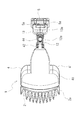
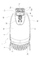
バッテリパック5を図8〜図11に示している。図8はバッテリパック5を接続面側から見た図で、図9はバッテリパック5を取り付け方向や取り外し方向に対して直交する方向である側方から見た図で、図10は図8のB−B断面図で、図11は、バッテリパック5を前側から見た図である。
<Battery pack 5>
The battery pack 5 is shown in FIGS. 8 is a view of the battery pack 5 as seen from the connection surface side, FIG. 9 is a view of the battery pack 5 as seen from the side that is orthogonal to the mounting direction and the detaching direction, and FIG. FIG. 11 is a cross-sectional view taken along line B-B, and FIG. 11 is a view of the battery pack 5 as viewed from the front side.

バッテリパック5は、その上面が前側を向くようにして工具本体1に装着される。バッテリパック5は、工具本体1にスライドさせて着脱する構成となっており、そのスライド方向は、本体側接続面やパック側接続面に沿った方向である。尚、上述した着脱方向がスライド方向となる。バッテリパック5は、全体としてボックス型であって、詳細には着脱方向に沿って長い直方体であり、その上面がパック側接続面となっている。バッテリパック5を図8のようにパック側接続面側から見た時、バッテリパック5は着脱方向に沿って長い長方形であり、図8において、着脱方向が長辺方向となるが、それと直交する短辺方向を幅方向と称する。そして、パック側接続面の法線方向を上下方向とし、その方向の寸法を厚さとすると、バッテリパック5は、着脱方向の寸法や幅方向の寸法に対して厚さが薄い直方体となっている。   The battery pack 5 is mounted on the tool body 1 with its upper surface facing the front side. The battery pack 5 is configured to be attached to and detached from the tool main body 1 and the sliding direction is a direction along the main body side connection surface or the pack side connection surface. In addition, the attachment / detachment direction mentioned above becomes a slide direction. The battery pack 5 is a box type as a whole, and is specifically a rectangular parallelepiped that is long along the attaching / detaching direction, and its upper surface is a pack-side connection surface. When the battery pack 5 is viewed from the pack-side connection surface side as shown in FIG. 8, the battery pack 5 is a rectangle that is long along the attaching / detaching direction. In FIG. 8, the attaching / detaching direction is the long side direction, but is orthogonal thereto. The short side direction is referred to as the width direction. Then, assuming that the normal direction of the pack side connection surface is the vertical direction and the dimension in that direction is the thickness, the battery pack 5 is a rectangular parallelepiped having a small thickness with respect to the dimension in the attaching / detaching direction and the dimension in the width direction. .

バッテリパック5の上面には、周縁部のうち前側及び左右両側の三方に平坦な平面からなるベース面50が形成されており、また、中央部にはベース面50に対して一段上方に突出した高台部51が形成されている。該高台部51の上面51aは平坦面となっている。このベース面50と高台部51の上面51aからパック側接続面が構成されている。尚、ベース面50の後側には、後方に向けて徐々に高くなっていくように傾斜した傾斜面52が形成されている。該傾斜面52は高台部51の上面51aよりも高い位置まで延びている。そして、バッテリパック5の上面の後端部には、ベース面50から後方に延びた傾斜面52を前側の斜面とする山部53が形成されており、高台部51は、この山部53の中腹から前側に向かって水平に延びている。バッテリパック5の厚さは、この山部53の山頂部53aにおいて最も厚くなっている。   On the upper surface of the battery pack 5, a base surface 50 made of a flat surface is formed on the front side and the left and right sides of the peripheral portion, and the center portion protrudes one step above the base surface 50. A hill part 51 is formed. The upper surface 51a of the hill part 51 is a flat surface. A pack-side connection surface is constituted by the base surface 50 and the upper surface 51 a of the hill portion 51. Note that an inclined surface 52 is formed on the rear side of the base surface 50 so as to gradually increase toward the rear. The inclined surface 52 extends to a position higher than the upper surface 51 a of the hill 51. A ridge 53 is formed at the rear end of the upper surface of the battery pack 5 with an inclined surface 52 extending rearward from the base surface 50 as a front slope. It extends horizontally from the middle to the front. The thickness of the battery pack 5 is the thickest at the peak portion 53 a of the peak portion 53.

高台部51の前端部には、工具本体1と電気的に接続するためのパック側端子54が設けられている。該パック側端子54は複数列存在していてバッテリパック5の幅方向に沿って間隔をあけて配されており、本実施形態ではパック側端子54が合計五列配置されているが、そのうちの中央の一列はダミー端子である。パック側端子54には工具本体1の本体側端子24が接続されるが、例えばパック側端子54が雌側とされ、本体側端子24は雄側とされていて、本体側端子24がパック側端子54に着脱方向に沿って挿入される構成とされる。従って、パック側端子54は、前側に開口した形状となっていて、高台部51の前端面に開口している。   A pack-side terminal 54 for electrically connecting to the tool body 1 is provided at the front end portion of the hill portion 51. The pack side terminals 54 exist in a plurality of rows and are arranged at intervals along the width direction of the battery pack 5. In the present embodiment, a total of five rows of pack side terminals 54 are arranged. The central row is a dummy terminal. The main body side terminal 24 of the tool main body 1 is connected to the pack side terminal 54. For example, the pack side terminal 54 is a female side, the main body side terminal 24 is a male side, and the main body side terminal 24 is a pack side. The terminal 54 is configured to be inserted along the attaching / detaching direction. Therefore, the pack-side terminal 54 has a shape opened to the front side, and is open to the front end surface of the hill part 51.

バッテリパック5は工具本体1にスライド装着される構成であるため、工具本体1とバッテリパック5にはそれぞれ互いに係合するスライドレールが着脱方向に沿って形成されている。工具本体1のスライドレールを本体側スライドレール25と称し、バッテリパック5側のスライドレールをパック側スライドレール55と称することにする。本体側スライドレール25とパック側スライドレール55は、着脱方向に沿って延びた形状であって、着脱方向と直交する切断面で切断したとき、図7のように互いに凹凸係合する構成となっている。尚、図7では内部構造を省略している。具体的には、本体側スライドレール25とパック側スライドレール55は、互いにバッテリパック5の幅方向に凹凸係合して、着脱方向に沿って摺動する。   Since the battery pack 5 is slidably mounted on the tool body 1, slide rails that engage with each other are formed on the tool body 1 and the battery pack 5 along the attaching / detaching direction. The slide rail of the tool main body 1 is referred to as a main body side slide rail 25, and the slide rail on the battery pack 5 side is referred to as a pack side slide rail 55. The main body side slide rail 25 and the pack side slide rail 55 have a shape extending along the attaching / detaching direction, and are configured to engage with each other as shown in FIG. 7 when cut along a cutting plane orthogonal to the attaching / detaching direction. ing. In FIG. 7, the internal structure is omitted. Specifically, the main body side slide rail 25 and the pack side slide rail 55 engage with each other in the width direction of the battery pack 5 and slide along the attachment / detachment direction.

本体側スライドレール25とパック側スライドレール55は、それぞれ左右一対形成されている。左右一対の本体側スライドレール25と左右一対のパック側スライドレール55のうち、一方が雄側であって他方が雌側であり、本実施形態では、本体側スライドレール25が雌側であって、パック側スライドレール55が本体側スライドレール25の内側に入り込む雄側である。パック側スライドレール55は、バッテリパック5の高台部51の左右側面に形成されている。詳細には、高台部51の側面下部に着脱方向に沿って凹溝55bが形成され、高台部51の側面上部には、高台部51の側面下部に凹溝55bを形成することによって相対的に側方に突出した状態となった凸条55aが着脱方向に沿って形成されており、この上側の凸条55aと下側の凹溝55bとからパック側スライドレール55が構成されている。尚、左右一対のパック側スライドレール55は互いに対称形状となっている。パック側スライドレール55が形成されている箇所でバッテリパック5をパック側スライドレールを横断するように上下方向に切断すると、高台部50の断面形状は図7のようにT字状となる。   The main body side slide rail 25 and the pack side slide rail 55 are respectively formed in a pair of left and right. Of the pair of left and right main body side slide rails 25 and the pair of left and right pack side slide rails 55, one is a male side and the other is a female side. In this embodiment, the main body side slide rail 25 is a female side. The pack side slide rail 55 is the male side that enters the inside of the main body side slide rail 25. The pack-side slide rail 55 is formed on the left and right side surfaces of the hill part 51 of the battery pack 5. Specifically, a groove 55b is formed in the lower part of the side surface of the hill part 51 along the attaching / detaching direction, and the groove part 55b is relatively formed in the upper part of the side surface of the hill part 51 by forming a groove 55b in the lower part of the side surface of the hill part 51. Convex ridges 55a projecting sideways are formed along the attaching / detaching direction, and the pack-side slide rail 55 is constituted by the upper ridges 55a and the lower concave grooves 55b. The pair of left and right pack side slide rails 55 are symmetrical with each other. When the battery pack 5 is cut in the vertical direction so as to cross the pack-side slide rail at the place where the pack-side slide rail 55 is formed, the cross-sectional shape of the elevated portion 50 becomes a T-shape as shown in FIG.

また、高台部51の上面51aの後部には開口部が形成され、その開口部からロック爪56が上方に突出している。該ロック爪56は、図3(b)に示している工具本体1のロック用凹部26に係脱自在に係合する。具体的には、ロック爪56が工具本体1のロック用凹部26に係合するとバッテリパック5は装着状態にロックされ、ロック爪56が工具本体1のロック用凹部26から外れると、ロック状態が解除されてバッテリパック5を工具本体1から取り外すことができる。ロック爪56は、上下に移動可能に構成されている。ロック爪56が上方に移動して高台部51の上面51aからの突出量が大きくなった状態がロック状態であって工具本体1のロック用凹部26に係合する状態であり、ロック爪56が下方に移動して高台部51の上面51aからの突出量が小さくなった状態がロック解除状態であって工具本体1のロック用凹部26から外れた状態である。図8〜図11はロック爪56がロック状態である場合を示している。尚、ロック爪56はロック状態側に付勢されていて常時はロック状態にある。即ち、ロック爪56は上側に付勢されている。また、ロック爪56の前部には傾斜面が形成されている。また、ロック爪56は、バッテリパック5の幅方向に長い形状とされている。   Further, an opening is formed in the rear part of the upper surface 51a of the hill part 51, and the lock claw 56 projects upward from the opening. The lock claw 56 is detachably engaged with the lock recess 26 of the tool body 1 shown in FIG. Specifically, when the locking claw 56 engages with the locking recess 26 of the tool body 1, the battery pack 5 is locked in the mounted state, and when the locking claw 56 is removed from the locking recess 26 of the tool body 1, the locked state is changed. The battery pack 5 can be removed from the tool body 1 after being released. The lock claw 56 is configured to be movable up and down. The state in which the lock claw 56 moves upward and the amount of protrusion from the upper surface 51a of the hill part 51 is large is the locked state and is engaged with the lock recess 26 of the tool body 1. The state in which the amount of protrusion from the upper surface 51a of the hill part 51 is reduced by moving downward is the unlocked state, and is the state in which it is removed from the locking recess 26 of the tool body 1. 8-11 has shown the case where the lock nail | claw 56 is a locked state. The lock claw 56 is urged toward the locked state and is always in the locked state. That is, the lock claw 56 is biased upward. Further, an inclined surface is formed at the front portion of the lock claw 56. Further, the lock claw 56 has a long shape in the width direction of the battery pack 5.

高台部51の後側には、ロック爪56をロック状態からロック解除状態にするためのロック解除操作部としてのロック解除ボタン57が設けられている。ロック解除ボタン57はバッテリパック5の後端部に位置しており、山部53の後側の斜面に設けられている。該ロック解除ボタン57を下方に向けて押すと、ロック爪56がロック位置からロック解除位置へと下降してロック状態が解除され、ロック解除ボタン57から手を離して押圧力を解放すると、ロック解除ボタン57は元の状態に戻り、それに伴ってロック爪56もロック位置に戻る。ロック解除ボタン57とロック爪56とを連動させるための構成は種々であってよいが、本実施形態ではロック解除ボタン57とロック爪56は一つの部材として一体的に形成されており、この部材が上側に付勢されることでロック爪56がロック位置側に付勢されている。その付勢手段は任意であるが、例えば図示しないバネによってロック解除ボタン57を上側に付勢することができる。   On the rear side of the hill part 51, an unlock button 57 is provided as an unlock operation unit for changing the lock claw 56 from the locked state to the unlocked state. The lock release button 57 is located at the rear end portion of the battery pack 5 and is provided on the slope on the rear side of the mountain portion 53. When the lock release button 57 is pushed downward, the lock claw 56 is lowered from the lock position to the lock release position to release the lock state. When the release force is released by releasing the lock release button 57, the lock is released. The release button 57 returns to the original state, and accordingly, the lock claw 56 also returns to the lock position. There may be various configurations for interlocking the lock release button 57 and the lock claw 56. However, in this embodiment, the lock release button 57 and the lock claw 56 are integrally formed as one member. As a result, the lock claw 56 is biased toward the lock position. The biasing means is arbitrary, but the lock release button 57 can be biased upward by a spring (not shown), for example.

尚、バッテリパック5は、パック側接続面よりも下側に、パック側接続面よりも幅広の電池収容部58を備えており、その収容部に図10のように複数の電池59を内蔵している。バッテリパック5は、電池59を収容すべく中空状のパックハウジング60を備えている。該パックハウジング60は半割状の上下二つのパーツを備えていて、その二つのパーツが互いに接合されて中空状に構成されている。上述した高台部51や山部53は、パックハウジング60を構成している上側のパーツに形成されている。また、パックハウジング60とは別体の構成として可動部材61(図10参照)を備えていて、その可動部材61の一部がロック解除ボタン57やロック爪56として構成されている。   The battery pack 5 includes a battery accommodating portion 58 that is lower than the pack-side connecting surface and wider than the pack-side connecting surface, and a plurality of batteries 59 are incorporated in the accommodating portion as shown in FIG. ing. The battery pack 5 includes a hollow pack housing 60 to accommodate the battery 59. The pack housing 60 includes two upper and lower parts that are halved, and the two parts are joined together to form a hollow shape. The above-described hill part 51 and peak part 53 are formed in the upper part constituting the pack housing 60. Further, a movable member 61 (see FIG. 10) is provided as a separate structure from the pack housing 60, and a part of the movable member 61 is configured as a lock release button 57 and a lock claw 56.

<工具本体1>
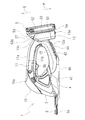
工具本体1を図1〜図7に示しているが、図1、図3(a)、図5及び図7がバッテリパック5を取り付けた状態で、図2、図3(b)及び図6がバッテリパック5を取り外した状態である。工具本体1は、刈り取り対象物である芝を剪断するための剪断刃2と、該剪断刃2を駆動するための駆動部と、中空状の本体ハウジング3と、本体ハウジング3の下側に取り付けられたスライダ4とを備えている。
<Tool body 1>
The tool body 1 is shown in FIGS. 1 to 7, and FIG. 2, FIG. 3 (b) and FIG. 6 with the battery pack 5 attached in FIGS. 1, 3 (a), 5 and 7. Is a state in which the battery pack 5 is removed. The tool body 1 is attached to a shear blade 2 for shearing the lawn that is an object to be cut, a drive unit for driving the shear blade 2, a hollow body housing 3, and a lower side of the body housing 3. The slider 4 is provided.

<剪断刃2>
剪断刃2は、相対的に往復動可能に設けられた二枚の刃から構成されている。具体的には、固定刃と可動刃から構成され、可動刃を固定刃に対して横方向に往復運動させる構成とされたり、二枚の可動刃から構成されて各可動刃を横方向に互いに反対方向に往復運動させる構成とされたりする。尚、剪断刃2の下方には櫛刃状のガイド2aが配置されている。
<Shearing blade 2>
The shearing blade 2 is composed of two blades provided so as to be relatively reciprocable. Specifically, the movable blade is composed of a fixed blade and a movable blade, and the movable blade is reciprocated in the lateral direction with respect to the fixed blade. It may be configured to reciprocate in the opposite direction. A comb blade-shaped guide 2 a is disposed below the shearing blade 2.

<駆動部>
駆動部は、駆動モータ6と、該駆動モータ6の回転を減速させると共に回転運動を左右の往復運動に変換して剪断刃2に駆動力を伝達する駆動伝達部7とを備えている。駆動モータ6はその回転中心が上下方向となり且つその主軸6aが下方を向くようにして配置されている。駆動伝達部7は駆動モータ6の主軸6aと剪断刃2との間に位置しており、従って、駆動モータ6の下側に位置している。駆動モータ6には、駆動モータ6を作動停止させるための駆動スイッチを介してバッテリパック5から電力が供給される。駆動スイッチは、スイッチ本体8aと該スイッチ本体8aをON、OFFさせるためのトリガー8bとを備えている。トリガー8bは、後述する本体ハウジング3のハンドル部11の下面11bに設けられていてその下面11bから下方に突出している。トリガー8bを上方に押すと駆動スイッチがON状態となって駆動モータ6に電力が供給されて駆動モータ6が作動する。トリガー8bは下方に付勢されており、トリガー8bを押す力が解除されるとトリガー8bは元の位置に戻り、駆動スイッチはOFF状態となって駆動モータ6は停止する。尚、本実施形態において、トリガー8bは前側の支軸8cを中心として上下に回動する構成となっている。
<Driver>
The drive unit includes a drive motor 6 and a drive transmission unit 7 that decelerates the rotation of the drive motor 6 and converts the rotational motion into a left and right reciprocating motion to transmit a driving force to the shearing blade 2. The drive motor 6 is disposed such that the center of rotation is in the vertical direction and the main shaft 6a faces downward. The drive transmission unit 7 is located between the main shaft 6 a of the drive motor 6 and the shearing blade 2, and is therefore located below the drive motor 6. Electric power is supplied to the drive motor 6 from the battery pack 5 through a drive switch for stopping the operation of the drive motor 6. The drive switch includes a switch body 8a and a trigger 8b for turning on and off the switch body 8a. The trigger 8b is provided on the lower surface 11b of the handle portion 11 of the main body housing 3 which will be described later, and projects downward from the lower surface 11b. When the trigger 8b is pushed upward, the drive switch is turned on and electric power is supplied to the drive motor 6 to operate the drive motor 6. The trigger 8b is biased downward. When the force pushing the trigger 8b is released, the trigger 8b returns to the original position, the drive switch is turned off, and the drive motor 6 is stopped. In the present embodiment, the trigger 8b is configured to rotate up and down about the front support shaft 8c.

<本体ハウジング3>
本体ハウジング3は、半割状の左右二つのパーツから構成され、この二つのパーツを接合させることにより中空状となる。本体ハウジング3は、前端部に位置するヘッド部10と、該ヘッド部10の上部から後方に延びるハンドル部11と、ヘッド部10の下部から後方に向けて徐々に上方に傾斜しつつ延びる支持アーム部12と、後端部に位置するバッテリ取付部13とを備えている。
<Main body housing 3>
The main body housing 3 is composed of two left and right parts that are halved, and becomes hollow by joining these two parts. The main body housing 3 includes a head portion 10 located at a front end portion, a handle portion 11 extending rearward from the upper portion of the head portion 10, and a support arm extending while gradually tilting upward from the lower portion of the head portion 10 toward the rear. Part 12 and battery mounting part 13 located at the rear end.

ヘッド部10には駆動部が収容されている。ハンドル部11は全体として前後方向に延びる筒状である。該ハンドル部11には、バッテリ取付部13に取り付けられるバッテリパック5と駆動モータ6とを電気的に接続するための図示しない電気ケーブルが収容されており、その電気ケーブルの途中に駆動スイッチが配設されている。従って、駆動スイッチはハンドル部11に収容されている。スイッチ本体8aはその全体がハンドル部11に収容されており、トリガー8bはハンドル部11の下面11bからその後部が下方に突出している。本体ハウジング3の上面は、ヘッド部10の上面に最も高い頂上部10aを有して、そこから後方に向けて徐々に下降する形状となっている。従って、ハンドル部11の上面11aは後方に向けてなだらかに下降している。   The head unit 10 accommodates a drive unit. The handle part 11 has a cylindrical shape extending in the front-rear direction as a whole. The handle portion 11 accommodates an electric cable (not shown) for electrically connecting the battery pack 5 attached to the battery attachment portion 13 and the drive motor 6, and a drive switch is arranged in the middle of the electric cable. It is installed. Therefore, the drive switch is accommodated in the handle portion 11. The entire switch body 8 a is accommodated in the handle portion 11, and the trigger 8 b protrudes downward from the lower surface 11 b of the handle portion 11. The upper surface of the main body housing 3 has a highest apex portion 10a on the upper surface of the head portion 10, and has a shape that gradually descends from there. Accordingly, the upper surface 11a of the handle portion 11 is gently lowered toward the rear.

ハンドル部11の後端部と支持アーム部12の後端部は互いにつながっており、従って、ヘッド部10とハンドル部11と支持アーム部12は全体としてループ状に形成されている。支持アーム部12もハンドル部11と同様に筒状に形成されているが、その中心線は後方に向けて徐々に上昇している。従って、支持アーム部12の下面には後方に向けて上昇する傾斜面が形成されており、該傾斜面にスライダ4が取り付けられている。即ち、支持アーム部12の下面に、スライダ4を本体ハウジング3に取り付けるためのスライダ取付部12aが形成されているが、この構成については更に後述する。   The rear end portion of the handle portion 11 and the rear end portion of the support arm portion 12 are connected to each other. Therefore, the head portion 10, the handle portion 11, and the support arm portion 12 are formed in a loop shape as a whole. The support arm portion 12 is also formed in a cylindrical shape like the handle portion 11, but its center line gradually rises toward the rear. Therefore, an inclined surface that rises rearward is formed on the lower surface of the support arm portion 12, and the slider 4 is attached to the inclined surface. That is, a slider attachment portion 12a for attaching the slider 4 to the main body housing 3 is formed on the lower surface of the support arm portion 12. This configuration will be described later.

本体ハウジング3の後端部にバッテリ取付部13が形成されている。本体ハウジング3の後端部はハンドル部11と支持アーム部12の連結部分であって本体ハウジング3のループ形状の折り返し部分でもある。バッテリ取付部13は、本体ハウジング3の後端部に後方に突出するように形成されている。バッテリ取付部13の上端部はハンドル部11の上面11aの後端部と連続しているが、バッテリ取付部13の下端部は支持アーム部12の後端部よりも下方に突出している。   A battery mounting portion 13 is formed at the rear end portion of the main body housing 3. The rear end portion of the main body housing 3 is a connecting portion between the handle portion 11 and the support arm portion 12 and is also a loop-shaped folded portion of the main body housing 3. The battery attachment portion 13 is formed at the rear end portion of the main body housing 3 so as to protrude rearward. The upper end portion of the battery attachment portion 13 is continuous with the rear end portion of the upper surface 11 a of the handle portion 11, but the lower end portion of the battery attachment portion 13 projects downward from the rear end portion of the support arm portion 12.

バッテリ取付部13は、その後面にバッテリパック5を取り付ける構成となっている。従って、バッテリ取付部13は、バッテリパック5の形状に対応した形状となっていて図3(b)のように後方から見て全体として縦長の直方体形状である。バッテリ取付部13はその後面が本体側接続面となっていて、従って、本体側接続面は後方を向いている。バッテリパック5を装着したとき、本体側接続面とパック側接続面とは互いに対向する関係にある。従って、バッテリパック5の装着時において、バッテリ取付部13の後面とバッテリパック5の上面が対向し、面接触するか、あるいは、若干の隙間を介して対峙する。   The battery attachment portion 13 is configured to attach the battery pack 5 to the rear surface thereof. Accordingly, the battery mounting portion 13 has a shape corresponding to the shape of the battery pack 5 and has a vertically long rectangular parallelepiped shape as viewed from the rear as shown in FIG. The rear surface of the battery attachment portion 13 is a main body side connection surface, and therefore the main body side connection surface faces rearward. When the battery pack 5 is mounted, the main body side connection surface and the pack side connection surface are in a relationship of facing each other. Therefore, when the battery pack 5 is mounted, the rear surface of the battery mounting portion 13 and the upper surface of the battery pack 5 face each other and come into surface contact with each other or face each other through a slight gap.

バッテリパック5は、上部が前側となり下部が後側となる前傾姿勢で工具本体1のバッテリ取付部13に取り付けられる。従って、バッテリ取付部13はバッテリパック5が前傾姿勢で取り付けられるように構成されており、上部が前側となり下部が後側となるように傾斜した本体側接続面を備えている。バッテリパック5は、前傾姿勢の本体側接続面に沿ってスライドしながら着脱されるが、装着時には、上側から斜め後方に向けてスライドする。尚、前傾姿勢とは、バッテリ取付部13や本体側接続面が直立姿勢となる状態から前側に傾倒した姿勢であって、直立状態からの傾斜角度は45度以下である。   The battery pack 5 is attached to the battery attachment portion 13 of the tool body 1 in a forward tilt posture in which the upper part is the front side and the lower part is the rear side. Therefore, the battery mounting portion 13 is configured such that the battery pack 5 is mounted in a forward tilt posture, and includes a main body side connection surface that is inclined so that the upper portion is the front side and the lower portion is the rear side. The battery pack 5 is attached and detached while sliding along the main body-side connection surface in the forward tilted posture, but when attached, the battery pack 5 slides obliquely rearward from the upper side. Note that the forward leaning posture is a posture in which the battery mounting portion 13 and the main body side connection surface are tilted forward from the upright posture, and the tilt angle from the upright state is 45 degrees or less.

バッテリ取付部13の後面は、バッテリパック5の上面の形状に対応した形状となっている。具体的には、図3〜図5のようにバッテリ取付部13の左右方向の寸法、即ち、幅は、バッテリパック5のパック側接続面の幅と略同じになっている。従って、バッテリ取付部13の幅は、バッテリパック5の電池収容部58よりも狭く、従って、バッテリパック5の全幅よりも狭い。一方、バッテリ取付部13の左右方向の寸法は、ハンドル部11の左右方向の寸法や支持アーム部12の左右方向の寸法に比して大きく、従って、バッテリ取付部13は、ハンドル部11の後端部や支持アーム部12の後端部に対して左右両側に突出した幅広形状となっている。   The rear surface of the battery attachment portion 13 has a shape corresponding to the shape of the upper surface of the battery pack 5. Specifically, as shown in FIGS. 3 to 5, the dimension in the left-right direction of the battery mounting portion 13, that is, the width is substantially the same as the width of the pack-side connection surface of the battery pack 5. Therefore, the width of the battery mounting portion 13 is narrower than the battery accommodating portion 58 of the battery pack 5, and thus is narrower than the entire width of the battery pack 5. On the other hand, the left and right dimensions of the battery mounting portion 13 are larger than the left and right dimensions of the handle portion 11 and the left and right dimensions of the support arm portion 12. It has a wide shape projecting to the left and right sides with respect to the end portion and the rear end portion of the support arm portion 12.

バッテリ取付部13の後面には、バッテリパック5の高台部51の上面51aと対向する面である取り付け基準面20が形成されている。該取り付け基準面20は前傾姿勢の傾斜平面である。取り付け基準面20の左右両側部と下端部には周壁部が突設されている。即ち、周壁部は、取り付け基準面20の上端部を除く三方に形成されていて、左右一対の横壁部21と下壁部22とから構成されて、上方に開口した全体としてコの字状に形成されている。周壁部のうち取り付け基準面20から最も離れた面である周壁部の後端面23は、前傾姿勢の傾斜平面となっていて、取り付け基準面20とは平行関係にある。該周壁部の後端面23は、バッテリパック5のベース面50と対向する。この取り付け基準面20と周壁部の後端面23とから本体側接続面が構成されている。   On the rear surface of the battery mounting portion 13, a mounting reference surface 20 that is a surface facing the upper surface 51 a of the hill portion 51 of the battery pack 5 is formed. The attachment reference plane 20 is an inclined plane in a forward inclined posture. Peripheral wall portions project from the left and right side portions and the lower end portion of the mounting reference surface 20. That is, the peripheral wall portion is formed on three sides excluding the upper end portion of the attachment reference surface 20 and is composed of a pair of left and right lateral wall portions 21 and a lower wall portion 22, and has an overall U-shape that opens upward. Is formed. The rear end surface 23 of the peripheral wall portion, which is the surface farthest from the attachment reference surface 20 among the peripheral wall portions, is an inclined plane in a forward inclined posture, and is in parallel with the attachment reference surface 20. The rear end surface 23 of the peripheral wall portion faces the base surface 50 of the battery pack 5. A main body side connection surface is constituted by the attachment reference surface 20 and the rear end surface 23 of the peripheral wall portion.

取り付け基準面20の下端部であって下壁部22の上側の位置に本体側端子24が配設されている。バッテリパック5はバッテリ取付部13に上方から下方に向けてスライドさせて装着されるため、本体側端子24は上方に向かって延びている。本体側端子24はバッテリ取付部13の幅方向に沿って間隔をあけながら複数配置されていて、本実施形態では合計四列配置されている。   A main body side terminal 24 is disposed at a lower end portion of the attachment reference surface 20 and above the lower wall portion 22. Since the battery pack 5 is mounted on the battery mounting portion 13 by sliding downward from above, the main body side terminal 24 extends upward. A plurality of main body side terminals 24 are arranged at intervals along the width direction of the battery mounting portion 13, and a total of four rows are arranged in this embodiment.

両横壁部21の内側の側面にぞれぞれ本体側スライドレール25が形成されている。詳細には、横壁部21の内側の側面において、取り付け基準面20に近い側である前部に着脱方向に沿って即ち前傾の方向に沿って凹溝25bが形成され、取り付け基準面20から遠い側である後部に凹溝25bを形成することによって相対的に内側に突出した状態となった凸条25aが着脱方向に沿って形成されており、これらの前側の凹溝25bと後側の凸条25aとから本体側スライドレール25が構成されている。尚、左右一対の本体側スライドレール25は互いに対称形状となっている。そして、図7のようにバッテリパック5の装着状態において、バッテリパック5の高台部51の左右外側に両横壁部21が位置する。換言すれば、左右一対の本体側スライドレール25の内側にパック側スライドレール55が挿入される状態となり、パック側スライドレール55は左右一対の本体側スライドレール25によって左右両側から抱きかかえられる状態となる。そして、本体側スライドレール25の凹溝25bとパック側スライドレール55の凸条55aが凹凸係合し、本体側スライドレール25の凸条25aとパック側スライドレール55の凹溝55bが凹凸係合する。   A main body side slide rail 25 is formed on each of the inner side surfaces of both lateral wall portions 21. Specifically, on the inner side surface of the lateral wall portion 21, a concave groove 25 b is formed along the attachment / detachment direction, that is, along the forward tilt direction, in the front portion that is closer to the attachment reference surface 20. Convex ridges 25a that are relatively protruded inward by forming concave grooves 25b in the rear part that is on the far side are formed along the attaching / detaching direction, and these front concave grooves 25b and rear side grooves 25b The main body side slide rail 25 is comprised from the protruding item | line 25a. The pair of left and right main body side slide rails 25 are symmetrical to each other. Then, in the state where the battery pack 5 is mounted as shown in FIG. In other words, the pack-side slide rail 55 is inserted inside the pair of left and right body-side slide rails 25, and the pack-side slide rail 55 is held by the pair of left and right body-side slide rails 25 from both the left and right sides. Become. Then, the concave groove 25b of the main body side slide rail 25 and the convex stripe 55a of the pack side slide rail 55 are engaged with each other, and the convex stripe 25a of the main body side slide rail 25 and the concave groove 55b of the pack side slide rail 55 are unevenly engaged. To do.

取り付け基準面20の上側にはロック用凹部26が形成されている。ロック用凹部26はロック爪56に対応した形状とされる。ロック爪56がバッテリパック5の幅方向に長い形状であるため、ロック用凹部26もそれに対応して左右方向に長い形状とされ、具体的には、左右方向に沿って延びる溝状に形成されている。尚、ロック用凹部26は、横壁部21の上端の直ぐ上側に位置している。   A locking recess 26 is formed on the upper side of the attachment reference surface 20. The locking recess 26 has a shape corresponding to the locking claw 56. Since the lock claw 56 has a shape that is long in the width direction of the battery pack 5, the lock recess 26 has a correspondingly long shape in the left-right direction, and is specifically formed in a groove shape extending in the left-right direction. ing. The locking recess 26 is located immediately above the upper end of the lateral wall portion 21.

また、横壁部21の後端面23の上側にはバッテリパック5の山部53の傾斜面52に対応して装着時に山部53の傾斜面52と対向する導入面27が形成されている。該導入面27は、横壁部21の後端面23と連続しているがそれよりも幅狭である。また、横壁部21の後端面23が直立姿勢に対して所定角度前側に傾斜しているが、それよりも更に前側に傾倒するように傾斜している。   An introduction surface 27 is formed on the upper side of the rear end surface 23 of the horizontal wall portion 21 so as to face the inclined surface 52 of the peak portion 53 when mounted, corresponding to the inclined surface 52 of the peak portion 53 of the battery pack 5. The introduction surface 27 is continuous with the rear end surface 23 of the lateral wall portion 21, but is narrower than that. Further, the rear end surface 23 of the horizontal wall portion 21 is inclined to the front side by a predetermined angle with respect to the upright posture, but is inclined so as to be inclined further to the front side.

尚、バッテリ取付部13の上端部にはバッテリパック5の山部53の山頂部53aが位置するが、そのバッテリ取付部13の上端部の高さはハンドル部11の上面11aの後端部の高さと略同じである。従って、ハンドル部11の上面11aから導入面27を介してバッテリ取付部13の周壁部の後端面23まで徐々に後側に向かって低くなっている。尚、本実施形態では、ハンドル部11の上面11aの高さはその後端部において最も低くなっており、従って、ハンドル部11の上面11aのうち最も高さが低い最下部11cはハンドル部11の上面11aの後端部に位置しているが、最下部11cから更に後側に向けて若干高さが上昇した後にバッテリ取付部13の導入面27が連設する構成であってもよい。但し、ハンドル部11の上面11aの最下部11cよりも、少なくともバッテリ取付部13の本体側接続面の上端(図2及び図6において符号23aで示す箇所)の方が低くなるようにすることが好ましい。   In addition, although the peak part 53a of the peak part 53 of the battery pack 5 is located in the upper end part of the battery attachment part 13, the height of the upper end part of the battery attachment part 13 is the rear end part of the upper surface 11a of the handle part 11. It is almost the same as the height. Accordingly, the height gradually decreases from the upper surface 11 a of the handle portion 11 to the rear end surface 23 of the peripheral wall portion of the battery mounting portion 13 through the introduction surface 27 toward the rear side. In the present embodiment, the height of the upper surface 11a of the handle portion 11 is the lowest at the rear end portion, and therefore the lowest lowermost portion 11c of the upper surface 11a of the handle portion 11 is the lowest of the handle portion 11. Although it is located at the rear end portion of the upper surface 11a, the introduction surface 27 of the battery mounting portion 13 may be continuously provided after the height slightly rises further toward the rear side from the lowermost portion 11c. However, the lower end 11c of the upper surface 11a of the handle portion 11 should be lower at least at the upper end of the battery-side connection surface of the battery mounting portion 13 (the portion indicated by reference numeral 23a in FIGS. 2 and 6). preferable.

また、バッテリ取付部13は、支持アーム部12の後端部から下方に所定量突出しているが、図1に示すようにバッテリパック5を装着した状態において、バッテリパック5のうち最も低い部分である最下部5aは、本体側接続面である周壁部の後端面23よりも下方に所定量突出する。具体的には、装着状態におけるバッテリパック5の最下部5aは、即ち、図8に示す取付前の単体の状態におけるバッテリパック5の着脱方向の前端部であるが、そのバッテリパック5の着脱方向の前端部はベース面50から前側に所定量突出している。そして、バッテリパック5のベース面50は、装着状態においてバッテリ取付部13の周壁部の後端面23と一致する。従って、バッテリパック5を工具本体1に取り付けると、バッテリパック5の最下部5aが周壁部の後端面23から所定量下方に突出することになる。その一方、バッテリ取付部13は前傾姿勢となっていて、その下端面の前端部、あるいは、パックハウジング60のパーツ同士をネジ止めするためのボス部がバッテリパック5の着脱方向の前端部に設けられている場合にはそのボス部がバッテリ取付部13において最も低い部分である最下部13aとなるが、バッテリ取付部13の最下部13aに対してバッテリパック5の最下部5aは同じ高さであるか、あるいは、それ以上の高さとなっている。従って、バッテリパック5は、装着時においてバッテリ取付部13よりも下方には突出しない。   Further, the battery mounting portion 13 protrudes downward by a predetermined amount from the rear end portion of the support arm portion 12, but in the state where the battery pack 5 is mounted as shown in FIG. A certain lowermost part 5a protrudes a predetermined amount below the rear end face 23 of the peripheral wall part which is the main body side connection surface. Specifically, the lowermost part 5a of the battery pack 5 in the mounted state is the front end portion of the battery pack 5 in the mounting / detaching direction in the single state before mounting shown in FIG. The front end portion of the base plate protrudes from the base surface 50 by a predetermined amount. The base surface 50 of the battery pack 5 coincides with the rear end surface 23 of the peripheral wall portion of the battery mounting portion 13 in the mounted state. Therefore, when the battery pack 5 is attached to the tool body 1, the lowermost portion 5a of the battery pack 5 protrudes downward from the rear end face 23 of the peripheral wall portion by a predetermined amount. On the other hand, the battery mounting portion 13 is inclined forward, and the front end portion of the lower end surface thereof, or the boss portion for screwing the parts of the pack housing 60 to each other at the front end portion of the battery pack 5 in the attaching / detaching direction. In the case where the battery mounting portion 13 is provided, the boss portion is the lowest portion 13a which is the lowest portion of the battery mounting portion 13, but the lowermost portion 5a of the battery pack 5 is the same height as the lowermost portion 13a of the battery mounting portion 13. Or higher than that. Therefore, the battery pack 5 does not protrude downward from the battery mounting portion 13 when mounted.

<スライダ4>
スライダ4は、その底面に平坦な平面である摺動面40を有していて、芝刈り時にその摺動面40が芝の上を滑る。従って、スライダ4の摺動面40は、芝刈り機を地面に載置する際の設置面であり、芝刈り作業においては芝を刈る高さを決める刈り取り基準面となり、摺動面40に対する剪断刃2の高さが芝の刈り取り高さとなる。本実施形態ではスライダ4が高さ調節可能に構成され、その構成によって芝の刈り取り高さを調節できる。スライダ4の高さ調節の構成は種々であってよいが、本実施形態では、スライダ4の本体ハウジング3への取り付け高さを変更することでスライダ4の高さが変更できる構成とされている。具体的には、スライダ4は上述の摺動面40を有する幅広の主部41と、該主部41の後端部から後方に向けて延びる幅狭の取付片部42とを有している。主部41は、図1及び図2のように本体ハウジング3のヘッド部10から支持アーム部12の前部の下側をカバーする。取付片部42は図4及び図5のように主部41よりも幅狭に形成されていて支持アーム部12の下側に位置する。取付片部42は支持アーム部12の下面に沿って後方且つ上方に向けて傾斜しつつ延びている。尚、取付片部42は支持アーム部12よりも幅狭である。取付片部42は支持アーム部12の下面に形成された傾斜面からなるスライダ取付部12aに対向してそれに取り付けられると共に、スライダ取付部12aの傾斜に沿ってスライドさせることができる。即ち、取付片部42にスライダ4の高さを調節するための高さ調節機構部が設けられており、スライダ4の取付位置を最も後側にするとスライダ4の高さは最も高い状態となって芝を短く刈り取ることになる。一方、スライダ4の取付位置を最も前側にするとスライダ4の高さが最も低くなって刈り取られた後の芝の長さは長くなる。このようにスライダ4を傾斜面52であるスライダ取付部12aに沿って前後に移動させることでスライダ4を上下にも移動させることができてその高さを調節することができる。図1〜図6はスライダ4を最も上側且つ後側に位置させた状態を示している。尚、スライダ4は、取付片部42の押圧部44を上方に押すことで固定状態が解除されてスライド可能となり、押圧部44への押圧を停止すると固定状態となる。
<Slider 4>
The slider 4 has a sliding surface 40 which is a flat plane on the bottom surface, and the sliding surface 40 slides on the grass when mowing the lawn. Therefore, the sliding surface 40 of the slider 4 is an installation surface when the lawn mower is placed on the ground, and becomes a cutting reference plane that determines the height of the lawn mowing in the lawn mowing work. The height of the blade 2 is the grass cutting height. In this embodiment, the slider 4 is configured to be adjustable in height, and the height of lawn cutting can be adjusted by the configuration. The configuration for adjusting the height of the slider 4 may be various, but in this embodiment, the height of the slider 4 can be changed by changing the mounting height of the slider 4 to the main body housing 3. . Specifically, the slider 4 has a wide main portion 41 having the above-described sliding surface 40 and a narrow attachment piece portion 42 extending rearward from the rear end portion of the main portion 41. . The main portion 41 covers the lower side of the front portion of the support arm portion 12 from the head portion 10 of the main body housing 3 as shown in FIGS. 1 and 2. As shown in FIGS. 4 and 5, the attachment piece portion 42 is formed narrower than the main portion 41 and is positioned below the support arm portion 12. The attachment piece 42 extends while being inclined rearward and upward along the lower surface of the support arm portion 12. The attachment piece portion 42 is narrower than the support arm portion 12. The attachment piece 42 is attached to and opposed to the slider attachment portion 12a formed of an inclined surface formed on the lower surface of the support arm portion 12, and can be slid along the inclination of the slider attachment portion 12a. That is, the mounting piece 42 is provided with a height adjusting mechanism for adjusting the height of the slider 4. When the mounting position of the slider 4 is at the rearmost position, the height of the slider 4 is the highest. The grass will be cut short. On the other hand, when the mounting position of the slider 4 is set to the foremost side, the height of the slider 4 becomes the lowest and the length of the lawn after cutting is increased. Thus, by moving the slider 4 back and forth along the slider mounting portion 12a which is the inclined surface 52, the slider 4 can be moved up and down and its height can be adjusted. 1 to 6 show a state in which the slider 4 is positioned on the uppermost side and the rear side. The slider 4 can be slid by releasing the fixed state by pressing the pressing portion 44 of the attachment piece portion 42 upward, and is fixed when the pressing to the pressing portion 44 is stopped.

以上のように構成された芝刈り機においては、図1に矢印Pで示している方向に沿ってバッテリパック5をバッテリ取付部13にスライド装着させることができる。バッテリパック5とバッテリ取付部13にはそれぞれパック側スライドレール55と本体側スライドレール25が設けられているので、バッテリパック5をスムーズ且つ確実にスライド装着できて、本体側端子24にパック側端子54が確実に接続される。このようにバッテリパック5を装着する際には、バッテリ取付部13の本体側接続面が前側に傾斜しているので、上方から本体側接続面や本体側スライドレール25を容易に視認できる。従って、バッテリパック5を容易且つ確実に取り付けることができる。また、バッテリパック5を上方から下方に向けてスライド装着する構成であるので、バッテリパック5を下方から上方に向けてスライド装着する構成に比して装着作業が容易になる。   In the lawn mower configured as described above, the battery pack 5 can be slid and mounted on the battery mounting portion 13 along the direction indicated by the arrow P in FIG. Since the battery pack 5 and the battery mounting portion 13 are provided with the pack side slide rail 55 and the main body side slide rail 25, respectively, the battery pack 5 can be slid smoothly and reliably, and the main body side terminal 24 is connected to the pack side terminal. 54 is securely connected. Thus, when the battery pack 5 is mounted, since the main body side connection surface of the battery mounting portion 13 is inclined forward, the main body side connection surface and the main body side slide rail 25 can be easily visually recognized from above. Therefore, the battery pack 5 can be easily and reliably attached. Further, since the battery pack 5 is configured to be slid and mounted from the top to the bottom, the mounting operation is facilitated as compared with the configuration in which the battery pack 5 is slid and mounted from the bottom to the top.

そして、バッテリパック5を所定位置までスライドさせると、バッテリパック5のロック爪56がバッテリ取付部13のロック用凹部26に係合して、バッテリパック5が所定位置にロックされる。従って、バッテリパック5が工具本体1から不用意に外れることがない。逆に、バッテリパック5を工具本体1から取り外す際には、ロック解除ボタン57を押しながらバッテリパック5を引き上げるように矢印Qで示している方向に沿ってスライドさせればよく、簡単に取り外すことができる。   When the battery pack 5 is slid to a predetermined position, the lock claw 56 of the battery pack 5 engages with the locking recess 26 of the battery mounting portion 13 and the battery pack 5 is locked at the predetermined position. Therefore, the battery pack 5 is not inadvertently detached from the tool body 1. Conversely, when removing the battery pack 5 from the tool body 1, the battery pack 5 may be slid along the direction indicated by the arrow Q so as to pull up the battery pack 5 while pressing the lock release button 57. Can do.

バッテリパック5を装着した状態では、バッテリパック5は前傾姿勢となるので、重量物であるバッテリパック5が後端部に位置していても尻上がりの状態には見えにくくなり、見た目の安定感が出る。従って、芝刈り作業を行うにあたって使用者は無意識のうちにあるいは意識的に力が入り過ぎるということがなく、楽に作業を行うことができる。手持ち式の電動工具では特にこのような見た目の安定感が使用者の心理に少なからず影響を及ぼすので、バッテリパック5が前傾姿勢で取り付けられることによって安定感のある見た目が得られることのメリットは大きい。特に、ハンドル部11の上面11aからバッテリ取付部13の本体側接続面に向けて徐々に下降しているので、バッテリパック5の取付位置が下がると共に見た目の安定感もより一層増すことになり、作業中の不要な力もより一層入りにくくなって作業負担が軽減される。   When the battery pack 5 is mounted, the battery pack 5 is tilted forward, so that even if the heavy battery pack 5 is located at the rear end, it is difficult to see the upside-down state and the appearance is stable. coming out. Therefore, the user can perform the work comfortably without unconsciously or consciously applying too much force when performing the lawn mowing work. Especially with hand-held power tools, this kind of visual stability has a considerable impact on the user's psychology, so the battery pack 5 can be mounted in a forward-tilting position to provide a stable appearance. Is big. In particular, since it gradually descends from the upper surface 11a of the handle portion 11 toward the connection surface on the main body side of the battery mounting portion 13, the mounting position of the battery pack 5 is lowered and the visual stability is further increased. Unnecessary force during work is further difficult to enter, and the work load is reduced.

また、取付状態において、バッテリパック5の最下部5aが本体側接続面から下方に所定量突出すると共に、バッテリパック5の最下部5aがバッテリ取付部13の最下部13aよりも下側には位置しないようにすると、バッテリパック5の取付位置を下げることができて見た目の安定感が増すと共に重心も下げることができる。しかも、バッテリパック5の最下部5aが下方に突出し過ぎることもないので、バッテリパック5の最下部5aが地面等に接触することも防止できる。   In the mounted state, the lowermost part 5a of the battery pack 5 protrudes downward by a predetermined amount from the main body-side connection surface, and the lowermost part 5a of the battery pack 5 is positioned below the lowermost part 13a of the battery mounting part 13. If not, the attachment position of the battery pack 5 can be lowered, and the visual stability can be increased and the center of gravity can be lowered. Moreover, since the lowermost part 5a of the battery pack 5 does not protrude too much downward, the lowermost part 5a of the battery pack 5 can be prevented from coming into contact with the ground or the like.

尚、厚さの異なる複数種類のバッテリパック5が存在する場合がある。特に、長時間の使用を可能にするためにバッテリパック5を高容量化していくとバッテリパック5の厚さ、特に電池収容部58の厚さはそれに伴って厚くなっていく。そのように厚いバッテリパック5を取り付けたとしても前傾姿勢で取り付けられる構成であるため、薄いバッテリパック5と同様に地面にバッテリパック5が接触するおそれがない。従って、安心して厚いバッテリパック5を取り付けて使用することができる。   There may be a plurality of types of battery packs 5 having different thicknesses. In particular, when the capacity of the battery pack 5 is increased in order to enable long-term use, the thickness of the battery pack 5, particularly the thickness of the battery housing portion 58, increases accordingly. Even if such a thick battery pack 5 is attached, the battery pack 5 is attached in a forward tilted posture, and therefore, there is no possibility that the battery pack 5 contacts the ground as in the case of the thin battery pack 5. Therefore, the thick battery pack 5 can be attached and used with peace of mind.

尚、スライダ4の構成は種々であってよく、例えば、図12〜図14のように後方に延びた大型のスライダ4であってもよい。スライダ4は、支持アーム部12を後側に越えてバッテリ取付部13の位置まで達しており、特に、スライダ4の摺動面40がバッテリ取付部13の位置まで延びている。図14のようにスライダ4の後端部には、バッテリ取付部13との干渉を回避するための逃げ部45が形成されている。該逃げ部45は、スライダ4の後端部の左右方向中央部に形成されていてその左右両側の部分に比して前側に凹んだ形状となっている。即ち、スライダ4の後端部の左右方向中央部には前側に凹んだ逃げ部45が形成され、その左右両側の位置まで摺動面40が延びている。   The configuration of the slider 4 may be various. For example, the slider 4 may be a large slider 4 extending rearward as shown in FIGS. The slider 4 extends beyond the support arm portion 12 to the rear side and reaches the position of the battery mounting portion 13. In particular, the sliding surface 40 of the slider 4 extends to the position of the battery mounting portion 13. As shown in FIG. 14, an escape portion 45 for avoiding interference with the battery attachment portion 13 is formed at the rear end portion of the slider 4. The escape portion 45 is formed at the center in the left-right direction at the rear end of the slider 4 and has a shape recessed toward the front as compared with the left and right sides. That is, a clearance 45 that is recessed forward is formed at the center in the left-right direction at the rear end of the slider 4, and the sliding surface 40 extends to positions on both the left and right sides.

より詳細には、スライダ4の主部41の後部は左右に二股状に分岐して後方に向けて延びていてその二股状部46がバッテリ取付部13の下方であって且つ左右両側の位置まで延びている。このように主部41の後部に二股状部46が延設されることに伴って摺動面40も二股状に延びている。そして、その二股状部46の間に取付片部42が二股状部46との間に間隔をあけることなく一体的に連設されている。二股状部46が摺動面40を有して水平に延びているのに対して取付片部42は支持アーム部12の傾斜に合わせて後方に向けて徐々に上昇している。そして、取付片部42にスライダ4の高さを調節するための高さ調節機構部が設けられている。この実施形態では、ダイヤル47を左右に回転させることで固定状態と固定解除状態に切り替えて高さ調節する構成となっており、ダイヤル47を一方に所定角度回転させると固定解除状態となってスライダ4をスライダ取付部12aの傾斜に沿って前後且つ上下に移動させることができ、ダイヤル47を他方に所定角度回転させると固定状態となってスライダ4をその位置に固定することができる。図12〜図14はスライダ4を最も上側且つ後側に位置させた状態を示している。   More specifically, the rear portion of the main portion 41 of the slider 4 is bifurcated to the left and right and extends rearward, and the bifurcated portion 46 is below the battery mounting portion 13 and to the left and right positions. It extends. As the bifurcated portion 46 extends in the rear portion of the main portion 41 in this way, the sliding surface 40 also extends in a bifurcated shape. The attachment piece 42 is integrally connected between the bifurcated portion 46 with no space between the bifurcated portion 46. The bifurcated portion 46 has a sliding surface 40 and extends horizontally, whereas the attachment piece portion 42 gradually rises rearward in accordance with the inclination of the support arm portion 12. The mounting piece 42 is provided with a height adjusting mechanism for adjusting the height of the slider 4. In this embodiment, the dial 47 is rotated left and right to switch between a fixed state and a fixed release state, and the height is adjusted. When the dial 47 is rotated to a predetermined angle, the fixed release state is set. 4 can be moved back and forth and up and down along the inclination of the slider mounting portion 12a. When the dial 47 is rotated to the other side by a predetermined angle, the slider 4 can be fixed and fixed at that position. 12 to 14 show a state in which the slider 4 is positioned on the uppermost side and the rear side.

このようにスライダ4を最も上側且つ後側に位置させてもスライダ4の後端部に逃げ部45が形成されているので、スライダ4とバッテリ取付部13との干渉を回避することができ、また、ダイヤル47の回転操作の際もバッテリ取付部13が邪魔になりにくい。そして、バッテリ取付部13の下方であってその左右両側の位置まで摺動面40が後方に延びていることにより、芝刈り機の姿勢が安定して前後に揺動しにくくなり、芝刈り高さを一定に保つことができる。しかも、重量物であるバッテリパック5をスライダ4と干渉することなく下げることができ、重心を下げることができる。尚、図12〜図14に示しているように工具本体1の前端部にワイヤーガード9を備えてもよい。尚、スライダ4の周縁部に上方に立設する立ち壁部を形成する場合には、その立ち壁部の一部を下方に切り欠く等して逃げ部45を形成してもよい。   Thus, even if the slider 4 is positioned on the uppermost side and the rear side, the escape portion 45 is formed at the rear end portion of the slider 4, so that interference between the slider 4 and the battery mounting portion 13 can be avoided. In addition, the battery mounting portion 13 is not obstructive even when the dial 47 is rotated. Since the sliding surface 40 extends rearward to the positions on the left and right sides below the battery mounting portion 13, the lawn mower becomes stable in posture and hardly swings back and forth. Can be kept constant. Moreover, the heavy battery pack 5 can be lowered without interfering with the slider 4, and the center of gravity can be lowered. In addition, you may provide the wire guard 9 in the front-end part of the tool main body 1 as shown in FIGS. In addition, when forming the standing wall part standing upright on the peripheral part of the slider 4, you may form the escape part 45 by notching a part of the standing wall part below.

また、図15及び図16に示しているようにバッテリパック5を下方から上方に向けて装着し、下方に取り外す構成であってもよい。更に、バッテリパック5を左右方向に着脱する構成であってもよい。何れにしても、本体側接続面に沿ってバッテリパック5をスライドさせる構成とすることによりバッテリパック5を容易に着脱できる。但し、バッテリパック5をスライド装着させる構成以外の構成であってもよく、装着状態においてバッテリパック5が前傾姿勢であればよい。   Moreover, as shown in FIG.15 and FIG.16, the structure which attaches the battery pack 5 toward the upper direction from the downward direction, and removes it below may be sufficient. Furthermore, the structure which attaches / detaches the battery pack 5 to the left-right direction may be sufficient. In any case, the battery pack 5 can be easily attached and detached by adopting a configuration in which the battery pack 5 is slid along the connection surface on the main body side. However, a configuration other than the configuration in which the battery pack 5 is slidably mounted may be used, and the battery pack 5 only needs to be tilted forward in the mounted state.

また更に、プレート状のスライダ4を採用した構成について説明したが、スライダ4の構成は任意であって例えばワイヤーから構成したものであってもよい。例えば、ワイヤーを所定形状に屈曲させたり湾曲させたりしてスライダ4を構成して、仮想的に刈り取り基準面あるいは設置面を形成してもよい。このようにワイヤーからなるスライダ4であってもその後端部に逃げ部45を形成することは有効である。   Furthermore, although the structure which employ | adopted the plate-shaped slider 4 was demonstrated, the structure of the slider 4 is arbitrary and may be comprised from the wire, for example. For example, the slider 4 may be configured by bending or curving a wire into a predetermined shape, and a virtual cutting reference surface or installation surface may be formed. In this way, it is effective to form the escape portion 45 at the rear end portion of the slider 4 made of wire.

尚、上記実施形態では、芝刈り機(芝生バリカン)について説明したが、生垣バリカン(ヘッジトリマー)であってもよい。また、これらの園芸用剪断電動工具に適しているが、それ以外の電動工具であってもよい。   Although the lawn mower (lawn clipper) has been described in the above embodiment, a hedge clipper (hedge trimmer) may be used. Moreover, although suitable for these gardening shearing electric tools, other electric tools may be used.

1 工具本体
2 剪断刃
2a ガイド
3 本体ハウジング
4 スライダ
5 バッテリパック
5a 最下部
6 駆動モータ
6a 主軸
7 駆動伝達部
8a スイッチ本体
8b トリガー
8c 支軸
9 ワイヤーガード
10 ヘッド部
10a 頂上部
11 ハンドル部
11a 上面
11b 下面
11c 最下部
12 支持アーム部
12a スライダ取付部
13 バッテリ取付部
13a 最下部
20 取り付け基準面(本体側接続面)
21 横壁部
22 下壁部
23 後端面(本体側接続面)
23a 本体側接続面の上端
24 本体側端子
25 本体側スライドレール
25a 凸条
25b 凹溝
26 ロック用凹部
27 導入面
40 摺動面
41 主部
42 取付片部
44 押圧部
45 逃げ部
46 二股状部
47 ダイヤル
50 ベース面(パック側接続面)
51 高台部
51a 上面(パック側接続面)
52 傾斜面
53 山部
53a 山頂部
54 パック側端子
55 パック側スライドレール
55a 凸条
55b 凹溝
56 ロック爪
57 ロック解除ボタン
58 電池収容部
59 電池
60 パックハウジング
61 可動部材
P 取り付け方向
Q 取り外し方向
DESCRIPTION OF SYMBOLS 1 Tool main body 2 Shear blade 2a Guide 3 Main body housing 4 Slider 5 Battery pack 5a Bottom 6 Drive motor 6a Main shaft 7 Drive transmission part 8a Switch main body 8b Trigger 8c Spindle 9 Wire guard 10 Head part 10a Top part 11 Handle part 11a Upper surface 11b Lower surface 11c Lowermost part 12 Support arm part 12a Slider attachment part 13 Battery attachment part 13a Lowermost part 20 Reference mounting surface (main body side connection surface)
21 Horizontal wall portion 22 Lower wall portion 23 Rear end surface (main body side connection surface)
23a Upper end 24 of main body side connection surface Main body side terminal 25 Main body side slide rail 25a Convex strip 25b Concave groove 26 Locking concave portion 27 Introduction surface 40 Sliding surface 41 Main portion 42 Mounting piece portion 44 Pressing portion 45 Escape portion 46 Forked portion 47 Dial 50 Base surface (Pack side connection surface)
51 Upper part 51a Upper surface (pack side connection surface)
52 inclined surface 53 peak portion 53a peak portion 54 pack side terminal 55 pack side slide rail 55a ridge 55b groove 46 lock claw 57 lock release button 58 battery housing portion 59 battery 60 pack housing 61 movable member P mounting direction Q removal direction

Claims (3)

工具本体の後端部に、充電式のバッテリパックを着脱自在に取り付けるためのバッテリ取付部を備えた手持ち式の充電式電動工具であって、
バッテリ取付部は、上部が前側となり下部が後側となるように傾斜した本体側接続面を有し、バッテリパックは本体側接続面に沿ってスライドさせて取り付けられ、
工具本体は、駆動部を有するヘッド部と、該ヘッド部の上部から後方に延びるハンドル部と、ヘッド部の下部から後方に向けて徐々に上方に傾斜しつつ延びてハンドル部の後端部とつながる支持アーム部とを備え、
バッテリ取付部は、支持アーム部の後端部から下方に所定量突出しており、
バッテリパックは、下方に向けてスライド装着される構成であって、取付状態において、バッテリパックの下端部は、本体側接続面から下方に所定量突出する一方バッテリ取付部の下端部以上の高さ位置にあることを特徴とする手持ち式の充電式電動工具。
A hand-held rechargeable electric tool provided with a battery attachment part for detachably attaching a rechargeable battery pack to the rear end of the tool body,
The battery mounting portion has a main body side connection surface that is inclined so that the upper part is the front side and the lower part is the rear side, and the battery pack is attached by sliding along the main body side connection surface,
The tool body includes a head portion having a drive portion, a handle portion extending rearward from the upper portion of the head portion, and a rear end portion of the handle portion extending while gradually tilting upward from the lower portion of the head portion toward the rear. A connecting support arm part,
The battery mounting portion protrudes downward by a predetermined amount from the rear end portion of the support arm portion,
The battery pack is configured to be slid and mounted downward, and in the mounted state, the lower end portion of the battery pack protrudes downward by a predetermined amount from the connection surface on the main body side, and is higher than the lower end portion of the battery mounting portion Hand-held rechargeable power tool characterized by being in position .
ハンドル部の上面からバッテリ取付部の本体側接続面に向けて徐々に下降している請求項記載の手持ち式の充電式電動工具。 The handheld rechargeable electric tool according to claim 1 , wherein the handheld rechargeable electric tool is gradually lowered from the upper surface of the handle portion toward the main body side connection surface of the battery mounting portion. 充電式電動工具は充電式芝刈り機であって、工具本体の下部にスライダを備え、該スライダはバッテリ取付部の位置まで後方に延びており、該スライダの後端部には、バッテリ取付部又はバッテリパックとの干渉を回避するための逃げ部が形成されている請求項1又は2記載の手持ち式の充電式電動工具。 The rechargeable electric tool is a rechargeable lawn mower, and includes a slider at the bottom of the tool body, the slider extending rearward to the position of the battery mounting portion, and the battery mounting portion at the rear end of the slider. Or the escape part for avoiding interference with a battery pack is formed, The hand-held rechargeable electric tool of Claim 1 or 2 .
JP2015132804A 2015-07-01 2015-07-01 Handheld rechargeable power tool Active JP6568415B2 (en)

Priority Applications (1)

Application Number Priority Date Filing Date Title
JP2015132804A JP6568415B2 (en) 2015-07-01 2015-07-01 Handheld rechargeable power tool

Applications Claiming Priority (1)

Application Number Priority Date Filing Date Title
JP2015132804A JP6568415B2 (en) 2015-07-01 2015-07-01 Handheld rechargeable power tool

Publications (2)

Publication Number Publication Date
JP2017013184A JP2017013184A (en) 2017-01-19
JP6568415B2 true JP6568415B2 (en) 2019-08-28

Family

ID=57828777

Family Applications (1)

Application Number Title Priority Date Filing Date
JP2015132804A Active JP6568415B2 (en) 2015-07-01 2015-07-01 Handheld rechargeable power tool

Country Status (1)

Country Link
JP (1) JP6568415B2 (en)

Families Citing this family (2)

* Cited by examiner, † Cited by third party
Publication number Priority date Publication date Assignee Title
JP6953136B2 (en) 2017-01-27 2021-10-27 株式会社マキタ Cutting tool
JP7228479B2 (en) * 2019-06-20 2023-02-24 株式会社やまびこ electric work machine

Family Cites Families (5)

* Cited by examiner, † Cited by third party
Publication number Priority date Publication date Assignee Title
US6161293A (en) * 1998-08-14 2000-12-19 One World Technologies, Inc. Battery powered circular saw
US6181032B1 (en) * 1999-07-14 2001-01-30 Black & Decker Inc. Releasably connecting power packs to electrical appliances
DE10039777A1 (en) * 2000-08-16 2002-02-28 Bosch Gmbh Robert Battery powered power tool
JP2008259513A (en) * 2008-06-10 2008-10-30 Makita Corp Trimming machine
JP2014147354A (en) * 2013-02-01 2014-08-21 Makita Corp Electric shearing device for gardening

Also Published As

Publication number Publication date
JP2017013184A (en) 2017-01-19

Similar Documents

Publication Publication Date Title
EP3462518B1 (en) Backpack tool system and backpack power supply apparatus thereof
EP2596918B1 (en) Electric tools
US5208525A (en) Electric power supply assembly for a cordless electric appliance
US10403867B2 (en) Battery devices
US20080282550A1 (en) Blade assembly
US7648383B2 (en) Device for locking a power tool and a rechargeable battery pack that is insertable in a guide of the power tool
US7343683B2 (en) Battery powered circular saw
KR100777507B1 (en) Hair cutting device
US7351077B2 (en) Electric power tool
EP2075101B1 (en) Electric hair remover
JP6568418B2 (en) Extension handle for handheld rechargeable power tools
CN105658386A (en) Hair cutting appliance, receptacle and connector plug
JP6953136B2 (en) Cutting tool
JP2016049048A (en) Lawn mower
JP2010129188A (en) Battery pack
JP6568415B2 (en) Handheld rechargeable power tool
CN212696656U (en) Electric mower, electric wheeled vehicle, battery device, and electric tool
KR20130004518A (en) Power tool
EP2762282B1 (en) Cutting devices
US11826893B2 (en) Electric power work device
EP3772393A1 (en) Battery pack
EP1584435A2 (en) Battery powered circular saw
CN213184490U (en) Battery pack and electric power tool
JP2008079523A (en) Garden tree clipper
WO2007098785A1 (en) Appliances with battery packs

Legal Events

Date Code Title Description
A711 Notification of change in applicant

Free format text: JAPANESE INTERMEDIATE CODE: A712

Effective date: 20180302

A621 Written request for application examination

Free format text: JAPANESE INTERMEDIATE CODE: A621

Effective date: 20180625

A131 Notification of reasons for refusal

Free format text: JAPANESE INTERMEDIATE CODE: A131

Effective date: 20190322

A977 Report on retrieval

Free format text: JAPANESE INTERMEDIATE CODE: A971007

Effective date: 20190320

A521 Written amendment

Free format text: JAPANESE INTERMEDIATE CODE: A523

Effective date: 20190513

TRDD Decision of grant or rejection written
A01 Written decision to grant a patent or to grant a registration (utility model)

Free format text: JAPANESE INTERMEDIATE CODE: A01

Effective date: 20190712

A61 First payment of annual fees (during grant procedure)

Free format text: JAPANESE INTERMEDIATE CODE: A61

Effective date: 20190802

R150 Certificate of patent or registration of utility model

Ref document number: 6568415

Country of ref document: JP

Free format text: JAPANESE INTERMEDIATE CODE: R150