JP6567644B2 - Techniques for reporting timing differences in multi-connectivity wireless communications - Google Patents
Techniques for reporting timing differences in multi-connectivity wireless communications Download PDFInfo
- Publication number
- JP6567644B2 JP6567644B2 JP2017500919A JP2017500919A JP6567644B2 JP 6567644 B2 JP6567644 B2 JP 6567644B2 JP 2017500919 A JP2017500919 A JP 2017500919A JP 2017500919 A JP2017500919 A JP 2017500919A JP 6567644 B2 JP6567644 B2 JP 6567644B2
- Authority
- JP
- Japan
- Prior art keywords
- timing difference
- cell
- timing
- reporting
- connection
- Prior art date
- Legal status (The legal status is an assumption and is not a legal conclusion. Google has not performed a legal analysis and makes no representation as to the accuracy of the status listed.)
- Active
Links
Images


Classifications
-
- H—ELECTRICITY
- H04—ELECTRIC COMMUNICATION TECHNIQUE
- H04W—WIRELESS COMMUNICATION NETWORKS
- H04W24/00—Supervisory, monitoring or testing arrangements
- H04W24/10—Scheduling measurement reports ; Arrangements for measurement reports
-
- H—ELECTRICITY
- H04—ELECTRIC COMMUNICATION TECHNIQUE
- H04W—WIRELESS COMMUNICATION NETWORKS
- H04W56/00—Synchronisation arrangements
- H04W56/001—Synchronization between nodes
-
- H—ELECTRICITY
- H04—ELECTRIC COMMUNICATION TECHNIQUE
- H04W—WIRELESS COMMUNICATION NETWORKS
- H04W56/00—Synchronisation arrangements
- H04W56/0055—Synchronisation arrangements determining timing error of reception due to propagation delay
- H04W56/0065—Synchronisation arrangements determining timing error of reception due to propagation delay using measurement of signal travel time
Description
優先権の主張
[0001]本特許出願は、本出願の譲受人に譲渡され、その全体が参照により本明細書に明確に組み込まれる、2015年6月17日に出願された「TECHNIQUES FOR REPORTING TIMING DIFFERENCES BETWEEN MULTIPLE CELLS OR CELL GROUPS IN MULTIPLE CONNECTIVITY WIRELESS COMMUNICATIONS」と題する非仮出願第14/742,442号、および2014年7月11日に出願された「TECHNIQUES FOR REPORTING TIMING DIFFERENCES BETWEEN MULTIPLE CELLS OR CELL GROUPS IN MULTIPLE CONNECTIVITY WIRELESS COMMUNICATIONS」と題する仮出願第62/023,717号の優先権を主張する。
Priority claim
[0001] This patent application is assigned to "TECHNIQUES FOR REPORTING TIMING DIFFERENCES BETWEEN MULTIPLE CELLS" filed on June 17, 2015, which is assigned to the assignee of this application and is expressly incorporated herein by reference in its entirety. Non-provisional application No. 14 / 742,442 entitled "OR CELL GROUPS IN MULTIPLE CONNECTIVITY WIRELESS COMMUNICATIONS" And claims priority to provisional application 62 / 023,717.
[0002]本開示は、たとえば、ワイヤレス通信システムに関し、より詳細には、多重接続性ワイヤレス通信においてタイミング差を報告するための技法に関する。 [0002] The present disclosure relates to wireless communication systems, for example, and more particularly to techniques for reporting timing differences in multi-connectivity wireless communications.
[0003]ワイヤレス通信ネットワークは、音声、ビデオ、パケットデータ、メッセージング、ブロードキャストなどの様々な通信サービスを提供するために広く展開されている。これらのワイヤレスネットワークは、利用可能なネットワークリソースを共有することによって複数のユーザをサポートすることが可能な多元接続ネットワークであり得る。そのような多元接続ネットワークの例としては、符号分割多元接続(CDMA)ネットワーク、時分割多元接続(TDMA)ネットワーク、周波数分割多元接続(FDMA)ネットワーク、直交FDMA(OFDMA)ネットワーク、およびシングルキャリアFDMA(SC−FDMA)ネットワークがある。 [0003] Wireless communication networks are widely deployed to provide various communication services such as voice, video, packet data, messaging, broadcast, and so on. These wireless networks may be multiple access networks that can support multiple users by sharing available network resources. Examples of such multiple access networks include code division multiple access (CDMA) networks, time division multiple access (TDMA) networks, frequency division multiple access (FDMA) networks, orthogonal FDMA (OFDMA) networks, and single carrier FDMA ( SC-FDMA) network.
[0004]ワイヤレス通信ネットワークは、いくつかのユーザ機器(UE)のための通信をサポートすることができるいくつかの基地局(たとえば、eノードB)を含み得る。UEは、ダウンリンクおよびアップリンクを介して基地局と通信し得る。ダウンリンク(または順方向リンク)は基地局からUEへの通信リンクを指し、アップリンク(または逆方向リンク)はUEから基地局への通信リンクを指す。 [0004] A wireless communication network may include a number of base stations (eg, eNode Bs) that can support communication for a number of user equipments (UEs). A UE may communicate with a base station via downlink and uplink. The downlink (or forward link) refers to the communication link from the base station to the UE, and the uplink (or reverse link) refers to the communication link from the UE to the base station.
[0005]多重接続性において、UEは、複数のリンクを使用する複数の基地局によって構成された複数のセルまたはセルグループと通信するように構成され得る。この構成では、複数のセルまたはセルグループは、時間的に同期されないことがあり、それは、セルまたはセルグループの間のタイミング整合から恩恵を受け得るいくつかのプロシージャの障害を生じ得る。そのようなプロシージャは、UEが、他の周波数または無線アクセス技術のセルを測定するために、複数のセルまたはセルグループからその間に離調することができる測定ギャップ、UE受信機が、電力消費を低下させるために、一定の持続時間中にのみアクティブである間欠受信(DRX)モード動作などを定義することを含み得る。しかしながら、複数のセルまたはセルグループがそのようなプロシージャのために時間整合されない場合、UEトランシーバは、別のセルまたはセルグループによって定義された測定ギャップ中に、あるいは別のセルまたはセルグループによって定義されたDRXモードのためのアイドル期間中に、あるセルまたはセルグループからの信号を逃し得る。 [0005] In multiple connectivity, a UE may be configured to communicate with multiple cells or cell groups configured by multiple base stations using multiple links. In this configuration, multiple cells or cell groups may not be synchronized in time, which may cause some procedural obstacles that may benefit from timing alignment between cells or cell groups. Such a procedure is a measurement gap in which the UE can detune between multiple cells or cell groups in order to measure cells of other frequencies or radio access technologies, the UE receiver reduces power consumption. To reduce, it may include defining a discontinuous reception (DRX) mode operation, etc. that is only active for a certain duration. However, if multiple cells or cell groups are not time aligned for such a procedure, the UE transceiver may be defined in a measurement gap defined by another cell or cell group or by another cell or cell group. Signals from a cell or cell group may be missed during the idle period for the DRX mode.
[0006]本開示の態様は、一般にワイヤレス通信に関し、より詳細には、多重接続性ワイヤレス通信において複数のセルまたはセルグループ間のタイミング差を決定し、報告するための技法に関する。たとえば、複数の基地局によって構成された複数のセルと通信するとき、タイミング差を報告するための技法について、本明細書で説明する。 [0006] Aspects of the present disclosure relate generally to wireless communications, and more particularly to techniques for determining and reporting timing differences between multiple cells or cell groups in multi-connectivity wireless communications. For example, techniques for reporting timing differences when communicating with multiple cells configured by multiple base stations are described herein.
[0007]一態様によれば、ワイヤレスネットワークにおいて多重接続性を使用してセル間のタイミングにおける差を報告するための方法が提供される。本方法は、少なくとも第1のセルによってサービスされる第1の接続を確立することと、少なくとも第2のセルによってサービスされる第2の接続を確立することとを含む。本方法はまた、セル間のタイミング差を報告することに関係する1つまたは複数のパラメータを指定する報告構成を受信することと、少なくとも第1のセルと少なくとも第2のセルとの間のタイミング差を決定することと、報告構成に少なくとも部分的に基づいて、第1の接続を介して少なくとも第1のセルに、または第2の接続を介して少なくとも第2のセルにタイミング差を報告することとを含む。 [0007] According to an aspect, a method is provided for reporting differences in timing between cells using multiple connectivity in a wireless network. The method includes establishing a first connection serviced by at least a first cell and establishing a second connection serviced by at least a second cell. The method also includes receiving a reporting configuration that specifies one or more parameters related to reporting timing differences between cells, and timing between at least a first cell and at least a second cell. Determining the difference and reporting the timing difference to at least a first cell via a first connection or to at least a second cell via a second connection based at least in part on the reporting configuration Including.
[0008]本方法はまた、を含み得、ここにおいて、第1の接続が、少なくとも第1のセルを備えるマスタセルグループとのものであり、第2の接続が、少なくとも第2のセルを備える2次セルグループとのものである。本方法は、をさらに含み得、ここにおいて、報告構成を受信することが、少なくとも第1のセルまたは少なくとも第2のセルから報告構成を受信することを備える。さらに、本方法は、を含み得、ここにおいて、タイミング差を報告することが、周期タイマーの満了を検出することに少なくとも部分的に基づき、ここにおいて、1つまたは複数のパラメータが、周期タイマーに関する。さらに、本方法は、を含み得、ここにおいて、タイミング差を報告することは、タイミング差が少なくともしきい値だけ仮定されたタイミング差とは異なると決定することに少なくとも部分的に基づき、ここにおいて、1つまたは複数のパラメータが、仮定されたタイミング差またはしきい値に関する。本方法はまた、を含み得、ここにおいて、タイミング差を報告することは、タイミング差が少なくともしきい値だけ前に報告されたタイミング差とは異なると決定することに少なくとも部分的に基づき、ここにおいて、1つまたは複数のパラメータが、しきい値に関する。 [0008] The method may also include, wherein the first connection is with a master cell group comprising at least a first cell, and the second connection comprises at least a second cell. The secondary cell group. The method may further include wherein receiving the reporting configuration comprises receiving the reporting configuration from at least a first cell or at least a second cell. Further, the method may include wherein reporting the timing difference is based at least in part on detecting expiration of the periodic timer, wherein the one or more parameters relate to the periodic timer. . Further, the method may include, wherein reporting the timing difference is based at least in part on determining that the timing difference is different from the assumed timing difference by at least a threshold value, wherein One or more parameters relate to an assumed timing difference or threshold. The method may also include wherein reporting the timing difference is based at least in part on determining that the timing difference is different from the timing difference reported at least a threshold earlier. In which one or more parameters relate to a threshold value.
[0009]本方法はまた、を含み得、ここにおいて、タイミング差を報告することは、タイミング差が、考えられるタイミング正確さに対応する範囲の外側にあるサブフレーム整合におけるオフセットに対応すると決定することに少なくとも部分的に基づき、ここで、前に報告されたタイミング差は、考えられるタイミング正確さに対応する範囲の内側にあったサブフレーム整合における前のオフセットに対応した。さらに、本方法は、を含み得、ここにおいて、タイミング差を報告することは、タイミング差が、考えられるタイミング正確さに対応する範囲の内側にあるサブフレーム整合におけるオフセットに対応すると決定することに少なくとも部分的に基づき、ここで、前に報告されたタイミング差は、考えられるタイミング正確さに対応する範囲の外側にあったサブフレーム整合における前のオフセットに対応した。さらに、本方法は、を含み得、ここにおいて、タイミング差を報告することが、禁止タイマーの満了を検出することに少なくとも部分的に基づく。本方法はまた、タイミング差に少なくとも部分的に基づいて第1の接続または第2の接続を介して通信するための1つまたは複数のパラメータを構成することを含み得る。さらに、本方法は、を含み得、ここにおいて、1つまたは複数のパラメータが、第1の接続または第2の接続のために定義された測定ギャップに対応する。さらに、本方法は、少なくとも第2のセルによってサービスされる第2の接続を構成するための接続再構成メッセージを受信することを含み得、ここにおいて、タイミング差を報告することが、報告構成を受信することに少なくとも部分的に基づき、ここにおいて、第2の接続を確立することが、接続再構成メッセージを受信することと、タイミング差を報告することとに少なくとも部分的に基づいて第2の接続を構成することを含む。 [0009] The method may also include wherein reporting the timing difference determines that the timing difference corresponds to an offset in subframe alignment that is outside a range corresponding to possible timing accuracy. Based at least in part, here the previously reported timing difference corresponded to the previous offset in the subframe alignment that was inside the range corresponding to the possible timing accuracy. Further, the method may include, where reporting the timing difference determines that the timing difference corresponds to an offset in subframe alignment that is within a range corresponding to possible timing accuracy. Based at least in part, where previously reported timing differences corresponded to previous offsets in subframe alignment that were outside the range corresponding to possible timing accuracy. Further, the method can include reporting the timing difference based at least in part on detecting an expiration timer expiration. The method may also include configuring one or more parameters for communicating via the first connection or the second connection based at least in part on the timing difference. Further, the method may include where one or more parameters correspond to a measurement gap defined for the first connection or the second connection. Further, the method can include receiving a connection reconfiguration message for configuring a second connection served by at least a second cell, wherein reporting the timing difference comprises reporting configuration. Based at least in part on receiving, wherein establishing a second connection is based on receiving a connection reconfiguration message and reporting a timing difference, at least in part. Including configuring the connection.
[0010]別の例では、ワイヤレスネットワークにおいて多重接続性を使用してセル間のタイミングにおける差を報告するための装置が提供される。本装置は、少なくとも第1のセルおよび少なくとも第2のセルと通信することを可能にするために、少なくとも第1のセルによってサービスされる第1の接続を確立することと、少なくとも第2のセルによってサービスされる第2の接続を確立することとを行うように構成された通信構成要素を含む。本装置はまた、セル間のタイミング差を報告することに関係する1つまたは複数のパラメータを指定する報告構成を受信するように構成されたタイミング差トリガリング構成要素と、少なくとも第1のセルと少なくとも第2のセルとの間のタイミング差を決定するように構成されたタイミング差決定構成要素と、報告構成に少なくとも部分的に基づいて、第1の接続を介して少なくとも第1のセルに、または第2の接続を介して少なくとも第2のセルにタイミング差を報告するように構成されたタイミング差報告構成要素とを含む。 [0010] In another example, an apparatus is provided for reporting differences in timing between cells using multiple connectivity in a wireless network. The apparatus establishes a first connection serviced by at least a first cell and enables at least a second cell to enable communication with at least a first cell and at least a second cell. A communication component configured to establish a second connection serviced by. The apparatus also includes a timing difference triggering component configured to receive a reporting configuration that specifies one or more parameters related to reporting a timing difference between cells, and at least a first cell; A timing difference determination component configured to determine a timing difference with at least a second cell, and at least in part based on the reporting configuration, to the at least first cell via the first connection; Or a timing difference reporting component configured to report a timing difference to at least a second cell via the second connection.
[0011]さらに、本装置は、を含み得、ここにおいて、第1の接続が、少なくとも第1のセルを備えるマスタセルグループとのものであり、第2の接続が、少なくとも第2のセルを備える2次セルグループとのものである。本装置はまた、を含み得、ここにおいて、タイミング差トリガリング構成要素が、少なくとも第1のセルまたは少なくとも第2のセルから報告構成を受信するように構成される。その上、本装置は、を含み得、ここにおいて、タイミング差報告構成要素は、タイミング差トリガリング構成要素が、周期タイマーの満了を検出することに少なくとも部分的に基づいて、タイミング差を報告するように構成され、ここにおいて、1つまたは複数のパラメータが、周期タイマーに関する。本装置はまた、を含み得、ここにおいて、タイミング差報告構成要素は、タイミング差トリガリング構成要素が、タイミング差が少なくともしきい値だけ仮定されたタイミング差とは異なると決定することに少なくとも部分的に基づいて、タイミング差を報告するように構成され、ここにおいて、1つまたは複数のパラメータが、仮定されたタイミング差またはしきい値に関する。さらに、本装置は、を含み得、ここにおいて、タイミング差報告構成要素は、タイミング差トリガリング構成要素が、タイミング差が少なくともしきい値だけ前に報告されたタイミング差とは異なると決定することに少なくとも部分的に基づいて、タイミング差を報告するように構成され、ここにおいて、1つまたは複数のパラメータが、しきい値に関する。 [0011] In addition, the apparatus can include a first connection with a master cell group comprising at least a first cell and a second connection comprising at least a second cell. The secondary cell group is provided. The apparatus may also include a timing difference triggering component configured to receive a reporting configuration from at least a first cell or at least a second cell. Moreover, the apparatus can include a timing difference reporting component reporting a timing difference based at least in part on the timing difference triggering component detecting an expiration of a periodic timer. Wherein one or more parameters relate to a periodic timer. The apparatus may also include a timing difference reporting component, wherein the timing difference triggering component at least partially determines that the timing difference is different from the assumed timing difference by at least a threshold value. On the basis of, it is configured to report a timing difference, wherein one or more parameters relate to an assumed timing difference or threshold. Further, the apparatus can include a timing difference reporting component, wherein the timing difference triggering component determines that the timing difference is different from the timing difference reported at least a threshold earlier. Based on at least in part, wherein the one or more parameters relate to the threshold.
[0012]さらに、本装置は、を含み得、ここにおいて、タイミング差報告構成要素は、タイミング差トリガリング構成要素が、タイミング差が、考えられるタイミング正確さに対応する範囲の外側にあるサブフレーム整合におけるオフセットに対応すると決定することに少なくとも部分的に基づいて、タイミング差を報告するように構成され、ここで、前に報告されたタイミング差は、考えられるタイミング正確さに対応する範囲の内側にあったサブフレーム整合における前のオフセットに対応した。本装置はまた、を含み得、ここにおいて、タイミング差報告構成要素は、タイミング差トリガリング構成要素が、タイミング差が、考えられるタイミング正確さに対応する範囲の内側にあるサブフレーム整合におけるオフセットに対応すると決定することに少なくとも部分的に基づいて、タイミング差を報告するように構成され、ここで、前に報告されたタイミング差は、考えられるタイミング正確さに対応する範囲の外側にあったサブフレーム整合における前のオフセットに対応した。さらに、本装置は、を含み得、ここにおいて、タイミング差報告構成要素は、タイミング差トリガリング構成要素が、禁止タイマーの満了を検出することに少なくとも部分的に基づいて、タイミング差を報告するように構成される。本装置はまた、を含み得、ここにおいて、通信構成要素が、タイミング差に少なくとも部分的に基づいて第1の接続または第2の接続を介して通信するための1つまたは複数のパラメータを構成するようにさらに構成される。さらに、本装置は、を含み得、ここにおいて、1つまたは複数のパラメータが、第1の接続または第2の接続のために定義された測定ギャップに対応する。本装置は、少なくとも第2のセルによってサービスされる第2の接続を構成するための接続再構成メッセージを受信するように構成された接続構成構成要素をさらに含み得、ここにおいて、タイミング差報告構成要素が、報告構成を受信することに少なくとも部分的に基づいてタイミング差を報告するように構成され、ここにおいて、通信構成要素が、接続再構成メッセージを受信することと、タイミング差を報告することとに少なくとも部分的に基づいて第2の接続を構成することに少なくとも部分的によって第2の接続を確立するように構成される。 [0012] Further, the apparatus can include a timing difference reporting component, wherein the timing difference triggering component is a subframe in which the timing difference is outside a range corresponding to possible timing accuracy. Configured to report timing differences based at least in part on determining to correspond to an offset in alignment, wherein the previously reported timing differences are within a range corresponding to possible timing accuracy Corresponding to the previous offset in subframe alignment that was in The apparatus may also include a timing difference reporting component wherein the timing difference triggering component is offset to an offset in subframe alignment where the timing difference is within a range corresponding to possible timing accuracy. Based on determining to correspond, at least in part, is configured to report timing differences, where the previously reported timing differences are sub-ranges that were outside the range corresponding to possible timing accuracy. Corresponds to the previous offset in frame alignment. Further, the apparatus can include a timing difference reporting component such that the timing difference triggering component reports the timing difference based at least in part on detecting the expiration of the prohibit timer. Configured. The apparatus may also include, wherein the communication component configures one or more parameters for communicating via the first connection or the second connection based at least in part on the timing difference. Further configured to. Further, the apparatus can include where one or more parameters correspond to a measurement gap defined for the first connection or the second connection. The apparatus can further include a connection component configured to receive a connection reconfiguration message for configuring a second connection serviced by at least a second cell, wherein a timing difference reporting configuration The element is configured to report a timing difference based at least in part on receiving the reporting configuration, wherein the communication component receives the connection reconfiguration message and reports the timing difference. And configuring the second connection based at least in part on configuring the second connection.
[0013]別の例では、ワイヤレスネットワークにおいて多重接続性を使用してセル間のタイミングにおける差を報告するための装置が提供される。本装置は、少なくとも第1のセルおよび少なくとも第2のセルと通信することを可能にするために、少なくとも第1のセルによってサービスされる第1の接続を確立するための手段と、少なくとも第2のセルによってサービスされる第2の接続を確立するための手段とを含む。本装置はまた、セル間のタイミング差を報告することに関係する1つまたは複数のパラメータを指定する報告構成を受信するための手段と、少なくとも第1のセルと少なくとも第2のセルとの間のタイミング差を決定するための手段と、報告構成に少なくとも部分的に基づいて、第1の接続を介して少なくとも第1のセルに、または第2の接続を介して少なくとも第2のセルにタイミング差を報告するための手段とを含む。 [0013] In another example, an apparatus is provided for reporting differences in timing between cells using multiple connectivity in a wireless network. The apparatus includes: means for establishing a first connection serviced by at least the first cell to enable communication with at least the first cell and at least the second cell; and at least a second Means for establishing a second connection serviced by a cell. The apparatus also includes a means for receiving a reporting configuration that specifies one or more parameters related to reporting a timing difference between cells, and between at least a first cell and at least a second cell. Means for determining a timing difference between and at least in part on the reporting configuration, timing to at least a first cell via a first connection or at least a second cell via a second connection Means for reporting the difference.
[0014]本装置はまた、を含むことができ、ここにおいて、第1の接続が、少なくとも第1のセルを備えるマスタセルグループとのものであり、第2の接続が、少なくとも第2のセルを備える2次セルグループとのものである。本装置は、をさらに含み得、ここにおいて、受信するための手段が、少なくとも第1のセルまたは少なくとも第2のセルから報告構成を受信する。 [0014] The apparatus can also include a first connection with a master cell group comprising at least a first cell, and a second connection at least a second cell. And a secondary cell group. The apparatus may further include wherein the means for receiving receives the reporting configuration from at least the first cell or at least the second cell.
[0015]別の例では、ワイヤレスネットワークにおいて多重接続性を使用してセル間のタイミングにおける差を報告するためのコンピュータ実行可能コードを備えるコンピュータ可読記憶媒体が提供される。コードは、少なくとも第1のセルおよび少なくとも第2のセルと通信することを可能にするために、少なくとも第1のセルによってサービスされる第1の接続を確立するためのコードと、少なくとも第2のセルによってサービスされる第2の接続を確立するためのコードとを含む。コードは、セル間のタイミング差を報告することに関係する1つまたは複数のパラメータを指定する報告構成を受信するためのコードと、少なくとも第1のセルと少なくとも第2のセルとの間のタイミング差を決定するためのコードと、報告構成に少なくとも部分的に基づいて、第1の接続を介して少なくとも第1のセルに、または第2の接続を介して少なくとも第2のセルにタイミング差を報告するためのコードとをさらに含む。 [0015] In another example, a computer-readable storage medium comprising computer-executable code for reporting differences in timing between cells using multiple connectivity in a wireless network is provided. A code for establishing a first connection serviced by at least a first cell to enable communication with at least a first cell and at least a second cell; and at least a second And a code for establishing a second connection serviced by the cell. The code is a code for receiving a reporting configuration that specifies one or more parameters related to reporting a timing difference between cells, and a timing between at least a first cell and at least a second cell. Based on the code for determining the difference and at least in part on the reporting configuration, a timing difference is provided to at least the first cell via the first connection or to the at least second cell via the second connection. And a code for reporting.
[0016]本コンピュータ可読記憶媒体はまた、を含み得、ここにおいて、第1の接続が、少なくとも第1のセルを備えるマスタセルグループとのものであり、第2の接続が、少なくとも第2のセルを備える2次セルグループとのものである。本コンピュータ可読記憶媒体は、をさらに含み得、ここにおいて、受信するためのコードが、少なくとも第1のセルまたは少なくとも第2のセルから報告構成を受信する。 [0016] The computer-readable storage medium may also include a first connection with a master cell group comprising at least a first cell and a second connection at least a second. A secondary cell group with cells. The computer-readable storage medium may further include wherein the code for receiving receives the reporting configuration from at least the first cell or at least the second cell.
[0017]本開示の様々な態様および特徴について、添付の図面において示されるように、それの様々な例を参照しながら以下でさらに詳細に説明する。本開示について様々な例を参照しながら以下で説明するが、本開示はそれに限定されないことを理解されたい。本明細書の教示へのアクセスを有する当業者は、追加の実装形態、変更形態、および例、ならびに本明細書で説明する本開示の範囲内に入り、それに関して本開示が著しく有用であり得る他の使用分野を認識されよう。 [0017] Various aspects and features of the disclosure are described in further detail below with reference to various examples thereof, as illustrated in the accompanying drawings. While the present disclosure is described below with reference to various examples, it should be understood that the present disclosure is not limited thereto. Those skilled in the art having access to the teachings herein will fall within the scope of the disclosure, which is described herein, with additional implementations, modifications, and examples, in which the disclosure may be significantly useful. Recognize other fields of use.
[0018]本開示のより完全な理解を可能にするために、次に添付の図面を参照し、そこにおいて、同様の数字を用いて同様の要素が参照される。これらの図面は、本開示を限定するものとして解釈されるべきではなく、例示的なものにすぎない。 [0018] In order to allow a more thorough understanding of the present disclosure, reference is now made to the accompanying drawings, in which like numerals are used to refer to like elements. These drawings should not be construed as limiting the present disclosure, but are exemplary only.
[0032]添付の図面に関して以下に記載する発明を実施するための形態は、様々な構成を説明するものであり、本明細書で説明する概念が実施され得る構成のみを表すものではない。発明を実施するための形態は、様々な概念の完全な理解を与えるための具体的な詳細を含む。ただし、これらの概念はこれらの具体的な詳細なしに実施され得ることが当業者には明らかであろう。いくつかの例では、そのような概念を不明瞭にしないように、よく知られている構造および構成要素がブロック図の形式で示される。 [0032] The detailed description set forth below in connection with the appended drawings is intended as a description of various configurations and is not intended to represent the only configurations in which the concepts described herein may be implemented. The detailed description includes specific details for providing a thorough understanding of various concepts. However, it will be apparent to those skilled in the art that these concepts may be practiced without these specific details. In some instances, well-known structures and components are shown in block diagram form in order to avoid obscuring such concepts.
[0033]多重接続性ワイヤレス通信モードにおいて複数のセルまたはセルグループ間のタイミング差を決定し、報告するための方法、装置、デバイス、およびシステムを含む様々な技法について説明する。いくつかの態様では、ワイヤレスデバイス(たとえば、ユーザ機器(UE))は、ワイヤレスデバイスがワイヤレスネットワークにアクセスする際にそれを介して通信することができる複数のセルの各々から許可されたリソースを受信することを含み得る、多重接続性ワイヤレス通信モードを使用して1つまたは複数のネットワークエンティティによって構成された複数のセルと通信することができる。いくつかの態様では、ワイヤレスデバイスは、第1のネットワークエンティティの第1の1次セル(たとえば、本明細書ではPCellMCGとも呼ぶ、マスタセルグループ(MCG)/1次セルグループ(PCG)1次セル)と通信するための第1の構成情報を受信し得る。ワイヤレスデバイスはまた、第2のネットワークエンティティの第2の1次セル(たとえば、本明細書ではPCellSCGとも呼ぶ、2次セルグループ(SCG)1次セル)と通信するための第2の構成情報を受信し得る。多重接続性の場合、PCellは、異なるeノードB(たとえば、PCellを与える、本明細書ではMeノードBとも呼ぶ、マスタeノードB/1次eノードB、およびPCellSCGを与える、本明細書ではSeノードBとも呼ぶ、2次eノードB)によって構成され得る。PCellは、1つまたは複数のセル(たとえば、PCellおよび1つまたは複数のSCell)を含み得る、それぞれのセルグループ(たとえば、MCGおよび/またはSCG)を動作させるように構成され得る。たとえば、セルグループ中の1つまたは複数のセルは、異なる周波数帯域において動作し得、および/または1つまたは複数のコンポーネントキャリア(CC)を含み得る。第1のネットワークエンティティは、いくつかの例では、第2のネットワークエンティティとコロケートされず(non-collocated)、第1のネットワークエンティティとコロケートされ得ることを諒解されたい。 [0033] Various techniques are described, including methods, apparatus, devices, and systems for determining and reporting timing differences between multiple cells or cell groups in a multiple connectivity wireless communication mode. In some aspects, a wireless device (eg, user equipment (UE)) receives authorized resources from each of a plurality of cells with which the wireless device can communicate when accessing the wireless network. Can communicate with multiple cells configured by one or more network entities using a multi-connectivity wireless communication mode. In some aspects a wireless device, the first primary cell of the first network entity (e.g., also referred to as PCell MCG herein, master cell groups (MCG) / Primary cell group (PCG) Primary First configuration information for communicating with the cell) may be received. The wireless device also has second configuration information for communicating with a second primary cell of a second network entity (eg, a secondary cell group (SCG) primary cell, also referred to herein as a PCell SCG ). Can receive. In the case of multiple connectivity, the PCell provides different eNodeBs (e.g., provides a PCell, also referred to herein as a MeNodeB, a master eNodeB / primary eNodeB, and a PCell SCG ). Then, it can be constituted by a secondary eNodeB (also called SeNodeB). The PCell may be configured to operate a respective cell group (eg, MCG and / or SCG) that may include one or more cells (eg, PCell and one or more SCells). For example, one or more cells in a cell group may operate in different frequency bands and / or may include one or more component carriers (CC). It should be appreciated that the first network entity may be collocated with the first network entity, in some examples, non-collocated with the second network entity.
[0034]いずれの場合も、第1の1次セルおよび第2の1次セル(またはそれぞれのセルグループ)の各々は、互いに時間的に同期されないことがある。したがって、UEは、測定ギャップを決定すること、間欠受信(DRX)モードを使用して通信することなど、セルまたはセルグループの間のタイミング整合から恩恵を受け得るいくつかの動作を実行することを可能にするために、第1の1次セル、第2の1次セル(またはそれぞれのセルグループ)、あるいは他のネットワークエンティティのうちの1つまたは複数に、タイミング差および/または関係情報を報告することができる。UEは、報告構成に基づいてタイミング差を報告し得る。報告構成は、1つまたは複数のネットワークエンティティ(たとえば、1つまたは複数のeノードB)から受信され、または場合によってはUEにプロビジョニングされ得る、UEによって記憶される構成を指し得る。報告構成は、セルまたはセルグループの間のタイミング差決定をトリガするおよび/またはタイミング差を報告するための状態に関係する1つまたは複数のパラメータを指定することができる。したがって、本明細書でさらに説明するように、報告構成は、タイミング差を決定および/または報告するためのトリガのタイプ(たとえば、周期タイマー、タイミング差間の比較、タイミング差によって影響を及ぼされるサブフレームの決定、禁止タイマーなど)、トリガに関係する1つまたは複数のパラメータ(たとえば、タイマー値、差を比較するためのしきい値など)などを示すことができる。いくつかの例では、UEはまた、いくつかの例では、適切な整合がタイミング差に基づいてセルまたはセルグループの間で達成され得ることを保証するために、タイミング差が報告されるまで、そのような動作を中断し得る。 [0034] In either case, each of the first primary cell and the second primary cell (or each cell group) may not be synchronized in time with each other. Thus, the UE performs several operations that may benefit from timing alignment between cells or cell groups, such as determining measurement gaps and communicating using discontinuous reception (DRX) mode. Reporting timing difference and / or relationship information to one or more of the first primary cell, second primary cell (or respective cell group), or other network entity to enable can do. The UE may report timing differences based on the reporting configuration. A reporting configuration may refer to a configuration stored by the UE that may be received from one or more network entities (eg, one or more eNodeBs) or possibly provisioned to the UE. The reporting configuration may specify one or more parameters related to conditions for triggering timing difference determination between cells or cell groups and / or reporting timing differences. Thus, as further described herein, the reporting configuration may determine the type of trigger for determining and / or reporting a timing difference (eg, a periodic timer, a comparison between timing differences, a sub-system affected by the timing difference). Frame determination, prohibit timer, etc.), one or more parameters related to the trigger (eg, timer value, threshold for comparing differences, etc.), etc. can be indicated. In some examples, the UE may also in some examples until a timing difference is reported to ensure that proper alignment can be achieved between cells or cell groups based on the timing difference. Such an operation can be interrupted.
[0035]本明細書で説明する技法は、CDMA、TDMA、FDMA、OFDMA、SC−FDMAおよび他のネットワークなど、様々なワイヤレス通信ネットワークに使用され得る。「ネットワーク」および「システム」という用語は、しばしば互換的に使用される。CDMAネットワークは、ユニバーサル地上波無線アクセス(UTRA:Universal Terrestrial Radio Access)、cdma2000などの無線技術を実装し得る。UTRAは、広帯域CDMA(WCDMA(登録商標))およびCDMAの他の変形態を含む。cdma2000は、IS−2000、IS−95およびIS−856規格をカバーする。TDMAネットワークは、モバイル通信用グローバルシステム(GSM(登録商標))などの無線技術を実装し得る。OFDMAネットワークは、発展型UTRA(E−UTRA:Evolved UTRA)、ウルトラモバイルブロードバンド(UMB:Ultra Mobile Broadband)、IEEE802.11(Wi−Fi(登録商標))、IEEE802.16(WiMAX(登録商標))、IEEE802.20、Flash−OFDMAなどの無線技術を実装し得る。UTRAおよびE−UTRAはUMTSの一部である。3GPP(登録商標) LTE(登録商標)およびLTEアドバンスト(LTE−A)は、E−UTRAを使用するUMTSの新しいリリースである。UTRA、E−UTRA、UMTS、LTE、LTE−A、およびGSMは、「第3世代パートナーシッププロジェクト」(3GPP)と称する団体からの文書に記載されている。cdma2000およびUMBは、「第3世代パートナーシッププロジェクト2」(3GPP2:3rd Generation Partnership Project 2)と称する団体からの文書に記載されている。本明細書で説明する技法は、上記のワイヤレスネットワークおよび無線技術、ならびに他のワイヤレスネットワークおよび無線技術に使用され得る。明快のために、本技法のいくつかの態様について以下ではLTEに関して説明し、以下の説明の大部分でLTE用語を使用する。
[0035] The techniques described herein may be used for various wireless communication networks such as CDMA, TDMA, FDMA, OFDMA, SC-FDMA, and other networks. The terms “network” and “system” are often used interchangeably. A CDMA network may implement a radio technology such as Universal Terrestrial Radio Access (UTRA), cdma2000. UTRA includes wideband CDMA (WCDMA®) and other variants of CDMA. cdma2000 covers IS-2000, IS-95 and IS-856 standards. A TDMA network may implement a radio technology such as Global System for Mobile Communications (GSM). The OFDMA network includes Evolved UTRA (E-UTRA), Ultra Mobile Broadband (UMB), IEEE 802.11 (Wi-Fi (registered trademark)), IEEE 802.16 (WiMAX (registered trademark)). Wireless technologies such as IEEE 802.20, Flash-OFDMA may be implemented. UTRA and E-UTRA are part of UMTS. 3GPP® LTE® and LTE-Advanced (LTE-A) are new releases of UMTS that use E-UTRA. UTRA, E-UTRA, UMTS, LTE, LTE-A, and GSM are described in documents from an organization named “3rd Generation Partnership Project” (3GPP). cdma2000 and UMB are described in documents from an organization named “3rd
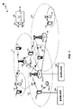
[0036]図1は、本開示の様々な態様による、ワイヤレス通信システム100の一例を概念的に示すブロック図である。ワイヤレス通信システム100は、eノードB(またはセル)105と、ユーザ機器(UE)115と、コアネットワーク130とを含む。eノードB105は、様々な実施形態ではコアネットワーク130またはeノードB105の一部であり得る基地局コントローラ(図示せず)の制御下でUE115と通信し得る。1つまたは複数のUE115は、多重接続性において、UE115をサービスする様々なeノードB105の間のタイミング差を決定および/または報告するための通信構成要素640を含むことができる。1つまたは複数のeノードB105は、UE115のための1つまたは複数の動作のスケジューリングを決定するために、他のeノードBとのUE115から報告されたタイミング差を受信するための通信構成要素1040を含むことができる。eノードB105は、第1のバックホールリンク(backhaul links)132を通してコアネットワーク130と制御情報および/またはユーザデータを通信し得る。実施形態では、eノードB105は、ワイヤードまたはワイヤレス通信リンクであり得る第2のバックホールリンク134を介して互いと直接または間接的に通信し得る。ワイヤレス通信システム100は、複数のキャリア(異なる周波数の波形信号)上での動作をサポートし得る。マルチキャリア送信機は、複数のキャリア上で同時に被変調信号を送信することができる。たとえば、各通信リンク125は、上記で説明した様々な無線技術に従って変調されたマルチキャリア信号であり得る。各被変調信号は、異なるキャリア上で送られ得、制御情報(たとえば、基準信号、制御チャネルなど)、オーバーヘッド情報、データなどを搬送し得る。ワイヤレス通信システム100はまた、複数のフロー上での動作を同時にサポートし得る。いくつかの態様では、複数のフローは、複数のワイヤレスワイドエリアネットワーク(WWAN)またはセルラーフローに対応し得る。他の態様では、複数のフローは、WWANまたはセルラーフローとワイヤレスローカルエリアネットワーク(WLAN)またはWi−Fiフローとの組合せに対応し得る。
[0036] FIG. 1 is a block diagram conceptually illustrating an example of a
[0037]eノードB105は、1つまたは複数の基地局アンテナを介して、UE115とワイヤレス通信し得る。eノードB105のサイトの各々は、それぞれの地理的カバレージエリア110に通信カバレージを与え得る。いくつかの実施形態では、eノードB105は、基地トランシーバ局、無線基地局、アクセスポイント、無線トランシーバ、基本サービスセット(BSS)、拡張サービスセット(ESS)、ノードB、eノードB、ホームノードB、ホームeノードB、または何らかの他の好適な用語で呼ばれることがある。eノードB105のための地理的カバレージエリア110は、カバレージエリアの一部分のみを構成するセクタ(図示せず)に分割され得る。ワイヤレス通信システム100は、異なるタイプのeノードB105(たとえば、マクロ基地局、マイクロ基地局、および/またはピコ基地局)を含み得る。異なる技術のための重複するカバレージエリアがあり得る。
[0037] The
[0038]実装形態では、ワイヤレス通信システム100はLTE/LTE−Aネットワーク通信システムである。LTE/LTE−Aネットワーク通信システムでは、発展型ノードB(eノードB)という用語は、概して、eノードB105を記述するために使用され得る。ワイヤレス通信システム100は、異なるタイプのeノードBが様々な地理的領域にカバレージを与える、異種LTE/LTE−Aネットワークであり得る。たとえば、各eノードB105は、マクロセル、ピコセル、フェムトセル、および/または他のタイプのセルに通信カバレージを与え得る。マクロセルは、比較的大きい地理的エリア(たとえば、半径数キロメートル)をカバーし得、ネットワークプロバイダのサービスに加入しているUE115による無制限アクセスを可能にし得る。ピコセルは、比較的小さい地理的エリア(たとえば、建築物)をカバーし得、ネットワークプロバイダのサービスに加入しているUE115による無制限アクセスを可能にし得る。フェムトセルは、比較的小さい地理的エリア(たとえば、自宅)をカバーし得、無制限アクセスに加えて、フェムトセルとの関連を有するUE115(たとえば、限定加入者グループ(CSG:closed subscriber group)中のUE115、自宅内のユーザのためのUE115など)による制限付きアクセスをも可能にし得る。マクロセルのためのeノードB105はマクロeノードBと呼ばれることがある。ピコセルのためのeノードB105はピコeノードBと呼ばれることがある。また、フェムトセルのためのeノードB105はフェムトeノードBまたはホームeノードBと呼ばれることがある。eノードB105は、1つまたは複数の(たとえば、2つ、3つ、4つなどの)セルをサポートし得る。ワイヤレス通信システム100は、UE115のうちの1つまたは複数によるLTEおよびWLANまたはWiFi(登録商標)の使用をサポートし得る。
[0038] In an implementation, the
[0039]コアネットワーク130は、第1のバックホールリンク132(たとえば、S1インターフェースなど)を介してeノードB105または他のeノードB105と通信し得る。eノードB105はまた、たとえば、第2のバックホールリンク134(たとえば、X2インターフェースなど)を介しておよび/または第1のバックホールリンク132を介して(たとえば、コアネットワーク130を通して)直接または間接的に、互いと通信し得る。ワイヤレス通信システム100は同期動作または非同期動作をサポートし得る。同期動作の場合、eノードB105は同様のフレームタイミングを有し得、異なるeノードB105からの送信は近似的に時間的に整合され得る。非同期動作の場合、eノードB105は異なるフレームタイミングを有し得、異なるeノードB105からの送信は時間的に整合されないことがある。本明細書で説明する技法は、同期動作または非同期動作のいずれかのために使用され得る。
[0039] The
[0040]UE115は、ワイヤレス通信システム100全体にわたって分散され得、各UE115は固定または移動であり得る。UE115は、当業者によって、移動局、加入者局、モバイルユニット、加入者ユニット、ワイヤレスユニット、リモートユニット、モバイルデバイス、ワイヤレスデバイス、ワイヤレス通信デバイス、リモートデバイス、モバイル加入者局、アクセス端末、モバイル端末、ワイヤレス端末、リモート端末、ハンドセット、ユーザエージェント、モバイルクライアント、クライアント、または何らかの他の好適な用語で呼ばれることもある。UE115は、セルラーフォン、携帯情報端末(PDA)、ワイヤレスモデム、ワイヤレス通信デバイス、ハンドヘルドデバイス、タブレットコンピュータ、ラップトップコンピュータ、コードレスフォン、ワイヤレスローカルループ(WLL)局などであり得る。UE115は、マクロeノードB、ピコeノードB、フェムトeノードB、リレーなどと通信することが可能であり得る。
[0040] The
[0041]ワイヤレス通信システム100に示された通信リンク125は、UE115からeノードB105へのアップリンク(UL)送信および/またはeノードB105からUE115へのダウンリンク(DL)送信を含み得る。ダウンリンク送信は順方向リンク送信と呼ばれることもあり、アップリンク送信は逆方向リンク送信と呼ばれることもある。
[0041]
[0042]ワイヤレス通信システム100のいくつかの態様では、UE115は、1つまたは複数のeノードB105によって与えられる2つまたはそれ以上のセルを用いたキャリアアグリゲーション(CA:carrier aggregation)または多重接続性ワイヤレス通信をサポートするように構成され得る。CA/多重接続性ワイヤレス通信のために使用されるeノードB105はコロケートされ得るか、または高速接続を通して接続されるか、および/またはコロケートされないことがある。いずれの場合も、UE115とeノードB105との間のワイヤレス通信のためのコンポーネントキャリア(CC)のアグリゲーションを協調させることは、キャリアアグリゲーションを実行するために使用されている様々なセル間で情報が容易に共有され得るので、より容易に行われ得る。キャリアアグリゲーションのために使用されるeノードB105がコロケートされない(たとえば、遠くに離れているかまたはそれらの間の高速接続を有しない)とき、コンポーネントキャリアのアグリゲーションを協調させることは、追加の態様を伴い得る。たとえば、デュアル接続性(たとえば、2つのコロケートされないeノードB105に接続されたUE115)のためのキャリアアグリゲーションでは、UE115は、第1のeノードB105(たとえば、SeノードBまたはSeNB)の1次セルを通して第1のeノードB105と通信するための構成情報を受信し得る。第1のeノードB105は、2次セルグループまたはSCGと呼ばれるセルのグループを含み得、それは、第1のeノードB105の、1つまたは複数の2次セルと1次セルまたはPCellSCGとを含む。UE115はまた、第2のeノードB105(たとえば、MeノードBまたはMeNB)の第2の1次セルを通して第2のeノードB105と通信するための構成情報を受信し得る。第2のeノードB105は、マスタセルグループまたはMCGと呼ばれるセルのグループを含み得、それは、第2のeノードB105の、1つまたは複数の2次セルと1次セルまたはPCellMCGとを含む。
[0042] In some aspects of the
[0043]ワイヤレス通信システム100のいくつかの態様では、デュアル接続性のためのキャリアアグリゲーションは、2次eノードB105(たとえば、SeノードBまたはSeNB)がそれのセルのうちの1つをPCellSCGとして動作させるように構成されることを伴い得る。2次eノードB105は、UE115がマスタeノードB105(たとえば、MeノードBまたはMeNB)と通信している間にUE115が2次eノードB105と通信するためにPCellSCGを通して構成情報をUE115に送信し得る。マスタeノードB105は、同じUE115が他方のeノードB105と通信するために、それのPCellを介してそのUE115に構成情報を送信し得る。2つのeノードB105はコロケートされないことがある。
[0043] In some aspects of the
[0044]本明細書で説明する例では、UE115は、本明細書でさらに説明するように、MCGとSCGとの間のタイミング差を決定し、および/または、MCG、SCG、または他のネットワークエンティティの1つまたは複数のeノードB(たとえば、eノードB105)にタイミング差を報告するために構成され得る。たとえば、UE115は、eノードB105あるいは関係するセルまたはセルグループのタイミングがそれから決定され得る、MCGおよび/またはSCGのeノードB105からのシステム情報(たとえば、1つまたは複数のマスタ情報ブロック(MIB))を収集することができる。したがって、UE115は、システム情報に基づいて、MCGの1つまたは複数のeノードB105およびSCGの1つまたは複数のeノードB105に同期することができ、eノードB105と同期するために使用されたタイミングに基づいて、MCGとSCGとの間のタイミング差を決定することができる。したがって、UE115は、(たとえば、MCGおよび/またはSCGあるいは関係するeノードB105を介して)ネットワークに決定されたタイミング差を報告することができ、タイミング差は、いくつかの動作(たとえば、測定ギャップ、通信を受信するためのリソースがその間オンにされるべきであるDRXオン持続時間など)のためのリソースを整合させるために使用され得る。そのような整合がなければ、SCGは、eノードB105とは矛盾して、それらの動作のためにUE115を別個にスケジュールし得、これは、それらの動作のためのリソースの不要な利用を生じ得る。
[0044] In the examples described herein, the
[0045]たとえば、MCGのeノードB105とSCGのeノードB105とは、タイミングにおいて整合されないことがあり、それにより、MCGとSCGとは、同様の時間に位置する異なるサブフレーム(たとえば、異なるシステムフレーム番号(SFN)など)を有し、および/またはサブフレーム境界の異なる整合を有することがある。したがって、測定ギャップ、DRXオン持続時間などのタイミング整合を仮定するいくつかの構成は、タイミング差が、そのような動作のためにUE115をスケジュールするセルグループのうちの少なくとも1つにおけるeノードB105のうちの少なくとも1つに与えられない限り、必要に応じて機能しないことがある。したがって、たとえば、UE115は、タイミング差を決定し、報告することができ、eノードB105のうちの少なくとも1つが、構成のために割り当てられるリソースを他のeノードB105と整合させる際に、報告されたタイミング差を使用することができ、これは、構成のためのサブフレームを整合させること、システムフレームが他のeノードB105と同時に開始するように、同じSFNを使用するかまたはサブフレームを整合させるように、eノードBのタイミングを整合させることなどを含むことができる。サブフレーム境界が整合されない場合、および/またはUE115によって測定され、報告されるタイミング差がある程度の不正確さを含み得る場合、本明細書でさらに説明するように、タイミングを整合させるeノードB105は、サブフレーム境界の不整合および/または受信された報告の潜在的不正確さに基づいて、いくつかの構成のためのタイミングを整合させる際にスケジュールすべき追加のサブフレームの数を決定することができることを諒解されたい。
[0045] For example, the
[0046]その上、UE115は、周期時間トリガ、仮定されたタイミングを越えるかまたは前に報告されたタイミング差を越えるタイミングにおける測定された差がしきい値を超えること、いくつかのサブフレームがタイミング変化によって影響を及ぼされることの決定、タイミング差を測定および報告することを禁止する禁止タイマーの満了など、1つまたは複数のトリガに基づいて、eノードB間のタイミング差を測定および/または報告することを決定することができる。さらに、一例では、UE115が第1のeノードB105との通信を開始した場合、UE115は、第1のeノードBと第2のeノードBとの間のタイミング差が報告されるまで、第2のeノードB105との通信が確立され得るという報告などを受信することの確認が受信されるまでなど、第2のeノードB105との通信を確立することを遅延させることができる。
[0046] Moreover, the
[0047]図2は、本開示の一態様に従って構成されたeノードB210およびUE250の例を概念的に示すブロック図である。たとえば、図2に示されているように、システム200のeノードB210およびUE250は、それぞれ、図1中のeノードBのうちの1つおよびUEのうちの1つであり得る。したがって、たとえば、UE250は、多重接続性において、UE250をサービスする様々なeノードB210の間のタイミング差を決定および/または報告するための通信構成要素640を含むことができる。eノードB210は、UE250のための1つまたは複数の動作のスケジューリングを決定するために、他のeノードBとのUE250から報告されたタイミング差を受信するための通信構成要素1040を含むことができる。いくつかの態様では、eノードB210は、多重接続性(たとえば、デュアル接続性)、キャリアアグリゲーションなどをサポートし得る。eノードB210は、それのMCG中のセルのうちの1つをPCellMCGとして構成させられたMeノードBであるか、またはそれのSCG中のそれのセルのうちの1つをPCellSCGとして構成させられたSeノードBであり得る。いくつかの態様では、UE250も、多重接続性キャリアアグリゲーションをサポートし得る。UE250は、PCellMCGおよび/またはPCellSCGを介してeノードB210から構成情報を受信し得る。eノードB210はアンテナ2341~tを装備し得、UE250はアンテナ2521~rを装備し得、ここにおいて、tおよびrは1以上の整数である。
[0047] FIG. 2 is a block diagram conceptually illustrating an example of an
[0048]eノードB210において、eノードB送信プロセッサ220は、eノードBデータソース212からデータを受信し、eノードBコントローラ/プロセッサ240から制御情報を受信し得る。制御情報は、PBCH、PCFICH、物理的ハイブリッド自動再送/要求(HARQ)インジケータチャネル(PHICH)、PDCCHなどの上で搬送され得る。データは、PDSCHなどの上で搬送され得る。eノードB送信プロセッサ220は、データシンボルおよび制御シンボルを取得するために、それぞれデータおよび制御情報を処理(たとえば、符号化およびシンボルマッピング)し得る。eノードB送信プロセッサ220はまた、たとえば、PSS、SSS、およびセル固有基準信号(RS)のための基準シンボルを生成し得る。eノードB送信(TX)多入力多出力(MIMO)プロセッサ230は、適用可能な場合、データシンボル、制御シンボル、および/または基準シンボルに対して空間処理(たとえば、プリコーディング)を実行し得、出力シンボルストリームをeノードB変調器/復調器(MOD/DEMOD)2321~tに与え得る。各eノードB変調器/復調器232は、出力サンプルストリームを取得するために、(たとえば、OFDMなどのために)それぞれの出力シンボルストリームを処理し得る。各eノードB変調器/復調器232はさらに、ダウンリンク信号を取得するために、出力サンプルストリームを処理(たとえば、アナログへの変換、増幅、フィルタ処理、およびアップコンバート)し得る。変調器/復調器2321~tからのダウンリンク信号は、それぞれアンテナ2341~tを介して送信され得る。
[0048] At
[0049]UE250において、UEアンテナ2521~rは、eノードB210からダウンリンク信号を受信し得、受信信号をそれぞれUE変調器/復調器(MOD/DEMOD)2541~rに与え得る。各UE変調器/復調器254は、入力サンプルを取得するために、それぞれの受信信号を調整(たとえば、フィルタ処理、増幅、ダウンコンバート、およびデジタル化)し得る。各UE変調器/復調器254はさらに、受信シンボルを取得するために、(たとえば、OFDMなどのために)入力サンプルを処理し得る。UE MIMO検出器256は、すべてのUE変調器/復調器2541~rから受信シンボルを取得し、適用可能な場合は受信シンボルに対してMIMO検出を実行し、検出シンボルを与え得る。UE受信プロセッサ258は、検出シンボルを処理(たとえば、復調、デインターリーブ、および復号)し、UE250の復号されたデータをUEデータシンク260に与え、復号された制御情報をUEコントローラ/プロセッサ280に与え得る。
[0049] At
[0050]アップリンク上では、UE250において、UE送信プロセッサ264は、UEデータソース262から(たとえば、PUSCHのための)データを受信し、処理し得、UEコントローラ/プロセッサ280から(たとえば、PUCCHのための)制御情報を受信し、処理し得る。UE送信プロセッサ264はまた、基準信号のための基準シンボルを生成し得る。UE送信プロセッサ264からのシンボルは、適用可能な場合はUE TX MIMOプロセッサ266によってプリコーディングされ、さらに(たとえば、SC−FDMなどのために)UE変調器/復調器2541~rによって処理され、eノードB210に送信され得る。eノードB210において、UE250からのアップリンク信号は、eノードBアンテナ234によって受信され、eノードB変調器/復調器232によって処理され、適用可能な場合はeノードB MIMO検出器236によって検出され、UE250によって送られた復号されたデータと制御情報とを取得するために、eノードB受信プロセッサ238によってさらに処理され得る。eノードB受信プロセッサ238は、復号されたデータをeノードBデータシンク246に与え、復号された制御情報をeノードBコントローラ/プロセッサ240に与え得る。
[0050] On the uplink, at
[0051]eノードBコントローラ/プロセッサ240およびUEコントローラ/プロセッサ280は、それぞれeノードB210における動作およびUE250における動作を指示し得る。UE250におけるUEコントローラ/プロセッサ280ならびに/または他のプロセッサおよびモジュールはまた、たとえば、図6および/または図10に示されている機能ブロック、ならびに/あるいは本明細書で説明する技法のための他のプロセス(たとえば、図8、図9、図11、図12などに示されているフローチャート)を実行するか、またはその実行を指示し得る。いくつかの態様では、これらの機能ブロックおよび/またはプロセスの実行の少なくとも一部分は、UEコントローラ/プロセッサ280中のブロック281によって実行され得る。eノードBメモリ242およびUEメモリ282は、それぞれeノードB210およびUE250のためのデータおよびプログラムコードを記憶し得る。たとえば、UEメモリ282は、eノードB210および/または別のeノードBによって与えられる多重接続性のための構成情報を記憶し得る。スケジューラ244は、ダウンリンクおよび/またはアップリンク上でのデータ送信のためにUE250をスケジュールするために使用され得る。
[0051] The eNode B controller /
[0052]一構成では、UE250は、少なくとも第1のセルによってサービスされる第1の接続を確立するための手段を含み得る。UE250はまた、少なくとも第1のセルおよび少なくとも第2のセルと通信することを可能にするために、少なくとも第2のセルによってサービスされる第2の接続を確立するための手段を含み得る。UE250は、少なくとも第1のセルと少なくとも第2のセルとの間のタイミング差を決定するための手段をさらに含み得る。UE250はまた、報告構成に少なくとも部分的に基づいて、第1の接続を介して少なくとも第1のセルに、または第2の接続を介して少なくとも第2のセルにタイミング差を報告するための手段を含むことができる。別の構成では、UE250は、追加または代替として、少なくとも第2のセルによってサービスされる第2の接続を確立するための構成メッセージを受信するための手段と、少なくとも第1のセルと少なくとも第2のセルとの間のタイミング差を推定するための手段と、第1の接続を介して少なくとも第1のセルにタイミング差を報告するための手段と、少なくとも第1のセルにタイミング差を報告することに少なくとも部分的に基づいて少なくとも第2のセルによってサービスされる第2の接続を構成するための手段とを含むことができる。一態様では、上述の手段は、上述の手段によって具陳された機能を実行するように構成された、UEコントローラ/プロセッサ280、UEメモリ282、UE受信プロセッサ258、UE MIMO検出器256、UE変調器/復調器254、およびUEアンテナ252であり得る。別の態様では、上述の手段は、上述の手段によって具陳された機能を実行するように構成されたモジュール、構成要素、または任意の装置であり得る。そのようなモジュール、構成要素、または装置の例は、図6および/または図10に関して説明され得る。
[0052] In one configuration, the
[0053]図3は、本開示の一態様による、UEにおけるキャリアおよび/または接続のアグリゲーションを概念的に示すブロック図である。アグリゲーションは、1つまたは複数のコンポーネントキャリア1〜N(CC1〜CCN)を使用してeノードB305−aと通信し、および/または1つまたは複数のコンポーネントキャリアM〜P(CCM〜CCP)を使用して2次eノードB305−bと通信することができる、マルチモードUE315を含むシステム300中で行われ得る。たとえば、eノードB305−aおよび/または2次eノードB305−bは、AP、フェムトセル、ピコセルなどを含み得る。UE315は、多重接続性において、UE315をサービスする様々なeノードB305−a、305−bの間のタイミング差を決定および/または報告するための通信構成要素640を含むことができる。eノードB305−aおよび/または305−bは、UE315のための1つまたは複数の動作のスケジューリングを決定するために、他のeノードBとのUE315から報告されたタイミング差を受信するための通信構成要素1040を含むことができる。UE315は、この例では、2つ以上の無線アクセス技術(RAT)をサポートするマルチモードUEであり得る。たとえば、UE315は、少なくともWWAN無線アクセス技術(たとえば、LTE)および/またはWLAN無線アクセス技術(たとえば、Wi−Fi)をサポートし得る。マルチモードUEはまた、本明細書で説明するように、キャリアアグリゲーションおよび/または多重接続性キャリアアグリゲーションをサポートし得る。UE315は、図1、図2、図4、図5、図6、図10のUEのうちの1つの一例であり得る。eノードB305−aおよび/または2次eノードB305−bは、図1、図2、図4、図5、図6、図10のeノードB、基地局、ネットワークエンティティなどのうちの1つの一例であり得る。1つのUE315、1つのeノードB305−a、および1つの2次eノードB305−bのみが図3に示されているが、システム300が、任意の数のUE315、eノードB305−a、および/または2次eノードB305−bを含むことができることが諒解されよう。特定の一例では、UE315は、1つまたは複数のLTEコンポーネントキャリア330−1〜330−Nを介して1つのeノードB305−aと通信する間に別の1つまたは複数のLTEコンポーネントキャリア330−M〜330−Pを介して別のeノードB305−bと通信することができる。
[0053] FIG. 3 is a block diagram conceptually illustrating carrier and / or connection aggregation at a UE according to one aspect of the present disclosure. The aggregation communicates with the eNodeB 305-a using one or more component carriers 1-N (CC 1 -CC N ) and / or one or more component carriers M- P (CC M- CC P ) may be used in a
[0054]eノードB305−aは、LTEコンポーネントキャリアCC1〜CCN330上の順方向(ダウンリンク)チャネル332−1〜332−Nを介してUE315に情報を送信することができる。さらに、UE315は、LTEコンポーネントキャリアCC1〜CCN上の逆方向(アップリンク)チャネル334−1〜334−Nを介してeノードB305−aに情報を送信することができる。同様に、eノードB305−bは、LTEコンポーネントキャリアCCM〜CCP330上の順方向(ダウンリンク)チャネル332−m〜332−pを介してUE315に情報を送信し得る。さらに、UE315は、LTEコンポーネントキャリアCCM〜CCP330上の逆方向(アップリンク)チャネル334−m〜334−pを介してeノードB305−bに情報を送信し得る。
[0054] The eNode B 305-a may send information to the
[0055]図3ならびに開示する実施形態のうちのいくつかに関連する他の図の様々なエンティティについて説明する際、説明の目的で、3GPP LTEまたはLTE−Aワイヤレスネットワークに関連する名称が使用される。ただし、システム300は、限定はしないが、OFDMAワイヤレスネットワーク、CDMAネットワーク、3GPP2 CDMA2000ネットワークなどの他のネットワークにおいて動作することができることを諒解されたい。
[0055] In describing various entities in FIG. 3 as well as other diagrams related to some of the disclosed embodiments, for purposes of explanation, names associated with 3GPP LTE or LTE-A wireless networks are used. The However, it should be appreciated that the
[0056]マルチキャリア動作中、異なるUE315に関連するダウンリンク制御情報(DCI)メッセージは、複数のコンポーネントキャリア上で搬送され得る。たとえば、PDCCH上のDCIは、物理ダウンリンク共有チャネル(PDSCH:physical downlink shared channel)送信のためにUE315によって使用されるように構成された同じコンポーネントキャリア上に含まれ得る(すなわち、同一キャリアシグナリング)。代替または追加として、DCIは、PDSCH送信のために使用されるターゲットコンポーネントキャリアとは異なるコンポーネントキャリア上で搬送され得る(すなわち、クロスキャリアシグナリング)。いくつかの実装形態では、半静的に有効化され得るキャリアインジケータフィールド(CIF)は、PDSCH送信のためにターゲットキャリア以外のキャリアからのPDCCH制御シグナリングの送信を可能にするために、一部または全部のDCIフォーマット中に含まれ得る(クロスキャリアシグナリング)。
[0056] During multi-carrier operation, downlink control information (DCI) messages associated with
[0057]本例では、UE315は、1つのeノードB305−aからデータを受信し得る。しかしながら、セルエッジ上のユーザは、データレートを制限することがある高いセル間干渉を経験することがある。マルチフローは、UEが同時に2つのeノードB305−aおよび305−bからデータを受信することを可能にする。いくつかの態様では、2つのeノードB305−aは、コロケートされないことがあり、多重接続性キャリアアグリゲーションをサポートするように構成され得る。マルチフローは、UEが同時に2つの隣接するセル中の2つのセルタワーの範囲内にあるとき(以下の図5参照)、2つのまったく別個のストリーム中で2つのeノードB305−a/305−bからのデータを送信および受信することによって動作する。UEは、デバイスがいずれかのeノードBの到達範囲のエッジ上にあるとき、同時に2つのeノードB305−a/305−bと通話する。同時に2つの異なるeノードBからモバイルデバイスに2つの独立データストリームをスケジュールすることによって、マルチフローは、ワイヤレス通信ネットワークにおける不均一なローディングを活用する。これは、セルエッジユーザ経験を向上させるのを助けるとともに、ネットワーク容量を増大させる。一例では、セルエッジにおけるユーザのためのスループットデータ速度が倍になり得る。いくつかの態様では、マルチフローはまた、UEがWWANタワー(たとえば、セルラータワー)とWLANタワー(たとえば、AP)の両方の到達範囲内にあるとき、それらのタワーと同時に通話するUEの能力を指すことがある。そのような場合、タワーは、タワーがコロケートされないとき、多重接続を通してキャリアアグリゲーションをサポートするように構成され得る。図4は、本開示の一態様による、UE415とPDN440(たとえば、インターネットまたはインターネットにアクセスするための1つもしくは複数の構成要素)との間のデータ経路445および450の一例を概念的に示すブロック図である。データ経路445、450は、同じRATを使用することも使用しないこともある、異なるeノードB405−aおよび405−bからのデータをアグリゲートするためのワイヤレス通信システム400のコンテキスト内で示されている。図2のシステム200は、ワイヤレス通信システム400の部分の一例であり得る。ワイヤレス通信システム400は、マルチモードUE415、eノードB405、(たとえば、X2インターフェースに基づく)バックホールリンク438を介してeノードB405−aに結合され得る2次eノードB405−b、発展型パケットコア(EPC)480、PDN440、およびピアエンティティ455を含み得る。UE415は、多重接続性において、UE415をサービスする様々なeノードB405−a、405−bの間のタイミング差を決定および/または報告するための通信構成要素640を含むことができる。eノードB405−aおよび/または405−bは、UE415のための1つまたは複数の動作のスケジューリングを決定するために、他のeノードBとのUE415から報告されたタイミング差を受信するための通信構成要素1040を含むことができる。マルチモードUE415は、キャリアアグリゲーション、多重接続性(たとえば、デュアル接続性)キャリアアグリゲーションなどをサポートするように構成され得る。EPC480は、モビリティ管理エンティティ(MME)430と、サービングゲートウェイ(SGW)432と、PDNゲートウェイ(PGW)434とを含み得る。ホーム加入者システム(HSS)435は、MME430に通信可能に結合され得る。UE415は、LTE無線機420とLTE無線機425とを含み得る。これらの要素は、前または後の図を参照しながら上記で説明したそれらのカウンターパートのうちの1つまたは複数の態様を表し得る。たとえば、UE415は、図1、図2、図3、図5、図6、図10におけるUEの一例であり得、eノードB405−aは、図1、図2、図3、図5、図6、図10のeノードB/基地局/ネットワークエンティティの一例であり得、2次eノードB405−bは、図1、図2、図3、図5、図6、図10の2次eノードB/基地局/ネットワークエンティティの一例であり得、および/またはEPC480は、図1のコアネットワーク130の一例であり得る。図4におけるeノードB405−aおよび405−bは、互いにコロケートされないことがあるか、またはさもなければ高速通信していないことがある。さらに、一例では、eノードB405および405−bは、異なるEPC480と通信し得る。
[0057] In this example, the
[0058]再び図4を参照すると、eノードB405−aおよび/または405−bは、(たとえば、1つまたは複数のeノードBを用いた)1つまたは複数のLTEコンポーネントキャリアのアグリゲーションを使用して、UE415にPDN440へのアクセスを与えることが可能であり得る。したがって、UE415は、デュアル接続性でのキャリアアグリゲーションを伴い得、ここで、一方の接続は1つのネットワークエンティティ(eノードB405−a)に対してであり、他方の接続は異なるネットワークエンティティ(eノードB405−b)に対してである。UE415は、複数のeノードBを用いた多重接続性ワイヤレス通信、eノードBの複数のセルを用いたキャリアアグリゲーションなどを与えるために、EPC408を横断してPDN440にアクセスするかまたは横断せずにPDN440にアクセスする追加のデータ経路445、450を介して、追加のeノードB405−aおよび/または405−bと通信することができることを諒解されたい。PDN440へのこのアクセスを使用して、UE415はピアエンティティ455と通信し得る。eノードB405−aおよび/または405−bは、EPC480を通して(たとえば、データ経路445および/または450を通して)、PDN440へのアクセスを与え得る。図示された例では、UE415は、eノードB固有のベアラを介して、MeノードBとしてのeノードB405およびSeノードBとしてのeノードB405−bと通信することができる。一例では、eノードB405−aおよび405−bは、EPC480に与えるためのUE415通信をアグリゲートするために、X2接続438を介して互いに通信することができる。この例では、UE415は、PDN440にアクセスするためのデータ経路445および450を介した通信をマッピングすることができる、eノードB405および/または2次eノードB405−b(あるいは関係するセルまたはセルグループ)を用いたベアラを使用することによって、PDN440にアクセスすることができる。
[0058] Referring again to FIG. 4, eNodeBs 405-a and / or 405-b use aggregation of one or more LTE component carriers (eg, with one or more eNodeBs). Thus, it may be possible to give
[0059]MME430は、UE415とEPC480との間のシグナリングを処理する制御ノードであり得る。MME430はベアラおよび接続管理を行い得る。MME430は、したがって、UE415のためにアイドルモードUEトラッキングおよびページングと、ベアラアクティブ化および非アクティブ化と、SGW選択とを担当し得る。MME430は、S1−MMEインターフェースを介してeノードB405−aおよび/または405−bと通信し得る。MME430は、UE415をさらに認証し、UE415との非アクセス層(NAS:Non-Access Stratum)シグナリングを実装し得る。
[0059] The
[0060]HSS435は、機能の中でも、加入者データを記憶し、ローミング制限を管理し、加入者のためのアクセス可能アクセスポイント名(APN:access point name)を管理し、加入者をMME430に関連付け得る。HSS435は、3GPP団体によって規格化された発展型パケットシステム(EPS)アーキテクチャによって定義されたS6aインターフェースを介してMME430と通信し得る。
[0060] The
[0061]LTEを介して送信されるすべてのユーザIPパケットは、eノードB405−aおよび/または405−bを通してSGW432に転送され得、SGW432は、S5シグナリングインターフェースを介してPDNゲートウェイ434に接続され、S11シグナリングインターフェースを介してMME430に接続され得る。SGW432は、ユーザプレーン中に存在し、eノードB間ハンドオーバと、異なるアクセス技術間のハンドオーバとのためのモビリティアンカーとして働き得る。PDNゲートウェイ434はUEのIPアドレス割振りならびに他の機能を与え得る。
[0061] All user IP packets sent over LTE may be forwarded to
[0062]PDNゲートウェイ434は、SGiシグナリングインターフェースを介して、PDN440など、1つまたは複数の外部パケットデータネットワークへの接続性を与え得る。PDN440は、インターネット、イントラネット、IPマルチメディアサブシステム(IMS:IP Multimedia Subsystem)、パケット交換(PS:Packet-Switched)ストリーミングサービス(PSS:PS Streaming Service)、および/または他のタイプのPDNを含み得る。
[0062] The
[0063]本例では、UE415とEPC480との間のユーザプレーンデータは、トラフィックがLTEリンクのデータ経路445を介して流れるのか、データ経路450を介して流れるのかにかかわらず、1つまたは複数のEPSベアラの同じセットを横断し得る。1つまたは複数のEPSベアラのセットに関係するシグナリングまたは制御プレーンデータは、eノードB405−aおよび/または405−bを経由して、UE415のLTE無線機420とEPC480のMME430との間で送信され得る。
[0063] In this example, user plane data between the
[0064]図4の態様についてLTEに関して説明したが、アグリゲーションおよび/または多重接続に関する同様の態様はまた、UMTSあるいは他の同様のシステムまたはネットワークワイヤレス通信無線技術に関して実装され得る。 [0064] Although the aspects of FIG. 4 have been described with respect to LTE, similar aspects regarding aggregation and / or multiple connections may also be implemented with respect to UMTS or other similar systems or network wireless communication radio technologies.
[0065]図5は、本開示の一態様による、多重接続性キャリアアグリゲーションを概念的に示す図である。ワイヤレス通信システム500が、UE515をサービスするように構成され得る、マスタセルグループまたはMCG(またはPCG)と呼ばれるセルのセットまたはグループを有するマスタeノードB505−a(MeノードBまたはMeNB)を含み得る。MCGは、1つの1次セル(PCellMCG)510−aと、1つまたは複数の2次セル510−b(1つのみが示されている)とを含み得る。ワイヤレス通信システム500はまた、UE515をサービスするように構成され得る、2次セルグループまたはSCGと呼ばれるセルのセットまたはグループを有する2次eノードB505−b(SeノードBまたはSeNB)を含み得る。SCGは、1つの1次セル(PCellSCG)512−aと、1つまたは複数の2次セル512−b(1つのみが示されている)とを含み得る。また、多重接続性(たとえば、デュアル接続性)のためにキャリアアグリゲーションをサポートするUE515が示されている。UE515は、通信リンク525−aを介してMeノードB505−a、または関係するPCellMCGと通信し、通信リンク525−bを介してSeノードB505−b、または関係するPCellSCGと通信し得る。UE515は、多重接続性において、UE515をサービスする様々なeノードB505−a、505−bの間のタイミング差を決定および/または報告するための通信構成要素640を含むことができる。eノードB505−aおよび/または505−bは、UE515のための1つまたは複数の動作のスケジューリングを決定するために、他のeノードBとのUE515から報告されたタイミング差を受信するための通信構成要素1040を含むことができる。
[0065] FIG. 5 is a diagram conceptually illustrating multiple connectivity carrier aggregation according to one aspect of the present disclosure. The
[0066]一例では、UE515は、同じeノードBからのコンポーネントキャリアをアグリゲートし得るか、あるいはコロケートされたまたはコロケートされないeノードBからのコンポーネントキャリアをアグリゲートし得る。そのような例では、使用されている様々なセル(たとえば、異なるコンポーネントキャリア(CC))は、それらが、同じeノードBによって扱われるか、または制御情報を通信することができるeノードBによって扱われるかのいずれかであるので、容易に協調させられ得る。UE515が、図5の例の場合のように、コロケートされない2つのeノードBと通信しているときにキャリアアグリゲーションを実行するとき、キャリアアグリゲーション動作は、様々なネットワーク状態により異なり得る。この場合、2次eノードB505−bにおいて1次セル(PCellSCG)を確立することは、2次eノードB505−bが1次eノードB505−aとコロケートされなくても、UE515において行われるべき適切な構成および制御を可能にし得る。
[0066] In one example, the
[0067]図5の例では、キャリアアグリゲーションは、MeノードB505−aのPCellMCGによるいくつかの機能を伴い得る。たとえば、PCellMCGは、いくつかの例を挙げれば、物理アップリンク制御チャネル(PUCCH)、競合ベースランダムアクセス制御チャネル(RACH)、および半永続的スケジューリングなど、いくつかの機能を扱い得る。コロケートされないeノードBへのデュアル接続性または多重接続性を用いたキャリアアグリゲーションは、キャリアアグリゲーションが他の方法で実行される様式に対していくつかの拡張および/または変更を行わなければならないことを伴い得る。拡張および/または変更のうちのいくつかは、上記で説明したように、UE515がMeノードB505−aとSeノードB505−bとに接続されることを伴い得る。他の特徴は、たとえば、タイマー調整グループ(TAG)にeノードBのうちの1つのセルを備えさせること、SeノードB505−b上で可能にされる競合ベースおよび競合なしランダムアクセス(RA)と、MeノードB505−aのためのおよびSeノードB505−bに対する別個の間欠受信(DRX)プロシージャとを有すること、UE515に、バッファステータス報告(BSR)を1つまたは複数のベアラ(たとえば、eノードB固有ベアラまたはスプリットベアラ)がサービスされるeノードBに送らせること、ならびに2次eノードB505−b中のPCellSCGに関して電力ヘッドルーム報告(PHR)、電力制御、半永続的スケジューリング(SPS)、および論理チャネル優先度付けのうちの1つまたは複数を可能にすることを含み得る。上記で説明した拡張および/または変更、および本開示で与えられる他のものとしてのウェルは、限定ではなく例示のためであることが意図される。
[0067] In the example of FIG. 5, carrier aggregation may involve several functions by the PCell MCG of Me Node B 505-a. For example, the PCell MCG may handle several functions, such as physical uplink control channel (PUCCH), contention based random access control channel (RACH), and semi-persistent scheduling, to name a few examples. Carrier aggregation using dual connectivity or multiple connectivity to uncoordinated eNodeBs may require some extension and / or modification to the manner in which carrier aggregation is performed in other ways. Can accompany. Some of the enhancements and / or changes may involve
[0068]デュアル接続性におけるキャリアアグリゲーションのために、異なる機能はMeノードB505−aとSeノードB505−bとの間で分割され得る。たとえば、異なる機能は、MeノードB505−aとSeノードB505−bとの間で静的に分割されるか、または1つまたは複数のネットワークパラメータに基づいてMeノードB505−aとSeノードB505−bとの間で動的に分割され得る。一例では、MeノードB505−aは、PCellMCGを介して、限定はしないが、初期構成、セキュリティ、システム情報、および/または無線リンク障害(RLF)に関する機能など、(たとえば、メディアアクセス制御(MAC)レイヤの上の)上位レイヤ機能を実行し得る。図5の例において説明するように、PCellMCGは、MCGに属するMeノードB505−aのセルのうちの1つとして構成され得る。PCellMCGは、MCG内の下位レイヤ機能(たとえば、MAC/PHYレイヤ)を与えるように構成され得る。 [0068] Due to carrier aggregation in dual connectivity, different functions may be split between Me Node B 505-a and Se Node B 505-b. For example, different functions may be statically divided between Me Node B 505-a and Se Node B 505-b, or Me Node B 505-a and Se Node B 505-based on one or more network parameters. It can be dynamically divided between b. In one example, the Me Node B 505-a can communicate via PCell MCG , such as, but not limited to, initial configuration, security, system information, and / or functions related to radio link failure (RLF) (eg, media access control (MAC Higher layer functions (above layer) may be performed. As described in the example of FIG. 5, the PCell MCG may be configured as one of the cells of the Me Node B 505-a belonging to the MCG. The PCell MCG may be configured to provide lower layer functions within the MCG (eg, MAC / PHY layer).
[0069]一例では、SeノードB505−bは、SCGのための下位レイヤ機能(たとえば、MAC/PHYレイヤ)の構成情報を与え得る。構成情報は、たとえば、1つまたは複数の無線リソース制御(RRC)メッセージとしてPCellSCGによって与えられ得る。PCellSCGは、SCG中のセルの間で最低セルインデックス(たとえば、識別子またはID)を有するように構成され得る。たとえば、PCellSCGを介してSeノードB505−bによって実行される機能のうちのいくつかは、PUCCHを搬送すること、PCellSCGのDRX構成に従うようにSCG中のセルを構成すること、SeノードB505−b上の競合ベースおよび競合なしランダムアクセスのためのリソースを構成する、PUCCHのための送信電力制御(TPC)コマンドを有するダウンリンク(DL)許可を搬送すること、SCG中の他のセルのためのPCellSCGに基づいて経路損失を推定すること、SCGに共通探索空間を与えること、ならびにUE515にSPS構成情報を与えることを含み得る。
[0069] In one example, Se Node B 505-b may provide configuration information for lower layer functions (eg, MAC / PHY layer) for SCG. The configuration information may be provided by the PCell SCG , for example, as one or more radio resource control (RRC) messages. The PCell SCG may be configured to have the lowest cell index (eg, identifier or ID) among cells in the SCG. For example, some of the functions performed by Se Node B 505-b via PCell SCG are to carry PUCCH, configure cells in the SCG to follow the PCX SCG DRX configuration,
[0070]いくつかの態様では、PCellMCGは、たとえば、セキュリティ、ネットワークへの接続、初期接続、および/または無線リンク障害などの上位レベル機能をUE515に与えるように構成され得る。PCellMCGは、MCG中のセルのための物理アップリンク制御チャネル(PUCCH)を搬送すること、MCGの間で最低セルインデックスを含むこと、MCGセルが同じ間欠受信(DRX)構成を有することを可能にすること、MeノードB505−a上で競合ベースランダムアクセスと競合なしランダムアクセスの一方または両方のためのランダムアクセスリソースを構成すること、ダウンリンク許可がPUCCHのための送信電力制御(TPC)コマンドを搬送することを可能にすること、MCG中のセルのための経路損失推定を可能にすること、MeノードB505−aのための共通探索空間を構成すること、および/あるいは半永続的スケジューリングを構成することを行うように構成され得る。
[0070] In some aspects, the PCell MCG may be configured to provide the
[0071]いくつかの態様では、PCellSCGは、SCG中のセルのためのPUCCHを搬送すること、SCGの間で最低セルインデックスを含むこと、SCGセルが同じDRX構成を有することを可能にすること、SeノードB505−b上で競合ベースランダムアクセスと競合なしランダムアクセスの一方または両方のためのランダムアクセスリソースを構成すること、ダウンリンク許可がPUCCHのためのTPCコマンドを搬送することを可能にすること、SCG中のセルのための経路損失推定を可能にすること、SeノードB505−bのための共通探索空間を構成すること、および/あるいは半永続的スケジューリングを構成することを行うように構成され得る。 [0071] In some aspects, the PCell SCG may carry the PUCCH for cells in the SCG, include the lowest cell index among the SCGs, and allow the SCG cells to have the same DRX configuration. Configuring random access resources for contention based random access and / or contention free random access on Se Node B 505-b, allowing downlink grants to carry TPC commands for PUCCH To enable path loss estimation for cells in the SCG, configure a common search space for Se Node B 505-b, and / or configure semi-persistent scheduling Can be configured.
[0072]図5の例に戻ると、UE515は、MeノードB505−aおよびSeノードB505−bのための並列PUCCHおよび物理アップリンク共有チャネル(PUSCH)構成をサポートし得る。場合によっては、UE515は、両方のキャリアグループに適用可能であり得る(たとえば、UE515ベースの)構成を使用し得る。これらのPUCCH/PUSCH構成は、たとえば、RRCメッセージを通して与えられ得る。
[0072] Returning to the example of FIG. 5,
[0073]UE515はまた、MeノードB505−aおよびSeノードB505−bについて、肯定応答(ACK)/否定応答(NACK)およびチャネル品質インジケータ(CQI)の同時送信のための、およびACK/NACK/サウンディング基準信号(SRS)のための並列構成をサポートし得る。場合によっては、UE515は、両方のキャリアグループに適用可能であり得る(たとえば、UEベースのおよび/あるいはMCGまたはSCGベースの)構成を使用し得る。これらの構成は、たとえば、RRCメッセージを通して与えられ得る。
[0073]
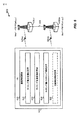
[0074]図6は、本開示の一態様に従って構成されたUE615および構成要素の一例を概念的に示すブロック図600である。本明細書において図6と併せて説明する図8〜図9に、本開示の態様による例示的な方法800および900を示す。図8および図9において以下で説明する動作は、特定の順序でおよび/または例示的な構成要素によって実行されるものとして提示されるが、アクションの順序およびアクションを実行する構成要素は、実装形態に応じて変更され得ることを理解されたい。その上、以下のアクションまたは機能は、特別にプログラムされたプロセッサ、特別にプログラムされたソフトウェアまたはコンピュータ可読媒体を実行するプロセッサによって、あるいは説明するアクションまたは機能を実行することが可能なハードウェア構成要素および/またはソフトウェア構成要素の任意の他の組合せによって実施され得ることを理解されたい。
[0074] FIG. 6 is a block diagram 600 conceptually illustrating an example of a
[0075]図6を参照すると、図600のeノードB605−a(PCellMCGのMeノードB)、eノードB605−b(PCellSCGのSeノードB)、およびUE615は、様々な図に記載されている基地局/eノードB(またはAP)およびUEのうちの1つであり得る。MeノードB605−a、またはそれに関係するPCellMCG、およびUE615は、通信リンク625−aを介して通信し得る。SeノードB605−b、またはそれに関係するPCellSCG、およびUE615は、通信リンク625−bを介して通信し得る。UE615は、MeノードB605−aおよび/またはSeノードB605−bによって構成されたセルのタイミング整合から恩恵を受け得る動作を実行することを可能にするために、(たとえば、通信リンク625−aおよび625−bを介して)MeノードB605−aおよびSeノードB605−bによって構成されたセル間のタイミング差を報告を決定するように構成され得る。MeノードB605−aとSeノードB605−bとは、説明したように、多重接続性ワイヤレス通信において、UE615のキャリアをアグリゲートすることを可能にするために、バックホールリンク634を介して通信し得る。さらに、本明細書で説明する態様では、MeノードB605−aとSeノードB605−bとは、タイミングを同期させることが有益であり得る1つまたは複数の動作(たとえば、測定ギャップ、DRXオン持続時間を構成することなど)のためにUE615をスケジュールすることを可能にするために、バックホールリンク634を介して報告されたタイミング差情報を通信し得る。
[0075] Referring to FIG. 6, eNode B 605-a (PCell MCG Me Node B), eNode B 605-b (PCell SCG Se Node B), and
[0076]この点について、UE615は、eノードB605−aとの通信リンク625−aとeノードB605−bとの通信リンク625−bとの間のタイミング差を決定および/または報告するための通信構成要素640を含み得る。通信構成要素640は、通信リンク625−aおよび625−bをサービスするセルまたはセルグループ間のタイミング差を決定するためのタイミング差決定構成要素650と、1つまたは複数のeノードBまたは他のネットワークエンティティにセル間のタイミング差を報告するためのタイミング差報告構成要素652と、タイミング差を決定し、報告することを引き起こすことができる1つまたは複数のイベントを検出するためのタイミング差トリガリング構成要素654とを含むことができるか、またはそれらと通信していることがある。通信構成要素640は、タイミング差が報告されるかどうか、差を受信したことの肯定応答が受信されたかどうかなどに基づいて1つまたは複数の動作の構成を中断または再開するための接続構成構成要素656を場合によっては含むか、またはそれと通信していることがある。
[0076] In this regard, the
[0077]図7は、本開示の様々な態様による、MeノードBおよびSeノードBによって構成されたセル間の例示的なタイミング差700、702、および704、ならびにそれぞれの測定ギャップ決定を示している。タイミング差700において、タイミング差決定構成要素650は、サブフレーム境界が実質的に整合されるが、SFNが所与の時間において異なり、および/または、システムフレーム内のサブフレームの位置が所与の時間において異なる、MeノードB605−aとSeノードBとの間のタイミング差を決定する。この例では、タイミング差報告構成要素652は、MeノードB605−aとSeノードB605−bとの間のタイミング差を高い精度で報告することができ、タイミング差は、サブフレーム整合に基づいて考慮され得る。この例では、測定ギャップのためのサブフレームが、MeノードB605−aとUE615とによって構成されたセルのために選択されたサブフレームに実質的に整合されるように、SeノードB605−bとUE615とによって構成されたセルのために選択され得る。図示された例では、MeノードB605−aによって与えられるセルによって使用される(たとえば、SFN99のサブフレーム7〜9およびSFN100のサブフレーム0〜2と実質的に整合された)SFN0のサブフレーム2〜7は、UE615が別のRATおよび/または周波数のセルを測定することを可能にするために、測定ギャップとして選択される。この点について、SeノードB605−bは、MeノードB605−aのために定義された測定ギャップおよび報告されたタイミング差(たとえば、MeノードB605−aにおける測定ギャップサブフレーム数+タイミングオフセットによって示されたまたは場合によってはタイミングオフセットから決定された少なくともサブフレームの数)に基づいて、整合された測定ギャップをスケジュールすることができる。この例では、整合された測定ギャップは、サブフレームが整合され、したがって、タイミング差を決定することにおける考えられる不正確さは考慮される必要がないので、MeノードB605−aによってスケジュールされた測定ギャップと同数のサブフレームを使用するように、SeノードB605−bによってスケジュールされ得る。その上、測定ギャップに適用されることとして図示および説明されるが、SFN0のサブフレーム2〜7(あるいは複数のSFNにわたることもわたらないこともあるより少ないまたはより大きい数のサブフレーム)は、MeノードB605−aにおいてスケジュールされた動作および報告されたタイミング差、DRXオン持続時間などの追加の動作などのためのサブフレームに基づいて、SeノードB605−bによって整合され得ることを諒解されたい。この測定ギャップの整合は、本明細書では「例1」と呼ぶ。
[0077] FIG. 7 illustrates
[0078]他の例では、UE615によって報告されたタイミング差は、そのような高い精度を有することを予想されないことがあり、MeノードB605−aとSeノードB605−bとのタイミング差は、サブフレーム境界が整合されないようなものであり得る。時間差702において、MeノードB605−aのタイミングとSeノードB605−bのタイミングとの間のサブフレーム境界オフセットは、δと示される、UE615の考えられるタイミング推定値不正確さの外側(たとえば、δ<サブフレーム境界オフセット<subframe_length−δ)にあり得る。たとえば、サブフレーム境界オフセットは、subframe_length(たとえば、LTEでは1ms)を法とするタイミングオフセットとして決定され得る。この例では、MeノードB605−aおよびSeノードB605−bのいずれがサブフレームタイミングにおいて他方の前にあるかは、タイミング差が>0.5*subframe_length(または何らかの他のしきい値)であるか否かに少なくとも部分的に基づいて決定され得る。したがって、この例では、サブフレームは、いくつかの動作のためにUE615のために選択されたMeノードB605−aのサブフレームに実質的に整合され、また、整合されたサブフレームの前または後に追加のサブフレームを含む、SeノードB605−bのサブフレームがUE615のために選択され得るように、MeノードB605−aおよびSeノードB605−bにおいて整合され得る。サブフレームを前に含むべきなのか、後に含むべきなのかを決定することは、SeノードBタイミングがMeノードBタイミングの前であるのか、後であるのかを決定することに少なくとも部分的に基づく。図示された例では、MeノードB605−aにおけるSFN0のサブフレーム2〜7は、UE615が別のRATおよび/または周波数のセルを測定することを可能にするために、測定ギャップとして選択される。この点について、SeノードB605−bは、MeノードB605−aによって定義された測定ギャップおよび報告されたタイミング差に基づいて、UE615のための整合された測定ギャップのためのサブフレームをスケジュールすることができる。この例では、整合された測定ギャップは、タイミング不正確さに対応するために、MeノードB605−aによってスケジュールされた測定ギャップと同数のサブフレーム+別のサブフレームを使用するように、SeノードB605−bによってスケジュールされ得、ここで、追加のサブフレームは、(SeノードB605−bがサブフレームタイミングにおいてMeノードB605−aの前にあると決定することに基づいて)その数のサブフレームの前にスケジュールされる。その上、測定ギャップに適用されることとして図示および説明されるが、SFN0のサブフレーム2〜7(あるいは複数のSFNにわたることもわたらないこともあるより少ないまたはより大きい数のサブフレーム)は、MeノードB605−aにおいてスケジュールされた動作および報告されたタイミング差(および追加のサブフレームを前または後に含む)、DRXオン持続時間などの追加の動作などのためのサブフレームに基づいて、SeノードB605−bによって整合され得ることを諒解されたい。この測定ギャップの整合は、本明細書では「例2」と呼ぶ。
[0078] In other examples, the timing difference reported by
[0079]時間差704において、サブフレーム境界オフセットは、考えられるタイミング推定値不正確さの内側(たとえば、δ≧サブフレーム境界オフセット、またはサブフレーム境界オフセット≧subframe_length−δ)にあり得る。この例では、MeノードB605−aおよびSeノードB605−bのいずれがサブフレームタイミングにおいて他方の前にあるかは決定されないことがある。したがって、この例では、サブフレームは、UE615にいくつかの動作を与えるために、MeノードB605−aのために選択されたサブフレームに実質的に整合され、また、整合されたサブフレームの前に追加のサブフレームを、および後に追加のサブフレームを含む、サブフレームがUE615のためにSeノードB605−bにおいて選択され得るように、MeノードB605−aおよびSeノードB605−bにおいて整合され得る。図示された例では、MeノードB605−aにおけるSFN0のサブフレーム1〜6は、UE615が別のRATおよび/または周波数のセルを測定することを可能にするために、測定ギャップとして選択される。この点について、UE615のためのSeノードB605−bにおける整合された測定ギャップは、MeノードB605−aおよび報告されたタイミング差のために定義された測定ギャップに基づいて決定され得、したがって、SeノードB605−bは、整合された測定ギャップの前にスケジュールされた追加のサブフレームおよび整合された測定ギャップの後にスケジュールされた追加のサブフレームとともに、整合された測定ギャップにおいて、UE615のための測定ギャップをスケジュールすることができる。その上、測定ギャップに適用されることとして図示および説明されるが、SFN0のサブフレーム1〜6(あるいは複数のSFNにわたることもわたらないこともあるより少ないまたはより大きい数のサブフレーム)は、MeノードB605−aにおいてスケジュールされた動作および報告されたタイミング差(ならびに追加のサブフレームを前および後に含む)、DRXオン持続時間などの追加の動作などのためのサブフレームに基づいて、SeノードB605−bによって整合され得ることを諒解されたい。この測定ギャップの整合は、本明細書では「例3」と呼ぶ。
[0079] At
[0080]図8に、1つまたは複数のeノードBに1つまたは複数のセルまたはセルグループ間のタイミング差を報告するための例示的な方法800を示す。方法800は、ブロック810において、少なくとも第1のセルによってサービスされる第1の接続を確立することを含む。通信構成要素640(図6)は、MeノードB605−aあるいはそれの関係するセルまたはセルグループ(たとえば、MCG)との通信リンク625−aを含むことができる、少なくとも第1のセルによってサービスされる第1の接続を確立することができる。たとえば、これは、通信構成要素640が、MeノードB605−aおよび/あるいはそれの、または、セルの関係するグループ中の1つまたは複数の関係するセルと接続するための1つまたは複数のプロシージャを実行する(たとえば、1つまたは複数のセルとのランダムアクセスプロシージャを実行する)ことを含むことができる。方法800はまた、ブロック812において、少なくとも第2のセルによってサービスされる第2の接続を確立することを含む。通信構成要素640はまた、SeノードB605−bあるいはそれの関係するセルまたはセルグループ(たとえば、SCG)との通信リンク625−bを含むことができる、少なくとも第2のセルによってサービスされる第2の接続を確立することができる。たとえば、これは、通信構成要素640が、SeノードB605−bおよび/あるいはそれの、または、セルの関係するグループ中の1つまたは複数の関係するセルと接続するための1つまたは複数のプロシージャを実行する(たとえば、1つまたは複数のセルとのランダムアクセスプロシージャを実行する)ことを含むことができる。前に説明したように、接続は、MCGおよびSCGにおいてコンカレントに構成された通信をUE615に与えるための多重接続性を使用して構成され得る。しかしながら、MeノードB605−aおよびSeノードB605−bは、通信リンク625−aおよび625−bが同様の時間期間において構成されたサブフレームのための異なるサブフレーム数を使用し得るように、ならびに/または通信リンク625−aおよび625−bのサブフレーム境界が時間的に整合されないように、異なるタイミングを使用し得る。
[0080] FIG. 8 illustrates an
[0081]方法800は、ブロック814において、セルまたはセルグループ間のタイミング差を報告することに関係する1つまたは複数のパラメータを指定する報告構成を受信することを含む。タイミング差トリガリング構成要素654は、セルまたはセルグループ間のタイミング差を報告することに関係する1つまたは複数のパラメータを指定する報告構成を受信することができる。たとえば、タイミング差トリガリング構成要素654は、第1のセルまたは第2のセル(たとえば、MeノードB605−a、SeノードB605−b、関係するセルまたはセルグループなど)から、UE615において記憶されたかまたは取り出された構成から、(たとえば、ワイヤレスネットワークにおいて接続を開始するときに)他のネットワークエンティティから受信された構成において、など、報告構成を受信することができる。たとえば、報告構成中の1つまたは複数のパラメータは、セルまたはセルグループ間のタイミング差を決定および/または報告する際にUE615が利用するためのトリガのタイプ、タイミング差を決定および/または報告するための状態を検出することに関係する1つまたは複数パラメータ(たとえば、本明細書で説明する1つまたは複数のしきい値)などを指定することができる。この点について、たとえば、タイミング差トリガリング構成要素654は、セルまたはセルグループ間のタイミング差を決定するための、および/あるいは決定されたタイミング差を報告すべきかどうかを決定するためのトリガまたは状態を検出するために、1つまたは複数のパラメータを監視し得る。
[0081] The
[0082]たとえば、トリガは、時間期間の満了の後にタイミング差を決定および報告するための状態を検出するための周期時間トリガに関することができる。したがって、たとえば、タイミング差トリガリング構成要素654は、タイミング差を決定および/または報告するために、報告構成中の1つまたは複数のパラメータに基づいて、タイマーを初期化し、維持することを決定し得、および/またはタイマー関係情報(たとえば、タイマー値)を決定し得る。この例では、タイミング差トリガリング構成要素654は、MeノードB605−aおよび/またはSeノードB605−bに前のタイミング差を報告した後に、タイマーを初期化することができる。たとえば、タイマーが満了したとき、本明細書でさらに説明するように、タイミング差決定構成要素650はタイミング差を決定することができ、ならびに/あるいはタイミング差報告構成要素652はMeノードB605−および/またはSeノードB605−bにタイミング差を報告することができる。一例では、タイミング差報告構成要素652は、本明細書またはそれ以外で説明する追加の状態を受けるタイミング差を報告することができる。タイミング差トリガリング構成要素654は、次いで、MCGとSCGと(または関係するeノードB、セルなど)の間のタイミング差を報告するかまたは少なくとも決定するための次の期間を決定するために、構成中で受信されたタイマー値などに基づいてタイマーを再開し得る。
[0082] For example, the trigger may relate to a periodic time trigger for detecting a condition for determining and reporting a timing difference after the expiration of the time period. Thus, for example, the timing
[0083]別の例では、報告構成中の1つまたは複数のパラメータは、セルまたはセルグループ間の決定されたタイミング差を、ネットワークによって(たとえば、セルまたはセルグループのうちの1つまたは複数によって)構成された、または場合によっては仮定されたタイミング差と比較するためのトリガに関することができる。この例では、タイミング差報告構成要素652は、タイミング差間の比較が、しきい値を達成する差を生じるとき、MeノードB605−a、SeノードB605−bなどにタイミング差を報告することができる。たとえば、タイミング差トリガリング構成要素654は、ネットワークによって構成された仮定されたタイミング差、および/または、報告構成の1つまたは複数のパラメータからの、UE615におけるネットワークによって場合によっては構成された1つまたは複数パラメータからの、UE615において記憶された構成などからのしきい値を決定し得る。したがって、たとえば、タイミング差決定構成要素650は、(たとえば、上記で説明したように、報告構成中の1つまたは複数のパラメータに基づき得る、タイミング差トリガリング構成要素654によって定義された周期タイマーに基づいて)第1のセルと第2のセルとの間のタイミング差を周期的に決定し得、タイミング差報告構成要素652は、タイミング差を報告し得、ここで、タイミング差は少なくともしきい値だけ仮定されたタイミング差とは異なる。
[0083] In another example, the one or more parameters in the reporting configuration may determine the determined timing difference between the cells or cell groups by the network (eg, by one or more of the cells or cell groups). ) May relate to a trigger to compare with configured or possibly hypothesized timing differences. In this example, timing
[0084]別の例では、報告構成中の1つまたは複数のパラメータは、タイミング差決定構成要素650によって決定された、および/またはタイミング差報告構成要素652によって報告された、第1のセルと第2のセルと(または関係するセルグループ)の間の決定されたタイミング差を、第1のセルと第2のセル(または関係するセルグループ)の前に決定されたおよび/または報告されたタイミング差と、同様に比較するためのトリガに関することができる。この例では、第1のセルと第2のセルと(または関係するセルグループ)の間の決定されたタイミング差と前に決定されたタイミング差がしきい値超だけ異なる場合、タイミング差報告構成要素652は、本明細書で説明するように、MeノードB605−a、SeノードB605−bなどにタイミング差を報告することができる。たとえば、しきい値は、タイミング差トリガリング構成要素654によって受信された報告構成の1つまたは複数のパラメータ中に含まれ得る。
[0084] In another example, one or more parameters in the reporting configuration are determined by the timing
[0085]別の例では、報告構成中の1つまたは複数のパラメータは、タイミング差変化によって影響を及ぼされるサブフレームの数の変化を決定するためのトリガに関することができる。たとえば、タイミング差トリガリング構成要素654は、タイミング差決定構成要素650によって決定された第1のセルと第2のセル(または関係するセルグループ)との間のタイミング差が、第1のセルと第2のセルと(または関係するセルグループ)の間の前に決定されたタイミング差よりも多数のサブフレームに影響を及ぼすかどうかを決定することができる。説明したように、たとえば、タイミング差決定構成要素650によるセル間の測定されたタイミング差は、ある程度の不正確さを有し得、および/または、セルまたはセルグループ間のタイミング差を検出することは、通信リンク625−aおよび625−bを介してサブフレーム境界の何らかの不整合を示し得る。したがって、タイミング差トリガリング構成要素654は、サブフレーム境界内の検出されたタイミング差(たとえば、subframe_lengthを法とするタイミング差)が、前の時間差決定における不正確さδに対応する範囲の外側(たとえば、δ<オフセット<subframe_length−δ)から、現在の時間差決定における不正確さδに対応する範囲の内側(たとえば、δ≧オフセットまたはオフセット≧subframe_length−δ)に移動したかどうかを決定することができ、および/またはその逆も同様である。サブフレーム境界内の検出されたタイミング差が移動した場合、タイミング差報告構成要素652は、本明細書で説明するように、MeノードB605−a、SeノードB605−bにタイミング差を報告することを決定し得る。タイミング差決定構成要素650は、報告構成または別の構成中の1つまたは複数のパラメータなどとして、UE615によって記憶された、または場合によっては1つまたは複数のネットワークエンティティによって受信された構成に基づいて、UE615のための考えられるタイミング不正確さδを決定することができることを諒解されたい。
[0085] In another example, one or more parameters in a reporting configuration may relate to a trigger for determining a change in the number of subframes affected by a timing difference change. For example, the timing
[0086]別の例では、報告構成中の1つまたは複数のパラメータは、タイミング差トリガリング構成要素654によって初期化され、管理され得る、禁止タイマーに関することができる。タイミング差トリガリング構成要素654は、(たとえば、報告構成中の1つまたは複数のパラメータにおいて示された、MeノードB605−a、SeノードB605−b、または他のネットワークエンティティによって別の構成などにおいて示された)ネットワークによって構成されたタイマー値に基づいて禁止タイマーを初期化することができる。その上、たとえば、タイミング差トリガリング構成要素654は、前のタイミング差を報告した後に、禁止タイマーを初期化することができる。その後、少なくとも禁止タイマーの満了が決定されるまで、タイミング差決定構成要素650は、タイミング差を決定することを控えることができ、および/または、タイミング差報告構成要素652は、タイミング差を報告することを控えることができる。禁止タイマーが満了した後、タイミング差決定構成要素650は、第1のセルと第2のセルとの間のタイミング差を決定することができ、および/または、タイミング差報告構成要素652は、タイミング差を報告することができる。たとえば、タイミング差を決定することおよび/またはタイミング差を報告することは、さらに、他の説明したトリガのうちの1つまたは複数に基づき得る。
[0086] In another example, one or more parameters in the reporting configuration can relate to a prohibit timer that can be initialized and managed by the timing
[0087]別の例では、報告構成中の1つまたは複数のパラメータは、タイミングを検出し、報告するようにとの、ネットワークから受信された要求(たとえば、MeノードB605−a、SeノードB605−b、またはMeノードB605−aまたはSeノードB−605−bのうちの1つまたは複数を介した他のネットワークエンティティからの要求)に関することができる。 [0087] In another example, one or more parameters in the reporting configuration may be a request received from the network to detect and report timing (eg, Me Node B 605-a, Se Node B 605). -B, or requests from other network entities via one or more of Me Node B 605-a or Se Node B-605-b).
[0088]方法800はまた、ブロック816において、少なくとも第1のセルと少なくとも第2のセルとの間のタイミング差を決定することを含む。タイミング差決定構成要素650は、第1のセル(たとえば、少なくとも部分的にMeノードB605−aによって与えられたセルまたはセルグループ)と第2のセル(たとえば、少なくとも部分的にSeノードB605−bによって与えられたセルまたはセルグループ)との間のタイミング差を決定することができる。説明したように、タイミング差決定構成要素650は、上記またはそれ以外で説明した報告構成中のパラメータの1つまたは複数に基づいて(たとえば、定義された周期性に基づいて)、タイミング差を決定し得る。さらに、たとえば、タイミング差決定構成要素650は、それぞれの通信リンク625−aおよび625−bを介して受信された1つまたは複数のパラメータ(たとえば、MeNodB605−aおよび/またはSeノードB605−bから受信されたシステム情報)に基づいて、タイミング差を決定することができる。タイミング差は、ミリ秒、マイクロ秒、または通信リンク625−aと通信リンク625−bのサブフレームまたはサブフレーム境界間の時間の他の測度の数、同じまたは重複する時間期間において生じる通信リンク625−aのサブフレーム数と通信リンク625−bのサブフレーム数との間のサブフレームの数、SFNの指示、サブフレーム数など、およびMeノードB605−aとSeノードB605−b(または関係するセルまたはセルグループ)の両方のためのSFNの開始のための関連する実際の時間、サブフレーム数などを含み得る。説明したように、たとえば、タイミング差決定構成要素650は、(たとえば、1つまたは複数のMIB中で)それぞれのMeノードB605−aおよびSeノードB605−bから受信されたシステム情報に基づいて、1つまたは複数の時間期間におけるセルのためのサブフレーム数を決定することができる。
[0088] The
[0089]方法800は、ブロック818において、報告構成に少なくとも部分的に基づいて、第1の接続を介して少なくとも第1のセルに、または第2の接続を介して少なくとも第2のセルにタイミング差を報告することをさらに含む。タイミング差報告構成要素652は、(たとえば、タイミング差トリガリング構成要素654によって受信された)報告構成に基づいて、少なくとも第1の接続(たとえば、通信リンク625−a)を介して第1のセル(たとえば、MeノードB605−aのセルまたはセルグループ)に、または少なくとも第2の接続(たとえば、通信リンク625−b)を介して第2のセル(たとえば、SeノードB605−bのセルまたはセルグループ)にタイミング差を報告することができる。一例では、タイミング差報告構成要素652は、タイミング差トリガリング構成要素654がタイミング差の各報告の後にタイマーを初期化することができるように、上記で説明した周期時間トリガに少なくとも部分的に基づいて、タイミング差を報告することができ、タイミング差報告構成要素652は、タイマーの満了に基づいてタイミング差を報告することができる。別の例では、説明したように、タイミング差報告構成要素652は、タイミング差が、少なくともしきい値だけ、ネットワークによって(たとえば、MeノードB605−aあるいは報告構成または他の構成の1つまたは複数のパラメータにおける他のネットワークエンティティによって)示されたタイミング差とは異なることを検出することに少なくとも部分的に基づいて、タイミング差を報告することができる。また別の例では、説明したように、タイミング差報告構成要素652は、タイミング差が、少なくともしきい値だけ、タイミング差報告構成要素652によって前に報告されたタイミング差とは異なることを検出することに少なくとも部分的に基づいて、タイミング差を報告することができる。さらなる一例では、説明したように、タイミング差報告構成要素652は、タイミング差によって影響を及ぼされるサブフレームの数の変化を決定することに少なくとも部分的に基づいて(たとえば、考えられるタイミング差不正確さおよび/またはサブフレーム境界不整合に基づいて)、タイミング差を報告することができる。さらに別の例では、説明したように、タイミング差報告構成要素652は、タイミング差の前の報告の後に初期化される禁止タイマーの満了を検出することに少なくとも部分的に基づいて、タイミング差を報告することができる。
[0089] The
[0090]一例では、タイミング差報告構成要素652は、MeノードB605−aに、それとの確立された接続を介して無線リソース制御(RRC)メッセージ中でタイミング差を報告し得る。別の例では、タイミング差報告構成要素652は、本明細書でさらに説明するように、SeノードB605−bに、それとの確立された接続を介してRRCメッセージ中で、またはRRCリソースがまだ確立されていない場合メディアアクセス制御(MAC)制御要素(CE)中でタイミング差を報告し得る。説明したように、報告されたタイミング差は、SeノードB605−bおよび/またはMeノードB605−aのうちの少なくとも1つが、他のeノードBのサブフレームに実質的に整合する1つまたは複数のサブフレームを決定することができるように、SeノードB605−bとMeノードB605−aとのタイミング間のミリ秒、マイクロ秒、サブフレーム、SFNなどの数を含むことができる。いずれの場合も、本明細書でさらに説明するように、SeノードB605−bは、通信リンク625−bを介したUE615との通信をスケジュールするために、MeノードB605−aのいくつかの動作(たとえば、測定ギャップ、DRXオン持続時間など)のタイミング差および既知のタイミング情報を利用することができる。さらに、一例では、タイミング差報告構成要素652は、上記で説明したトリガのうちの1つまたは複数に基づいて、タイミング差を報告し得る。タイミング差決定構成要素650は、報告構成中で指定された1つのトリガ(たとえば、周期タイマー)または(1つまたは複数の)パラメータに従ってタイミング差を決定し得、タイミング差報告構成要素652は、報告構成中で指定された別のトリガまたは(1つまたは複数の)パラメータに基づいて(たとえば、タイミング差と仮定されたタイミング差、前のタイミング差などとの間の差を、1つまたは複数のしきい値と比較することに基づいて)、タイミング差を報告し得ることを諒解されたい。
[0090] In one example, the timing
[0091]方法800はまた、場合によっては、820において、報告されたタイミング差に少なくとも部分的に基づいてスケジュールされたリソースを受信することを含む。通信構成要素640は、報告されたタイミング差に少なくとも部分的に基づいてスケジュールされたリソースを受信することができる。上記で説明したようにおよび本明細書でさらに説明するように、SeノードB605−bは、報告されたタイミング差によって調整された動作を実行するために、MeノードB605−aによってUE615のためにスケジュールされたリソース(たとえば、サブフレーム)(たとえば、および/または報告されたタイミング差の不正確さに基づく追加のリソースを含む)に基づいてUE615が1つまたは複数の動作を実行するためのリソースをスケジュールすることができる。
[0091] The
[0092]図9に、タイミング差が報告されるまで、第2のセルとの第2の接続の態様を構成することを中断するための例示的な方法900を示す。方法900は、ブロック910において、少なくとも第1のセルによってサービスされる第1の接続を確立することを含む。通信構成要素640(図6)は、MeノードB605−aとの通信リンク625−aを含むことができる、少なくとも第1のセルによってサービスされる第1の接続を確立することができる。方法900はまた、ブロック912において、少なくとも第2のセルによってサービスされる第2の接続を構成するための構成メッセージを受信することを含む。通信構成要素640はまた、少なくとも第2のセルによってサービスされる第2の接続を構成するための構成メッセージを受信することができる。たとえば、構成メッセージは、UE602とeノードB(たとえば、SeノードB605−b)または関係するセルとの間の無線接続を構成または場合によっては確立することを可能にするRRCレイヤまたは他のネットワークレイヤにおいて受信された、接続再構成メッセージ(たとえば、RRC接続再構成メッセージ)または同様のメッセージを含み得る。前に説明したように、接続は、MCGおよびSCGにおいて構成された通信をUE615に与えるための多重接続性を使用して構成され得る。しかしながら、第2の接続の構成は、第2の接続を構成することが、構成メッセージを受信することだけでなく、タイミング差を報告することにも基づくように、MeノードB605−aとSeノードB605−bとの間のタイミング差が報告される後まで遅延され得る。
[0092] FIG. 9 illustrates an
[0093]方法900はまた、ブロック914において、少なくとも第1のセルと少なくとも第2のセルとの間のタイミング差を決定することを含む。たとえば、タイミング差決定構成要素650は、図8に関して説明したように、(たとえば、および/またはタイミング差トリガリング構成要素654によって検出された1つまたは複数のトリガに基づいて)MeノードB605−aのセルまたはセルグループとSeノードB605−bのセルまたはセルグループとの間のタイミング差を決定することができる。方法900はまた、ブロック916において、第1の接続を介して少なくとも第1のセルにタイミング差を報告することを含む。たとえば、タイミング差報告構成要素652は、図8に関して説明したように、(たとえば、および/またはタイミング差トリガリング構成要素654によって検出された1つまたは複数のトリガに基づいて)タイミング差を報告することができる。
[0093] The
[0094]方法900はまた、ブロック918において、少なくとも第1のセルにタイミング差を報告することに少なくとも部分的に基づいて、少なくとも第2のセルによってサービスされる第2の接続を構成することを含む。接続構成構成要素656は、少なくとも第1のセルにタイミング差を報告すること(たとえば、タイミング差報告構成要素652がMeノードB605−aのセルまたはセルグループにタイミング差を報告すること)に少なくとも部分的に基づいて、少なくとも第2のセル(たとえば、SeノードB605−bのセルまたはセルグループ)によってサービスされる第2の接続(たとえば、通信リンク625−b)を構成することができる。したがって、たとえば、接続構成構成要素656は、タイミング差が報告されるまで、(たとえば、MeノードB605−aから)タイミング差を報告することに対する応答が受信されるまでなど、(たとえば、構成メッセージを受信したことに基づいて)通信リンク625−bを介した通信を構成することの1つまたは複数の態様を遅延させることができる。一例では、接続構成構成要素656は、タイミング差がタイミング差報告構成要素652によって報告されるまで接続を確立するようにとの受信された要求に基づいて、接続の確立または構成を遅延させることができる。
[0094] The
[0095]別の例では、通信構成要素640は、測定ギャップ構成、DRX構成、またはMeノードB605−aと通信するための同様の構成を受信し得る。この例では、接続構成構成要素656は、タイミング差報告構成要素652が、MeノードB605−aとSeノードB605−bとの間の(または関係する接続間の)タイミング差を報告するまで、MeノードB605−aにおけるそのような構成(または関係する動作)を中断することができる。この点について、SeノードB605−bは、説明したように、タイミング差を決定し、したがって、通信リンク625−bのための測定ギャップ、DRXオン持続時間などを構成することができる(したがって、接続構成構成要素656は、タイミング差が報告されると、またはタイミング差受信の構成が受信されると、構成を再開することができる)。一例では、この点について、構成を中断することは、タイミング差が報告されるまで構成を中断するために、ネットワーク(たとえば、MeノードB605−aまたは別のネットワークエンティティ)から指示を受信することに少なくとも部分的に基づき得る。また別の例では、MeノードB605−aは、タイミング差がUE615から報告されるまで、UE615における構成(たとえば、測定ギャップ構成、DRX構成など)を構成解除することができる。
[0095] In another example,
[0096]図10は、本開示の一態様に従って構成されたネットワークエンティティ1005−aおよび構成要素の一例を概念的に示すブロック図1000である。本明細書において図10と併せて説明する図11〜図12に、本開示の態様による例示的な方法1100および1200を示す。図11および図12において以下で説明する動作は、特定の順序でおよび/または例示的な構成要素によって実行されるものとして提示されるが、アクションの順序およびアクションを実行する構成要素は、実装形態に応じて変更され得ることを理解されたい。その上、以下のアクションまたは機能は、特別にプログラムされたプロセッサ、特別にプログラムされたソフトウェアまたはコンピュータ可読媒体を実行するプロセッサによって、あるいは説明するアクションまたは機能を実行することが可能なハードウェア構成要素および/またはソフトウェア構成要素の任意の他の組合せによって実施され得ることを理解されたい。
[0096] FIG. 10 is a block diagram 1000 that conceptually illustrates an example of a network entity 1005-a and components configured in accordance with an aspect of the present disclosure. FIGS. 11-12 described herein in conjunction with FIG. 10 illustrate
[0097]図10を参照すると、図1000は、1つまたは複数の前に説明した基地局/eノードB(たとえば、PCellMCGを与えるMeノードB605−a、PCellSCGを与えるSeノードBなど)を含むことができる、ネットワークエンティティ1005−a、1005−b、または、UE1015とともに、1つまたは複数の前に説明したUE(たとえば、UE615)を含むことができる、他のネットワークエンティティを含む。ネットワークエンティティ1005−aおよびUE1015は、通信リンク1025−aを介して通信し得、ネットワークエンティティ1005−bおよびUE1015は、通信リンク1025−bを介して通信し得、ネットワークエンティティ1005−aおよび1005−bは、バックホールリンク1034を介して通信し得る。UE1015は、本明細書で説明したように、ネットワークエンティティ1005−aとネットワークエンティティ1005−bと(および/または他のネットワークエンティティ)の間のタイミング差を決定し、報告するように構成され得る。ネットワークエンティティ1005−aは、UEのための通信をスケジュールすることにおいて、UEから受信されたタイミング差報告を取得し、利用するための通信構成要素1040を含む。ネットワークエンティティ1005−bはまた、通信構成要素1040および/または本明細書で説明した機能を実行するためのそれの構成要素を含み得るが、これらの構成要素は説明を簡単にするために省略されていることを諒解されたい。
[0097] Referring to FIG. 10, FIG. 1000 shows one or more previously described base stations / eNode Bs (eg, Me Node B 605-a that provides PCell MCG , Se Node B that provides PCell SCG , etc.). Network entities 1005-a, 1005-b, or other network entities that can include one or more previously described UEs (eg, UE 615) along with
[0098]通信構成要素1040は、ネットワークエンティティ1005−aとUEからの別のネットワークエンティティとの間のタイミング差を受信するためのタイミング差受信構成要素1050と、受信されたタイミング差に最後に部分的に基づいてUEとの接続を構成するための接続構成構成要素1052とを含むことができるか、またはそれらと通信していることがある。通信構成要素1040は、受信されたタイミング差の考えられる不正確さを決定するためのタイミング差不正確さ決定構成要素1054、および/または、UEへのタイミング差報告をトリガするためのタイミング差トリガリング構成要素1056を場合によっては含むことができるか、またはそれらと通信していることがある。
[0098] The
[0099]図11に、受信されたタイミング差に基づいてUEとの通信を構成するための例示的な方法1100を示す。方法1100は、場合によっては、ブロック1110において、2つのセルまたはセルグループ間のタイミング差報告をトリガするための情報を送ることを含む。タイミング差トリガリング構成要素1056(図10)は、2つのセルまたはセルグループ間のタイミング差報告をトリガするための情報をUE1015に送ることができる。たとえば、情報は、説明したように、UE1015が、ネットワークエンティティ1005−aと1005−bと(または関係するセルまたはセルグループ)の間のタイミング差を決定し、報告するようにとの要求、セルまたはセルグループ間のタイミング差を決定および/または報告することを決定することを検出するためのトリガのタイプ、UE1015が、それに従ってタイミング差を決定し、報告すべきである周期タイマー値、達成されるときに、UE1015が報告すべきであるネットワークエンティティ1005−aと1005−bと(または関係するセルまたはセルグループ)の間のしきい値タイミング差、UE1015がタイミング差を報告する際に従うべきである禁止タイマー値などを含むことができる。他の例では、説明したように、UE1015は、UE1015において構成された情報に基づいてトリガを決定することができ、その場合、ブロック1110は、方法1100中に含まれないことがある。
[0099] FIG. 11 illustrates an
[00100]方法1100は、ブロック1112において、UEによって決定された報告されたタイミング差を受信することを含む。タイミング差受信構成要素1050は、UE1015によって決定された報告されたタイミング差を受信することができる。たとえば、タイミング差は、ネットワークエンティティ1005−aおよび1005−bから受信されたシステム情報に基づいて計算された時間単位の持続時間(たとえば、ミリ秒またはマイクロ秒の数)として表され得る、関係する通信リンク1025−aおよび1025−bを介してネットワークエンティティ1005−aと1005−bと(または関係するセルまたはセルグループ)の間のタイミング差、SFNの開始またはいくつかのシステム時間に対応するサブフレームなどを示すことができる。報告されたタイミング差は、動作が、報告されたタイミング差に基づいてネットワークエンティティ1005−bの同様の動作と実質的に時間整合されるように、ネットワークエンティティ1005−aが、UE1015とのいくつかの動作を構成することを可能にすることができる。一例では、タイミング差報告は、UE1015から、および/またはワイヤレスネットワーク中の別のエンティティ(たとえば、バックホールリンク1034を介してネットワークエンティティ1005−b)から受信され得る。
[00100] The
[00101]方法1100は、場合によっては、ブロック1114において、UEによって報告されたタイミング差の考えられる不正確さを決定することを含む。タイミング差不正確さ決定構成要素1054は、UE1015によって報告された(たとえば、タイミング差受信構成要素1050によって受信された)タイミング差の考えられるタイミング不正確さを決定することができる。たとえば、タイミング差不正確さ決定構成要素1054は、UE1015に関係するクラスまたは構成に基づいて、考えられるタイミング不正確さを決定することができる。
[00101] The
[00102]方法1100はまた、ブロック1116において、タイミング差および/または不正確さに少なくとも部分的に基づいてUEとの通信を構成することを含む。接続構成構成要素1052は、(たとえば、UE1015によって報告され、タイミング差受信構成要素1050において受信された)タイミング差および/または(たとえば、タイミング差不正確さ決定構成要素1054によって決定された)不正確さに少なくとも部分的に基づいて、UE1015(たとえば、通信リンク1025−a)との通信を構成することができる。接続構成構成要素1052はまた、バックホールリンク1034を介してネットワークエンティティ1005−aに示され得る、)ネットワークエンティティ1005−bによって構成されたリソース(たとえば、サブフレーム)に基づいて、UE1015との通信を構成することができる。説明したように、ネットワークエンティティ1005−aは、UE1015の構成、タイプなどに基づいて、ネットワークエンティティ1005において構成され得る、δ値に従ってUE1015によって実行されたタイミング推定における考えられる不正確さを決定することができる。タイミング差不正確さ決定構成要素1054は、UE1015から受信されたタイミング差を評価する際に、接続構成構成要素1052を介してそれとの通信を構成するためにこの考えられる不正確さを考慮すべきかどうかを決定することができる。
[00102] The
[00103]一例では、UE1015のための予想されたタイミング不正確さは小さいことがあり、それにより、UE1015によって報告されたタイミング差は、高い精度を有する(たとえば、考えられる不正確さのシンボルの1/2よりも小さい)と予想される。この例では、および、(たとえば、図7のタイミング差700において説明した例1における、)ネットワークエンティティ1005−aおよび1005−bが、サブフレーム境界において整合された場合、接続構成構成要素1052は、報告されたタイミング差を次のまたは前のサブフレーム長さの倍数に丸めること(たとえば、それはさらに、報告されたタイミング差と丸められたタイミング差との間のより小さい差の値を生じる)、およびタイミング差によって示されたサブフレームの数のために調整することに基づいて、UE1015との接続を構成することができる。この点について、接続構成構成要素1052は、追加のサブフレームを含むことなしに他のeノードBによって使用されるサブフレームに整合される、いくつかの動作(たとえば、測定ギャップ、DRXオン持続時間など)のためのサブフレームの同じ数を使用するように、UE1015との接続を構成することができる。
[00103] In one example, the expected timing inaccuracy for
[00104]別の例では、UE1015のための予想されたタイミング不正確さはより大きいことがあり、それにより、UE1015によって報告されたタイミング差は、同じくらい正確なものでないことがあり(たとえば、考えられる不正確さのシンボルの1/2超を有し)、タイミング差は、サブフレーム境界における不整合を示し得る(たとえば、ここで、サブフレーム長さを法とするタイミング差が、しきい値よりも大きい)。この例では、タイミング差不正確さ決定構成要素1054は、(たとえば、図7中のタイミング差702および704における例2および例3の場合のように)UE1015によって報告されたタイミング差における考えられる不正確さを考慮し得る。たとえば、タイミング差不正確さ決定構成要素1054は、考えられる最大不正確さを取得することができ、UE1015から受信されたタイミング差が、考えられる不正確さ内にあるサブフレーム境界オフセットを示すか否かを決定することができる。たとえば、説明したように、タイミング差不正確さ決定構成要素1054は、サブフレーム境界オフセット(たとえば、サブフレーム長さを法とする受信されたタイミングオフセット)が、不正確さδよりも大きく、1−δよりも小さいかどうかを決定することができる。この場合、サブフレーム境界オフセットは不正確さδ内になく、接続構成構成要素1052は、説明したように、ネットワークエンティティ1005−aが、タイミングにおいてネットワークエンティティ1005−bの前にあるのか、後にあるのか、およびしたがって、ネットワークエンティティ1005−bと整合する際の1つまたは複数の動作(たとえば、測定ギャップ、DRXなど)のために、それぞれ、追加のサブフレームを構成されたサブフレームの開始においてスケジュールすべきなのか、終了においてスケジュールすべきなのかを決定することができる。タイミング差不正確さ決定構成要素1054が、サブフレーム境界オフセットは、不正確さδよりも小さいか、または1−δよりも大きいと決定した場合、これは、サブフレーム境界オフセットが、δ内にあることを示し、接続構成構成要素1052は、説明したように、他のeノードBと整合する際の1つまたは複数の動作(たとえば、測定ギャップ、DRXなど)のために構成されたサブフレームの開始に追加のサブフレームを、および終了に追加のサブフレームをスケジュールすることができる。
[00104] In another example, the expected timing inaccuracy for
[00105]図12に、受信されたタイミング差に基づいてUEとの通信を構成するための例示的な方法1200を示す。方法1200は、場合によっては、ブロック1210において、第1のセル中でUEとの第1の接続を確立することを含む。通信構成要素1040は、(ネットワークエンティティ1005−aによって与えられるセルまたはセルグループを含み得る)第1のセル中でUE1015との第1の接続(たとえば、通信リンク1025−a)を確立することができる。この例では、ネットワークエンティティ1005−aは、MeノードBであり得ることを諒解されたい。方法1200はまた、ブロック1212において、第2のセル中で第2の接続を確立するための構成メッセージをUEに送信することを含むことができる。通信構成要素1040はまた、ネットワークエンティティ1005−b(たとえば、SeノードB)によって与えられ得る、第2のセルとの別の接続を確立するための構成メッセージをUE1015に送ることができる。
[00105] FIG. 12 shows an
[00106]説明したように、たとえば、UE1015において構成を受信することは、セルにおけるいくつかの動作(たとえば、測定ギャップ、DRX持続時間など)の時間整合を可能にするために、UE1015に、第1のセルと第2のセルとの間のタイミング差を決定させることができる。したがって、方法1200はまた、ブロック1214において、UEによって報告された第1のセルと第2のセルとの間のタイミング差を受信することに少なくとも部分的に基づいて第2の接続を構成することを含む。接続構成構成要素1052は、タイミング差を受信することに少なくとも部分的に基づいて接続を構成することができる。たとえば、接続構成構成要素1052は、測定ギャップと、DRX持続時間と、UE1015に構成メッセージを送信することとUE1015からタイミング差報告を受信することとの間の関係する動作とを中断することができる。別の例では、接続を構成することは、(たとえば、図11を参照して説明したように)ネットワークエンティティ1005−bが、UE1015との接続を確立し、タイミング差に基づいてそれのタイミングをネットワークエンティティ1005−aと整合させるように、測定ギャップ、DRX持続時間など、いくつかの動作をスケジュールすることを可能にするために、(たとえば、バックホールリンク1034を介して)ネットワークエンティティ1005−bにタイミング差情報を与えることを含むことができる。
[00106] As described, for example, receiving a configuration at
[00107]図13は、本開示の一態様に従って構成された処理システム1314を採用する装置1300のための例示的なハードウェア実装形態を概念的に示すブロック図である。処理システム1314は、通信構成要素1340を含む。一例では、装置1300は、様々な図において説明するUE、eノードB、ネットワークエンティティなどのうちの1つと同じまたは同様であり得るか、あるいはそれに含まれ得る。そのような例では、通信構成要素1340は、たとえば、UE615の通信構成要素640、ネットワークエンティティ1005−aの通信構成要素1040などに対応し得、したがって、本明細書で説明した機能を与えるためのそれらの構成要素を含むか、またはさもなければそれらの構成要素に結合され得る。この例では、処理システム1314は、バス1302によって概略的に表されるバスアーキテクチャを用いて実装され得る。バス1302は、処理システム1314の特定の適用例および全体的な設計制約に応じて、任意の数の相互接続バスおよびブリッジを含み得る。バス1302は、プロセッサ1304によって概略的に表される1つまたは複数のプロセッサ(たとえば、中央処理ユニット(CPU)、マイクロコントローラ、特定用途向け集積回路(ASIC)、プログラマブルゲートアレイ(FPGA))、およびコンピュータ可読媒体1306によって概略的に表されるコンピュータ可読媒体を含む様々な回路を互いにリンクする。バス1302はまた、タイミングソース、周辺機器、電圧調整器、および電力管理回路など、様々な他の回路をリンクし得るが、これらの回路は当技術分野においてよく知られており、したがって、これ以上説明しない。バスインターフェース1308は、バス1302と、信号を受信または送信するための1つまたは複数のアンテナ1320に接続されたトランシーバ1310との間のインターフェースを与える。トランシーバ1310および1つまたは複数のアンテナ1320は、伝送媒体を介して(たとえば、オーバージエアで)様々な他の装置と通信するための機構を与える。装置の性質に応じて、ユーザインターフェース(UI)1312(たとえば、キーパッド、ディスプレイ、スピーカー、マイクロフォン、ジョイスティック)も与えられ得る。
[00107] FIG. 13 is a block diagram conceptually illustrating an exemplary hardware implementation for an
[00108]プロセッサ1304は、バス1302を管理することと、コンピュータ可読媒体1306に記憶されたソフトウェアの実行を含む一般的な処理とを担当する。ソフトウェアは、プロセッサ1304によって実行されたとき、処理システム1314に、特定の装置のための本明細書で説明する様々な機能を実施させる。コンピュータ可読媒体1306はまた、ソフトウェアを実行するときにプロセッサ1304によって操作されるデータを記憶するために使用され得る。上記で説明した通信構成要素1340は、プロセッサ1304によって、またはコンピュータ可読媒体1306によって、またはプロセッサ1304とコンピュータ可読媒体1306の任意の組合せによって全体的にまたは部分的に実装され得る。
[00108] The
[00109]情報および信号は多種多様な技術および技法のいずれかを使用して表され得ることを、当業者は理解されよう。たとえば、上記の説明全体にわたって言及され得るデータ、命令、コマンド、情報、信号、ビット、シンボル、およびチップは、電圧、電流、電磁波、磁界または磁性粒子、光場または光学粒子、あるいはそれらの任意の組合せによって表され得る。 [00109] Those of skill in the art would understand that information and signals may be represented using any of a wide variety of techniques and techniques. For example, data, instructions, commands, information, signals, bits, symbols, and chips that may be referred to throughout the above description are voltages, currents, electromagnetic waves, magnetic fields or magnetic particles, light fields or optical particles, or any of them Can be represented by a combination.
[00110]さらに、本明細書の開示に関して説明した様々な例示的な論理ブロック、モジュール、回路、およびアルゴリズムステップは、電子ハードウェア、コンピュータソフトウェア、または両方の組合せとして実装され得ることを、当業者は諒解されよう。ハードウェアとソフトウェアのこの互換性を明確に示すために、様々な例示的な構成要素、ブロック、モジュール、回路、およびステップについて、上記では概してそれらの機能に関して説明した。そのような機能がハードウェアとして実装されるか、ソフトウェアとして実装されるかは、特定の適用例および全体的なシステムに課される設計制約に依存する。当業者は、説明した機能を特定の適用例ごとに様々な方法で実装し得るが、そのような実装の決定は、本開示の範囲からの逸脱を生じるものと解釈されるべきではない。 [00110] Further, those skilled in the art will appreciate that the various exemplary logic blocks, modules, circuits, and algorithm steps described in connection with the disclosure herein may be implemented as electronic hardware, computer software, or a combination of both. Will be understood. To clearly illustrate this interchangeability of hardware and software, various illustrative components, blocks, modules, circuits, and steps have been described above generally in terms of their functionality. Whether such functionality is implemented as hardware or software depends upon the particular application and design constraints imposed on the overall system. Those skilled in the art may implement the described functionality in a variety of ways for each particular application, but such implementation decisions should not be construed as departing from the scope of the present disclosure.
[00111]本明細書の開示に関して説明した様々な例示的な論理ブロック、モジュール、および回路は、汎用プロセッサ、デジタル信号プロセッサ(DSP)、ASIC、FPGAまたは他のプログラマブル論理デバイス、個別ゲートまたはトランジスタ論理、個別ハードウェア構成要素、あるいは本明細書で説明した機能を実行するように設計されたそれらの任意の組合せを用いて実装または実行され得る。汎用プロセッサはマイクロプロセッサであり得るが、代替として、プロセッサは任意の従来のプロセッサ、コントローラ、マイクロコントローラ、または状態機械であり得る。プロセッサはまた、コンピューティングデバイスの組合せ、たとえば、DSPとマイクロプロセッサとの組合せ、複数のマイクロプロセッサ、DSPコアと連携する1つまたは複数のマイクロプロセッサ、あるいは任意の他のそのような構成として実装され得る。 [00111] Various exemplary logic blocks, modules, and circuits described in connection with the disclosure herein are general purpose processors, digital signal processors (DSPs), ASICs, FPGAs, or other programmable logic devices, individual gate or transistor logic. May be implemented or implemented using discrete hardware components, or any combination thereof designed to perform the functions described herein. A general purpose processor may be a microprocessor, but in the alternative, the processor may be any conventional processor, controller, microcontroller, or state machine. The processor is also implemented as a combination of computing devices, eg, a combination of a DSP and a microprocessor, a plurality of microprocessors, one or more microprocessors associated with a DSP core, or any other such configuration. obtain.
[00112]本明細書の開示に関して説明した方法またはアルゴリズムのステップは、直接ハードウェアで実施されるか、プロセッサによって実行されるソフトウェアモジュールで実施されるか、またはその2つの組合せで実施され得る。ソフトウェアモジュールは、RAMメモリ、フラッシュメモリ、ROMメモリ、EPROMメモリ、EEPROM(登録商標)メモリ、レジスタ、ハードディスク、リムーバブルディスク、CD−ROM、または当技術分野で知られている任意の他の形態の記憶媒体中に常駐し得る。例示的な記憶媒体は、プロセッサが記憶媒体から情報を読み取り、記憶媒体に情報を書き込むことができるように、プロセッサに結合される。代替として、記憶媒体はプロセッサに一体化され得る。プロセッサおよび記憶媒体はASIC中に存在し得る。ASICはユーザ端末中に存在し得る。代替として、プロセッサおよび記憶媒体は、ユーザ端末中に個別構成要素として存在し得る。 [00112] The method or algorithm steps described in connection with the disclosure herein may be implemented directly in hardware, in a software module executed by a processor, or a combination of the two. The software module may be RAM memory, flash memory, ROM memory, EPROM memory, EEPROM memory, register, hard disk, removable disk, CD-ROM, or any other form of storage known in the art. It can reside in the medium. An exemplary storage medium is coupled to the processor such that the processor can read information from, and write information to, the storage medium. In the alternative, the storage medium may be integral to the processor. The processor and storage medium may reside in an ASIC. The ASIC may be present in the user terminal. In the alternative, the processor and the storage medium may reside as discrete components in a user terminal.
[00113]1つまたは複数の例示的な設計では、説明した機能は、ハードウェア、ソフトウェア、ファームウェア、またはそれらの任意の組合せで実装され得る。ソフトウェアで実装される場合、機能は、1つまたは複数の命令またはコードとしてコンピュータ可読媒体上に記憶されるか、あるいはコンピュータ可読媒体を介して送信され得る。コンピュータ可読媒体は、ある場所から別の場所へのコンピュータプログラムの転送を可能にする任意の媒体を含む、コンピュータ記憶媒体と通信媒体の両方を含む。記憶媒体は、汎用または専用コンピュータによってアクセスされ得る任意の利用可能な媒体であり得る。限定ではなく例として、そのようなコンピュータ可読媒体は、RAM、ROM、EEPROM、CD−ROMまたは他の光ディスクストレージ、磁気ディスクストレージまたは他の磁気ストレージデバイス、あるいは命令またはデータ構造の形態の所望のプログラムコード手段を搬送または記憶するために使用され得、汎用もしくは専用コンピュータ、または汎用もしくは専用プロセッサによってアクセスされ得る、任意の他の媒体を備えることができる。また、いかなる接続もコンピュータ可読媒体と適切に呼ばれる。たとえば、ソフトウェアが、同軸ケーブル、光ファイバーケーブル、ツイストペア、デジタル加入者回線(DSL)、または赤外線、無線、およびマイクロ波などのワイヤレス技術を使用して、ウェブサイト、サーバ、または他のリモートソースから送信される場合、同軸ケーブル、光ファイバーケーブル、ツイストペア、DSL、または赤外線、無線、およびマイクロ波などのワイヤレス技術は、媒体の定義に含まれる。本明細書で使用するディスク(disk)およびディスク(disc)は、コンパクトディスク(disc)(CD)、レーザーディスク(登録商標)(disc)、光ディスク(disc)、デジタル多用途ディスク(disc)(DVD)、フロッピー(登録商標)ディスク(disk)およびBlu−ray(登録商標)ディスク(disc)を含み、ここで、ディスク(disk)は、通常、データを磁気的に再生し、ディスク(disc)は、データをレーザーで光学的に再生する。上記の組合せもコンピュータ可読媒体の範囲内に含まれるべきである。 [00113] In one or more exemplary designs, the functions described may be implemented in hardware, software, firmware, or any combination thereof. If implemented in software, the functions may be stored on or transmitted over as one or more instructions or code on a computer-readable medium. Computer-readable media includes both computer storage media and communication media including any medium that enables transfer of a computer program from one place to another. A storage media may be any available media that can be accessed by a general purpose or special purpose computer. By way of example, and not limitation, such computer readable media can be RAM, ROM, EEPROM, CD-ROM or other optical disk storage, magnetic disk storage or other magnetic storage device, or desired program in the form of instructions or data structures. Any other medium that can be used to carry or store the code means and that can be accessed by a general purpose or special purpose computer, or a general purpose or special purpose processor can be provided. Any connection is also properly termed a computer-readable medium. For example, software sends from a website, server, or other remote source using coaxial cable, fiber optic cable, twisted pair, digital subscriber line (DSL), or wireless technologies such as infrared, wireless, and microwave Where included, coaxial technology, fiber optic cable, twisted pair, DSL, or wireless technologies such as infrared, radio, and microwave are included in the definition of media. As used herein, a disk and a disc are a compact disc (CD), a laser disc (registered trademark) (disc), an optical disc (disc), a digital versatile disc (DVD). ), Floppy disk, and Blu-ray disk, where the disk normally reproduces data magnetically, and the disk is The data is optically reproduced with a laser. Combinations of the above should also be included within the scope of computer-readable media.
[00114]本開示についての以上の説明は、当業者が本開示を作成または使用することができるようにするために提供したものである。本開示への様々な変更は当業者には容易に明らかになり、本明細書で定義した一般原理は、本開示の趣旨または範囲から逸脱することなく他の変形形態に適用され得る。したがって、本開示は、本明細書で説明した例および設計に限定されるものではなく、本明細書で開示した原理および新規の特徴に合致する最も広い範囲を与えられるべきである。
以下に本願発明の当初の特許請求の範囲に記載された発明を付記する。
[C1]
ワイヤレスネットワークにおいて多重接続性を使用してセル間のタイミングにおける差を報告するための方法であって、
少なくとも第1のセルによってサービスされる第1の接続を確立することと、
少なくとも第2のセルによってサービスされる第2の接続を確立することと、
セル間のタイミング差を報告することに関係する1つまたは複数のパラメータを指定する報告構成を受信することと、
少なくとも前記第1のセルと少なくとも前記第2のセルとの間の前記タイミング差を決定することと、
前記報告構成に少なくとも部分的に基づいて、前記第1の接続を介して少なくとも前記第1のセルに、または前記第2の接続を介して少なくとも前記第2のセルに前記タイミング差を報告することと
を備える、方法。
[C2]
前記第1の接続が、少なくとも前記第1のセルを備えるマスタセルグループとのものであり、前記第2の接続が、少なくとも前記第2のセルを備える2次セルグループとのものである、C1に記載の方法。
[C3]
前記報告構成を受信することが、少なくとも前記第1のセルまたは少なくとも前記第2のセルから前記報告構成を受信することを備える、C1に記載の方法。
[C4]
前記タイミング差を報告することが、周期タイマーの満了を検出することに少なくとも部分的に基づき、ここにおいて、前記1つまたは複数のパラメータが、前記周期タイマーに関する、C1に記載の方法。
[C5]
前記タイミング差を報告することは、前記タイミング差が少なくともしきい値だけ仮定されたタイミング差とは異なると決定することに少なくとも部分的に基づき、ここにおいて、前記1つまたは複数のパラメータが、前記仮定されたタイミング差または前記しきい値に関する、C1に記載の方法。
[C6]
前記タイミング差を報告することは、前記タイミング差が少なくともしきい値だけ前に報告されたタイミング差とは異なると決定することに少なくとも部分的に基づき、ここにおいて、前記1つまたは複数のパラメータが、前記しきい値に関する、C1に記載の方法。
[C7]
前記タイミング差を報告することは、前記タイミング差が、考えられるタイミング正確さに対応する範囲の外側にあるサブフレーム整合におけるオフセットに対応すると決定することに少なくとも部分的に基づき、ここで、前に報告されたタイミング差は、前記考えられるタイミング正確さに対応する前記範囲の内側にあったサブフレーム整合における前のオフセットに対応した、C1に記載の方法。
[C8]
前記タイミング差を報告することは、前記タイミング差が、考えられるタイミング正確さに対応する範囲の内側にあるサブフレーム整合におけるオフセットに対応すると決定することに少なくとも部分的に基づき、ここで、前に報告されたタイミング差は、前記考えられるタイミング正確さに対応する前記範囲の外側にあったサブフレーム整合における前のオフセットに対応した、C1に記載の方法。
[C9]
前記タイミング差を報告することが、禁止タイマーの満了を検出することに少なくとも部分的に基づく、C1に記載の方法。
[C10]
前記タイミング差に少なくとも部分的に基づいて前記第1の接続または前記第2の接続を介して通信するための1つまたは複数のパラメータを構成することをさらに備える、C1に記載の方法。
[C11]
前記1つまたは複数のパラメータが、前記第1の接続または前記第2の接続のために定義された測定ギャップに対応する、C10に記載の方法。
[C12]
少なくとも前記第2のセルによってサービスされる前記第2の接続を構成するための接続再構成メッセージを受信することをさらに備え、ここにおいて、前記タイミング差を報告することが、前記報告構成を受信することに少なくとも部分的に基づき、ここにおいて、前記第2の接続を確立することが、前記接続再構成メッセージを受信することと、前記タイミング差を報告することとに少なくとも部分的に基づいて前記第2の接続を構成することを含む、C1に記載の方法。
[C13]
ワイヤレスネットワークにおいて多重接続性を使用してセル間のタイミングにおける差を報告するための装置であって、
少なくとも第1のセルおよび少なくとも第2のセルと通信することを可能にするために、少なくとも前記第1のセルによってサービスされる第1の接続を確立することと、少なくとも前記第2のセルによってサービスされる第2の接続を確立することとを行うように構成された通信構成要素と、
セル間のタイミング差を報告することに関係する1つまたは複数のパラメータを指定する報告構成を受信するように構成されたタイミング差トリガリング構成要素と、
少なくとも前記第1のセルと少なくとも前記第2のセルとの間の前記タイミング差を決定するように構成されたタイミング差決定構成要素と、
前記報告構成に少なくとも部分的に基づいて、前記第1の接続を介して少なくとも前記第1のセルに、または前記第2の接続を介して少なくとも前記第2のセルに前記タイミング差を報告するように構成されたタイミング差報告構成要素と
を備える、装置。
[C14]
前記第1の接続が、少なくとも前記第1のセルを備えるマスタセルグループとのものであり、前記第2の接続が、少なくとも前記第2のセルを備える2次セルグループとのものである、C13に記載の装置。
[C15]
前記タイミング差トリガリング構成要素が、少なくとも前記第1のセルまたは少なくとも前記第2のセルから前記報告構成を受信するように構成された、C13に記載の装置。
[C16]
前記タイミング差報告構成要素は、前記タイミング差トリガリング構成要素が、周期タイマーの満了を検出することに少なくとも部分的に基づいて、前記タイミング差を報告するように構成され、ここにおいて、前記1つまたは複数のパラメータが、前記周期タイマーに関する、C13に記載の装置。
[C17]
前記タイミング差報告構成要素は、前記タイミング差トリガリング構成要素が、前記タイミング差が少なくともしきい値だけ仮定されたタイミング差とは異なると決定することに少なくとも部分的に基づいて、前記タイミング差を報告するように構成され、ここにおいて、前記1つまたは複数のパラメータが、前記仮定されたタイミング差または前記しきい値に関する、C13に記載の装置。
[C18]
前記タイミング差報告構成要素は、前記タイミング差トリガリング構成要素が、前記タイミング差が少なくともしきい値だけ前に報告されたタイミング差とは異なると決定することに少なくとも部分的に基づいて、前記タイミング差を報告するように構成され、ここにおいて、前記1つまたは複数のパラメータが、前記しきい値に関する、C13に記載の装置。
[C19]
前記タイミング差報告構成要素は、前記タイミング差トリガリング構成要素が、前記タイミング差が、考えられるタイミング正確さに対応する範囲の外側にあるサブフレーム整合におけるオフセットに対応すると決定することに少なくとも部分的に基づいて、前記タイミング差を報告するように構成され、ここで、前に報告されたタイミング差は、前記考えられるタイミング正確さに対応する前記範囲の内側にあったサブフレーム整合における前のオフセットに対応した、C13に記載の装置。
[C20]
前記タイミング差報告構成要素は、前記タイミング差トリガリング構成要素が、前記タイミング差が、考えられるタイミング正確さに対応する範囲の内側にあるサブフレーム整合におけるオフセットに対応すると決定することに少なくとも部分的に基づいて、前記タイミング差を報告するように構成され、ここで、前に報告されたタイミング差は、前記考えられるタイミング正確さに対応する前記範囲の外側にあったサブフレーム整合における前のオフセットに対応した、C13に記載の装置。
[C21]
前記タイミング差報告構成要素は、前記タイミング差トリガリング構成要素が、禁止タイマーの満了を検出することに少なくとも部分的に基づいて、前記タイミング差を報告するように構成された、C13に記載の装置。
[C22]
前記通信構成要素が、前記タイミング差に少なくとも部分的に基づいて前記第1の接続または前記第2の接続を介して通信するための1つまたは複数のパラメータを構成するようにさらに構成された、C13に記載の装置。
[C23]
前記1つまたは複数のパラメータが、前記第1の接続または前記第2の接続のために定義された測定ギャップに対応する、C22に記載の装置。
[C24]
少なくとも前記第2のセルによってサービスされる前記第2の接続を構成するための接続再構成メッセージを受信するように構成された接続構成構成要素をさらに備え、ここにおいて、前記タイミング差報告構成要素が、前記報告構成を受信することに少なくとも部分的に基づいて前記タイミング差を報告するように構成され、ここにおいて、前記通信構成要素が、前記接続再構成メッセージを受信することと、前記タイミング差を報告することとに少なくとも部分的に基づいて前記第2の接続を構成することに少なくとも部分的によって前記第2の接続を確立するように構成された、C13に記載の装置。
[C25]
ワイヤレスネットワークにおいて多重接続性を使用してセル間のタイミングにおける差を報告するための装置であって、
少なくとも第1のセルによってサービスされる第1の接続を確立するための手段と、
少なくとも前記第1のセルおよび少なくとも第2のセルと通信することを可能にするために、少なくとも前記第2のセルによってサービスされる第2の接続を確立するための手段と、
セル間のタイミング差を報告することに関係する1つまたは複数のパラメータを指定する報告構成を受信するための手段と、
少なくとも前記第1のセルと少なくとも前記第2のセルとの間の前記タイミング差を決定するための手段と、
前記報告構成に少なくとも部分的に基づいて、前記第1の接続を介して少なくとも前記第1のセルに、または前記第2の接続を介して少なくとも前記第2のセルに前記タイミング差を報告するための手段と
を備える、装置。
[C26]
前記第1の接続が、少なくとも前記第1のセルを備えるマスタセルグループとのものであり、前記第2の接続が、少なくとも前記第2のセルを備える2次セルグループとのものである、C25に記載の装置。
[C27]
受信するための前記手段が、少なくとも前記第1のセルまたは少なくとも前記第2のセルから前記報告構成を受信する、C25に記載の装置。
[C28]
ワイヤレスネットワークにおいて多重接続性を使用してセル間のタイミングにおける差を報告するためのコンピュータ実行可能コードを備えるコンピュータ可読記憶媒体であって、前記コードが、
少なくとも第1のセルによってサービスされる第1の接続を確立するためのコードと、
少なくとも前記第1のセルおよび少なくとも第2のセルと通信することを可能にするために、少なくとも前記第2のセルによってサービスされる第2の接続を確立するためのコードと、
セル間のタイミング差を報告することに関係する1つまたは複数のパラメータを指定する報告構成を受信するためのコードと、
少なくとも前記第1のセルと少なくとも前記第2のセルとの間の前記タイミング差を決定するためのコードと、
前記報告構成に少なくとも部分的に基づいて、前記第1の接続を介して少なくとも前記第1のセルに、または前記第2の接続を介して少なくとも前記第2のセルに前記タイミング差を報告するためのコードと
を備える、コンピュータ可読記憶媒体。
[C29]
前記第1の接続が、少なくとも前記第1のセルを備えるマスタセルグループとのものであり、前記第2の接続が、少なくとも前記第2のセルを備える2次セルグループとのものである、C28に記載のコンピュータ可読記憶媒体。
[C30]
受信するための前記コードが、少なくとも前記第1のセルまたは少なくとも前記第2のセルから前記報告構成を受信する、C28に記載のコンピュータ可読記憶媒体。
[00114] The previous description of the disclosure is provided to enable any person skilled in the art to make or use the disclosure. Various modifications to the present disclosure will be readily apparent to those skilled in the art and the generic principles defined herein may be applied to other variations without departing from the spirit or scope of the present disclosure. Accordingly, the present disclosure is not limited to the examples and designs described herein but is to be accorded the widest scope consistent with the principles and novel features disclosed herein.
The invention described in the scope of the claims of the present invention is appended below.
[C1]
A method for reporting differences in timing between cells using multiple connectivity in a wireless network, comprising:
Establishing a first connection serviced by at least a first cell;
Establishing a second connection serviced by at least a second cell;
Receiving a reporting configuration specifying one or more parameters related to reporting timing differences between cells;
Determining the timing difference between at least the first cell and at least the second cell;
Reporting the timing difference to at least the first cell via the first connection or to at least the second cell via the second connection based at least in part on the reporting configuration. When
A method comprising:
[C2]
The first connection is with a master cell group comprising at least the first cell, and the second connection is with a secondary cell group comprising at least the second cell, C1 The method described in 1.
[C3]
The method of C1, wherein receiving the reporting configuration comprises receiving the reporting configuration from at least the first cell or at least the second cell.
[C4]
The method of C1, wherein reporting the timing difference is based at least in part on detecting expiration of a periodic timer, wherein the one or more parameters relate to the periodic timer.
[C5]
Reporting the timing difference is based at least in part on determining that the timing difference is different from an assumed timing difference by at least a threshold, wherein the one or more parameters are the The method of C1, relating to an assumed timing difference or the threshold.
[C6]
Reporting the timing difference is based at least in part on determining that the timing difference is different from a timing difference previously reported by at least a threshold, wherein the one or more parameters are The method of C1, relating to the threshold.
[C7]
Reporting the timing difference is based at least in part on determining that the timing difference corresponds to an offset in subframe alignment that is outside a range corresponding to possible timing accuracy, wherein The method of C1, wherein the reported timing difference corresponds to a previous offset in subframe alignment that was inside the range corresponding to the possible timing accuracy.
[C8]
Reporting the timing difference is based at least in part on determining that the timing difference corresponds to an offset in a subframe alignment that is inside a range corresponding to possible timing accuracy, wherein The method of C1, wherein the reported timing difference corresponds to a previous offset in subframe alignment that was outside the range corresponding to the possible timing accuracy.
[C9]
The method of C1, wherein reporting the timing difference is based at least in part on detecting an expiration of a prohibit timer.
[C10]
The method of C1, further comprising configuring one or more parameters for communicating via the first connection or the second connection based at least in part on the timing difference.
[C11]
The method of C10, wherein the one or more parameters correspond to a measurement gap defined for the first connection or the second connection.
[C12]
Further comprising receiving a connection reconfiguration message for configuring the second connection served by at least the second cell, wherein reporting the timing difference receives the reporting configuration In particular, where establishing the second connection is based on receiving the connection reconfiguration message and reporting the timing difference. The method of C1, comprising configuring two connections.
[C13]
An apparatus for reporting differences in timing between cells using multiple connectivity in a wireless network,
Establishing at least a first connection serviced by the first cell and enabling service by at least the second cell to enable communication with at least the first cell and at least the second cell. A communication component configured to establish a second connection to be performed;
A timing difference triggering component configured to receive a reporting configuration specifying one or more parameters related to reporting a timing difference between cells;
A timing difference determining component configured to determine the timing difference between at least the first cell and at least the second cell;
Reporting the timing difference to at least the first cell via the first connection or to at least the second cell via the second connection based at least in part on the reporting configuration. Timing difference reporting components configured in
An apparatus comprising:
[C14]
The first connection is with a master cell group comprising at least the first cell, and the second connection is with a secondary cell group comprising at least the second cell, C13 The device described in 1.
[C15]
The apparatus of C13, wherein the timing difference triggering component is configured to receive the reporting configuration from at least the first cell or at least the second cell.
[C16]
The timing difference reporting component is configured to report the timing difference based at least in part on the timing difference triggering component detecting an expiration of a periodic timer, wherein the one Or the apparatus according to C13, wherein a plurality of parameters relate to the periodic timer.
[C17]
The timing difference reporting component determines the timing difference based at least in part on the timing difference triggering component determining that the timing difference is different from the assumed timing difference by at least a threshold value. The apparatus of C13, configured to report, wherein the one or more parameters are related to the assumed timing difference or the threshold.
[C18]
The timing difference reporting component is based on, at least in part, the timing difference triggering component determining that the timing difference is different from a timing difference reported at least a threshold earlier. The apparatus of C13, configured to report a difference, wherein the one or more parameters relate to the threshold.
[C19]
The timing difference reporting component is at least partially determined that the timing difference triggering component determines that the timing difference corresponds to an offset in subframe alignment that is outside a range corresponding to possible timing accuracy. Based on, wherein the previously reported timing difference is a previous offset in subframe alignment that was inside the range corresponding to the possible timing accuracy. The apparatus according to C13, corresponding to.
[C20]
The timing difference reporting component determines at least in part that the timing difference triggering component determines that the timing difference corresponds to an offset in subframe alignment that is inside a range corresponding to possible timing accuracy. Based on, wherein the previously reported timing difference is a previous offset in subframe alignment that was outside the range corresponding to the possible timing accuracy. The apparatus according to C13, corresponding to.
[C21]
The apparatus of C13, wherein the timing difference reporting component is configured to report the timing difference based at least in part on the timing difference triggering component detecting expiration of a prohibit timer. .
[C22]
The communication component is further configured to configure one or more parameters for communicating via the first connection or the second connection based at least in part on the timing difference; The apparatus according to C13.
[C23]
The apparatus of C22, wherein the one or more parameters correspond to a measurement gap defined for the first connection or the second connection.
[C24]
A connection component configured to receive a connection reconfiguration message for configuring the second connection served by at least the second cell, wherein the timing difference reporting component comprises: , Configured to report the timing difference based at least in part on receiving the reporting configuration, wherein the communication component receives the connection reconfiguration message and determines the timing difference. The apparatus of C13, wherein the apparatus is configured to establish the second connection at least in part by configuring the second connection based at least in part on reporting.
[C25]
An apparatus for reporting differences in timing between cells using multiple connectivity in a wireless network,
Means for establishing a first connection served by at least a first cell;
Means for establishing a second connection serviced by at least the second cell to enable communication with at least the first cell and at least the second cell;
Means for receiving a reporting configuration specifying one or more parameters related to reporting timing differences between cells;
Means for determining the timing difference between at least the first cell and at least the second cell;
To report the timing difference to at least the first cell via the first connection or to at least the second cell via the second connection based at least in part on the reporting configuration. Means of
An apparatus comprising:
[C26]
The first connection is with a master cell group comprising at least the first cell, and the second connection is with a secondary cell group comprising at least the second cell, C25 The device described in 1.
[C27]
The apparatus of C25, wherein the means for receiving receives the reporting configuration from at least the first cell or at least the second cell.
[C28]
A computer-readable storage medium comprising computer-executable code for reporting differences in timing between cells using multiple connectivity in a wireless network, the code comprising:
Code for establishing a first connection serviced by at least a first cell;
Code for establishing a second connection served by at least the second cell to enable communication with at least the first cell and at least the second cell;
Code for receiving a reporting configuration specifying one or more parameters related to reporting timing differences between cells;
A code for determining the timing difference between at least the first cell and at least the second cell;
To report the timing difference to at least the first cell via the first connection or to at least the second cell via the second connection based at least in part on the reporting configuration. With the code
A computer-readable storage medium comprising:
[C29]
The first connection is with a master cell group comprising at least the first cell, and the second connection is with a secondary cell group comprising at least the second cell, C28 The computer-readable storage medium described in 1.
[C30]
The computer-readable storage medium of C28, wherein the code for receiving receives the reporting configuration from at least the first cell or at least the second cell.
Claims (14)
少なくとも第1のセルによってサービスされる第1の接続を確立することと、
少なくとも第2のセルによってサービスされる第2の接続を確立することと、
セル間のタイミング差を報告するための状態に関係する1つまたは複数のパラメータを指定する報告構成を受信することと、
少なくとも前記第1のセルと少なくとも前記第2のセルとの間の前記タイミング差を決定することと、
前記報告構成に少なくとも部分的に基づいて、前記第1の接続を介して少なくとも前記第1のセルに、または前記第2の接続を介して少なくとも前記第2のセルに前記タイミング差を報告することと
を備え、前記タイミング差を報告することは、前記タイミング差が、考えられるタイミング正確さに対応する範囲の外側にあるサブフレーム整合におけるオフセットに対応するとして前記状態を検出することに少なくとも部分的に基づき、ここで、前に報告されたタイミング差は、前記考えられるタイミング正確さに対応する前記範囲の内側にあったサブフレーム整合における前のオフセットに対応した、方法。 A method for reporting differences in timing between cells using multiple connectivity in a wireless network, comprising:
Establishing a first connection serviced by at least a first cell;
Establishing a second connection serviced by at least a second cell;
Receiving a reporting configuration specifying one or more parameters related to a state for reporting timing differences between cells;
Determining the timing difference between at least the first cell and at least the second cell;
Reporting the timing difference to at least the first cell via the first connection or to at least the second cell via the second connection based at least in part on the reporting configuration. And reporting the timing difference is at least partially in detecting the condition as the timing difference corresponds to an offset in subframe alignment that is outside a range corresponding to possible timing accuracy. Where the previously reported timing difference corresponds to the previous offset in the subframe alignment that was inside the range corresponding to the possible timing accuracy .
少なくとも第1のセルによってサービスされる第1の接続を確立することと、
少なくとも第2のセルによってサービスされる第2の接続を確立することと、
セル間のタイミング差を報告するための状態に関係する1つまたは複数のパラメータを指定する報告構成を受信することと、
少なくとも前記第1のセルと少なくとも前記第2のセルとの間の前記タイミング差を決定することと、
前記報告構成に少なくとも部分的に基づいて、前記第1の接続を介して少なくとも前記第1のセルに、または前記第2の接続を介して少なくとも前記第2のセルに前記タイミング差を報告することと
を備え、前記タイミング差を報告することは、前記タイミング差が、考えられるタイミング正確さに対応する範囲の内側にあるサブフレーム整合におけるオフセットに対応するとして前記状態を検出することに少なくとも部分的に基づき、ここで、前に報告されたタイミング差は、前記考えられるタイミング正確さに対応する前記範囲の外側にあったサブフレーム整合における前のオフセットに対応した、方法。 A method for reporting differences in timing between cells using multiple connectivity in a wireless network, comprising:
Establishing a first connection serviced by at least a first cell;
Establishing a second connection serviced by at least a second cell;
Receiving a reporting configuration specifying one or more parameters related to a state for reporting timing differences between cells;
Determining the timing difference between at least the first cell and at least the second cell;
Reporting the timing difference to at least the first cell via the first connection or to at least the second cell via the second connection based at least in part on the reporting configuration. And reporting the timing difference is at least partially in detecting the condition as the timing difference corresponds to an offset in a subframe alignment that is inside a range corresponding to possible timing accuracy. Where the previously reported timing difference corresponds to a previous offset in subframe alignment that was outside the range corresponding to the possible timing accuracy .
Applications Claiming Priority (5)
| Application Number | Priority Date | Filing Date | Title |
|---|---|---|---|
| US201462023717P | 2014-07-11 | 2014-07-11 | |
| US62/023,717 | 2014-07-11 | ||
| US14/742,442 US10609663B2 (en) | 2014-07-11 | 2015-06-17 | Techniques for reporting timing differences in multiple connectivity wireless communications |
| US14/742,442 | 2015-06-17 | ||
| PCT/US2015/036443 WO2016007269A1 (en) | 2014-07-11 | 2015-06-18 | Techniques for reporting timing differences in multiple connectivity wireless communications |
Publications (3)
| Publication Number | Publication Date |
|---|---|
| JP2017525274A JP2017525274A (en) | 2017-08-31 |
| JP2017525274A5 JP2017525274A5 (en) | 2018-07-05 |
| JP6567644B2 true JP6567644B2 (en) | 2019-08-28 |
Family
ID=53546707
Family Applications (1)
| Application Number | Title | Priority Date | Filing Date |
|---|---|---|---|
| JP2017500919A Active JP6567644B2 (en) | 2014-07-11 | 2015-06-18 | Techniques for reporting timing differences in multi-connectivity wireless communications |
Country Status (6)
| Country | Link |
|---|---|
| US (2) | US10609663B2 (en) |
| EP (2) | EP3582540B1 (en) |
| JP (1) | JP6567644B2 (en) |
| KR (1) | KR102144609B1 (en) |
| CN (1) | CN106537975B (en) |
| WO (1) | WO2016007269A1 (en) |
Families Citing this family (25)
| Publication number | Priority date | Publication date | Assignee | Title |
|---|---|---|---|---|
| US10609663B2 (en) | 2014-07-11 | 2020-03-31 | Qualcomm Incorporated | Techniques for reporting timing differences in multiple connectivity wireless communications |
| JP6410921B2 (en) * | 2014-07-30 | 2018-10-24 | 華為技術有限公司Huawei Technologies Co.,Ltd. | Method and network device for determining measured GAP length |
| JP6169057B2 (en) * | 2014-08-27 | 2017-07-26 | 株式会社Nttドコモ | User device and offset report method |
| US20160081020A1 (en) * | 2014-09-16 | 2016-03-17 | Telefonaktiebolaget L M Ericsson (Publ) | Drx cycle configuration in dual connectivity |
| CN111867151B (en) * | 2014-10-20 | 2023-06-16 | 瑞典爱立信有限公司 | Disabling failure indication for secondary cell group failure |
| US10681576B2 (en) * | 2015-04-13 | 2020-06-09 | Qualcomm Incorporated | Measurement gap enhancements |
| CN107960148A (en) * | 2015-05-14 | 2018-04-24 | 英特尔Ip公司 | The measuring method of carrier aggregation and asynchronous biconnectivity |
| WO2017044795A1 (en) * | 2015-09-10 | 2017-03-16 | Google Inc. | Playing spherical video on a limited bandwidth connection |
| CN113315613A (en) * | 2016-09-13 | 2021-08-27 | 华为技术有限公司 | Uplink control channel transmission in unlicensed communication spectrum |
| US10652911B2 (en) * | 2016-11-02 | 2020-05-12 | Lg Electronics Inc. | Method for dropping communication based on priority by wireless device supporting WAN communication and V2X communication and, the wireless device performing the method |
| US10314012B2 (en) | 2017-09-22 | 2019-06-04 | Qualcomm Incorporated | Carrier selection for position measurement |
| CN111543117B (en) | 2017-11-14 | 2023-12-26 | 交互数字专利控股公司 | Running dual connectivity in inactive state |
| EP3713284A4 (en) * | 2017-11-16 | 2021-07-07 | NTT DoCoMo, Inc. | User equipment |
| US11206563B2 (en) * | 2018-01-10 | 2021-12-21 | Mediatek Inc. | Apparatuses and methods for extending use of SFN (system frame number) and frame timing difference (SFTD) measurements |
| KR102483791B1 (en) * | 2018-03-01 | 2023-01-02 | 가부시키가이샤 엔티티 도코모 | user device |
| US11375339B2 (en) * | 2019-03-11 | 2022-06-28 | Qualcomm Incorporated | Waveform reporting for positioning |
| KR20210015091A (en) * | 2019-07-31 | 2021-02-10 | 삼성전자주식회사 | Electronic device for providing dual connectivy and method for operating thereof |
| US11528645B2 (en) | 2019-10-02 | 2022-12-13 | Samsung Electronics Co., Ltd. | Method and apparatus for configuring carrier aggregation for serving cells having different start time points in frame in wireless communication system |
| KR20210039937A (en) * | 2019-10-02 | 2021-04-12 | 삼성전자주식회사 | Method and apparatus for configuring carrier aggregation for serving cells having different start points in a frame in a wireless communication system |
| WO2021159291A1 (en) * | 2020-02-12 | 2021-08-19 | Qualcomm Incorporated | Measurement gap behavior with multiple radio connections |
| EP4150978A4 (en) * | 2020-05-15 | 2024-03-06 | Qualcomm Inc | Dynamic power sharing processing in a communications network |
| US11705975B2 (en) * | 2020-06-26 | 2023-07-18 | Qualcomm Incorporated | Measurement gap configuration for multi-TRP antenna calibration |
| US20220085943A1 (en) * | 2020-09-14 | 2022-03-17 | Samsung Electronics Co., Ltd. | Method and apparatus for timing adjustment in a wireless communication system |
| WO2022117184A1 (en) * | 2020-12-03 | 2022-06-09 | Nokia Technologies Oy | Synchronization performance monitoring in communication networks |
| US11856438B2 (en) * | 2021-01-13 | 2023-12-26 | Apple Inc. | Measurement gap timing for new radio dual connectivity |
Family Cites Families (33)
| Publication number | Priority date | Publication date | Assignee | Title |
|---|---|---|---|---|
| US8411413B2 (en) * | 2008-08-28 | 2013-04-02 | Ioxus, Inc. | High voltage EDLC cell and method for the manufacture thereof |
| US20100054237A1 (en) * | 2008-09-04 | 2010-03-04 | Motorola, Inc. | Synchronization for femto-cell base stations |
| JP5657023B2 (en) | 2009-12-23 | 2015-01-21 | インターデイジタル パテント ホールディングス インコーポレイテッド | Performing measurements in wireless communications using multiple carriers |
| WO2011100859A1 (en) * | 2010-02-19 | 2011-08-25 | Telefonaktiebolaget L M Ericsson (Publ) | Improvements on otdoa and agnss positioning and timing information obtaining and updating |
| US9237473B2 (en) | 2010-02-19 | 2016-01-12 | Lenovo Group Limited | Inter-frequency positioning measurements |
| WO2012119626A1 (en) | 2011-03-08 | 2012-09-13 | Panasonic Corporation | Propagation delay difference reporting for multiple component carriers |
| US9357514B2 (en) * | 2011-03-18 | 2016-05-31 | Alcatel Lucent | Methods for synchronizing macro cell and small cell systems |
| US8553650B2 (en) | 2011-05-31 | 2013-10-08 | Telefonaktiebolaget L M Ericsson (Publ) | Methods and devices for controlling handover |
| US20140161111A1 (en) | 2011-08-10 | 2014-06-12 | Samsung Electronics Co., Ltd. | Method and apparatus for transmitting data using a multi-carrier in a mobile communication system |
| CA2845036C (en) * | 2011-08-12 | 2020-09-22 | Interdigital Patent Holdings, Inc. | Methods, apparatus and systems for power control and timing advance |
| US9204411B2 (en) | 2011-09-12 | 2015-12-01 | Qualcomm Incorporated | Support of multiple timing advance groups for user equipment in carrier aggregation in LTE |
| CN103036637B (en) * | 2011-09-30 | 2017-04-12 | 中兴通讯股份有限公司 | Method for activating multi-flow transmission user equipment (UE) to transmit high speed (HS)- dedicated physical control channel (DPCCH) and UE |
| CN102340797B (en) | 2011-09-30 | 2014-07-09 | 电信科学技术研究院 | Method and equipment for measuring Rx-Tx time difference of secondary cell |
| CN103096456B (en) | 2011-11-08 | 2015-09-09 | 华为技术有限公司 | The method for building up of synchronization link and controller |
| US8964678B2 (en) * | 2011-12-23 | 2015-02-24 | Blackberry Limited | Method implemented in an eNodeB base station |
| CN103312474B (en) | 2012-03-16 | 2017-08-04 | 华为技术有限公司 | Timing reference information sends, received, determining method, equipment and system |
| US8971280B2 (en) * | 2012-04-20 | 2015-03-03 | Ofinno Technologies, Llc | Uplink transmissions in a wireless device |
| US9155057B2 (en) * | 2012-05-01 | 2015-10-06 | Qualcomm Incorporated | Femtocell synchronization enhancements using access probes from cooperating mobiles |
| KR20150018531A (en) * | 2012-05-09 | 2015-02-23 | 삼성전자주식회사 | Method and apparatus for controlling discontinuous reception in mobile communication system |
| US9408125B2 (en) * | 2012-07-05 | 2016-08-02 | Qualcomm Incorporated | Aggregation of data bearers for carrier aggregation |
| JP2014022467A (en) * | 2012-07-13 | 2014-02-03 | Canon Inc | Exposure device, calibration method and article manufacturing method |
| US9167547B2 (en) * | 2012-09-27 | 2015-10-20 | Blackberry Limited | Uplink timing maintenance upon time alignment timer expiry |
| WO2014084638A1 (en) * | 2012-11-28 | 2014-06-05 | Samsung Electronics Co., Ltd. | Method and apparatus for performing communication in a wireless communication system |
| US20150036666A1 (en) * | 2013-07-30 | 2015-02-05 | Blackberry Limited | Timing Advance Group in LTE Small Cell Enhancement |
| JP6371406B2 (en) * | 2014-03-20 | 2018-08-08 | ホアウェイ・テクノロジーズ・カンパニー・リミテッド | Base station, user equipment, and measurement method for carrier aggregation between base stations |
| US20150327322A1 (en) * | 2014-05-08 | 2015-11-12 | Intel IP Corporation | Systems, devices, and methods for alignment procedures in dual-connectivity networks |
| US9509485B2 (en) * | 2014-05-08 | 2016-11-29 | Intel Corporation | Systems and methods for in-device co-existence interference avoidance for dual connectivity |
| US10141983B2 (en) * | 2014-05-08 | 2018-11-27 | Samsung Electronics Co., Ltd. | Method for activating pSCell and SCell in mobile communication system supporting dual connectivity |
| US20150327198A1 (en) * | 2014-05-12 | 2015-11-12 | Telefonaktiebolaget L M Ericsson (Publ) | Handling of Cells Associated with Timing Advance Groups in a Wireless Communications System |
| WO2015194570A1 (en) | 2014-06-17 | 2015-12-23 | 株式会社Nttドコモ | User device, base station, and method for notifying differential time information |
| US20170127473A1 (en) * | 2014-06-24 | 2017-05-04 | Nokia Technologies Oy | Dual connectivity management |
| US10736033B2 (en) * | 2014-07-07 | 2020-08-04 | Nokia Solutions And Networks Oy | Secondary cell group configuration |
| US10609663B2 (en) | 2014-07-11 | 2020-03-31 | Qualcomm Incorporated | Techniques for reporting timing differences in multiple connectivity wireless communications |
-
2015
- 2015-06-17 US US14/742,442 patent/US10609663B2/en active Active
- 2015-06-18 CN CN201580037453.4A patent/CN106537975B/en active Active
- 2015-06-18 KR KR1020177000645A patent/KR102144609B1/en active IP Right Grant
- 2015-06-18 WO PCT/US2015/036443 patent/WO2016007269A1/en active Application Filing
- 2015-06-18 EP EP19190100.8A patent/EP3582540B1/en active Active
- 2015-06-18 EP EP15738175.7A patent/EP3167645B1/en active Active
- 2015-06-18 JP JP2017500919A patent/JP6567644B2/en active Active
-
2020
- 2020-02-13 US US16/790,472 patent/US11265833B2/en active Active
Also Published As
| Publication number | Publication date |
|---|---|
| EP3167645A1 (en) | 2017-05-17 |
| KR102144609B1 (en) | 2020-08-13 |
| EP3167645B1 (en) | 2019-10-23 |
| US20200187137A1 (en) | 2020-06-11 |
| KR20170032290A (en) | 2017-03-22 |
| US11265833B2 (en) | 2022-03-01 |
| EP3582540A1 (en) | 2019-12-18 |
| CN106537975A (en) | 2017-03-22 |
| CN106537975B (en) | 2019-12-06 |
| BR112017000159A2 (en) | 2017-10-31 |
| JP2017525274A (en) | 2017-08-31 |
| US10609663B2 (en) | 2020-03-31 |
| US20160014706A1 (en) | 2016-01-14 |
| EP3582540B1 (en) | 2021-05-19 |
| WO2016007269A1 (en) | 2016-01-14 |
Similar Documents
| Publication | Publication Date | Title |
|---|---|---|
| JP6567644B2 (en) | Techniques for reporting timing differences in multi-connectivity wireless communications | |
| JP6456981B2 (en) | Techniques for reporting power headroom in multi-connectivity wireless communications | |
| KR102238676B1 (en) | Techniques for using carrier aggregation in dual connectivity wireless communications | |
| JP6445047B2 (en) | Techniques for performing half / full duplex operation in wireless communications | |
| JP6374105B2 (en) | Techniques for transmitting control and data channels on multiple component carriers | |
| KR101849230B1 (en) | Techniques for prioritizing transmissions in multiple connectivity wireless communications | |
| JP2017513368A (en) | Techniques for bearer prioritization and data mapping in multi-connectivity wireless communications | |
| BR112017000159B1 (en) | METHOD AND APPARATUS FOR REPORTING DIFFERENCE IN TIMING BETWEEN CELLS USING MULTIPLE CONNECTIVITY IN A WIRELESS NETWORK, AND COMPUTER READABLE MEMORY |
Legal Events
| Date | Code | Title | Description |
|---|---|---|---|
| A521 | Request for written amendment filed |
Free format text: JAPANESE INTERMEDIATE CODE: A523 Effective date: 20170323 |
|
| A521 | Request for written amendment filed |
Free format text: JAPANESE INTERMEDIATE CODE: A523 Effective date: 20180521 |
|
| A621 | Written request for application examination |
Free format text: JAPANESE INTERMEDIATE CODE: A621 Effective date: 20180521 |
|
| A977 | Report on retrieval |
Free format text: JAPANESE INTERMEDIATE CODE: A971007 Effective date: 20190228 |
|
| A131 | Notification of reasons for refusal |
Free format text: JAPANESE INTERMEDIATE CODE: A131 Effective date: 20190305 |
|
| A521 | Request for written amendment filed |
Free format text: JAPANESE INTERMEDIATE CODE: A523 Effective date: 20190605 |
|
| TRDD | Decision of grant or rejection written | ||
| A01 | Written decision to grant a patent or to grant a registration (utility model) |
Free format text: JAPANESE INTERMEDIATE CODE: A01 Effective date: 20190702 |
|
| A61 | First payment of annual fees (during grant procedure) |
Free format text: JAPANESE INTERMEDIATE CODE: A61 Effective date: 20190731 |
|
| R150 | Certificate of patent or registration of utility model |
Ref document number: 6567644 Country of ref document: JP Free format text: JAPANESE INTERMEDIATE CODE: R150 |
|
| R250 | Receipt of annual fees |
Free format text: JAPANESE INTERMEDIATE CODE: R250 |
|
| R250 | Receipt of annual fees |
Free format text: JAPANESE INTERMEDIATE CODE: R250 |