JP6566621B2 - Lid label and package - Google Patents

Lid label and package Download PDF

Info

Publication number
JP6566621B2
JP6566621B2 JP2014194337A JP2014194337A JP6566621B2 JP 6566621 B2 JP6566621 B2 JP 6566621B2 JP 2014194337 A JP2014194337 A JP 2014194337A JP 2014194337 A JP2014194337 A JP 2014194337A JP 6566621 B2 JP6566621 B2 JP 6566621B2
Authority
JP
Japan
Prior art keywords
label
lid
end side
lid label
opening
Prior art date
Legal status (The legal status is an assumption and is not a legal conclusion. Google has not performed a legal analysis and makes no representation as to the accuracy of the status listed.)
Active
Application number
JP2014194337A
Other languages
Japanese (ja)
Other versions
JP2016064846A (en
Inventor
岳人 松村
岳人 松村
Current Assignee (The listed assignees may be inaccurate. Google has not performed a legal analysis and makes no representation or warranty as to the accuracy of the list.)
Fuji Seal Inc
Original Assignee
Fuji Seal Inc
Priority date (The priority date is an assumption and is not a legal conclusion. Google has not performed a legal analysis and makes no representation as to the accuracy of the date listed.)
Filing date
Publication date
Application filed by Fuji Seal Inc filed Critical Fuji Seal Inc
Priority to JP2014194337A priority Critical patent/JP6566621B2/en
Publication of JP2016064846A publication Critical patent/JP2016064846A/en
Application granted granted Critical
Publication of JP6566621B2 publication Critical patent/JP6566621B2/en
Active legal-status Critical Current
Anticipated expiration legal-status Critical

Links

Images

Description

本発明は、包装体の内容物取り出し口を開閉自在に閉塞するための蓋用ラベルと、それを備えた包装体に関する。   TECHNICAL FIELD The present invention relates to a lid label for closing a contents take-out port of a package so as to be freely opened and closed, and a package including the same.

例えば、ウェットティッシュが収容されたウェットティッシュ包装体においては、その包装体の一面にウェットティッシュを袋から取り出すための取り出し口が設けられ、その取り出し口を開閉自在に閉塞するための蓋用ラベルが貼着されている。そして、内容物であるウェットティッシュを取り出すにあたっては、蓋用ラベルを包装体から完全に剥離するのではなくその一端側から他端側に向けて途中まで剥離して取り出し口を表出させ、取り出し口からウェットティッシュを取り出した後、開いている蓋用ラベルを再び包装体に貼着して取り出し口を密封する。このように、蓋用ラベルによって取り出し口を繰り返し開閉できるため、この種の包装体は携帯用に適している。   For example, in a wet tissue package containing a wet tissue, a take-out port for taking out the wet tissue from the bag is provided on one side of the package, and a lid label for closing the take-out port in an openable and closable manner is provided. It is stuck. And when taking out the wet tissue as the contents, the lid label is not completely peeled off from the package body, but is peeled halfway from one end side to the other end side so that the takeout port is exposed and taken out. After the wet tissue is taken out from the mouth, the open lid label is attached to the package again to seal the take-out mouth. In this way, since the outlet can be repeatedly opened and closed by the lid label, this type of package is suitable for portable use.

一方、室内において専用の密封ケースに上記包装体を入れる場合には、取り出し口を常時開口状態にしておくことから蓋用ラベルは不要であって、逆に蓋用ラベルの存在がケースから内容物を取り出す際の邪魔にもなる。そのため、上記包装体をケースに入れる場合には、蓋用ラベルを除去して取り出し口を開放させた状態とする。   On the other hand, when the package is put in a dedicated sealed case indoors, the take-out opening is always kept open, so a lid label is not necessary. It also becomes an obstacle when taking out. Therefore, when putting the said package in a case, it is set as the state which removed the label for lid | covers and opened the taking-out opening | mouth.

このように、一つの包装体を主に携帯用としてそのまま使用する場合とケースに収容して使用する場合とがある。従って、蓋用ラベルにはこのような二つの用途に適用するための工夫が施されることがある。   Thus, there are a case where one package is mainly used as it is for portable use and a case where it is housed in a case. Accordingly, the lid label may be devised for application to these two purposes.

例えば、下記特許文献1では、蓋用ラベルをその一端側から剥離した際に、途中で剥離を止めるためのストッパー用切り込み線を形成し、他端側にも摘み部を設けて、ケースに包装体を収容する際には蓋用ラベルをその他端側から全剥離するようにしている。また、下記特許文献2では、包装体をケースに入れずにそのまま使用する場合には、一端側から他端側に向けて途中まで蓋用ラベルを剥離する一方、ケースに包装体を収容する場合には、蓋用ラベルの中央部分を逆向きに他端側から一端側に向けて切離除去するようにしている。しかしながら、これらの構成では、包装体をケースに入れずにそのまま使用する場合とケースに入れて使用する場合とで、蓋用ラベルを剥離する方向が逆であって操作が紛らわしいという問題がある。   For example, in the following Patent Document 1, when a lid label is peeled from one end side, a stopper cut line for stopping the peeling is formed on the way, and a knob is provided on the other end side to be wrapped in a case. When the body is accommodated, the lid label is completely peeled off from the other end side. Moreover, in the following patent document 2, when using a packaging body as it is without putting it in a case, while peeling a label for lids halfway from one end side toward the other end side, when storing a packaging body in a case In this case, the central portion of the lid label is separated and removed from the other end side to the one end side in the reverse direction. However, in these configurations, there is a problem that the direction in which the lid label is peeled is opposite between the case where the package is used without being put in the case and the case where the package is used without being put in the case.

一方、下記特許文献3,4では、蓋用ラベルの両側縁にそれぞれ形成したストッパー用切り込み線同士をつなぐように、開閉方向と直交する方向に沿って切離用ミシン目を形成して、ケースに包装体を入れる場合には、切離用ミシン目によって蓋用ラベルの大部分を剥離除去するようにしている。しかしながら、蓋用ラベルを開閉する方向に対して切離用ミシン目が直交する方向に沿っているために、蓋用ラベルを開閉方向に対して直交する方向に引っ張って切離除去する必要がある。即ち、包装体をケースに入れる場合には、蓋用ラベルを途中まで剥離したうえで更に蓋用ラベルを引っ張る方向を90度変えて切離除去する必要があり、やはりケースに入れて使用する場合における操作が煩雑であるという問題がある。   On the other hand, in Patent Documents 3 and 4 below, a perforation for separation is formed along a direction orthogonal to the opening and closing direction so as to connect the stopper cut lines formed on both side edges of the lid label, When the package is put in, the most part of the lid label is peeled off by the perforation for separation. However, since the separation perforation is along the direction perpendicular to the direction for opening and closing the lid label, it is necessary to pull and remove the lid label in the direction perpendicular to the opening and closing direction. . In other words, when putting the package in the case, it is necessary to peel off the lid label partway and then to remove it by changing the direction of pulling the lid label by 90 degrees. There is a problem that the operation is complicated.

特許第3553239号公報Japanese Patent No. 3553239 特許第4018067号公報Japanese Patent No. 4018067 実開平7−6184号公報Japanese Utility Model Publication No. 7-6184 特許第3916296号公報Japanese Patent No. 3916296

それゆえに本発明は上記従来の問題点に鑑みてなされ、包装体をケースに入れずにそのまま使用する使用形態と包装体をケースに入れて使用する使用形態の何れにも対応可能であって、且つ、使い方がシンプルでわかりやすい蓋用ラベルとそれを備えた包装体を提供することを課題とする。   Therefore, the present invention has been made in view of the above-described conventional problems, and can be used for both a use form in which a package is used as it is without putting it in a case and a use form in which a package is used in a case, Moreover, it is an object to provide a lid label that is simple to use and easy to understand, and a package including the same.

本発明は、上記課題を解決すべくなされたものであって、本発明に係る蓋用ラベルは、包装体の取り出し口を開閉自在に閉塞すべく包装体に剥離可能且つ再貼着可能に貼着され、貼着状態で取り出し口を覆うと共に、蓋用ラベルの一端側を始端側とし蓋用ラベルの他端側を終端側として剥離されて取り出し口を開放する開閉部と、該開閉部を支持する支持部とを備え、開閉部と支持部とを区画するためのストッパー用切り込み線が形成され、該ストッパー用切り込み線は、蓋用ラベルの一端側からストッパー用切り込み線において最も蓋用ラベルの他端側の位置である最下流点まで延びる順路部と、前記最下流点から蓋用ラベルの一端側に向けてストッパー用切り込み線の終点まで延びる戻り部とを有し、戻り部から蓋用ラベルの他端側の縁部まで切離するための切離線が形成されており、切離線の始点は、戻り部のうち、前記最下流点よりもストッパ用切り込み線の終点側の箇所に位置していて、切離線は、戻り部と連続しており、切離線は、蓋用ラベルの一端側から他端側に向けて幅方向外側に傾斜していることを特徴とする。 The present invention has been made to solve the above-mentioned problems, and the lid label according to the present invention is attached to the package so as to be releasable and re-adherable so as to close the take-out opening of the package. An opening / closing portion that covers the take-out port in the attached state and is peeled off with the one end side of the lid label as the start end side and the other end side of the lid label as the end side to open the take-out port; and And a stopper cut line for partitioning the opening / closing portion and the support portion, the stopper cut line being the most in the stopper cut line from one end side of the lid label. A path portion extending to the most downstream point, which is the position on the other end side, and a return portion extending from the most downstream point toward one end side of the lid label to the end point of the stopper cut line, and from the return portion to the lid Edge on the other end of the label Until separating lines are formed for for dissecting, the start point of the separating line of the return portion, said located at a position of the end point side of the stopper cut line than the most downstream point, the separating line, The separation line is continuous with the return portion, and the separation line is inclined outward in the width direction from one end side to the other end side of the lid label.

該構成の蓋用ラベルは、包装体の取り出し口を開閉自在に閉塞すべく包装体に剥離可能且つ再貼着可能に貼着される。そして、包装体をケースに入れずにそのまま使用する場合には、蓋用ラベルの一部を蓋用ラベルの一端側から他端側に向けて剥離させる。即ち、蓋用ラベルの開閉部を、蓋用ラベルの一端側を始端側とし蓋用ラベルの他端側を終端側として剥離して取り出し口を開口させる。その際、ストッパー用切り込み線が形成されていると共にそれが戻り部を備えているので、蓋用ラベルの剥離は途中で確実に停止する。即ち、蓋用ラベルの支持部は包装体に貼着された状態のままで、蓋用ラベルの開閉部のみを剥離操作して取り出し口を開口させることができる。そして、取り出し口から内容物を取り出した後、開閉部を再び包装体に貼着することで取り出し口を閉じることができる。このように開閉部のみを包装体から剥離、再貼着することで取り出し口を繰り返し開閉させることができる。   The lid label having such a configuration is attached to the package so as to be peelable and re-adherable so as to close the opening of the package so as to be opened and closed. And when using a packaging body as it is, without putting in a case, a part of lid | cover label is peeled toward the other end side from the one end side of the lid | cover label. That is, the opening / closing part of the lid label is peeled off with the one end side of the lid label as the start end side and the other end side of the lid label as the end side to open the outlet. At that time, since the stopper cut line is formed and it is provided with the return portion, the peeling of the lid label is reliably stopped halfway. That is, it is possible to open only the opening / closing portion of the lid label by peeling off only the opening / closing portion of the lid label while the support portion of the lid label is stuck to the package. And after taking out the contents from a taking-out opening, an taking-out opening can be closed by sticking an opening-and-closing part on a package again. Thus, only the opening / closing part is peeled off from the package, and the sticking port can be repeatedly opened and closed by re-sticking.

一方、包装体をケースに入れて使用する場合には、包装体をケースに入れずにそのまま使用する場合と同様に、蓋用ラベルの開閉部を蓋用ラベルの一端側から他端側に向けて剥離していく。ストッパー用切り込み線が形成されていてそれが戻り部を備えているので、開閉部の剥離はその剥離方向の終端で停止するが、そこから更に力を入れて開閉部を強く剥離方向即ち蓋用ラベルの他端側に引っ張ると切離線が戻り部側から切離し始めて、やがて蓋用ラベルの他端側の縁部まで完全に切離する。即ち、蓋用ラベルは支持部の一部を残して包装体から完全に分離する。このように、包装体をケースに入れて使用する場合においても、包装体をケースに入れずにそのまま使用する場合と同じ方向に蓋用ラベルを剥離操作すればよく、使用者は、剥離する向きを気にする必要がない。   On the other hand, when using the package in a case, as in the case of using the package without putting it in the case, the opening / closing part of the lid label is directed from one end to the other end of the lid label. And peel off. Since the notch line for the stopper is formed and it has a return part, the peeling of the opening / closing part stops at the end of the peeling direction, but further force is applied from there to force the opening / closing part into the peeling direction, ie for the lid When pulled to the other end side of the label, the separation line starts to be separated from the return portion side, and eventually, it is completely separated to the edge portion on the other end side of the lid label. That is, the lid label is completely separated from the package, leaving a part of the support. As described above, even when the package is used in a case, the lid label may be peeled in the same direction as when the package is used without being put in the case. There is no need to worry about.

特に、開閉部の剥離方向の終端近傍に、接着力が相対的に小さい弱接着部が設けられていることが好ましい。尚、弱接着部は、接着力が他の部分よりも小さければよく、事実上接着力がなくてもよい。開閉部の剥離方向の終端近傍に弱接着部が設けられていると、包装体をケースに入れずにそのまま使用する場合には、開閉部を引っ張って包装体から剥離していくとき、剥離方向の終端近傍で剥離するために要する力がそれまでよりも小さくなる。従って、使用者は、剥離に必要な力が小さくなったことを感じることで、引っ張る力を弱めることができ、開閉部を勢い良く強引に引っ張り続けて不用意に切離線を切離するということが防止される。   In particular, it is preferable that a weakly bonded portion having a relatively small adhesive force is provided in the vicinity of the end of the opening / closing portion in the peeling direction. In addition, the weak adhesive part should just have adhesive force smaller than another part, and may not have adhesive force substantially. When a weak adhesive part is provided near the end of the opening / closing part peeling direction, when the packaging body is used without being put in the case, when the opening / closing part is pulled away from the packaging body, the peeling direction The force required for peeling near the end of the wire becomes smaller than before. Therefore, the user can weaken the pulling force by feeling that the force required for peeling is reduced, and pulls the opening / closing part vigorously and forcibly disconnects the separation line. Is prevented.

本発明に係る包装体は、上述した蓋用ラベルが貼着されていることを特徴とする。   The package according to the present invention is characterized in that the above-described lid label is adhered.

以上のように、本発明に係る蓋用ラベルは、包装体をケースに入れずにそのまま使用する使用形態と包装体をケースに入れて使用する使用形態の何れにも対応可能である。しかも、両使用形態において蓋用ラベルを剥離する方向が同じであるので、使用者は剥離する向きを考慮する必要がなく、使い方はシンプルでわかりやすい。   As described above, the lid label according to the present invention can be used in both a usage form in which the packaging body is used without being put in the case and a usage form in which the packaging body is put in the case. Moreover, since the direction in which the lid label is peeled is the same in both usage forms, the user does not need to consider the direction of peeling, and the usage is simple and easy to understand.

本発明の一実施形態における包装体を示す斜視図。The perspective view which shows the package in one Embodiment of this invention. 同包装体に使用される蓋用ラベルの正面図。The front view of the label for lids used for the package. 同蓋用ラベルの要部拡大図。The principal part enlarged view of the label for lids. 同包装体の使用状態を示す斜視図。The perspective view which shows the use condition of the package. 同包装体の使用状態を示す斜視図。The perspective view which shows the use condition of the package. 本発明の他の実施形態における蓋用ラベルを示す要部正面図。The principal part front view which shows the label for lid | cover in other embodiment of this invention. 本発明の他の実施形態における蓋用ラベルを示す要部正面図。The principal part front view which shows the label for lid | cover in other embodiment of this invention. 同蓋用ラベルの要部拡大図。The principal part enlarged view of the label for lids. 本発明の他の実施形態における蓋用ラベルを示す要部正面図。The principal part front view which shows the label for lid | cover in other embodiment of this invention. 本発明の他の実施形態における蓋用ラベルを示す要部正面図。The principal part front view which shows the label for lid | cover in other embodiment of this invention. 本発明の他の実施形態における蓋用ラベルを示す正面図。The front view which shows the label for lid | cover in other embodiment of this invention. 本発明の他の実施形態における蓋用ラベルを示す正面図。The front view which shows the label for lid | cover in other embodiment of this invention.

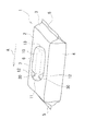
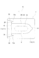
以下、本発明の一実施形態に係る包装体とそれに使用される蓋用ラベルについて図1〜図5を参酌しつつ説明する。図1に示す包装体1は、各種の被包装物が軟質包装材によってピロー包装等により包装された軟包体である。包装形態や種類、形状等は特には限定されないが、一例としては、ウエットティッシュが柔軟な包装袋によって密封包装されたウエットティッシュ包装体1が挙げられる。ウエットティッシュ包装体1の場合、内容物であるウエットティッシュ(ウエットシート)が略矩形に形成されて多数枚積層された状態で収容されており、従って、ウエットティッシュの積層体は略直方体形状であって、それがピロー包装されて形成された包装体1もまた略直方体形状となる。   Hereinafter, a package according to an embodiment of the present invention and a lid label used therefor will be described with reference to FIGS. A package 1 shown in FIG. 1 is a soft package in which various objects to be packaged are packaged by pillow packaging or the like with a soft packaging material. Although a packaging form, a kind, a shape, etc. are not specifically limited, As an example, the wet tissue package 1 by which the wet tissue was hermetically packaged by the flexible packaging bag is mentioned. In the case of the wet tissue package 1, the wet tissue (wet sheet), which is the contents, is formed in a substantially rectangular shape and stored in a stacked state. Therefore, the wet tissue laminate has a substantially rectangular parallelepiped shape. The package 1 formed by pillow-wrapping it also has a substantially rectangular parallelepiped shape.

従って、包装体1は略長方形の上面2とそれと対向した底面と、二対の側面3,4とを有している。二対の側面3,4のうち、一方は略長方形の上面2及び底面の長辺側に位置し他方は短辺側に位置する。短辺側の両側面3にはそれぞれ横シール部5が形成され、該横シール部5は側方に突出した状態にある。そして、包装体1の一面、具体的には上面2には内容物を取り出すための取り出し口6が形成されていて、その取り出し口6を再封可能に閉塞するための蓋用ラベル7が剥離可能且つ再貼着可能に貼着されている。取り出し口6は包装体1の上面2に予め設けられていてもよいし、上面2の略中央部における包装袋1に例えば円形状や楕円形状、矩形状、コの字状等の切り込み線が取り出し口6として形成され、蓋用ラベル7を剥離することによって切り込み線で囲まれた内側領域が蓋用ラベル7に貼着しつつ包装袋1から切離して切り込み線の形状に対応した取り出し口6が開口する構成であってもよい。尚、図示しないが、包装体1の底面には背貼り部(センターシール部)が形成されている。   Therefore, the package 1 has a substantially rectangular upper surface 2, a bottom surface facing the upper surface 2, and two pairs of side surfaces 3 and 4. Of the two pairs of side surfaces 3 and 4, one is positioned on the long side of the substantially rectangular top surface 2 and bottom surface, and the other is positioned on the short side. A lateral seal portion 5 is formed on each side surface 3 on the short side, and the lateral seal portion 5 is in a state of projecting sideways. And, on one side of the package 1, specifically the upper surface 2, a takeout port 6 for taking out the contents is formed, and the lid label 7 for closing the takeout port 6 so as to be resealable is peeled off. It is attached so that it can be reattached. The take-out port 6 may be provided in advance on the upper surface 2 of the package 1, and a cut line such as a circular shape, an elliptical shape, a rectangular shape, or a U-shape is formed on the packaging bag 1 in the substantially central portion of the upper surface 2. An inner region formed as a take-out port 6 and separated from the packaging bag 1 while the inner region surrounded by the cut line is attached to the cover label 7 by peeling off the cover label 7 and corresponds to the shape of the cut line May be configured to open. Although not shown, a back pasting portion (center seal portion) is formed on the bottom surface of the package 1.

取り出し口6の位置は好ましくは上面2の中央部である。また、取り出し口6の形状は任意であるが、包装体1の上面2が長方形であるためその長辺に沿って長い形状とすることが好ましい。蓋用ラベル7の形状は取り出し口6を覆うことができるものであればよいが、代表的には取り出し口6の形状に対応したものとされる。従って、蓋用ラベル7もまた包装体1の上面2の長辺に沿って長い形状とされ、例えば長円形とされ、その長手方向が剥離方向とされる。   The position of the take-out port 6 is preferably the central portion of the upper surface 2. Moreover, although the shape of the taking-out port 6 is arbitrary, since the upper surface 2 of the package 1 is a rectangle, it is preferable to make it a long shape along the long side. The lid label 7 may have any shape as long as it can cover the take-out port 6, but typically corresponds to the shape of the take-out port 6. Accordingly, the lid label 7 is also formed in a long shape along the long side of the upper surface 2 of the package 1, for example, an oval shape, and the longitudinal direction thereof is the peeling direction.

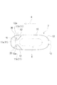
図2に蓋用ラベル7の概要を正面図で示している。蓋用ラベル7は、貼着状態で取り出し口6を覆うと共に、蓋用ラベル7の一端側を始端とし蓋用ラベル7の他端側を終端として剥離されて取り出し口6を開口させる開閉部10と、該開閉部10を支持する支持部11とを備えている。本実施形態では、蓋用ラベル7の一端側に開閉部10が位置し他端側に支持部11が位置している。そして、その境界付近に、蓋用ラベル7の剥離を止めるためのストッパー用切り込み線12が形成されている。即ち、蓋用ラベル7は、開閉部10と支持部11とからなり、その両部分を互いに区画するようにストッパー用切り込み線12が形成されている。   FIG. 2 shows an outline of the lid label 7 in a front view. The lid label 7 covers the take-out port 6 in a sticking state, and is opened and closed to open the take-out port 6 by being peeled off with the one end side of the lid label 7 as the starting end and the other end side of the lid label 7 as the end. And a support part 11 for supporting the opening / closing part 10. In this embodiment, the opening / closing part 10 is located on one end side of the lid label 7 and the support part 11 is located on the other end side. A stopper cut line 12 for stopping the peeling of the lid label 7 is formed in the vicinity of the boundary. That is, the lid label 7 includes an opening / closing part 10 and a support part 11, and a stopper cut line 12 is formed so as to partition both parts from each other.

図1及び図2に示している矢印Aは蓋用ラベル7の剥離方向を示している。後述する図6等においても矢印Aで蓋用ラベル7の剥離方向を示している。上述したように剥離方向は蓋用ラベル7の長手方向と一致しており、図中向かって右側である蓋用ラベル7の一端側が剥離方向の始端側となり、同じく向かって左側である蓋用ラベル7の他端側が剥離方向の終端側となる。従って、開閉部10は剥離方向の始端側に位置し、支持部11は剥離方向の終端側に位置している。開閉部10は、蓋用ラベル7の大部分の面積を占めていて取り出し口6を完全に覆ってそれを閉塞できる程度の大きさを有しており、その略中央部に取り出し口6が位置するように包装体1に貼着される。そして、その開閉部10を剥離、再貼着するように支持部11を支点として上下に回動させることにより、取り出し口6を閉じたり開いたりすることができる。蓋用ラベル7の一端即ち開閉部10の剥離方向の始端には、摘み部13が設けられている。該摘み部13は蓋用ラベル7の一端側の一領域の裏面を非接着部14とすることにより構成されており、摘み部13を摘むことで容易に剥離操作を開始できる。尚、非接着部14は非常に小さい力で剥離する弱接着のものも含む。また、図2に二点鎖線で示しているように摘み部13を剥離方向の始端側に向けて突出した形状としてもよく、その場合には、突出した摘み部13の裏面のみを非接着部14としてもよい。尚、使用状態を示している図4及び図5において摘み部13は裏面側から見た状態となっているが、そこでは摘み部13の裏面の非接着部14にはクロスハッチングを施している。また、図2及び図3において二点鎖線で示している仮想線15は、開閉部10と支持部11との間の仮想的な境界線であって蓋用ラベル7の幅方向に沿って延びており、開閉部10の剥離方向の終端となっている。   The arrow A shown in FIG.1 and FIG.2 has shown the peeling direction of the label 7 for lid | covers. In FIG. 6 and the like which will be described later, the peeling direction of the lid label 7 is indicated by an arrow A. As described above, the peeling direction coincides with the longitudinal direction of the lid label 7, and one end side of the lid label 7 on the right side in the figure is the starting end side in the peeling direction, and the lid label is also on the left side in the same way. The other end side of 7 is the end side in the peeling direction. Therefore, the opening / closing part 10 is located on the start side in the peeling direction, and the support part 11 is located on the terminal side in the peeling direction. The opening / closing part 10 occupies most of the area of the lid label 7 and has a size that can completely cover the takeout port 6 and close it, and the takeout port 6 is located at a substantially central part. It sticks to the package 1 as it does. Then, the take-out port 6 can be closed or opened by rotating up and down with the support portion 11 as a fulcrum so that the opening and closing portion 10 is peeled off and reattached. A knob portion 13 is provided at one end of the lid label 7, that is, at the start end of the opening / closing portion 10 in the peeling direction. The knob portion 13 is configured by setting the back surface of one region on one end side of the lid label 7 as a non-adhesive portion 14, and the peeling operation can be easily started by pinching the knob portion 13. Note that the non-bonded portion 14 includes a weakly bonded portion that peels off with a very small force. Further, as shown by a two-dot chain line in FIG. 2, the knob portion 13 may have a shape protruding toward the start end side in the peeling direction, and in that case, only the back surface of the protruding knob portion 13 is a non-adhesive portion. It may be 14. 4 and 5 showing the state of use, the knob portion 13 is viewed from the back side, but the non-adhered portion 14 on the back surface of the knob portion 13 is cross-hatched. . 2 and 3 is a virtual boundary line between the opening / closing part 10 and the support part 11 and extends along the width direction of the lid label 7. The opening / closing part 10 is the end in the peeling direction.

ストッパー用切り込み線12は、蓋用ラベル7の両側縁にそれぞれ形成されていて、開閉部10と支持部11とを区画するように形成されている。両ストッパー用切り込み線12は、互いに対称形状である。ストッパー用切り込み線12は、具体的には、図3に示しているように、蓋用ラベル7の側縁の所定位置を始点としてそこから蓋用ラベル7の内側に向けて延びており、その始点から全体として蓋用ラベル7の他端側に延びる順路部と、全体として蓋用ラベル7の一端側に戻る戻り部12aとから構成されている。順路部と戻り部12aとの境界点は、ストッパー用切り込み線12において最も蓋用ラベル7の他端側に位置する、即ち、剥離方向の終端側に位置する箇所であり、その点を最下流点20と称することにすると、順路部は、ストッパー用切り込み線12の始点から最下流点20までの部分であり、戻り部12aは、最下流点20からストッパー用切り込み線12の終点までの部分である。また、戻り部12aは、順路部に対してその蓋用ラベル7の側縁に近い外側に位置している。尚、二つの最下流点20同士を結んだ直線が上述した仮想線15である。   The stopper cut lines 12 are respectively formed on both side edges of the lid label 7 so as to partition the opening / closing part 10 and the support part 11. Both the stopper cut lines 12 are symmetrical to each other. Specifically, as shown in FIG. 3, the cut line 12 for the stopper extends from the predetermined position of the side edge of the lid label 7 to the inside of the lid label 7 as a starting point. It is comprised from the normal path part extended to the other end side of the label 7 for lids as a whole from the starting point, and the return part 12a which returns to the one end side of the label 7 for lids as a whole. The boundary point between the forward path portion and the return portion 12a is located at the most other end side of the lid label 7 on the stopper cut line 12, that is, located at the terminal end side in the peeling direction, and this point is the most downstream. When referring to the point 20, the forward path part is a part from the start point of the stopper cut line 12 to the most downstream point 20, and the return part 12 a is a part from the most downstream point 20 to the end point of the stopper cut line 12. It is. Moreover, the return part 12a is located on the outer side near the side edge of the lid label 7 with respect to the normal path part. The straight line connecting the two most downstream points 20 is the imaginary line 15 described above.

より詳細には、ストッパー用切り込み線12は、始点から蓋用ラベル7の内側且つ他端側に向けて傾斜して延びる傾斜状部21と、該傾斜状部21の終点から蓋用ラベル7の他端側に向けて剥離方向と略平行に直線状に延びる第一の直線状部22と、該第一の直線状部22の終点から最下流点20まで蓋用ラベル7の他端側且つ側縁側に向けて弧を描きつつ延びる第一の弧状部23と、最下流点20から蓋用ラベル7の側縁側且つ一端側に向けて弧を描きつつ延びる第二の弧状部24と、該第二の弧状部24の終点から蓋用ラベル7の一端側に向けて剥離方向と略平行に直線状に延びる第二の直線状部25とから構成されている。傾斜状部21は例えば45度程度の傾斜角度で蓋用ラベル7の内側且つ他端側に向けて傾斜して延びていて、ストッパー用切り込み線12の主要部分を構成している。傾斜状部21の終点は例えば蓋用ラベル7の全幅の略1/3程度のところに位置するが、この位置は一例であって種々であってよい。第一の直線状部22は、内側の直線状部であって、傾斜状部21よりも短いが、この長さも種々変更してよい。第一の弧状部23と第二の弧状部24は最下流点20を頂点として互いに連続していて代表的には円弧であり、例えばそれぞれ1/4円とされて二つ合わせて半円とされる。但し、第一の弧状部23や第二の弧状部24は、楕円弧等であってもよい。第二の直線状部25は、外側の直線状部であって、第一の直線状部22とは互いに平行関係にある。第二の直線状部25の長さも任意であるが、例えば、第一の直線状部22よりも短くすることが好ましい。傾斜状部21と第一の直線状部22と第一の弧状部23とから順路部が構成され、第二の弧状部24と第二の直線状部25とから戻り部12aが構成されている。また、上述したように、二つのストッパー用切り込み線12は互いに対称関係にあるため、順路部において、開閉部10の幅は、傾斜状部21では剥離方向に沿って徐々に狭くなっていき、第一の直線状部22では略一定であり、第一の弧状部23では剥離方向に沿って急激に広がっていく。   More specifically, the stopper cut line 12 extends from the starting point to the inside of the lid label 7 and to the other end side, and the inclined portion 21 extends from the end of the inclined portion 21 to the lid label 7. A first linear portion 22 extending linearly in a direction substantially parallel to the peeling direction toward the other end side, the other end side of the lid label 7 from the end point of the first linear portion 22 to the most downstream point 20; A first arc-shaped portion 23 extending while drawing an arc toward the side edge side, a second arc-shaped portion 24 extending while drawing an arc from the most downstream point 20 toward the side edge side and one end side of the lid label 7; The second linear portion 25 extends linearly from the end point of the second arcuate portion 24 toward the one end side of the lid label 7 in a straight line substantially parallel to the peeling direction. The inclined portion 21 extends at an inclination angle of about 45 degrees, for example, toward the inner side of the lid label 7 and toward the other end side, and constitutes a main portion of the stopper cut line 12. The end point of the inclined portion 21 is located, for example, at about 1/3 of the entire width of the lid label 7, but this position is an example and may be various. The first linear portion 22 is an inner linear portion and is shorter than the inclined portion 21, but the length may be variously changed. The first arc-shaped portion 23 and the second arc-shaped portion 24 are continuous with each other with the most downstream point 20 as the apex, and are typically arcs. Is done. However, the first arc-shaped portion 23 and the second arc-shaped portion 24 may be elliptical arcs or the like. The second linear portion 25 is an outer linear portion, and is parallel to the first linear portion 22. Although the length of the 2nd linear part 25 is also arbitrary, For example, it is preferable to make it shorter than the 1st linear part 22. FIG. The inclined portion 21, the first linear portion 22 and the first arc-shaped portion 23 constitute a forward path portion, and the second arc-shaped portion 24 and the second linear portion 25 constitute a return portion 12a. Yes. Further, as described above, since the two stopper cut lines 12 are in a symmetric relationship with each other, the width of the opening / closing part 10 is gradually narrowed along the peeling direction in the inclined part 21 in the forward path part, The first linear portion 22 is substantially constant, and the first arc-shaped portion 23 rapidly spreads along the peeling direction.

蓋用ラベル7には、戻り部12aから蓋用ラベル7の他端側の縁部まで、蓋用ラベル7を切離するための切離線30が形成されている。該切離線30は、ストッパー用切り込み線12の戻り部12aから蓋用ラベル7の他端側の縁部まで形成されている。切離線30の形状、構成は種々であってよいが、本実施形態では切断部31と非切断部とが交互に形成されたミシン目であって、ストッパー用切り込み線12の戻り部12aと連続していてそれとつながっていると共に蓋用ラベル7の縁部ともつながっている。図3に符号30aで示している箇所が切離線30の始点であって、符号30bで示している箇所が切離線30の終点であるが、切離線30の始点30aはストッパー用切り込み線12の戻り部12aに位置していて、切離線30の終点30bは蓋用ラベル7の縁部に位置している。切離線30の始点30aに対して終点30bは、蓋用ラベル7の他端側に位置すると共に蓋用ラベル7の幅方向外側に位置しており、従って、切離線30は全体として蓋用ラベル7の一端側から他端側に向けて幅方向外側に傾斜して延びている。尚、切離線30の始点30aはストッパー用切り込み線12の戻り部12aから若干離れてそれとは不連続になっていてもよく、また、切離線30の終点30bは蓋用ラベル7の縁部から若干離れて不連続の関係になっていてもよい。   A separating line 30 for separating the lid label 7 is formed on the lid label 7 from the return portion 12a to the edge on the other end side of the lid label 7. The separating line 30 is formed from the return part 12a of the stopper cutting line 12 to the edge part on the other end side of the lid label 7. The shape and configuration of the separation line 30 may be various, but in the present embodiment, the cut line 31 is a perforation formed alternately with the non-cut part, and is continuous with the return part 12 a of the stopper cut line 12. It is connected to the edge of the lid label 7 while being connected to it. In FIG. 3, the location indicated by reference numeral 30 a is the starting point of the separation line 30, and the location indicated by reference numeral 30 b is the end point of the separation line 30, but the starting point 30 a of the separation line 30 is the stop cutting line 12. Located at the return portion 12a, the end point 30b of the separation line 30 is located at the edge of the lid label 7. The end point 30b is located on the other end side of the lid label 7 and on the outer side in the width direction of the lid label 7 with respect to the start point 30a of the separation line 30. Therefore, the separation line 30 as a whole is a lid label. 7 extends from one end side to the other end side while inclining outward in the width direction. The starting point 30a of the separating line 30 may be slightly distant from the return part 12a of the stopper cutting line 12, and the end point 30b of the separating line 30 may be separated from the edge of the lid label 7. It may be a discontinuous relationship slightly apart.

切離線30は、より詳細には、戻り部12aのうちの第二の直線状部25から始まっている。即ち、切離線30の始点30aは戻り部12aの第二の直線状部25に位置している。切離線30は、その始点30aと終点30bとの間を直線状に結ぶように形成されていてもよいが、本実施形態では、ミシン目を構成している切断部31が始点30aと終点30bとを結ぶ仮想線に対して斜めに傾斜した構成となっている。切離線30は複数の切断部31を有しているが、そのうち最も始点30a側に位置する切断部31は戻り部12aの第二の直線状部25とつながっていてその第二の直線状部25から蓋用ラベル7の他端側且つ幅方向外側に向けて傾斜して延びている。尚、全ての切断部31は互いに平行に形成することが好ましい。また、最も終点30b側に位置する切断部31は、蓋用ラベル7の縁部に達している。更に、最も終点30b側に位置する切断部31を除く他の切断部31はその蓋用ラベル7の幅方向外側の端部から蓋用ラベル7の他端側に向けて延びる誘導部32を有していて、全体としてへの字状に折れ曲がった形状となっている。誘導部32の剥離方向の延長線上には、次の切断部31が傾斜して存在している。このように切断部31が蓋用ラベル7の他端側に向かう誘導部32を有していると、その誘導部32から次の切断部31へと容易に蓋用ラベル7の破断ラインが到達してスムーズに切離できる。   More specifically, the separation line 30 starts from the second linear portion 25 of the return portion 12a. That is, the starting point 30a of the separation line 30 is located at the second linear portion 25 of the return portion 12a. The separation line 30 may be formed so as to linearly connect the start point 30a and the end point 30b, but in the present embodiment, the cutting portion 31 constituting the perforation is the start point 30a and the end point 30b. It is the structure which inclined diagonally with respect to the virtual line which connects. The separating line 30 has a plurality of cutting portions 31, and the cutting portion 31 located closest to the starting point 30a is connected to the second linear portion 25 of the return portion 12a, and the second linear portion. 25 extends from the other end side of the lid label 7 and toward the outer side in the width direction. In addition, it is preferable to form all the cutting parts 31 in parallel with each other. Further, the cutting portion 31 located closest to the end point 30 b reaches the edge of the lid label 7. Further, the other cutting portions 31 except the cutting portion 31 positioned closest to the end point 30b have a guide portion 32 extending from the outer end in the width direction of the lid label 7 toward the other end side of the lid label 7. And as a whole, it has a shape that is bent into a round shape. On the extended line of the guide part 32 in the peeling direction, the next cut part 31 exists in an inclined manner. Thus, if the cutting part 31 has the guide part 32 which goes to the other end side of the lid label 7, the break line of the lid label 7 easily reaches from the guide part 32 to the next cutting part 31. And can be separated smoothly.

このような蓋用ラベル7の裏面は、剥離可能且つ再貼着可能な接着部16と、非接着部14とに区画され、摘み部13の裏面が非接着部14とされる。上述したように非接着部14には非常に小さい力で剥離する弱接着の状態を含むものとする。   The back surface of the lid label 7 is partitioned into a peelable and reattachable adhesive portion 16 and a non-adhesive portion 14, and the back surface of the knob 13 is a non-adhesive portion 14. As described above, the non-bonding portion 14 includes a weakly bonded state in which peeling is performed with a very small force.

ここで、蓋用ラベル7は、ラベル基材と該ラベル基材の裏面に積層された接着剤層とを有する。ラベル基材は、柔軟なシートであればその材質等は特には限定されず、種々の公知のものを用いることができる。ラベル基材としては、例えば、紙、不織布、合成紙、プラスチックフィルム等が挙げられ、単層構造であってもよいし、二層以上の多層構造であってもよい。特に、機械的強度に優れていて柔軟性も併せ持つことから、合成紙若しくはプラスチックフィルムの単層、又は合成紙若しくはプラスチックフィルムを含む積層体が好ましい。また、プラスチックフィルムとしては、例えばポリエチレンテレフタレートやポリ乳酸などのエステル系樹脂、ポリプロピレン等のオレフィン系樹脂、スチレン−ブタジエン共重合体等のスチレン系樹脂、環状オレフィン系樹脂、塩化ビニル系樹脂等の熱可塑性樹脂を含む延伸フィルム等を用いることができ、その中でも機械的強度に優れることから、これらの二軸延伸フィルムを用いることが好ましい。ポリプロピレンフィルムを使用することも好ましい。ラベル基材の厚さも特には限定されないが、合成紙又はプラスチックフィルムの単層からなる場合には、例えば25μm〜120μmであり、好ましくは30μm〜100μmである。また、ポリエチレンテレフタレートフィルムを使用することも好ましく、その場合、厚さは35〜75μmとすることが好ましい。   Here, the lid label 7 has a label base material and an adhesive layer laminated on the back surface of the label base material. The label base material is not particularly limited as long as it is a flexible sheet, and various known materials can be used. Examples of the label base material include paper, non-woven fabric, synthetic paper, plastic film and the like, and may have a single layer structure or a multilayer structure of two or more layers. In particular, since it is excellent in mechanical strength and has flexibility, a single layer of synthetic paper or plastic film, or a laminate including synthetic paper or plastic film is preferable. Examples of the plastic film include thermal resins such as ester resins such as polyethylene terephthalate and polylactic acid, olefin resins such as polypropylene, styrene resins such as styrene-butadiene copolymers, cyclic olefin resins, and vinyl chloride resins. A stretched film containing a plastic resin or the like can be used, and among these, it is preferable to use these biaxially stretched films because of excellent mechanical strength. It is also preferable to use a polypropylene film. The thickness of the label substrate is not particularly limited, but when it is composed of a single layer of synthetic paper or plastic film, it is, for example, 25 μm to 120 μm, preferably 30 μm to 100 μm. Moreover, it is also preferable to use a polyethylene terephthalate film, and in that case, the thickness is preferably 35 to 75 μm.

蓋用ラベル7のラベル基材は、透明であってもよいし不透明であってもよい。合成紙は、通常乳白色の不透明であるため、ラベル基材が合成紙を含む場合には不透明なものとなる。また、プラスチックフィルムは、通常透明であるため、白色ベタ印刷や銀色ベタ印刷を透明なプラスチックフィルムに施すことによって、不透明なラベル基材とすることができる。また、プラスチックフィルムに金属蒸着膜のような不透明な層を積層することによって不透明のラベル基材としてもよい。ラベル基材の表面又は裏面には必要に応じて所望の表示部(印刷層)を印刷により形成する。不透明なラベル基材を用いる場合にはその表面に表示部を設けることになる。   The label base material of the lid label 7 may be transparent or opaque. Synthetic paper is usually milky white and opaque, and therefore becomes opaque when the label substrate includes synthetic paper. In addition, since the plastic film is usually transparent, an opaque label substrate can be obtained by applying white solid printing or silver solid printing to the transparent plastic film. Moreover, it is good also as an opaque label base material by laminating | stacking an opaque layer like a metal vapor deposition film on a plastic film. A desired display part (printing layer) is formed by printing on the front surface or the back surface of the label base as necessary. When an opaque label base material is used, a display portion is provided on the surface.

接着剤層は各種の粘着剤により構成され、例えばアクリル系、ゴム系等の感圧型粘着剤を用いることができる。また、感熱性粘着剤を用いてもよい。接着剤層の厚さは、例えば10〜30μmである。接着剤層はラベル基材の裏面の全体に形成されており、該接着剤層の裏面全体のうちの一部にいわゆる「糊殺し」や「糊抑え」とも称されるマスキング層が形成されることによって、蓋用ラベル7の裏面が接着部16と非接着部14とに区画される。即ち、マスキング層が形成された部分は、マスキング層が形成されずに残った部分に比して接着力が小さくなる。従って、接着剤層の裏面のうちマスキング層が形成された部分が非接着部14となり、接着剤層の裏面のうちマスキング層が形成されずに残った部分が接着部16となる。マスキング層は、マスキング剤を用いて公知の印刷手法によって形成できる。マスキング剤としては、非粘着性であって紫外線により硬化する層を接着剤層の上に形成できるものが好ましく、紫外線硬化型インキ等が使用できる。但し、ラベル基材の裏面全体に接着剤層を形成するのではなく、接着部16に対応するラベル基材の裏面のみに接着剤層を形成し、非接着部14に対応するラベル基材の裏面には接着剤層を形成しないようにして、接着部16と非接着部14とを区画形成してもよい。   The adhesive layer is composed of various pressure-sensitive adhesives, and for example, acrylic or rubber pressure-sensitive pressure-sensitive adhesives can be used. A heat-sensitive adhesive may also be used. The thickness of the adhesive layer is, for example, 10 to 30 μm. The adhesive layer is formed on the entire back surface of the label base material, and a masking layer called “glue killing” or “glue suppression” is formed on a part of the entire back surface of the adhesive layer. As a result, the back surface of the lid label 7 is partitioned into an adhesive portion 16 and a non-adhesive portion 14. That is, the adhesive strength of the portion where the masking layer is formed is smaller than that of the portion remaining without the masking layer being formed. Accordingly, the portion of the back surface of the adhesive layer where the masking layer is formed becomes the non-adhesive portion 14, and the portion of the back surface of the adhesive layer where the masking layer is not formed becomes the adhesive portion 16. The masking layer can be formed by a known printing method using a masking agent. The masking agent is preferably non-tacky and can form a layer that is cured by ultraviolet rays on the adhesive layer, and ultraviolet curable ink or the like can be used. However, an adhesive layer is not formed on the entire back surface of the label base material, but an adhesive layer is formed only on the back surface of the label base material corresponding to the adhesive portion 16, and the label base material corresponding to the non-adhesive portion 14 is formed. The adhesive part 16 and the non-adhesive part 14 may be partitioned so as not to form an adhesive layer on the back surface.

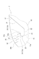
以上のように構成された包装体1の使用形態について説明すると、かかる包装体1は、図示しないケース(外箱)に収容しないでそのまま携帯用等として使用する場合と、ケースに収容して部屋用、詰め替え用等として使用する場合の何れにも適用可能である。包装体1をケースに収容しないでそのまま使用する場合には、図4のように、蓋用ラベル7の開閉部10を剥離して取り出し口6を開放させる。その際、ストッパー用切り込み線12が形成されていてその端部近傍に戻り部12aが形成されているので、蓋用ラベル7の剥離は途中で確実に停止する。特に、ストッパー用切り込み線12の端部近傍に戻り部12aが形成されているので、開閉部10の開閉操作を繰り返し行っても、ストッパー用切り込み線12から亀裂が蓋用ラベル7の他端側に向けて入ったり、ストッパー用切り込み線12の中途部で開閉部10が破断したりするということも防止される。   The usage pattern of the packaging body 1 configured as described above will be described. The packaging body 1 is used as it is for portable use without being housed in a case (outer box) (not shown), and is housed in a case. It can be applied to any use when used for refilling or refilling. When the packaging body 1 is used as it is without being accommodated in the case, the opening / closing portion 10 of the lid label 7 is peeled off to open the take-out port 6 as shown in FIG. At that time, since the stopper cut line 12 is formed and the return portion 12a is formed in the vicinity of the end portion, the peeling of the lid label 7 is reliably stopped halfway. In particular, since the return portion 12a is formed in the vicinity of the end portion of the stopper cut line 12, even if the opening / closing operation of the opening / closing portion 10 is repeatedly performed, the crack is broken from the stopper cut line 12 on the other end side of the lid label 7. It is also possible to prevent the opening / closing part 10 from breaking in the middle of the stopper cut line 12.

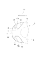
一方、包装体1をケースに収容して使用する場合には、包装体1をケースに収容しないでそのまま使用する場合と同様に、蓋用ラベル7を一端側から他端側に向けて剥離していく。蓋用ラベル7にはストッパー用切り込み線12が形成されていてその端部近傍には戻り部12aが設けられているので、開閉部10の剥離はその剥離方向の終端で一旦停止する。そして、続けてそこから更に力を入れて開閉部10を強く剥離方向に引っ張ると、開閉部10のみならず支持部11の一部まで剥離し始める。その結果、支持部11の剥離部分が戻り部12aまで達して、やがて切離線30の始点30aまで剥離部分が到達すると、切離線30は戻り部12a側から切離し始めて、やがて蓋用ラベル7の他端側の縁部まで完全に切離する。詳細には、切離線30の複数の切断部31のうちで最も始点30a側に位置する切断部31の誘導部32から二番目の切断部31へと破断ラインが走り、続けて、二番目の切断部31の誘導部32から三番目の切断部31へと破断ラインが走り、更に、三番目の切断部31の誘導部32から四番目の切断部31へと破断ラインが走って、蓋用ラベル7は、支持部11のうち切離線30の外側に位置する部分のみを残して包装体1から分離する。即ち、支持部11のうち両切離線30の間に位置する中央部分11aが開閉部10と一体となって包装体1から分離する一方、支持部11のうち両切離線30よりも外側に位置する一対の外側部分11bは包装体1にそのまま貼着された状態で残る。換言すれば、支持部11のうち両切離線30の間に位置する中央部分11aは開閉部10と共に包装体1から剥離除去される剥離除去部分であり、支持部11のうち両切離線30よりも外側に位置する一対の外側部分11bは包装体1に貼着状態のまま残る残存部分である。   On the other hand, when the package 1 is used while being accommodated in a case, the lid label 7 is peeled from one end side to the other end side in the same manner as when the package 1 is used without being accommodated in the case. To go. Since the stopper label 7 is formed in the lid label 7 and the return portion 12a is provided in the vicinity of the end portion thereof, the peeling of the opening / closing portion 10 is temporarily stopped at the end in the peeling direction. Then, when further force is applied from there and the opening / closing part 10 is pulled strongly in the peeling direction, not only the opening / closing part 10 but also a part of the support part 11 starts to peel. As a result, when the peeling portion of the support portion 11 reaches the return portion 12a and eventually reaches the starting point 30a of the separation line 30, the separation line 30 starts to separate from the return portion 12a side, and eventually the other of the label 7 for the lid Cut completely to the edge of the end. Specifically, a break line runs from the guide part 32 of the cutting part 31 located closest to the starting point 30a among the plurality of cutting parts 31 of the separation line 30 to the second cutting part 31, and then the second part A break line runs from the guide part 32 of the cutting part 31 to the third cut part 31, and further, a break line runs from the guide part 32 of the third cut part 31 to the fourth cut part 31 for the lid. The label 7 is separated from the package 1 leaving only the portion of the support 11 that is located outside the separation line 30. That is, the central portion 11 a located between the two separation lines 30 in the support portion 11 is separated from the packaging body 1 integrally with the opening / closing portion 10, while being located outside the two separation lines 30 in the support portion 11. The pair of outer portions 11b to be left remain attached to the package 1 as they are. In other words, the central portion 11 a located between the two separation lines 30 in the support portion 11 is a peeling removal portion that is peeled and removed from the packaging body 1 together with the opening / closing portion 10, and from the two separation lines 30 in the support portion 11. The pair of outer portions 11b positioned on the outer side are remaining portions remaining on the packaging body 1 while being stuck.

このように、包装体1をケースに収容して使用する場合においても、包装体1をケースに収容せずにそのまま使用する場合と同じ方向に剥離操作すればよく、操作がシンプルであって理解しやすい。即ち、使用者は、ケースの使用の有無によらず常に一方向に蓋用ラベル7を剥離すればよく、使用に際して剥離する向きを気にする必要がない。しかも、切離線30がストッパー用切り込み線12の戻り部12aから延びているので、包装体1をケースに入れずにそのまま使用する場合において不用意に切離線30が切離するおそれがない。即ち、仮に切離線30がストッパー用切り込み線12の順路部に形成されていると、開閉部10の開閉操作中に切離線30が切離し始める可能性がある。一方、ストッパー用切り込み線12の最下流点20よりも終点側に切離線30が位置している、即ち、切離線30の始点30aが戻り部12a又は戻り部12aから若干離れた箇所から延びていると、開閉部10の通常の開閉操作においてはストッパー用切り込み線12の最下流点20よりも終点側まで剥離が進まないため、切離線30の切離を防止することができるのである。   Thus, even when the package 1 is used while being accommodated in the case, it is sufficient to perform the peeling operation in the same direction as when the package 1 is used without being accommodated in the case, and the operation is simple and understandable. It's easy to do. That is, the user may always peel the lid label 7 in one direction regardless of whether the case is used or not, and does not need to worry about the direction of peeling in use. Moreover, since the cutting line 30 extends from the return portion 12a of the stopper cutting line 12, there is no possibility that the cutting line 30 will inadvertently cut off when the packaging body 1 is used without being put in the case. That is, if the separation line 30 is formed in the forward path portion of the stopper cutting line 12, the separation line 30 may start to be disconnected during the opening / closing operation of the opening / closing unit 10. On the other hand, the separation line 30 is located on the end point side of the most downstream point 20 of the stopper cutting line 12, that is, the starting point 30a of the separation line 30 extends from a part slightly away from the return part 12a or the return part 12a. In this case, in the normal opening / closing operation of the opening / closing part 10, the separation does not proceed to the end point side from the most downstream point 20 of the stopper cutting line 12, so that the separation line 30 can be prevented from being separated.

尚、本実施形態では、切離線30が合計四つの切断部31を有する構成であったが、切断部31の個数や切離線30の長さは任意であって、例えば、図6のように比較的短い切離線30であってもよく、切断部31が二つであってもよい。   In the present embodiment, the separating line 30 has a total of four cutting parts 31. However, the number of the cutting parts 31 and the length of the separating line 30 are arbitrary, for example, as shown in FIG. The cut line 30 may be relatively short, and the number of the cutting parts 31 may be two.

また、開閉部10の剥離方向の終端近傍に、他の部分よりも接着力が相対的に小さい弱接着部17を設けることも好ましい。弱接着部17の形状や構成は種々のものであってよいが、例えば、図6のように開閉部10の終端近傍の全幅に亘って帯状に形成することができる。その他、弱接着部17を単一あるいは複数の島状に形成してもよい。弱接着部17は他の部分よりも接着力が小さければよいが、代表的には、上述した非接着部14とすることができ、例えば接着層の裏面にマスキング層を積層することにより、摘み部13における非接着部14と共に同一工程で形成できる。   It is also preferable to provide a weak adhesive portion 17 having a relatively smaller adhesive force than other portions in the vicinity of the end of the opening / closing portion 10 in the peeling direction. Although the shape and structure of the weak adhesion part 17 may be various, for example, as shown in FIG. 6, it can be formed in a band shape over the entire width near the terminal end of the opening / closing part 10. In addition, the weak adhesion portion 17 may be formed in a single or a plurality of island shapes. The weakly bonded portion 17 only needs to have a lower adhesive force than other portions, but can be typically the non-adhered portion 14 described above. For example, by picking up a masking layer on the back surface of the adhesive layer, It can be formed in the same process together with the non-bonded portion 14 in the portion 13.

また更に、切離線30のミシン目形状も種々のものであってよく、例えば、図7のように、上述したような誘導部32を設けない切断部31の構成としてもよい。この図7のように切断部31が折れ曲がり部分のない一直線状のものであっても、図8に矢印付きの二点鎖線で示しているように個々の切断部31の終点から蓋用ラベル7の剥離方向に沿って仮想線33を引いたとき、その仮想線33が次の切断部31と交わるような配置になっていると、蓋用ラベル7の破断ラインが次の切断部31に確実に到達できる。   Furthermore, the perforation shape of the separating line 30 may be various. For example, as shown in FIG. 7, a configuration of the cutting part 31 that does not include the guide part 32 as described above may be employed. Even if the cutting part 31 is a straight line with no bent part as shown in FIG. 7, the label 7 for the lid is formed from the end point of each cutting part 31 as indicated by a two-dot chain line with an arrow in FIG. When the imaginary line 33 is drawn along the peeling direction, if the imaginary line 33 intersects with the next cutting part 31, the broken line of the lid label 7 is surely connected to the next cutting part 31. Can be reached.

また、切断部31は曲線状であってもよく、例えば、図9のように略S字状に湾曲した切断部31としてもよい。更に、図10のように、切断部31の終点に誘導部32を備えると共に始点にも誘導部32を備えて、全体として略Z字状に折れ曲がった形状としてもよい。   Moreover, the cutting part 31 may be curvilinear, for example, it is good also as the cutting part 31 curved in the substantially S shape like FIG. Furthermore, as shown in FIG. 10, the guide part 32 may be provided at the end point of the cutting part 31 and the guide part 32 may be provided at the start point, and the whole part may be bent into a substantially Z shape.

また更に、ストッパー用切り込み線12の形状や配置等も種々変更可能であって、上述したように蓋用ラベル7の両側縁からそれぞれ内側に延びる形状の他、例えば、蓋用ラベル7の側縁から内側に離れた位置に形成するようにしてもよい。蓋用ラベル7の面内にストッパー用切り込み線12を形成する構成も種々あるが、例えば、図11のように、支持部11側から開閉部10側に向けて突出する突片部を形成するようにストッパー用切り込み線12を形成してもよい。このストッパー用切り込み線12は、蓋用ラベル7の他端側を両端として蓋用ラベル7の他端側に開口する半円状あるいはU字状に形成された主部26(順路部)を備えると共に、その両端に戻り部12aを備え、戻り部12aは、主部26の内側に周り込むように形成されている。そして、両戻り部12aから蓋用ラベル7の他端側の縁部までそれぞれ切離線30が形成されている。かかる蓋用ラベル7を使用した包装体1においてそれをケースに入れて使用する場合には、開閉部10の剥離がストッパー用切り込み線12によって一旦停止した後、更に力を入れて開閉部10を引っ張ることで二本の切離線30が破断して、包装体1には、支持部11の一部(ストッパー用切り込み線12と切離線30と蓋用ラベル7の他端側の縁部によって囲まれた領域11b)が残存部分として島状に残り、支持部11の他の部分11aは剥離除去部分として開閉部10と共に包装体1から剥離除去される。尚、図11のような形状のストッパー用切り込み線12を蓋用ラベル7の幅方向に間隔をあけて複数形成してもよい。   Furthermore, the shape and arrangement of the stopper cut line 12 can be variously changed. As described above, in addition to the shape extending inward from both side edges of the lid label 7, for example, the side edge of the lid label 7. You may make it form in the position away from the inside. There are various configurations in which the stopper cut line 12 is formed in the surface of the lid label 7. For example, as shown in FIG. 11, a projecting piece projecting from the support portion 11 side toward the opening / closing portion 10 side is formed. In this way, the stopper cut line 12 may be formed. The stopper cut line 12 includes a main portion 26 (forward path portion) formed in a semicircular shape or a U shape that opens to the other end side of the lid label 7 with the other end side of the lid label 7 as both ends. In addition, return portions 12 a are provided at both ends thereof, and the return portions 12 a are formed so as to go around the inside of the main portion 26. A separation line 30 is formed from both return portions 12a to the edge on the other end side of the lid label 7 respectively. When the packaging body 1 using the lid label 7 is used in a case, after the peeling of the opening / closing portion 10 is temporarily stopped by the stopper cut line 12, further force is applied to open the opening / closing portion 10. The two separation lines 30 are broken by pulling, and the package body 1 is surrounded by a part of the support portion 11 (the cut line 12 for the stopper, the separation line 30 and the edge on the other end side of the lid label 7). The remaining region 11b is left in the shape of an island as a remaining portion, and the other portion 11a of the support portion 11 is peeled and removed from the package 1 together with the opening / closing portion 10 as a peeling removal portion. A plurality of stopper cut lines 12 having a shape as shown in FIG. 11 may be formed at intervals in the width direction of the lid label 7.

また、図12のように、蓋用ラベル7の周縁部を支持部11から構成し、その内側に開閉部10が位置する構成としてもよい。蓋用ラベル7の面内に、蓋用ラベル7の他端側に開口するU字状あるいはコの字状のストッパー用切り込み線12を形成する。即ち、ストッパー用切り込み線12は、蓋用ラベル7の他端側に開口するU字状あるいはコの字状の主部26(順路部)を備え、その主部26の両端にそれぞれ外向きに延びる戻り部12aを備える。このようにストッパー用切り込み線12を形成することにより、その外側が支持部11となり、内側が開閉部10となって、開閉部10は蓋用ラベル7の一端側を始端とし他端側を終端として剥離される。該開閉部10の剥離方向の始端には摘み部13が突設され、その摘み部13もストッパー用切り込み線12によって区画形成される。かかる蓋用ラベル7を使用した包装体1においてそれをケースに入れて使用する場合、支持部11のうち開閉部10の外側に位置する部分11bが包装体1に残存部分として残り、両切離線30の内側に位置する部分11aは剥離除去部分として開閉部10と共に包装体1から剥離除去される。   Moreover, as shown in FIG. 12, the peripheral part of the lid label 7 may be constituted by the support part 11, and the opening / closing part 10 may be located inside thereof. A U-shaped or U-shaped stopper cut line 12 that opens to the other end of the lid label 7 is formed in the surface of the lid label 7. That is, the stopper cut line 12 includes a U-shaped or U-shaped main portion 26 (forward path portion) that opens on the other end side of the lid label 7, and outwards at both ends of the main portion 26. A return portion 12a is provided. By forming the stopper cut line 12 in this way, the outer side becomes the support part 11, the inner side becomes the opening / closing part 10, and the opening / closing part 10 ends at one end side of the lid label 7 and ends at the other end side. As exfoliated. A knob 13 protrudes from the start end of the opening / closing part 10 in the peeling direction, and the knob 13 is also defined by a cut line 12 for stopper. When the packaging body 1 using the lid label 7 is used in a case, a portion 11b of the support portion 11 located outside the opening / closing portion 10 remains as a remaining portion in the packaging body 1, and the two separating lines. The part 11a located inside 30 is peeled and removed from the package 1 together with the opening / closing part 10 as a peeled and removed part.

1 包装体
2 上面
3 短辺側の側面
4 長辺側の側面
5 横シール部
6 取り出し口
7 蓋用ラベル
10 開閉部
11 支持部
11a 中央部分(剥離除去部分)
11b 外側部分(残存部分)
12 ストッパー用切り込み線
12a 戻り部
13 摘み部
14 非接着部
15 仮想線(境界線)
16 接着部
17 弱接着部
20 最下流点
21 傾斜状部
22 第一の直線状部
23 第一の弧状部
24 第二の弧状部
25 第二の直線状部
26 主部(順路部)
30 切離線
30a 始点
30b 終点
31 切断部
32 誘導部
33 仮想線
A 剥離方向
DESCRIPTION OF SYMBOLS 1 Packing body 2 Upper surface 3 Side surface on the short side 4 Side surface on the long side 5 Horizontal seal part 6 Taking out port 7 Cover label 10 Opening / closing part 11 Support part 11a Central part (peeling removal part)
11b Outer part (remaining part)
12 Stop line 12a for stopper Return part 13 Knob part 14 Non-adhesive part 15 Virtual line (boundary line)
16 Adhesive part 17 Weakly adhering part 20 Most downstream point 21 Inclined part 22 First linear part 23 First arc part 24 Second arc part 25 Second linear part 26 Main part (forward part)
30 Cutting line 30a Start point 30b End point 31 Cutting part 32 Guide part 33 Virtual line A Peeling direction

Claims (4)

包装体の取り出し口を開閉自在に閉塞すべく包装体に剥離可能且つ再貼着可能に貼着され、貼着状態で取り出し口を覆うと共に、蓋用ラベルの一端側を始端側とし蓋用ラベルの他端側を終端側として剥離されて取り出し口を開放する開閉部と、該開閉部を支持する支持部とを備え、開閉部と支持部とを区画するためのストッパー用切り込み線が形成され、該ストッパー用切り込み線は、蓋用ラベルの一端側からストッパー用切り込み線において最も蓋用ラベルの他端側の位置である最下流点まで延びる順路部と、前記最下流点から蓋用ラベルの一端側に向けてストッパー用切り込み線の終点まで延びる戻り部とを有し、
戻り部から蓋用ラベルの他端側の縁部まで切離するための切離線が形成されており、切離線の始点は、戻り部のうち、前記最下流点よりもストッパ用切り込み線の終点側の箇所に位置していて、切離線は、戻り部と連続しており、切離線は、蓋用ラベルの一端側から他端側に向けて幅方向外側に傾斜していることを特徴とする蓋用ラベル。
Covering the take-out port in a stuck state, covering the take-out port in a stuck state so that the take-out port of the package can be freely opened and closed, and covering the take-out port with the cover label as the start side. An opening / closing part that is peeled off with the other end side of the opening as an end side to open the outlet and a support part that supports the opening / closing part, and a cut line for a stopper for partitioning the opening / closing part from the support part The stopper cut line extends from one end side of the lid label to the most downstream point that is the position on the other end side of the lid label at the stopper cut line, and the lid label from the most downstream point to the lid label. A return portion extending toward the end of the cut line for the stopper toward one end side,
A separation line for separating from the return portion to the edge on the other end side of the lid label is formed, and the start point of the separation line is the end point of the stopper cut line from the most downstream point of the return portion. be located at a position of the side, separating lines, a back portion are continuous, separating lines, and being inclined outward in the width direction toward the other end from one end of the label cover The label for the lid.
戻り部は、最下流点から蓋用ラベルの一端側に向けて弧を描きつつ延びる弧状部と、該弧状部の終点から蓋用ラベルの一端側に向けて直線状に延びる直線状部とを備え、切離線の始点は戻り部の直線状部に位置している請求項1記載の蓋用ラベル。The return portion includes an arc-shaped portion extending while drawing an arc from the most downstream point toward one end side of the lid label, and a linear portion extending linearly from the end point of the arc-shaped portion toward one end side of the lid label. 2. The lid label according to claim 1, wherein the start point of the separation line is located on the linear portion of the return portion. 開閉部の剥離方向の終端近傍に、接着力が相対的に小さい弱接着部が設けられている請求項1又は2記載の蓋用ラベル。 Near the end of the peeling direction of the opening portion, claim 1 or 2 for the cover label according weakly joined portion adhesive force is relatively small is provided. 請求項1乃至3の何れかに記載の蓋用ラベルが貼着されていることを特徴とする包装体。 A package, wherein the lid label according to any one of claims 1 to 3 is attached.
JP2014194337A 2014-09-24 2014-09-24 Lid label and package Active JP6566621B2 (en)

Priority Applications (1)

Application Number Priority Date Filing Date Title
JP2014194337A JP6566621B2 (en) 2014-09-24 2014-09-24 Lid label and package

Applications Claiming Priority (1)

Application Number Priority Date Filing Date Title
JP2014194337A JP6566621B2 (en) 2014-09-24 2014-09-24 Lid label and package

Publications (2)

Publication Number Publication Date
JP2016064846A JP2016064846A (en) 2016-04-28
JP6566621B2 true JP6566621B2 (en) 2019-08-28

Family

ID=55804935

Family Applications (1)

Application Number Title Priority Date Filing Date
JP2014194337A Active JP6566621B2 (en) 2014-09-24 2014-09-24 Lid label and package

Country Status (1)

Country Link
JP (1) JP6566621B2 (en)

Family Cites Families (8)

* Cited by examiner, † Cited by third party
Publication number Priority date Publication date Assignee Title
JPS62139975U (en) * 1986-02-28 1987-09-03
IT1252204B (en) * 1991-12-12 1995-06-05 Fin Omet S R L SEALING CLOSURE DEVICE FOR HUMIDIFIED MATERIAL DISPENSERS.
JP3916296B2 (en) * 1997-07-02 2007-05-16 ユニ・チャーム株式会社 Opening structure of the package
US6616334B2 (en) * 2001-11-30 2003-09-09 Playtex Products, Inc. Die cut resealable flap
JP4808005B2 (en) * 2005-10-31 2011-11-02 ユニ・チャーム株式会社 Double package
EP2336046B1 (en) * 2009-12-18 2012-06-27 The Procter & Gamble Company Flexible container and reusable closure element
JP5836795B2 (en) * 2011-12-27 2015-12-24 凸版印刷株式会社 Sealed label and packaging container
JP6171196B2 (en) * 2012-06-11 2017-08-02 株式会社フジシール Lid, lid with shape-retaining sheet, and package

Also Published As

Publication number Publication date
JP2016064846A (en) 2016-04-28

Similar Documents

Publication Publication Date Title
JP4808005B2 (en) Double package
JP4671675B2 (en) Easy-open packaging
JP2007314248A (en) Tamper-evident resealable closure
JP5836795B2 (en) Sealed label and packaging container
JP5976287B2 (en) Packaging body and opening / closing lid of packaging body
JP5732303B2 (en) Sealed label and packaging container
JP2008239187A (en) Easy-to-open gusset bag
JP6292501B2 (en) Sealed label and packaging container
JP6566621B2 (en) Lid label and package
JP6017116B2 (en) Sealed label and packaging container
JP2016064863A (en) Package body
JP2012081967A (en) Packaging bag with resealing function
JP6230834B2 (en) Integrated package
US11167901B2 (en) Flexible resealable packages
JP2011195147A (en) Wet tissue packaging bag
JP2015137112A (en) Binding tack label
JP6534841B2 (en) Lid label and package
JP2016108004A (en) Package
JP7422381B2 (en) Packaging material for rice balls
JP6914797B2 (en) Package
JP2017007669A (en) Packaging bag
JP2020083476A (en) Bag for sandwich packing
JP6421518B2 (en) Package
JP2023170153A (en) Lid label and package with lid label
JP2013169995A (en) Self-standing packaging bag

Legal Events

Date Code Title Description
A621 Written request for application examination

Free format text: JAPANESE INTERMEDIATE CODE: A621

Effective date: 20170809

A977 Report on retrieval

Free format text: JAPANESE INTERMEDIATE CODE: A971007

Effective date: 20180606

A131 Notification of reasons for refusal

Free format text: JAPANESE INTERMEDIATE CODE: A131

Effective date: 20180615

A521 Request for written amendment filed

Free format text: JAPANESE INTERMEDIATE CODE: A523

Effective date: 20180806

A131 Notification of reasons for refusal

Free format text: JAPANESE INTERMEDIATE CODE: A131

Effective date: 20190118

A521 Request for written amendment filed

Free format text: JAPANESE INTERMEDIATE CODE: A523

Effective date: 20190311

TRDD Decision of grant or rejection written
A01 Written decision to grant a patent or to grant a registration (utility model)

Free format text: JAPANESE INTERMEDIATE CODE: A01

Effective date: 20190712

A61 First payment of annual fees (during grant procedure)

Free format text: JAPANESE INTERMEDIATE CODE: A61

Effective date: 20190730

R150 Certificate of patent or registration of utility model

Ref document number: 6566621

Country of ref document: JP

Free format text: JAPANESE INTERMEDIATE CODE: R150

R250 Receipt of annual fees

Free format text: JAPANESE INTERMEDIATE CODE: R250

R250 Receipt of annual fees

Free format text: JAPANESE INTERMEDIATE CODE: R250