JP6566288B2 - Image forming apparatus - Google Patents
Image forming apparatus Download PDFInfo
- Publication number
- JP6566288B2 JP6566288B2 JP2014221465A JP2014221465A JP6566288B2 JP 6566288 B2 JP6566288 B2 JP 6566288B2 JP 2014221465 A JP2014221465 A JP 2014221465A JP 2014221465 A JP2014221465 A JP 2014221465A JP 6566288 B2 JP6566288 B2 JP 6566288B2
- Authority
- JP
- Japan
- Prior art keywords
- output
- image
- toner
- reference value
- adhesion amount
- Prior art date
- Legal status (The legal status is an assumption and is not a legal conclusion. Google has not performed a legal analysis and makes no representation as to the accuracy of the status listed.)
- Active
Links
Images


Classifications
-
- G—PHYSICS
- G03—PHOTOGRAPHY; CINEMATOGRAPHY; ANALOGOUS TECHNIQUES USING WAVES OTHER THAN OPTICAL WAVES; ELECTROGRAPHY; HOLOGRAPHY
- G03G—ELECTROGRAPHY; ELECTROPHOTOGRAPHY; MAGNETOGRAPHY
- G03G15/00—Apparatus for electrographic processes using a charge pattern
- G03G15/55—Self-diagnostics; Malfunction or lifetime display
- G03G15/553—Monitoring or warning means for exhaustion or lifetime end of consumables, e.g. indication of insufficient copy sheet quantity for a job
- G03G15/556—Monitoring or warning means for exhaustion or lifetime end of consumables, e.g. indication of insufficient copy sheet quantity for a job for toner consumption, e.g. pixel counting, toner coverage detection or toner density measurement
-
- G—PHYSICS
- G03—PHOTOGRAPHY; CINEMATOGRAPHY; ANALOGOUS TECHNIQUES USING WAVES OTHER THAN OPTICAL WAVES; ELECTROGRAPHY; HOLOGRAPHY
- G03G—ELECTROGRAPHY; ELECTROPHOTOGRAPHY; MAGNETOGRAPHY
- G03G15/00—Apparatus for electrographic processes using a charge pattern
- G03G15/06—Apparatus for electrographic processes using a charge pattern for developing
- G03G15/065—Arrangements for controlling the potential of the developing electrode
-
- G—PHYSICS
- G03—PHOTOGRAPHY; CINEMATOGRAPHY; ANALOGOUS TECHNIQUES USING WAVES OTHER THAN OPTICAL WAVES; ELECTROGRAPHY; HOLOGRAPHY
- G03G—ELECTROGRAPHY; ELECTROPHOTOGRAPHY; MAGNETOGRAPHY
- G03G15/00—Apparatus for electrographic processes using a charge pattern
- G03G15/14—Apparatus for electrographic processes using a charge pattern for transferring a pattern to a second base
- G03G15/16—Apparatus for electrographic processes using a charge pattern for transferring a pattern to a second base of a toner pattern, e.g. a powder pattern, e.g. magnetic transfer
- G03G15/1665—Apparatus for electrographic processes using a charge pattern for transferring a pattern to a second base of a toner pattern, e.g. a powder pattern, e.g. magnetic transfer by introducing the second base in the nip formed by the recording member and at least one transfer member, e.g. in combination with bias or heat
- G03G15/167—Apparatus for electrographic processes using a charge pattern for transferring a pattern to a second base of a toner pattern, e.g. a powder pattern, e.g. magnetic transfer by introducing the second base in the nip formed by the recording member and at least one transfer member, e.g. in combination with bias or heat at least one of the recording member or the transfer member being rotatable during the transfer
- G03G15/1675—Apparatus for electrographic processes using a charge pattern for transferring a pattern to a second base of a toner pattern, e.g. a powder pattern, e.g. magnetic transfer by introducing the second base in the nip formed by the recording member and at least one transfer member, e.g. in combination with bias or heat at least one of the recording member or the transfer member being rotatable during the transfer with means for controlling the bias applied in the transfer nip
-
- G—PHYSICS
- G03—PHOTOGRAPHY; CINEMATOGRAPHY; ANALOGOUS TECHNIQUES USING WAVES OTHER THAN OPTICAL WAVES; ELECTROGRAPHY; HOLOGRAPHY
- G03G—ELECTROGRAPHY; ELECTROPHOTOGRAPHY; MAGNETOGRAPHY
- G03G15/00—Apparatus for electrographic processes using a charge pattern
- G03G15/50—Machine control of apparatus for electrographic processes using a charge pattern, e.g. regulating differents parts of the machine, multimode copiers, microprocessor control
- G03G15/5054—Machine control of apparatus for electrographic processes using a charge pattern, e.g. regulating differents parts of the machine, multimode copiers, microprocessor control by measuring the characteristics of an intermediate image carrying member or the characteristics of an image on an intermediate image carrying member, e.g. intermediate transfer belt or drum, conveyor belt
- G03G15/5058—Machine control of apparatus for electrographic processes using a charge pattern, e.g. regulating differents parts of the machine, multimode copiers, microprocessor control by measuring the characteristics of an intermediate image carrying member or the characteristics of an image on an intermediate image carrying member, e.g. intermediate transfer belt or drum, conveyor belt using a test patch
Landscapes
- Physics & Mathematics (AREA)
- General Physics & Mathematics (AREA)
- Engineering & Computer Science (AREA)
- Microelectronics & Electronic Packaging (AREA)
- Control Or Security For Electrophotography (AREA)
Description
本発明は、画像形成装置に関するものである。 The present invention relates to an image forming apparatus.
従来、回転体の回転姿勢を検知した結果と、作像手段によって作像した濃度ムラ検知用トナー像の画像濃度ムラを検知した結果とに基づいて、電源からの出力を所定のパターンに従って変化させるための出力パターンデータを構築する画像形成装置が知られている。 Conventionally, the output from the power source is changed according to a predetermined pattern based on the result of detecting the rotation posture of the rotating body and the result of detecting the image density unevenness of the density unevenness detecting toner image formed by the image forming means. There is known an image forming apparatus for constructing output pattern data.
例えば、特許文献1に記載の画像形成装置は、大きな環境変動を検知したタイミングなどの所定のタイミングで、回転体たる感光体の回転姿勢を回転姿勢検知手段たるロータリーエンコーダーによって検知しながら、感光体上に濃度ムラ検知用トナー像を作像する。そして、その濃度ムラ検知用トナー像を中間転写ベルトに転写した後、反射型フォトセンサーにより、その濃度ムラ検知用トナー像において感光体の回転周期で発生している画像濃度ムラを把握する。この画像濃度ムラは、感光体の偏心や外形歪みに起因して感光体と現像装置の現像スリーブとの間の現像ギャップが感光体の回転周期で変動することによって発生するものである。かかる画像濃度ムラを把握したら、それを打ち消し得る現像バイアスの出力パターンを生起せしめるための出力パターンデータを構築する。その後、ユーザーの命令に基づく画像を形成する際に、現像バイアスを前述の出力パターンデータに従って変化させることで、感光体の回転周期に同期する画像濃度ムラの発生を抑えることができるとしている。
For example, the image forming apparatus described in
しかしながら、かかる構成においては、現像バイアスを出力する現像電源の出力上限や出力下限に起因して、感光体の回転周期で発生する画像濃度ムラを抑えることができなくなるおそれがあった。例えば、現像バイアスを−700[V]〜−500[V]の範囲で変化させたいにもかかわらず、電源の出力上限が−650[V]であったとする。この場合、感光体の一周期における所定の期間内で、現像バイアスを−651[V]から−700[V]まで変化させた後に−651[V]まで戻すべきであるにもかかわらず、一定の−650[V]を出力せざるを得なくなる。そして、その期間内に、画像濃度ムラの発生を抑えることができなくなってしまう。 However, in such a configuration, there is a possibility that image density unevenness that occurs in the rotation cycle of the photosensitive member cannot be suppressed due to the output upper limit and output lower limit of the developing power source that outputs the developing bias. For example, it is assumed that the upper limit of the output of the power supply is −650 [V] although it is desired to change the developing bias in the range of −700 [V] to −500 [V]. In this case, the development bias is changed from −651 [V] to −700 [V] and then returned to −651 [V] within a predetermined period in one cycle of the photosensitive member, but is constant. -650 [V] must be output. Then, the occurrence of image density unevenness cannot be suppressed within that period.
現像バイアスを電源の出力上限よりも大きく変化させたい場合だけでなく、現像バイアスを電源の出力下限よりも小さく変化させたい場合にも、同様にして、感光体の一周期における所定の期間内に画像濃度ムラの発生を抑えることができなくなってしまう。 In the same way, not only when the development bias is changed to be larger than the output upper limit of the power supply but also when the development bias is changed to be smaller than the output lower limit of the power supply, similarly, within a predetermined period in one cycle of the photosensitive member. It becomes impossible to suppress the occurrence of uneven image density.
なお、画像形成装置においては、感光体とは異なる回転体の回転周期で画像濃度ムラを発生させることもある。例えば、感光体を一様に帯電させる帯電ローラ、感光体上の静電潜像を現像する現像スリーブ、感光体や中間転写体に当接して転写ニップを形成する転写ローラなどの回転体の回転周期に同期する画像濃度ムラである。それらの画像濃度ムラは、帯電ローラの周方向の電気抵抗ムラ、現像スリーブの偏心や外形歪み、転写ローラの周方向の電気抵抗ムラなどに起因して発生する。かかる画像濃度ムラの発生を抑えるために、帯電バイアス、現像バイアス、転写バイアスなどの出力を出力パターンデータに従って変化させる場合にも、同様に、電源の出力上限や出力下限に起因して画像濃度ムラを抑えることが困難になってしまうおそれがある。 In the image forming apparatus, image density unevenness may occur at a rotation cycle of a rotating body different from the photosensitive body. For example, a rotating roller such as a charging roller that uniformly charges the photosensitive member, a developing sleeve that develops an electrostatic latent image on the photosensitive member, or a transfer roller that contacts the photosensitive member or an intermediate transfer member to form a transfer nip. This is image density unevenness synchronized with the period. Such image density unevenness is caused by uneven electrical resistance in the circumferential direction of the charging roller, eccentricity or external distortion of the developing sleeve, uneven electrical resistance in the circumferential direction of the transfer roller, and the like. In order to suppress the occurrence of such image density unevenness, when the output of the charging bias, the developing bias, the transfer bias, etc. is changed according to the output pattern data, the image density unevenness is similarly caused by the output upper limit and output lower limit of the power source. There is a risk that it will be difficult to suppress this.
上述した課題を解決するために、本発明は、潜像担持体の移動する表面を帯電手段によって帯電し、帯電後の前記潜像担持体の表面に潜像書込手段によって潜像を書き込み、現像手段によって前記潜像を現像してトナー像を作像する作像手段と、前記潜像担持体上のトナー像を、直接あるいは中間転写体を介して記録シートに転写する転写手段と、回転周期で画像濃度ムラを発生させる回転可能な回転体と、前記回転体の回転姿勢を検知する回転姿勢検知手段と、前記作像手段によって作像されたトナー像のトナー付着量を検知する付着量検知手段と、少なくとも前記帯電手段に供給する帯電バイアス用の電圧を出力する帯電電源及び前記現像手段の現像剤担持体に供給する現像バイアス用の電圧を出力する現像電源を含む、トナー像の作像から転写までの過程における所定のプロセスに寄与する電圧を出力する電源と、前記作像手段によって作像した濃度ムラ検知用トナー像のトナー付着量を前記付着量検知手段によって検知した結果、及び前記濃度ムラ検知用トナー像を作像する際の前記回転姿勢検知手段による検知結果に基づいて前記電源から出力される電圧を変化させるための出力パターンデータを構築する構築処理、前記電源から出力される電圧を前記回転姿勢検知手段による検知結果及び前記出力パターンデータに基づいて変化させながら前記プロセスを実行する出力変化処理、並びに、前記作像手段によって互いに異なる作像条件で作像した複数のトナー付着量検知用トナー像のトナー付着量を前記付着量検知手段によって検知した結果に基づいて前記電源からの出力の基準値を決定する基準値決定処理を実施する制御手段とを備える画像形成装置において、前記出力パターンデータの最大値が前記電源の出力上限値を超えるか、又は、前記出力パターンデータの最小値が前記電源の出力下限値を下回るという条件が具備されたことに基づいて、前記基準値決定処理で前記基準値を決定する際に参照する目標トナー付着量、又は前記基準値決定処理で決定した基準値を補正する補正処理を実施するように、前記制御手段を構成したことを特徴とするものである。 In order to solve the above-described problems, the present invention charges the moving surface of the latent image carrier by charging means, writes a latent image on the surface of the latent image carrier after charging by latent image writing means, An image forming unit that develops the latent image by a developing unit to form a toner image, a transfer unit that transfers the toner image on the latent image carrier directly or via an intermediate transfer member, and a rotation A rotatable rotator that causes image density unevenness in a cycle, a rotation attitude detection unit that detects a rotation attitude of the rotator, and an adhesion amount that detects a toner adhesion amount of a toner image formed by the imaging unit A toner image producing system comprising: a detecting unit; a charging power source that outputs at least a charging bias voltage supplied to the charging unit; and a developing power source that outputs a developing bias voltage supplied to the developer carrier of the developing unit. image A power source that outputs a voltage that contributes to a predetermined process in the process from transfer to transfer, a result of detection of the toner adhesion amount of the density unevenness detection toner image formed by the imaging means by the adhesion amount detection means, and A construction process for constructing output pattern data for changing a voltage output from the power supply based on a detection result by the rotation posture detection means when forming a density unevenness detection toner image, and output from the power supply Output change processing for executing the process while changing the voltage based on the detection result by the rotation posture detection means and the output pattern data, and attachment of a plurality of toners imaged under different image forming conditions by the image forming means Based on the result of detection of the toner adhesion amount of the toner image for amount detection by the adhesion amount detection means, the output from the power source is detected. In the image forming apparatus and a control means for performing a reference value determining process for determining a reference value of, or the maximum value of the output pattern data exceeds the output upper limit value of the power supply, or the minimum value of the output pattern data determined but based on the condition that falls below the output lower limit value of the power supply is provided, the target toner adhesion amount referred to when determining the reference value in the reference value determination process, or by the reference value determining process The control means is configured to perform a correction process for correcting the reference value.
本発明によれば、出力パターンデータに従って電源からの出力を変化させる構成において、電源の出力上限や出力下限にかかわらず画像濃度ムラの発生を確実に抑えることができる。 According to the present invention, in the configuration in which the output from the power supply is changed according to the output pattern data, it is possible to reliably suppress the occurrence of image density unevenness regardless of the output upper limit or output lower limit of the power supply.
以下、本発明を適用した画像形成装置として、電子写真方式のフルカラー複写機(以下、単に複写機という)の実施形態について説明する。まず、実施形態に係る複写機の基本的な構成について説明する。図1は、実施形態に係る複写機を示す概略構成図である。同図において、複写機は、記録シートに画像を形成する画像形成部100、画像形成部100に対して記録シート5を供給する給紙装置200、原稿の画像を読み取るスキャナ300などを備えている。また、スキャナ300の上部に取り付けられた原稿自動搬送装置(ADF)400なども備えている。画像形成部100には、記録シート5を手差しでセットするための手差しトレイ6や、画像形成済みの記録シート5をスタックするためのスタックトレイ7などが設けられている。
Hereinafter, an embodiment of an electrophotographic full-color copying machine (hereinafter simply referred to as a copying machine) will be described as an image forming apparatus to which the present invention is applied. First, a basic configuration of the copying machine according to the embodiment will be described. FIG. 1 is a schematic configuration diagram illustrating a copying machine according to an embodiment. In FIG. 1, the copying machine includes an
図2は、画像形成部100を拡大して示す拡大構成図である。画像形成部100には、転写体たる無端状の中間転写ベルト10を具備する転写ユニットが設けられている。転写ユニットの中間転写ベルト10は、3つの支持ローラ14,15,16に張架された状態で、それら支持ローラの何れか1つの回転駆動により、図中時計回り方向に無端移動せしめられる。支持ローラ14,15,16のうちの第1支持ローラ14と第2支持ローラ15との間で移動するベルト部分のおもて面には、イエロー(Y)、シアン(C)、マゼンタ(M)、ブラック(K)の4つの作像ユニットが対向している。また第2支持ローラ15と第3支持ローラ16との間で移動するベルト部分のおもて面には、中間転写ベルト10上に形成されたトナー像の画像濃度(単位面積あたりのトナー付着量)を検知するための光学センサーユニット150が対向している。
FIG. 2 is an enlarged configuration diagram illustrating the
図1において、作像ユニット18Y,18C,18M,18Kの上方には、レーザー書込装置21が設けられている。このレーザー書込装置21は、スキャナ300で読み取られた原稿の画像情報、あるいは外部の図示しないパーソナルコンピューターから送られてくる画像情報に基づいて、書込光を出射する。具体的には、画像情報に基づいて、図示しないレーザー制御部によって半導体レーザー(図示せず)を駆動して書込光を出射する。そして、その書込光により、各作像ユニット18Y,18C,18M,18Kに設けられた潜像担持体たるドラム状の感光体20Y,20C,20M,20Kを露光走査して感光体に静電潜像を形成する。なお、書込光の光源としては、レーザーダイオードに限るものではなく、例えばLEDであってもよい。
In FIG. 1, a
図3は、Y用の感光体20Y及び帯電装置70Yを拡大して示す拡大構成図である。帯電装置70Yは、感光体20Yに当接して連れ回る帯電ローラ71Yと、帯電ローラ71Yに当接して連れ回る帯電クリーニングローラ75Yと、後述する図示しない回転姿勢検知センサーとを有している。
FIG. 3 is an enlarged configuration diagram illustrating the
図4は、Y用の感光体20Yを拡大して示す拡大斜視図である。感光体20Yは、円柱状の本体部20aY、本体部20aYの回転軸線方向の両端側にそれぞれ配設された大径のフランジ部20bY、図示しない軸受けに回転自在に支持される回転軸部20cYなどを有している。
FIG. 4 is an enlarged perspective view showing the
2つのフランジ部20bYの端面からそれぞれ突出している回転軸部材20cYの一方は、感光体回転センサー76Yを貫いており、感光体回転センサー76Yから突出している部分が図示しない軸受けによって受けられている。感光体回転センサー76Yは、回転軸部材20cYに固定されて回転軸部材20cYと一体的に回転する遮光部材77Yや、透過型フォトセンサー78Yなどを具備している。遮光部材77Yは、回転軸部材20cYの周面における所定の箇所において法線方向に突出する形状になっており、感光体20Yが所定の回転姿勢になったときに、透過型フォトセンサー78Yの発光素子と受光素子との間に介在する。これにより、受光素子が受光しなくなることで、透過型フォトセンサー78Yからの出力電圧値が大きく低下する。つまり、透過型フォトセンサー78Yは、感光体20Yが所定の回転姿勢になると、そのことを検知して出力電圧値を大きく低下させる。
One of the rotating shaft members 20cY protruding from the end surfaces of the two flange portions 20bY passes through the photosensitive
図5は、Y用の感光体回転センサー76Yからの出力電圧の経時変化を示すグラフである。なお、感光体回転センサー76Yからの出力電圧は、具体的には、透過型フォトセンサー78Yからの出力電圧のことである。図示のように、感光体20Yが回転しているとき、大半の時間は、感光体回転センサー76Yから6[V]の電圧が出力される。但し、感光体20Yが一周する毎に、感光体回転センサー76Yからの出力電圧が一瞬だけ0[V]付近まで大きく低下する。これは、感光体20Yが一周する毎に、遮光部材77Yが透過型フォトセンサー76Yの発光素子と受光素子との間に介在して、受光素子が光を受光しなくなるからである。このように出力電圧が大きく低下するタイミングは、感光体20Yが所定の回転姿勢になったタイミングである。以下、このタイミングを基準姿勢タイミングという。
FIG. 5 is a graph showing the change over time in the output voltage from the Y
図3において、帯電装置70Yの帯電クリーニングローラ75Yは、導電性の芯金、これの周面に被覆された弾性層などを具備している。弾性層は、メラミン樹脂を微細発泡させたスポンジ状の部材からなり、帯電ローラ(71Y)に当接しながら回転する。そして、回転に伴って、帯電ローラ71Yに付着している残トナーなどのゴミを本体部から除去することで、異常画像の発生を抑えている。
In FIG. 3, the charging
図2において、4つの作像ユニット18Y,18C,18M,18Kは、使用するトナーの色が異なる点の他が、互いにほぼ同様の構成になっている。Yトナー像を作像するY用の作像ユニット18Yを例にすると、これは、感光体20Y、帯電装置70Y、現像装置80Yなどを有している。
In FIG. 2, the four
感光体20Yの表面は、帯電装置60によって負極性に一様帯電せしめられる。このようにして一様に帯電した感光体20Yの表面のうち、レーザー書込装置21によってレーザー光が照射された部分は、電位を減衰させて静電潜像となる。
The surface of the
現像装置80Yは、磁性キャリアと非磁性トナーとを含有する二成分現像剤を用いて現像を行う二成分現像方式のものであるが、磁性キャリアを含有しない一成分現像剤を用いる一成分現像方式のものを採用してもよい。この現像装置80Yは、現像ケース内に設けられた攪拌部と現像部とを具備している。攪拌部においては、二成分現像剤(以下、単に現像剤という)が3本のスクリュー部材によって攪拌搬送されて現像部に供給される。現像部では、自らの周面の一部を、現像ケースの開口を通じて感光体20Yに対して所定の間隙を介して対向させながら回転駆動する現像スリーブ81Y配設されている。現像剤担持体たる現像スリーブ81Yは、図示しないマグネットローラを自らに連れ回らせないように内包している。攪拌部から現像部に供給された現像剤は、マグネットローラの発する磁力の作用によって現像スリーブ81Yの表面に汲み上げられる。現像スリーブ81Yの表面に汲み上げられた現像剤は、現像スリーブ81Yの回転に伴って、感光体20Yに対向する現像領域まで搬送される。これに先立って、現像剤は、マグネットローラの発する磁力によって穂立ち状態となって磁気ブラシを形成する。現像領域では、現像スリーブ81Yに印加されている現像バイアスにより、現像剤中のトナーを感光体20Y上の静電潜像に転位させる現像ポテンシャルが作用する。これにより、現像剤中のトナーが感光体20上の静電潜像に転移して静電潜像を現像する。このようにして、感光体20Y上にYトナー像が形成される。このYトナー像は、感光体20Yの回転に伴って、後述するY用の一次転写ニップに進入する。
The developing
現像スリーブ81Yの回転に伴って現像領域を通過した現像剤は、マグネットローラの磁力の弱まる領域まで搬送されることで、現像スリーブ81Yの表面から離れて攪拌部に戻される。攪拌部に戻された現像剤は、3本のスクリュー部材によって撹拌搬送されて現像部に再び供給される。これに先立って、現像剤はトナー濃度センサーによってトナー濃度が検知され、その検知結果に応じた量のトナーが新たに供給される。この供給は、図示しない制御部がトナー濃度センサーによる検知結果に応じて図示しないトナー補給装置を駆動させることによって行われる。 The developer that has passed through the developing region with the rotation of the developing sleeve 81Y is transported to the region where the magnetic force of the magnet roller is weakened, thereby returning from the surface of the developing sleeve 81Y to the stirring unit. The developer returned to the agitation unit is agitated and conveyed by the three screw members and supplied again to the development unit. Prior to this, the toner density of the developer is detected by a toner density sensor, and an amount of toner corresponding to the detection result is newly supplied. This supply is performed by driving a toner replenishing device (not shown) according to a detection result of the toner density sensor by a control unit (not shown).
Y用の作像ユニット18YにおけるYトナー像の作像について説明したが、C,M,K用の作像ユニット18C,M,Kにおいては、Yと同様のプロセスにより、感光体20C,20M,20Kの表面にCトナー像,Mトナー像,Kトナー像が形成される。
The image formation of the Y toner image in the
中間転写ベルト10のループ内側には、Y,C,M,K用の一次転写ローラ62Y,62C,62M,62Kが配設されており、Y,C,M,K用の感光体20Y,20C,20M,20Kとの間に中間転写ベルト10を挟み込んでいる。これにより、中間転写ベルト10のおもて面と、Y,C,M,K用の感光体20Y,20C,20M,20Kとが当接するY,C,M,K用の一次転写ニップが形成されている。そして、一次転写バイアスが印加されるY,C,M,K用の一次転写ローラ62Y,62C,62M,62Kと、感光体20Y,20C,20M,20Kとの間には、それぞれ一次転写電界が形成されている。
Inside the loop of the
中間転写ベルト10のおもて面は、ベルトの無端移動に伴ってY,C,M,K用の一次転写ニップを順次通過していく。その過程で、感光体20Y,20C,20M,20K上のYトナー像,Cトナー像,Mトナー像,Kトナー像が中間転写ベルト10のおもて面に順次重ね合わせて一次転写される。これにより、中間転写ベルト10のおもて面には4色重ね合わせトナー像が形成される。
The front surface of the
中間転写ベルト10の下方には、第1張架ローラ22と第2張架ローラ23とによって張架される無端状の搬送ベルト24が配設されており、何れか一本の張架ローラの回転駆動に伴って図中反時計回り方向に無端移動せしめられる。そして、そのおもて面を、中間転写ベルト10の全域のうち、第3支持ローラ16に対する掛け回し箇所に当接させて二次転写ニップを形成している。この二次転写ニップの周辺においては、接地された第2張架ローラ23と、二次転写バイアスが印加される第3支持ローラ16との間に二次転写電界が形成されている。
Below the
図1において、画像形成部100には、給紙装置200や手差しトレイ6から給送されてくる記録シート5を、二次転写ニップ、後述する定着装置25、排出ローラ対56に順次搬送するための搬送路48が設けられている。また、給紙装置200から画像形成部100に給送された記録シート5を、搬送路48の入口まで搬送するための給送路49も設けられている。なお、搬送路48の入口には、レジストローラ対47が配設されている。
In FIG. 1, the
プリントジョブが開始されると、給紙装置200又は手差しトレイ6から繰り出された記録シート5が搬送路48に向けて搬送されて、レジストローラ対47に突き当たる。そして、レジストローラ対47は、適切なタイミングで回転駆動を開始することで、記録シート5を二次転写ニップに向けて送り込む。二次転写ニップでは、中間転写ベルト10上の4色重ね合わせトナー像が記録シート5に密着する。そして、二次転写電界やニップ圧の作用により、4色重ね合わせトナー像が記録シート5の表面に二次転写されてフルカラートナー像になる。
When the print job is started, the
二次転写ニップを通過した記録シート5は、搬送ベルト24によって定着装置25に向けて搬送される。そして、定着装置25内で加圧及び加熱されることで、その表面にフルカラートナー像が定着せしめられる。その後、記録シート5は、定着装置25から排出された後、排出ローラ対56を経由してスタックトレイ7上にスタックされる。
The
図6は、本複写機の電気回路の要部を示すブロック図である。同図において、制御手段としての制御部110は、CPU、RAM、ROM、不揮発性メモリーなどを有している。この制御部110には、Y,C,M,K用の現像装置80Y,80C,80M,80Kのトナー濃度センサー82Y,82C,82M,82Kが電気的に接続されている。これにより、制御部110は、Y,C,M,Kの現像装置80Y,80C,80M,80Kに収容されているY現像剤,C現像剤,M現像剤,K現像剤のトナー濃度を把握することができる。
FIG. 6 is a block diagram showing the main part of the electric circuit of the copying machine. In the figure, a control unit 110 as control means includes a CPU, RAM, ROM, nonvolatile memory, and the like. To this controller 110, Y, C, M, and
制御部110には、Y,C,M,K用のユニット脱着センサー17Y,17C,17M,17Kも電気的に接続されている。脱着検知手段としてのユニット脱着センサー17Y,17C,17M,17Kは、作像ユニット18Y,18C,18M,18Kが画像形成部100から取り外されたことを検知したり、画像形成部100に装着されたことを検知したりすることができる。これにより、制御部110は、画像形成部100に対する作像ユニット18Y,18C,18M,18Kの脱着があったことを把握することができる。
Y, C, M, and K
また、制御部110には、Y,C,M,K用の現像電源11Y,11C,11M,11Kも電気的に接続されている。制御部110は、現像電源11Y,11C,11M,11Kに制御信号をそれぞれ個別に出力することで、現像電源11Y,11C,11M,11Kから出力される現像バイアスの値を個別に調整することができる。つまり、Y,C,M,K用の現像スリーブ81Y,81C,81M,81Kに印加する現像バイアスの値をそれぞれ個別に調整することができる。 Further, Y, C, M, and K developing power supplies 11Y, 11C, 11M, and 11K are also electrically connected to the control unit 110. The control unit 110 can individually adjust the values of the developing bias output from the developing power supplies 11Y, 11C, 11M, and 11K by individually outputting control signals to the developing power supplies 11Y, 11C, 11M, and 11K. it can. That is, the values of the developing bias applied to the developing sleeves 81Y, 81C, 81M, 81K for Y, C, M, K can be individually adjusted.
また、制御部110には、Y,C,M,K用の帯電電源12Y,12C,12M,12Kも電気的に接続されている。制御部110は、帯電電源12Y,12C,12M,12Kに対して制御信号をそれぞれ個別に出力することで、帯電電源12Y,12C,12M,12Kから出力される帯電バイアスにおける直流電圧の値を個別に制御することができる。つまり、Y,C,M,K用の帯電ローラ71Y,71C,71M,71Kに印加する帯電バイアスの直流電圧の値をそれぞれ個別に調整することができる。
In addition, Y, C, M, and K charging
また、制御部110には、Y,C,M,K用の感光体20Y,20C,20M,20Kについてそれぞれ所定の回転姿勢になったことを個別に検知するための感光体回転センサー76Y,76C,76M,76Kも電気的に接続されている。制御部110は、感光体回転センサー76Y,76C,76M,76Kからの出力に基づいて、Y,C,M,K用の感光体20Y,20C,20M,20Kについてそれぞれ所定の回転姿勢になったことを個別に把握することができる。
The control unit 110 also includes
また、制御部110には、現像装置80Y,80C,80M,80Kのスリーブ回転センサー83Y,83C,83M,83Kも電気的に接続されている。回転姿勢検知手段たるスリーブ回転センサー83Y,83C,83M,83Kは、感光体回転センサー76Y,76C,76M,76Kと同様の構成により、現像スリーブ81Y,81C,81M,81Kについて所定の回転姿勢になったことを検知するものである。つまり、制御部110は、スリーブ回転センサー83Y,83C,83M,83Kからの出力に基づいて、現像スリーブ81Y,81C,81M,81Kについて所定の回転姿勢になったタイミングを個別に把握することができる。
In addition, the
また、制御部110には、レーザー書込装置21、環境センサー124、光学センサーユニット150、プロセスモーター120、転写モーター121、レジストモーター122、給紙モーター123なども電気的に接続されている。環境センサー124は、機内の温度や湿度を検知するものである。また、プロセスモーター120は、作像ユニット18Y,18C,18M,18Kの駆動源になっているモーターである。また、転写モーター121は、中間転写ベルト10の駆動源になっているモーターである。また、レジストモーター122は、レジストローラ対47の駆動源になっているモーターである。また、給紙モーター123は、給紙装置200の給紙カセット201から記録シート5を送り出すためのピックアップローラ202の駆動源になっているモーターである。なお、光学センサーユニット150の役割については後述する。
The controller 110 is also electrically connected to the
本複写機においては、環境変動などにかかわらず画像濃度を長期間に渡って安定化させるために、所定のタイミングでプロセスコントロール処理と呼ばれる制御を定期的に実施する。プロセスコントロール処理では、Y用の感光体20Yに複数のパッチ状Yトナー像からなるYパッチパターン像を作像し、それを中間転写ベルト10に転写する。複数のパッチ状Yトナー像のそれぞれは、Yトナー付着量を検知するためのトナー付着量検知用トナー像である。制御部110は、感光体20C,20M,20Kにも、同様にしてC,M,Kパッチパターン像を作像してそれらを重ね合わさないように中間転写ベルト10に転写する。そして、それらのパッチパターン像における各トナー像のトナー付着量を、光学センサーユニット150によって検知する。次いで、それらの検出結果に基づいて、作像ユニット18Y,18C,18M,18Kについてそれぞれ現像バイアスVbの基準値である現像バイアス基準値などの作像条件を個別に調整する。
In this copying machine, in order to stabilize the image density over a long period of time regardless of environmental fluctuations, control called process control processing is periodically performed at a predetermined timing. In the process control process, a Y patch pattern image including a plurality of patch-like Y toner images is formed on the Y photoconductor 20 </ b> Y and transferred to the
光学センサーユニット150は、中間転写ベルト10のベルト幅方向に所定の間隔をおいて並ぶ4つの反射型フォトセンサーを有している。それぞれの反射型フォトセンサーは、中間転写ベルト10や中間転写ベルト10上のパッチ状トナー像の光反射率に応じた信号を出力する。4つの反射型フォトセンサーのうち、3つは、Yトナー付着量,Cトナー付着量,Mトナー付着量に応じた出力をするように、ベルト表面上における正反射光及び拡散反射光の両方をとらえて、それぞれの光量に応じた出力を行う。
The
図7は、光学センサーユニット150に搭載されたY用の反射型フォトセンサー151Yを示す拡大構成図である。Y用の反射型フォトセンサー151Yは、光源としてのLED152Yと、正反射光を受光する正反射型受光素子153Yと、拡散反射光を受光する拡散反射型受光素子154Yとを具備している。正反射型受光素子153Yは、Yパッチ状トナー像の表面で得られる正反射光の光量に応じた電圧を出力する。また、拡散反射型受光素子154Yは、Yパッチ状トナー像の表面で得られる拡散反射光の光量に応じた電圧を出力する。制御部110は、それらの電圧に基づいて、Yパッチ状トナー像のYトナー付着量を算出することができる。Y用の反射型フォトセンサー151Yについて説明したが、C,M用の反射型フォトセンサー151C,151Mも、Y用と同様の構成になっている。
FIG. 7 is an enlarged configuration diagram showing a Y
図8は、光学センサーユニット150に搭載されたK用の反射型フォトセンサー151Kを示す拡大構成図である。K用の反射型フォトセンサー151Kは、光源たるLED152Kと、正反射光を受光する正反射型受光素子153Kとを具備している。正反射型受光素子153Kは、Kパッチ状トナー像の表面で得られる正反射光の光量に応じた電圧を出力する。制御部110は、その電圧に基づいて、Kパッチ状トナー像のKトナー付着量を算出することができる。
FIG. 8 is an enlarged configuration diagram showing the K
LED(152Y,C,M,K)としては、発光される光のピーク波長が950nmであるGaAs赤外発光ダイオードを用いている。また、正反射受光素子(153Y,C,M,K)や拡散反射受光素子(154Y,C,M)としては,ピーク受光感度が800nmであるSiフォトトランジスタなどを用いている。但し、ピーク波長やピーク受光感度は前述した値に限られるものではない。 As the LEDs (152Y, C, M, K), GaAs infrared light emitting diodes having a peak wavelength of emitted light of 950 nm are used. Further, as the regular reflection light receiving elements (153Y, C, M, K) and the diffuse reflection light receiving elements (154Y, C, M), Si phototransistors having a peak light receiving sensitivity of 800 nm are used. However, the peak wavelength and the peak light receiving sensitivity are not limited to the values described above.
4つの反射型フォトセンサーと、中間転写ベルト10のおもて面との間には、5[mm]程度のギャップが設けられている。
A gap of about 5 mm is provided between the four reflective photosensors and the front surface of the
制御部110は、図示しない主電源の投入時や、所定時間経過した後の待機時、所定枚数以上のプリントを出力したあとの待機時など、所定のタイミングで、プロセスコントロール処理を実施する。そして、プロセスコントロール処理を開始すると、まず、通紙枚数、印字率、温度、湿度などの環境情報を取得した後、作像ユニット18Y,18C,18M,18Kにおけるそれぞれの現像特性を把握する。具体的には、それぞれの色について、現像γと現像開始電圧を算出する。より詳しくは、感光体20Y,20C,20M,20Kを回転させながらそれぞれを一様に帯電せしめる。この帯電については、帯電電源12Y,12C,12M,12Kから出力する帯電バイアスとして、通常のプリント時とは異なるものを出力する。詳しくは、重畳バイアスからなる帯電バイアスの直流電圧及び交流電圧のうち、直流電圧の絶対値を一様な値ではなく、徐々に大きくしていく。このような条件で帯電させた感光体20Y,20C,20M,20Kに対し、レーザー書込装置21によるレーザー光の走査を施して、パッチ状Yトナー像,パッチ状Cトナー像、パッチ状Mトナー像、パッチ状Kトナー像用の静電潜像を複数形成する。それらを現像装置80Y,80C,80M,80Kによって現像することで、感光体20Y,20C,20M,20K上にY,C,M,Kパッチパターン像を作像する。なお、現像の際に、制御部110は、各色の現像スリーブ81Y,81C,81M,81Kに印加する現像バイアスの絶対値もそれぞれ徐々に大きくしていく。このとき、各パッチ状トナー像における露光後電位(静電潜像電位)と、現像バイアスとの差分を現像ポテンシャルとしてRAMに記憶する。
The control unit 110 performs process control processing at a predetermined timing, such as when a main power supply (not shown) is turned on, when waiting after a predetermined time has elapsed, or when waiting after a predetermined number of prints have been output. When the process control process is started, first, environmental information such as the number of sheets to be passed, the printing rate, temperature, and humidity is acquired, and then the development characteristics in the
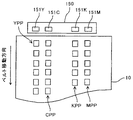
Y,C,M,Kパッチパターン像は、図9に示されるように、中間転写ベルト10上で重なり合わないように、ベルト幅方向に並んでいる。具体的には、Yパッチパターン像YPPは、中間転写ベルト10の幅方向における一端部に転写される。また、Cパッチパターン像CPPは、ベルト幅方向において、Yパッチパターン像よりも少し中央側にずれた位置に転写される。また、Mパッチパターン像MPPは、中間転写ベルト10の幅方向における他端部に転写される。また、Kパッチパターン像KPPは、ベルト幅方向において、Kパッチパターン像よりも少し中央側にずれた位置に転写される。
As shown in FIG. 9, the Y, C, M, and K patch pattern images are arranged in the belt width direction so as not to overlap on the
光学センサーユニット150は、互いにベルト幅方向の異なる位置でベルトの光反射特性を検知するY用の反射型フォトセンサー151Yを有している。また、C用の反射型フォトセンサー151C、K用の反射型フォトセンサー151K、M用の反射型フォトセンサー151Mも有している。
The
Y用の反射型フォトセンサー151Yは、中間転写ベルト10の幅方向の一端部に形成されたYパッチパターン像YPPのYパッチ状トナー像のYトナー付着量を検知する位置に配設されている。また、第C用の反射型フォトセンサー151Cは、ベルト幅方向において、Yパッチパターン像YPPの近くに位置するCパッチパターン像CPPのCパッチ状トナー像のCトナー付着量を検知する位置に配設されている。また、M反射型フォトセンサー151Mは、中間転写ベルト10の幅方向の他端部に形成されたMパッチパターン像MPPのMパッチ状トナー像のMトナー付着量を検知する位置に配設されている。また、K用の反射型フォトセンサー150cは、ベルト幅方向において、Mパッチパターン像MPPの近くに位置するKパッチパターン像KPPのKパッチ状トナー像のKトナー付着量を検知する位置に配設されている。
The Y
制御部110は、光学センサーユニット150の4つの反射型フォトセンサーから順次送られてくる出力信号に基づいて、各色のパッチ状トナー像の光反射率を演算し、演算結果に基づいてトナー付着量を求めてRAMに格納していく。なお、中間転写ベルト10の走行に伴って光学センサーユニット150との対向位置を通過した各色のパッチパターン像は、図示しないクリーニング装置によってベルトおもて面からクリーニングされる。
The control unit 110 calculates the light reflectance of each color patch-like toner image based on output signals sequentially sent from the four reflective photosensors of the
制御部110は、次に、RAMに格納したトナー付着量と、それとは別にRAMに格納した各パッチトナー像における露光部電位(潜像電位)のデータと現像バイアスVbのデータとに基づいて、直線近似式(Y=a×Vp+b)を算出する。具体的には、図10に示されるように、y軸をトナー付着量とし、且つx軸を現像ポテンシャルとする2次元座標における両者の関係を示す近似直線式である。そして、近似直線式に基づいて、目標のトナー付着量を実現する現像ポテンシャルVpを求め、その現像ポテンシャルVpを実現する現像バイアスVbである現像バイアス基準値および帯電バイアス基準値、(およびLDパワー)を求める。それらの結果については、不揮発メモリーに記憶する。このような現像バイアス基準値、並びに帯電バイアス基準値(及びLDパワー)の算出及び記憶を、Y,C,M,Kの各色についてそれぞれ行ってプロセスコントロール処理を終了する。その後、プリントジョブにおいては、Y,C,M,Kについてそれぞれ、不揮発性メモリーに記憶している現像バイアス基準値に基づいた値の現像バイアスVbを、現像電源11Y,11C,11M,11Kから出力させる。また、不揮発性メモリーに記憶している帯電バイアス基準値に基づいた値の帯電バイアスVdを、帯電電源12Y,12C,12M,12Kから出力させたり、LDパワーをレーザー書込装置21から出力させたりする。
Next, the control unit 110, based on the toner adhesion amount stored in the RAM, the exposure portion potential (latent image potential) data and the development bias Vb data in each patch toner image stored in the RAM separately. A linear approximation formula (Y = a × Vp + b) is calculated. Specifically, as shown in FIG. 10, an approximate linear expression showing the relationship between two points in two-dimensional coordinates with the y-axis as the toner adhesion amount and the x-axis as the development potential. Then, a developing potential Vp that achieves a target toner adhesion amount is obtained based on the approximate linear equation, and a developing bias reference value and a charging bias reference value that are developing bias Vb that realizes the developing potential Vp (and LD power). Ask for. These results are stored in nonvolatile memory. Such development bias reference value and charging bias reference value (and LD power) are calculated and stored for each of Y, C, M, and K colors, and the process control process is terminated. Thereafter, in the print job, for each of Y, C, M, and K, the development bias Vb having a value based on the development bias reference value stored in the nonvolatile memory is output from the development power supplies 11Y, 11C, 11M, and 11K. Let Further, the charging bias Vd having a value based on the charging bias reference value stored in the nonvolatile memory is output from the charging
このようなプロセスコントロール処理を実施して目標のトナー付着量を実現する現像バイアス基準値、帯電バイアス基準値(及びLDパワー)を決定することで、Y,C,M,Kの各色についてそれぞれ、画像全体の画像濃度を長期間に渡って安定化させることができる。しかしながら、感光体20Y,20C,20M,20Kと、現像スリーブ81Y,81C,81M,81Kとの間の現像ギャップの変動(以下、ギャップ変動という)に起因する頁内での周期的な画像濃度ムラを引き起こしてしまう。
By determining the development bias reference value and the charging bias reference value (and LD power) for realizing the target toner adhesion amount by performing such process control processing, for each of Y, C, M, and K colors, The image density of the entire image can be stabilized over a long period of time. However, periodic image density unevenness in the page due to the development gap fluctuation (hereinafter referred to as gap fluctuation) between the
この画像濃度ムラは、感光体20Y,20C,20M,20Kの回転周期で発生するものと、現像スリーブ81Y,81C,81M,81Kの回転周期で発生するものとが重畳されたものになる。具体的には、感光体20Y,20C,20M,20Kの回転軸が偏心していると、それに起因して、感光体一周あたりでサインカーブ状の変動曲線となるギャップ変動が生ずる。これにより、感光体20Y,20C,20M,20Kと、現像スリーブ81Y,81C,81M,81Kとの間に形成される現像電界にも、感光体一周あたりでサインカーブ状の変動曲線となる電界強度変動が生ずる。そして、この電界強度変動により、感光体一周あたりでサインカーブ状の変動曲線となる画像濃度ムラが発生する。また、感光体表面の外形には、少なからず歪みがある。この歪みに応じた感光体一周あたりで同じパターンとなる特性の周期的なギャップ変動に起因する画像濃度ムラも発生する。更には、現像スリーブ81Y,81C,81M,81Kの偏心や外形歪みによるスリーブ回転周期のギャップ変動に起因する周期的な画像濃度ムラも発生する。特に、感光体20Y,20C,20M,20Kよりも小径な現像スリーブ81Y,81C,81M,81Kの偏心や外形歪みによる画像濃度ムラは比較的短い周期で発生することから、目立ってしまう。
This image density unevenness is a superimposition of what occurs at the rotation cycle of the photoconductors 20Y, 20C, 20M and 20K and that which occurs at the rotation cycle of the developing sleeves 81Y, 81C, 81M and 81K. Specifically, if the rotation axes of the photoconductors 20Y, 20C, 20M, and 20K are decentered, a gap fluctuation that becomes a sine curve-like fluctuation curve occurs around the photoconductor. As a result, the electric field strength that forms a sine-curve variation curve around the photosensitive member also in the developing electric field formed between the
そこで、制御部110は、プリントジョブ時において、Y,C,M,Kの各色についてそれぞれ、以下のような出力変化処理を実施する。即ち、制御部110は、Y,C,M,Kの各色についてそれぞれ、感光体回転周期で発生する画像濃度ムラを相殺することが可能な現像電界強度変動を生じせしめるための現像バイアスの出力パターンデータを不揮発性メモリーに記憶している。また、現像スリーブ回転周期で発生する画像濃度ムラを相殺することが可能な現像電界強度変動を生じせしめるための現像バイアスの出力パターンデータも不揮発性メモリーに記憶している。 Therefore, the control unit 110 performs the following output change process for each of the colors Y, C, M, and K during a print job. That is, the control unit 110 outputs a development bias output pattern for causing fluctuations in the development electric field intensity that can cancel out image density unevenness that occurs in the photosensitive member rotation period for each of Y, C, M, and K colors. Data is stored in non-volatile memory. Further, development bias output pattern data for causing fluctuations in the development electric field intensity that can cancel out image density unevenness that occurs in the development sleeve rotation cycle is also stored in the nonvolatile memory.
感光体20Y,20C,20M,20K用の現像バイアスの出力パターンデータは、感光体一周期分の出力パターンであって、且つ感光体20Y,20C,20M,20Kの基準姿勢タイミングを基準にしたパターンを表している。それぞれの出力パターンデータは、基準値決定処理としてのプロセスコントロール処理で決定されたY,C,M,K用の現像バイアス基準値を基準にして現像電源(11Y,11C,11M,11K)からの現像バイアスの出力を変化させるためのものである。例えば、データテーブル方式のパターンデータである場合には、基準姿勢タイミングから一周期分の期間内において、所定の時間間隔毎の現像バイアス出力差分を示すデータ群を格納したものになっている。そのデータ群の先頭のデータが基準姿勢タイミングにおける現像バイアス出力差分を示しており、二番目、三番目、四番目・・・のデータが以降における所定の時間間隔毎の現像バイアス出力差分を示している。0、−5、−7、−9・・・というデータ群からなる出力パターンは、基準姿勢タイミングから所定の時間間隔毎の現像バイアス出力差分を0[V]、−5[V]、−7[V]、−9[V]・・・にすることを表している。感光体回転周期で発生する画像濃度ムラを抑えるだけであれば、それらの値を現像バイアス基準値に重畳した値の現像バイアスを現像電源から出力させればよい。但し、本複写機では、現像スリーブ回転周期で発生する画像濃度ムラも抑えるので、感光体回転周期の画像濃度ムラを抑えるための現像バイアス出力差分と、現像スリーブ回転周期の画像濃度ムラを抑えるための現像バイアス出力差分とを重畳するようになっている。
The development bias output pattern data for the
現像スリーブ81Y,81C,81M,81K用の現像バイアスの出力パターンデータは、現像スリーブ一周期分の出力パターンであって、且つ現像スリーブ81Y,81C,81M,81Kの基準姿勢タイミングを基準にしたパターンを表している。それぞれの出力パターンデータは、基準値決定処理としてのプロセスコントロール処理で決定されたY,C,M,K用の現像バイアス基準値を基準にして現像電源(11Y,11C,11M,11K)からの現像バイアスの出力を変化させるためのものである。データテーブル方式のパターンデータの場合には、そのデータ群の先頭のデータが基準姿勢タイミングにおける現像バイアス出力差分を示しており、二番目、三番目、四番目・・・のデータが以降における所定の時間間隔毎の現像バイアス出力差分を示している。その時間間隔は、感光体20Y,20C,20M,20K用の出力パターンデータのデータ群が反映している時間間隔と同じになっている。
The development bias output pattern data for the development sleeves 81Y, 81C, 81M, 81K is an output pattern for one cycle of the development sleeve, and a pattern based on the reference posture timing of the development sleeves 81Y, 81C, 81M, 81K. Represents. Each output pattern data is supplied from the development power supply (11Y, 11C, 11M, 11K) based on the development bias reference values for Y, C, M, K determined in the process control process as the reference value determination process. This is for changing the output of the developing bias. In the case of data table type pattern data, the first data of the data group indicates the development bias output difference at the reference posture timing, and the second, third, fourth,. The development bias output difference for each time interval is shown. The time interval is the same as the time interval reflected by the output pattern data group for the
制御部110は、作像処理のときには、感光体20Y,20C,20M,20K用の出力パターンデータからのデータの読み込みを所定の時間間隔毎で行う。同時に、現像スリーブ81Y,81C,81M,81K用の出力パターンデータからのデータの読み込みも同じ時間間隔毎で行う。それぞれの読み込みについては、データ群の最後まで読み込んでも基準姿勢タイミングが到来しない場合には、到来するまで読み込み値を最後のデータと同じ値にする。また、データ群の最後まで読み込む前に基準姿勢タイミングが到来した場合には、データの読み込み位置を最初のデータに戻す。なお、感光体用の出力パターンデータからのデータ読み込みについては、感光体回転センサー(76Y,76C,76M,76K)から基準姿勢タイミング信号が送られてきたタイミングを基準姿勢タイミングとする。また、現像スリーブ用の出力パターンデータからのデータ読み込みについては、スリーブ回転センサー(83Y,83C,83M,83K)から基準姿勢タイミング信号が送られてきたタイミングを基準姿勢タイミングとする。
The controller 110 reads data from the output pattern data for the
Y,C,M,Kについてそれぞれ、このようなデータの読み込みを行う過程で、感光体用の出力パターンデータから読み込んだデータと、現像スリーブ用の出力パターンデータから読み込んだデータとを加算して重畳値を求める。例えば、感光体用の出力パターンデータから読み込んだデータが−5[V]であり、現像スリーブ用の出力パターンデータから読み込んだデータが2[V]であった場合には、−5[V]と2[V]とを加算して重畳値を−3[V]として求める。そして、例えば現像バイアス基準値が−550[V]である場合には、重畳値の加算によって求められる−553[V]を現像電源から出力させる。このような処理を、Y,C,M,Kについてそれぞれ、所定の時間間隔毎に行う。 In the process of reading such data for each of Y, C, M, and K, the data read from the output pattern data for the photosensitive member and the data read from the output pattern data for the developing sleeve are added. Find the superimposed value. For example, when the data read from the output pattern data for the photosensitive member is −5 [V] and the data read from the output pattern data for the developing sleeve is 2 [V], −5 [V] And 2 [V] are added to obtain a superimposition value as -3 [V]. For example, when the development bias reference value is −550 [V], −553 [V] obtained by adding the superimposed value is output from the development power supply. Such processing is performed for each of Y, C, M, and K at predetermined time intervals.
これにより、感光体20Y,20C,20M,20Kと、現像スリーブ81Y,81C,81M,81Kとの間の現像電界に、次の2つの電界強度変動を重畳した電界強度変動を相殺し得る電界強度変動を発生させる。即ち、感光体20Y,20C,20M,20Kの偏心や外形歪みによる感光体回転周期で発生するギャップ変動に起因する電界強度変動、及び現像スリーブ81Y,81C,81M,81Kの偏心や外形歪みによるスリーブ回転周期で発生する電界強度変動である。このようにすることで、感光体20Y,20C,20M,20Kや、現像スリーブ81Y,81C,81M,81Kの回転姿勢にかかわらず、ほぼ一定の現像電界を感光体と現像スリーブとの間に形成する。これにより、感光体回転周期で発生する画像濃度ムラと、スリーブ回転周期で発生する画像濃度ムラとの両方を抑えることができる。
As a result, the electric field strength that can cancel out the electric field strength fluctuation obtained by superimposing the following two electric field strength fluctuations on the developing electric field between the
感光体20Y,20C,20M,20K用の現像バイアスの出力パターンデータや、現像スリーブ81Y,81C,81M,81K用の現像バイアスの出力パターンデータについては、構築処理を所定のタイミングで実施することによって構築する。この所定のタイミングは、工場出荷後の初めのプリントジョブに先立つタイミング(以下、初期起動タイミングという)、及び作像ユニット18Y,18C,18M,18Kの交換を検知したタイミング(以下、交換検知タイミングという)である。初期起動タイミングでは、Y,C,M,Kの全色についてそれぞれ、感光体用の現像バイアスの出力パターンデータを構築する(以下、感光体周期出力パターンデータという)。また、現像スリーブ用の現像バイアスの出力パターンデータ(以下、スリーブ周期出力パターンデータという)も構築する。これに対し、交換検知タイミングでは、交換が検知された作像ユニットについてだけ、感光体周期出力パターンデータとスリーブ周期出力パターンデータとを構築する。このような構築が可能になるように、図6に示されるように、作像ユニット18Y,18C,18M,18Kの交換をそれぞれ個別に検知するためのユニット着脱センサー17Y,17C,17M,17Kが設けられている。
For the development bias output pattern data for the
初期起動タイミングにおける構築処理では、まず、Yベタトナー像からなるY濃度ムラ検知用トナー像を感光体20Y上に作像する。また、Cベタトナー像,Mベタトナー像,Kベタトナー像からなるC濃度ムラ検知用トナー像,M濃度ムラ検知用トナー像,K濃度ムラ検知用トナー像を、感光体20C,感光体20M,感光体20K上に作像する。そして、それらの濃度ムラ検知用トナー像を、図11に示されるように、中間転写ベルト10に一次転写する。同図において、Y濃度ムラ検知用トナー像YITは、感光体20Yの回転周期で発生する画像濃度ムラを検知するためのものであるので、ベルト移動方向において、感光体20Yの周長よりも大きな長さで形成される。同様に、C濃度ムラ検知用トナトナー像CIT,M濃度ムラ検知用トナー像MIT,K濃度ムラ検知用トナー像KITも、ベルト移動方向の長さが感光体20C,20M,20Kの周長よりも大きくなっている。
In the construction process at the initial activation timing, first, a Y density unevenness detection toner image composed of a Y solid toner image is formed on the
なお、図11では、便宜上、4つの濃度ムラ検知用トナー像(YIT,CIT,MIT,KIT)をベルト幅方向に一直線上に並べて形成した例を示している。しかし、実際には、個々の濃度ムラ検知用トナー像のベルト上における形成位置は、ベルト移動方向において最大で感光体周長と同じ値ほどずれる場合がある。これは、例えば、各色についてそれぞれ、濃度ムラ検知用トナー像の先端位置と、感光体の周方向における基準位置(基準姿勢タイミングで現像領域に進入する感光体表面位置)とを一致させるように、濃度ムラ検知用トナー像の作像を開始するからである。つまり、各色の濃度ムラ検知用トナー像は、その先端を感光体の周方向における基準位置に一致させるように作像される。 For convenience, FIG. 11 shows an example in which four density unevenness detection toner images (YIT, CIT, MIT, KIT) are formed on a straight line in the belt width direction. However, in practice, the formation position of each density unevenness detection toner image on the belt may be shifted by the same value as the circumferential length of the photosensitive member at the maximum in the belt moving direction. For example, for each color, the leading end position of the density unevenness detection toner image and the reference position in the circumferential direction of the photosensitive member (the photosensitive member surface position that enters the developing region at the reference posture timing) are matched. This is because image formation of a density unevenness detection toner image is started. That is, the density unevenness detection toner images of the respective colors are formed so that the front ends thereof coincide with the reference positions in the circumferential direction of the photoreceptor.
また、制御部110は、構築処理をプロセスコントロール処理とセットで行うようになっている。具体的には、構築処理を実施する直前でプロセスコントロール処理を実施して各色についてそれぞれ現像バイアス基準値を決定しておく。そして、プロセスコントロール処理の直後に実施する構築処理において、各色についてそれぞれ、プロセスコントロール処理で決定しておいた現像バイアス基準値の条件で濃度ムラ検知用トナー像を現像する。このため、理論的には、濃度ムラ検知用トナー像は目標トナー付着量になるように作像されるが、実際にはギャップ変動によって微妙な濃度ムラが出現してしまう。 Further, the control unit 110 is configured to perform the construction process as a set with the process control process. Specifically, the process control process is performed immediately before the construction process is performed, and the development bias reference value is determined for each color. In the construction process performed immediately after the process control process, the density unevenness detection toner image is developed for each color under the condition of the development bias reference value determined in the process control process. Therefore, theoretically, the density unevenness detection toner image is formed so as to have the target toner adhesion amount, but in reality, subtle density unevenness appears due to gap fluctuation.
濃度ムラ検知用トナー像の作像を開始してから(静電潜像の書き込みを開始してから)、濃度検知用トナー像の先端を光学センサーユニット150の反射型フォトセンサーによる検知位置に進入させるまでのタイムラグは、各色毎に異なった値である。但し、同じ色であれば、経時的に一定の値である(以下、この値を書込−検知タイムラグという)。
After starting the image formation of the density unevenness detection toner image (after starting the writing of the electrostatic latent image), the front end of the density detection toner image enters the detection position of the
制御部110は、各色についてそれぞれ書込−検知タイムラグを不揮発性メモリーに予め記憶している。そして、各色についてそれぞれ、濃度ムラ検知用トナー像の作像を開始した後、書込−検知タイムラグが経過した時点から、反射型フォトセンサーからの出力のサンプリングを開始する。このサンプリングについては、感光体回転一周期に渡って、所定の時間間隔毎に繰り返し行う。その時間間隔は、出力変化処理において用いる出力パターンデータにおける個々のデータを読み込む時間間隔と同じ値である。制御部110は、各色についてそれぞれ、サンプリングデータに基づいて、トナー付着量(画像濃度)と時間(又は感光体表面位置)との関係を示す濃度ムラグラフを構築し、その濃度ムラグラフから、二つの濃度ムラパターンを抽出する。一つ目は、感光体回転周期で発生している濃度ムラパターンである。また、二つ目は、現像スリーブ回転周期で発生している濃度ムラパターンである。 The control unit 110 stores a write-detection time lag for each color in advance in a nonvolatile memory. Then, after the image formation of the density unevenness detection toner image is started for each color, sampling of the output from the reflective photosensor is started from the time when the writing-detection time lag has elapsed. This sampling is repeated at predetermined time intervals over one rotation of the photosensitive member. The time interval is the same value as the time interval for reading individual data in the output pattern data used in the output change process. The control unit 110 constructs a density unevenness graph indicating the relationship between the toner adhesion amount (image density) and time (or photoconductor surface position) for each color based on the sampling data, and based on the density unevenness graph, two densities are obtained. Extract unevenness pattern. The first is a density unevenness pattern generated at the photosensitive member rotation period. The second is a density unevenness pattern generated in the developing sleeve rotation cycle.
制御部110は、各色についてそれぞれ、上述したサンプリングデータに基づいて、感光体回転周期で発生している濃度ムラパターンを抽出すると、トナー付着量平均値(画像濃度平均値)を算出する。このトナー付着量平均値は、感光体回転一周期における現像ギャップの変動の平均値をほぼ反映した値になる。そこで、制御部110は、そのトナー付着量平均値を基準にして、感光体回転周期の濃度ムラパターンを相殺するための感光体周期出力パターンデータを構築する。具体的には、濃度パターンに含まれる複数のトナー付着量データにそれぞれ個別に対応するバイアス出力差分を算出する。そのバイアス出力差分は、トナー付着量平均値を基準にするものである。トナー付着量平均値と同じ値のトナー付着量データに対応するバイアス出力差分については、ゼロとして算出する。 The control unit 110 calculates a toner adhesion average value (image density average value) by extracting the density unevenness pattern generated in the photosensitive member rotation period based on the sampling data described above for each color. The average toner adhesion amount is a value that substantially reflects the average value of the change in the development gap during one rotation of the photoreceptor. Therefore, the control unit 110 constructs photoconductor cycle output pattern data for canceling out the density unevenness pattern of the photoconductor rotation cycle based on the average toner adhesion amount. Specifically, a bias output difference corresponding to each of a plurality of toner adhesion amount data included in the density pattern is calculated. The bias output difference is based on the toner adhesion amount average value. The bias output difference corresponding to the toner adhesion amount data having the same value as the toner adhesion amount average value is calculated as zero.
また、トナー付着量平均値よりも大きいトナー付着量データに対応するバイアス出力差分については、そのトナー付着量とトナー付着量平均値との差分に応じたプラス極性の値として算出する。プラス極性のバイアス出力差分であるので、マイナス極性の現像バイアスを現像バイアス基準値よりも低い値(絶対値の小さい値)に変化させるデータである。 The bias output difference corresponding to the toner adhesion amount data larger than the toner adhesion amount average value is calculated as a positive polarity value corresponding to the difference between the toner adhesion amount and the toner adhesion amount average value. Since this is a positive polarity bias output difference, it is data for changing the negative polarity development bias to a value lower than the development bias reference value (a value having a small absolute value).
また、トナー付着量平均値よりも小さいトナー付着量データに対応するバイアス出力差分については、そのトナー付着量とトナー付着量平均値との差分に応じたマイナス極性の値として算出する。マイナス極性のバイアス出力差分であるので、マイナス極性の現像バイアスを現像バイアス基準値よりも高い値(絶対値の大きい値)に変化させるデータである。 The bias output difference corresponding to the toner adhesion amount data smaller than the toner adhesion amount average value is calculated as a negative polarity value corresponding to the difference between the toner adhesion amount and the toner adhesion amount average value. Since this is a negative polarity bias output difference, it is data for changing the negative polarity development bias to a value higher than the development bias reference value (a value having a large absolute value).
このようにして、個々のトナー付着量データに対応するバイアス出力差分を求め、それらを順に並べたデータを出力パターンデータたる感光体周期出力パターンデータとして構築する。 In this way, a bias output difference corresponding to each toner adhesion amount data is obtained, and data obtained by arranging them in order is constructed as photoconductor cycle output pattern data as output pattern data.
また、制御部110は、各色についてそれぞれ、上述したサンプリングデータに基づいて、現像スリーブ回転周期で発生している濃度ムラパターンを抽出すると、トナー付着量平均値(画像濃度平均値)を算出する。このトナー付着量平均値は、現像スリーブ回転一周期における現像ギャップの変動の平均値をほぼ反映した値になる。そこで、制御部110は、そのトナー付着量平均値を基準にして、現像スリーブ回転周期の濃度ムラパターンを相殺するためのスリーブ周期出力パターンデータを構築する。その具体的なやり方については、感光体回転周期の濃度ムラパターンを相殺するための感光体周期出力パターンデータを構築する方法と同様である。 Further, when the density unevenness pattern generated in the developing sleeve rotation cycle is extracted for each color based on the above-described sampling data, the control unit 110 calculates a toner adhesion amount average value (image density average value). The average toner adhesion amount is a value that substantially reflects the average value of the change in the development gap in one rotation period of the development sleeve. Therefore, the control unit 110 constructs sleeve cycle output pattern data for canceling out the density unevenness pattern of the developing sleeve rotation cycle with reference to the average toner adhesion amount. The specific method is the same as the method of constructing photoconductor cycle output pattern data for canceling out the density unevenness pattern of the photoconductor rotation cycle.
以上のように、各色についてそれぞれ、構築処理において構築した感光体周期出力パターンデータ、及びスリーブ周期出力パターンデータを用いて、出力変化処理において現像バイアスVbの現像電源(11Y,11C,11M,11K)から出力を変化させる。これにより、感光体回転周期で発生する画像濃度ムラや、現像スリーブ回転周期で発生する画像濃度ムラの発生を抑えることができる。 As described above, the development power source (11Y, 11C, 11M, 11K) of the development bias Vb in the output change process using the photosensitive member periodic output pattern data and the sleeve periodic output pattern data constructed in the construction process for each color. Change the output from. As a result, it is possible to suppress the occurrence of image density unevenness that occurs in the photosensitive member rotation period and image density unevenness that occurs in the developing sleeve rotation period.
ところが、現像電源11Y,11C,11M,11Kの出力上限や出力下限に起因して、周期的な画像濃度ムラの発生を有効に抑えることができなくなるおそれがあった。例えば、現像バイアス基準値=−800[V]を基準にすると仮定する。そして、現像バイアスVbの出力値を、感光体回転周期の画像濃度ムラを相殺するための感光体周期出力パターンデータと、現像スリーブ回転周期の画像濃度ムラを相殺するためのスリーブ周期出力パターンデータとに従って、次のように変化させるとする。即ち、例えば、−800[V]を基準にして、−785[V]〜−815[V]の範囲で変化させるとする。しかし、現像電源11Y,11C,11M,11Kの出力上限が例えば−800[V]であると、本来であれば、現像バイアスVbを、−800[V]よりも高い値に変化させたいタイミングであるにもかかわらず、上限の−800[V]を出力せざるを得ない。そのタイミングでは、画像濃度ムラの発生を抑えることができなくなってしまう。 However, due to the output upper limit and output lower limit of the development power supplies 11Y, 11C, 11M, and 11K, there is a possibility that the occurrence of periodic image density unevenness cannot be effectively suppressed. For example, it is assumed that the developing bias reference value = −800 [V] is used as a reference. Then, the output value of the developing bias Vb is a photosensitive member cycle output pattern data for canceling out image density unevenness in the photosensitive member rotation cycle, and sleeve cycle output pattern data for canceling out image density unevenness in the developing sleeve rotation cycle. And change as follows. That is, for example, it is assumed that the change is made in the range of -785 [V] to -815 [V] with -800 [V] as a reference. However, if the upper limit of the output of the development power supplies 11Y, 11C, 11M, and 11K is, for example, −800 [V], the development bias Vb is supposed to be changed to a value higher than −800 [V]. Despite being, the upper limit of −800 [V] must be output. At that timing, the occurrence of image density unevenness cannot be suppressed.
現像バイアスVbを出力上限よりも高い値に変化させたい場合だけでなく、現像バイアスVbを出力下限よりも低い値に変化させたい場合にも、同様にして、所定のタイミングにおいて画像濃度ムラの発生を抑えることができなくなってしまう。 Similarly, not only when the development bias Vb is to be changed to a value higher than the output upper limit, but also when the development bias Vb is desired to be changed to a value lower than the output lower limit, image density unevenness is similarly generated at a predetermined timing. It becomes impossible to suppress.
図12は、現像バイアスVbについての感光体周期出力パターン、スリーブ周期出力パターン、及び重畳出力パターンと、時間との関係の一例を示すグラフである。同図において、感光体周期出力パターンは、感光体周期出力パターンデータに従った現像バイアスVbの出力パターンを表している。また、スリーブ周期出力パターンは、スリーブ周期出力パターンデータに従った現像バイアスVbの出力パターンを表している。また、重畳出力パターンは、前述した二つの出力パターンを重畳した現像バイアスの出力パターンを表している。また、現像バイアス出力パターンは、現像電源から実際に出力される現像バイアスVbの変動パターンを表している。 FIG. 12 is a graph showing an example of the relationship between the photosensitive member cycle output pattern, the sleeve cycle output pattern, the superimposed output pattern, and the time for the developing bias Vb. In the figure, a photoconductor cycle output pattern represents an output pattern of the developing bias Vb according to photoconductor cycle output pattern data. The sleeve cycle output pattern represents the output pattern of the developing bias Vb according to the sleeve cycle output pattern data. The superimposed output pattern represents a development bias output pattern obtained by superimposing the two output patterns described above. The development bias output pattern represents a variation pattern of the development bias Vb actually output from the development power source.
図示のように、本来であれば、現像バイアス出力パターンを重畳出力パターンと同じパターンにしたいにもかかわらず、重畳出力パターンにおける−800[V]よりも高い値を全て−800[V]に置き換えたパターンにしている。−800[V]よりも高い値を−800[V]に置き換えているときには、画像濃度ムラの発生を抑えることができなくなっている。 As shown in the drawing, all values higher than −800 [V] in the superimposed output pattern are replaced with −800 [V] even though the development bias output pattern is supposed to be the same pattern as the superimposed output pattern. It has a pattern. When a value higher than −800 [V] is replaced with −800 [V], occurrence of uneven image density cannot be suppressed.
現像バイアス基準値は、環境変動に大きな影響を受ける。低温低湿環境では、現像装置内のトナーが摩擦帯電し易くなってトナーの帯電量Q/Mが比較的高い値になる。そして、現像剤中において、磁性キャリア粒子に対するトナー粒子の静電付着力が比較的強くなることから、現像性能が低下する。このような状態で基準値補正処理たるプロセスコントロール処理を実施すると、低下した現像性能で所望のトナー付着量を得るために、現像バイアス基準値が比較的高い値に設定される。これにより、重畳出力パターンの波形の一部が現像電源の出力上限を超えてしまうことがあることを、本発明者らは実験によって見出している。 The development bias reference value is greatly affected by environmental fluctuations. In a low-temperature and low-humidity environment, the toner in the developing device is easily triboelectrically charged, and the toner charge amount Q / M becomes a relatively high value. In the developer, the electrostatic adhesion force of the toner particles to the magnetic carrier particles becomes relatively strong, so that the development performance is deteriorated. When the process control process as the reference value correction process is performed in such a state, the development bias reference value is set to a relatively high value in order to obtain a desired toner adhesion amount with a reduced development performance. As a result, the present inventors have found through experiments that a part of the waveform of the superimposed output pattern may exceed the output upper limit of the developing power supply.
次に、本複写機の特徴的な構成について説明する。
制御部110は、Y,C,M,Kの各色についてそれぞれ、重畳出力パターン(出力範囲)の適否を判定する判定処理と、必要に応じて重畳出力パターンの位置を高電位側又は低電位側にシフトさせるシフト用データ処理とを実施するようになっている。
Next, a characteristic configuration of the copying machine will be described.
The control unit 110 determines the suitability of the superimposed output pattern (output range) for each of the colors Y, C, M, and K, and sets the position of the superimposed output pattern on the high potential side or the low potential side as necessary. And shift data processing for shifting to.
図13は、制御部110によって実施される判定・シフト処理における処理フローを示すフローチャートである。この判定・シフト処理は、判定処理とシフト用データ処理とを合わせて行うものであり、プロセスコントロール処理によってY,C,M,K用の現像バイアス基準値がそれぞれ決定された直後に必ず実施されるものである。制御部110は、判定・シフト処理を開始すると、各色についてそれぞれ図示の処理フローを実施する。 FIG. 13 is a flowchart illustrating a processing flow in the determination / shift processing performed by the control unit 110. This determination / shift processing is performed in combination with the determination processing and the shift data processing, and is always performed immediately after the development bias reference values for Y, C, M, and K are determined by the process control processing. Is. When the determination / shift process is started, the control unit 110 executes the illustrated process flow for each color.
具体的には、まず、不揮発性メモリーに記憶している感光体周期出力パターンの最大値及び最小値を特定した後(ステップ1:以下、ステップをSと記す)、スリーブ周期出力パターンの最大値及び最小値を特定する(S2)。感光体回転周期とスリーブ回転周期とは互いに異なり、且つ前者の方が後者よりも長い。このため、感光体周期出力パターンに対しては、複数周回分のスリーブ周期出力パターンを重畳することになる。そして、一周期分の感光体周期出力パターンに対して、どのような位相でスリーブ周期出力パターンの群を重畳するのかは、感光体の周期毎に異なってくる。感光体を複数周回に渡って回転させていく過程で、感光体周期出力パターンの最大値に対し、スリーブ周期出力パターンの最大値を重畳することもある。また、感光体周期出力パターンの最小値に対し、スリーブ周期出力パターンの最小値を重畳することもある。このため、2つの周期出力パターンを重畳した重畳出力パターンの最大値は、感光体周期出力パターンの最大値と、スリーブ周期出力パターンの最大値とを合算した値になる。また、重畳出力パターンの最小値は、感光体周期出力パターンの最小値と、スリーブ周期出力パターンの最小値とを合算した値になる。 Specifically, first, the maximum value and the minimum value of the photosensitive member cycle output pattern stored in the nonvolatile memory are specified (step 1: hereinafter, step is denoted as S), and then the maximum value of the sleeve cycle output pattern. And the minimum value is specified (S2). The photosensitive member rotation period and the sleeve rotation period are different from each other, and the former is longer than the latter. For this reason, a sleeve cycle output pattern for a plurality of turns is superimposed on the photoconductor cycle output pattern. The phase at which the group of sleeve cycle output patterns is superimposed on the photoconductor cycle output pattern for one cycle differs for each cycle of the photoconductor. In the process of rotating the photoconductor over a plurality of turns, the maximum value of the sleeve cycle output pattern may be superimposed on the maximum value of the photoconductor cycle output pattern. Further, the minimum value of the sleeve cycle output pattern may be superimposed on the minimum value of the photoconductor cycle output pattern. For this reason, the maximum value of the superimposed output pattern obtained by superimposing the two periodic output patterns is the sum of the maximum value of the photosensitive member periodic output pattern and the maximum value of the sleeve periodic output pattern. Further, the minimum value of the superimposed output pattern is a value obtained by adding the minimum value of the photosensitive member cycle output pattern and the minimum value of the sleeve cycle output pattern.
そこで、制御部110は、重畳出力パターンの最大値である重畳最大値を、感光体周期出力パターンデータの最大値と、スリーブ周期出力パターンデータの最大値との合算によって求める(S3)。そして、その重畳最大値を現像バイアス基準値に加算して現像バイアス出力最大値を求める(S4)。また、重畳出力パターンの最小値である重畳最小値を、感光体周期出力パターンデータの最小値と、スリーブ周期出力パターンデータの最小値との合算によって求める(S5)。そして、その重畳最小値を現像バイアス基準値に加算して現像バイアス出力最小値を求める(S6)。次に、現像バイアス出力最大値について、現像電源の出力上限を超えるか否かを判定する(S7)。そして、超える場合には(S7でY)、両者の差分を算出した後(S8)、現像バイアス基準値をその差分と同じ分だけ低い値に補正してから(S9)、一連の処理フローを終了する。この補正により、画像全体の画像濃度は目標よりも低くなるものの、現像バイアス出力最大値は現像電源の出力上限と同じ値になるので、重畳出力パターンを正しいパターンで生起させることが可能になる。よって、頁内での画像濃度ムラの発生を確実に抑えることができるようになる。 Therefore, the control unit 110 obtains the maximum superimposed value, which is the maximum value of the superimposed output pattern, by adding the maximum value of the photosensitive member cycle output pattern data and the maximum value of the sleeve cycle output pattern data (S3). Then, the superposition maximum value is added to the development bias reference value to obtain the development bias output maximum value (S4). Further, the minimum superimposed value, which is the minimum value of the superimposed output pattern, is obtained by adding the minimum value of the photosensitive member cycle output pattern data and the minimum value of the sleeve cycle output pattern data (S5). Then, the minimum superimposed bias value is added to the development bias reference value to obtain the minimum development bias output value (S6). Next, it is determined whether or not the development bias output maximum value exceeds the output upper limit of the development power supply (S7). If the difference is exceeded (Y in S7), the difference between the two is calculated (S8), the development bias reference value is corrected to a value lower by the same amount as the difference (S9), and a series of processing flow is performed. finish. By this correction, although the image density of the entire image becomes lower than the target, the maximum value of the development bias output becomes the same value as the output upper limit of the development power supply, so that the superimposed output pattern can be generated in a correct pattern. Therefore, it is possible to reliably suppress the occurrence of image density unevenness in the page.
一方、上記S7の工程において、現像バイアス出力最大値について現像電源の出力上限を超えない場合には(S7でN)、次に、現像バイアス出力最小値について現像電源の出力下限を下回るか否かを判定する(S10)。そして、下回る場合には(S10でY)、両者の差分を算出した後(S11)、現像バイアス基準値をその差分と同じ分だけ高い値に補正してから(S12)、一連の処理フローを終了する。この補正により、画像全体の画像濃度は目標よりも高くなるものの、現像バイアス出力最小値は現像電源の出力下限と同じ値になるので、重畳出力パターンを正しいパターンで生起させることが可能になる。よって、頁内での画像濃度ムラの発生を確実に抑えることができるようになる。このとき、帯電バイアスVdおよびLDパワーは、所定の画像濃度を保つように適宜適切な値に設定される。 On the other hand, in step S7, if the development bias output maximum value does not exceed the output upper limit of the development power supply (N in S7), then whether or not the development bias output minimum value falls below the development power supply output lower limit. Is determined (S10). If the difference is smaller (Y in S10), the difference between the two is calculated (S11), the development bias reference value is corrected to a value that is higher by the difference (S12), and a series of processing flows is performed. finish. By this correction, although the image density of the entire image becomes higher than the target, the minimum value of the development bias output becomes the same value as the output lower limit of the development power supply, so that the superimposed output pattern can be generated in a correct pattern. Therefore, it is possible to reliably suppress the occurrence of image density unevenness in the page. At this time, the charging bias Vd and the LD power are appropriately set to appropriate values so as to maintain a predetermined image density.
上記S10の工程において、現像バイアス出力最小値が出力下限を下回らなかった場合には(S10でN)、そのまま一連の処理フローを終了する。 If the minimum developing bias output value does not fall below the output lower limit in the step S10 (N in S10), the series of processing flow ends.
制御部110は、以上のような判定・シフト処理を、Y,C,M,Kの各色毎にそれぞれ個別に行う。これにより、現像バイアス基準値と重畳出力パターンとに従った現像バイアス出力パターンの出力最大値が現像電源の出力上限を超える場合には、超えさせない値に現像バイアス基準値を補正する。また、現像バイアス出力パターンの出力最小値が現像電源の出力下限を下回る場合には、下回らせない値に現像バイアス基準値を補正する。それらの補正により、出力上限や出力下限にかかわらず、重畳出力パターンと同じパターンの現像バイアス出力パターンで現像バイアスVbを変化させて、頁内の画像濃度ムラの発生を抑えることができる。 The control unit 110 individually performs the determination / shift processing as described above for each color of Y, C, M, and K. As a result, when the output maximum value of the development bias output pattern according to the development bias reference value and the superimposed output pattern exceeds the output upper limit of the development power supply, the development bias reference value is corrected to a value that is not exceeded. Further, when the minimum output value of the development bias output pattern is below the output lower limit of the development power supply, the development bias reference value is corrected to a value that cannot be lowered. With these corrections, regardless of the output upper limit or the output lower limit, it is possible to change the development bias Vb with the same development bias output pattern as the superimposed output pattern, thereby suppressing the occurrence of uneven image density in the page.
現像バイアス基準値を基準にして現像バイアスVbの出力値を重畳出力パターンに従って変化させる構成について説明したが、次のように変化させるようにしてもよい。即ち、重畳出力パターンではなく、感光体周期出力パターン、又はスリーブ周期出力パターンの何れかに従って現像バイアスVbの出力値を変化させる構成である。この構成の場合、感光体周期出力パターンを構築するために必要な感光体回転センサー(76Y〜K)と、スリーブ周期出力パターンを構築するために必要なスリーブ回転センサー(83Y〜K)とのうち、何れか一方だけを設ければよい。 Although the configuration in which the output value of the development bias Vb is changed according to the superimposed output pattern based on the development bias reference value has been described, it may be changed as follows. That is, the output value of the developing bias Vb is changed according to either the photosensitive member periodic output pattern or the sleeve periodic output pattern, not the superimposed output pattern. In the case of this configuration, among the photoconductor rotation sensors (76Y to 76K) necessary for constructing the photoconductor cycle output pattern and the sleeve rotation sensors (83Y to K) necessary for constructing the sleeve cycle output pattern. Only one of them may be provided.
また、初期起動タイミングで実施する構築処理について説明したが、作像ユニットの交換を検知した直後に実施する構築処理では、交換を検知した色についてだけ、構築処理を実施するようになっている。 Further, the construction process performed at the initial activation timing has been described. However, in the construction process performed immediately after the replacement of the image forming unit is detected, the construction process is performed only for the color in which the replacement is detected.
なお、プロセスコントロール処理については、初期起動タイミングや交換検知タイミングの他にも、所定時間経過毎や所定枚数プリント毎などの定期的なタイミングで実施するようになっている。そして、定期的なタイミングで実施するプロセスコントロールの後には、必ず判定・シフト処理を実施する。 Note that the process control processing is performed at regular timings such as every elapse of a predetermined time or every printing of a predetermined number of sheets, in addition to the initial activation timing and replacement detection timing. Then, after process control performed at regular timing, determination / shift processing is always performed.
次に、実施形態に係る複写機の一部の構成を他の構成に変形した変形形態に係る複写機について説明する。なお、以下に特筆しない限り、変形形態に係る複写機の構成は、実施形態と同様である。
ベタ部と中間調部とが混在する画像において、ベタ部の画像濃度は現像バイアスVbと静電潜像の電位である潜像電位Vlとの差である現像ポテンシャルに大きな影響を受ける。これに対し、中間調部の画像濃度は現像ポテンシャルよりも、感光体の地肌部電位Vdと現像バイアスVbとの差である地肌ポテンシャルに大きな影響を受けることがある。これは次に説明する理由による。即ち、ベタ部では、全てのドットが隣接するドットに周縁部を重ね合わせている。つまり、孤立ドットが存在しない。これに対し、中間調部では、孤立ドットが存在していたり、少数のドットの集合からなる少数ドット群が存在していたりする。それら孤立ドットや少数ドット群は、ベタ部よりもエッジ効果の影響を大きく受けることにより、ベタ部と同じ地肌ポテンシャルの条件下では、ベタ部よりも中間調部の方が感光体上の付着力が強く、ギャップ変動の影響を受けにくい。さらに、ベタ部よりも単位面積あたりのトナー付着量が多くなっており、ベタ時のトナー付着量変動量と比較すると、中間調部でのギャップ変動によるトナー付着量変動量は小さくなる。これにより、実施形態に係る複写機のように、ベタトナー像からなる濃度ムラ検知用トナー像に基づいて構築した重畳出力パターンで現像バイアスVbを変化させると、ベタ部については画像濃度ムラを抑えることができる代わりに、中間調部では過補正になる。そして、その過補正により、画像濃度ムラを中間調部に発生させてしまう。
Next, a description will be given of a copier according to a modified embodiment in which a part of the configuration of the copier according to the embodiment is modified to another configuration. Unless otherwise specified below, the configuration of the copying machine according to the modified embodiment is the same as that of the embodiment.
In an image in which a solid portion and a halftone portion are mixed, the image density of the solid portion is greatly influenced by the development potential that is the difference between the development bias Vb and the latent image potential Vl that is the potential of the electrostatic latent image. On the other hand, the image density of the halftone portion may be more greatly influenced by the background potential, which is the difference between the background potential Vd of the photoreceptor and the development bias Vb, than the development potential. This is for the reason explained below. That is, in the solid portion, all the dots are overlapped with the peripheral edge on the adjacent dots. That is, there are no isolated dots. On the other hand, in the halftone portion, there are isolated dots, or there are a small number of dots composed of a small number of dots. These isolated dots and minority dot groups are more affected by the edge effect than the solid part, so that under the same background potential as the solid part, the halftone part adheres more to the photoconductor than the solid part. Is strong and less susceptible to gap fluctuations. Further, the toner adhesion amount per unit area is larger than that of the solid portion, and the toner adhesion amount fluctuation amount due to the gap fluctuation in the halftone portion is smaller than the toner adhesion amount fluctuation amount of the solid portion. As a result, when the developing bias Vb is changed with the superimposed output pattern constructed based on the density unevenness detection toner image composed of the solid toner image as in the copying machine according to the embodiment, the image density unevenness is suppressed for the solid portion. Instead, it is overcorrected in the halftone part. The overcorrection causes image density unevenness to occur in the halftone portion.
エッジ効果は、地肌ポテンシャルの影響を大きく受けることから、地肌ポテンシャルを調整することで、前述の過補正を修正することが可能である。地肌ポテンシャルを変化させるには、帯電バイアスの変化によって地肌部電位Vdを変化させればよい。このように地肌部電位Vdを変化させても、現像ポテンシャルについては、概ね一定に維持することが可能である。例えば、通常の地肌部電位Vd=−1100[V]、現像バイアスVb=−700[V]、潜像電位Vl=−50[V]という条件で、必要に応じて地肌部電位Vdを−1000[V]や、−1200[V]に変化させたとする。このように変化させても、潜像書込強度を、−50[V]程度の飽和露光電位が得られる値に設定していれば、地肌部電位Vdにかかわらず、潜像電位Vlを概ね−50[V]に維持することが可能である。このため、地肌部電位Vdの変化によって地肌ポテンシャルを変化させても、現像ポテンシャルVbについては一定に維持することが可能なので、ベタ部の画像濃度に影響を与えることはない。 Since the edge effect is greatly influenced by the background potential, the above-described overcorrection can be corrected by adjusting the background potential. In order to change the background potential, the background portion potential Vd may be changed by changing the charging bias. As described above, even when the background portion potential Vd is changed, the development potential can be maintained substantially constant. For example, the background potential Vd is set to −1000 as necessary under the conditions of normal background potential Vd = −1100 [V], development bias Vb = −700 [V], and latent image potential Vl = −50 [V]. It is assumed that the voltage is changed to [V] or -1200 [V]. If the latent image writing intensity is set to a value at which a saturated exposure potential of about −50 [V] can be obtained even if it is changed in this way, the latent image potential Vl is approximately set regardless of the background portion potential Vd. It can be maintained at −50 [V]. For this reason, even if the background potential is changed by changing the background portion potential Vd, the development potential Vb can be kept constant, so that the image density of the solid portion is not affected.
図14は、変形形態に係る複写機において、初期起動タイミングで実施される処理の処理フローを示すフローチャートである。この処理において、制御部110は、まず、プロセスコントロール処理を実施する(S1)。そして、上述した構築処理としての第一構築処理を実施して、画像のベタ部の画像濃度ムラを抑えるための現像バイアス用の感光体周期出力パターンデータやスリーブ周期出力パターンデータを構築する(S2)。このとき、各色の濃度ムラ検知用トナー像については、それぞれ、直前のプロセスコントロール処理で決定した現像バイアス基準値と同じ値の現像バイアスVbの条件で作像する。次に、構築した感光体周期出力パターンデータの最大値、最小値、スリーブ周期出力パターンデータの最大値、最小値に基づいて、現像バイアス基準値の適否を判定したり、現像バイアス基準値を補正したりするための判定・シフト処理を実施する(S3)。このとき、中間調の濃度を保つために現像バイアスと同じだけ帯電バイアスもシフトさせる。 FIG. 14 is a flowchart showing a processing flow of processing performed at the initial activation timing in the copying machine according to the modified embodiment. In this process, the control unit 110 first performs a process control process (S1). Then, the first construction process as the construction process described above is performed to construct the photosensitive body cycle output pattern data and the sleeve cycle output pattern data for developing bias for suppressing the image density unevenness of the solid portion of the image (S2). ). At this time, the density unevenness detection toner images of the respective colors are formed under the conditions of the development bias Vb having the same value as the development bias reference value determined in the immediately preceding process control process. Next, the suitability of the development bias reference value is determined and the development bias reference value is corrected based on the maximum and minimum values of the constructed photosensitive member periodic output pattern data and the maximum and minimum values of the sleeve periodic output pattern data. A determination / shift process is performed to perform (S3). At this time, the charging bias is shifted by the same amount as the developing bias in order to maintain a halftone density.
その後、第二構築処理(S4)を実施して、画像の中間調部の画像濃度ムラを抑えるための帯電バイアス用の感光体周期出力パターンデータやスリーブ周期出力パターンデータを構築する。 Thereafter, a second construction process (S4) is performed to construct photosensitive body periodic output pattern data and sleeve periodic output pattern data for charging bias for suppressing image density unevenness in the halftone portion of the image.
第二構築処理(S4)の具体的な処理内容は次の通りである。
まず、Y中間調トナー像からなるY濃度ムラ検知用トナー像を感光体20Y上に作像する。また、C中間調トナー像,M中間調トナー像,K中間調トナー像からなるC濃度ムラ検知用トナー像,M濃度ムラ検知用トナー像,K濃度ムラ検知用トナー像を、感光体20C,感光体20M,感光体20K上に作像する。この作像の際、Y,C,M,K用の現像バイアスVbを、それぞれに対応する現像バイアス基準値、感光体周期出力パターン、感光体基準姿勢タイミング、スリーブ周期出力パターン、及びスリーブ基準姿勢タイミングに基づいて変化させる。この条件では、感光体回転周期やスリーブ回転周期の画像濃度ムラはベタ部において発生しなくなるが、前述した4つの濃度ムラ検知用トナー像は中間調トナー像からなるので、現像バイアスVbの過補正によって画像濃度ムラが発生する。制御部110は、その画像濃度ムラを検知するべく、光学センサーユニット150の4つの反射型フォトセンサーからの出力のサンプリングを所定の時間間隔で感光体一周期以上の時間において行う。
The specific processing content of the second construction processing (S4) is as follows.
First, a Y density unevenness detection toner image composed of a Y halftone toner image is formed on the
その後、制御部110は、各色についてそれぞれ得たサンプリングデータに基づいて、感光体回転周期で発生している濃度ムラパターンを抽出する。そして、その変動波形の積分によってトナー付着量平均値(画像濃度平均値)を算出した後、そのトナー付着量平均値を基準にして、感光体回転周期の濃度ムラパターンを相殺するための帯電バイアスの感光体周期出力パターンデータを構築する。具体的には、濃度パターンに含まれる複数のトナー付着量データにそれぞれ個別に対応するバイアス出力差分を算出する。そのバイアス出力差分は、トナー付着量平均値を基準にするものである。トナー付着量平均値と同じ値のトナー付着量データに対応するバイアス出力差分については、ゼロとして算出する。また、トナー付着量平均値よりも大きいトナー付着量データに対応するバイアス出力差分については、そのトナー付着量とトナー付着量平均値との差分に応じたプラス極性の値として算出する。プラス極性のバイアス出力差分であるので、マイナス極性の現像バイアスを現像バイアス基準値よりも低い値(絶対値の小さい値)に変化させるデータである。また、トナー付着量平均値よりも小さいトナー付着量データに対応するバイアス出力差分については、そのトナー付着量とトナー付着量平均値との差分に応じたマイナス極性の値として算出する。マイナス極性のバイアス出力差分であるので、マイナス極性の現像バイアスを現像バイアス基準値よりも高い値(絶対値の大きい値)に変化させるデータである。 Thereafter, the control unit 110 extracts the density unevenness pattern generated in the photosensitive member rotation cycle based on the sampling data obtained for each color. Then, after calculating the toner adhesion amount average value (image density average value) by integration of the fluctuation waveform, the charging bias for canceling the density unevenness pattern of the photosensitive member rotation period on the basis of the toner adhesion amount average value. The photosensitive member periodic output pattern data is constructed. Specifically, a bias output difference corresponding to each of a plurality of toner adhesion amount data included in the density pattern is calculated. The bias output difference is based on the toner adhesion amount average value. The bias output difference corresponding to the toner adhesion amount data having the same value as the toner adhesion amount average value is calculated as zero. The bias output difference corresponding to the toner adhesion amount data larger than the toner adhesion amount average value is calculated as a positive polarity value corresponding to the difference between the toner adhesion amount and the toner adhesion amount average value. Since this is a positive polarity bias output difference, it is data for changing the negative polarity development bias to a value lower than the development bias reference value (a value having a small absolute value). The bias output difference corresponding to the toner adhesion amount data smaller than the toner adhesion amount average value is calculated as a negative polarity value corresponding to the difference between the toner adhesion amount and the toner adhesion amount average value. Since this is a negative polarity bias output difference, it is data for changing the negative polarity development bias to a value higher than the development bias reference value (a value having a large absolute value).
このようにして、個々のトナー付着量データに対応するバイアス出力差分を求め、それらを順に並べたデータを帯電バイアス用の感光体周期出力パターンデータとして構築する。 In this way, a bias output difference corresponding to each toner adhesion amount data is obtained, and data obtained by arranging them in order is constructed as photosensitive member periodic output pattern data for charging bias.
次に、制御部110は、各色についてそれぞれ、上述したサンプリングデータに基づいて、現像スリーブ回転周期で発生している濃度ムラパターンを抽出した後、トナー付着量平均値(画像濃度平均値)を算出する。そして、そのトナー付着量平均値を基準にして、現像スリーブ回転周期の濃度ムラパターンを相殺するための帯電バイアス用のスリーブ周期出力パターンデータを構築する。その具体的なやり方については、感光体回転周期の濃度ムラパターンを相殺するための感光体周期出力パターンデータを構築する方法と同様である。 Next, the control unit 110 calculates a toner adhesion amount average value (image density average value) after extracting a density unevenness pattern generated in the developing sleeve rotation period based on the sampling data described above for each color. To do. Then, with reference to the average value of the toner adhesion amount, sleeve period output pattern data for charging bias for canceling the density unevenness pattern of the developing sleeve rotation period is constructed. The specific method is the same as the method of constructing photoconductor cycle output pattern data for canceling out the density unevenness pattern of the photoconductor rotation cycle.
以上のようにして、帯電バイアス用の感光体周期出力パターンデータやスリーブ周期出力パターンデータを構築したら、それらに含まれる個々のデータの順番をそれぞれ所定の番号分だけずらす。具体的には、感光体周期出力パターンデータにおける先頭データは、感光体の周面における全域のうち、感光体が基準の回転姿勢になったときに現像領域に進入する箇所に対応するものである。その箇所は、現像領域で帯電せしめられるのではなく、帯電ローラ(71Y,C,M,K)と感光体(20Y,C,M,K)との当接領域で帯電せしめられる。当接領域から現像領域に移動するまでにはタイムラグがあることから、そのタイムラグに相当する番号分だけ個々のデータの位置をずらすのである。例えば、250のデータからなるパターンデータである場合に、1番目から230番目までのデータの位置をそれぞれ20番ずつ後にずらすとともに、231番目から250番目までのデータを1番目から20番目のデータにする。スリーブ周期出力パターンデータも同様にして、各種のデータの位置を所定の番号分だけずらす。 As described above, when the photosensitive member periodic output pattern data and the sleeve periodic output pattern data for the charging bias are constructed, the order of the individual data included therein is shifted by a predetermined number. Specifically, the head data in the photosensitive member periodic output pattern data corresponds to a portion that enters the developing region when the photosensitive member assumes the reference rotation posture in the entire area on the peripheral surface of the photosensitive member. . The portion is not charged in the development area, but is charged in the contact area between the charging roller (71Y, C, M, K) and the photoconductor (20Y, C, M, K). Since there is a time lag before moving from the contact area to the development area, the position of each data is shifted by the number corresponding to the time lag. For example, in the case of pattern data composed of 250 data, the positions of the 1st to 230th data are shifted by 20th respectively, and the 231st to 250th data are changed to the 1st to 20th data. To do. Similarly, the sleeve period output pattern data is shifted by a predetermined number in the position of various data.
ユーザーの命令に基づく画像を形成する際には、各色についてそれぞれ、第一構築処理で構築した現像バイアス用の感光体周期出力パターンデータやスリーブ周期出力パターンデータに基づいて、現像電源からの現像バイアスVbの出力を変化させる。具体的には、感光体周期出力パターンデータと、感光体基準姿勢タイミングと、スリーブ周期出力パターンデータと、スリーブ基準姿勢タイミングとに基づいて重畳出力パターンデータを構築する。そして、その重畳出力パターンデータと現像バイアス基準値とに基づいて、現像バイアスVbの出力値を変化させる。これにより、感光体回転周期やスリーブ回転周期で発生するベタ部の画像濃度ムラを抑えることができる。 When forming an image based on the user's command, the development bias from the development power source is generated for each color based on the photosensitive body cycle output pattern data for the development bias and the sleeve cycle output pattern data constructed in the first construction process. Vb output is changed. Specifically, the superimposed output pattern data is constructed based on the photosensitive member cycle output pattern data, the photosensitive member reference posture timing, the sleeve cycle output pattern data, and the sleeve reference posture timing. Then, the output value of the developing bias Vb is changed based on the superimposed output pattern data and the developing bias reference value. As a result, it is possible to suppress unevenness in the image density of the solid portion that occurs in the photosensitive member rotation cycle or the sleeve rotation cycle.
また、ユーザーの命令に基づく画像を形成する際には、各色についてそれぞれ、第二構築処理で構築した帯電バイアス用の感光体周期出力パターンデータやスリーブ周期出力パターンデータに基づいて、帯電電源からの帯電バイアスの出力を変化させる。具体的には、感光体周期出力パターンデータと、感光体基準姿勢タイミングと、スリーブ周期出力パターンデータと、スリーブ基準姿勢タイミングとに基づいて重畳出力パターンデータを構築する。そして、その重畳出力パターンデータと、プロセスコントロール処理で決定しておいた基準値たる帯電バイアス基準値とに基づいて、帯電電源からの帯電バイアスの出力を変化させる。これにより、現像バイアスVbの過補正に起因して、感光体回転周期やスリーブ回転周期で発生する中間調部の画像濃度ムラを抑えることができる。 Further, when forming an image based on a user's command, for each color, from the charging power source based on the charging bias photosensitive member cycle output pattern data and sleeve cycle output pattern data constructed in the second construction process, respectively. Change the output of the charging bias. Specifically, the superimposed output pattern data is constructed based on the photosensitive member cycle output pattern data, the photosensitive member reference posture timing, the sleeve cycle output pattern data, and the sleeve reference posture timing. Then, the output of the charging bias from the charging power source is changed based on the superimposed output pattern data and the charging bias reference value that is the reference value determined in the process control process. Accordingly, it is possible to suppress the image density unevenness of the halftone portion that occurs in the photosensitive member rotation cycle or the sleeve rotation cycle due to the overcorrection of the developing bias Vb.
なお、ユーザーの命令に基づく画像を形成する際の現像バイアス基準値については、補正しないでプロセスコントロール処理で決定した値のまま用いてもよい。つまり、第二構築処理で使用する現像バイアス基準値だけを、判定・補正処理によって補正するようにしてもよい。 Note that the development bias reference value for forming an image based on a user command may be used as it is without being corrected and determined in the process control process. That is, only the development bias reference value used in the second construction process may be corrected by the determination / correction process.
次に、変形形態に係る複写機の一部の構成を他の構成に変形した各変形例に係る複写機について説明する。なお、以下に特筆しない限り、各変形例に係る複写機の構成は、変形形態と同様である。
[第一変形例]
第一変形例に係る複写機においては、上述した判定・シフト処理を実施しない。その代わりに、所定の条件が具備されたことに基づいて、次のような補正処理を行う。即ち、基準値決定処理たるプロセスコントロール処理で現像バイアス基準値を決定する際に参照する目標トナー付着量、又はプロセスコントロール処理で決定した現像バイアス基準値、帯電バイアス基準値、及びLDパワーを補正する補正処理である。
Next, a description will be given of a copying machine according to each modified example in which a part of the configuration of the copying machine according to the modified embodiment is modified to another configuration. Unless otherwise specified, the configuration of the copying machine according to each modification is the same as that of the modification.
[First modification]
In the copying machine according to the first modification, the above-described determination / shift processing is not performed. Instead, the following correction processing is performed based on the fact that the predetermined condition is satisfied. That is, the target toner adhesion amount that is referred to when the development bias reference value is determined in the process control process that is the reference value determination process, or the development bias reference value, the charging bias reference value, and the LD power that are determined in the process control process are corrected. It is a correction process.
所定の条件としては、例えば、環境が低温低湿になるという条件、環境が高温高湿になるという条件、及びプロセスコントロールで算出した現像バイアス基準値又は帯電バイアス基準値が所定の範囲になるという3つを採用している。環境が低温低湿になった場合、トナー帯電量Q/Mが比較的高い値になって現像能力が低くなることから、プロセスコントロール処理で決定される現像バイアス基準値や帯電バイアス基準値が比較的高い値になる。これにより、現像バイアスVbの出力範囲における一部が現像電源の上限を超え易くなる。また、帯電バイアスVdの出力範囲における一部が帯電電源の上限を超え易くなる。そこで、制御部110は、環境の低温低湿化が図示しない環境センサーによって検知された場合には、プロセスコントロール処理で参照する目標トナー付着量を例えば標準の0.40[mg/cm2]から0.35[mg/cm2]に補正する。この補正により、現像バイアス基準値や帯電バイアス基準値をより低い値に決定することで、現像バイアスVbの出力範囲を現像電源の出力上限よりも低くすることが可能になる。また、帯電バイアスVdの出力範囲を帯電電源の出力上限よりも低くすることも可能になる。更には、第二構築処理で現像バイアスVbを確実に出力パターンデータに従って変化させることができるようになる。 The predetermined conditions include, for example, a condition that the environment becomes low temperature and low humidity, a condition that the environment becomes high temperature and high humidity, and that the development bias reference value or charging bias reference value calculated by the process control falls within a predetermined range. One is adopted. When the environment becomes low temperature and low humidity, the toner charge amount Q / M becomes a relatively high value and the developing ability becomes low. Therefore, the developing bias reference value and the charging bias reference value determined by the process control process are relatively low. High value. Thereby, a part of the output range of the developing bias Vb easily exceeds the upper limit of the developing power source. Also, a part of the output range of the charging bias Vd tends to exceed the upper limit of the charging power source. Therefore, when the low temperature and low humidity of the environment is detected by an environmental sensor (not shown), the control unit 110 changes the target toner adhesion amount referred to in the process control process from 0, for example, from the standard 0.40 [mg / cm 2 ] to 0. Correct to 35 [mg / cm 2 ]. By this correction, the development bias reference value and the charging bias reference value are determined to be lower values, so that the output range of the development bias Vb can be made lower than the output upper limit of the development power supply. In addition, the output range of the charging bias Vd can be made lower than the output upper limit of the charging power source. Furthermore, the development bias Vb can be reliably changed according to the output pattern data in the second construction process.
また、環境の高温高湿化が図示しない環境センサーによって検知された場合には、プロセスコントロール処理で参照する目標トナー付着量を例えば標準の0.40[mg/cm2]から0.45[mg/cm2]に補正する。この補正により、現像バイアス基準値や帯電バイアスをより高い値に決定することで、現像バイアスの出力範囲を現像電源の出力下限よりも高くすることが可能になる。また、帯電バイアスの出力範囲を帯電電源の出力下限よりも高くすることが可能になる。なお、目標トナー付着量を補正する代わりに、現像バイアス基準値や帯電バイアス基準値を補正してもよい。 Further, when high temperature and high humidity of the environment is detected by an environmental sensor (not shown), the target toner adhesion amount referred to in the process control process is set to, for example, the standard 0.40 [mg / cm 2 ] to 0.45 [mg / Cm 2 ]. By determining the development bias reference value and the charging bias to a higher value by this correction, the output range of the development bias can be made higher than the output lower limit of the development power supply. In addition, the output range of the charging bias can be made higher than the output lower limit of the charging power source. Instead of correcting the target toner adhesion amount, the developing bias reference value or the charging bias reference value may be corrected.
プロセスコントロール処理で算出した現像バイアス基準値が所定の範囲になると、出力パターンデータに従った現像バイアスVbの変化範囲の一部が、現像電源の出力上限を超えたり、出力下限を下回ったりし易くなる。例えば、現像バイアス基準値が現像電源の出力上限との差を20[V]以下にする値になると、出力パターンデータに従った現像バイアスVbの変化範囲の一部が、現像電源の出力上限を超え易くなる。また、現像バイアス基準値が現像電源の出力下限との差を20[V]以下にする値になると、出力パターンデータに従った現像バイアスVbの変化範囲の一部が、現像電源の出力下限を下回り易くなる。帯電バイアス基準値も同様に、所定の範囲になると、出力パターンデータに従った帯電バイアスVdの変化範囲の一部が、帯電電源の出力上限を超えたり、出力下限を下回ったりし易くなる。 When the development bias reference value calculated by the process control process falls within a predetermined range, a part of the change range of the development bias Vb according to the output pattern data is likely to exceed the output upper limit of the development power source or fall below the output lower limit. Become. For example, when the development bias reference value becomes a value that makes the difference from the output upper limit of the developing power source 20 [V] or less, a part of the change range of the developing bias Vb according to the output pattern data becomes the output upper limit of the developing power source. It becomes easy to exceed. When the difference between the development bias reference value and the output lower limit of the development power supply is 20 [V] or less, a part of the change range of the development bias Vb according to the output pattern data becomes lower than the output lower limit of the development power supply. It becomes easy to fall below. Similarly, when the charging bias reference value falls within a predetermined range, a part of the changing range of the charging bias Vd according to the output pattern data easily exceeds the output upper limit of the charging power source or falls below the output lower limit.
そこで、プロセスコントロール処理で算出した現像バイアス基準値が所定の範囲(高い値の範囲)になった場合には、目標トナー付着量を例えば標準の0.40[mg/cm2]から0.35[mg/cm2]に補正して、現像バイアス基準値の決定をやり直す。この補正により、現像バイアス基準値をより低い値に決定することで、現像バイアスVbの出力範囲を現像電源の出力上限よりも低くすることが可能になる。また、プロセスコントロール処理で算出した帯電バイアス基準値が所定の範囲(高い値の範囲)になった場合にも、目標トナー付着量を例えば標準の0.40[mg/cm2]から0.35[mg/cm2]に補正して、現像バイアス基準値の決定をやり直す。この補正により、帯電バイアス基準値をより低い値に決定することで、帯電バイアスVdの出力範囲を帯電電源の出力上限よりも低くすることが可能になる。 Therefore, when the development bias reference value calculated by the process control process falls within a predetermined range (high value range), the target toner adhesion amount is set to, for example, the standard 0.40 [mg / cm 2 ] to 0.35. Correct to [mg / cm 2 ] and redetermine the development bias reference value. By determining the developing bias reference value to a lower value by this correction, it becomes possible to make the output range of the developing bias Vb lower than the output upper limit of the developing power source. Further, even when the charging bias reference value calculated by the process control processing falls within a predetermined range (high value range), the target toner adhesion amount is set to, for example, the standard 0.40 [mg / cm 2 ] to 0.35. Correct to [mg / cm 2 ] and redetermine the development bias reference value. By determining the charging bias reference value to a lower value by this correction, the output range of the charging bias Vd can be made lower than the output upper limit of the charging power source.
また、プロセスコントロール処理で算出した現像バイアス基準値が所定の範囲(低い値の範囲)になった場合には、目標トナー付着量を例えば標準の0.40[mg/cm2]から0.45[mg/cm2]に補正して、現像バイアス基準値の決定をやり直す。この補正により、現像バイアス基準値をより高いい値に決定することで、現像バイアスVbの出力範囲を現像電源の出力下限よりも高くすることが可能になる。また、プロセスコントロール処理で算出した帯電バイアス基準値が所定の範囲(高い値の範囲)になった場合にも、目標トナー付着量を例えば標準の0.40[mg/cm2]から0.40[mg/cm2]に補正して、現像バイアス基準値の決定をやり直す。この補正により、帯電バイアス基準値をより高い値に決定することで、帯電バイアスVdの出力範囲を帯電電源の出力下限よりも高くすることが可能になる。 When the development bias reference value calculated by the process control process falls within a predetermined range (low value range), the target toner adhesion amount is changed from, for example, the standard 0.40 [mg / cm 2 ] to 0.45. Correct to [mg / cm 2 ] and redetermine the development bias reference value. By determining the development bias reference value to a higher value by this correction, the output range of the development bias Vb can be made higher than the output lower limit of the development power supply. Further, even when the charging bias reference value calculated by the process control processing falls within a predetermined range (high value range), the target toner adhesion amount is changed from, for example, the standard 0.40 [mg / cm 2 ] to 0.40. Correct to [mg / cm 2 ] and redetermine the development bias reference value. By determining the charging bias reference value to a higher value by this correction, the output range of the charging bias Vd can be made higher than the output lower limit of the charging power source.
現像バイアス基準値または帯電バイアス基準値の決定のやり直しのときには、現像能力(現像γ)と目標トナー付着量との関係から演算によってそれら基準値を求めればよい。直前のプロセスコントロール処理で得られた図10の特性図に基づいて、新たな目標トナー付着量が得られる現像ポテンシャルVpを求めるのである。このときのLDパワーについては予め設計されたテーブルや式などに沿って適宜設定すればよい。また、前述のような算術だけによって新たな基準値を求めるのではなく、プロセスコントロール処理を始めからやり直しても良い。また、所定の範囲として20[V]を例にして説明したが、この値に限られるものではない。 When redoing the determination of the development bias reference value or the charging bias reference value, these reference values may be obtained by calculation from the relationship between the developing ability (development γ) and the target toner adhesion amount. Based on the characteristic diagram of FIG. 10 obtained in the immediately preceding process control process, the development potential Vp for obtaining a new target toner adhesion amount is obtained. The LD power at this time may be set as appropriate according to a pre-designed table or expression. Further, instead of obtaining a new reference value only by the arithmetic as described above, the process control process may be performed again from the beginning. Moreover, although 20 [V] was demonstrated to the example as a predetermined range, it is not restricted to this value.
以上のように、バイアス出力範囲を電源の出力上下限範囲とした状態にて、前述の構築処理や印刷を実施する。 As described above, the above-described construction process and printing are performed in a state where the bias output range is set to the power output upper and lower limit range.
[第二変形例]
第二変形例に係る複写機においても、上述した判定・シフト処理を実施しない。その代わりに、プロセスコントロール処理において、現像バイアス基準値を所定の下限(以下、現像基準値下限)から上限(以下、現像基準値上限)までの範囲の値に決定する。目標トナー付着量を得るためには現像バイアス基準値を現像基準値上限よりも高い値にする必要がある場合であっても、現像バイアス基準値を現像基準値上限よりも高くせず、現像基準値上限と同じ値にする。また、目標トナー付着量を得るためには現像バイアス基準値を現像基準値下限よりも低い値にする必要がある場合であっても、現像バイアス基準値を現像基準値下限よりも低くせず、現像基準値下限と同じ値にする。
[Second modification]
Also in the copying machine according to the second modification, the above-described determination / shift processing is not performed. Instead, in the process control process, the development bias reference value is determined to be a value in a range from a predetermined lower limit (hereinafter referred to as development reference value lower limit) to an upper limit (hereinafter referred to as development reference value upper limit). Even if the development bias reference value needs to be higher than the upper limit of the development reference value to obtain the target toner adhesion amount, the development bias reference value is not set higher than the upper limit of the development reference value. Set to the same value as the upper limit. Further, in order to obtain the target toner adhesion amount, even when the development bias reference value needs to be lower than the development reference value lower limit, the development bias reference value is not made lower than the development reference value lower limit. Set to the same value as the lower limit of development reference value.
現像基準値上限については、予めの実験によって測定しておいた現像バイアスVbの出力パターンの振幅と、現像電源の出力上限とに基づいて、現像バイアス基準値を現像基準値上限にした場合であっても出力範囲を出力上限以下にする値に設定している。また、現像基準値下限については、現像バイアスVbの出力パターンの振幅と、現像電源の出力下限とに基づいて、現像バイアス基準値を現像基準値下限にした場合であっても出力範囲を出力下限以上にする値に設定している。このため、出力パターンデータに従って現像電源から出力される現像バイアスVbの変化範囲の最大値を確実に現像電源の出力上限以下にし、且つ同変化範囲の最小値を確実に現像電源の出力下限以上にすることが可能になる。これにより、帯電電源の出力上限や出力下限にかかわらず、現像バイアスVbを確実に出力パターンデータに従ったパターンで変化させて、頁内の画像濃度ムラを確実に抑えることができる。 The upper limit of the development reference value is a case where the development bias reference value is set to the upper limit of the development reference value based on the amplitude of the output pattern of the development bias Vb measured by a previous experiment and the output upper limit of the development power source. However, the output range is set to a value that is less than the output upper limit. As for the development reference value lower limit, the output range is set to the output lower limit even when the development bias reference value is set to the development reference value lower limit based on the amplitude of the output pattern of the development bias Vb and the output lower limit of the development power supply. It is set to the above value. For this reason, the maximum value of the change range of the development bias Vb output from the development power supply according to the output pattern data is surely made lower than the output upper limit of the development power supply, and the minimum value of the change range is made surely higher than the output lower limit of the development power supply. It becomes possible to do. Thereby, regardless of the output upper limit or output lower limit of the charging power source, the developing bias Vb can be reliably changed in a pattern according to the output pattern data, and image density unevenness in the page can be reliably suppressed.
また、第二変形例に係る複写機は、プロセスコントロール処理において、帯電バイアス基準値を所定の下限(以下、帯電基準値下限)から上限(以下、帯電基準値上限)までの範囲の値に決定する。目標トナー付着量を得るためには帯電バイアス基準値を帯電基準値上限よりも高い値にする必要がある場合であっても、帯電バイアス基準値を帯電基準値上限よりも高くせず、帯電基準値上限と同じ値にする。また、目標トナー付着量を得るためには帯電バイアス基準値を帯電基準値下限よりも低い値にする必要がある場合であっても、帯電バイアス基準値を帯電基準値下限よりも低くせず、帯電基準値下限と同じ値にする。 In the copying machine according to the second modification, the charging bias reference value is determined to be a value in a range from a predetermined lower limit (hereinafter referred to as charging reference value lower limit) to an upper limit (hereinafter referred to as charging reference value upper limit) in the process control process. To do. Even if it is necessary to set the charging bias reference value higher than the charging reference value upper limit in order to obtain the target toner adhesion amount, the charging bias reference value is not set higher than the charging reference value upper limit. Set to the same value as the upper limit. Further, even when the charging bias reference value needs to be lower than the charging reference value lower limit to obtain the target toner adhesion amount, the charging bias reference value is not made lower than the charging reference value lower limit. Set to the same value as the lower limit of the charging reference value.
帯電基準値上限については、予めの実験によって測定しておいた帯電バイアスVdの出力パターンの振幅と、帯電電源の出力上限とに基づいて、帯電バイアス基準値を帯電基準値上限にした場合であっても出力範囲を出力上限以下にする値に設定している。また、帯電基準値下限については、帯電バイアスVdの出力パターンの振幅と、帯電電源の出力下限とに基づいて、帯電バイアス基準値を帯電基準値下限にした場合であっても出力範囲を出力下限以上にする値に設定している。このため、出力パターンデータに従って帯電電源から出力される帯電バイアスVdの変化範囲の最大値を確実に帯電電源の出力上限以下にし、且つ同変化範囲の最小値を確実に帯電電源の出力下限以上にすることが可能になる。これにより、帯電電源の出力上限や出力下限にかかわらず、帯電バイアスVdを確実に出力パターンデータに従ったパターンで変化させて、頁内の画像濃度ムラを確実に抑えることができる。 The upper limit of the charging reference value is the case where the charging bias reference value is set to the upper limit of the charging reference value based on the amplitude of the output pattern of the charging bias Vd and the output upper limit of the charging power source, which are measured in advance by experiments. However, the output range is set to a value that is less than the output upper limit. In addition, regarding the charging reference value lower limit, the output range is set to the output lower limit even when the charging bias reference value is set to the charging reference value lower limit based on the amplitude of the output pattern of the charging bias Vd and the output lower limit of the charging power source. It is set to the above value. For this reason, the maximum value of the change range of the charging bias Vd output from the charging power supply according to the output pattern data is surely set to be equal to or lower than the output upper limit of the charging power supply, and the minimum value of the change range is reliably set to be higher than the output lower limit of the charging power supply. It becomes possible to do. Thus, regardless of the output upper limit or output lower limit of the charging power source, the charging bias Vd can be reliably changed in a pattern according to the output pattern data, and image density unevenness in the page can be reliably suppressed.
本発明の適用は、実施形態、変形形態、第一変形例、第二変形例に係る複写機に限定されるものではなく、種々の変形や変更が可能である。たとえば、本発明が適用可能な画像形成装置として、複写機の代わりに、プリンタ、ファクシミリ、複合機などを例示することが可能である。また、カラー画像を形成する画像形成装置ではなく、モノクロ画像しか形成することのできないモノクロ画像形成装置にも、本発明の適用が可能である。また、記録シートの片面だけに画像を形成する構成ではなく、必要に応じて両面に画像を形成する構成の画像形成装置にも、本発明の適用が可能である。記録シートとしては、普通紙、OHPシート、カード、ハガキ、厚紙、封筒などを例示することができる。 The application of the present invention is not limited to the copying machine according to the embodiment, the modification, the first modification, and the second modification, and various modifications and changes are possible. For example, as an image forming apparatus to which the present invention can be applied, a printer, a facsimile machine, a multifunction machine, or the like can be exemplified instead of a copying machine. The present invention can also be applied to a monochrome image forming apparatus that can form only a monochrome image, not an image forming apparatus that forms a color image. In addition, the present invention can be applied to an image forming apparatus configured to form an image on both sides as necessary, instead of forming an image on only one side of a recording sheet. Examples of the recording sheet include plain paper, OHP sheet, card, postcard, cardboard, envelope, and the like.
以上に説明したものは一例であり、本発明は、次の態様毎に特有の効果を奏する。
[態様A]
態様Aは、像担持体の移動する表面にトナー像を作像する作像手段(例えば作像ユニット18Y,C,M,K及びレーザー書込装置21の組み合わせ)と、前記像担持体上のトナー像を、直接あるいは中間転写体を介して記録シートに転写する転写手段(例えば転写ユニット)と、回転可能な回転体(例えば感光体20Y,C,M,Kや現像スリーブ81Y,C,M,K)と、前記回転体の回転姿勢を検知する回転姿勢検知手段(例えば感光体回転センサー76Y,C,M,Kやスリーブ回転センサー83Y,C,M,K)と、前記作像手段によって作像されたトナー像のトナー付着量を検知する付着量検知手段(例えば光学センサーユニット150)と、トナー像の作像から転写までの過程における所定のプロセスに寄与する電圧を出力する電源(例えば現像電源11Y,C,M,Kや帯電電源12Y,C,M,K)と、前記作像手段によって作像した濃度ムラ検知用トナー像のトナー付着量を前記付着量検知手段によって検知した結果、及び前記濃度ムラ検知用トナー像を作像する際の前記回転姿勢検知手段による検知結果に基づいて、前記電源から出力される電圧を変化させるための出力パターンデータを構築する構築処理、並びに、前記電源から出力される電圧を前記回転姿勢検知手段による検知結果及び前記出力パターンデータに基づいて変化させながら前記プロセスを実行する出力変化処理を実施する制御手段(例えば制御部110)とを備える画像形成装置において、前記出力変化処理にて前記電源から出力される前記電圧の出力範囲の適否を判定する判定処理と、前記判定処理にて不適切という判定結果になった場合に前記出力範囲をシフトさせるためのシフト用データ処理とを実施するように、前記制御手段を構成したことを特徴とするものである。
What has been described above is merely an example, and the present invention has a specific effect for each of the following modes.
[Aspect A]
In the aspect A, the image forming means (for example, a combination of the
かかる構成では、判定処理において、出力パターンデータに基づいて電源から出力される電圧の出力範囲の適否を判定する。例えば、判定基準として、出力範囲の最大値や最小値などを用い、最大値が電源の出力上限を超えたり、最小値が電源の出力下限を下回ったりした場合に、出力範囲について不適切であると判定する。そして、シフト用データ処理を実施して出力範囲をシフトさせる。具体的には、出力範囲の最大値が電源の出力上限を超える場合には、出力値をより小さな値にする側に出力範囲をシフトさせるためのデータ処理を行う。また、出力範囲の最小値が電源の出力下限を下回る場合には、出力値をより大きな値にする側に出力範囲をシフトさせるためのデータ処理を行う。何れの場合であっても、出力範囲をシフトさせると、現像ポテンシャルの平均値を変化させることになることから、画像全体の画像濃度を目標濃度からずらしてしまうが、電圧の出力については出力パターンに忠実に従った変化を生起させることが可能になる。これにより、電源の出力上限や出力下限にかかわらず、回転体の回転周期で発生する頁内の画像濃度ムラを確実に抑えることができる。 In such a configuration, in the determination process, the suitability of the output range of the voltage output from the power source is determined based on the output pattern data. For example, the maximum or minimum value of the output range is used as a criterion, and the output range is inappropriate when the maximum value exceeds the power output upper limit or the minimum value falls below the power output lower limit. Is determined. Then, shift data processing is performed to shift the output range. Specifically, when the maximum value of the output range exceeds the output upper limit of the power supply, data processing for shifting the output range to a smaller value is performed. Further, when the minimum value of the output range is below the output lower limit of the power source, data processing is performed to shift the output range to the side where the output value is set to a larger value. In any case, if the output range is shifted, the average value of the development potential is changed, so that the image density of the entire image is shifted from the target density. It is possible to cause changes that are faithfully followed. Thereby, regardless of the output upper limit or output lower limit of the power supply, it is possible to reliably suppress the image density unevenness in the page that occurs in the rotation cycle of the rotating body.
[態様B]
態様Bは、態様Aであって、前記作像手段が、前記像担持体たる潜像担持体(例えば感光体20Y,C,M,K)、前記潜像担持体を帯電せしめる帯電手段(例えば帯電装置70Y,C,M,K)、帯電後の前記潜像担持体に潜像を書き込む潜像書込手段(例えばレーザー書込装置21)、及び現像剤担持体に担持した現像剤を用いて前記潜像を現像する現像手段(例えば現像装置80Y,C,M,K)を有するものであり、且つ、前記電源が、前記帯電手段に供給する帯電バイアスを出力する帯電電源(例えば帯電電源12Y,C,M,K)、潜像書込強度を変化させるために前記潜像書込手段に搭載された内部電源回路、前記現像剤担持体に供給する現像バイアスを出力する現像電源(例えば現像電源11Y,C,M,K)、又は前記転写手段に供給する転写バイアスを出力する転写電源であることを特徴とするものである。かかる構成では、帯電電源、内部電源回路、現像電源、又は転写電源からの出力を変化させることで、回転体の回転周期で発生する画像濃度ムラを抑えることができる。
[Aspect B]
Aspect B is Aspect A, wherein the image forming means is a latent image carrier (eg, photoconductors 20Y, 20C, 20M, and 20K) that is the image carrier, and a charging means that charges the latent image carrier (eg, A charging
[態様C]
態様Cは、態様Bにおいて、前記作像手段によって互いに異なる作像条件で作像した複数のトナー付着量検知用トナー像のトナー付着量を前記付着量検知手段によって検知した結果、及びそれらトナー付着量検知用トナー像のそれぞれに個別に対応する作像条件に基づいて、前記帯電バイアス、前記内部電源回路からの出力、前記現像バイアス、又は前記転写バイアスの基準値を決定する基準値決定処理を所定のタイミングで実施するように、前記制御手段を構成したことを特徴とするものである。かかる構成では、基準値決定処理を定期的に実施することで、画像全体の画像濃度を長期間に渡って安定させることができる。
[Aspect C]
Aspect C is the result of detecting the toner adhesion amounts of a plurality of toner adhesion amount detection toner images formed by the imaging means under different imaging conditions in the aspect B, and the toner adhesion results thereof. A reference value determining process for determining a reference value for the charging bias, the output from the internal power supply circuit, the developing bias, or the transfer bias based on an image forming condition individually corresponding to each of the toner images for amount detection. The control means is configured to execute at a predetermined timing. In such a configuration, the image density of the entire image can be stabilized over a long period of time by periodically performing the reference value determination process.
[態様D]
態様Dは、態様Cにおいて、前記出力変化処理にて、前記基準値と前記出力パターンデータとに基づいて前記帯電電源、前記内部電源回路、前記現像電源、又は前記転写電源から出力される電圧を変化させ、前記判定処理にて、前記基準値と前記出力パターンデータとに基づいて前記出力範囲の適否を判定し、且つ前記シフト用データ処理にて、前記基準値の補正によって前記出力範囲をシフトさせるように、前記制御手段を構成したことを特徴とするものである。かかる構成では、基準値を補正するという簡単な処理により、出力変化処理によって出力される電圧の出力範囲を容易にシフトさせることができる。
[Aspect D]
Aspect D is a voltage output from the charging power supply, the internal power supply circuit, the developing power supply, or the transfer power supply based on the reference value and the output pattern data in the output change process in the aspect C. The determination process determines whether the output range is appropriate based on the reference value and the output pattern data, and the shift data process shifts the output range by correcting the reference value. As described above, the control means is configured. In such a configuration, the output range of the voltage output by the output change process can be easily shifted by a simple process of correcting the reference value.
[態様E]
態様Eは、態様C又はDにおいて、前記構築処理にて、前記内部電源回路からの出力、及び前記現像電源からの出力のそれぞれを一定にした条件で前記濃度ムラ検知用トナー像として全ベタトナー像からなるものを作像し、前記出力パターンデータとして、画像のベタ部における画像濃度の安定化を図るために前記内部電源回路及び前記現像電源における一方からの出力を変化させるためのベタ濃度安定化用出力パターンデータを前記全ベタトナー像のトナー付着量に基づいて構築するように、前記制御手段を構成したことを特徴とするものである。かかる構成では、潜像書込強度又は現像バイアスを出力パターンデータに従って変化させることで、画像のベタ部において回転体の回転周期で発生する画像濃度ムラを抑えることができる。
[Aspect E]
Aspect E is a solid solid toner image as the density unevenness detection toner image in the aspect C or D under the condition that the output from the internal power supply circuit and the output from the development power supply are constant in the construction process. The solid density stabilization for changing the output from one of the internal power supply circuit and the development power supply in order to stabilize the image density in the solid part of the image as the output pattern data The control means is configured to construct the output pattern data for use based on the toner adhesion amount of all the solid toner images. In such a configuration, by changing the latent image writing intensity or the developing bias according to the output pattern data, it is possible to suppress image density unevenness that occurs in the rotation period of the rotating body in the solid portion of the image.
[態様F]
態様Fは、態様Eにおいて、前記構築処理を実施した後に、前記判定処理にて、前記一方から出力される電圧の前記基準値の適否を前記ベタ濃度安定化用出力パターンデータに基づいて判定するように、前記制御手段を構成したことを特徴とするものである。かかる構成では、判定処理にて内部電源回路又は現像電源からの出力範囲の適否を判定することができる。
[Aspect F]
In the aspect F, in the aspect E, after the construction process is performed, the determination process determines whether or not the reference value of the voltage output from the one is appropriate based on the solid density stabilization output pattern data. As described above, the control means is configured. In such a configuration, it is possible to determine the suitability of the output range from the internal power supply circuit or the development power supply in the determination process.
[態様G]
態様Gは、態様Fにおいて、前記ベタ濃度安定化用出力パターンデータを構築する前記構築処理たる第一構築処理と、前記判定処理とを順に実施し、且つ必要に応じて前記一方から出力される電圧の前記基準値を補正する前記シフト用データ処理を実施した後に、前記一方からの出力を前記ベタ濃度安定化用出力パターンデータに従って変化させながら前記濃度ムラ検知用トナー像として中間調トナー像からなるものを作像し、前記出力パターンデータとして、画像の中間調部における画像濃度の安定化を図るために前記帯電電源からの出力を変化させるための中間調安定化用出力パターンデータを前記中間調トナー像のトナー付着量に基づいて構築する第二構築処理を実施するように、前記制御手段を構成したことを特徴とするものである。かかる構成では、第二構築処理において、中間調安定化用出力パターンデータとして、潜像書込強度又は現像バイアスの過補正に起因して生ずる中間調濃度ムラを相殺し得るものを構築することができる。
[Aspect G]
Aspect G is the aspect F, in which the first construction process, which is the construction process for constructing the solid density stabilization output pattern data, and the determination process are performed in order, and are output from the one as necessary. After the shift data processing for correcting the reference value of the voltage is performed, the output from the one side is changed according to the output pattern data for stabilizing the solid density while changing from the halftone toner image as the density unevenness detection toner image. Then, as the output pattern data, halftone stabilization output pattern data for changing the output from the charging power source in order to stabilize the image density in the halftone portion of the image is used as the output pattern data. The control unit is configured to perform a second construction process that is constructed based on a toner adhesion amount of a toned toner image. In such a configuration, in the second construction process, halftone density unevenness caused by overcorrection of latent image writing intensity or development bias can be constructed as halftone stabilization output pattern data. it can.
[態様H]
態様Hは、態様Gにおいて、前記第二構築処理を実施した後に、前記帯電電源から出力される電圧の前記基準値の適否を前記中間調安定化用出力パターンデータに基づいて判定する前記判定処理を実施するように、前記制御手段を構成したことを特徴とするものである。かかる構成では、帯電バイアスの基準値を補正することで、帯電バイアスの出力を中間調安定化用出力パターンデータに忠実に従って変化させることで、帯電電源の出力上限や出力下限にかかわらず、画像の中間調部の画像濃度ムラを抑えることができる。
[Aspect H]
The aspect H is the determination process according to the aspect G, in which after the second construction process is performed, the suitability of the reference value of the voltage output from the charging power source is determined based on the output pattern data for stabilizing the halftone. The control means is configured to implement the above. In such a configuration, by correcting the reference value of the charging bias and changing the charging bias output in accordance with the halftone stabilization output pattern data, regardless of the output upper limit or lower limit of the charging power source, Image density unevenness in the halftone portion can be suppressed.
[態様I]
態様Iは、態様Hにおいて、ユーザーの命令に基づく画像を形成する際の前記出力変化処理にて、前記一方からの出力を前記ベタ濃度安定化用出力パターンデータに従って変化させつつ、前記帯電電源からの出力を前記中間調安定化用出力パターンデータに従って変化させるように、前記制御手段を構成したことを特徴とするものである。かかる構成では、帯電バイアスの出力を中間調安定化用出力パターンデータに忠実に従って変化させて画像の中間調部の画像濃度ムラを抑えることができる。
[Aspect I]
In the aspect I, in the aspect H, in the output change process at the time of forming an image based on a user command, the output from the one is changed in accordance with the output pattern data for solid density stabilization, The control means is configured to change the output of the above in accordance with the output pattern data for stabilizing the halftone. In such a configuration, the output of the charging bias can be changed in accordance with the output pattern data for stabilizing the halftone, and the image density unevenness in the halftone portion of the image can be suppressed.
[態様J]
態様Jは、態様Iにおいて、前記回転姿勢検知手段として、前記回転体たる前記潜像担持体の回転姿勢を検知するものを用いたことを特報とするものである。
[Aspect J]
Aspect J is a special report that, in aspect I, the rotational attitude detection means that detects the rotational attitude of the latent image carrier as the rotating body is used.
[態様K]
態様Kは、態様Jにおいて、前記回転姿勢検知手段たる第一回転姿勢検知手段(例えば感光体回転センサー76Y,C,M,K)に加えて、前記回転体たる前記現像剤担持体の回転姿勢を検知する第二回転姿勢検知手段(例えばスリーブ回転センサー83Y,C,M,K)を設けたことを特徴とするものである。
[Aspect K]
Aspect K is that in aspect J, in addition to the first rotation attitude detection means (for example,
[態様L]
態様Lは、態様Kにおいて、前記第一構築処理にて、前記付着量検知手段による検知結果に基づいて把握される画像濃度ムラのうち、前記潜像担持体の回転周期で発生する画像濃度ムラを抽出した結果に基づいて前記ベタ濃度安定化用出力パターンデータたる第一出力パターンデータ(例えば現像バイアス用の感光体周期出力パターンデータ)を構築し、且つ前記現像剤担持体の回転周期で発生する画像濃度ムラを抽出した結果に基づいて前記ベタ濃度安定化用出力パターンデータたる第二出力パターンデータ(例えば現像バイアス用のスリーブ周期出力パターンデータ)を構築するように、前記制御手段を構成したことを特徴とするものである。かかる構成では、潜像担持体の回転周期で発生する画像のベタ部における画像濃度ムラを抑えるための第一出力パターンデータを構築することができる。更には、現像剤担持体の回転周期で発生する画像のベタ部における画像濃度ムラを抑えるための第二出力パターンデータも構築することができる。
[Aspect L]
Aspect L is an aspect in which, in aspect K, among the image density unevenness grasped based on the detection result by the adhesion amount detection means in the first construction process, the image density unevenness generated in the rotation cycle of the latent image carrier. 1st output pattern data (for example, photoconductive period output pattern data for developing bias) is constructed based on the result of extracting the solid density, and generated at the rotation period of the developer carrier. The control means is configured to construct second output pattern data (for example, sleeve period output pattern data for developing bias) as the solid density stabilization output pattern data based on the result of extracting the image density unevenness to be performed. It is characterized by this. With such a configuration, it is possible to construct the first output pattern data for suppressing the image density unevenness in the solid portion of the image generated in the rotation cycle of the latent image carrier. Furthermore, it is also possible to construct second output pattern data for suppressing image density unevenness in the solid portion of the image that occurs in the rotation cycle of the developer carrier.
[態様M]
態様Mは、態様Lにおいて、前記第一構築処理と前記第二構築処理との間に実施する前記判定処理にて、前記第一出力パターンデータと前記第二出力パターンデータとに基づいて、前記一方から出力される電圧の前記基準値(例えば現像バイアス基準値)についてその適否を判定するように、前記制御手段を構成したことを特徴とするものである。かかる構成では、出力変化処理で、内部電源回路又は現像電源から実際に出力される電圧出力パターンである第一出力パターンと第二出力パターンとを重畳した重畳出力パターンの出力範囲を基準値の補正によって容易にシフトさせることができる。
[Aspect M]
In aspect L, in aspect L, in the determination process performed between the first construction process and the second construction process, based on the first output pattern data and the second output pattern data, The control means is configured to determine whether or not the reference value (for example, development bias reference value) of the voltage output from one side is appropriate. In such a configuration, in the output change process, the output range of the superimposed output pattern in which the first output pattern and the second output pattern, which are voltage output patterns actually output from the internal power supply circuit or the development power supply, are superimposed is corrected for the reference value. Can be easily shifted.
[態様N]
態様Nは、態様Mにおいて、前記第二構築処理にて、前記付着量検知手段による検知結果に基づいて把握される画像濃度ムラのうち、前記潜像担持体の回転周期で発生する画像濃度ムラを抽出した結果に基づいて前記中間調安定化用出力パターンデータたる第三出力パターンデータ(例えば帯電バイアス用の感光体周期出力パターンデータ)を構築し、且つ前記現像剤担持体の回転周期で発生する画像濃度ムラを抽出した結果に基づいて前記中間調安定化用出力パターンデータたる第四出力パターンデータ(例えば帯電バイアス用のスリーブ周期出力パターンデータ)を構築するように、前記制御手段を構成したことを特徴とするものである。かかる構成では、潜像担持体の回転周期で発生する画像の中間調部における画像濃度ムラを抑えるための第三出力パターンデータを構築することができる。更には、現像剤担持体の回転周期で発生する画像の中間調部における画像濃度ムラを抑えるための第四出力パターンデータも構築することができる。
[Aspect N]
Aspect N is an image density unevenness generated in the rotation period of the latent image carrier among the image density unevenness grasped based on the detection result by the adhesion amount detection means in the second construction process in the aspect M. The third output pattern data (for example, photosensitive member periodic output pattern data for charging bias) is constructed based on the extracted result, and generated at the rotation period of the developer carrier. to build the halftone weaker Joka output pattern data serving as a fourth output pattern data (e.g. sleeve periodic output pattern data for charging bias) on the basis of a result of extracting an image density unevenness, constituting the control means It is characterized by that. With this configuration, it is possible to construct the third output pattern data for suppressing image density unevenness in the halftone portion of the image generated in the rotation cycle of the latent image carrier. Furthermore, fourth output pattern data for suppressing image density unevenness in the halftone portion of the image generated at the rotation cycle of the developer carrier can also be constructed.
[態様O]
態様Oは、態様Nにおいて、ユーザーの命令に基づく画像を形成する際の前記出力変化処理にて、前記第一出力パターンデータ、前記第一回転姿勢検知手段による検知結果、前記第二出力パターンデータ、前記第二回転姿勢検知手段による検知結果、及び前記一方からの出力の前記基準値に基づいて前記一方からの出力を変化させるとともに、前記第三出力パターンデータ、前記第一回転姿勢検知手段による検知結果、前記第四出力パターンデータ、前記第二回転姿勢検知手段による検知結果、及び前記帯電電源からの出力の前記基準値に基づいて前記帯電電源からの出力を変化させるように、前記制御手段を構成したものである。かかる構成では、潜像担持体の回転周期や現像剤担持体の回転周期でそれぞれ発生する画像のベタ部の画像濃度ムラを抑えつつ、潜像担持体の回転周期や現像剤担持体の回転周期でそれぞれ発生する画像の中間調部の画像濃度ムラを抑えることができる。
[Aspect O]
In the aspect O, in the aspect N, the first output pattern data, the detection result by the first rotation posture detection unit, the second output pattern data in the output change process when forming an image based on a user command The output from the one is changed based on the detection result by the second rotation attitude detection means and the reference value of the output from the one, and the third output pattern data and the first rotation attitude detection means The control unit is configured to change the output from the charging power source based on the detection result, the fourth output pattern data, the detection result by the second rotation posture detection unit, and the reference value of the output from the charging power source. Is configured. In such a configuration, the rotation cycle of the latent image carrier and the rotation cycle of the developer carrier are suppressed while suppressing uneven image density in the solid portion of the image that occurs in the rotation cycle of the latent image carrier and the rotation cycle of the developer carrier, respectively. Thus, it is possible to suppress the image density unevenness in the halftone portion of the image generated in each of the above.
[態様P]
態様Pは、態様I〜Oの何れかにおいて、工場出荷後の初回のプリントジョブに先立って、前記基準値決定処理、前記第一構築処理、前記一方からの出力の前記基準値についての前記判定処理、この判定処理で不適切という判定になった場合の前記シフト用データ処理、前記第二構築処理、前記帯電電源からの出力の前記基準値についての前記判定処理、この判定処理で不適切という判定になった場合の前記シフト用データ処理を順に実施するように、前記制御手段を構成したことを特徴とするものである。かかる構成では、初回のプリントから、回転体の回転周期で発生する画像濃度ムラを抑えることができる。
[Aspect P]
Aspect P is the determination regarding the reference value of the reference value determination process, the first construction process, and the output from the one prior to the first print job after factory shipment in any of aspects I to O. Processing, the data processing for shift when it is determined to be inappropriate in this determination processing, the second construction processing, the determination processing for the reference value of the output from the charging power source, and the determination processing being inappropriate The control means is configured to sequentially execute the shift data processing in the case of determination. With this configuration, it is possible to suppress image density unevenness that occurs in the rotation cycle of the rotating body from the first print.
[態様Q]
態様Qは、態様I〜Pの何れかにおいて、前記作像手段の交換を検知する交換検知手段(例えばユニット着脱センサー17Y,C,M,K)を設け、前記交換検知手段によって交換が検知された場合に、プリントジョブを実施するのに先立って、前記基準値決定処理、前記第一構築処理、前記一方からの出力の前記基準値についての前記判定処理、この判定処理で不適切という判定になった場合の前記シフト用データ処理、前記第二構築処理、前記帯電電源からの出力の前記基準値についての前記判定処理、この判定処理で不適切という判定になった場合の前記シフト用データ処理を順に実施するように、前記制御手段を構成したことを特徴とするものである。かかる構成では、作像手段の交換に伴って回転体も交換されることにより、回転体の回転周期で発生する画像濃度ムラのパターンが変化しても、その後の初めのプリントジョブに先立って、新たなパターンに対応する出力パターンデータを構築する。これにより、交換後の初めのプリントジョブから、回転体の回転周期で発生する画像濃度ムラを抑えることができる。
[Aspect Q]
In aspect Q, in any of aspects I to P, replacement detection means (for example, unit attachment / detachment sensors 17Y, C, M, and K) that detect replacement of the image forming means is provided, and replacement is detected by the replacement detection means. In this case, prior to the execution of the print job, the reference value determination process, the first construction process, the determination process for the reference value of the output from the one, and the determination process is inappropriate. The shift data processing in the case of becoming, the second construction processing, the determination processing for the reference value of the output from the charging power source, and the shift data processing in the case where it is determined that the determination processing is inappropriate The control means is configured so as to execute the above in order. In such a configuration, even if the pattern of the image density unevenness generated in the rotation cycle of the rotating body is changed by replacing the rotating body with the replacement of the image forming means, prior to the first print job thereafter, Output pattern data corresponding to the new pattern is constructed. Thereby, it is possible to suppress image density unevenness that occurs in the rotation cycle of the rotating body from the first print job after replacement.
[態様R]
態様Rは、態様C〜Qの何れかにおいて、前記基準値決定処理、前記判定処理、及び前記シフト用データ処理の組み合わせを、定期的なタイミングで実施するように、前記制御手段を構成したことを特徴とするものである。かかる構成では、基準値決定処理を定期的に実施することで画像全体の画像濃度を長期間に渡って安定化させつつ、新たな基準値に基づく電圧の出力範囲を出力上限や出力下限に引っ掛からないように補正して、画像濃度ムラを確実に抑えることができる。
[Aspect R]
In the aspect R, in any of the aspects C to Q, the control unit is configured so that the combination of the reference value determination process, the determination process, and the shift data process is performed at a regular timing. It is characterized by. In such a configuration, the reference value determination process is periodically performed to stabilize the image density of the entire image over a long period of time, while the voltage output range based on the new reference value is caught by the output upper limit and the output lower limit. The image density unevenness can be surely suppressed by correcting so as not to occur.
[態様S]
態様Sは、態様I〜Rの何れかにおいて、ユーザーの命令に基づく画像を形成する際の前記基準値については、前記判定処理や前記シフト用データ処理を実施せず、前記第二構築処理を実施する際の前記基準値について、前記判定処理や前記シフト用データ処理を実施するように、前記制御手段を構成したことを特徴とするものである。
[Aspect S]
In the aspect S, in any of the aspects I to R, the second construction process is not performed on the reference value when forming an image based on a user command without performing the determination process and the shift data process. The control means is configured to execute the determination process and the shift data process for the reference value in the implementation.
[態様T]
態様Tは、像担持体の移動する表面にトナー像を作像する作像手段と、前記像担持体上のトナー像を、直接あるいは中間転写体を介して記録シートに転写する転写手段と、回転可能な回転体と、前記回転体の回転姿勢を検知する回転姿勢検知手段と、前記作像手段によって作像されたトナー像のトナー付着量を検知する付着量検知手段と、トナー像の作像から転写までの過程における所定のプロセスに寄与する電圧を出力する電源と、前記作像手段によって作像した濃度ムラ検知用トナー像のトナー付着量を前記付着量検知手段によって検知した結果、及び前記濃度ムラ検知用トナー像を作像する際の前記回転姿勢検知手段による検知結果に基づいて前記電源から出力される電圧を変化させるための出力パターンデータを構築する構築処理、前記電源から出力される電圧を前記回転姿勢検知手段による検知結果及び前記出力パターンデータに基づいて変化させながら前記プロセスを実行する出力変化処理、並びに、前記作像手段によって互いに異なる作像条件で作像した複数のトナー付着量検知用トナー像のトナー付着量を前記付着量検知手段によって検知した結果に基づいて前記電源からの出力の基準値を決定する基準値決定処理を実施する制御手段とを備える画像形成装置において、所定の条件が具備されたことに基づいて、前記基準値決定処理で前記基準値を決定する際に参照する目標トナー付着量、又は前記基準値決定処理で決定した基準値を補正する補正処理を実施するように、前記制御手段を構成したことを特徴とするものである。
[Aspect T]
Aspect T includes image forming means for forming a toner image on the moving surface of the image carrier, transfer means for transferring the toner image on the image carrier to a recording sheet directly or via an intermediate transfer body, A rotatable rotator, a rotation attitude detecting means for detecting a rotation attitude of the rotator, an adhesion amount detecting means for detecting a toner adhesion amount of a toner image formed by the imaging means, and a toner image production; A power source that outputs a voltage that contributes to a predetermined process in the process from image to transfer, and a result of detecting the toner adhesion amount of the density unevenness detection toner image formed by the imaging unit by the adhesion amount detection unit; and A construction process for constructing output pattern data for changing a voltage output from the power source based on a detection result by the rotation posture detection means when forming the density unevenness detection toner image; Output change processing for executing the process while changing the voltage output from the power source based on the detection result by the rotation posture detection means and the output pattern data, and the image formation means by the image formation means under different image formation conditions. Control means for performing a reference value determining process for determining a reference value of an output from the power source based on a result of detecting the toner adhesion amount of the plurality of toner adhesion amount detection toner images detected by the adhesion amount detection means; In the image forming apparatus, the target toner adhesion amount referred to when determining the reference value in the reference value determination process or the reference value determined in the reference value determination process based on the fact that a predetermined condition is satisfied The control means is configured to perform a correction process for correcting the above.
かかる構成では、例えば環境が低温低湿になったり、上述した第二構築処理を実施するタイミングになったりなど、所定の条件が具備されたことに基づいて、目標トナー付着量又は基準値を補正する。この補正により、電源からの出力最大値を出力上限以下にしたり、出力最小値を出力下限以上にしたりすることで、電源の出力上限や出力下限にかかわらず、回転体の回転周期で発生する頁内の画像濃度ムラを確実に抑えることができる。 In such a configuration, for example, the target toner adhesion amount or the reference value is corrected based on the fact that a predetermined condition is satisfied, for example, the environment becomes low temperature and low humidity, or the timing of performing the second construction process described above. . By this correction, the maximum output value from the power supply is made lower than the output upper limit, or the minimum output value is made higher than the output lower limit, so that the page generated in the rotation cycle of the rotating body regardless of the output upper limit or output lower limit of the power supply. The image density unevenness inside can be surely suppressed.
[態様U]
態様Uは、像担持体の移動する表面にトナー像を作像する作像手段と、前記像担持体上のトナー像を、直接あるいは中間転写体を介して記録シートに転写する転写手段と、回転可能な回転体と、前記回転体の回転姿勢を検知する回転姿勢検知手段と、前記作像手段によって作像されたトナー像のトナー付着量を検知する付着量検知手段と、トナー像の作像から転写までの過程における所定のプロセスに寄与する電圧を出力する電源と、前記作像手段によって作像した濃度ムラ検知用トナー像のトナー付着量を前記付着量検知手段によって検知した結果、及び前記濃度ムラ検知用トナー像を作像する際の前記回転姿勢検知手段による検知結果に基づいて前記電源から出力される電圧を変化させるための出力パターンデータを構築する構築処理、前記電源から出力される電圧を前記回転姿勢検知手段による検知結果及び前記出力パターンデータに基づいて変化させながら前記プロセスを実行する出力変化処理、並びに、前記作像手段によって互いに異なる作像条件で作像した複数のトナー付着量検知用トナー像のトナー付着量を前記付着量検知手段によって検知した結果に基づいて前記電源からの出力の基準値を決定する基準値決定処理を実施する制御手段とを備える画像形成装置において、前記基準値決定処理で、前記基準値を所定の下限から上限までの範囲内の値に決定するように、前記制御手段を構成したことを特徴とするものである。
[Aspect U]
Aspect U includes an image forming unit that forms a toner image on the moving surface of the image carrier, a transfer unit that transfers the toner image on the image carrier to a recording sheet directly or via an intermediate transfer member, A rotatable rotator, a rotation attitude detecting means for detecting a rotation attitude of the rotator, an adhesion amount detecting means for detecting a toner adhesion amount of a toner image formed by the imaging means, and a toner image production; A power source that outputs a voltage that contributes to a predetermined process in the process from image to transfer, and a result of detecting the toner adhesion amount of the density unevenness detection toner image formed by the imaging unit by the adhesion amount detection unit; and A construction process for constructing output pattern data for changing a voltage output from the power source based on a detection result by the rotation posture detection means when forming the density unevenness detection toner image; Output change processing for executing the process while changing the voltage output from the power source based on the detection result by the rotation posture detection means and the output pattern data, and the image formation means by the image formation means under different image formation conditions. Control means for performing a reference value determining process for determining a reference value of an output from the power source based on a result of detecting the toner adhesion amount of the plurality of toner adhesion amount detection toner images detected by the adhesion amount detection means; In the image forming apparatus provided, the control unit is configured to determine the reference value to a value within a range from a predetermined lower limit to an upper limit in the reference value determination process.
かかる構成において、基準値決定処理で決定する基準値の上限を電源の出力上限よりもかなり低い値に設定するとともに、基準値の下限を電源の出力下限よりもかなり高い値に設定すれば、次のような作用を奏することが可能になる。即ち、出力パターンデータに従った電源からの出力の変化範囲の最大値を確実に電源の出力上限以下にし、且つ同変化範囲の最小値を確実に電源の出力下限以上にすることが可能になる。これにより、電源の出力上限や出力下限にかかわらず、回転体の回転周期で発生する頁内の画像濃度ムラを確実に抑えることができる。 In such a configuration, if the upper limit of the reference value determined in the reference value determination process is set to a value that is considerably lower than the output upper limit of the power supply, and the lower limit of the reference value is set to a value that is considerably higher than the output lower limit of the power supply, It is possible to achieve the following effects. That is, the maximum value of the change range of the output from the power supply according to the output pattern data can be reliably made to be less than or equal to the output upper limit of the power supply, and the minimum value of the change range can be reliably made to be more than the output lower limit of the power supply. . Thereby, regardless of the output upper limit or output lower limit of the power supply, it is possible to reliably suppress the image density unevenness in the page that occurs in the rotation cycle of the rotating body.
10:中間転写ベルト(中間転写体)
11Y,C,M,K:現像電源
12Y,C,M,K:帯電電源
18Y,C,M,K:作像ユニット(作像手段の一部)
20:感光体(像担持体、潜像担持体、回転体)
21:レーザー書込ユニット(作像手段の一部)
71Y,C,M,K:ユニット着脱センサー(交換検知手段)
76Y,C,M,K:感光体回転センサー(第一回転姿勢検知手段)
80Y,C,M,K:現像装置(現像手段)
81Y,C,M,K:現像スリーブ(現像剤担持体、回転体)
83Y,C,M,K:スリーブ回転センサー(第二回転姿勢検知手段)
110:制御部(制御手段)
150:光学センサーユニット(付着量検知手段)
10: Intermediate transfer belt (intermediate transfer member)
11Y, C, M, K:
20: Photoconductor (image carrier, latent image carrier, rotating body)
21: Laser writing unit (part of image forming means)
71Y, C, M, K: Unit attachment / detachment sensor (exchange detection means)
76Y, C, M, K: photoconductor rotation sensor (first rotation posture detection means)
80Y, C, M, K: Developing device (developing means)
81Y, C, M, K: Development sleeve (developer carrier, rotating body)
83Y, C, M, K: Sleeve rotation sensor (second rotation posture detection means)
110: Control unit (control means)
150: Optical sensor unit (attachment amount detection means)
Claims (2)
前記潜像担持体上のトナー像を、直接あるいは中間転写体を介して記録シートに転写する転写手段と、
回転周期で画像濃度ムラを発生させる回転可能な回転体と、
前記回転体の回転姿勢を検知する回転姿勢検知手段と、
前記作像手段によって作像されたトナー像のトナー付着量を検知する付着量検知手段と、
少なくとも前記帯電手段に供給する帯電バイアス用の電圧を出力する帯電電源及び前記現像手段の現像剤担持体に供給する現像バイアス用の電圧を出力する現像電源を含む、トナー像の作像から転写までの過程における所定のプロセスに寄与する電圧を出力する電源と、
前記作像手段によって作像した濃度ムラ検知用トナー像のトナー付着量を前記付着量検知手段によって検知した結果、及び前記濃度ムラ検知用トナー像を作像する際の前記回転姿勢検知手段による検知結果に基づいて前記電源から出力される電圧を変化させるための出力パターンデータを構築する構築処理、前記電源から出力される電圧を前記回転姿勢検知手段による検知結果及び前記出力パターンデータに基づいて変化させながら前記プロセスを実行する出力変化処理、並びに、前記作像手段によって互いに異なる作像条件で作像した複数のトナー付着量検知用トナー像のトナー付着量を前記付着量検知手段によって検知した結果に基づいて前記電源からの出力の基準値を決定する基準値決定処理を実施する制御手段とを備える画像形成装置において、
前記出力パターンデータの最大値が前記電源の出力上限値を超えるか、又は、前記出力パターンデータの最小値が前記電源の出力下限値を下回るという条件が具備されたことに基づいて、前記基準値決定処理で前記基準値を決定する際に参照する目標トナー付着量、又は前記基準値決定処理で決定した基準値を補正する補正処理を実施するように、前記制御手段を構成したことを特徴とする画像形成装置。 The moving surface of the latent image carrier is charged by charging means, the latent image is written on the surface of the latent image carrier after charging by latent image writing means, and the latent image is developed by developing means to form a toner image. An image forming means for forming an image;
Transfer means for transferring the toner image on the latent image carrier to a recording sheet directly or via an intermediate transfer member;
A rotatable rotating body that generates image density unevenness in a rotation cycle;
A rotation attitude detection means for detecting the rotation attitude of the rotating body;
An adhesion amount detecting means for detecting the toner adhesion amount of the toner image formed by the image forming means;
From image formation to transfer of a toner image, including at least a charging power source that outputs a charging bias voltage supplied to the charging unit and a developing power source that outputs a developing bias voltage supplied to the developer carrier of the developing unit A power supply that outputs a voltage that contributes to a predetermined process in the process of
The detection result of the toner adhesion amount of the density unevenness detection toner image formed by the image creation means by the adhesion amount detection means, and the detection by the rotation posture detection means when forming the density unevenness detection toner image A construction process for constructing output pattern data for changing the voltage output from the power source based on the result, and the voltage output from the power source is changed based on the detection result by the rotation posture detecting means and the output pattern data Output change processing for executing the process while performing the process, and a result of detecting the toner adhesion amounts of a plurality of toner adhesion amount detection toner images formed under different image forming conditions by the imaging means by the adhesion amount detection means An image forming apparatus comprising: control means for executing a reference value determining process for determining a reference value of an output from the power source based on In,
Or the maximum value of the output pattern data exceeds the output upper limit value of the power source, or, on the basis of the conditions has been provided that the minimum value of the output pattern data is below the output lower limit value of the power supply, the reference The control means is configured to perform a correction process for correcting a target toner adhesion amount that is referred to when determining the reference value in the value determination process or a reference value determined in the reference value determination process. An image forming apparatus.
前記潜像担持体上のトナー像を、直接あるいは中間転写体を介して記録シートに転写する転写手段と、
回転周期で画像濃度ムラを発生させる回転可能な回転体と、
前記回転体の回転姿勢を検知する回転姿勢検知手段と、
前記作像手段によって作像されたトナー像のトナー付着量を検知する付着量検知手段と、
少なくとも前記帯電手段に供給する帯電バイアス用の電圧を出力する帯電電源及び前記現像手段の現像剤担持体に供給する現像バイアス用の電圧を出力する現像電源を含む、トナー像の作像から転写までの過程における所定のプロセスに寄与する電圧を出力する電源と、
前記作像手段によって作像した濃度ムラ検知用トナー像のトナー付着量を前記付着量検知手段によって検知した結果、及び前記濃度ムラ検知用トナー像を作像する際の前記回転姿勢検知手段による検知結果に基づいて前記電源から出力される電圧を変化させるための出力パターンデータを構築する構築処理、前記電源から出力される電圧を前記回転姿勢検知手段による検知結果及び前記出力パターンデータに基づいて変化させながら前記プロセスを実行する出力変化処理、並びに、前記作像手段によって互いに異なる作像条件で作像した複数のトナー付着量検知用トナー像のトナー付着量を前記付着量検知手段によって検知した結果に基づいて前記電源からの出力の基準値を決定する基準値決定処理を実施する制御手段とを備える画像形成装置において、
前記基準値決定処理で、前記基準値を、前記出力パターンデータの最小値が前記電源の出力下限値以上となる下限から、前記出力パターンデータの最大値が前記電源の出力上限値以下となる上限までの範囲内の値に決定するように、前記制御手段を構成したことを特徴とする画像形成装置。 The moving surface of the latent image carrier is charged by charging means, the latent image is written on the surface of the latent image carrier after charging by latent image writing means, and the latent image is developed by developing means to form a toner image. An image forming means for forming an image;
Transfer means for transferring the toner image on the latent image carrier to a recording sheet directly or via an intermediate transfer member;
A rotatable rotating body that generates image density unevenness in a rotation cycle;
A rotation attitude detection means for detecting the rotation attitude of the rotating body;
An adhesion amount detecting means for detecting the toner adhesion amount of the toner image formed by the image forming means;
From image formation to transfer of a toner image, including at least a charging power source that outputs a charging bias voltage supplied to the charging unit and a developing power source that outputs a developing bias voltage supplied to the developer carrier of the developing unit A power supply that outputs a voltage that contributes to a predetermined process in the process of
The detection result of the toner adhesion amount of the density unevenness detection toner image formed by the image creation means by the adhesion amount detection means, and the detection by the rotation posture detection means when forming the density unevenness detection toner image A construction process for constructing output pattern data for changing the voltage output from the power source based on the result, and the voltage output from the power source is changed based on the detection result by the rotation posture detecting means and the output pattern data Output change processing for executing the process while performing the process, and a result of detecting the toner adhesion amounts of a plurality of toner adhesion amount detection toner images formed under different image forming conditions by the imaging means by the adhesion amount detection means An image forming apparatus comprising: control means for executing a reference value determining process for determining a reference value of an output from the power source based on In,
In the reference value determining process, the reference value, the lower limit of the minimum value of the output pattern data is equal to or greater than the output lower limit value of the power supply, the maximum value of the output pattern data is equal to or less than the output upper limit value of the power supply An image forming apparatus, wherein the control unit is configured to determine a value within a range up to an upper limit.
Priority Applications (3)
| Application Number | Priority Date | Filing Date | Title |
|---|---|---|---|
| JP2014221465A JP6566288B2 (en) | 2014-10-30 | 2014-10-30 | Image forming apparatus |
| US14/924,826 US9857747B2 (en) | 2014-10-30 | 2015-10-28 | Image forming apparatus that adjusts a voltage output based on toner adhesion |
| EP15192239.0A EP3015920B1 (en) | 2014-10-30 | 2015-10-30 | Image forming apparatus |
Applications Claiming Priority (1)
| Application Number | Priority Date | Filing Date | Title |
|---|---|---|---|
| JP2014221465A JP6566288B2 (en) | 2014-10-30 | 2014-10-30 | Image forming apparatus |
Publications (3)
| Publication Number | Publication Date |
|---|---|
| JP2016090650A JP2016090650A (en) | 2016-05-23 |
| JP2016090650A5 JP2016090650A5 (en) | 2017-11-16 |
| JP6566288B2 true JP6566288B2 (en) | 2019-08-28 |
Family
ID=54364155
Family Applications (1)
| Application Number | Title | Priority Date | Filing Date |
|---|---|---|---|
| JP2014221465A Active JP6566288B2 (en) | 2014-10-30 | 2014-10-30 | Image forming apparatus |
Country Status (3)
| Country | Link |
|---|---|
| US (1) | US9857747B2 (en) |
| EP (1) | EP3015920B1 (en) |
| JP (1) | JP6566288B2 (en) |
Families Citing this family (7)
| Publication number | Priority date | Publication date | Assignee | Title |
|---|---|---|---|---|
| JP6641634B2 (en) | 2016-03-18 | 2020-02-05 | 株式会社リコー | Image forming apparatus and image forming method |
| US10061226B2 (en) | 2016-04-28 | 2018-08-28 | Ricoh Company, Ltd. | Image forming apparatus and image forming method |
| JP6753171B2 (en) | 2016-06-29 | 2020-09-09 | コニカミノルタ株式会社 | Image forming device |
| JP7037735B2 (en) * | 2016-11-14 | 2022-03-17 | 株式会社リコー | Image forming device |
| JP7140550B2 (en) * | 2018-05-28 | 2022-09-21 | キヤノン株式会社 | image forming device |
| JP2023026243A (en) * | 2021-08-13 | 2023-02-24 | キヤノン株式会社 | Image forming apparatus, image forming method, and computer program |
| JP2023057240A (en) * | 2021-10-11 | 2023-04-21 | キヤノン株式会社 | image forming device |
Family Cites Families (27)
| Publication number | Priority date | Publication date | Assignee | Title |
|---|---|---|---|---|
| JP3135281B2 (en) * | 1991-05-17 | 2001-02-13 | 株式会社リコー | Image forming device |
| JPH0962042A (en) | 1995-08-28 | 1997-03-07 | Fuji Xerox Co Ltd | Image forming device |
| JP3426895B2 (en) * | 1997-01-30 | 2003-07-14 | シャープ株式会社 | Image quality compensation device for image forming apparatus |
| JP3825184B2 (en) | 1998-09-24 | 2006-09-20 | 株式会社リコー | Image forming apparatus |
| JP2002214859A (en) * | 2001-01-22 | 2002-07-31 | Seiko Epson Corp | Image forming device and image forming method |
| JP4110886B2 (en) | 2002-08-28 | 2008-07-02 | コニカミノルタビジネステクノロジーズ株式会社 | Image forming apparatus |
| US7269362B2 (en) * | 2003-05-29 | 2007-09-11 | Seiko Epson Corporation | Image forming apparatus, control method and toner consumption calculating apparatus and method |
| JP4682661B2 (en) * | 2005-03-24 | 2011-05-11 | 富士ゼロックス株式会社 | Image forming apparatus |
| JP2007065119A (en) * | 2005-08-30 | 2007-03-15 | Ricoh Co Ltd | Image forming method and image forming apparatus |
| JP5006019B2 (en) * | 2006-12-15 | 2012-08-22 | 株式会社リコー | Image forming apparatus and image density control method |
| US7995934B2 (en) * | 2007-09-20 | 2011-08-09 | Ricoh Company, Limited | Developing device, image forming apparatus, and process unit |
| JP4858583B2 (en) * | 2009-07-25 | 2012-01-18 | コニカミノルタビジネステクノロジーズ株式会社 | Color image forming apparatus |
| JP2012163645A (en) | 2011-02-04 | 2012-08-30 | Ricoh Co Ltd | Image forming device |
| US9046850B2 (en) | 2011-02-04 | 2015-06-02 | Ricoh Company, Ltd. | Image forming apparatus capable of reducing image density irregularity |
| JP2012173390A (en) * | 2011-02-18 | 2012-09-10 | Ricoh Co Ltd | Image forming apparatus |
| JP2013097237A (en) * | 2011-11-02 | 2013-05-20 | Ricoh Co Ltd | Image forming apparatus |
| KR101887108B1 (en) * | 2011-11-21 | 2018-08-10 | 에이치피프린팅코리아 주식회사 | Switching mode power supply having overvoltage cut-off function, image forming apparatus and method for overvoltage cut-off by using the same |
| JP5967469B2 (en) * | 2012-03-12 | 2016-08-10 | 株式会社リコー | Image forming apparatus |
| JP5998547B2 (en) | 2012-03-14 | 2016-09-28 | 株式会社リコー | Image forming apparatus and image forming method |
| JP5874457B2 (en) | 2012-03-14 | 2016-03-02 | 株式会社リコー | Image forming apparatus and image forming method |
| JP2014052573A (en) * | 2012-09-10 | 2014-03-20 | Ricoh Co Ltd | Image forming apparatus |
| JP2014119713A (en) | 2012-12-19 | 2014-06-30 | Ricoh Co Ltd | Image forming apparatus |
| JP6115209B2 (en) | 2013-03-14 | 2017-04-19 | 株式会社リコー | Image forming apparatus and image forming method |
| JP2014178632A (en) | 2013-03-15 | 2014-09-25 | Ricoh Co Ltd | Image forming apparatus |
| JP6213810B2 (en) * | 2013-03-15 | 2017-10-18 | 株式会社リコー | Image forming apparatus |
| JP6156729B2 (en) | 2013-04-04 | 2017-07-05 | 株式会社リコー | Image forming apparatus |
| JP6270138B2 (en) | 2014-03-14 | 2018-01-31 | 株式会社リコー | Image forming apparatus |
-
2014
- 2014-10-30 JP JP2014221465A patent/JP6566288B2/en active Active
-
2015
- 2015-10-28 US US14/924,826 patent/US9857747B2/en active Active
- 2015-10-30 EP EP15192239.0A patent/EP3015920B1/en active Active
Also Published As
| Publication number | Publication date |
|---|---|
| EP3015920B1 (en) | 2021-06-16 |
| EP3015920A1 (en) | 2016-05-04 |
| US9857747B2 (en) | 2018-01-02 |
| JP2016090650A (en) | 2016-05-23 |
| US20160124367A1 (en) | 2016-05-05 |
Similar Documents
| Publication | Publication Date | Title |
|---|---|---|
| JP6566288B2 (en) | Image forming apparatus | |
| JP6137615B2 (en) | Image forming apparatus and image density control method | |
| JP6641634B2 (en) | Image forming apparatus and image forming method | |
| US20110305468A1 (en) | Image forming apparatus | |
| JP2890487B2 (en) | Image control device | |
| US9727001B2 (en) | Technique for reducing uneven image density in an image forming apparatus | |
| JP4858583B2 (en) | Color image forming apparatus | |
| JP5101978B2 (en) | Image forming apparatus | |
| JP5081518B2 (en) | Image forming apparatus | |
| JP2016051130A (en) | Image forming apparatus | |
| EP3531208B1 (en) | Image forming apparatus | |
| JP6997960B2 (en) | Image forming device | |
| JP2008020818A (en) | Image forming apparatus and image stabilization method | |
| JP7037735B2 (en) | Image forming device | |
| JP6628132B2 (en) | Image forming device | |
| JP6975404B2 (en) | Image forming device | |
| JP2009069506A (en) | Image forming apparatus | |
| JP2008040214A (en) | Image forming method and image forming apparatus using the same | |
| JP7047532B2 (en) | Image forming device, program, image density correction method, and toner image density adjustment method | |
| JP2016186567A (en) | Image forming apparatus | |
| US20240319650A1 (en) | Image forming apparatus | |
| JP6900679B2 (en) | Image forming device and correction method | |
| JP2016200697A (en) | Image forming apparatus | |
| JP2017090655A (en) | Image forming device | |
| JP2017102166A (en) | Image forming apparatus |
Legal Events
| Date | Code | Title | Description |
|---|---|---|---|
| A521 | Request for written amendment filed |
Free format text: JAPANESE INTERMEDIATE CODE: A523 Effective date: 20171003 |
|
| A621 | Written request for application examination |
Free format text: JAPANESE INTERMEDIATE CODE: A621 Effective date: 20171010 |
|
| A977 | Report on retrieval |
Free format text: JAPANESE INTERMEDIATE CODE: A971007 Effective date: 20180622 |
|
| A131 | Notification of reasons for refusal |
Free format text: JAPANESE INTERMEDIATE CODE: A131 Effective date: 20180706 |
|
| A521 | Request for written amendment filed |
Free format text: JAPANESE INTERMEDIATE CODE: A523 Effective date: 20180831 |
|
| A131 | Notification of reasons for refusal |
Free format text: JAPANESE INTERMEDIATE CODE: A131 Effective date: 20190111 |
|
| A521 | Request for written amendment filed |
Free format text: JAPANESE INTERMEDIATE CODE: A523 Effective date: 20190306 |
|
| TRDD | Decision of grant or rejection written | ||
| A01 | Written decision to grant a patent or to grant a registration (utility model) |
Free format text: JAPANESE INTERMEDIATE CODE: A01 Effective date: 20190705 |
|
| A61 | First payment of annual fees (during grant procedure) |
Free format text: JAPANESE INTERMEDIATE CODE: A61 Effective date: 20190718 |
|
| R151 | Written notification of patent or utility model registration |
Ref document number: 6566288 Country of ref document: JP Free format text: JAPANESE INTERMEDIATE CODE: R151 |