JP6566040B2 - Seal ring - Google Patents
Seal ring Download PDFInfo
- Publication number
- JP6566040B2 JP6566040B2 JP2017545190A JP2017545190A JP6566040B2 JP 6566040 B2 JP6566040 B2 JP 6566040B2 JP 2017545190 A JP2017545190 A JP 2017545190A JP 2017545190 A JP2017545190 A JP 2017545190A JP 6566040 B2 JP6566040 B2 JP 6566040B2
- Authority
- JP
- Japan
- Prior art keywords
- seal ring
- elastic body
- seal
- tip
- housing
- Prior art date
- Legal status (The legal status is an assumption and is not a legal conclusion. Google has not performed a legal analysis and makes no representation as to the accuracy of the status listed.)
- Active
Links
Images


Classifications
-
- F—MECHANICAL ENGINEERING; LIGHTING; HEATING; WEAPONS; BLASTING
- F16—ENGINEERING ELEMENTS AND UNITS; GENERAL MEASURES FOR PRODUCING AND MAINTAINING EFFECTIVE FUNCTIONING OF MACHINES OR INSTALLATIONS; THERMAL INSULATION IN GENERAL
- F16J—PISTONS; CYLINDERS; SEALINGS
- F16J15/00—Sealings
- F16J15/16—Sealings between relatively-moving surfaces
- F16J15/18—Sealings between relatively-moving surfaces with stuffing-boxes for elastic or plastic packings
- F16J15/184—Tightening mechanisms
- F16J15/185—Tightening mechanisms with continuous adjustment of the compression of the packing
- F16J15/186—Tightening mechanisms with continuous adjustment of the compression of the packing using springs
-
- F—MECHANICAL ENGINEERING; LIGHTING; HEATING; WEAPONS; BLASTING
- F16—ENGINEERING ELEMENTS AND UNITS; GENERAL MEASURES FOR PRODUCING AND MAINTAINING EFFECTIVE FUNCTIONING OF MACHINES OR INSTALLATIONS; THERMAL INSULATION IN GENERAL
- F16J—PISTONS; CYLINDERS; SEALINGS
- F16J15/00—Sealings
- F16J15/16—Sealings between relatively-moving surfaces
- F16J15/18—Sealings between relatively-moving surfaces with stuffing-boxes for elastic or plastic packings
-
- F—MECHANICAL ENGINEERING; LIGHTING; HEATING; WEAPONS; BLASTING
- F16—ENGINEERING ELEMENTS AND UNITS; GENERAL MEASURES FOR PRODUCING AND MAINTAINING EFFECTIVE FUNCTIONING OF MACHINES OR INSTALLATIONS; THERMAL INSULATION IN GENERAL
- F16J—PISTONS; CYLINDERS; SEALINGS
- F16J15/00—Sealings
- F16J15/16—Sealings between relatively-moving surfaces
- F16J15/34—Sealings between relatively-moving surfaces with slip-ring pressed against a more or less radial face on one member
- F16J15/3436—Pressing means
- F16J15/3452—Pressing means the pressing force resulting from the action of a spring
-
- F—MECHANICAL ENGINEERING; LIGHTING; HEATING; WEAPONS; BLASTING
- F16—ENGINEERING ELEMENTS AND UNITS; GENERAL MEASURES FOR PRODUCING AND MAINTAINING EFFECTIVE FUNCTIONING OF MACHINES OR INSTALLATIONS; THERMAL INSULATION IN GENERAL
- F16J—PISTONS; CYLINDERS; SEALINGS
- F16J15/00—Sealings
- F16J15/44—Free-space packings
- F16J15/441—Free-space packings with floating ring
-
- F—MECHANICAL ENGINEERING; LIGHTING; HEATING; WEAPONS; BLASTING
- F16—ENGINEERING ELEMENTS AND UNITS; GENERAL MEASURES FOR PRODUCING AND MAINTAINING EFFECTIVE FUNCTIONING OF MACHINES OR INSTALLATIONS; THERMAL INSULATION IN GENERAL
- F16J—PISTONS; CYLINDERS; SEALINGS
- F16J9/00—Piston-rings, e.g. non-metallic piston-rings, seats therefor; Ring sealings of similar construction
- F16J9/12—Details
- F16J9/14—Joint-closures
-
- F—MECHANICAL ENGINEERING; LIGHTING; HEATING; WEAPONS; BLASTING
- F16—ENGINEERING ELEMENTS AND UNITS; GENERAL MEASURES FOR PRODUCING AND MAINTAINING EFFECTIVE FUNCTIONING OF MACHINES OR INSTALLATIONS; THERMAL INSULATION IN GENERAL
- F16J—PISTONS; CYLINDERS; SEALINGS
- F16J9/00—Piston-rings, e.g. non-metallic piston-rings, seats therefor; Ring sealings of similar construction
- F16J9/28—Piston-rings, e.g. non-metallic piston-rings, seats therefor; Ring sealings of similar construction of non-metals
-
- Y—GENERAL TAGGING OF NEW TECHNOLOGICAL DEVELOPMENTS; GENERAL TAGGING OF CROSS-SECTIONAL TECHNOLOGIES SPANNING OVER SEVERAL SECTIONS OF THE IPC; TECHNICAL SUBJECTS COVERED BY FORMER USPC CROSS-REFERENCE ART COLLECTIONS [XRACs] AND DIGESTS
- Y10—TECHNICAL SUBJECTS COVERED BY FORMER USPC
- Y10S—TECHNICAL SUBJECTS COVERED BY FORMER USPC CROSS-REFERENCE ART COLLECTIONS [XRACs] AND DIGESTS
- Y10S277/00—Seal for a joint or juncture
- Y10S277/935—Seal made of a particular material
- Y10S277/944—Elastomer or plastic
Description
本発明は、軸とハウジングの軸孔との間の環状隙間を封止するシールリングに関する。 The present invention relates to a seal ring that seals an annular gap between a shaft and a shaft hole of a housing.
自動車用のAutomatic Transmission(AT)やContinuously Variable Transmission(CVT)においては、油圧を保持させるために、相対的に回転する軸とハウジングとの間の環状隙間を封止するシールリングが設けられている。図11及び図12を参照して、従来例に係るシールリングについて説明する。図11は従来例に係るシールリングにおける油圧を保持していない状態を示す模式的断面図である。図12は従来例に係るシールリングにおける油圧を保持している状態を示す模式的断面図である。従来例に係るシールリング800の場合、軸600の外周に設けられた環状溝610に装着され、軸600が挿通されるハウジング700の軸孔の内周面と環状溝610の側壁面のそれぞれに摺動自在に接触することで、軸600とハウジング700の軸孔との間の環状隙間を封止するように構成される。
In automotive automatic transmission (AT) and continuously variable transmission (CVT) for automobiles, a seal ring that seals an annular gap between a relatively rotating shaft and a housing is provided to maintain hydraulic pressure. . With reference to FIG.11 and FIG.12, the seal ring which concerns on a prior art example is demonstrated. FIG. 11 is a schematic cross-sectional view showing a state in which the hydraulic pressure is not maintained in the seal ring according to the conventional example. FIG. 12 is a schematic cross-sectional view showing a state in which the hydraulic pressure is maintained in the seal ring according to the conventional example. In the case of the
上記のような用途で用いられるシールリング800においては、摺動トルクを十分に低くすることが要求される。そのため、シールリング800の外周面の周長はハウジング700の軸孔の内周面の周長よりも短く構成されており、締め代を持たないように構成されている。したがって、自動車のエンジンがかかり油圧が高くなっている状態においては、シールリング800が油圧により拡径し、軸孔の内周面と環状溝610の側壁面に密着して十分に油圧を保持する機能を発揮する(図12参照)。これに対して、エンジンの停止により油圧がかからない状態においてはシールリング800が軸孔の内周面や環状溝610の側壁面から離れた状態となるように構成されている(図11参照)。
In the
ここで、一般的に、シールリング800には、環状溝610への装着性を高めるために、周方向の1箇所に合口部が設けられている。合口部の構造として、熱膨張収縮によっても安定した密封性を発揮する特殊ステップカットが知られている(特許文献1,2参照)。しかしながら、特殊ステップカットでも、密封対象流体の漏れを確実に防止できる訳ではなく、更なる密封性の向上が求められている。
Here, in general, the
また、上記のように構成されたシールリング800の場合、油圧がかからない状態では封止機能を発揮しない。そのため、ATやCVTのように油圧ポンプによって圧送される油により変速制御が行われる構成においては、油圧ポンプが停止した無負荷状態(例えば、アイドリングストップ時)では、シールリング800がシールしていた油がシールされずにオイルパンに戻って、シールリング800の近傍の油がなくなってしまう。従って、この状態からエンジンを始動(再始動)させると、シールリング800の近傍には油がなく潤滑のない状態で作動が開始されるので、応答性や作動性が悪いという問題がある。
Further, in the case of the
本発明の目的は、流体圧力が低い状態においても封止機能を発揮させることのできるシールリングを提供することにある。 An object of the present invention is to provide a seal ring capable of exhibiting a sealing function even when the fluid pressure is low.
本発明は、上記課題を解決するために以下の手段を採用した。 The present invention employs the following means in order to solve the above problems.
すなわち、本発明のシールリングは、
軸の外周に設けられた環状溝に装着され、相対的に回転する前記軸とハウジングとの間の環状隙間を封止して、流体圧力が変化するように構成された密封対象領域の流体圧力を保持するシールリングであって、
周方向の1箇所に合口部が設けられた樹脂製のシールリング本体と、
前記合口部における合わせ面を介して一方側の端部と他方側の端部とを周方向に対して互いに離れる方向に押圧する弾性体と、
を備えることを特徴とする。That is, the seal ring of the present invention is
Fluid pressure in a region to be sealed, which is mounted in an annular groove provided on the outer periphery of the shaft, and is configured to seal the annular gap between the shaft and the housing that rotate relatively to change the fluid pressure. A seal ring for holding
A resin seal ring body provided with an abutment portion in one circumferential direction;
An elastic body that presses the end on one side and the end on the other side in a direction away from each other with respect to the circumferential direction via a mating surface in the joint portion;
It is characterized by providing.
本発明によれば、合口部における合わせ面を介して一方の端部と他方の端部は、弾性体によって、周方向に対して互いに離れる方向に押圧される。これにより、シールリング本体には、径が大きくなる方向に変形する力が作用する。従って、流体圧力が作用してない(差圧が生じていない)、または流体圧力が殆ど作用していない(差圧が殆ど生じていない)状態においても、シールリングを、ハウジングの軸孔の内周面に接した状態とすることが可能となる。これにより、密封機能が発揮されるため、密封対象領域の流体圧力が高まりだした直後から流体圧力を保持させることができる。 According to the present invention, one end and the other end are pressed in a direction away from each other with respect to the circumferential direction by the elastic body via the mating surface in the joint portion. As a result, a force that deforms in the direction of increasing the diameter acts on the seal ring body. Therefore, even in a state where fluid pressure is not applied (no differential pressure is generated) or fluid pressure is hardly applied (differential pressure is hardly generated), the seal ring can be disposed in the shaft hole of the housing. It becomes possible to make it the state which touched the surrounding surface. Thereby, since the sealing function is exhibited, the fluid pressure can be held immediately after the fluid pressure in the region to be sealed starts to increase.
前記合口部は、外周面側及び両側壁面側のいずれから見ても階段状の合わせ面が設けられることにより、合わせ面を介して一方の側の外周側には第1嵌合凸部及び第1嵌合凹部が設けられ、他方の側の外周側には第1嵌合凸部が嵌る第2嵌合凹部と第1嵌合凹部に嵌る第2嵌合凸部が設けられると共に、
第1嵌合凸部における周方向先端の第1先端面と、第2嵌合凹部において第1先端面に対向する第1対向面との間には、これら第1先端面と第1対向面を周方向に対して互いに離れる方向に押圧する前記弾性体である第1弾性体シール部が設けられ、
第2嵌合凸部における周方向先端の第2先端面と、第1嵌合凹部において第2先端面に対向する第2対向面との間には、これら第2先端面と第2対向面を周方向に対して互いに離れる方向に押圧する前記弾性体である第2弾性体シール部が設けられているとよい。The abutment portion is provided with a step-like mating surface when viewed from either the outer peripheral surface side or both side wall surfaces, so that the first fitting convex portion and the first mating portion are provided on the outer peripheral side of one side through the mating surface. 1 fitting recess is provided, and on the outer peripheral side of the other side is provided a second fitting recess that fits the first fitting projection and a second fitting projection that fits the first fitting recess,
Between the first tip surface at the tip in the circumferential direction of the first fitting convex portion and the first opposing surface facing the first tip surface in the second fitting concave portion, these first tip surface and first opposing surface. Is provided with a first elastic body seal portion that is an elastic body that presses in a direction away from each other in the circumferential direction,
Between the second tip surface at the tip in the circumferential direction of the second fitting convex portion and the second facing surface facing the second tip surface in the first fitting concave portion, the second tip surface and the second facing surface. It is preferable that a second elastic body seal portion that is an elastic body that presses in a direction away from each other in the circumferential direction is provided.
これにより、シールリング本体に合口部が設けられているものの、第1弾性体シール部と第2弾性体シール部が設けられているため、シールリング本体における合口部の隙間から密封対象流体が漏れてしまうことが抑制される。 As a result, although the abutment portion is provided in the seal ring body, the fluid to be sealed leaks from the gap of the abutment portion in the seal ring body because the first elastic body seal portion and the second elastic body seal portion are provided. Is suppressed.
第1弾性体シール部は第1先端面と第1対向面のうちのいずれか一方に固定されており、第2弾性体シール部は第2先端面と第2対向面のうちのいずれか一方に固定されているとよい。 The first elastic body seal portion is fixed to either the first tip surface or the first facing surface, and the second elastic body seal portion is either one of the second tip surface or the second facing surface. It is good to be fixed to.
これにより、合口部における合わせ面を介して一方の端部と他方の端部との間に隙間を形成させることが可能となるため、シールリングの環状溝への装着作業を容易にすることができる。 This makes it possible to form a gap between the one end and the other end via the mating surface at the abutment, thereby facilitating the mounting operation of the seal ring in the annular groove. it can.
前記シールリング本体単体における外周面の周長は、前記ハウジングの軸孔の内周面の周長よりも短く、かつ、前記シールリング本体と第1弾性体シール部及び第2弾性体シール部とを備えるシールリング全体における外周面の周長は、前記ハウジングの軸孔の内周面の周長よりも長く設定されているとよい。 The peripheral length of the outer peripheral surface of the seal ring main body alone is shorter than the peripheral length of the inner peripheral surface of the shaft hole of the housing, and the seal ring main body, the first elastic body seal portion, and the second elastic body seal portion, The circumferential length of the outer peripheral surface of the entire seal ring provided with is preferably set longer than the circumferential length of the inner peripheral surface of the shaft hole of the housing.
これにより、シールリングの外周面とハウジングの軸孔内周面との間の摺動トルクを低く抑えつつ、流体圧力が作用してない(差圧が生じていない)状態においても、シールリングを、ハウジングの軸孔の内周面に接した状態とすることが可能となる。 As a result, the seal ring can be operated even when fluid pressure is not acting (no differential pressure is generated) while the sliding torque between the outer peripheral surface of the seal ring and the inner peripheral surface of the shaft hole of the housing is kept low. Thus, the housing can be brought into contact with the inner peripheral surface of the shaft hole.
前記弾性体は、金属バネ(例えば、コイルスプリングや板バネ)であることも好適である。 It is also preferable that the elastic body is a metal spring (for example, a coil spring or a leaf spring).
なお、上記各構成は、可能な限り組み合わせて採用し得る。 In addition, said each structure can be employ | adopted combining as much as possible.
以上説明したように、本発明によれば、流体圧力が低い状態においても封止機能を発揮させることができる。 As described above, according to the present invention, the sealing function can be exhibited even in a state where the fluid pressure is low.
以下に図面を参照して、この発明を実施するための形態を、実施例に基づいて例示的に詳しく説明する。ただし、この実施例に記載されている構成部品の寸法、材質、形状、その相対配置などは、特に特定的な記載がない限りは、この発明の範囲をそれらのみに限定する趣旨のものではない。なお、本実施例に係るシールリングは、自動車用のATやCVTなどの変速機において、油圧を保持させるために、相対的に回転する軸とハウジングとの間の環状隙間を封止する用途に用いられるものである。また、以下の説明において、「高圧側」とは、シールリングの両側に差圧が生じた際に高圧となる側を意味し、「低圧側」とは、シールリングの両側に差圧が生じた際に低圧となる側を意味する。 DESCRIPTION OF EMBODIMENTS Hereinafter, embodiments for carrying out the present invention will be exemplarily described in detail with reference to the drawings. However, the dimensions, materials, shapes, relative arrangements, and the like of the components described in this embodiment are not intended to limit the scope of the present invention only to those unless otherwise specified. . The seal ring according to the present embodiment is used for sealing an annular gap between a relatively rotating shaft and a housing in order to maintain hydraulic pressure in a transmission such as an AT or CVT for automobiles. It is used. In the following description, “high pressure side” means a side that becomes high when differential pressure occurs on both sides of the seal ring, and “low pressure side” means that differential pressure occurs on both sides of the seal ring. This means the side that is at low pressure.
(実施例1)
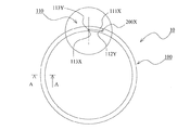
図1〜図8を参照して、本発明の実施例1に係るシールリングについて説明する。図1は本発明の実施例1に係るシールリングの側面図(概略的に示した側面図)である。図2は本発明の実施例1に係るシールリングの側面図の一部拡大図であり、図1において丸で囲った部分の拡大図である。図3は本発明の実施例1に係るシールリングの側面図の一部拡大図であり、図1において丸で囲った部分を反対側から見た拡大図である。図4は本発明の実施例1に係るシールリングを外周面側から見た図の一部拡大図であり、図1において丸で囲った部分を外周面側から見た拡大図である。図5は本発明の実施例1に係るシールリングを内周面側から見た図の一部拡大図であり、図1において丸で囲った部分を内周面側から見た拡大図である。図6〜図8は本発明の実施例1に係る密封構造(シールリングの使用時の状態)を示す模式的断面図である。なお、図6は無負荷の状態を示し、図7及び図8は差圧が生じた状態を示している。また、図6,7中のシールリングは、図1中のAA断面図に相当し、図8中のシールリングは図2中のBB断面図に相当する。Example 1
With reference to FIGS. 1-8, the seal ring which concerns on Example 1 of this invention is demonstrated. FIG. 1 is a side view (schematically shown side view) of a seal ring according to Embodiment 1 of the present invention. FIG. 2 is a partially enlarged view of a side view of the seal ring according to the first embodiment of the present invention, and is an enlarged view of a circled portion in FIG. 3 is a partially enlarged view of a side view of the seal ring according to the first embodiment of the present invention, and is an enlarged view of a circled portion in FIG. 1 as viewed from the opposite side. 4 is a partially enlarged view of the seal ring according to the first embodiment of the present invention as seen from the outer peripheral surface side, and is an enlarged view of the circled portion in FIG. 1 as seen from the outer peripheral surface side. 5 is a partially enlarged view of the seal ring according to the first embodiment of the present invention as seen from the inner peripheral surface side, and is an enlarged view of the circled portion in FIG. 1 as seen from the inner peripheral surface side. . FIGS. 6-8 is typical sectional drawing which shows the sealing structure (state at the time of use of a seal ring) based on Example 1 of this invention. FIG. 6 shows a no-load state, and FIGS. 7 and 8 show a state where a differential pressure is generated. 6 and 7 corresponds to the AA cross-sectional view in FIG. 1, and the seal ring in FIG. 8 corresponds to the BB cross-sectional view in FIG.
<密封構造及びシールリングの構成>
特に、図1及び図6〜図8を参照して、本発明の実施例1に係る密封構造及びシールリングの構成について説明する。本実施例に係る密封構造は、相対的に回転する軸600及びハウジング700と、軸600とハウジング700(ハウジング700における軸600が挿通される軸孔の内周面)との間の環状隙間を封止するシールリング10とから構成される。本実施例に係るシールリング10は、軸600の外周に設けられた環状溝610に装着され、相対的に回転する軸600とハウジング700との間の環状隙間を封止する。これにより、シールリング10は、流体圧力(本実施例では油圧)が変化するように構成された密封対象領域の流体圧力を保持する。ここで、本実施例においては、図6〜図8中の右側の領域の流体圧力が変化するように構成されており、シールリング10は図中右側の密封対象領域の流体圧力を保持する役割を担っている。なお、自動車のエンジンが停止した状態においては、密封対象領域の流体圧力は低く、無負荷の状態となっており、エンジンをかけると密封対象領域の流体圧力は高くなる。<Structure of sealing structure and seal ring>
In particular, with reference to FIG. 1 and FIGS. 6 to 8, the structure of the sealing structure and the seal ring according to the first embodiment of the present invention will be described. The sealing structure according to the present embodiment includes a
そして、本実施例に係るシールリング10は、ポリエーテルエーテルケトン(PEEK)、ポリフェニレンサルファイド(PPS)、ポリテトラフルオロエチレン(PTFE)などの樹脂製のシールリング本体100と、アクリルゴム(ACM)、フッ素ゴム(FKM)、水素化ニトリルゴム(HNBR)などのゴム状弾性体製の第1弾性体シール部200X及び第2弾性体シール部200Yとから構成される。
The
また、シールリング本体100単体における外周面の周長は、ハウジング700の軸孔の内周面の周長よりも短く設定されている。そして、シールリング本体100と第1弾性体シール部200X及び第2弾性体シール部200Yとを備えるシールリング10全体における外周面の周長は、ハウジング700の軸孔の内周面の周長よりも長く設定されている。
Further, the peripheral length of the outer peripheral surface of the
<シールリング本体>
特に、図1〜図5を参照して、本発明の実施例に係るシールリング本体100について、より詳細に説明する。シールリング本体100には、周方向の1箇所に合口部110が設けられている。本実施例に係るシールリング本体100は、断面が矩形の環状部材に対して、この合口部110が形成された構成である。ただし、これは形状についての説明に過ぎず、必ずしも、断面が矩形の環状部材を素材として、合口部110を形成する加工を施すことを意味するものではない。勿論、断面が矩形の環状部材を成形した後に、合口部110を切削加工により得ることもできるが、樹脂材料によっては、合口部110を有したものを成形することもでき、製法は特に限定されるものではない。<Seal ring body>
In particular, the
合口部110は、外周面側及び両側壁面側のいずれから見ても階段状の合わせ面(切断面)が設けられた、いわゆる特殊ステップカットを採用している。これにより、シールリング本体100においては、合わせ面を介して一方の側の外周側には第1嵌合凸部111X及び第1嵌合凹部112Xが設けられ、他方の側の外周側には第1嵌合凸部111Xが嵌る第2嵌合凹部112Yと第1嵌合凹部112Xに嵌る第2嵌合凸部111Yが設けられている。なお、合わせ面を介して一方の側の内周面側の端面113Xと他方の側の内周側の端面113Yは互いに対向している。特殊ステップカットに関しては公知技術であるので、その詳細な説明は省略するが、熱膨張収縮によりシールリング本体100の周長が変化しても安定した密封性を維持する特性を有する。なお、「合わせ面(切断面)」については、切削加工により得られる場合だけでなく、成形により得られる場合も含まれる。
The
<第1弾性体シール部及び第2弾性体シール部>
特に、図1〜図4を参照して、第1弾性体シール部200X及び第2弾性体シール部200Yについて、より詳細に説明する。<First elastic body seal part and second elastic body seal part>
In particular, the first elastic
第1嵌合凸部111Xにおける周方向先端の第1先端面111Xaと、第2嵌合凹部112Yにおいて第1先端面111Xaに対向する第1対向面112Yaとの間に、第1弾性体シール部200Xが設けられている。この第1弾性体シール部200Xは、第1先端面111Xaと第1対向面112Yaとの間の隙間を封止すると共に、第1先端面111Xaと第1対向面112Yaを周方向に対して互いに離れる方向に押圧する役割を担っている。また、第1弾性体シール部200Xは第1先端面111Xaと第1対向面112Yaのうちのいずれか一方に接着などにより固定されており、他方には固定されていない。
A first elastic seal portion between the first tip surface 111Xa at the tip in the circumferential direction of the first fitting
第2嵌合凸部111Yにおける周方向先端の第2先端面111Yaと、第1嵌合凹部112Xにおいて第2先端面111Yaに対向する第2対向面112Xaとの間に、第2弾性体シール部200Yが設けられている。この第2弾性体シール部200Yは、第2先端面111Yaと第2対向面112Xaとの間の隙間を封止すると共に、第2先端面111Yaと第2対向面112Xaを周方向に対して互いに離れる方向に押圧する役割を担っている。また、第2弾性体シール部200Yは第2先端面111Yaと第2対向面112Xaのうちのいずれか一方に、接着などにより固定されており、他方には固定されていない。
Between the second tip surface 111Ya at the circumferential tip of the second
以上のように構成される第1弾性体シール部200Xと第2弾性体シール部200Yは、シールリング本体100の合口部110における合わせ面を介して一方の端部と他方の端部に対し、これらの端部を周方向に対して互いに離れる方向に押圧する。これにより、シールリング本体100には、径が大きくなる方向に変形する力が作用する。
The first elastic
なお、本実施例に係るシールリング10においては、第1嵌合凸部111Xと第2嵌合凸部111Yと第1嵌合凹部112Xと第2嵌合凹部112Yの周方向の長さはいずれも同一となるように設定されている。そして、第1弾性体シール部200Xと第2弾性体シール部200Yの周方向の長さは同一となるように設定され、かつ第1嵌合凸部111Xの周方向の長さよりも長くなるように設定されている。これにより、合口部110における合わせ面を介して一方の側の内周面側の端面113Xと他方の側の内周側の端面113Yとの間には、シールリング本体100の熱膨張伸縮に拘わらず、隙間が確保される。
In the
<シールリングの使用時のメカニズム>
特に、図6〜図8を参照して、本実施例に係るシールリング10の使用時のメカニズムについて説明する。図6は、エンジンが停止して、シールリング10を介して左右の領域の差圧がなく(または、差圧が殆どなく)、無負荷の状態を示している。なお、図6中のシールリング本体100は、図1中のAA断面に相当する。図7及び図8は、エンジンがかかり、シールリング10を介して、左側の領域に比べて右側の領域の流体圧力の方が高くなった状態を示している。なお、図7中のシールリング本体100は図1中のAA断面に相当し、図8中のシールリング本体100は図2中のBB断面に相当する。<Mechanism when using seal ring>
In particular, a mechanism during use of the
上記の通り、本実施例に係るシールリング10においては、シールリング本体100単体における外周面の周長は、ハウジング700の軸孔の内周面の周長よりも短く設定されている。しかしながら、シールリング10全体における外周面の周長は、ハウジング700の軸孔の内周面の周長よりも長く設定されている。また、第1弾性体シール部200Xと第2弾性体シール部200Yによって、シールリング本体100には、径が大きくなる方向に変形する力が作用する。従って、無負荷状態においては、左右の領域の差圧がないものの、シールリング10の外周面は、ハウジング700の軸孔の内周面に接した状態を維持する(図6参照)。
As described above, in the
そして、エンジンがかかり、差圧が生じた状態においては、高圧側(H)からの流体圧力によって、シールリング10は、環状溝610における低圧側(L)の側壁面に密着した状態となる。なお、シールリング10は、ハウジング700における軸孔の内周面に対して接した(摺動した)状態を維持していることは言うまでもない。従って、軸600とハウジング700との間の環状隙間が封止された状態となる。また、その後、エンジンが停止して、無負荷状態になっても、シールリング本体100には、径が大きくなる方向に変形する力が作用している。そのため、シールリング10の外周面はハウジング700の軸孔の内周面に密着しており、シールリング10は軸線方向(軸600の中心軸線方向)には殆ど移動しない。つまり、シールリング10は、環状溝610における低圧側(L)の側壁面に密着した状態を維持している。従って、無負荷状態においても、軸600とハウジング700との間の環状隙間が封止された状態が維持される。
When the engine is started and a differential pressure is generated, the
<本実施例に係るシールリングの優れた点>
本実施例に係るシールリング10によれば、シールリング本体100に合口部110が設けられているものの、合口部110における隙間は、第1弾性体シール部200Xと第2弾性体シール部200Yによって封止されている。従って、シールリング本体100における合口部110の隙間から密封対象流体が漏れてしまうことが抑制される。このように、本実施例に係るシールリング10によれば、合口部110を備えていても、密封性を向上させることができる。<Excellent points of seal ring according to this embodiment>
According to the
また、本実施例に係るシールリング本体100の合口部110における合わせ面を介して一方の端部と他方の端部は、第1弾性体シール部200Xと第2弾性体シール部200Yによって、周方向に対して互いに離れる方向に押圧される。これにより、シールリング本体100には、径が大きくなる方向に変形する力が作用する。従って、流体圧力が作用してない(差圧が生じていない)、または流体圧力が殆ど作用していない(差圧が殆ど生じていない)状態においても、シールリング10を、ハウジング700の軸孔の内周面に接した状態とすることが可能となる。これにより、密封機能が発揮されるため、密封対象領域の流体圧力が高まりだした直後から流体圧力を保持させることができる。
In addition, one end and the other end of the
つまり、アイドリングストップ機能を有するエンジンにおいては、エンジン停止状態からアクセルが踏み込まれることでエンジンが始動することによって、密封対象領域側の油圧が高まりだした直後から油圧を保持させることができる。ここで、一般的には、樹脂製のシールリングの場合、流体の漏れを抑制する機能はあまり発揮されない。しかしながら、本実施例に係るシールリング10においては、無負荷状態においても、軸600とハウジング700との間の環状隙間が封止された状態が維持されるため、流体の漏れを十分抑制する機能が発揮される。そのため、エンジンが停止することでポンプなどによる作用が停止した後も、しばらくの間差圧が生じた状態を維持させることが可能となる。従って、アイドリングストップ機能を有するエンジンにおいて、エンジンの停止状態がそれほど長くない場合には、差圧が生じた状態を維持できるので、エンジンを再始動させた際に、その直後から好適に流体圧力を保持させることができる。
In other words, in an engine having an idling stop function, the hydraulic pressure can be maintained immediately after the hydraulic pressure on the sealing target region side is increased by starting the engine by depressing the accelerator when the engine is stopped. Here, generally, in the case of a resin seal ring, the function of suppressing fluid leakage is not so much exhibited. However, in the
また、本実施例に係るシールリング10においては、第1弾性体シール部200Xは第1先端面111Xaと第1対向面112Yaのうちのいずれか一方に固定されており、第2弾性体シール部200Yは第2先端面111Yaと第2対向面112Xaのうちのいずれか一方に固定されている。従って、合口部110における合わせ面を介して一方の端部と他方の端部との間に隙間を形成させることが可能となるため、シールリング10の環状溝610への装着作業を容易にすることができる。
Further, in the
また、本実施例に係るシールリング10においては、シールリング本体100単体における外周面の周長は、ハウジング700の軸孔の内周面の周長よりも短く設定されている。そして、シールリング本体100と第1弾性体シール部200X及び第2弾性体シール部200Yとを備えるシールリング10全体における外周面の周長は、ハウジング700の軸孔の内周面の周長よりも長く設定されている。これにより、シールリング10の外周面とハウジング700の軸孔内周面との間の摺動トルクを低く抑えつつ、流体圧力が作用してない(差圧が生じていない)状態においても、シールリング10を、ハウジング700の軸孔の内周面に接した状態とすることが可能となる。
Further, in the
なお、本実施例に係るシールリング10は、軸線方向の中心面に対して対称的な形状をなしている。従って、環状溝610内にシールリング10を取り付ける際に、取付方向を気にする必要がなく、装着性に優れている。また、高圧側と低圧側が入れ替わるような環境下でも用いることができる。
The
(実施例2)
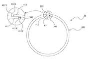
図9及び図10を参照して、本発明の実施例2に係るシールリングについて説明する。図9は本発明の実施例2に係るシールリングの側面図である。なお、図9の左上には、一部を拡大した図も示している。図10は本発明の実施例2に係るシールリングの使用時の状態を示す模式的断面図である。なお、図10中のシールリングは、図9中のCC断面図に相当する。(Example 2)
With reference to FIG.9 and FIG.10, the seal ring which concerns on Example 2 of this invention is demonstrated. FIG. 9 is a side view of a seal ring according to Embodiment 2 of the present invention. A partially enlarged view is also shown in the upper left of FIG. FIG. 10 is a schematic cross-sectional view showing a state when the seal ring according to the second embodiment of the present invention is used. The seal ring in FIG. 10 corresponds to the CC cross-sectional view in FIG.
<密封構造>
本実施例に係る密封構造においても、実施例1の場合と同様に、相対的に回転する軸600及びハウジング700と、軸600とハウジング700(ハウジング700における軸600が挿通される軸孔の内周面)との間の環状隙間を封止するシールリング30とから構成される。本実施例に係るシールリング30は、軸600の外周に設けられた環状溝610に装着され、相対的に回転する軸600とハウジング700との間の環状隙間を封止する。これにより、シールリング30は、流体圧力(本実施例では油圧)が変化するように構成された密封対象領域の流体圧力を保持する。ここで、本実施例においては、図10中の右側の領域の流体圧力が変化するように構成されており、シールリング30は図中右側の密封対象領域の流体圧力を保持する役割を担っている。なお、自動車のエンジンが停止した状態においては、密封対象領域の流体圧力は低く、無負荷の状態となっており、エンジンをかけると密封対象領域の流体圧力は高くなる。<Sealing structure>
Also in the sealing structure according to the present embodiment, as in the case of the first embodiment, the
そして、本実施例に係るシールリング30は、ポリエーテルエーテルケトン(PEEK)、ポリフェニレンサルファイド(PPS)、ポリテトラフルオロエチレン(PTFE)などの樹脂製のシールリング本体400と、金属製の弾性体としての金属バネ500とから構成される。なお、本実施例に係る金属バネ500は、図示のようにコイルスプリングを採用しているが、板バネなどを採用することもできる。
The
また、シールリング本体400単体における外周面の周長は、ハウジング700の軸孔の内周面の周長よりも短く設定されている。そして、シールリング本体400と金属バネ500とを備えるシールリング30全体における外周面の周長は、ハウジング700の軸孔の内周面の周長よりも長く設定されている。
Further, the peripheral length of the outer peripheral surface of the seal ring
<シールリング本体>
シールリング本体400には、周方向の1箇所に合口部410が設けられている。本実施例に係るシールリング本体400は、断面が矩形の環状部材に対して、この合口部410が形成された構成である。ただし、これは形状についての説明に過ぎず、必ずしも、断面が矩形の環状部材を素材として、合口部410を形成する加工を施すことを意味するものではない。勿論、断面が矩形の環状部材を成形した後に、合口部410を切削加工により得ることもできるが、樹脂材料によっては、合口部410を有したものを成形することもでき、製法は特に限定されるものではない。<Seal ring body>
The
合口部410は、両側壁面側のいずれから見ても階段状の合わせ面(切断面)が設けられた、いわゆるステップカットを採用している。これにより、シールリング本体400においては、合わせ面を介して一方の側の内周側に第1嵌合凸部411が設けられ、他方の側の外周側に第2嵌合凸部412が設けられている。なお、「合わせ面(切断面)」については、切削加工により得られる場合だけでなく、成形により得られる場合も含まれる。
The
<金属バネ(弾性体)>
合わせ面を介して一方の側の内周側に設けられた第1嵌合凸部411における周方向先端の第1先端面411Xと、合わせ面を介して他方の側の内周側の端面412Yとの間に、金属バネ500が嵌め込まれている。この金属バネ500は、第1先端面411Xと端面412Yを周方向に対して互いに離れる方向に押圧する役割を担っている。<Metal spring (elastic body)>
A
以上のように構成される金属バネ500は、シールリング本体400の合口部410における合わせ面を介して一方の端部と他方の端部に対し、これらの端部を周方向に対して互いに離れる方向に押圧する。これにより、シールリング本体400には、径が大きくなる方向に変形する力が作用する。
The
なお、合わせ面を介して他方側の外周側に設けられた第2嵌合凸部412における周方向先端の第2先端面412Xと、合わせ面を介して一方の側の外周側の端面411Yとの間に、金属バネ500が嵌め込まれる構成を採用することもできる。この場合でも、金属バネ500は、第2先端面412Xと端面411Yを周方向に対して互いに離れる方向に押圧する役割を担うことになる。また、第1先端面411Xと端面412Yとの間に金属バネ500が嵌め込まれ、かつ第2先端面412Xと端面411Yとの間に金属バネ500が嵌め込まれる構成を採用することもできる。
A
また、本実施例に係るシールリング30においては、第1嵌合凸部411と第2嵌合凸部412の周方向の長さはいずれも同一となるように設定されている。これにより、第1先端面411Xと端面412Yとの間にのみ金属バネ500が嵌め込まれている場合には、第2先端面412Xと端面411Yとの間には、シールリング本体400の熱膨張伸縮に拘わらず、隙間が確保される。また、第2先端面412Xと端面411Yとの間にのみ金属バネ500が嵌め込まれている場合には、第1先端面411Xと端面412Yとの間にとの間には、シールリング本体400の熱膨張伸縮に拘わらず、隙間が確保される。
Further, in the
シールリング30の使用時のメカニズムについては、上記実施例1の場合と同様であるので、その説明は省略する。
Since the mechanism when the
本実施例に係るシールリング30の場合には、上記実施例1の場合とは異なり、合口部410からの密封対象流体の漏れを抑制することはできない。しかしながら、本実施例に係るシールリング30においても、上記実施例1の場合と同様に、シールリング本体400の合口部410における合わせ面を介して一方の端部と他方の端部は、金属バネ500によって、周方向に対して互いに離れる方向に押圧される。これにより、シールリング本体400には、径が大きくなる方向に変形する力が作用する。従って、流体圧力が作用してない(差圧が生じていない)、または流体圧力が殆ど作用していない(差圧が殆ど生じていない)状態においても、シールリング30を、ハウジング700の軸孔の内周面に接した状態とすることが可能となる。これにより、密封機能が発揮されるため、密封対象領域の流体圧力が高まりだした直後から流体圧力を保持させることができる。
In the case of the
また、本実施例に係るシールリング30においては、金属バネ500は、シールリング本体400の合口部410に嵌合させる構成を採用している。そのため、シールリング本体400については、合口部410における合わせ面を介して一方の端部と他方の端部との間に隙間を形成させることが可能である。従って、シールリング30の環状溝610への装着作業は容易である。
In the
更に、本実施例に係るシールリング30においても、シールリング本体400単体における外周面の周長は、ハウジング700の軸孔の内周面の周長よりも短く設定されている。そして、シールリング本体400と金属バネ500とを備えるシールリング30全体における外周面の周長は、ハウジング700の軸孔の内周面の周長よりも長く設定されている。これにより、シールリング30の外周面とハウジング700の軸孔内周面との間の摺動トルクを低く抑えつつ、流体圧力が作用してない(差圧が生じていない)状態においても、シールリング30を、ハウジング700の軸孔の内周面に接した状態とすることが可能となる。
Furthermore, also in the
なお、本実施例に係るシールリング30においても、軸線方向の中心面に対して対称的な形状をなしている。従って、環状溝610内にシールリング30を取り付ける際に、取付方向を気にする必要がなく、装着性に優れている。また、高圧側と低圧側が入れ替わるような環境下でも用いることができる。
Note that the
上記実施例1においては、弾性体がゴム状弾性体製のシール部(第1弾性体シール部200X及び第2弾性体シール部200Y)の場合を示した。また、実施例2においては、弾性体が金属バネ(コイルスプリングや板バネ)の場合を示した。しかしながら、本願発明における弾性体は、適宜、各種材料を適用し得る。また、弾性体の形状においても、上記実施例で示した形状以外の各種の形状を適用し得る。
In the first embodiment, the case where the elastic body is a rubber-like elastic seal portion (the first elastic
10,30 シールリング
100,400 シールリング本体
110,410 合口部
111X 第1嵌合凸部
111Xa 第1先端面
111Y 第2嵌合凸部
111Ya 第2先端面
112X 第1嵌合凹部
112Xa 第2対向面
112Y 第2嵌合凹部
112Ya 第1対向面
113X 端面
113Y 端面
200X 第1弾性体シール部
200Y 第2弾性体シール部
411 第1嵌合凸部
411X 第1先端面
411Y 端面
412 第2嵌合凸部
412X 第2先端面
412Y 端面
500 金属バネ
600 軸
610 環状溝
700 ハウジング10, 30
Claims (5)
周方向の1箇所に合口部が設けられた樹脂製のシールリング本体と、
前記合口部における合わせ面を介して一方側の端部と他方側の端部とを周方向に対して互いに離れる方向に押圧する弾性体と、
を備えることを特徴とするシールリング。Fluid pressure in a region to be sealed, which is mounted in an annular groove provided on the outer periphery of the shaft, and is configured to seal the annular gap between the shaft and the housing that rotate relatively to change the fluid pressure. A seal ring for holding
A resin seal ring body provided with an abutment portion in one circumferential direction;
An elastic body that presses the end on one side and the end on the other side in a direction away from each other with respect to the circumferential direction via a mating surface in the joint portion;
A seal ring comprising:
第1嵌合凸部における周方向先端の第1先端面と、第2嵌合凹部において第1先端面に対向する第1対向面との間には、これら第1先端面と第1対向面を周方向に対して互いに離れる方向に押圧する前記弾性体である第1弾性体シール部が設けられ、
第2嵌合凸部における周方向先端の第2先端面と、第1嵌合凹部において第2先端面に対向する第2対向面との間には、これら第2先端面と第2対向面を周方向に対して互いに離れる方向に押圧する前記弾性体である第2弾性体シール部が設けられていることを特徴とする請求項1に記載のシールリング。The abutment portion is provided with a step-like mating surface when viewed from either the outer peripheral surface side or both side wall surfaces, so that the first fitting convex portion and the first mating portion are provided on the outer peripheral side of one side through the mating surface. 1 fitting recess is provided, and on the outer peripheral side of the other side is provided a second fitting recess that fits the first fitting projection and a second fitting projection that fits the first fitting recess,
Between the first tip surface at the tip in the circumferential direction of the first fitting convex portion and the first opposing surface facing the first tip surface in the second fitting concave portion, these first tip surface and first opposing surface. Is provided with a first elastic body seal portion that is an elastic body that presses in a direction away from each other in the circumferential direction,
Between the second tip surface at the tip in the circumferential direction of the second fitting convex portion and the second facing surface facing the second tip surface in the first fitting concave portion, the second tip surface and the second facing surface. 2. The seal ring according to claim 1, wherein a second elastic body seal portion that is the elastic body that presses the first and second elastic bodies in a direction away from each other in the circumferential direction is provided.
Applications Claiming Priority (5)
| Application Number | Priority Date | Filing Date | Title |
|---|---|---|---|
| JP2015202028 | 2015-10-13 | ||
| JP2015202028 | 2015-10-13 | ||
| JP2016019606 | 2016-02-04 | ||
| JP2016019606 | 2016-02-04 | ||
| PCT/JP2016/080044 WO2017065120A1 (en) | 2015-10-13 | 2016-10-11 | Seal ring |
Publications (2)
| Publication Number | Publication Date |
|---|---|
| JPWO2017065120A1 JPWO2017065120A1 (en) | 2018-08-02 |
| JP6566040B2 true JP6566040B2 (en) | 2019-08-28 |
Family
ID=58517569
Family Applications (1)
| Application Number | Title | Priority Date | Filing Date |
|---|---|---|---|
| JP2017545190A Active JP6566040B2 (en) | 2015-10-13 | 2016-10-11 | Seal ring |
Country Status (6)
| Country | Link |
|---|---|
| US (1) | US20180306325A1 (en) |
| EP (1) | EP3364079B1 (en) |
| JP (1) | JP6566040B2 (en) |
| KR (1) | KR102038238B1 (en) |
| CN (1) | CN108138962A (en) |
| WO (1) | WO2017065120A1 (en) |
Family Cites Families (35)
| Publication number | Priority date | Publication date | Assignee | Title |
|---|---|---|---|---|
| US50697A (en) * | 1865-10-31 | Improvement in metallic packing for steam-pistons | ||
| US1211344A (en) * | 1916-10-13 | 1917-01-02 | Matthew J Peters | Packing-ring. |
| US1489335A (en) * | 1920-06-17 | 1924-04-08 | Seifert Henry Richard | Piston ring |
| US1438763A (en) * | 1922-04-24 | 1922-12-12 | William H Stehle | Piston ring |
| US1696424A (en) * | 1924-09-18 | 1928-12-25 | Thompson James Horace | Compression and suction saving construction for piston rings |
| US2083237A (en) * | 1934-05-23 | 1937-06-08 | Ernest C Norton | Piston ring |
| US2107301A (en) * | 1935-08-01 | 1938-02-08 | Koppers Co Inc | Piston ring |
| US2459642A (en) * | 1943-03-01 | 1949-01-18 | Rodpak Mfg Co | Seal |
| US2515629A (en) * | 1945-02-09 | 1950-07-18 | Garlock Packing Co | Garter spring |
| US2738243A (en) * | 1952-12-24 | 1956-03-13 | Auto Diesel Piston Ring Compan | Sealing ring |
| JPS4822995Y1 (en) * | 1970-03-27 | 1973-07-04 | ||
| US4109924A (en) * | 1976-07-12 | 1978-08-29 | Chemprene, Inc. | Stepped joint piston ring |
| US4206930A (en) * | 1977-05-31 | 1980-06-10 | Chemprene, Inc. | Circumferentially compressed piston ring assembly and method |
| US4570945A (en) * | 1982-05-20 | 1986-02-18 | Nissan Motor Co., Ltd. | Piston ring having shape of an ellipse or an elongated circle |
| JPS6081257U (en) * | 1983-11-08 | 1985-06-05 | 三菱自動車工業株式会社 | piston ring |
| US4652000A (en) * | 1986-07-21 | 1987-03-24 | Ex-Cell-O Corporation | Sealing system for high pressure gas applications |
| JPH0398361U (en) * | 1990-01-29 | 1991-10-11 | ||
| US5395124A (en) * | 1993-01-04 | 1995-03-07 | Imo Industries, Inc. | Retractible segmented packing ring for fluid turbines having gravity springs to neutralize packing segment weight forces |
| CN1037369C (en) * | 1993-05-10 | 1998-02-11 | 董瑞 | New-type piston-ring |
| JPH07332495A (en) * | 1994-06-10 | 1995-12-22 | Riken Corp | Piston ring for internal combustion engine |
| US6318728B1 (en) * | 1997-07-11 | 2001-11-20 | Demag Delaval Turbomachinery Corporation | Brush-seal designs for elastic fluid turbines |
| US5934685A (en) * | 1997-07-14 | 1999-08-10 | Danzer; Edward Leo | Step lock piston ring insert |
| US6572114B1 (en) * | 1997-09-22 | 2003-06-03 | Mitsubishi Heavy Industries, Ltd. | Seal ring for steam turbine |
| US6220603B1 (en) * | 1998-07-13 | 2001-04-24 | Ronald Earl Brandon | Non retractable segmented packing ring for fluid turbines having special springs to reduce forces during shaft rubbing |
| JP2002372154A (en) | 2001-06-13 | 2002-12-26 | Nok Corp | Seal ring |
| US6588764B2 (en) * | 2001-11-20 | 2003-07-08 | Dresser-Rand Company | Segmented labyrinth seal assembly and method |
| US20080042369A1 (en) * | 2006-05-04 | 2008-02-21 | Krywitsky Lee A | Stuffing box with wear indicator |
| US20070296161A1 (en) * | 2006-06-21 | 2007-12-27 | Dudman Richard L | Seal, Sealing System, and Method for Sealing |
| JP2008111477A (en) | 2006-10-30 | 2008-05-15 | Ntn Corp | Seal ring |
| JP5029044B2 (en) | 2007-02-01 | 2012-09-19 | Nok株式会社 | Seal ring |
| JP5292902B2 (en) * | 2008-04-15 | 2013-09-18 | Nok株式会社 | How to install the seal ring |
| JP5273243B2 (en) * | 2009-04-07 | 2013-08-28 | Nok株式会社 | Sealing device |
| WO2012094153A2 (en) * | 2011-01-07 | 2012-07-12 | Borgwarner Inc. | Spring biased sealing method for an actuating shaft |
| CN202612607U (en) * | 2012-05-14 | 2012-12-19 | 镇江瑞昊工程塑料有限公司 | Lapped sealing ring |
| JP6032347B2 (en) * | 2013-02-20 | 2016-11-24 | Nok株式会社 | Sealing device |
-
2016
- 2016-10-11 JP JP2017545190A patent/JP6566040B2/en active Active
- 2016-10-11 WO PCT/JP2016/080044 patent/WO2017065120A1/en active Application Filing
- 2016-10-11 EP EP16855374.1A patent/EP3364079B1/en active Active
- 2016-10-11 KR KR1020187009863A patent/KR102038238B1/en active IP Right Grant
- 2016-10-11 CN CN201680059763.0A patent/CN108138962A/en active Pending
- 2016-10-11 US US15/767,574 patent/US20180306325A1/en not_active Abandoned
Also Published As
| Publication number | Publication date |
|---|---|
| EP3364079B1 (en) | 2020-09-02 |
| CN108138962A (en) | 2018-06-08 |
| EP3364079A4 (en) | 2019-06-12 |
| JPWO2017065120A1 (en) | 2018-08-02 |
| KR102038238B1 (en) | 2019-11-26 |
| WO2017065120A1 (en) | 2017-04-20 |
| EP3364079A1 (en) | 2018-08-22 |
| US20180306325A1 (en) | 2018-10-25 |
| KR20180050397A (en) | 2018-05-14 |
Similar Documents
| Publication | Publication Date | Title |
|---|---|---|
| US10359114B2 (en) | Sealing device | |
| JP2013194884A (en) | Sealing device | |
| CN107314111B (en) | Sealing ring and sealing structure | |
| JP5531386B2 (en) | Sealing system | |
| JP6566040B2 (en) | Seal ring | |
| WO2014045838A1 (en) | Sealing device | |
| JP6432670B2 (en) | Sealing device and sealing structure | |
| JP5545420B1 (en) | Seal ring | |
| JP6458905B2 (en) | Seal ring | |
| JP2017133571A (en) | Sealing device | |
| JP6677009B2 (en) | Sealed structure | |
| JP6170271B2 (en) | Seal ring | |
| JP2017145878A (en) | Sealing device and sealing structure | |
| JP2017125570A (en) | Sealing device | |
| JP6623775B2 (en) | Sealed structure | |
| JP2013194764A (en) | Sealing device and sealing structure | |
| JP2017122474A (en) | Sealing structure | |
| JP2013072472A (en) | Sealing device | |
| JP2017150594A (en) | Sealing structure | |
| JP2017150590A (en) | Sealing device | |
| JP2014109347A (en) | Sealing structure | |
| JP2017155771A (en) | Seal and seal structure | |
| JP2014062575A (en) | Sealing device | |
| JP2012154352A (en) | Airtight device | |
| JP2019094939A (en) | Sealing structure |
Legal Events
| Date | Code | Title | Description |
|---|---|---|---|
| A621 | Written request for application examination |
Free format text: JAPANESE INTERMEDIATE CODE: A621 Effective date: 20180330 |
|
| A131 | Notification of reasons for refusal |
Free format text: JAPANESE INTERMEDIATE CODE: A131 Effective date: 20181204 |
|
| RD03 | Notification of appointment of power of attorney |
Free format text: JAPANESE INTERMEDIATE CODE: A7423 Effective date: 20190118 |
|
| TRDD | Decision of grant or rejection written | ||
| A01 | Written decision to grant a patent or to grant a registration (utility model) |
Free format text: JAPANESE INTERMEDIATE CODE: A01 Effective date: 20190702 |
|
| A61 | First payment of annual fees (during grant procedure) |
Free format text: JAPANESE INTERMEDIATE CODE: A61 Effective date: 20190715 |
|
| R150 | Certificate of patent or registration of utility model |
Ref document number: 6566040 Country of ref document: JP Free format text: JAPANESE INTERMEDIATE CODE: R150 |
|
| R250 | Receipt of annual fees |
Free format text: JAPANESE INTERMEDIATE CODE: R250 |