JP6564626B2 - Light source unit and lighting device - Google Patents
Light source unit and lighting device Download PDFInfo
- Publication number
- JP6564626B2 JP6564626B2 JP2015121667A JP2015121667A JP6564626B2 JP 6564626 B2 JP6564626 B2 JP 6564626B2 JP 2015121667 A JP2015121667 A JP 2015121667A JP 2015121667 A JP2015121667 A JP 2015121667A JP 6564626 B2 JP6564626 B2 JP 6564626B2
- Authority
- JP
- Japan
- Prior art keywords
- light source
- source unit
- instrument body
- leaf spring
- connector
- Prior art date
- Legal status (The legal status is an assumption and is not a legal conclusion. Google has not performed a legal analysis and makes no representation as to the accuracy of the status listed.)
- Active
Links
Images


Description
本発明は、発光素子が実装された光源ユニットと、この光源ユニットを取り付けるための器具本体とを有する照明装置に関する。 The present invention relates to a lighting device having a light source unit on which a light emitting element is mounted and a fixture body for mounting the light source unit.
従来、発光モジュールおよび直流電源装置を内蔵する長尺状の光源部と、この光源部の一部が挿入される凹部を有する器具本体部とを備える照明器具であって、光源部が器具本体部に着脱自在に取り付けられる照明器具がある(例えば、特許文献1〜3参照)。
2. Description of the Related Art Conventionally, there is a lighting fixture including a long light source unit that incorporates a light emitting module and a DC power supply device, and a fixture main unit having a recess into which a part of the light source unit is inserted. There is a lighting fixture that can be detachably attached to (see, for example,
特許文献1に記載されているカバー部材は、長尺状に形成された器具本体の一面に設けられた収容凹部に光源ユニットを収容した状態では、器具本体の長手方向及び幅方向と直交する方向において前記一対の延出部の各々が前記収容凹部の開口端縁とが生じないように重なっている。
よって、長期間使用されるなどして、この隙間に埃などが溜まった場合に側方方向への光束が徐々に低下してしまい光学特性および意匠性での点で課題があった。
The cover member described in
Therefore, when dust or the like accumulates in this gap after being used for a long period of time, the light flux in the lateral direction gradually decreases, and there is a problem in terms of optical characteristics and design properties.
さらに、特許文献1に記載されているカバー部は、光源部が器具本体部に照射側と反対側の一部を凹部に挿入し取り付けられた時に、凹部の開口端縁と隙間がないように重なる延出部を有している。
このため、光源部を器具本体部から取り外す時は、作業者が光源部を掴む箇所がなく、作業がしにくかった。
Furthermore, the cover part described in
For this reason, when removing a light source part from an instrument main-body part, there was no place for an operator to grasp a light source part, and it was difficult to work.
特許文献2に記載されている照明器具は、光源部の長手側辺と凹部の長手側壁部との間に隙間が形成されるように光源部が器具本体部に取り付けられている。
光源部は、この隙間に専用の治具を挿し込むことで器具本体部から取り外すことができるが、専用の治具を必要とする為、作業に手間がかかった。
また、器具本体に光源部を取付ける場合、係止壁の引掛け部を孔に引掛けて、引掛け部を支点として光源部を回動して取付けして取り付けられる。このため、長手方向に沿って光源部と凹部の間に形成された両側の隙間が、光源部を発光させた際にアンバランスな暗がりになるおそれがあり、意匠性の点で課題があった。
In the lighting fixture described in Patent Literature 2, the light source unit is attached to the fixture main body so that a gap is formed between the longitudinal side of the light source unit and the longitudinal side wall of the recess.
The light source part can be removed from the instrument main body part by inserting a dedicated jig into the gap, but it requires a lot of work because it requires a dedicated jig.
Further, when the light source part is attached to the instrument body, the light source part is pivotally attached by attaching the hook part of the locking wall to the hole and turning the hook part as a fulcrum. For this reason, the gaps on both sides formed between the light source part and the recesses along the longitudinal direction may cause unbalanced darkness when the light source part emits light, which is problematic in terms of design. .
本発明は、光源ユニットを器具本体に対して適切な位置に位置決めできる光源ユニット、照明装置を提供することを目的とする。 An object of this invention is to provide the light source unit which can position a light source unit in a suitable position with respect to an instrument main body, and an illuminating device.
この発明の光源ユニットは、
長手形状の器具本体に取り付けられる光源ユニットにおいて、
前記器具本体に配置された器具側取付部と連結された状態で弾性力によって前記器具本体の方向に引っ張られると共に、前記器具本体の短手方向に対する位置が決められる光源側取付部を備え、
前記器具側取付部は、板ばねであり、
前記光源側取付部は、前記板ばねが連結される連結具であり、
前記連結具は、
板状をなし、前記板ばねが挿入される開口が形成されると共に、前記器具本体に形成された器具側嵌合部に嵌められた状態で前記器具側嵌合部に拘束される連結側嵌合部を有する板部を備える。
The light source unit of the present invention is
In the light source unit attached to the longitudinally shaped instrument body,
The light source side mounting portion that is pulled in the direction of the device main body by an elastic force in a state of being connected to the device side mounting portion arranged in the device main body, and that determines the position of the device main body in the short direction ,
The appliance side mounting portion is a leaf spring,
The light source side mounting portion is a connector to which the leaf spring is connected,
The connector is
Connection side fitting which is plate-shaped and has an opening into which the leaf spring is inserted and which is constrained by the instrument side fitting part in a state of being fitted to the instrument side fitting part formed in the instrument body The board part which has a joint part is provided.
本発明によれば、記器具本体の短手方向に対する位置決めをする光源側取付部を備えたので、光源ユニットを器具本体に対して適切な位置に位置決めできる。 According to the present invention, since the light source side mounting portion for positioning the instrument body in the short direction is provided, the light source unit can be positioned at an appropriate position with respect to the instrument body.
以下、本発明の実施の形態について、図面を用いて説明する。なお、以下に説明する実施の形態によって本発明が限定されない。また、以下の図面では各構成部の大きさの関係が実際のものとは異なる場合がある。また、実施の形態の説明において、「上」、「下」、「左」、「右」、「前」、「後」、「表」、「裏」といった方向や位置が示されている場合、それらの表記は、説明の便宜上、そのように記載しているだけであって、装置、器具、部品等の配置や向き等を限定しない。 Hereinafter, embodiments of the present invention will be described with reference to the drawings. The present invention is not limited by the embodiments described below. Moreover, in the following drawings, the relationship of the size of each component may be different from the actual one. Also, in the description of the embodiment, directions and positions such as “top”, “bottom”, “left”, “right”, “front”, “back”, “front”, “back” are indicated. These notations are merely described as such for convenience of explanation, and do not limit the arrangement or orientation of devices, instruments, parts, and the like.
実施の形態1.
<***構成の説明***>
図1〜図19を参照して実施の形態1を説明する。
<*** Explanation of configuration *****>
The first embodiment will be described with reference to FIGS.
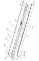
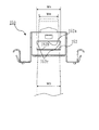
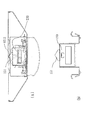
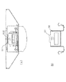
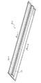
図1は照明装置10の斜視図である。図2は、照明装置10を光源ユニット100と器具本体200に分解した分割斜視図である。図3は、器具本体200に光源ユニット100を取り付ける途中を示す図である。
FIG. 1 is a perspective view of the
<照明装置10>
図1に示すように、照明装置10は、天井、壁などの図14に示す取付部300に取り付けられる長手形状の照明装置であり、長手方向Xに延びた長尺状の照明装置である。なお、光源ユニット100、器具本体200も同様に照明装置10の長手方向Xに沿った長手形状である。光源ユニット100、器具本体200の長手方向、短手方向は、照明装置10と同様に、長手方向X、短手方向Yと呼ぶ。図1〜図3に示すように、照明装置10は、光源ユニット100と、光源ユニット100が着脱可能に取り付けられる器具本体200とを備える。
照明装置10は、器具本体200と光源ユニット100との位置関係は、前者が上で、後者が下であってもよいし、両者が左右に位置するような関係であってもよいし、互いに斜めに位置するような関係であってもよい。また、この照明装置10は、長手方向あるいは短手方向に複数連結して使用される場合がある。
<
As shown in FIG. 1, the illuminating
In the illuminating
照明装置10は、長手形状の器具本体200と、器具本体200に取り付けられる光源ユニット100と、光源ユニット100を弾性力によって器具本体200の方向に引っ張ると共に、器具本体200の短手方向Yに対する光源ユニット100の位置を決める引張機構部9010を備える。引張機構部9010は後述のように板ばね230と連結具150により構成される。また、引張機構部9010は後述のように、光源ユニット100を弾性力によって器具本体200の方向に引っ張ると共に、光源ユニット100の器具本体200の長手方向Xまわりの取り付け角度を決める。
The illuminating
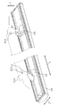
<光源ユニット100>
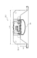
図4は、光源ユニット100の分解斜視図である。図5は、光源ユニット100の斜視図である。図6は、連結具150の斜視図である。図4、図5に示すように、光源ユニット100は、プレート部110、発光素子基板120、カバー130、電源装置140、2つの連結具150を有する。プレート部110は、長手方向に延びた板状の平面部111を有する。平面部111の一面側は、発光素子120aが実装された発光素子基板120が取り付けられる基板取付面部111aである。他面は電源装置140、連結具150が取り付けられる電源取付面部111bである。
また、プレート部110は、長手方向Xに延びる側壁をなす一対のプレート側部112を備える。プレート側部112の端部には、カバー係合部133と係合するプレート係合部112aが形成されている。
<
FIG. 4 is an exploded perspective view of the
The
光源ユニット100は長手形状の器具本体200に取り付けられる。光源ユニット100は、器具本体200に配置された器具側取付部9200と連結することで弾性力によって器具本体200の方向に引っ張られると共に、器具本体200の短手方向Yに対する位置決めをする光源側取付部9100を備える。実施の形態1では、板ばね230を器具側取付部9200として、板ばね230と連結する連結具150を光源側取付部9100として説明するが、後述する実施の形態4の最後に記載しているように、板ばね230を光源ユニット100に配置し、連結具150を器具本体200に配置してもよい。その場合、板ばね230が光源側取付部9100であり、連結具150が器具側取付部9200である。なお、板ばね230と連結具150は作用反作用で互いに引っ張りあうため、一方は他方に引っ張られる。つまり、連結具150は板ばね230に引っ張られるし、板ばね230は連結具150に引っ張られる。
The
また光源側取付部9100は、器具本体200に対する器具本体200の長手方向Xまわりの取り付け角度を決める。
The light source side attachment portion 9100 determines an attachment angle around the longitudinal direction X of the
<プレート部110>
図4に示すように、プレート部110は、長尺状の平板である平面部111と、平面部111の短手方向の両端が折り曲げられて形成されるプレート側部112とを有し、短手方向に切る断面が略コ字形状である。基板取付面部111aには、発光素子基板120が取り付けられる。また、基板取付面部111aの裏面である電源取付面部111bには、発光素子基板120に電力を供給する電源装置140と、2つの連結具150とが取り付けられる。
<
As shown in FIG. 4, the
<発光素子基板120>
図4に示すように、光源ユニット100は、発光素子120aとしてLED素子が用いられている。詳しくは、波長が440〜480〔nm〕の青色光を出射するLEDチップ上に青色光を黄色光に波長変換する蛍光体を配してパッケージ化された面実装部品である疑似白色LED素子が用いられる。
<Light emitting
As shown in FIG. 4, the
なお、発光素子120aの数、種類、配置される位置は照明装置10または光源ユニット100の用途に応じて決定されるものであって、発光素子120aの数、種類、配置される位置は限定されない。
例えば、発光素子120aであるLEDはパッケージ化された面実装部品以外の砲弾型、COBなどの態様であってもよい。また、光源ユニット100は、LED素子以外の光源素子を用いたものであってもよく、例えば、有機エレクトロルミネッセンス(Organic−Electroluminescence;以下、有機ELと称する)、レーザダイオード(LD)などの固体発光素子を使用することもできる。
詳しくは、長手方向の長さが基板120bまたはプレート部110の長手方向の長さと略等しい、長尺の有機EL素子1つを発光素子120aとして用い、有機EL素子の長手方向と基板120bまたはプレート部110の長手方向が並行になるように配置してもよい。
Note that the number, type, and positions of the
For example, the LED that is the
Specifically, a long organic EL element whose length in the longitudinal direction is substantially equal to the length in the longitudinal direction of the
また、実施の形態1に係る発光素子120aから出射する光は、発光面に垂直な軸に対して対称に照射角αだけ広がる。実施の形態1ではこの照射角αは120度である。
Further, the light emitted from the
<カバー130>
図4に示すように、カバー130は、発光素子120aを覆って長手方向に延びる。また、カバー130は、発光素子120aの発光面と対向するカバー前面部132とカバー前面部132の短手方向Yの両端部と繋がるカバー側部131とを有する。カバー130は、カバー側部131がプレート部110の短手方向Yの端部であるプレート側部112を覆うようにしてプレート部110に取り付けられる。
<Cover 130>
As shown in FIG. 4, the
カバー130は、プレート部110に取り付けられた発光素子基板120を覆うようにプレート部110に取り付けられる。詳しくは、カバー側部131の端部に設けられたカバー係合部133が、プレート側部112の先端に設けられたプレート係合部112aに取り付けられることによって、カバー130がプレート部110に固定される。
The
カバー130は、樹脂材料を用いて押出成形などの方法で製造される。カバー130は、全体が透光性の樹脂材料を用いて形成されてもよいし、一部が遮光性の樹脂材料を用いて形成されてもよい。カバー130の長手方向の両端部には、端部カバー134が取り付けられる。
The
<電源装置140>
電源装置140は、平面部111の電源取付面部111bに取り付けられている。
<
The
<連結具150>
図7は連結具150の6面図である。2つの連結具150は、平面部111の他面側である電源取付面部111bの長手方向Xの両端部側にそれぞれ取り付けられている。連結具150は、後述する器具本体200の板ばね230とともに、光源ユニット100を引っ張ることで器具本体200に取り付ける引張機構部9010を構成する。連結具150は、後述する器具本体200が備える板ばね230に連結し、光源ユニット100を器具本体200に固定する。
<
FIG. 7 is a six-side view of the
連結具150は、光源ユニット100の形状に応じて設置される数が変更することができる。光源ユニット100の長手方向の長さが短い場合は、長手方向の一端部のみに連結具150を設置し他端部はフックなどで固定する機構としてもよい。また、光源ユニット100の長手方向の長さが長い場合は、長手方向の両端部側と中央部に3つ以上の連結具150を設置してもよい。
The number of
2つの連結具150はいずれも略L形状をなしている。連結具150は、取付方向に立ち上がる板部1501と、板部1501の短手方向の両側に設けられた取付部材153と、板部1501の下辺部に設けられた連結具150をねじ止めするためのねじ止め部154とを備える。取付部材153は、プレート部110に形成された図示していない係合部と係合して、連結具150をプレート部110に係止する。図6に示すように、ねじ止め部154は、プレート部110の電源取付面部111bに取付け部110cにねじ止めされる。板部1501には、後述する板ばねを挿入する開口152が形成される。
The two connecting
後述の図16のように、連結具150は、板状をなし、板ばね230が挿入される開口152であって板ばね230が当接する縁9152aの幅の両端9152cで板ばね230を拘束する開口152が形成された板部1501を有する。縁9152aとは上辺部152aであり、幅の両端9152cとは両側の側辺部152cのうち、上辺部152aの端と角を作る部分である。
As will be described later with reference to FIG. 16, the
図15、図16で後述するが、開口152は、後述する板ばね230を連結具150に連結させる。実施の形態1における開口152は台形形状をしており、下辺部152bの長さ寸法W1に対して上辺部152aの長さ寸法W2が小さく、両側の側辺部152cが下辺部152bから上辺部152aに向って徐々に窄まるように形成されている。上辺部152aおよび下辺部152bは電源取付面部111bに沿っており、光源ユニット100を器具本体200に取り付けたり取り外したりする挿抜方向Zと直交する。また、上辺部152aおよび下辺部152bは後述する板ばね230に沿っている。
As will be described later with reference to FIGS. 15 and 16, the
図8は、連結具150の開口形状のバリエーションを示す図である。図8(a)に示すように、上辺部152aと下辺部152bとを繋ぐ両側の側辺部152cは直線状でもよいが、これに限らず曲線状であってもよいし、直線状の部分と曲線状の部分とを組み合せてもよい。
図8(b)(c)はそれぞれ、側辺部152cが全部曲線、側辺部152cのうち破線部分が曲線の場合を示す。
FIG. 8 is a view showing variations in the opening shape of the
FIGS. 8B and 8C show cases where the
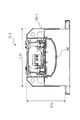
<器具本体200>
図11は、器具本体200の斜視図である。器具本体200は、本体部210と、本体部210の両端部に取り付けられる端板部220とを備える。器具本体200は長手形状である。本体部210は、短手方向の断面形状がコの字状に折り曲げられて形成され、長手方向Xに延びた凹部211を備える。実施の形態1では、本体部210は、板金が折り曲げられて形成される。なお、器具本体200を形成する本体部210および端板部220は、金属以外の材料を用いて形成されてもよく、例えば、樹脂材料を用いて形成されていてもよい。図2に示すように、器具本体200にはa,b,c,dの矩形をなす開口が形成されており、この開口から光源ユニット100の一部が収納される。
<
FIG. 11 is a perspective view of the
凹部211は、長手方向に延びた底面部211aと、底面部211aの短手方向の両端部を基端部として立ち上がる側面部211bとを備える。また、本体部210は、傾斜部211dを備える。
The concave portion 211 includes a
凹部211の底面部211aには、端子台240と、2つの板ばね230が設置される。端子台240は、電源端子台である。あるいは、端子台240は信号端子台でも構わない。板ばね230は、上述した光源ユニット100が備える連結具150に対応する位置に配置される。
A
<板ばね230>
図9は、板ばね230の正面図である。図10は、板ばね230の斜視図である。実施の形態1では、図15、図16で後述するが、板ばね230の幅寸法は全体にわたって同じ寸法W3である。
<
FIG. 9 is a front view of the
板ばね230は、ステンレス材料や、バネ鋼板などの弾性材料で形成された、長手形状の板バネである。板ばね230は、第1平坦部L1、第1曲げ部M1、第2平坦部L2、第2曲げ部M2、第3平坦部L3、第3曲げ部M3、第4平坦部L4、第4曲げ部M4、円弧部E、屈曲部Kを備える。第1平坦部L1は、凹部211の底面部211aに固定される固定部231である。円弧形状部232が、第1曲げ部M1、第2平坦部L2、第2曲げ部M2、第3平坦部L3、第3曲げ部M3、第4平坦部L4、第4曲げ部M4、円弧部Eによって構成される。屈曲部Kは先端部233である。
(1)第1平坦部L1は、長手形状の一方の端部から長手方向に向かう。第1平坦部L1はねじで底面部211aに固定される。
(2)第1曲げ部M1は、第1平坦部L1の終わりに、第1曲げ半径R1で形成される。(3)第2平坦部L2は、第1曲げ半径R1で第1角度θ1に曲げられて第1平坦部L1から立ち上がる。第2平坦部L2は、可動の軸になる。
(4)第2曲げ部M2は、第2平坦部L2の終わりに、第1曲げ半径R1と反対向きに第2曲げ半径R2で形成される。
(5)第3平坦部L3は、第2曲げ半径R2で鋭角の第2角度θ2に曲げられて延びる。(6)第3曲げ部M3は、第3平坦部L3の終わりに、第2曲げ半径R2と反対向きに第3曲げ半径R3で形成される。第3曲げ部M3は、光源ユニット100が器具本体200に装着完了となる直前に連結具150の板部1501に当たることで、円弧部Eの摺動を制御する。
(7)第4平坦部L4は、第3曲げ半径R3で鋭角の第3角度θ3に曲げられて延びる。(8)第4曲げ部M4は、第4平坦部L4の終わりに、第3曲げ半径R3と反対向きに第4曲げ半径R4で形成される。
(9)円弧部Eは、第4曲げ半径R4で鈍角の第4角度θ4に曲げられて第1平坦部L1の向かう長手方向に延びると共に第2平坦部L2の立ち上がる方向に凸となる円弧形状の部分である。円弧部Eは、連結具150の上辺部152aと当接して摺動する摺動部である。
(10)屈曲部Kは、円弧部Eの端部が屈曲されたものであり、連結具150の上辺部152aに引っ掛けられる。
The
(1) The 1st flat part L1 goes to a longitudinal direction from one edge part of a longitudinal shape. The first flat portion L1 is fixed to the
(2) The first bending portion M1 is formed with the first bending radius R1 at the end of the first flat portion L1. (3) The second flat portion L2 is bent at the first angle θ1 with the first bending radius R1 and rises from the first flat portion L1. The second flat portion L2 becomes a movable axis.
(4) The second bending portion M2 is formed at the end of the second flat portion L2 with the second bending radius R2 in the direction opposite to the first bending radius R1.
(5) The third flat portion L3 is bent and extended to the acute second angle θ2 with the second bending radius R2. (6) The third bending portion M3 is formed at the end of the third flat portion L3 with the third bending radius R3 in the direction opposite to the second bending radius R2. The third bending portion M3 controls the sliding of the arc portion E by hitting the
(7) The fourth flat portion L4 is bent and extended to the acute third angle θ3 with the third bending radius R3. (8) The fourth bending portion M4 is formed at the end of the fourth flat portion L4 with the fourth bending radius R4 in the direction opposite to the third bending radius R3.
(9) The arc portion E is bent into the obtuse fourth angle θ4 with the fourth bending radius R4, extends in the longitudinal direction toward the first flat portion L1, and is convex in the rising direction of the second flat portion L2. It is a part of. The arc portion E is a sliding portion that slides in contact with the
(10) The bent portion K is formed by bending the end of the arc portion E and is hooked on the
第2平坦部L2は、板ばね230が光源ユニット100を引っ張る弾性作用時の可動軸になる。
The second flat portion L2 serves as a movable shaft during the elastic action of the
板ばね230は、光源ユニット100の連結具150とともに、照明装置10の引張機構部9010を構成する。引張機構部9010は、器具本体200に配置される板ばね230と、光源ユニット100に配置され、板ばね230と連結することで光源ユニット100を器具本体200の方向に引っ張る連結具150とを備える。連結具150は板部1501を有するが、板部1501は、板状をなし、板ばね230が挿入される開口152であり板ばね230が当接する縁9152aの幅の両端9152cで板ばね230を拘束する開口152が形成されている。
The
なお、板ばね230は、器具本体200の形状に応じて設置される数を変更することができる。器具本体200の長手方向の長さが短い場合は、長手方向の一端部のみに板ばね230を設置し他端部はフックなどで固定する機構としてもよい。また、器具本体200の長手方向の長さが長い場合は、長手方向の両端部と中央部に板ばね230を設置してもよい。中央部に板ばね230を設置する場合は、板ばね230および板ばね230に対応する光源ユニット100が備える連結具150が、光源ユニット100に取り付けられる電源装置140と干渉しない位置を選択する。
The number of
<端子台240>
端子台240には外部電源に接続される電源電線が接続される。また、端子台240には器具本体200を長手方向に連結した場合に隣接する器具本体に電力や信号を送る送り電線が接続される。よって、凹部211内には、電源電線、送り電線が配設される。
<Terminal block 240>
A power supply wire connected to an external power source is connected to the
<光源ユニット100の取り付け作業>
次に、図12〜図14を用いて、作業者が、天井などの取付部300に予め取り付けられた器具本体200に対して、光源ユニット100を取り付ける作業を説明する。図12は、光源ユニット100が器具本体200に取り付けられる前の状態を示す。図13は、光源ユニット100の器具本体200への取付工程を説明する図である。図14は、光源ユニット100の器具本体200への取り付け後における断面を示す。図14(a)は短手方向Yを法線方向とする面による断面であり、図14(b)は長手方向Xを法線方向とする面による断面である。ここで、器具本体200の取付部300への取り付けは、天井から吊り下げられている吊ボルトに固定する方法、ねじなどの固定具により直接天井に固定する方法などがある。
図13において、
(a)は、光源ユニット100が器具本体200に取り付けられる前の状態を示す。
(b)は、作業者が板ばね230の円弧部Eの曲率が大きくなるように、板ばね230を弾性変形させた状態で光源ユニット100の先端部233を連結具150に連結した状態を示す。
(c)は、円弧部Eの裏側Eaが連結具150の上辺部152aに対して摺動する状態を示す。
(d)は、光源ユニット100が器具本体200に取り付けられた状態を示す。
<Attaching work of the
Next, an operation of attaching the
In FIG.
(A) shows the state before the
(B) shows the state in which the operator has connected the
(C) shows a state in which the back side Ea of the arc part E slides with respect to the
(D) shows a state in which the
(図13(a))
図13(a)において、器具本体200では、底面部211aに板ばね230の固定部231がねじにより固定されている。光源ユニット100は器具本体200に取り付けられていない状態である。
(Fig. 13 (a))
13A, in the instrument
(図13(b))
次に、図13(b)では、板ばね230が、第2平坦部L2を回転の中心として、円弧部Eが底面部211aに対して略垂直状態になるように弾性変形した状態である。
作業者は、両方の連結具150について、開口152に板ばね230の先端部233から板ばね230をくぐらせる。作業者は、板ばね230の先端部233を、連結具150の開口152の上辺部152aに引っ掛けて、光源ユニット100を器具本体200に吊り下げる。この状態は光源ユニット100の仮取付状態である。2つの板ばね230は、器具本体200の両端部分に配置されており、光源ユニット100は2つの板ばね230で器具本体200に対して略平行な状態で姿勢を維持して吊り下げられる。
(Fig. 13 (b))
Next, in FIG. 13B, the
An operator causes the
(図13(c))
次に、図13(c)において、作業者が、カバー側部131をつかんで光源ユニット100を取付側(上方)に持ち上げると、板ばね230の円弧部Eの裏面Eaが、開口152の上辺部152aに対して、バネの復元力によって摺動する。この板ばね230の円弧部Eの摺動作用は、作業者が光源ユニット100を取付側(上方)に持ち上げると、板ばね230が自ら元の形状に戻ろうとすることによるが、作業者が板ばね230を気にすることなく、板ばね230は連結具150に対して摺動しながら元の形状に戻る。
(Fig. 13 (c))
Next, in FIG. 13C, when the operator grasps the
(図13(d))
次に、図13(d)において、作業者が、器具本体200の凹部211に光源ユニット100を押し上げると、連結具150の上端部151が凹部211の底面部211aに当接する。このとき板ばね230は、器具本体200への光源ユニット100の装着が完了する直前では円弧部Eの摺動が抑制される。そして、器具本体200への光源ユニット100の装着が完了すると、板ばね230の円弧部Eが、連結具150の開口152の上辺部152aと押し合う状態で、開口152の上辺部152aに対して位置決めされる。
このとき、板ばね230が内側箇所で上辺部152aを支持する際のバネ定数は、図13(b)において、先端部233で光源ユニット100を支持する際のバネ定数に対してはるかに大きい。これは、板ばね230では第1平坦部L1が器具本体200に固定されるので、第1平坦部L1を固定端とする片持ち梁として大まかに見積もることができる。板ばね230では、ほとんど弾性変形しない第1曲げ部M1と第4曲げ部M4との直線距離(スパン)は、第1曲げ部M1と先端部233との距離(スパン)の、例えば1/5〜1/6程度である。片持ち梁ではスパンはバネ定数に3乗で影響する。すなわち、第4曲げ部M4におけるバネ定数は、1/5であれば先端部233におけるバネ定数の125倍であり、1/6であれば先端部233におけるバネ定数の216倍である。このため、作業者が、器具本体200の凹部211への光源ユニット100の押し上げ(押し込み)を完了すると、板ばね230の第4曲げ部M4の内側箇所が、連結具150に形成された開口152の上辺部152aを支持することができる。つまり、第4曲げ部M4の内側箇所で、光源ユニット100の自重を支えることができる。
(Fig. 13 (d))
Next, in FIG. 13D, when the operator pushes up the
At this time, the spring constant when the
<光源ユニット100の取り外し作業>
次に、光源ユニット100を器具本体200から取り外す作業について説明する。光源ユニット100を取り外す作業は、上述した取り付ける作業の逆の手順となる。
(1)図13(d)のように、作業者は、光源ユニット100が器具本体200に取り付けられた状態から、カバー側部131を掴んで、光源ユニット100を略水平の状態のまま照射側(下方)に引き下げる。
(2)作業者は、光源ユニット100を図13(c)を経て図13(b)の状態まで引き下げ、板ばね230の先端部233を連結具150の開口152から外す。
(3)以上の手順で、作業者は、器具本体200から光源ユニット100を取り外す。
<Removing work of the
Next, an operation for removing the
(1) As shown in FIG. 13D, the operator grasps the
(2) The operator pulls down the
(3) The operator removes the
連結具150は、板ばね230が引っ掛けられる開口152が形成されている。連結具150の上端は、光源ユニット100が器具本体200に取り付けられたときに、凹部211の底となる底面部211aに当接する上端部151が形成されている。
The
<***作用及び効果の説明***>
次に、図15、図16を用いて、実施の形態1の作用効果を説明する。図15は、板ばね230と連結具150との係合関係を示す図である。図16は、図15を補足するための図である。実施の形態1において、開口152は、下辺部152bの長さ寸法W1、上辺部152aの長さ寸法W2の台形形状である。
長さ関係は、
W1>W2
である。
図15に示すように、下辺部152bの長さ寸法W1に対して上辺部152aの長さ寸法W2が短い。そして、実施の形態1では、板ばね230の幅寸法W3は、先端部233から固定部231にわたって同じ寸法である。図15に示すように、板ばね230の幅寸法W3は開口152の上辺部152aの長さ寸法W2と略同じである。図16は、作用効果を説明するための概念図である。図16に示すように、光源ユニット100が器具本体200に装着された状態において、板ばね230の円弧部Eの裏面Eaは、上辺部152aに当たっている。かつ、裏面Eaが上辺部152aに当たっている箇所の板ばね230の幅方向の両側は、開口152の上辺部152aにつながる両側の側辺部152cの一部によって、短手方向Yの移動が規制される。
<*** Explanation of action and effect ***>
Next, the effect of
The length relationship is
W1> W2
It is.
As shown in FIG. 15, the length dimension W2 of the
<短手方向の位置決め>
このため、連結具150が配置された光源ユニット100は、板ばね230が配置された器具本体200に対して、短手方向Yにおいて位置決めされることになる。したがって、短手方向Yにおける器具本体200と光源ユニット100との中心を一致させた状態で、光源ユニット100を器具本体200に装着できる。また、光源ユニット100から照射される光の光軸を、器具本体200の短手方向における中心に一致させたい場合には、容易に一致させることができる。また、光源ユニット100を挟んで長手方向Xに沿って形成される、光源ユニット100と器具本体200との2箇所の隙間は略同等の間隔となるので、バランスが維持され意匠性も優れる。
<Positioning in the short direction>
For this reason, the
<長手方向Xのまわりの角度決め>
光源ユニット100は、板ばね230の内側箇所が開口152の上辺部152aに密着した状態で、取付側(上方)に強く引張り上げられて器具本体200に装着される。つまり、板ばね230が取り付けられている器具本体200の底面部211aと、連結具150が取り付けられているプレート部110の電源取付面部111bとは、互いに平行であり挿抜方向Z(図14)を法線方向とすることになる。このため、光源ユニット100は、器具本体200に対する長手方向Xまわり、つまり長手方向XをX軸とみた場合、X軸まわりの光源ユニット100の取り付け角度601(図14(b))を決めることができる。したがって、光源ユニット100は、器具本体200に対して、長手方向Xまわりに関して傾いて装着されることはなく、光源ユニット100から照射される光は一定の向きを維持できる。また、長手方向Xまわりの角度が正しく決められることで、光源ユニット100を挟んで長手方向Xに沿って形成される、光源ユニット100と器具本体200との2箇所の隙間は略同等の間隔となり、バランスが維持されるため意匠性にも優れる。
<Determining the angle around the longitudinal direction X>
The
以上説明したとおり、照明装置10の引張機構部9010を構成する、光源ユニット100の連結具150と器具本体200の板ばね230とは、短手方向Yにおける器具本体200に対する光源ユニット100の取付位置を決定する位置決定機構を兼ねる。また照明装置10の引張機構を構成する、光源ユニット100の連結具150と器具本体200の板ばね230とは、器具本体200の長手方向Xまわりに対する光源ユニット100の取付角度を決定する角度決定機構を兼ねる。
As described above, the
<***他の構成***>
図17は、図15に対する変形例1を説明する図である。
図18は、図15に対する変形例2を示す図である。
図19は、実施の形態1の別の変形例を説明する図である。
<*** Other configurations *****>
FIG. 17 is a diagram illustrating a first modification to FIG.
FIG. 18 is a diagram illustrating a second modification to FIG.
FIG. 19 is a diagram for explaining another modification of the first embodiment.
<変形例1>
図17では開口152は長方形であり、つまり上辺部152a、下辺部152bの両方が、長さ寸法W1である。また板ばね230は、先端部233の幅寸法W4が、第4曲げ部M4に向かうにしたがって、次第に幅寸法W4よりも広い幅寸法W3にまで増加していく形状である。つまり第4曲げ部M4から先端部233の方向にみれば、先端部233に向かって幅がしだいに狭くなる、テーパ形状の板ばね230である。そして、上辺部152aの長さ寸法W1は、板ばね230の幅寸法W3と略同一であり、光源ユニット100が器具本体200に取り付けられた状態では、連結具150と板ばね230との連結状態は、図16で述べた状態と同じになる。よって変形例1の場合も、図16の場合と同様の作用効果を得ることができる。
<
In FIG. 17, the
<変形例2>
図18では開口152は台形であるが、上辺部152aのほうが、下辺部152bよりも長い。
つまり、
長さ寸法W2>長さ寸法W1
である。
また板ばね230は、変形例1と同じテーパ形状である。そして、上辺部152aの長さ寸法W2は、板ばね230の幅寸法W3と略同一であり、光源ユニット100が器具本体200に取り付けられた状態では、連結具150と板ばね230との連結状態は、図16で述べた状態と同じになる。よって変形例2の場合も、図16の場合と同様の作用効果を得ることができる。
<Modification 2>
In FIG. 18, the
That means
Length dimension W2> Length dimension W1
It is.
The
<別の変形例>
図19は、板ばね230の向きを反対にした変形例である。つまり図11では、2つの板ばね230は、長手方向Xにおいて、先端部233が反対方向を向いている。
これに対して図19の場合は、長手方向Xにおいて、先端部233が向き合う配置である。板ばね230の向きに合わせて連結具150も配置される。変形例3は図16の構成、変形例1及び変形例2のそれぞれと組み合わせることができる。変形例3の場合も図16で述べたのと同じ状態になる。よって変形例3の場合も、図16の場合と同様の作用効果を得ることができる。
<Another modification>
FIG. 19 shows a modification in which the direction of the
On the other hand, in the case of FIG. 19, in the longitudinal direction X, the
実施の形態2.
図20、図21を参照して実施の形態2を説明する。図20は、摺動ガイド211aaを示す斜視図である。図21は、摺動ガイド211aaを説明する断面図で、(a)は長手方向の縦断面図、(b)は短手方向の断面図である。実施の形態2は、器具本体200の底面部211aに、板ばね230の摺動をガイドする摺動ガイド211aaを配置して、連結具150、板ばね230に加え、さらに摺動ガイド211aaによって短手方向Yの位置決定、及び長手方向Xまわりの角度決定を確実にする構成である。
Embodiment 2. FIG.
The second embodiment will be described with reference to FIGS. FIG. 20 is a perspective view showing the sliding guide 211aa. FIG. 21 is a cross-sectional view for explaining the sliding guide 211aa, in which (a) is a longitudinal sectional view in the longitudinal direction, and (b) is a sectional view in the short direction. In the second embodiment, a sliding guide 211aa for guiding the sliding of the
図20に示すように、器具本体200は、板ばね230の一端である固定部231が固定されて板ばね230が配置される。器具本体200は、板ばね230の他端である先端部233の動きを規制する板ばね規制部9211aaである摺動ガイド211aaを備える。図20では、一対の摺動ガイド211aaが底面部211aに形成されており、一対の摺動ガイド211aaによって短手方向Yの隙間W5が形成されている。隙間W5の長さは、先端部233の幅合寸法W4と、略同一である。
As shown in FIG. 20, the instrument
図21に示すように、光源ユニット100が器具本体200に装着された場合には、板ばね230の先端部233は、隙間W5によって短手方向Yの移動が拘束される。
したがって、図16で述べた状態を、一対の摺動ガイド211aaによって、さらに確実にすることができる。
As shown in FIG. 21, when the
Therefore, the state described in FIG. 16 can be further ensured by the pair of sliding guides 211aa.
実施の形態3.
図22〜図24を参照して、実施の形態3を説明する。実施の形態3は、板ばね230と連結具150とからなる引張機構部9010が、さらに器具側嵌合部9212を有する。実施の形態3では、連結具150の有する連結側嵌合部9151である上端部151と、器具本体200に形成された器具側嵌合部9212とが嵌りあうことで、引張機構部9010が、実施の形態1と同様の、短手方向Yの位置決め、長手方向Xまわりの角度決めの機能を有する。
Embodiment 3 FIG.
The third embodiment will be described with reference to FIGS. In the third embodiment, the
図22は、実施の形態1における引張機構部9010の、連結具150と器具側嵌合部9212とを示している。図22に示すように、器具本体200の底面部211aには2つの器具側嵌合部9212が配置されている。器具側嵌合部9212は、挿抜方向Zのうち、光源ユニット100から器具本体200に向かう上方向Zに、底面部211aの一部が切り起こされて形成されている。図23(a)(b)はそれぞれ、光源ユニット100が器具本体200に取り付けられた状態を示す断面図、連結具150を示す図である。器具側嵌合部9212の断面形状は三角形である。
FIG. 22 shows the
実施の形態3では、器具側取付部9200は、板ばね230であり、光源側取付部9100は、板ばね230と連結する連結具150である。図22、図23に示すように、連結具150は、板状をなす板部1501を備える。板部1501は、板ばね230が挿入される開口152が形成されると共に、器具本体200に形成された器具側嵌合部9212に嵌ることで器具側嵌合部9212に拘束される連結側嵌合部9151である上端部151を有する。
In the third embodiment, the appliance side attachment portion 9200 is a
図22、図23に示すように、引張機構部9010は、器具本体200に配置され、連結側嵌合部9151である上端部151に嵌ることで上端部151を拘束する器具側嵌合部9212を有する。
As shown in FIGS. 22 and 23, the tension mechanism 9090 is disposed on the instrument
<***効果の説明***>
図23に示すように、器具本体200に配置された器具側嵌合部9212は、連結側嵌合部9151である上端部151に嵌ることで上端部151を拘束する。つまり、器具側嵌合部9212は、上端部151に嵌ることで光源ユニット100の短手方向Yの位置決めと、光源ユニット100の長手方向Xまわりの取り付け角度を決めることができる。実施の形態1の場合は、板ばね230の円弧部Eの裏面Eaは、上辺部152aに当たり、かつ、裏面Eaが上辺部152aに当たっている箇所の板ばね230の幅方向の両側は、開口152の上辺部152aにつながる両側の側辺部152cの一部によって、短手方向Yの移動が規制されることが必要であった。しかし実施の形態3の場合、板ばね230と連結具150との関係は、板ばね230が連結具150を引っ張るだけでよい。なお、図16の説明で述べた短手方向Yの移動規制を加えてもよいことはもちろんである。
<*** Explanation of effects *****>
As shown in FIG. 23, the instrument side
図24は、連結具150の上端部151、器具側嵌合部9212が図22とは異なる形状を示す。図24(a)は光源ユニット100が器具本体200に取り付けられた状態を示す断面図である。器具側嵌合部9212の断面形状は凹の円弧形状である。
図24(b)は、上端部151が凸の円弧形状である連結具150を示す。図24では、凸の円弧形状の上端部151が、凹の円弧形状の器具側嵌合部9212に嵌ることで、光源ユニット100の短手方向Yの位置決め及び光源ユニット100の長手方向Xまわりの取り付け角度決めが可能となる。
FIG. 24 shows a shape in which the
FIG. 24B shows a
実施の形態4.
図25〜図27を参照して実施形態4を説明する。図25、図26、図27は実施の形態3の図22、図23、図24に対応する。実施の形態4は、実施の形態3に対して、器具側嵌合部9212と上端部151の凹凸関係が逆の場合である。凹凸関係を逆にしても実施の形態3と同様の効果を得ることができる。
実施の形態1〜実施の形態4では、器具側取付部9200として板ばね230、光源側取付部9100として連結具150を説明した。しかし、実施の形態1〜実施の形態4では、器具側取付部9200として連結具150、光源側取付部9100として板ばね230を用いてもよい。つまり、器具本体200に連結具150を配置し、光源ユニット100に板ばね230を配置する構成でもよい。
その場合、引張機構部9010は、光源ユニット100に配置される板ばね230と、器具本体200に配置される連結具150とを備える。連結具150は板ばね230を器具本体200の方向に引っ張ることになる。連結具150は板状の板部1501を有し、板部1501は、板ばね230が挿入される開口152であり板ばね230が当接する縁9152aの幅の両端9152cで板ばね230を拘束する開口152が形成される。
In the first to fourth embodiments, the
In that case, the tension mechanism 9090 includes a
器具本体200に連結具150が配置される場合、連結具150は、板部1501に、連結側嵌合部9151である上端部151を有する。板ばね230と連結具150で構成される引張機構部9010は、光源ユニット100に配置され、連結側嵌合部9151である上端部151に嵌ることで上端部151を拘束する光源側嵌合部9112を有する。ここで光源側嵌合部9112とは、図22、図25に示す器具側嵌合部9212が、光源ユニット100のプレート部110の平面部111に形成されたもの相当する。器具側嵌合部9212の場合と同様に、上端部151との凹凸関係は、上端部151が凸形状でもよいし凹形状でもよい。
When the
実施の形態5.
図28、図29を参照して実施の形態5を説明する。なお、実施の形態5では、実施の形態1〜4と異なる構成を中心に説明し、実施の形態1〜4と同じ構成については、説明を省略する。図28は、実施の形態5に係る連結具150を説明する図である。図29は、実施の形態5に係る連結具150を用いた光源ユニット100の作用効果を説明する図である。
The fifth embodiment will be described with reference to FIGS. In the fifth embodiment, the configuration different from the first to fourth embodiments will be mainly described, and the description of the same configuration as the first to fourth embodiments will be omitted. FIG. 28 is a diagram for explaining a
図28の四角の破線範囲に示すように、実施の形態5の連結具150は、開口152を形成する下辺部152bの両側部に、一対の傾斜辺部152dが形成されている。傾斜辺部152dの中央側は下辺部152bと繋がっており、傾斜辺部152dの外側は側辺部152cと繋がっている。なお、図28、図29において、傾斜辺部152dと側辺部152cとは円弧状の接続辺部152cdを介して繋がる形態となっているが、この形態に限定されず、傾斜辺部152dと側辺部152cとは円弧状の接続辺部152cdを介さずに直接繋がっていてもよい。
As shown in the rectangular broken line range in FIG. 28, the
<***効果の説明***>
光源ユニット100を器具本体200に取り付ける際には、配線作業と配線確認作業が行われる。このとき、光源ユニット100は、器具本体200の板ばね230が光源ユニット100の連結具150に引っ掛けられることによって、器具本体200に吊り下げられる。図29の破線の楕円範囲に示すように、長手方向を軸として光源ユニット100をいずれかの回転方向に回転させると、板ばね230が傾斜辺部152dと当接する角度で光源ユニット100の回転が規制され、当該角度で光源ユニット100の姿勢が維持される。つまり、作業者が配線作業または配線確認作業を行う際に、光源ユニット100の配線部を作業者側に向けた状態で保持することができるため、作業者は、配線作業と配線確認作業を確実に行うことができる。このため、電源電線、送り電線を光源ユニット100と器具本体200との間に挟み込んでしまう配線不良、これら電線の接続不良を防ぐことができる。
<*** Explanation of effects *****>
When the
<変形例>
図30を参照して実施の形態5の別の例を説明する。なお、実施の形態1〜4と同じ構成については、説明を省略する。
図30に示すように、別の例における連結具150は、開口152を形成する上辺部152aの両側部に傾斜辺部152eが形成されている。傾斜辺部152eの中央側は上辺部152aと繋がっており、傾斜辺部152eの外側は側辺部152cと繋がっている。なお、図30において、傾斜辺部152eと側辺部152cとは円弧状の接続辺部152ceを介して繋がる形態となっているが、この形態に限定されず、傾斜辺部152eと側辺部152cとは円弧状の接続辺部152ceを介さずに直接繋がっていてもよい。
<Modification>
Another example of the fifth embodiment will be described with reference to FIG. In addition, description is abbreviate | omitted about the same structure as Embodiment 1-4.
As shown in FIG. 30, the connecting
<***効果の説明***>
図30の場合は、光源ユニット100を器具本体200に取り付ける際には、配線作業と配線確認作業が行われる。このとき、光源ユニット100は、器具本体200の板ばね230が光源ユニット100の連結具150に引っ掛けられることによって、器具本体200に吊り下げられる。図30の破線の楕円範囲に示すように、長手方向を軸として光源ユニット100をいずれかの回転方向に回転させると、板ばね230が傾斜辺部152eと当接する角度で光源ユニット100の回転が規制され、当該角度で光源ユニット100の姿勢が維持される。つまり、作業者が配線作業または配線確認作業を行う際に、光源ユニット100の配線部を作業者側に向けた状態で保持することができるため、作業者は、配線作業と配線確認作業を確実に行うことができる。このため、電源電線、送り電線を光源ユニット100と器具本体200との間に挟み込んでしまう配線不良、これら電線の接続不良を防ぐことができる。
<*** Explanation of effects *****>
In the case of FIG. 30, when attaching the
実施の形態6.
図31、図32を参照して実施の形態6を説明する。なお、実施の形態6では、実施の形態1〜5と異なる構成を中心に説明し、実施の形態1〜5と同じ構成については、説明を省略する。図31は、実施の形態5に係る連結具150を説明する図である。図32は、実施の形態5に係る連結具150を用いた光源ユニット100の作用効果を説明する図である。
The sixth embodiment will be described with reference to FIGS. 31 and 32. FIG. In the sixth embodiment, the configuration different from the first to fifth embodiments will be mainly described, and the description of the same configuration as the first to fifth embodiments will be omitted. FIG. 31 is a diagram for explaining a
図31(a)、(c)の四角範囲に示すように、実施の形態6の連結具150は上端部151aの形状が異なる。実施の形態6の連結具150の上端部151aは、底面部211aと対向する部分は全体が円弧状の外形となっている。光源ユニット100が器具本体200に取り付けられた状態において、上端部151aは短手方向Yにおける中央部701以外は底面部211aと当接しないで離れている。そして、上端部151aと底面部211aとの間隔は、短手方向Yにおける外側に向って徐々に大きくなっている。つまり上端部151aと底面部211aとの間隔は、徐々に拡がっている。上端部151aの外形は円弧状以外の形状であってもよく、複数の直線、または直線と曲線とで構成される形状で外形が形成されてもよい。
As shown in the rectangular ranges of FIGS. 31 (a) and 31 (c), the
<***効果の説明***>
図32の破線の楕円範囲に示すように、連結具150の上端部151aをこのような形状としたことによって、光源ユニット100を器具本体200に取り付ける際には、電源電線、送り電線が、短手方向における外側に向って誘導される。つまり、電源電線、送り電線は図32の矢印702,703の方向に誘導されるので、上端部151aと底面部211aとの間に電源電線、送り電線を挟み込んでしまう配線不良を防ぐことができる。
<*** Explanation of effects *****>
As shown in the oval range of the broken line in FIG. 32, when the
なお、以上に説明した実施の形態1〜実施の形態6は、整合性のある範囲で組み合わせることができるのはもちろんである。 Needless to say, the first to sixth embodiments described above can be combined within a consistent range.
実施の形態7.
図33〜図44を参照して実施の形態7を説明する。実施の形態7は、実施の形態1〜実施の形態6の適用可能な照明装置のバリエーションを示す。
実施の形態7では、主に、実施の形態1〜6と異なる点について説明する。実施の形態7は、実施の形態1〜6で説明した照明装置10の6つのバリエーションである、照明装置10−1,10−2,10−3,10−4,10−5,10−6を説明する。実施の形態7において、実施の形態1〜6と同様の構成部については同一の符号を付し、その説明を省略する。
Embodiment 7 FIG.
The seventh embodiment will be described with reference to FIGS. The seventh embodiment shows a variation of the lighting device to which the first to sixth embodiments can be applied.
In the seventh embodiment, differences from the first to sixth embodiments will be mainly described. The seventh embodiment is an illumination device 10-1, 10-2, 10-3, 10-4, 10-5, 10-6, which is six variations of the
実施の形態7に係る照明装置10−1〜10−6では、実施の形態1〜6で説明した光源ユニット100と同一の光源ユニットを備える。
照明装置10−1〜10−6が実施の形態1と異なる点は、器具本体200−k(kは1〜6)の形状である。ただし、器具本体200−kの凹部211の構成は、実施の形態1で説明した凹部211の構成と同一である。よって、光源ユニット100と凹部211との取付構造は、実施の形態1で説明した取付構造と同一であり、実施の形態1〜6で説明した構成及び効果は、実施の形態7の照明装置10−1〜10−6についても適用することができる。
In lighting devices 10-1 to 10-6 according to Embodiment 7, the same light source unit as
The point from which illuminating devices 10-1 to 10-6 differ from
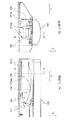
実施の形態1で説明した照明装置10は、図14に示す器具本体200の上面を天井面等の取付部に直付けする直付けタイプの照明装置である。
図14の器具本体200の短手方向の幅L(0)は、例えば、230mmである。また、照明装置10の傾斜部211dは、水平面から角度θ傾斜している。
The
The width L (0) in the short direction of the
(バリエーション1)
図33は、照明装置10−1の斜視図である。
図34は、図33のB−B断面図である。照明装置10−1は、直付けタイプである。照明装置10−1は、器具本体200−1の形状が器具本体200と異なる。照明装置10−1の短手方向の幅L(1)は照明装置10の短手方向の幅L(0)の0.6〜0.7倍である。照明装置10−1の短手方向の幅L(1)は、例えば、150mmである。照明装置10−1の傾斜部の水平面からの角度θは、図14の角度θよりも大きい。
(Variation 1)
FIG. 33 is a perspective view of the illumination device 10-1.
34 is a cross-sectional view taken along the line BB of FIG. The illumination device 10-1 is a direct attachment type. The lighting device 10-1 is different from the
(バリエーション2)
図35は、照明装置10−2の斜視図である。図36は図35のB−B断面図である。照明装置10−2は、直付けタイプである。照明装置10−2は、器具本体200−2の形状が照明装置10の器具本体1200と異なる。照明装置10−2は、器具本体200−2が光を反射させる構成を備えていないトラフタイプの照明器具である。
(Variation 2)
FIG. 35 is a perspective view of the illumination device 10-2. 36 is a cross-sectional view taken along the line BB of FIG. The illumination device 10-2 is a direct attachment type. The illumination device 10-2 is different from the fixture body 1200 of the
(バリエーション3)
図37は、照明装置10−3の斜視図である。図38は図37のB−B断面図である。照明装置10−3は、直付けタイプである。照明装置10−3は、器具本体200−3の形状が照明装置10の器具本体200と異なる。照明装置10−3は、器具本体200−3の傾斜部が凹部211の下方に向かって広がるように形成された反射笠タイプの照明器具である。
(Variation 3)
FIG. 37 is a perspective view of the lighting device 10-3. 38 is a cross-sectional view taken along line BB in FIG. The illumination device 10-3 is a direct attachment type. The illumination device 10-3 is different from the
(バリエーション4)
図39は、照明装置10−4の斜視図である。図40は、図39のB−B断面図である。照明装置10−4は、天井面等の取付部に形成された取付孔に埋め込まれて取り付けられる埋込タイプの照明器具である。照明装置10−4は、器具本体200−4の形状が照明装置10の器具本体200と異なる。照明装置10−4の短手方向の幅L(4)は、例えば150mmである。
(Variation 4)
FIG. 39 is a perspective view of the illumination device 10-4. 40 is a cross-sectional view taken along the line BB in FIG. The illuminating device 10-4 is an embedded type lighting fixture that is embedded and attached in an attachment hole formed in an attachment portion such as a ceiling surface. The illumination device 10-4 is different from the
(バリエーション5)
図41は、照明装置10−5の斜視図である。図42は、図41のB−B断面図である。照明装置10−5は、埋込タイプの照明器具である。照明装置10−5は、器具本体200−5の形状が照明装置10の器具本体200と異なる。照明装置10−5の短手方向の幅L(5)は、器具本体200−4の短手方向の幅L(4)の0.6〜0.7倍である。照明装置10−5の短手方向の幅L(5)は、例えば、100mmである。
(Variation 5)
FIG. 41 is a perspective view of the lighting device 10-5. 42 is a cross-sectional view taken along the line BB of FIG. The lighting device 10-5 is an embedded type lighting fixture. The illumination device 10-5 is different from the
(バリエーション6)
図43は、照明装置10−6の斜視図である。図44は、図43のB−B断面図である。照明装置10−6は、埋込タイプの照明器具である。照明装置10−6は、器具本体200−6の形状が照明装置10の器具本体200と異なる。照明装置10−6は、Cチャンネル回避型の照明器具である。照明装置10−6は、埋め込まれる器具本体200−6の高さH(6)が、図40に示す器具本体200−4の高さH(4)や図42に示す器具本体200−5の高さH(5)よりも低い。照明装置10−6の短手方向の幅L(6)は、照明装置10−5の短手方向の幅L(5)の1.8〜2.2倍である。照明装置10−6の短手方向の幅L(6)は、例えば、220mmである。
(Variation 6)
FIG. 43 is a perspective view of the lighting device 10-6. 44 is a cross-sectional view taken along the line BB of FIG. The lighting device 10-6 is an embedded type lighting fixture. The lighting device 10-6 is different from the fixture
上述したように、光源ユニット100と凹部211との取付構造は、実施の形態1で説明した取付構造と同一である。よって実施の形態1で説明した構成及び効果は実施の形態2の照明装置10−1〜300−6についても当てはまる。
なお、上述した光源ユニット、器具本体、および照明器具は、いずれも長手形状の例であるが、これ限らず、正方形、円形、多角形など他の形状であっても本願発明が適用できる。
As described above, the mounting structure between the
In addition, although the light source unit, the fixture body, and the lighting fixture described above are all examples of the longitudinal shape, the present invention is not limited to this and may be applied to other shapes such as a square, a circle, and a polygon.
10 照明装置、100 光源ユニット、110 プレート部、111 平面部、111a 基板取付面部、111b 電源取付面部、112 プレート側部、112a プレート係合部、120 発光素子基板、120a 発光素子、120b 基板、130 カバー、131 カバー側部、132 カバー前面部、133 カバー係合部、134 端部カバー、140 電源装置、150 連結具、1501 板部、151,151a 上端部、152 開口、152a 上辺部、152b 下辺部、152c 側辺部、152d,152e 傾斜辺部、152cd,152ce 接続辺部、153 取付部材、154 ねじ止め部、200 器具本体、210 本体部、201 開口部、211 凹部、211a 底面部、211b 側面部、211ba 開口縁部、211d 傾斜部、220 端板部、230 板ばね、231 固定部、232 円弧形状部、233 先端部、240 端子台、250 電源線挿入孔、251 ボルト挿入孔、2501 貫通孔、260 ユニット端部、300 取付部、400 吊ボルト、500 電線、500a 電源電線、500b 送り電線、500c 第1電線、500d ハーネス、500e 第2電線、501,502 コネクタ、701 中央部、702,703 矢印、9112 光源側嵌合部、9212 器具側嵌合部、9151 連結側嵌合部、9152a 縁、9152c 幅の両端、9010 引張機構部、9200 器具側取付部、9100 光源側取付部。 DESCRIPTION OF SYMBOLS 10 Illumination device, 100 Light source unit, 110 Plate part, 111 Plane part, 111a Substrate attachment surface part, 111b Power supply attachment part, 112 Plate side part, 112a Plate engaging part, 120 Light emitting element board, 120a Light emitting element, 120b board, 130 Cover, 131 Cover side part, 132 Cover front part, 133 Cover engaging part, 134 End cover, 140 Power supply unit, 150 Connector, 1501 Plate part, 151, 151a Upper end part, 152 Opening, 152a Upper side part, 152b Lower side Part, 152c side part, 152d, 152e inclined side part, 152cd, 152ce connecting side part, 153 mounting member, 154 screwing part, 200 instrument body, 210 body part, 201 opening part, 211 recess part, 211a bottom part, 211b Side part, 211ba opening Edge, 211d Inclined part, 220 End plate part, 230 Leaf spring, 231 Fixing part, 232 Arc-shaped part, 233 Tip part, 240 Terminal block, 250 Power line insertion hole, 251 Bolt insertion hole, 2501 Through hole, 260 unit End portion, 300 mounting portion, 400 suspension bolt, 500 electric wire, 500a power supply wire, 500b feed wire, 500c first electric wire, 500d harness, 500e second electric wire, 501,502 connector, 701 central portion, 702, 703 arrow, 9112 Light source side fitting part, 9212 Instrument side fitting part, 9151 Connection side fitting part, 9152a Edge, 9152c Width ends, 9010 Tensile mechanism part, 9200 Instrument side attaching part, 9100 Light source side attaching part.
Claims (10)
前記器具本体に配置された器具側取付部と連結された状態で弾性力によって前記器具本体の方向に引っ張られると共に、前記器具本体の短手方向に対する位置が決められる光源側取付部を備え、
前記器具側取付部は、板ばねであり、
前記光源側取付部は、前記板ばねが連結される連結具であり、
前記連結具は、
板状をなし、前記板ばねが挿入される開口が形成されると共に、前記器具本体に形成された器具側嵌合部に嵌められた状態で前記器具側嵌合部に拘束される連結側嵌合部を有する板部を備える光源ユニット。 In the light source unit attached to the longitudinally shaped instrument body,
The light source side mounting portion that is pulled in the direction of the device main body by an elastic force in a state of being connected to the device side mounting portion arranged in the device main body, and that determines the position of the device main body in the short direction ,
The appliance side mounting portion is a leaf spring,
The light source side mounting portion is a connector to which the leaf spring is connected,
The connector is
Connection side fitting which is plate-shaped and has an opening into which the leaf spring is inserted and which is constrained by the instrument side fitting part in a state of being fitted to the instrument side fitting part formed in the instrument body A light source unit including a plate portion having a joint portion .
前記器具本体に配置された器具側取付部と連結された状態で弾性力によって前記器具本体の方向に引っ張られると共に、前記器具本体に対する前記器具本体の長手方向まわりの取り付け角度が決められる光源側取付部を備え、
前記器具側取付部は、板ばねであり、
前記光源側取付部は、前記板ばねが連結される連結具であり、
前記連結具は、
板状をなし、前記板ばねが挿入される開口が形成されると共に、前記器具本体に形成された器具側嵌合部に嵌められた状態で前記器具側嵌合部に拘束される連結側嵌合部を有する板部を備える光源ユニット。 In the light source unit attached to the longitudinally shaped instrument body,
Light source side mounting in which the mounting angle around the longitudinal direction of the instrument body relative to the instrument body is determined while being pulled in the direction of the instrument body by an elastic force in a state of being connected to the instrument side mounting portion arranged in the instrument body with a part,
The appliance side mounting portion is a leaf spring,
The light source side mounting portion is a connector to which the leaf spring is connected,
The connector is
Connection side fitting which is plate-shaped and has an opening into which the leaf spring is inserted and which is constrained by the instrument side fitting part in a state of being fitted to the instrument side fitting part formed in the instrument body A light source unit including a plate portion having a joint portion .
前記弾性材料を用いて形成された前記器具側取付部と前記光源側取付部との少なくともいずれか一方の弾性力によって前記器具本体に取り付けられる請求項1または請求項2に記載の光源ユニット。 At least one of the appliance side mounting portion and the light source side mounting portion is formed using an elastic material,
The light source unit according to claim 1, wherein the light source unit is attached to the instrument main body by an elastic force of at least one of the instrument side attaching part and the light source side attaching part formed using the elastic material.
前記光源側取付部は、前記板ばねが連結される連結具であり、
前記連結具は、
板状をなし、前記板ばねが挿入される開口であって前記板ばねと当接する縁の幅の両端で前記板ばねが拘束される開口が形成された板部を有する請求項1から請求項3のいずれか一項に記載の光源ユニット。 The appliance side mounting portion is a leaf spring,
The light source side mounting portion is a connector to which the leaf spring is connected,
The connector is
2. The plate portion according to claim 1, wherein the plate portion has a plate shape and is formed with an opening into which the plate spring is inserted, and an opening in which the plate spring is constrained at both ends of a width of an edge contacting the plate spring. The light source unit according to claim 3.
前記器具本体に取り付けられる光源ユニットと、
弾性力によって前記光源ユニットを前記器具本体の方向に引っ張ると共に、前記器具本体の短手方向に対する前記光源ユニットの位置を決める引張機構部と
を備え、
前記引張機構部は、
前記器具本体に配置される板ばねと、
前記光源ユニットに配置され、前記板ばねが連結されることで前記光源ユニットを前記器具本体の方向に引っ張る連結具であって、板状をなし、前記板ばねが挿入される開口であり前記板ばねと当接する縁の幅の両端で前記板ばねが拘束される開口が形成された板部を有する連結具と
を備え、
前記器具本体は、
前記板ばねの一端が固定されて配置されると共に、前記板ばねの他端の動きが規制される板ばね規制部を備える照明装置。 A longitudinal instrument body;
A light source unit attached to the instrument body;
A tension mechanism that pulls the light source unit in the direction of the instrument body by an elastic force, and determines a position of the light source unit with respect to a short direction of the instrument body ,
The tension mechanism is
A leaf spring disposed in the instrument body;
A connector that is arranged in the light source unit and pulls the light source unit in the direction of the instrument body by being connected to the plate spring, and is a plate-like opening that is inserted into the plate spring. A connector having a plate portion in which openings for restraining the leaf spring are formed at both ends of the width of the edge contacting the spring;
With
The instrument body is
An illuminating device comprising: a leaf spring restricting portion that is disposed with one end of the leaf spring being fixed and that restricts movement of the other end of the leaf spring .
前記器具本体に取り付けられる光源ユニットと、
弾性力によって前記光源ユニットを前記器具本体の方向に引っ張ると共に、前記器具本体の短手方向に対する前記光源ユニットの位置を決める引張機構部と
を備え、
前記引張機構部は、
前記器具本体に配置される板ばねと、
前記光源ユニットに配置され、前記板ばねが連結されることで前記光源ユニットを前記器具本体の方向に引っ張る連結具であって、板状をなし、前記板ばねが挿入される開口であり前記板ばねと当接する縁の幅の両端で前記板ばねが拘束される開口が形成された板部を有する連結具と
を備え、
前記連結具は、
前記板部に、連結側嵌合部を有し、
前記引張機構部は、
前記器具本体に配置され、前記連結側嵌合部に嵌められた状態で前記連結側嵌合部を拘束している器具側嵌合部を有する照明装置。 A longitudinal instrument body;
A light source unit attached to the instrument body;
A tension mechanism that pulls the light source unit in the direction of the instrument body by an elastic force, and determines a position of the light source unit with respect to a short direction of the instrument body ,
The tension mechanism is
A leaf spring disposed in the instrument body;
A connector that is arranged in the light source unit and pulls the light source unit in the direction of the instrument body by being connected to the plate spring, and is a plate-like opening that is inserted into the plate spring. A connector having a plate portion in which openings for restraining the leaf spring are formed at both ends of the width of the edge contacting the spring;
With
The connector is
The plate portion has a coupling side fitting portion,
The tension mechanism is
An illuminating device having an appliance-side fitting portion that is disposed on the appliance main body and restrains the connection-side fitting portion in a state of being fitted to the connection-side fitting portion .
前記器具本体に取り付けられる光源ユニットと、
弾性力によって前記光源ユニットを前記器具本体の方向に引っ張ると共に、前記器具本体の短手方向に対する前記光源ユニットの位置を決める引張機構部と
を備え、
前記引張機構部は、
前記光源ユニットに配置される板ばねと、
前記器具本体に配置され、前記板ばねが連結されることで前記光源ユニットを前記器具本体の方向に引っ張る連結具であって、板状をなし、前記板ばねが挿入される開口であり前記板ばねと当接する縁の幅の両端で前記板ばねが拘束される開口が形成された板部を有する連結具と
を備え、
前記連結具は、
前記板部に、連結側嵌合部を有し、
前記引張機構部は、
前記光源ユニットに配置され、前記連結側嵌合部に嵌められた状態で前記連結側嵌合部を拘束している光源側嵌合部を有する照明装置。 A longitudinal instrument body;
A light source unit attached to the instrument body;
A tension mechanism that pulls the light source unit in the direction of the instrument body by an elastic force, and determines a position of the light source unit with respect to a short direction of the instrument body ,
The tension mechanism is
A leaf spring disposed in the light source unit;
A connector that is disposed on the instrument body and that pulls the light source unit in the direction of the instrument body when the leaf spring is coupled, has a plate shape, and is an opening into which the leaf spring is inserted. A connector having a plate portion in which openings for restraining the leaf spring are formed at both ends of the width of the edge contacting the spring;
With
The connector is
The plate portion has a coupling side fitting portion,
The tension mechanism is
An illumination device having a light source side fitting portion that is disposed in the light source unit and restrains the connection side fitting portion in a state of being fitted to the connection side fitting portion .
前記器具本体に取り付けられる光源ユニットと、
弾性力によって前記光源ユニットを前記器具本体の方向に引っ張ると共に、前記光源ユニットの前記器具本体の長手方向まわりの取り付け角度を決める引張機構部と
を備え、
前記引張機構部は、
前記器具本体に配置される板ばねと、
前記光源ユニットに配置され、前記板ばねが連結されることで前記光源ユニットを前記器具本体の方向に引っ張る連結具であって、板状をなし、前記板ばねが挿入される開口であり前記板ばねと当接する縁の幅の両端で前記板ばねが拘束される開口が形成された板部を有する連結具と
を備え、
前記器具本体は、
前記板ばねの一端が固定されて配置されると共に、前記板ばねの他端の動きが規制される板ばね規制部を備える照明装置。 A longitudinal instrument body;
A light source unit attached to the instrument body;
A tension mechanism that pulls the light source unit in the direction of the instrument body by an elastic force, and determines a mounting angle of the light source unit around the longitudinal direction of the instrument body ,
The tension mechanism is
A leaf spring disposed in the instrument body;
A connector that is arranged in the light source unit and pulls the light source unit in the direction of the instrument body by being connected to the plate spring, and is a plate-like opening that is inserted into the plate spring. A connector having a plate portion in which openings for restraining the leaf spring are formed at both ends of the width of the edge contacting the spring;
With
The instrument body is
An illuminating device comprising: a leaf spring restricting portion that is disposed with one end of the leaf spring being fixed and that restricts movement of the other end of the leaf spring .
前記器具本体に取り付けられる光源ユニットと、
弾性力によって前記光源ユニットを前記器具本体の方向に引っ張ると共に、前記光源ユニットの前記器具本体の長手方向まわりの取り付け角度を決める引張機構部と
を備え、
前記引張機構部は、
前記器具本体に配置される板ばねと、
前記光源ユニットに配置され、前記板ばねが連結されることで前記光源ユニットを前記器具本体の方向に引っ張る連結具であって、板状をなし、前記板ばねが挿入される開口であり前記板ばねと当接する縁の幅の両端で前記板ばねが拘束される開口が形成された板部を有する連結具と
を備え、
前記連結具は、
前記板部に、連結側嵌合部を有し、
前記引張機構部は、
前記器具本体に配置され、前記連結側嵌合部に嵌められた状態で前記連結側嵌合部を拘束している器具側嵌合部を有する照明装置。 A longitudinal instrument body;
A light source unit attached to the instrument body;
A tension mechanism that pulls the light source unit in the direction of the instrument body by an elastic force, and determines a mounting angle of the light source unit around the longitudinal direction of the instrument body ,
The tension mechanism is
A leaf spring disposed in the instrument body;
A connector that is arranged in the light source unit and pulls the light source unit in the direction of the instrument body by being connected to the plate spring, and is a plate-like opening that is inserted into the plate spring. A connector having a plate portion in which openings for restraining the leaf spring are formed at both ends of the width of the edge contacting the spring;
With
The connector is
The plate portion has a coupling side fitting portion,
The tension mechanism is
An illuminating device having an appliance-side fitting portion that is disposed on the appliance main body and restrains the connection-side fitting portion in a state of being fitted to the connection-side fitting portion .
前記器具本体に取り付けられる光源ユニットと、
弾性力によって前記光源ユニットを前記器具本体の方向に引っ張ると共に、前記光源ユニットの前記器具本体の長手方向まわりの取り付け角度を決める引張機構部と
を備えた、
前記引張機構部は、
前記光源ユニットに配置される板ばねと、
前記器具本体に配置され、前記板ばねが連結されることで前記光源ユニットを前記器具本体の方向に引っ張る連結具であって、板状をなし、前記板ばねが挿入される開口であり前記板ばねと当接する縁の幅の両端で前記板ばねが拘束される開口が形成された板部を有する連結具と
を備え、
前記連結具は、
前記板部に、連結側嵌合部を有し、
前記引張機構部は、
前記光源ユニットに配置され、前記連結側嵌合部に嵌められた状態で前記連結側嵌合部を拘束している光源側嵌合部を有する照明装置。 A longitudinal instrument body;
A light source unit attached to the instrument body;
A tension mechanism that pulls the light source unit in the direction of the instrument body by elastic force and determines an attachment angle of the light source unit around the longitudinal direction of the instrument body ;
The tension mechanism is
A leaf spring disposed in the light source unit;
A connector that is disposed on the instrument body and that pulls the light source unit in the direction of the instrument body when the leaf spring is coupled, has a plate shape, and is an opening into which the leaf spring is inserted. A connector having a plate portion in which openings for restraining the leaf spring are formed at both ends of the width of the edge contacting the spring;
With
The connector is
The plate portion has a coupling side fitting portion,
The tension mechanism is
An illumination device having a light source side fitting portion that is disposed in the light source unit and restrains the connection side fitting portion in a state of being fitted to the connection side fitting portion .
Priority Applications (1)
| Application Number | Priority Date | Filing Date | Title |
|---|---|---|---|
| JP2015121667A JP6564626B2 (en) | 2015-06-17 | 2015-06-17 | Light source unit and lighting device |
Applications Claiming Priority (1)
| Application Number | Priority Date | Filing Date | Title |
|---|---|---|---|
| JP2015121667A JP6564626B2 (en) | 2015-06-17 | 2015-06-17 | Light source unit and lighting device |
Related Child Applications (1)
| Application Number | Title | Priority Date | Filing Date |
|---|---|---|---|
| JP2019138419A Division JP6807996B2 (en) | 2019-07-29 | 2019-07-29 | Lighting device |
Publications (3)
| Publication Number | Publication Date |
|---|---|
| JP2017010626A JP2017010626A (en) | 2017-01-12 |
| JP2017010626A5 JP2017010626A5 (en) | 2018-06-21 |
| JP6564626B2 true JP6564626B2 (en) | 2019-08-21 |
Family
ID=57761742
Family Applications (1)
| Application Number | Title | Priority Date | Filing Date |
|---|---|---|---|
| JP2015121667A Active JP6564626B2 (en) | 2015-06-17 | 2015-06-17 | Light source unit and lighting device |
Country Status (1)
| Country | Link |
|---|---|
| JP (1) | JP6564626B2 (en) |
Families Citing this family (4)
| Publication number | Priority date | Publication date | Assignee | Title |
|---|---|---|---|---|
| JP6956556B2 (en) * | 2017-07-27 | 2021-11-02 | 三菱電機株式会社 | Mounting device and lighting device |
| JP6906391B2 (en) * | 2017-07-27 | 2021-07-21 | 三菱電機株式会社 | Mounting device and lighting device |
| JP7061850B2 (en) * | 2017-07-27 | 2022-05-02 | 三菱電機株式会社 | Mounting device and lighting device |
| JP7135370B2 (en) * | 2018-03-27 | 2022-09-13 | 三菱電機株式会社 | Connection unit and lighting device |
Family Cites Families (3)
| Publication number | Priority date | Publication date | Assignee | Title |
|---|---|---|---|---|
| JP6120366B2 (en) * | 2013-05-01 | 2017-04-26 | Necライティング株式会社 | Lighting equipment, light source parts and mounting parts |
| JP5507746B1 (en) * | 2013-08-02 | 2014-05-28 | アイリスオーヤマ株式会社 | LED lighting device |
| JP3195062U (en) * | 2014-10-14 | 2014-12-25 | Dnライティング株式会社 | lighting equipment |
-
2015
- 2015-06-17 JP JP2015121667A patent/JP6564626B2/en active Active
Also Published As
| Publication number | Publication date |
|---|---|
| JP2017010626A (en) | 2017-01-12 |
Similar Documents
| Publication | Publication Date | Title |
|---|---|---|
| JP6564626B2 (en) | Light source unit and lighting device | |
| JP6021010B2 (en) | lighting equipment | |
| JP6664152B2 (en) | Lighting equipment | |
| JP2019179776A (en) | Illuminating device | |
| JP6558953B2 (en) | Light source unit and lighting device | |
| JP6799937B2 (en) | lighting equipment | |
| JP7061850B2 (en) | Mounting device and lighting device | |
| WO2016175101A1 (en) | Illuminating device | |
| JP7281882B2 (en) | lighting equipment | |
| JP6956556B2 (en) | Mounting device and lighting device | |
| JP7149758B2 (en) | lighting equipment | |
| JP6906391B2 (en) | Mounting device and lighting device | |
| JP6179051B2 (en) | lighting equipment | |
| JP2019029132A (en) | Attachment device and lighting device | |
| JP7257753B2 (en) | lighting fixtures and lighting devices | |
| JP7135370B2 (en) | Connection unit and lighting device | |
| JP7278191B2 (en) | lighting equipment | |
| JP6611457B2 (en) | Lighting device | |
| JP6559533B2 (en) | Instrument body and lighting device | |
| JP2019175607A (en) | Fixing mechanism, fixing method, and illumination device | |
| JP6650747B2 (en) | Light source unit and lighting device | |
| JP6531932B2 (en) | lighting equipment | |
| JP2019106257A (en) | Lighting apparatus | |
| JP2017183125A (en) | Light source unit and lighting device | |
| JPWO2012120685A1 (en) | Connector holding structure |
Legal Events
| Date | Code | Title | Description |
|---|---|---|---|
| A521 | Request for written amendment filed |
Free format text: JAPANESE INTERMEDIATE CODE: A523 Effective date: 20180507 |
|
| A621 | Written request for application examination |
Free format text: JAPANESE INTERMEDIATE CODE: A621 Effective date: 20180507 |
|
| A131 | Notification of reasons for refusal |
Free format text: JAPANESE INTERMEDIATE CODE: A131 Effective date: 20190326 |
|
| A977 | Report on retrieval |
Free format text: JAPANESE INTERMEDIATE CODE: A971007 Effective date: 20190322 |
|
| A521 | Request for written amendment filed |
Free format text: JAPANESE INTERMEDIATE CODE: A523 Effective date: 20190425 |
|
| TRDD | Decision of grant or rejection written | ||
| A01 | Written decision to grant a patent or to grant a registration (utility model) |
Free format text: JAPANESE INTERMEDIATE CODE: A01 Effective date: 20190702 |
|
| A61 | First payment of annual fees (during grant procedure) |
Free format text: JAPANESE INTERMEDIATE CODE: A61 Effective date: 20190729 |
|
| R150 | Certificate of patent or registration of utility model |
Ref document number: 6564626 Country of ref document: JP Free format text: JAPANESE INTERMEDIATE CODE: R150 |
|
| R250 | Receipt of annual fees |
Free format text: JAPANESE INTERMEDIATE CODE: R250 |
|
| R250 | Receipt of annual fees |
Free format text: JAPANESE INTERMEDIATE CODE: R250 |