JP6564251B2 - Terminal cover - Google Patents
Terminal cover Download PDFInfo
- Publication number
- JP6564251B2 JP6564251B2 JP2015119657A JP2015119657A JP6564251B2 JP 6564251 B2 JP6564251 B2 JP 6564251B2 JP 2015119657 A JP2015119657 A JP 2015119657A JP 2015119657 A JP2015119657 A JP 2015119657A JP 6564251 B2 JP6564251 B2 JP 6564251B2
- Authority
- JP
- Japan
- Prior art keywords
- adherend
- base portion
- terminal
- electric wire
- terminal cover
- Prior art date
- Legal status (The legal status is an assumption and is not a legal conclusion. Google has not performed a legal analysis and makes no representation as to the accuracy of the status listed.)
- Active
Links
- 238000003780 insertion Methods 0.000 claims description 31
- 230000037431 insertion Effects 0.000 claims description 31
- 230000002093 peripheral effect Effects 0.000 claims description 26
- 239000013013 elastic material Substances 0.000 claims description 3
- 230000001464 adherent effect Effects 0.000 claims description 2
- XLYOFNOQVPJJNP-UHFFFAOYSA-N water Substances O XLYOFNOQVPJJNP-UHFFFAOYSA-N 0.000 description 5
- 230000035515 penetration Effects 0.000 description 3
- 239000011248 coating agent Substances 0.000 description 2
- 238000000576 coating method Methods 0.000 description 2
- 229920001971 elastomer Polymers 0.000 description 2
- 239000005060 rubber Substances 0.000 description 2
- 238000000034 method Methods 0.000 description 1
- 239000012466 permeate Substances 0.000 description 1
- 229920003051 synthetic elastomer Polymers 0.000 description 1
- 239000005061 synthetic rubber Substances 0.000 description 1
Images


Landscapes
- Connector Housings Or Holding Contact Members (AREA)
- Cable Accessories (AREA)
Description
本発明は、端末覆い体に係り、特に多芯ケーブルの端末部に装着される端末覆い体に関する。 The present invention relates to a terminal cover, and more particularly to a terminal cover that is attached to a terminal portion of a multicore cable.
従来から、電気自動車やハイブリッドカー等の車両に搭載されたバッテリを充電するために、充電コネクタが用いられている。この充電コネクタは、一対の半割体を重ね合せて組み付けることによってハウジングが形成される。ハウジング内には、複数の電線を一括して束ねて外被覆で覆った多芯ケーブルの端末部が収容され、この端末部から露出された複数の電線が接続する充電端子が所定位置に保持されている。 Conventionally, a charging connector has been used to charge a battery mounted on a vehicle such as an electric vehicle or a hybrid car. In this charging connector, a housing is formed by assembling a pair of halves so as to overlap each other. The housing accommodates a terminal portion of a multi-core cable in which a plurality of electric wires are bundled together and covered with an outer sheath, and a charging terminal to which the plurality of electric wires exposed from the terminal portion are connected is held at a predetermined position. ing.
ところで、この種の充電コネクタに雨水などの水が浸入した場合、浸入した水が各電線を伝って多芯ケーブルの外被覆内に浸入することが考えられる。このような多芯ケーブルへの水の浸入を防ぐため、例えばゴム製の電線覆い体をカップ状に形成し、電線覆い体の底部に形成された複数の電線挿通孔にそれぞれ多芯ケーブルの端末部から露出された電線を挿通させ、端末部の外被覆に電線覆い体を被せることにより、ゴム栓の内周面と外被覆とを密着させてシールするとともに、電線挿通孔に挿通された電線の外周面と電線挿通孔の内周面とを密着させてシールする端末部の防水構造が開示されている(特許文献1参照。)。 By the way, when water such as rainwater enters into this type of charging connector, it is conceivable that the infiltrated water enters the outer sheath of the multicore cable through each electric wire. In order to prevent water from entering such a multi-core cable, for example, a rubber wire cover is formed in a cup shape, and each end of the multi-core cable is inserted into a plurality of wire insertion holes formed in the bottom of the wire cover. By inserting the wire exposed from the part and covering the outer cover of the terminal part with the wire cover, the inner peripheral surface of the rubber plug and the outer cover are adhered and sealed, and the wire inserted through the wire insertion hole Has disclosed a waterproof structure for a terminal portion that tightly seals the outer peripheral surface of the wire and the inner peripheral surface of the wire insertion hole (see Patent Document 1).
しかしながら、特許文献1の端末覆い体は、軸方向の全長が長くなると、底部と反対側の開口から底部の電線挿通孔が見え難くなるため、開口から挿入された電線を電線挿通孔に通す作業が困難になる。しかも、電線挿通孔に通す電線の本数が多くなると、端末覆い体の内側に電線を挿入するスペースが狭くなるため、この傾向が顕著になる。 However, in the terminal cover body of Patent Document 1, when the entire length in the axial direction is increased, the wire insertion hole at the bottom is difficult to see from the opening opposite to the bottom, so that the wire inserted from the opening is passed through the wire insertion hole. Becomes difficult. In addition, when the number of electric wires passing through the electric wire insertion hole increases, the space for inserting the electric wires inside the terminal cover becomes narrow, and this tendency becomes remarkable.
本発明は、このような問題に鑑みてなされたものであり、電線挿通孔に電線を通す作業を容易化できる端末覆い体を提供することを課題とする。 This invention is made | formed in view of such a problem, and makes it a subject to provide the terminal cover which can facilitate the operation | work which lets an electric wire pass to an electric wire penetration hole.
上記課題を解決するため、本発明の端末覆い体は、円板状に形成された基部と、基部の周縁から延在してケーブルの端末部に被着される円筒状の被着部とを備え、基部と被着部は、弾性を有する材料で形成され、基部は、端末部から露出された電線が挿通される電線挿通孔が板厚方向に形成され、被着部は、基部の一端の周縁から他端に向けて折り曲げて延在され、被着部と基部の外周面との間に間隔を空けて、基部の外周を包囲してなる円環状の深溝部が形成され、被着部の内周面には、ケーブルの端末の外被覆を押し付ける複数の環状のリップが軸方向に間隔を空けて設けられてなることを特徴とする。 In order to solve the above problems, a terminal cover of the present invention includes a base portion formed in a disk shape and a cylindrical attachment portion that extends from the periphery of the base portion and is attached to the terminal portion of the cable. The base and the adherend are formed of an elastic material, the base is formed with a wire insertion hole through which the electric wire exposed from the terminal is inserted in the plate thickness direction, and the adherend is one end of the base An annular deep groove portion is formed which is bent and extended from the periphery of the base portion toward the other end and which surrounds the outer periphery of the base portion with a gap between the adherend portion and the outer peripheral surface of the base portion. A plurality of annular lips that press the outer sheath of the end of the cable are provided on the inner peripheral surface of the landing portion at intervals in the axial direction .
これによれば、端末覆い体は、基部を被着部の内側に押し込むことにより、深溝部が起点となって、基部の深溝部に囲まれた内面を軸方向の被着部の外側に移動させ、端末覆い体を容易に裏返すことができる。このように裏返された端末覆い体は、電線挿通孔が形成された基部の内面が被着部に囲まれることなく、外側に露出された状態となるため、電線挿通孔に電線を通す作業が容易になる。 According to this, the terminal cover moves the inner surface surrounded by the deep groove portion of the base portion to the outside of the axial adherend portion by pushing the base portion into the inside of the adherend portion. The terminal cover can be easily turned over. Since the terminal cover body turned over in this way is exposed to the outside without the inner surface of the base portion where the wire insertion hole is formed surrounded by the adherend, the work of passing the electric wire through the wire insertion hole It becomes easy.
この場合において、被着部には、基部と反対側の端面から軸方向に延びる切欠き部が形成されていることが好ましい。これによれば、切欠き部を介して被着部を簡単に外側に折り返すことができるため、基部を被着部の内側に押し込みながら、被着部を折り返すことにより、端末覆い体を裏返す作業がより簡単になる。なお、切り欠き部は、被着部の中心軸に対して互いに反対側の位置にそれぞれ形成されていることが好ましい。 In this case, it is preferable that a notch portion extending in the axial direction from the end surface opposite to the base portion is formed in the adherent portion. According to this, since the adherend part can be easily folded outward through the notch part, the terminal cover is turned over by folding the adherend part while pushing the base part inside the adherend part. Becomes easier. In addition, it is preferable that the notch part is each formed in the position on the opposite side mutually with respect to the central axis of a to-be-adhered part.
また、深溝部に対応する基部の外径は、ケーブルの端末に被着される部分の被着部の内径寸法よりも小さい内径寸法を有して形成されることが好ましい。これによれば、深溝部に囲まれた基部の内面を軸方向に移動させるときに、基部の内面が被着部の内周面と接触することがないから、端末覆い体を裏返す作業がより簡単になる。 Moreover, it is preferable that the outer diameter of the base part corresponding to the deep groove part is formed to have an inner diameter dimension smaller than the inner diameter dimension of the attaching part of the part attached to the end of the cable . According to this, when the inner surface of the base portion surrounded by the deep groove portion is moved in the axial direction, the inner surface of the base portion does not come into contact with the inner peripheral surface of the adherend portion. It will be easy.
本発明によれば、電線挿通孔に電線を通す作業を容易化できる端末覆い体を提供することができる。 ADVANTAGE OF THE INVENTION According to this invention, the terminal cover body which can facilitate the operation | work which lets an electric wire pass to an electric wire penetration hole can be provided.
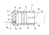
以下、本発明が適用される端末覆い体の一実施形態について図面を参照して説明する。図1は、端末覆い体の外観斜視図であり、図2は、端末覆い体の断面図である。本実施形態では、端末覆い体11を多芯ケーブルW1の端末部に装着して使用する例を説明するが、本発明が適用される端末覆い体11は、この例に限られず、1本の電線を収容した単芯ケーブルの端末部に装着して使用することもできる。
Hereinafter, an embodiment of a terminal cover to which the present invention is applied will be described with reference to the drawings. FIG. 1 is an external perspective view of the terminal cover, and FIG. 2 is a cross-sectional view of the terminal cover. In the present embodiment, an example in which the
端末覆い体11が被着される多芯ケーブルW1は、複数の電線W2を一括して束ねて外被覆で覆って構成され、端末部から露出された複数の電線W2が、端末覆い体11から外部に引き出されている。
The multi-core cable W1 to which the
本実施形態の端末覆い体11は、弾性を有する材料(例えば、合成ゴム)でカップ状に形成され、図1及び図2に示すように、円板状に形成された基部13と、基部13の周縁から軸方向に延在して多芯ケーブルW1の端末部に被着される円筒状の被着部15とを有している。以下では、図2の左側(基部13に対して被着部15と反対方向)を前方とし、図2の右側(基部13に対して被着部15が延びる方向)を後方として説明する。
The
基部13は、多芯ケーブルW1の端末部から露出された複数の電線W2がそれぞれ挿通される複数の電線挿通孔17を有している。各電線挿通孔17には、図2に示すように、電線挿通孔17に挿通された電線W2の外周面を押し付ける複数の環状のリップ19が、軸方向に所定の間隔で設けられている。各電線挿通孔17は、これらのすべてが同じ内径に設定されるものではないが、それぞれ、挿通される電線W2の外径に応じて内径寸法が設定される。基部13の被着部15と反対側の端面21は、外周側の角部が面取りされている。
The
被着部15は、図2に示すように、基部13の厚みよりも薄い肉厚で円筒状に形成され、基部13と反対側の後端部に、開口部23が形成される。被着部15の外周面は、基部13の外周面に向かって拡径する傾斜部25を有している。被着部15の傾斜部25よりも後方の内周面には、多芯ケーブルW1の外被覆を押し付ける複数の環状のリップ27が、軸方向に所定の間隔で設けられている。
As shown in FIG. 2, the
ところで、このように構成された端末覆い体11を多芯ケーブルW1の端末部に装着するには、端末部から露出された複数の電線W1を1本ずつ開口部23から端末覆い体11の内部に挿入し、この挿入された電線W1の先端部を対応する電線挿通孔17に挿入することになる。しかし、この方法の場合、例えば、被着部15の全長が長くなると、開口部23から電線挿通孔17の位置が視認し難くなるため、組付け作業が困難になる虞がある。
By the way, in order to attach the
この点、本実施形態の端末覆い体11では、図2に示すように、基部13の端面21と反対側の内面29に、円環状の深溝31が形成されている。この深溝31は、被着部15の内面の延長線が基部13と交わる部位に沿って形成され、具体的には、被着部15の内周面に沿って形成されている。深溝31の深さは、基部13の厚みの半分以上に設定されている。各電線挿通孔17は、いずれも、深溝31の内側の内面29に位置するようになっている。
In this regard, in the
深溝31に包囲された内側の基部13aは、円板状に形成され、その外径寸法(深溝31の内径寸法)が、被着部15の内径寸法よりも小さく設定され、さらには、リップ27の内径寸法よりも小さく設定されている。
The
また、本実施形態の被着部15は、開口部23の周縁の外周面から周方向に亘って膨出する環状の膨出部33と、その後端から軸方向の前方に延びる一対の切欠き部35,35とを有している。一対の切欠き部35,35は、被着部15の中心軸に対して互いに反対側に設けられる。
Further, the
このようにして構成された端末覆い体11は、従来のように開口部23から被着部15の内側に挿入した電線W2を電線挿通孔17に通すのではなく、図1の端末覆い体11の表裏を裏返して、表側に露出された電線挿通孔17に電線W2を通すことを特徴としている。以下、端末覆い体11を裏返す作業を作用とともに説明する。
The
まず、端末覆い体11は、図1において、被着部15の外周面を押さえた状態で、基部13の端面21を被着部15の内側に向けて軸方向に押し付ける。このとき、内側に押し付けられた基部13は、深溝31が起点となって、被着部15の内側を(比較的弱い力で)後方へ移動する。図3は、このようにして基部13が被着部15の内側に移動する途中の状態を前方からみた図であり、図4は、図3を後方からみた図である。
First, in FIG. 1, the
被着部15の内側を移動する基部13aは、その外径寸法がリップ27の内径寸法よりも小さく設定されているため、移動の途中でリップ27と接触することがなく、スムーズに移動する。
Since the outer diameter dimension of the
さらに基部13aを押し付けると、基部13aが被着部15の開口部23を通過して、最終的には、図5及び図6に示すように、端末覆い体11が完全に裏返された状態となる。この裏返された端末覆い体11は、基部13aの内面29が、被着部15に囲まれることなく、基部13aとともに外側に露出された状態となる。なお、露出された基部13aは、深溝31の溝底に相当する面に対して外側へ円板状に突出する格好となる。
When the
これにより、多芯ケーブルW1から露出された複数の電線W2は、それぞれ、外部に露出された基部13aの電線挿通孔17に、図5の矢印Pの方向から電線W2を挿入することができる。したがって、電線挿通孔17の位置を確実に視認することができ、しかも、電線挿通孔17が被着部15に囲まれることなく完全に開放された状態となるため、電線W2の本数に関わらず、電線W2を電線挿通孔17に通す作業が容易になり、作業性を高めることができる。
Thereby, the plurality of electric wires W2 exposed from the multicore cable W1 can be inserted into the electric wire insertion holes 17 of the
また、本実施形態の被着部15は、後端部の膨出部33と、一対の切欠き部35,35がそれぞれ形成されているため、端末覆い体11を裏返すときには、膨出部33を摘まんで、被着部15を外側へ折り返すことで、一対の切欠き部35,35を介して周方向に2分割された被着部15を容易に裏返すことができる。したがって、基部13の端面21を被着部15の内側へ押し付けるとともに、被着部15を外側へ折り返す操作を同時に行うことで、端末覆い体11をより簡単に裏返すことができる。
Further, since the
そして、すべての電線W2が電線挿通孔17に挿通された後は、端末覆い体11を各電線W2に沿って移動させ、基部13の内面29を多芯ケーブルW1の端末部に押し付ける。続いて、端末覆い体11は、裏返された被着部15を元の状態に戻すべく、被着部15の膨出部33を摘まんで、被着部15を多芯ケーブルW1の端末部に被せるように、矢印Sの方向に引き戻す。この場合も、被着部15は、一対の切欠き部35,35を介して2分割されるため、被着部を元の状態に戻す作業を容易に行うことができる。
And after all the electric wires W2 were inserted in the electric
このようして多芯ケーブルW1の端末部に端末覆い体11が被着されると、図1に示すように、多芯ケーブルW1の外被覆は、端末覆い体11の被着部15のリップ27に押し付けられて、被着部15と外被覆との隙間が水密にシールされる。また、電線挿通孔17に通された各電線W2は、図1に示すように、電線挿通孔17のリップ19に外周面(電線の被覆面)が押し付けられて、電線W2の外周面と電線挿通孔17の内周面との隙間が水密にシールされる。これにより、端末覆い体11が装着された多芯ケーブルW1の端末部に水が浸入するのを防ぐことができる。
Thus, when the
本実施形態によれば、端末覆い体11を容易に裏返すことができるため、その後の電線挿通孔17に電線W2を挿通させる作業が容易になり、これらの一連の作業を効率よく行うことができる。
According to this embodiment, since the
また、本実施形態によれば、基部13の厚みを大きく設定しても、深溝31を形成することで、端末覆い体11を容易に裏返すことができる。これにより、電線挿通孔17の長さを確保することができるから、電線W2の外周面と電線挿通孔17の内周面との隙間の防水性を高めることができる。
Moreover, according to this embodiment, even if the thickness of the
本実施形態にように、端末覆い体11が被着された多芯ケーブルW1は、例えば、電気自動車やハイブリッドカー等の車両に搭載されたバッテリを充電するための充電コネクタ等に収容することで、多芯ケーブルW1の外被覆に水が浸入するのを防ぐことができ、コネクタの信頼性を高めることができる。
As in the present embodiment, the multi-core cable W1 to which the
以上、本発明の実施形態を図面により詳述したが、本実施形態は本発明の例示にしか過ぎないものであり、請求項に記載された範囲内において変更・変形することが可能である。 The embodiment of the present invention has been described in detail with reference to the drawings. However, the present embodiment is merely an example of the present invention, and can be changed or modified within the scope of the claims.
例えば、本実施形態では、端末覆い体11の深溝31を被着部15の内周面に沿って形成する例を説明したが、深溝31は、すべての電線挿通孔17を包囲するように配置されていれば、被着部15の内周面からある程度離れて配置されていてもよい。
For example, in this embodiment, although the example which forms the
11 端末覆い体
13 基部
15 被着部
17 電線挿通孔
19,27 リップ
31 深溝
33 膨出部
35 切欠き部
W1 多芯ケーブル
W2 電線
DESCRIPTION OF
Claims (3)
前記基部と前記被着部は、弾性を有する材料で形成され、
前記基部は、前記端末部から露出された電線が挿通される電線挿通孔が板厚方向に形成され、
前記被着部は、前記基部の一端の周縁から他端に向けて折り曲げて延在され、
前記被着部と前記基部の外周面との間に間隔を空けて、前記基部の外周を包囲してなる円環状の深溝部が形成され、
前記被着部の内周面には、前記ケーブルの端末の外被覆を押し付ける複数の環状のリップが軸方向に間隔を空けて設けられてなる端末覆い体。 A base portion formed in a disc shape, and a cylindrical adherent portion that extends from the periphery of the base portion and adheres to the end portion of the cable,
The base and the adherend are formed of an elastic material,
In the base portion, an electric wire insertion hole into which an electric wire exposed from the terminal portion is inserted is formed in the plate thickness direction,
The adherend portion is bent and extended from the periphery of one end of the base portion toward the other end,
An annular deep groove portion is formed that surrounds the outer periphery of the base portion with a space between the adherend portion and the outer peripheral surface of the base portion ,
A terminal covering body in which a plurality of annular lips that press the outer covering of the terminal of the cable are provided on the inner peripheral surface of the adherend portion at intervals in the axial direction .
Priority Applications (1)
| Application Number | Priority Date | Filing Date | Title |
|---|---|---|---|
| JP2015119657A JP6564251B2 (en) | 2015-06-12 | 2015-06-12 | Terminal cover |
Applications Claiming Priority (1)
| Application Number | Priority Date | Filing Date | Title |
|---|---|---|---|
| JP2015119657A JP6564251B2 (en) | 2015-06-12 | 2015-06-12 | Terminal cover |
Publications (2)
| Publication Number | Publication Date |
|---|---|
| JP2017005923A JP2017005923A (en) | 2017-01-05 |
| JP6564251B2 true JP6564251B2 (en) | 2019-08-21 |
Family
ID=57752025
Family Applications (1)
| Application Number | Title | Priority Date | Filing Date |
|---|---|---|---|
| JP2015119657A Active JP6564251B2 (en) | 2015-06-12 | 2015-06-12 | Terminal cover |
Country Status (1)
| Country | Link |
|---|---|
| JP (1) | JP6564251B2 (en) |
Families Citing this family (1)
| Publication number | Priority date | Publication date | Assignee | Title |
|---|---|---|---|---|
| KR102522216B1 (en) | 2020-09-04 | 2023-04-18 | 율촌화학 주식회사 | Primer layer composition, secondary battery pouch film using the same, and method for manufacturing the same |
Family Cites Families (3)
| Publication number | Priority date | Publication date | Assignee | Title |
|---|---|---|---|---|
| JPS59170975U (en) * | 1983-04-30 | 1984-11-15 | 住友電装株式会社 | Waterproof boots for connector housing |
| JP2002369364A (en) * | 2001-06-12 | 2002-12-20 | Mitsubishi Cable Ind Ltd | Branch cover for cable |
| JP2003143745A (en) * | 2001-10-31 | 2003-05-16 | Kowa Kogyo Kk | Electric wire terminal cover |
-
2015
- 2015-06-12 JP JP2015119657A patent/JP6564251B2/en active Active
Also Published As
| Publication number | Publication date |
|---|---|
| JP2017005923A (en) | 2017-01-05 |
Similar Documents
| Publication | Publication Date | Title |
|---|---|---|
| JP5751875B2 (en) | Shield connector | |
| JP5757219B2 (en) | Seal member | |
| JP6234034B2 (en) | Shield connector structure | |
| US9842671B2 (en) | Seal member and seal structure for multicore cable | |
| CN107801423B (en) | Sealing structure of multi-core cable | |
| JP5965751B2 (en) | Connector terminal and water stop method for connector terminal | |
| JP5582413B2 (en) | Cable with connector | |
| JP2016012422A (en) | connector | |
| JP2018133278A (en) | Charging inlet | |
| WO2013002370A1 (en) | Terminal structure of braided wire, and terminal treatment method for braided wire | |
| JP2008204960A (en) | Waterproof connector | |
| JP6564251B2 (en) | Terminal cover | |
| US9203225B2 (en) | Wire fixing member | |
| JP6553872B2 (en) | Rubber stopper for waterproof connector and waterproof connector | |
| JP5751180B2 (en) | Rubber stopper | |
| JP5440437B2 (en) | Electric wire terminal structure | |
| JP2015207439A (en) | Waterproof rubber stopper, wire with waterproof rubber stopper, and connector with wire | |
| JP5913194B2 (en) | connector | |
| JP5705429B2 (en) | Waterproof terminal structure | |
| JP2019091611A (en) | Connection structure of single core wire | |
| JP2019220248A (en) | Waterproof structure for multicore wire | |
| JP2016095915A (en) | Rubber stopper | |
| JP2009048928A (en) | Rubber plug, and waterproof connector | |
| JP2014089913A (en) | Protective cover | |
| WO2016208420A1 (en) | Connector |
Legal Events
| Date | Code | Title | Description |
|---|---|---|---|
| A621 | Written request for application examination |
Free format text: JAPANESE INTERMEDIATE CODE: A621 Effective date: 20180517 |
|
| A131 | Notification of reasons for refusal |
Free format text: JAPANESE INTERMEDIATE CODE: A131 Effective date: 20181120 |
|
| A521 | Request for written amendment filed |
Free format text: JAPANESE INTERMEDIATE CODE: A523 Effective date: 20190117 |
|
| A02 | Decision of refusal |
Free format text: JAPANESE INTERMEDIATE CODE: A02 Effective date: 20190416 |
|
| A521 | Request for written amendment filed |
Free format text: JAPANESE INTERMEDIATE CODE: A523 Effective date: 20190603 |
|
| A911 | Transfer to examiner for re-examination before appeal (zenchi) |
Free format text: JAPANESE INTERMEDIATE CODE: A911 Effective date: 20190612 |
|
| TRDD | Decision of grant or rejection written | ||
| A01 | Written decision to grant a patent or to grant a registration (utility model) |
Free format text: JAPANESE INTERMEDIATE CODE: A01 Effective date: 20190702 |
|
| A61 | First payment of annual fees (during grant procedure) |
Free format text: JAPANESE INTERMEDIATE CODE: A61 Effective date: 20190726 |
|
| R150 | Certificate of patent or registration of utility model |
Ref document number: 6564251 Country of ref document: JP Free format text: JAPANESE INTERMEDIATE CODE: R150 |
|
| R250 | Receipt of annual fees |
Free format text: JAPANESE INTERMEDIATE CODE: R250 |
|
| S531 | Written request for registration of change of domicile |
Free format text: JAPANESE INTERMEDIATE CODE: R313531 |
|
| R350 | Written notification of registration of transfer |
Free format text: JAPANESE INTERMEDIATE CODE: R350 |
|
| R250 | Receipt of annual fees |
Free format text: JAPANESE INTERMEDIATE CODE: R250 |
|
| R250 | Receipt of annual fees |
Free format text: JAPANESE INTERMEDIATE CODE: R250 |