JP6563439B2 - Semantic naming model - Google Patents
Semantic naming model Download PDFInfo
- Publication number
- JP6563439B2 JP6563439B2 JP2017092541A JP2017092541A JP6563439B2 JP 6563439 B2 JP6563439 B2 JP 6563439B2 JP 2017092541 A JP2017092541 A JP 2017092541A JP 2017092541 A JP2017092541 A JP 2017092541A JP 6563439 B2 JP6563439 B2 JP 6563439B2
- Authority
- JP
- Japan
- Prior art keywords
- attribute
- sensor data
- data
- query
- location
- Prior art date
- Legal status (The legal status is an assumption and is not a legal conclusion. Google has not performed a legal analysis and makes no representation as to the accuracy of the status listed.)
- Expired - Fee Related
Links
Images


Classifications
-
- H—ELECTRICITY
- H04—ELECTRIC COMMUNICATION TECHNIQUE
- H04L—TRANSMISSION OF DIGITAL INFORMATION, e.g. TELEGRAPHIC COMMUNICATION
- H04L67/00—Network arrangements or protocols for supporting network services or applications
- H04L67/01—Protocols
- H04L67/12—Protocols specially adapted for proprietary or special-purpose networking environments, e.g. medical networks, sensor networks, networks in vehicles or remote metering networks
-
- H—ELECTRICITY
- H04—ELECTRIC COMMUNICATION TECHNIQUE
- H04W—WIRELESS COMMUNICATION NETWORKS
- H04W4/00—Services specially adapted for wireless communication networks; Facilities therefor
- H04W4/30—Services specially adapted for particular environments, situations or purposes
- H04W4/38—Services specially adapted for particular environments, situations or purposes for collecting sensor information
-
- H—ELECTRICITY
- H04—ELECTRIC COMMUNICATION TECHNIQUE
- H04W—WIRELESS COMMUNICATION NETWORKS
- H04W4/00—Services specially adapted for wireless communication networks; Facilities therefor
- H04W4/70—Services for machine-to-machine communication [M2M] or machine type communication [MTC]
Description
(関連出願の引用)
本願は、米国仮特許出願第61/823,976号(2013年5月16日出願、名称「SEMANTIC MODEL AND NAMING FOR INTERNET OF THINGS SENSORY DATA」)の利益を主張し、上記出願の内容は、参照により本明細書に引用される。
(Citation of related application)
This application claims the benefit of US Provisional Patent Application No. 61 / 823,976 (filed on May 16, 2013, name “SEMANTIC MODEL AND NAMING FOR INTERNET OF THINGS SENSORY DATA”). Is incorporated herein by reference.
物理的環境で展開されるネットワーク使用可能デバイスおよびセンサの数の急速な増加が、通信ネットワークを変化させている。次の10年以内に、何十億ものデバイスが、スマートグリッド、スマートホーム、e−ヘルス、自動車、輸送、物流、および環境監視等の種々の分野で、多くの用途およびサービスプロバイダによるサービスのための無数の実環境データを生成するであろうと予測される。現在の情報ネットワーキング技術への実環境データおよびサービスの統合を可能にする関連技術および解決策は、多くの場合、モノのインターネット(IoT)の総称の下で説明される。デバイスによって作成される大量のデータにより、このデータを識別し、問い合わせる効率的な方法の必要性がある。 The rapid increase in the number of network-enabled devices and sensors deployed in the physical environment is changing communications networks. Within the next decade, billions of devices will be served by many applications and service providers in various fields such as smart grids, smart homes, e-health, automotive, transportation, logistics, and environmental monitoring. Is expected to generate a myriad of real-world data. Related technologies and solutions that enable the integration of real-world data and services into current information networking technologies are often described under the generic name of the Internet of Things (IoT). Due to the large amount of data created by the device, there is a need for an efficient way to identify and query this data.
データの他の記述メタデータへの連携を提供しながら、データの主要な属性(時間、場所、タイプ、および値)を捕捉するデータのために、意味モデルが提示される。データ名公開、データ集計、およびデータクエリのためのプロシージャも説明される。 A semantic model is presented for data that captures the key attributes (time, location, type, and value) of the data while providing linkage to other descriptive metadata of the data. Procedures for data name publication, data aggregation, and data queries are also described.
本概要は、発明を実施するための形態において以下でさらに説明される、簡略化形態の概念の選択を導入するように提供される。本概要は、請求された主題の主要な特徴または不可欠な特徴を識別することを目的としておらず、また、請求された主題の範囲を限定するために使用されることも目的としていない。さらに、請求された主題は、本開示の任意の部分で記述されるいずれかまたは全ての不利点を解決する制限に限定されない。
本発明はさらに、例えば、以下を提供する。
(項目1)
プロセッサと、
前記プロセッサと連結されたメモリと
を備え、
前記メモリは、実行可能命令を備え、前記実行可能命令は、前記プロセッサによって実行されると、
第1の時間属性、第1の場所属性、および第1のタイプ属性を含む第1の属性を伴う第1の感覚データを受信することと、
前記第1の時間属性、前記第1の場所属性、および前記第1のタイプ属性に基づいて、前記感覚データのための第1の名前を作成することと
を含む動作を前記プロセッサに達成させる、デバイス。
(項目2)
前記実行可能命令は、前記第1の名前をサーバに対して公開することを含むさらなる動作を前記プロセッサに達成させ、前記サーバは、前記第1の名前を記憶することにより、前記第1の時間属性、前記第1の場所属性、または前記第1のタイプ属性に基づいて、クエリが前記感覚データについて行われることを可能にする、項目1に記載のデバイス。
(項目3)
前記実行可能命令は、
前記第1の感覚データを第2の感覚データと集計することであって、前記第2の感覚データは、第2の時間属性、第2の場所属性、または第2のタイプ属性を含む第2の属性を有する、ことと、
前記第1の名前を、前記集計された第1の感覚データおよび第2の感覚データに割り当てることと
を含むさらなる動作を前記プロセッサに達成させる、項目1に記載のデバイス。
(項目4)
前記実行可能命令は、ディスプレイ上で前記第1の名前を表示するための命令を提供することを含むさらなる動作を前記プロセッサに達成させる、項目1に記載のデバイス。
(項目5)
前記第1の場所属性は、ジオハッシュタグを含む、項目1に記載のデバイス。
(項目6)
前記第1の名前は、前記第1のタイプのメッセージダイジェストを含む、項目1に記載のデバイス。
(項目7)
前記第1の名前は、前記第1の時間属性のメッセージダイジェストを含む、項目1に記載のデバイス。
(項目8)
前記デバイスは、センサを備えている、項目1に記載のデバイス。
(項目9)
前記第1の名前は、前記デバイスのデバイス識別子を含む、項目1に記載のデバイス。(項目10)
コンピュータ実行可能命令を備えているコンピュータ読み取り可能な記憶媒体であって、
前記命令は、コンピュータデバイスによって実行されると、
第1の時間属性、第1の場所属性、および第1のタイプ属性を含む第1の属性を伴う第1の感覚データを受信することと、
前記第1の時間属性、前記第1の場所属性、および前記第1のタイプ属性に基づいて、前記感覚データのための第1の名前を作成することと
を含む命令を前記コンピュータデバイスに行わせる、コンピュータ読み取り可能な記憶媒体。
(項目11)
さらなる命令が、前記第1の名前をサーバに対して公開することを含み、前記サーバは、前記第1の名前を記憶することにより、前記第1の時間属性、前記第1の場所属性、または前記第1のタイプ属性に基づいて、クエリが前記感覚データについて行われることを可能にする、項目10に記載のコンピュータ読み取り可能な記憶媒体。
(項目12)
さらなる命令が、
前記第1の感覚データを第2の感覚データと集計することであって、前記第2の感覚データは、第2の時間属性、第2の場所属性、または第2のタイプ属性を含む第2の属性を有する、ことと、
前記第1の名前を、前記集計された第1の感覚データおよび第2の感覚データに割り当てることと
を含む、項目10に記載のコンピュータ読み取り可能な記憶媒体。
(項目13)
さらなる命令が、前記第1の名前を表示するための命令を提供することを含む、項目10に記載のコンピュータ読み取り可能な記憶媒体。
(項目14)
前記第1の場所属性は、ジオハッシュタグを含む、項目10に記載のコンピュータ読み取り可能な記憶媒体。
(項目15)
前記第1の名前は、前記第1のタイプのメッセージダイジェストを含む、項目10に記載のコンピュータ読み取り可能な記憶媒体。
(項目16)
前記第1の名前は、前記第1の時間属性のメッセージダイジェストを含む、項目10に記載のコンピュータ読み取り可能な記憶媒体。
(項目17)
前記コンピュータデバイスは、センサを備えている、項目10に記載のコンピュータ読み取り可能な記憶媒体。
(項目18)
前記第1の名前は、前記デバイスのデバイス識別子を含む、請求香10に記載のコンピュータ読み取り可能な記憶媒体。
(項目19)
センサによって、値を伴う感覚データを観察することであって、前記値を伴う前記感覚データは、時間属性、場所属性、およびタイプ属性を含む属性を有する、ことと、
前記センサによって、前記時間属性、前記場所属性、および前記値属性に基づいて、前記感覚データの名前を作成することと、
前記センサによって、前記名前をサーバに対して公開することと
を含む、方法。
(項目20)
前記サーバは、前記感覚データに対するクエリを受信し、前記クエリは、前記時間属性、前記場所属性、前記値属性、またはタイプ属性を含む、請求香19に記載の方法。
This summary is provided to introduce a selection of concepts in a simplified form that are further described below in the detailed description. This summary is not intended to identify key features or essential features of the claimed subject matter, nor is it intended to be used to limit the scope of the claimed subject matter. Furthermore, the claimed subject matter is not limited to limitations that solve any or all disadvantages noted in any part of this disclosure.
The present invention further provides, for example:
(Item 1)
A processor;
A memory coupled to the processor,
The memory comprises executable instructions, and the executable instructions are executed by the processor;
Receiving first sensory data with a first attribute including a first time attribute, a first location attribute, and a first type attribute;
Causing the processor to perform an action comprising: creating a first name for the sensory data based on the first time attribute, the first location attribute, and the first type attribute; device.
(Item 2)
The executable instructions cause the processor to perform further actions including exposing the first name to a server, and the server stores the first name to store the first time. 2. The device of
(Item 3)
The executable instruction is:
The first sensory data is aggregated with the second sensory data, and the second sensory data includes a second time attribute, a second location attribute, or a second type attribute. Having the attribute of
The device of
(Item 4)
The device of
(Item 5)
The device of
(Item 6)
The device of
(Item 7)
The device of
(Item 8)
The device of
(Item 9)
The device of
A computer readable storage medium comprising computer executable instructions,
When the instructions are executed by a computing device,
Receiving first sensory data with a first attribute including a first time attribute, a first location attribute, and a first type attribute;
Causing the computing device to perform instructions comprising: creating a first name for the sensory data based on the first time attribute, the first location attribute, and the first type attribute A computer-readable storage medium.
(Item 11)
Further instructions include publishing the first name to a server, the server storing the first name to thereby store the first time attribute, the first location attribute, or Item 11. The computer readable storage medium of
(Item 12)
Further instructions
The first sensory data is aggregated with the second sensory data, and the second sensory data includes a second time attribute, a second location attribute, or a second type attribute. Having the attribute of
The computer-readable storage medium according to
(Item 13)
The computer-readable storage medium of
(Item 14)
Item 11. The computer readable storage medium of
(Item 15)
Item 11. The computer readable storage medium of
(Item 16)
Item 11. The computer readable storage medium of
(Item 17)
Item 11. The computer readable storage medium of
(Item 18)
The computer-readable storage medium according to
(Item 19)
Observing sensory data with a value by a sensor, wherein the sensory data with the value has attributes including a time attribute, a location attribute, and a type attribute;
Creating a name for the sensory data by the sensor based on the time attribute, the location attribute, and the value attribute;
Publishing the name to a server by the sensor.
(Item 20)
The method according to claim 19, wherein the server receives a query for the sensory data, the query including the time attribute, the location attribute, the value attribute, or a type attribute.
添付の図面と併せて一例として挙げられる、以下の説明から、より詳細に理解され得る。
ネットワーク使用可能センサデバイスは、物理的環境から収集される観察および測定データを捕捉して通信することを可能にする。本明細書で議論される場合、センサは、物理的性質を検出または測定し、記録し、示し、またはそれに応答する、デバイスとして定義され得る。例えば、センサは、光、運動、温度、磁場、重力、湿度、湿気、振動、圧力、電場、音、および環境の他の側面を検出し得る。感覚データは、データを有意義にすることに役立つように、環境または測定データの観察、ならびに時間、場所、および他の記述属性を含み得る。例えば、15度の温度値は、空間(例えば、Guildford市中心部)、時間(例えば、2013年3月21日、グリニッジ標準時午前8時15分)、および単位(例えば、摂氏)属性を用いて記述される場合、より有意義であり得る。感覚データはまた、品質またはデバイス関連属性(例えば、精度、正確度)を記述する、他の詳細なメタデータを含み得る。 Network-enabled sensor devices allow capturing and communicating observation and measurement data collected from the physical environment. As discussed herein, a sensor may be defined as a device that detects or measures, records, indicates, or responds to physical properties. For example, the sensor may detect light, motion, temperature, magnetic field, gravity, humidity, moisture, vibration, pressure, electric field, sound, and other aspects of the environment. Sensory data may include observation of the environment or measurement data, as well as time, location, and other descriptive attributes to help make the data meaningful. For example, a 15 degree temperature value may be determined using space (eg, Guildford city center), time (eg, March 21, 2013, 8:15 am Greenwich Mean Time), and unit (eg, Celsius) attributes. When described, it may be more meaningful. Sensory data may also include other detailed metadata describing quality or device related attributes (eg, accuracy, accuracy).
かなりの数の既存のネットワーク使用可能センサデバイスおよびセンサネットワークは、リソースが制約される(すなわち、多くの場合、限定された電力、帯域幅、メモリ、および処理リソースを有する)ため、センサはまた、データを集計または要約して通信オーバーロードを低減させるように、ネットワーク内データ処理をサポートすべきである。意味(semantic)注釈が、より強力な中間ノード(例えば、ゲートウェイノード)上で行われると見なされる場合、依然として、膨大な量のストリーミングデータがあり得、メタデータのサイズは、元のデータより有意に大きい。そのような場合において、表現力、詳細のレベル、およびメタデータ記述のサイズ間の平衡が考慮されるべきである。意味記述は、感覚データに対してマシン解釈可能かつ相互運用可能なデータを提供し得る。モノのインターネット(IoT)感覚データのための本明細書で説明される意味モデルは、依然として軽量でありながら、感覚データの主要な属性を表現し得る。例えば、本明細書で開示される意味命名モデルが、感覚データのいくつかの一次属性を可能にする一方で、属性の数は、ネットワークにわたって伝送される必要がある情報の量を低減させるために制限される。 Since a significant number of existing network-enabled sensor devices and sensor networks are resource constrained (ie, often have limited power, bandwidth, memory, and processing resources), sensors also In-network data processing should be supported so that data is aggregated or summarized to reduce communication overload. If semantic annotation is considered to take place on a stronger intermediate node (eg, a gateway node), there can still be a huge amount of streaming data and the size of the metadata is more significant than the original data Big. In such cases, a balance between expressiveness, level of detail, and size of the metadata description should be considered. Semantic descriptions can provide machine-interpretable and interoperable data for sensory data. The semantic model described herein for Internet of Things (IoT) sensory data can represent key attributes of sensory data while still being lightweight. For example, the semantic naming model disclosed herein allows for some primary attributes of sensory data, while the number of attributes reduces the amount of information that needs to be transmitted across the network. Limited.
現在のモノのインターネット(IoT)データ命名は、ユニフォームリソース識別子(URI)またはユニフォームリソースロケータ(URL)ベースの方式である従来のコンテンツ命名方式に従う(例えば、ETSIマシンツーマシン(M2M)リソース識別子)。センサからの感覚データは、ゲートウェイによって名前を付けられ(データがゲートウェイに記憶されるリソース構造から導出され)、これは、データの元のソースがデータの名前を決定しないことを意味する。感覚データの公開および消費のための効率的なエンドツーエンドソリューションを提供すること、および分散型感覚データクエリを可能にする発見機構を提供することにおいて、感覚データのための命名方式の不足がある。 Current Internet of Things (IoT) data naming follows a conventional content naming scheme that is a uniform resource identifier (URI) or uniform resource locator (URL) based scheme (eg, ETSI machine-to-machine (M2M) resource identifier). Sensory data from the sensor is named by the gateway (derived from the resource structure in which the data is stored in the gateway), which means that the original source of the data does not determine the name of the data. There is a lack of naming schemes for sensory data in providing an efficient end-to-end solution for sensory data publishing and consumption, and in providing a discovery mechanism that enables distributed sensory data queries .
本明細書では、依然として感覚データの他の記述メタデータへの連携を提供しながら、感覚データの主要な属性(例えば、時間、場所、タイプ、および値)を捕捉する組み込みセマンティクス(semantics)を有する命名方式(組み込み意味(semantic)命名)が開示される。意味モデルは、感覚データのための命名方式であり、感覚データを識別するとともに、追加の意味情報を名前に組み込むことができる。命名方式は、感知されたデータに名前をつけることにおいてデータソース(すなわち、センサ)を関与させるが、さらに、センサに追加されるオーバーヘッドおよび複雑性と名前の表現力との間で平衡を保つ。命名方式は、名前の中にデータの追加の意味情報を提供することによって、分散型感覚データ公開および発見を促進する。命名方式は、データ集計を可能にし得、データ集計は、集計を行う方法を命令するためのいかなる追加の情報も伴わずに自動的に行われ得る。命名方式をさらに強化し得る、名前におけるフィールドの形式も開示される。感覚データの名前の公開、感覚データの集計、および感覚データのクエリのためのプロシージャも開示される。 This document has built-in semantics that capture key attributes of sensory data (eg, time, location, type, and value) while still providing linkage to other descriptive metadata of sensory data. A naming scheme (built-in semantic naming) is disclosed. A semantic model is a naming scheme for sensory data that can identify sensory data and incorporate additional semantic information into the name. The naming scheme involves the data source (ie, sensor) in naming the sensed data, but also balances the overhead and complexity added to the sensor with the expressiveness of the name. Naming schemes facilitate distributed sensory data publication and discovery by providing additional semantic information of the data in the name. The naming scheme can allow data aggregation, which can be done automatically without any additional information to instruct how to do the aggregation. A field format in the name that can further enhance the naming scheme is also disclosed. Also disclosed are procedures for publishing sensory data names, summarizing sensory data, and querying sensory data.
表1に示されるように、感覚データ(または一般にIoTデータ)のためのモデルは、観察および測定値を記述する一方、体積、多様性、変化の速度、時間、および場所依存性を考慮する。考慮されるべきである別の側面は、どのようにしてデータが使用され、問い合わせられるであろうかである。概して、感覚データのクエリは、場所(例えば、場所タグ、緯度および経度の値)、タイプ(例えば、温度、湿度、または光)、時間(例えば、タイムスタンプ、データの鮮度)、値(例えば、観察および測定値、値データタイプ、および測定の単位を含む)、または他のメタデータ(例えば、情報関連属性のソースまたは品質を提供する記述へのリンク等のメタデータへのリンク)等の属性を含む。 As shown in Table 1, models for sensory data (or IoT data in general) describe observations and measurements, while taking into account volume, diversity, rate of change, time, and location dependence. Another aspect that should be considered is how the data will be used and queried. In general, sensory data queries include location (eg, location tag, latitude and longitude values), type (eg, temperature, humidity, or light), time (eg, timestamp, freshness of data), value (eg, Attributes such as observations and measurements, value data types, and units of measurement), or other metadata (eg, links to metadata such as links to descriptions that provide the source or quality of information-related attributes) including.

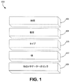
図1は、リンクされたデータのアプローチに従う、感覚データモデル100の意味記述を図示する。このモデルでは、感覚データは、時間属性101と、場所属性103と、タイプ属性105と、値属性107と、他のメタデータへのリンク109とを含む。感覚データは、一般的に使用されているオントロジーおよび語彙で定義される既存の概念にリンクされ得る。そして、詳細なメタデータおよびソース関連属性が、他のソースへのリンクとして提供され得る。モデル100は、そのような感覚データを記述するためのスキーマを提供する。
FIG. 1 illustrates a semantic description of a
ジオハッシュタギングが、例えば、場所属性を記述するために使用され得る。ジオハッシュは、地理的な場所の10進緯度および経度値の文字列ハッシュを作成するために、Base−N符号化およびビットインターリービングを使用する機構である。これは、階層構造を使用し、物理的空間をグリッドに分割する。ジオハッシングは、ジオタギングに使用され得る対称技法である。ジオハッシングの特徴は、(いくつかの例外を伴って)近くの場所が、それらの文字列表現において類似プレフィックスを有するであろうことである。実施例では、緯度および経度地理座標の12バイトハッシュ文字列表現を作成するように、Base32符号化およびビットインターリービングを使用する、ジオハッシングアルゴリズムが採用される。例えば、「51.235401」という緯度値および「0.574600」という経度値を有するGuildfordの場所は、「gcpe6zjeffgp」として表される。 Geo-hash tagging can be used, for example, to describe location attributes. Geohash is a mechanism that uses Base-N encoding and bit interleaving to create a string hash of the decimal latitude and longitude values of a geographic location. This uses a hierarchical structure and divides the physical space into grids. Geohashing is a symmetric technique that can be used for geotagging. A feature of geohashing is that nearby locations (with some exceptions) will have similar prefixes in their string representation. In an embodiment, a geohashing algorithm is employed that uses Base32 encoding and bit interleaving to create a 12-byte hash string representation of latitude and longitude geographic coordinates. For example, a Guildford location having a latitude value “51.235401” and a longitude value “0.574600” is represented as “gcpe6zjeffgp”.
図2は、マップ110上にマークされた大学構内の4つの場所を示す。表2は、マップ110上の異なる場所のジオハッシュ場所タグを示す。表2で観察することができるように、非常に近い場所は、類似プレフィックスを有する。プレフィッックスは、場所間の距離が近くなるほど、より類似する。例えば、位置111、位置112、位置113、および位置114は、最初の6桁を共有する。位置112および位置113は、それらの近さにより、最初の8桁を共有する(他の場所と比較して追加の2桁)。感覚データの名前の中のジオハッシュタグは、例えば、文字列類似性方法の使用により、データを問い合わせること、発見することにおいて場所ベースの検索を提供し得る。場所プレフィックスは、データが非常に近い異なる場所から統合または蓄積される場合に、集計プレフィックスを作成するために使用され得る。例えば、全ての感覚データの間で共有される最長プレフィックス文字列が、データのための集計場所プレフィックスタグを表すために使用され得る。
FIG. 2 shows four locations within the university campus that are marked on the
感覚データモデルのタイプ属性に対して、概念が、地球および環境用語(SWEET)オントロジーのためのNASAのセマンティックウェブから採用され得る。SWEETは、8つの最上位概念/オントロジー、すなわち、表現、プロセス、現象、領域、状態、事柄、人間の活動、および数量から成る。各々は、次のレベルの概念を有する。それらの全ては、感覚データモデルのタイプ属性に対する値であり得る。種々の実施例では、タイプ属性は、共通語彙に基づく既存の概念にリンクされ得る。別の実施例では、感覚データのタイプを記述するためのより具体的なオントロジーが採用され得る。 For sensory data model type attributes, concepts can be adopted from the NASA Semantic Web for the Earth and Environmental Terminology (SWEET) ontology. SWEET consists of eight top-level concepts / ontologies: representation, process, phenomenon, domain, state, matter, human activity, and quantity. Each has the next level of concept. All of them can be values for the type attribute of the sensory data model. In various embodiments, type attributes can be linked to existing concepts based on a common vocabulary. In another embodiment, a more specific ontology for describing the type of sensory data may be employed.
上記のように、図1に示される属性は、感覚データのためのセマンティクスモデル100を形成する。ソース関連データ(すなわち、どのようにしてデータが測定されるか、特定のデバイスの使用、または情報の質)等の追加の特徴が、プロバイダデバイス自体、ゲートウェイ等の他のソース上で利用可能な情報にリンクされ得るように、モジュール形式で追加され得る。図1は、他のメタデータ属性109へのリンクを示す。例えば、情報属性の質または測定範囲性質等を記述するために、新しい意味記述モジュールが追加されることができ、それは、コア記述にリンクされることができる。追加の特徴の追加は、組み込み意味命名を使用してストリーミングセンサデータを記述するための融通性のあるソリューションを提供し、モデルがデータのコア属性を捕捉し、追加の情報がリンクされたデータとして提供され得る。
As described above, the attributes shown in FIG. 1 form a
本発明の側面によると、感覚データは、場所、時間(ストリームに対して、これは、ストリームの現在のウィンドウ内の測定の開始時間であり得る)、およびタイプ等の図1の意味モデル100の属性を含む情報を使用して、名前を付けられ得る。図3に示されるように、例えば、感覚データの識別(ID)(すなわち、組み込み意味名)124を表すように、文字列が作成され得る。図3は、一実施例による、例示的なID構造120を図示する。ID構造120は、場所情報のジオハッシュタグ121を含む場所フィールド121と、タイプ情報(例えば、温度、湿度、または光)のメッセージダイジェストアルゴリズム5(MD5)を含むタイプフィールド122と、時間情報のMD5を含む時間フィールド123とを備え得る。MD5は、暗号ハッシュ関数である。場所フィールド121、タイプフィールド122、および時間フィールド123の中の値は、感覚データの名前として使用されるID124を作成するように組み立てられ得る。本実施例では、ID124は、リソース記述フレームワーク(RDF)の文脈で使用される。RDFは、ウェブ上のリソースを記述するためのフレームワークである。
In accordance with aspects of the present invention, sensory data is obtained from the
同一のタイプの複数のセンサが、多くの場合、重複した感覚示度値を取得して、信頼性のレベル(例えば、デバイス故障)、測定の一貫性等を達成するように、同一の場所で展開される。本明細書で議論される意味モデルは、同一のタイプの複数のセンサが同一の場所にあり、同時に感覚データを提供する場合、感覚データに名前を付けることの問題に対処する。実施例では、デバイス識別子が、図4に示されるように、感覚データの組み込み意味命名とともに使用され得る。図4は、図3に類似するが、DeviceIDフィールド126がID構造128の中に追加される。このフィールドは、組み込み意味名のための形式として使用される。DeviceIDフィールド126で使用されるデバイス識別子は、バーコードまたはRFIDタグ、MACアドレス、移動電話加入者ISDN番号(MSISDN)等であり得る。図4のDeviceIDフィールド126(または任意の他のフィールド)の長さは、デバイス識別子を収容するために任意のバイト数(例えば、12バイト)に設定され得る。ID構造120およびID構造128は、本明細書で議論される属性を反映する感覚データの組み込み意味名を作成する方法である。
Multiple sensors of the same type often obtain duplicate sensory readings to achieve a level of reliability (eg, device failure), measurement consistency, etc. Be expanded. The semantic model discussed herein addresses the problem of naming sensory data when multiple sensors of the same type are in the same location and simultaneously provide sensory data. In an embodiment, the device identifier may be used with built-in semantic naming of sensory data, as shown in FIG. FIG. 4 is similar to FIG. 3, but a
図5は、感覚データの組み込み意味命名のための例示的な方法130を図示する。ステップ131では、感覚データがセンサによって感知された時間が決定される。ステップ133では、感覚データのタイプが決定される。タイプは、感覚データのソースに依存する。例えば、温度を感知するセンサから生じたデータは、温度タイプを有し得、湿度を感知するセンサから生じたデータは、湿度タイプを有し得る。ステップ135では、感覚データを生成するセンサの場所のジオハッシュタグが決定される。ステップ137では、感覚データのタイプ、センサの場所のジオハッシュタグ、および感覚データが感知された時間に基づいて、感覚データの組み込み意味名が構築される。例えば、組み込み意味名は、図3に関して議論されるような例示的構造に従って構築され得る。図4でさらに図示されるように、別の実施例では、組み込み意味名はまた、感覚データのタイプ、センサの場所のジオハッシュタグ、および感覚データが感知された時間とともに、センサのデバイス識別子を含み得る。実施例では、感覚データの名前は、そのソース(例えば、センサ)によって生成され得る。ブロック139では、構築された名前が他のコンピュータデバイスに公開され得る。例えば、センサは、関連感覚データとともに、または関連感覚データとは別に、組み込み意味名をゲートウェイに提供し得る。実施例では、名前作成は、ゲートウェイによって、または専門の命名サーバによって行われ得る。
FIG. 5 illustrates an
方法130に関して、リソース制約されたデバイスに対して、センサによって感覚データの名前を構築することは、比較的有意な量の電力および他のリソースを消費し得る。加えて、センサが感覚データの名前をゲートウェイに公開する場合、公開は、有意な量のネットワーク帯域幅を消費し、名前を転送する際に有意なオーバーヘッドを中間ノードに課し得る。これは特に、中間ノードがリソース制約されたデバイスでもあるときに問題であり得る。いくつかの実施例では、中間ノードは、発信元からゲートウェイへ感覚データを転送する、中継ノードであり得る。例えば、センサネットワーク内で、中間ノードは、発信元センサとゲートウェイとの間のセンサであり得る。
With respect to the
図6は、感覚データに名前を付け、データを公開するための例示的なフロー140を図示する。ステップ143では、デバイス登録要求がセンサ141からゲートウェイ142へ送信され得る。登録要求において、センサ141は、例えば、その場所、デバイス識別子、およびそのサポートされたタイプをゲートウェイ142に知らせ得る。場所は、ジオハッシュ、経度および緯度、都市の場所、特定の物理的アドレス等の形態であり得る。場所情報がジオハッシュの形態ではない場合、ゲートウェイ142は、受信した場所をジオハッシュタグの形式(または別の所望の場所形式)に変換することに関与し得る。センサ141は、1つの場所から別の場所へ移動し得、かつ場所の変化を示すためにゲートウェイ142に再登録し得る。センサ141による場所の変化の登録は、設定された時間に、設定された期間に(例えば、10秒の時間間隔で)、または特定の所定場所に到達したときに起こり得、これは、場所を頻繁に変更するデバイスにとって好ましくあり得る。ゲートウェイ142によってMD5形式で記憶され得る、センサ141が行う感知のタイプもまた、ステップ143での登録要求に含まれ得る。センサ141は、1つより多くのタイプの感知(例えば、温度および湿度)をサポートし得る。ゲートウェイ142は、ラベルをセンサ141によって行われる各タイプの感知に割り当て得る(例えば、温度が1というラベルを有する一方で、湿度は2というラベルを有する)。
FIG. 6 illustrates an exemplary flow 140 for naming sensory data and publishing the data. In
ステップ144では、ゲートウェイ142が、センサ141から受信されるであろう感覚データのストリームを記憶するためのエントリーを構築する。表3は、受信され、ステップ144でゲートウェイによって構築されるセンサエントリーに記憶され得る、あるセンサ情報の実施例を示す。示されるように、本実施例では、センサ情報は、とりわけ、センサのデバイス識別子、センサの場所、およびセンサがサポートする感知のタイプを含み得る。ステップ145では、ゲートウェイ142が、デバイス登録に応答したメッセージをセンサ141に送信し、メッセージは、センサ141によってサポートされる1つより多くのタイプがある場合、タイプのラベルを含む。タイプラベル(例えば、表3内の1または2)は、公開されるデータのタイプを示す。タイプの対応するMD5が、デバイス情報から読み出される。ステップ146では、センサ141が、感覚データ値(例えば、温度)、感覚データが感知された時(例えば、正午)、センサの場所(例えば、経度および緯度)、センサのデバイス識別子(例えば、MACアドレス)、およびタイプラベル(例えば、1)を含み得る、感覚データをゲートウェイ142に公開する。ステップ147では、ゲートウェイ142が、図1、図3、および図4で図示され、上記で説明される、例示的命名技法/構造および感覚データモデルに従って、公開されたデータの組み込み意味名を生成することができる。
In step 144,
議論されるように、本明細書で開示される感覚データモデルおよび命名プロシージャを用いると、場所、ソース、タイプ、および時間等の感覚データのセマンティクスが、その名前に組み込まれ得る。したがって、ゲートウェイが感覚データの名前を他のエンティティ(例えば、別のゲートウェイまたはサーバ)に公開すると、名前に組み込まれたデータのセマンティクスは、元のデータ公開元(例えば、ゲートウェイ142)から読み出される必要がない。 As discussed, using the sensory data model and naming procedures disclosed herein, the semantics of sensory data such as location, source, type, and time can be incorporated into the name. Thus, when a gateway publishes a sensory data name to another entity (eg, another gateway or server), the data semantics embedded in the name need to be read from the original data publisher (eg, gateway 142). There is no.
図7は、アプリケーション154が感覚データを読み出し、次いで、関連セマンティクスを受信する、感覚データクエリフローを図示する。ステップ155では、センサ151が(例えば、図6に関して本明細書で議論されるように)感覚データを公開する。ステップ156では、ゲートウェイ152が、感覚データの組み込み意味名をサーバ153に送信する。ステップ157では、アプリケーション154が、データを要求するメッセージをサーバ153に送信する。ステップ159では、サーバ153が、センサ151によって感知される感覚データの値を読み出すために、要求をゲートウェイ152に転送する。ステップ160では、ゲートウェイ152が、感覚データの値をアプリケーション154に転送するサーバ153に感覚データの値を提供する。161で受信される感覚データが、アプリケーション154が所望する属性と対応する組み込み意味命名を有する場合には、さらなるセマンティクス情報が必要とされない。しかし、アプリケーション154が、感覚データを理解して使用するために、組み込み意味命名によって提供されない、さらなる情報を必要とする場合、アプリケーション154は、感覚データのセマンティクスを要求し得る。随意的なステップ162では、アプリケーション154が、要求される感覚データのセマンティクス(例えば、場所、タイプ、時間、およびソース)を要求する。ステップ164では、サーバ153が、感覚データのセマンティクスを転送する。実装に基づいて、アプリケーションは、サーバ153、ゲートウェイ152、センサ151、または別のデバイスからセマンティクス情報を読み出し得る。本明細書で議論されるように、セマンティクス情報は、どのようにして異なる形式のデータを解釈するかに関してアプリケーションを支援し得る。
FIG. 7 illustrates a sensory data query flow in which application 154 retrieves sensory data and then receives relevant semantics. In
本願の別の側面によると、感覚データの組み込みセマンティクスを用いた、開示された命名方式は、データ集計を促進する。具体的には、データ集計は、どのようにして集計を行うかを命令するためにいかなる追加の情報も伴わずに、上記で説明される様式で、感覚データのために作成される名前の中のフィールド(例えば、センサの場所、タイプ、または時間)を使用することによって、自動的に行うことができる。集計は、データ生成側(例えば、センサ)で、データ生成側とデータ収集側との間の同一のジオハッシュ場所を伴う中間ノード、およびデータ収集側(例えば、ゲートウェイ)で起こり得る。センサの属性(例えば、場所、デバイス識別子、およびサポートされたタイプ)は、頻繁に変化しないこともある。センサにおけるデータ集計は、有意な期間(例えば、数分、数時間、数日、または数ヶ月)にわたって行われ得、これは、センサが、感知する度に感覚データを公開する必要がないこともあることを意味する。センサは、ある期間にわたって感知されるデータを集計し得る(例えば、30分の期間で全ての感覚データという平均)。この場合、集計されたデータの意味名に組み込まれる時間属性は、集計されたデータの期間であり得る。 According to another aspect of the present application, the disclosed nomenclature using embedded semantics of sensory data facilitates data aggregation. Specifically, data aggregation is a name created for sensory data in the manner described above, without any additional information to instruct how to perform the aggregation. This can be done automatically by using a field (eg, sensor location, type, or time). Aggregation can occur at the data generation side (eg, sensor), at an intermediate node with the same geo-hash location between the data generation side and the data collection side, and at the data collection side (eg, gateway). Sensor attributes (eg, location, device identifier, and supported types) may not change frequently. Data aggregation at the sensor can take place over a significant period of time (eg, minutes, hours, days, or months), even if the sensor does not need to publish sensory data each time it senses. It means that there is. The sensor may aggregate data sensed over a period of time (eg, an average of all sensory data over a 30 minute period). In this case, the time attribute incorporated in the semantic name of the aggregated data can be the period of the aggregated data.
感覚データの組み込みセマンティクスを用いた、開示された命名方式はまた、感覚データのクラスタリングを促進するために使用され得る。K平均法(ベクトル量子化の方法)等のクラスタリング機構が、感覚データを異なるレポジトリにクラスタ化するために使用され得る。クラスタリングモデルに基づく予測方法の使用は、データの各部分を維持するレポジトリの識別を可能にし得る。例えば、各レポジトリは、場所、デバイス、タイプ、または時間等の感覚データの1つのタイプのクラスタリングを維持し得る。 The disclosed nomenclature with sensory data built-in semantics can also be used to facilitate clustering of sensory data. A clustering mechanism such as the K-means method (vector quantization method) can be used to cluster sensory data into different repositories. The use of a prediction method based on a clustering model may allow identification of the repository that maintains each piece of data. For example, each repository may maintain one type of clustering of sensory data such as location, device, type, or time.
データ集計を促進するために、開示された意味命名方式をどのようにして使用することができるかという概念をさらに例証するため、ならびに記憶された感覚データの発見およびクエリをどのようにして行うことができるかを例証するために、図8は、本明細書で説明される感覚データに名前を付けるための意味モデルを実装する、システム170の一実施例のブロック図を提供する。図8では、場所175は、センサ171、センサ172、およびセンサ173を含む、複数の通信可能に接続されたセンサを含む。センサ172およびセンサ173は、センサ171とゲートウェイ174との間の中間ノードである。ゲートウェイ174は、ネットワーク176を介して、領域175および発見サーバ178に通信可能に接続される。
To further illustrate the concept of how the disclosed semantic naming scheme can be used to facilitate data aggregation and how to discover and query stored sensory data 8 illustrates a block diagram of an example of a
ゲートウェイ174(または別のコンピュータデバイス)は、センサ171、センサ172、およびセンサ173からの感覚データの収集側として、感覚データを集計し、名前の中の異なるフィールド(例えば、場所、デバイス識別子、タイプ等)にわたって集計されたデータの意味名を統合し得る。ゲートウェイ174または別のコンピュータデバイスは、感覚データを集計するための規則またはポリシーを事前に定義し得る。例えば、ゲートウェイ172は、Manhattan、Brooklyn、およびQueensにおけるセンサ示度値を平均化するポリシーを有し得る。Manhattan、Brooklyn、およびQueensの平均感覚示度値は、「New York City」という場所識別子、またはいくつかのセンサジオハッシュの最初のいくつかの共通文字(例えば、「gpced」)を有する単一の代表的ジオハッシュを有し得る。別の実施例では、10月、11月、および12月の示度値が平均化され、冬の単一の代表的時間識別子を有し得る。
The gateway 174 (or another computing device) acts as a sensory data collector from the sensor 171,
実施例では、センサ171、センサ172、およびセンサ173は、温度タイプをサポートし得る。センサ171は、特定の時間「t1」に、意味命名を伴う感覚データのゲートウェイ174に対する公開を開始し得る。センサ172は、センサ171と同一のジオハッシュ場所を有する(センサ171(例えば、最初のデータ生成側)とゲートウェイ174(例えば、データ収集側)との間の中間ノードである)。センサ172は、受信した感覚データを、場所175に位置するデバイスに対する(時間t1またはその付近でセンサ172によって感知される)感知された感覚データと集計し得る。この感覚データの集計は、センサ172が、ゲートウェイ174に向かうことになっている、前のホップ(例えば、センサ171)から感覚データを受信するときにトリガされ得る。集計された感覚データは、意味名において、センサ171によって公開される、最初に公開された感覚データと同一のデバイス識別子(例えば、DeviceIDフィールド126で使用される識別子)を割り当てられ得る。別の実施例では、デバイス識別子は、感覚データ集計を行った、または感覚データを転送した最後のセンサ(中間ノード)のみを反映し得る。別の実施例では、デバイス識別子は、感覚データ集計に参加した、または感覚データを転送したセンサの識別子の組み合わせを反映し得る。さらに別の実施例では、異なるセンサからの複数の感覚データが、同一値、類似値、平均値等を有し得るため、異なるセンサからの複数の感覚データは、1つの一意の命名を伴う1つのデータとして扱われ得る。
In an embodiment, sensor 171,
再度、図8を参照すると、ゲートウェイ174は、元の感覚データとともに、集計された感覚データを、発見機能性を有する発見サーバ178に公開し得る。集計されたデータは、低レベルコンテキスト情報として、生成され、ゲートウェイ174に記憶され得、それは、アプリケーションによって問い合わせられ、高レベルコンテキスト情報を導出するために使用され得る。感覚データのクエリは、いくつかの属性から、また、いくつかのソースからの情報を組み合わせ得る。感覚データのストリームからの可能なクエリのタイプは、厳密クエリ、近似クエリ、範囲クエリ、または複合クエリとして識別され得る。厳密クエリは、タイプ、場所、または時間属性等の既知のデータ属性を要求することを伴う。情報の質(QoI)または測定の単位等の他のメタデータ属性もまた、厳密クエリに含まれ得る。近接クエリは、近似場所からの、または情報の質の閾値を伴うデータを要求することを伴う。範囲クエリは、データに問い合わせを行うために使用される時間範囲または場所範囲を要求することを伴う。複合クエリは、そのデータソースとして別のクエリを使用する、クエリである。複合クエリは、異なるソースからの、時として、異なるタイプを伴うデータの統合(および処理)によって提供されているクエリの結果を伴い得る。どのようにしてデータを統合または集計するかについての規則または方針が、複合クエリとともに提供され得る。例えば、データは、3月1日および2日の週末の間に感知される、タイプ温度および湿度を伴うCityXの場所に基づいて、問い合わせられ得る。
Referring again to FIG. 8, the
本明細書で開示される組み込み意味命名方式は、これらの種類のクエリが行われ、処理されることを可能にする。クエリは、感覚データの組み込み意味名の中のフィールドのうちの1つにマップされ得る。実施例では、範囲クエリに対して、時間または場所範囲ベースのクエリに対する応答は、発見サーバ178が感覚データ名の中の時間および場所フィールドにクエリを直接マップすることを反映し得る。別の実施例では、複合クエリに対して、ソースおよびタイプベースのクエリに対する応答は、発見サーバ178が逆規則/ポリシーを直接適用し、それらを感覚データ名の中の場所、タイプ、時間、およびソースフィールドにマップすることを反映し得る。別の実施例では、近接クエリに対して、クエリは、場所を近似するために、感覚データ名の中のジオハッシュの初期プレフィックスを使用し得る。近接クエリに対する応答は、ジオハッシュフィールドへのジオハッシュのプレフィックスのマッピングに基づき得る。
The built-in semantic naming scheme disclosed herein allows these types of queries to be made and processed. The query can be mapped to one of the fields in the built-in semantic name of the sensory data. In an example, for a range query, the response to the time or location range based query may reflect that
図8に示されるように、時間180、場所181、タイプ182、またはソース183(例えば、デバイス識別子)が、発見サーバ178によって処理されるクエリの発見識別子(発見ID)179を作成するために入力され得る。本実施例では、意味名と比較される発見ID179を入力することによって、感覚データが見出され得る。本質的に、発見ID179は、クエリのパラメータ(例えば、時間、場所、タイプ、またはソース)を反映するという点で、クエリである。発見サーバ178は、独立型コンピュータデバイス、またはゲートウェイ174あるいは別のサーバ内に常駐する論理エンティティであり得る。厳密クエリに対して、発見ID179は、時間180、場所181、タイプ182、またはソース183であり得る。近接クエリに対して、発見ID179は、ジオハッシュのあるプレフィックスであり得る。範囲クエリに対して、発見ID179は、場所範囲または時間範囲から成り得る。複合クエリに対して、発見ID179は、指定ポリシーを伴う時間180、場所181、タイプ182、またはソース183から成り得る。
As shown in FIG. 8,
感覚データの組み込み意味名公開、集計、およびクエリのための開示されたプロシージャは、とりわけ、ハイパーテキスト転送プロトコル(HTTP)または制約アプリケーションプロトコル(CoAP)等の1つ以上の既存のプロトコルに結合され得る。そうするために、HTTPまたはCoAP等のプロコルは、要求および応答を搬送するための下層転送プロトコルとして使用され得る。要求および応答は、HTTP/CoAPメッセージのペイロードに封入され得、または代替として、要求および応答内のある情報は、HTTP/CoAPヘッダおよび/またはオプション内のフィールドに結合され得る。実施例では、組み込み意味名公開、データ集計、およびデータクエリ要求および応答プロトコルプリミティブは、HTTPまたはCoAP要求および応答のペイロードで搬送される、Java(登録商標)Scriptオブジェクト表記(JSON)または拡張マークアップ言語(XML)記述として符号化され得る。本明細書で開示される実施例はまた、先進メッセージ待ち行列プロトコル(AMQP)またはメッセージ待ち行列テレメトリトランスポート(MQTT)を伴い得る。 The disclosed procedures for embedded semantic name publishing, aggregation, and querying of sensory data can be combined with one or more existing protocols such as, among other things, hypertext transfer protocol (HTTP) or constrained application protocol (CoAP) . To do so, a protocol such as HTTP or CoAP can be used as a lower layer transport protocol for carrying requests and responses. Requests and responses can be encapsulated in the payload of an HTTP / CoAP message, or alternatively, some information in the request and response can be combined with fields in the HTTP / CoAP header and / or options. In an embodiment, built-in semantic name disclosure, data aggregation, and data query request and response protocol primitives are carried in HTTP or CoAP request and response payloads, Java® Script Object Representation (JSON) or Extended Markup. Can be encoded as a language (XML) description. The embodiments disclosed herein may also involve Advanced Message Queuing Protocol (AMQP) or Message Queuing Telemetry Transport (MQTT).
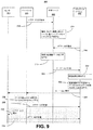
図9は、上で開示される技法および機構による、感覚データクエリフロー200の一実施例を図示する。図9のフロー200は、要求および応答がHTTPプロトコルに従って搬送される、データクエリを図示する。図9を参照すると、ゲートウェイ203は、センサ201等のセンサによって感知されるデータを収集する。ステップ210では、ゲートウェイ203が、HTTP POST要求メッセージを発見サーバ205に送信する。ステップ210でのHTTP POST要求メッセージは、本明細書で説明される意味命名方式が適用されている、感覚データのペイロードを含む。POSTは、HTTPプロトコルによってサポートされる方法であり、ウェブサーバが記憶するために要求メッセージの本体に封入されるデータを受け入れることを要求するように設計されている。
FIG. 9 illustrates one example of a sensory
ステップ214では、発見サーバ205が、場所、タイプ、時間、またはソースの属性に基づいて、任意の受信した感覚データのインデックスを作成し得、例えば、感覚データの各項目の意味名から読み出し、これは、感覚データの発見およびクエリを促進する。発見サーバ205によって受信される感覚データは、本明細書で説明されるように、公開された元の感覚データおよび/またはゲートウェイ203からの公開された集計データであり得る。発見サーバ205はさらに、過去のクエリ要求または結果からの予測に基づいて、データを集計し得る。ステップ216では、HTTP GET要求メッセージが、クライアントデバイス207(例えば、ユーザ機器)によって発見サーバ205に送信され得る。GETは、HTTPプロトコルによってサポートされる方法であり、特定リソースからデータを要求するために設計されている。ステップ216で送信されるHTTP GET要求メッセージは、場所、タイプ、時間、またはソースパラメータから成る発見IDを伴う発見要求を備え得る。ステップ218では、発見サーバ205が、発見IDの中のフィールドを記憶された感覚データの組み込み意味名のフィールドと比較することによって、ステップ216で受信される発見IDを感覚データと照合する。発見サーバ205は、感覚データ意味名フィールドの中の特定のフィールド(バイト)を見る。発見サーバ205は、クエリが既存のフィールドに合致する場合、感覚データの追加のセマンティクス情報を必要としないこともある。合致する感覚データを見出すことにおける発見サーバ205のオーバーヘッド(例えば、必要とされる処理)は、組み込み意味命名により、有意に少なくあり得る。ステップ220では、HTTP GET応答メッセージが、要求クライアントデバイス207に送信される。HTTP GET応答メッセージのペイロードは、ステップ216での要求に対応する、合致する感覚データ名を有する。
In
ステップ222では、クライアントデバイス207が、将来の使用のために感覚データ名の発見結果を記憶する。ステップ224では、クライアントデバイス207が、記憶された感覚データ名に合致する、データを読み出すことを決定し得る。ステップ226では、クライアントデバイスが読み出すことを希望する感覚データの名前を含むペイロードとともに、HTTP GET要求メッセージが、センサ201またはゲートウェイ203に送信され得る。いずれにしても、ステップ228では、ゲートウェイ203は、要求された感覚データがゲートウェイ203上に記憶されるかどうかを決定し得る。ステップ226で送信されるHTTP GET要求は、ゲートウェイ203によって途中で捕獲され得、ゲートウェイ203は、組み込み意味名のみの代わりに、センサ201が合致するデータ値を公開したかどうかを決定するためにチェックし得る。ゲートウェイ203が合致するデータ値を有する場合、ゲートウェイ203は、ステップ230で、適切な感覚データ値を含むHTTP GET応答メッセージで返信し得る。ゲートウェイ203は、要求された感覚データが任意の他のクライアントによって以前に読み出されていた場合、要求された感覚データ値のキャッシュされたコピーを保持し得る。実施例では、ゲートウェイ203が公開されたデータ値のコピーを有さないとき、ステップ232で、ゲートウェイ203は、ステップ226で送信されるHTTP GET要求をセンサ201に転送し得る。ステップ234では、センサ201が、最初にステップ226で送信されたHTTP GET要求に応答するように送信されるHTTP GET応答で、応答し得る。
In
図10Aは、1つ以上の開示された実施例が実装され得る、例示的マシンツーマシン(M2M)またはモノのインターネット(IoT)通信システム10の略図である。概して、M2M技術は、IoTのための構成要素を提供し、任意のM2Mデバイス、ゲートウェイ、またはサービスプラットフォームは、IoTの構成要素ならびにIoTサービス層等であり得る。
FIG. 10A is a schematic diagram of an example machine-to-machine (M2M) or Internet of Things (IoT)
図10Aに示されるように、M2M/IoT通信システム10は、通信ネットワーク12を含む。通信ネットワーク12は、固定ネットワークまたは無線ネットワーク(例えば、WLAN、セルラー等)、あるいは異種ネットワークのネットワークであり得る。例えば、通信ネットワーク12は、音声、データ、ビデオ、メッセージング、ブロードキャスト等のコンテンツを複数のユーザに提供する、複数のアクセスネットワークから成り得る。例えば、通信ネットワーク12は、符号分割多重アクセス(CDMA)、時分割多重アクセス(TDMA)、周波数分割多重アクセス(FDMA)、直交FDMA(OFDMA)、単一キャリアFDMA(SC−FDMA)等の1つ以上のチャネルアクセス方法を採用し得る。さらに、通信ネットワーク12は、例えば、コアネットワーク、インターネット、センサネットワーク、工業制御ネットワーク、パーソナルエリアネットワーク、融合個人ネットワーク、衛星ネットワーク、ホームネットワーク、または企業ネットワーク等の他のネットワークを備え得る。
As shown in FIG. 10A, the M2M /
図10Aに示されるように、M2M/IoT通信システム10は、M2Mゲートウェイデバイス14と、M2M端末デバイス18とを含み得る。任意の数のM2Mゲートウェイデバイス14およびM2M端末デバイス18が、所望に応じてM2M/IoT通信システム10に含まれ得ることが理解されるであろう。M2Mゲートウェイデバイス14およびM2M端末デバイス18の各々は、通信ネットワーク12または直接無線リンクを介して、信号を伝送および受信するように構成される。M2Mゲートウェイデバイス14は、無線M2Mデバイス(例えば、セルラーおよび非セルラー)ならびに固定ネットワークM2Mデバイス(例えば、PLC)が、通信ネットワーク12等のオペレータネットワークを通して、または直接無線リンクを通してのいずれかで、通信することを可能にする。例えば、M2Mデバイス18は、データを収集し、通信ネットワーク12または直接無線リンクを介して、データをM2Mアプリケーション20またはM2Mデバイス18に送信し得る。M2Mデバイス18はまた、M2Mアプリケーション20またはM2Mデバイス18からデータを受信し得る。さらに、データおよび信号は、以下で説明されるように、M2Mサービスプラットフォーム22を介して、M2Mアプリケーション20に送信され、そこから受信され得る。M2Mデバイス18およびゲートウェイ14は、例えば、セルラー、WLAN、WPAN(例えば、Zigbee(登録商標)、6LoWPAN、Bluetooth(登録商標))、直接無線リンク、および有線を含む、種々のネットワークを介して通信し得る。
As shown in FIG. 10A, the M2M /
図示したM2Mサービスプラットフォーム22は、M2Mアプリケーション20、M2Mゲートウェイデバイス14、M2M端末デバイス18、および通信ネットワーク12のためのサービスを提供する。M2Mサービスプラットフォーム22は、所望に応じて、任意の数のM2Mアプリケーション、M2Mゲートウェイデバイス14、M2M端末デバイス18、および通信ネットワーク12と通信し得ることが理解されるであろう。M2Mサービスプラットフォーム22は、1つ以上のサーバ、コンピュータ等によって実装され得る。M2Mサービスプラットフォーム22は、M2M端末デバイス18およびM2Mゲートウェイデバイス14の管理および監視等のサービスを提供する。M2Mサービスプラットフォーム22はまた、データを収集し、異なるタイプのM2Mアプリケーション20と適合性があるようにデータを変換し得る。M2Mサービスプラットフォーム22の機能は、例えば、ウェブサーバとして、セルラーコアネットワークで、クラウドで等、種々の方法で実装され得る。
The illustrated
図10Bも参照すると、M2Mサービスプラットフォームは、典型的には、多様なアプリケーションおよび垂直線が活用することができる、サービス配信能力のコアセットを提供する、サービス層26(例えば、ネットワークサービス能力層(NSCL))を実装する。これらのサービス能力は、M2Mアプリケーション20がデバイスと相互作用し、データ収集、データ分析、デバイス管理、セキュリティ、課金、サービス/デバイス発見等の機能を果たすことを可能にする。本質的に、これらのサービス能力は、これらの機能性を実装する負担をアプリケーションから取り除き、したがって、アプリケーション開発を単純化し、市場に出す費用および時間を削減する。サービス層26はまた、M2Mアプリケーション20が、サービス層26が提供するサービスと関連して、種々のネットワーク12を通して通信することも可能にする。
Referring also to FIG. 10B, the M2M service platform typically provides a service layer 26 (eg, a network service capability layer (eg, a network service capability layer) that provides a core set of service delivery capabilities that can be utilized by a variety of applications and verticals. NSCL)). These service capabilities allow the
いくつかの実施例では、M2Mアプリケーション20は、本明細書で議論されるように、組み込み意味命名を伴う感覚データを読み出して通信する、所望のアプリケーションを含み得る。M2Mアプリケーション20は、限定ではないが、輸送、保健および健康、コネクテッドホーム、エネルギー管理、アセット追跡、ならびにセキュリティおよび監視等の種々の業界でのアプリケーションを含み得る。上記のように、本システムのデバイス、ゲートウェイ、および他のサーバにわたって作動するM2Mサービス層は、例えば、データ収集、デバイス管理、セキュリティ、課金、場所追跡/ジオフェンシング、デバイス/サービス発見、およびレガシーシステム統合等の機能をサポートし、サービス等のこれらの機能をM2Mアプリケーション20に提供する。
In some examples, the
図10Cは、例えば、M2M端末デバイス18またはM2Mゲートウェイデバイス14等の例示的M2Mデバイス30の系統図である。図10Cに示されるように、M2Mデバイス30は、プロセッサ32と、送受信機34と、伝送/受信要素36と、スピーカ/マイクロホン38と、キーパッド40と、ディスプレイ/タッチパッド42と、非取り外し可能メモリ44と、取り外し可能メモリ46と、電源48と、全地球測位システム(GPS)チップセット50と、他の周辺機器52とを含み得る。M2Mデバイス40は、実施例と一致したままで、先述の要素の任意の副次的組み合わせを含み得ることが理解されるであろう。このデバイスは、感覚データの組み込み意味命名のための開示されたシステムおよび方法を使用する、デバイスであり得る。
FIG. 10C is a system diagram of an
プロセッサ32は、汎用プロセッサ、特殊用途プロセッサ、従来のプロセッサ、デジタル信号プロセッサ(DSP)、複数のマイクロプロセッサ、DSPコアと関連する1つ以上のマイクロプロセッサ、コントローラ、マイクロコントローラ、特定用途向け集積回路(ASIC)、フィールドプログラマブルゲートアレイ(FPGA)回路、任意の他のタイプの集積回路(IC)、状態機械等であり得る。プロセッサ32は、信号符号化、データ処理、電力制御、入出力処理、および/またはM2Mデバイス30が無線環境で動作することを可能にする任意の他の機能性を果たし得る。プロセッサ32は、伝送/受信要素36に連結され得る、送受信機34に連結され得る。図10Cは、プロセッサ32および送受信機34を別個の構成要素として描写するが、プロセッサ32および送受信機34は、電子パッケージまたはチップにともに組み込まれ得ることが理解されるであろう。プロセッサ32は、アプリケーション層プログラム(例えば、ブラウザ)および/または無線アクセス層(RAN)プログラムおよび/または通信を行い得る。プロセッサ32は、例えば、アクセス層および/またはアプリケーション層等で、認証、セキュリティキー一致、および/または暗号化動作等のセキュリティ動作を行い得る。
The
伝送/受信要素36は、信号をM2Mサービスプラットフォーム22に伝送し、またはM2Mサービスプラットフォーム22から信号を受信するように構成され得る。例えば、実施例では、伝送/受信要素36は、RF信号を伝送および/または受信するように構成されるアンテナであり得る。伝送/受信要素36は、WLAN、WPAN、セルラー等の種々のネットワークおよびエアインターフェースをサポートし得る。実施例では、伝送/受信要素36は、例えば、IR、UV、または可視光信号を伝送および/または受信するように構成されるエミッタ/検出器であり得る。さらに別の実施例では、伝送/受信要素36は、RFおよび光信号の両方を伝送および受信するように構成され得る。伝送/受信要素36は、無線または有線信号の任意の組み合わせを伝送および/または受信するように構成され得ることが理解されるであろう。
The transmit / receive
加えて、伝送/受信要素36は、単一の要素として図10Cで描写されているが、M2Mデバイス30は、任意の数の伝送/受信要素36を含み得る。より具体的には、M2Mデバイス30は、MIMO技術を採用し得る。したがって、実施例では、M2Mデバイス30は、無線信号を伝送および受信するための2つまたはそれを上回る伝送/受信要素36(例えば、複数のアンテナ)を含み得る。
In addition, although the transmit / receive
送受信機34は、伝送/受信要素36によって伝送される信号を変調するように、および伝送/受信要素36によって受信される信号を変調するように構成され得る。上記のように、M2Mデバイス30は、マルチモード能力を有し得る。したがって、送受信機34は、M2Mデバイス30が、例えば、UTRAおよびIEEE802.11等の複数のRATを介して通信することを可能にするための複数の送受信機を含み得る。
The
プロセッサ32は、非取り外し可能メモリ44および/または取り外し可能メモリ46等の任意のタイプの好適なメモリから情報にアクセスし、そこにデータを記憶し得る。非取り外し可能メモリ44は、ランダムアクセスメモリ(RAM)、読み取り専用メモリ(ROM)、ハードディスク、または任意の他のタイプのメモリ記憶デバイスを含み得る。取り外し可能メモリ46は、加入者識別モジュール(SIM)カード、メモリスティック、セキュアデジタル(SD)メモリカード等を含み得る。他の実施例では、プロセッサ32は、サーバまたはホームコンピュータ上等のM2Mデバイス30上に物理的に位置しないメモリから情報にアクセスし、そこにデータを記憶し得る。プロセッサ32は、感覚データの組み込み意味命名に応答して、ディスプレイまたはインジケータ42上の照明パターン、画像、テキスト、または色を制御するように構成され得る。本明細書で説明される実施例は、成功しているか、または成功していないか、あるいは別様に組み込み意味命名を伴うプロセスステップの状態を示す。
The
プロセッサ32は、電源48から電力を受容し得、M2Mデバイス30内の他の構成要素への電力を分配および/または制御するように構成され得る。電源48は、M2Mデバイス30に電力供給するための任意の好適なデバイスであり得る。例えば、電源48は、1つ以上の乾電池バッテリ(例えば、ニッケルカドミウム(NiCd)、ニッケル亜鉛(NiZn)、ニッケル水素(NiMH)、リチウムイオン(Li−ion)等)、太陽電池、燃料電池等を含み得る。
The
プロセッサ32はまた、M2Mデバイス30の現在の場所に関する場所情報(例えば、経度および緯度)を提供するように構成される、GPSチップセット50に連結され得る。M2Mデバイス30は、実施形態と一致したままで、任意の公的な場所決定方法を介して場所情報を獲得し得ることが理解されるであろう。
The
プロセッサ32はさらに、追加の特徴、機能性、および/または有線あるいは無線接続を提供する、1つ以上のソフトウェアおよび/またはハードウェアモジュールを含み得る、他の周辺機器52に連結され得る。例えば、周辺機器52は、加速度計、e−コンパス、衛星送受信機、センサ、デジタルカメラ(写真またはビデオ用)、ユニバーサルシリアルバス(USB)ポート、振動デバイス、テレビ送受信機、ハンズフリーヘッドセット、Bluetooth(登録商標)モジュール、周波数変調(FM)ラジオユニット、デジタル音楽プレーヤ、メディアプレーヤ、ビデオゲームプレーヤモジュール、インターネットブラウザ等を含み得る。
The
図10Dは、例えば、図10Aおよび10BのM2Mサービスプラットフォーム22が実装され得る、例示的なコンピュータシステム90のブロック図である。コンピュータシステム90は、コンピュータまたはサーバを備え得、主に、ソフトウェアの形態であり得るコンピュータ読み取り可能な命令によって制御され得、どこでも、またはどのような手段を用いても、そのようなソフトウェアが記憶あるいはアクセスされる。そのようなコンピュータ読み取り可能な命令は、コンピュータシステム90を稼働させるように、中央処理装置(CPU)91内で実行され得る。多くの既知のワークステーション、サーバ、および周辺コンピュータでは、中央処理装置91は、マイクロプロセッサと呼ばれる単一チップCPUによって実装される。他の機械では、中央処理装置91は、複数のプロセッサを備え得る。コプロセッサ81は、追加の機能を果たすか、またはCPU91を支援する、主要CPU91とは明確に異なる、随意的なプロセッサである。CPU91および/またはコプロセッサ81は、組み込み意味名を伴う感覚データのクエリ等の組み込み意味命名のための開示されたシステムおよび方法に関係付けられるデータを受信、生成、および処理し得る。
FIG. 10D is a block diagram of an
動作中、CPU91は、命令をフェッチ、復号、および実行し、コンピュータの主要データ転送経路であるシステムバス80を介して、情報を他のリソースへ、およびそこから転送する。そのようなシステムバスは、コンピュータシステム90内の構成要素を接続し、データ交換のための媒体を定義する。システムバス80は、典型的には、データを送信するためのデータライン、アドレスを送信するためのアドレスライン、ならびに割り込みを送信するため、およびシステムバスを動作するための制御ラインを含む。そのようなシステムバス80の実施例は、PCI(周辺構成要素相互接続)バスである。
During operation, the
システムバス80に連結されるメモリデバイスは、ランダムアクセスメモリ(RAM)82および読み取り専用メモリ(ROM)93を含む。そのようなメモリは、情報が記憶されて読み出しされることを可能にする回路を含む。ROM93は、概して、容易に修正することができない、記憶されたデータを含有する。RAM82に記憶されたデータは、CPU91または他のハードウェアデバイスによって読み取られ、または変更されることができる。RAM82および/またはROM93へのアクセスは、メモリコントローラ92によって制御され得る。メモリコントローラ92は、命令が実行されると、仮想アドレスを物理的アドレスに変換する、アドレス変換機能を提供し得る。メモリコントローラ92はまた、システム内のプロセスを分離し、ユーザプロセスからシステムプロセスを分離する、メモリ保護機能を提供し得る。したがって、第1のモードで作動するプログラムは、独自のプロセス仮想アドレス空間によってマップされるメモリのみにアクセスすることができ、プロセス間のメモリ共有が設定されていない限り、別のプロセスの仮想アドレス空間内のメモリにアクセスすることができない。
Memory devices coupled to the
加えて、コンピュータシステム90は、CPU91からプリンタ94、キーボード84、マウス95、およびディスクドライブ85等の周辺機器に命令を伝達する責任がある、周辺機器コントローラ83を含み得る。
In addition, the
ディスプレイコントローラ96によって制御されるディスプレイ86は、コンピュータシステム90によって生成される視覚出力を表示するために使用される。そのような視覚出力は、テキスト、グラフィックス、動画グラフィックス、およびビデオを含み得る。ディスプレイ86は、CRTベースのビデオディスプレイ、LCDベースのフラットパネルディスプレイ、ガスプラズマベースのフラットパネルディスプレイ、またはタッチパネルを伴って実装され得る。ディスプレイコントローラ96は、ディスプレイ86に送信されるビデオ信号を生成するために必要とされる、電子構成要素を含む。ディスプレイ86は、組み込み意味名を使用して、ファイルまたはフォルダの中の感覚データを表示し得る。例えば、図3、図4等に示される形式でのフォルダの名前である。
A
さらに、コンピュータシステム90は、図10Aおよび10Bのネットワーク12等の外部通信ネットワークにコンピュータシステム90を接続するために使用され得る、ネットワークアダプタ97を含み得る。
In addition, the
本明細書で説明されるシステム、方法、およびプロセスのうちのいずれかまたは全ては、命令が、コンピュータ、サーバ、M2M端末デバイス、M2Mゲートウェイデバイス等の機械によって実行されると、本明細書で説明されるシステム、方法、およびプロセスを行うおよび/または実装される、コンピュータ読み取り可能な記憶媒体上に記憶されたコンピュータ実行可能命令(すなわち、プログラムコード)の形態で具現化され得ることが理解される。具体的には、上記で説明されるステップ、動作、または機能のうちのいずれかは、そのようなコンピュータ実行可能命令の形態で実装され得る。コンピュータ読み取り可能な記憶媒体は、情報の記憶のための任意の方法または技術で実装される、揮発性および不揮発性、取り外し可能および非取り外し可能媒体の両方を含むが、そのようなコンピュータ読み取り可能な記憶媒体は、信号を含まない。コンピュータ読み取り可能な記憶媒体は、RAM、ROM、EEPROM、フラッシュメモリまたは他のメモリ技術、CDROM、デジタル多用途ディスク(DVD)または他の光学ディスク記憶装置、磁気カセット、磁気テープ、磁気ディスク記憶装置または他の磁気記憶デバイス、あるいは所望の情報を記憶するために使用することができ、コンピュータによってアクセスすることができる任意の他の物理的媒体を含むが、それらに限定されない。 Any or all of the systems, methods, and processes described herein are described herein when instructions are executed by a machine such as a computer, server, M2M terminal device, M2M gateway device, or the like. It is understood that the present invention can be embodied in the form of computer-executable instructions (ie, program code) stored on a computer-readable storage medium that perform and / or implement the system, method, and process performed. . In particular, any of the steps, operations, or functions described above may be implemented in the form of such computer-executable instructions. Computer-readable storage media include both volatile and nonvolatile, removable and non-removable media, implemented in any method or technique for storing information, but such computer-readable media. The storage medium does not include a signal. The computer readable storage medium can be RAM, ROM, EEPROM, flash memory or other memory technology, CDROM, digital versatile disk (DVD) or other optical disk storage, magnetic cassette, magnetic tape, magnetic disk storage or This includes, but is not limited to, other magnetic storage devices or any other physical medium that can be used to store desired information and that can be accessed by a computer.
図で図示されるような本開示の主題の好ましい実施例を説明する際に、明確にするために、特定の用語が採用される。しかしながら、請求された主題は、そのように選択された特定の用語に限定されることを目的としておらず、各特定の要素は、類似目的を達成するように同様に動作する、全ての技術的均等物を含むことを理解されたい。例えば、感覚データのための組み込み意味命名が開示されているが、本明細書の方法のシステムは、任意のデータとともに使用され得る。 In describing preferred embodiments of the presently disclosed subject matter as illustrated in the figures, specific terminology is employed for the sake of clarity. The claimed subject matter, however, is not intended to be limited to the specific terms so selected, and each specific element operates in any technical manner that operates similarly to achieve a similar purpose. It should be understood that equivalents are included. For example, although built-in semantic naming for sensory data is disclosed, the system of methods herein can be used with any data.
本明細書は、最良の様態を含む、本発明を開示するために、また、当業者が、任意のデバイスまたはシステムを作製して使用すること、および任意の組み込まれた方法を行うことを含む、本発明を実践することを可能にするために、実施例を使用する。本発明の特許性のある範囲は、請求項によって定義され、当業者に想起される他の実施例を含み得る。そのような他の実施例は、請求項の文字通りの言葉とは異ならない構造要素を有する場合に、または請求項の文字通りの言葉とのごくわずかな差異を伴う同等の構造要素を含む場合に、請求項の範囲内であることを目的としている。 This written description includes the best mode to disclose the invention, and also includes that any person skilled in the art can make and use any device or system, and perform any integrated method. The examples are used to enable the practice of the present invention. The patentable scope of the invention is defined by the claims, and may include other examples that occur to those skilled in the art. Such other embodiments have structural elements that do not differ from the literal words of the claim, or include equivalent structural elements with only slight differences from the literal words of the claim, It is intended to be within the scope of the claims.
Claims (15)
プロセッサと、
前記プロセッサに結合されたメモリと
を備え、
前記メモリには、実行可能な命令が記憶されており、前記実行可能な命令は、前記プロセッサによって実行されると、
第1の時間属性(123)と第1の場所属性(121)とを含む第1の属性を有する第1のセンサデータを受信することであって、前記第1のセンサデータは、前記第1の時間属性(123)と前記第1の場所属性(121)のジオハッシュとを含む意味情報を埋め込んだ第1の名前を有する、ことと、
前記第1のセンサデータを記憶することと、
センサデータのためのクエリを受信することであって、センサデータのための前記クエリは、場所を含む、ことと、
センサデータのための前記クエリと意味情報を埋め込んだ前記第1の名前のフィールドとを比較することによって、センサデータのための前記クエリに対する一致を決定することと
を含む動作を前記プロセッサに行わせる、装置。 A device for semantic queries, the device comprising:
A processor;
And a memory coupled to the processor,
Executable instructions are stored in the memory, and when the executable instructions are executed by the processor,
Receiving first sensor data having a first attribute including a first time attribute (123) and a first location attribute (121), wherein the first sensor data is the first time Having a first name embedded with semantic information including a time attribute (123) and a geo-hash of the first location attribute (121);
Storing the first sensor data;
Receiving a query for sensor data, wherein the query for sensor data includes a location ;
Determining a match for the query for sensor data by comparing the query for sensor data with the first name field embedded with semantic information. ,apparatus.
前記第1のセンサデータを集計することにより、第2のセンサデータを生成することであって、前記第2のセンサデータは、第2の時間属性または第2の場所属性または第2のタイプ属性を含む第2の属性を有する、ことと、
前記第1の名前を前記第2のセンサデータに割り当てることと
をさらに含む、請求項1に記載の装置。 The operation is
The second sensor data is generated by aggregating the first sensor data, and the second sensor data includes a second time attribute, a second location attribute, or a second type attribute. Having a second attribute comprising:
Further and assigning the first name in the second sensor data, according to claim 1.
意味情報を埋め込んだ前記第1の名前は、前記第1のタイプ属性(122)をさらに含む、請求項1〜3のいずれかに記載の装置。 The first sensor data having a first attribute further includes a first type attribute (122);
The apparatus according to any of the preceding claims, wherein the first name embedded with semantic information further comprises the first type attribute (122).
第1の時間属性(123)と第1の場所属性(121)とを含む第1の属性を有する第1のセンサデータを受信することであって、前記第1のセンサデータは、前記第1の時間属性(123)と前記第1の場所属性(121)のジオハッシュとを含む意味情報を埋め込んだ第1の名前を有する、ことと、
前記第1のセンサデータを記憶することと、
センサデータのためのクエリを受信することであって、センサデータのための前記クエリは、場所を含む、ことと、
センサデータのための前記クエリと意味情報を埋め込んだ前記第1の名前のフィールドとを比較することによって、センサデータのための前記クエリに対する一致を決定することと
を含む、方法。 A method for semantic query, said method comprising:
Receiving first sensor data having a first attribute including a first time attribute (123) and a first location attribute (121), wherein the first sensor data is the first time Having a first name embedded with semantic information including a time attribute (123) and a geo-hash of the first location attribute (121);
Storing the first sensor data;
Receiving a query for sensor data, wherein the query for sensor data includes a location ;
Determining a match for the query for sensor data by comparing the query for sensor data with the first name field embedded with semantic information.
前記第1の名前を前記第2のセンサデータに割り当てることと
をさらに含む、請求項9に記載の方法。 The second sensor data is generated by aggregating the first sensor data, and the second sensor data includes a second time attribute, a second location attribute, or a second type attribute. Having a second attribute comprising:
Further and assigning the first name in the second sensor data, The method of claim 9.
意味情報を埋め込んだ前記第1の名前は、前記第1のタイプ属性(122)をさらに含む、請求項9〜11のいずれかに記載の方法。 The first sensor data having a first attribute further includes a first type attribute (122);
12. A method according to any of claims 9 to 11, wherein the first name embedded with semantic information further comprises the first type attribute (122).
Applications Claiming Priority (2)
| Application Number | Priority Date | Filing Date | Title |
|---|---|---|---|
| US201361823976P | 2013-05-16 | 2013-05-16 | |
| US61/823,976 | 2013-05-16 |
Related Parent Applications (1)
| Application Number | Title | Priority Date | Filing Date |
|---|---|---|---|
| JP2016514130A Division JP6142078B2 (en) | 2013-05-16 | 2014-05-16 | Semantic naming model |
Publications (2)
| Publication Number | Publication Date |
|---|---|
| JP2017152040A JP2017152040A (en) | 2017-08-31 |
| JP6563439B2 true JP6563439B2 (en) | 2019-08-21 |
Family
ID=50933549
Family Applications (2)
| Application Number | Title | Priority Date | Filing Date |
|---|---|---|---|
| JP2016514130A Expired - Fee Related JP6142078B2 (en) | 2013-05-16 | 2014-05-16 | Semantic naming model |
| JP2017092541A Expired - Fee Related JP6563439B2 (en) | 2013-05-16 | 2017-05-08 | Semantic naming model |
Family Applications Before (1)
| Application Number | Title | Priority Date | Filing Date |
|---|---|---|---|
| JP2016514130A Expired - Fee Related JP6142078B2 (en) | 2013-05-16 | 2014-05-16 | Semantic naming model |
Country Status (6)
| Country | Link |
|---|---|
| US (1) | US20140344269A1 (en) |
| EP (1) | EP2997499A4 (en) |
| JP (2) | JP6142078B2 (en) |
| KR (2) | KR101786561B1 (en) |
| CN (1) | CN105474205A (en) |
| WO (1) | WO2014186713A2 (en) |
Families Citing this family (42)
| Publication number | Priority date | Publication date | Assignee | Title |
|---|---|---|---|---|
| EP3198893A1 (en) * | 2014-09-25 | 2017-08-02 | Telefonaktiebolaget LM Ericsson (publ) | Device mobility with coap |
| US11809383B2 (en) * | 2015-03-26 | 2023-11-07 | Invisible Holdings, Llc | Social identity of objects |
| US10116519B2 (en) * | 2015-03-27 | 2018-10-30 | Yodiwo Ab | Programmable distributed management system of interconnected things and applications |
| WO2016195199A1 (en) * | 2015-06-04 | 2016-12-08 | 엘지전자 주식회사 | Method for processing request through polling channel in wireless communication system and apparatus therefor |
| US20160380968A1 (en) * | 2015-06-26 | 2016-12-29 | Intel Corporation | Generating network device names |
| DE102015213697A1 (en) * | 2015-07-21 | 2017-01-26 | Siemens Aktiengesellschaft | Apparatus and an operating method for the controlled provision of plant-specific data for one or more data users |
| US10929272B2 (en) | 2015-10-16 | 2021-02-23 | Microsoft Technology Licensing, Llc | Telemetry system extension |
| US11386061B2 (en) | 2015-10-16 | 2022-07-12 | Microsoft Technology Licensing, Llc | Telemetry request system |
| US11288245B2 (en) | 2015-10-16 | 2022-03-29 | Microsoft Technology Licensing, Llc | Telemetry definition system |
| US10129227B2 (en) * | 2015-12-23 | 2018-11-13 | Mcafee, Llc | Sensor data collection, protection, and value extraction |
| US10827022B2 (en) * | 2015-12-30 | 2020-11-03 | Convida Wireless, Llc | Semantics based content specification of IoT data |
| US10529221B2 (en) * | 2016-04-19 | 2020-01-07 | Navio International, Inc. | Modular approach for smart and customizable security solutions and other applications for a smart city |
| US10469516B2 (en) * | 2016-04-28 | 2019-11-05 | Qualcomm Incorporated | Techniques for associating measurement data acquired at a wireless communication device with current values of time and location obtained by a user equipment and acknowledged by the wireless communication device |
| JP6665697B2 (en) * | 2016-06-09 | 2020-03-13 | 富士通株式会社 | Past information providing program, past information providing method, and past information providing device |
| US10277396B2 (en) * | 2016-06-16 | 2019-04-30 | General Electric Company | Watermarking for data integrity |
| US10536351B2 (en) * | 2016-07-29 | 2020-01-14 | Splunk Inc. | Analytics for edge devices |
| US11087236B2 (en) | 2016-07-29 | 2021-08-10 | Splunk Inc. | Transmitting machine learning models to edge devices for edge analytics |
| US10460255B2 (en) | 2016-07-29 | 2019-10-29 | Splunk Inc. | Machine learning in edge analytics |
| JP6530353B2 (en) * | 2016-08-01 | 2019-06-12 | 日本電信電話株式会社 | Live data search system and live data search method |
| US10827450B2 (en) * | 2016-09-20 | 2020-11-03 | Qualcomm Incorporated | Wireless device registration |
| US11172000B2 (en) * | 2016-10-21 | 2021-11-09 | Telefonaktiebolaget Lm Ericsson (Publ) | Methods and apparatus for facilitating real time multimedia communications |
| CA3047823A1 (en) * | 2016-12-28 | 2018-07-05 | Dialight Corporation | Lighting automation network |
| US10530864B2 (en) * | 2017-02-15 | 2020-01-07 | Dell Products, L.P. | Load balancing internet-of-things (IOT) gateways |
| JP7000884B2 (en) * | 2017-03-09 | 2022-02-04 | 株式会社デンソー | Data acquisition system and server |
| WO2018204625A2 (en) * | 2017-05-03 | 2018-11-08 | Ndustrial.Io, Inc. | Device, system, and method for sensor provisioning |
| CN108989367A (en) * | 2017-05-31 | 2018-12-11 | 深圳市中兴微电子技术有限公司 | A kind of Internet of Things communication means, equipment and system |
| US20200099621A1 (en) * | 2017-08-01 | 2020-03-26 | Omron Corporation | Sensing device management apparatus |
| DE102017009063A1 (en) * | 2017-09-15 | 2019-03-21 | Diehl Metering Systems Gmbh | Communication structure for transmitting information |
| JP6558452B1 (en) * | 2018-02-13 | 2019-08-14 | オムロン株式会社 | Quality check device, quality check method and program |
| JP7117467B2 (en) | 2018-03-12 | 2022-08-12 | 株式会社エムティーアイ | Medical management support system, medical management support method, and medical management support program |
| US10958536B2 (en) * | 2018-04-23 | 2021-03-23 | EMC IP Holding Company LLC | Data management policies for internet of things components |
| WO2019215982A1 (en) * | 2018-05-07 | 2019-11-14 | ソニー株式会社 | Communication terminal, sensing device, and server |
| JP6990146B2 (en) * | 2018-05-08 | 2022-02-03 | 本田技研工業株式会社 | Data disclosure system |
| US11265393B2 (en) * | 2018-10-18 | 2022-03-01 | EMC IP Holding Company LLC | Applying a data valuation algorithm to sensor data for gateway assignment |
| US10499202B1 (en) * | 2018-10-29 | 2019-12-03 | Motorola Solutions, Inc. | Contact list for the internet of things |
| KR102094041B1 (en) * | 2018-10-31 | 2020-03-27 | 광운대학교 산학협력단 | System having the Semantic Engine based on RDF Graph for Autonomous Interaction between IoT Devices in Real-Time |
| JP7148800B2 (en) * | 2019-01-09 | 2022-10-06 | 富士通株式会社 | Data collection program, data collection device and data collection method |
| US10805165B2 (en) * | 2019-02-28 | 2020-10-13 | Afero, Inc. | System and method for managing and configuring attributes of internet of things (IOT) devices |
| US11778055B2 (en) | 2020-07-13 | 2023-10-03 | Samsung Electronics Co., Ltd. | Systems and methods for storage-efficient sensors |
| US11589195B2 (en) | 2020-08-20 | 2023-02-21 | Ip Co, Llc | Asset tracking systems and methods |
| CN113032567B (en) * | 2021-03-29 | 2022-03-29 | 广东众聚人工智能科技有限公司 | Position embedding interpretation method and device, computer equipment and storage medium |
| WO2024020015A1 (en) * | 2022-07-18 | 2024-01-25 | Fisher-Rosemount Systems, Inc. | Securing access of a process control or automation system |
Family Cites Families (31)
| Publication number | Priority date | Publication date | Assignee | Title |
|---|---|---|---|---|
| US6446253B1 (en) * | 1998-03-20 | 2002-09-03 | Novell, Inc. | Mechanism for achieving transparent network computing |
| US20040220791A1 (en) * | 2000-01-03 | 2004-11-04 | Interactual Technologies, Inc. A California Corpor | Personalization services for entities from multiple sources |
| GB2366706B (en) * | 2000-08-31 | 2004-11-03 | Content Technologies Ltd | Monitoring electronic mail messages digests |
| US6792423B1 (en) * | 2000-11-28 | 2004-09-14 | International Business Machines Corporation | Hybrid longest prefix match and fixed match searches |
| US20040148503A1 (en) * | 2002-01-25 | 2004-07-29 | David Sidman | Apparatus, method, and system for accessing digital rights management information |
| US7049975B2 (en) * | 2001-02-02 | 2006-05-23 | Fisher Controls International Llc | Reporting regulator for managing a gas transportation system |
| US20030200192A1 (en) * | 2002-04-18 | 2003-10-23 | Bell Brian L. | Method of organizing information into topical, temporal, and location associations for organizing, selecting, and distributing information |
| CA2615659A1 (en) * | 2005-07-22 | 2007-05-10 | Yogesh Chunilal Rathod | Universal knowledge management and desktop search system |
| US20070022098A1 (en) * | 2005-07-25 | 2007-01-25 | Dale Malik | Systems and methods for automatically updating annotations and marked content of an information search |
| US7814045B2 (en) * | 2006-10-04 | 2010-10-12 | Sap Ag | Semantical partitioning of data |
| US7860835B2 (en) * | 2007-05-07 | 2010-12-28 | Sap Ag | Data object identifiers |
| KR101087134B1 (en) * | 2007-12-10 | 2011-11-25 | 한국전자통신연구원 | Digital Data Tagging Apparatus, Tagging and Search Service Providing System and Method by Sensory and Environmental Information |
| US8068604B2 (en) * | 2008-12-19 | 2011-11-29 | Computer Product Introductions Corporation | Method and system for event notifications |
| KR101210607B1 (en) * | 2008-12-08 | 2012-12-11 | 한국전자통신연구원 | Apparatus and method for hash cryptography |
| US20100205055A1 (en) * | 2009-02-06 | 2010-08-12 | Raghuram Saraswati | Method of knowledge accumulation based on attribution for all contributions |
| JP5203253B2 (en) * | 2009-02-25 | 2013-06-05 | 日本電信電話株式会社 | Tuple accumulation / retrieval system, tuple accumulation / retrieval method, tuple device, and tuple distribution device |
| WO2011008793A1 (en) * | 2009-07-13 | 2011-01-20 | Emsense Corporation | Systems and methods for generating bio-sensory metrics |
| US8458225B2 (en) * | 2010-02-17 | 2013-06-04 | Lockheed Martin Corporation | Spatially referenced multi-sensory data digitally encoded in a voxel database |
| CN102948117B (en) * | 2010-04-29 | 2016-05-25 | 惠普发展公司,有限责任合伙企业 | Information tracking system and method |
| US9298854B2 (en) * | 2010-05-14 | 2016-03-29 | Hitachi, Ltd. | Time-series data management device, system, method, and program |
| US20120023109A1 (en) * | 2010-07-13 | 2012-01-26 | Viprocom | Contextual processing of data objects in a multi-dimensional information space |
| US9225793B2 (en) * | 2011-01-28 | 2015-12-29 | Cisco Technology, Inc. | Aggregating sensor data |
| US8676743B2 (en) * | 2011-05-03 | 2014-03-18 | Space-Time Insight | Space-time-nodal type signal processing |
| US8768873B2 (en) * | 2011-05-03 | 2014-07-01 | Space-Time Insight | Space-time-node engine signal structure |
| US9049259B2 (en) * | 2011-05-03 | 2015-06-02 | Onepatont Software Limited | System and method for dynamically providing visual action or activity news feed |
| GB2492317A (en) * | 2011-06-16 | 2013-01-02 | Sony Comp Entertainment Europe | Leaderboard system |
| US8983953B2 (en) * | 2011-10-18 | 2015-03-17 | Nokia Corporation | Methods and apparatuses for facilitating interaction with a geohash-indexed data set |
| CN102523240B (en) * | 2012-01-06 | 2016-08-03 | 北京邮电大学 | A kind of sensor resource integrated mechanism based on Internet of Things |
| US9053194B2 (en) * | 2012-02-01 | 2015-06-09 | Sri International | Method and apparatus for correlating and viewing disparate data |
| CN104704523A (en) * | 2012-09-04 | 2015-06-10 | 诺基亚技术有限公司 | Method and apparatus for location-based publications and subscriptions |
| US8935247B1 (en) * | 2013-10-21 | 2015-01-13 | Googel Inc. | Methods and systems for hierarchically partitioning a data set including a plurality of offerings |
-
2014
- 2014-05-16 KR KR1020157035535A patent/KR101786561B1/en active IP Right Grant
- 2014-05-16 EP EP14729826.9A patent/EP2997499A4/en not_active Withdrawn
- 2014-05-16 WO PCT/US2014/038407 patent/WO2014186713A2/en active Application Filing
- 2014-05-16 US US14/279,965 patent/US20140344269A1/en not_active Abandoned
- 2014-05-16 JP JP2016514130A patent/JP6142078B2/en not_active Expired - Fee Related
- 2014-05-16 CN CN201480037385.7A patent/CN105474205A/en active Pending
- 2014-05-16 KR KR1020177028669A patent/KR20170117610A/en not_active Application Discontinuation
-
2017
- 2017-05-08 JP JP2017092541A patent/JP6563439B2/en not_active Expired - Fee Related
Also Published As
| Publication number | Publication date |
|---|---|
| EP2997499A4 (en) | 2017-01-11 |
| JP2017152040A (en) | 2017-08-31 |
| JP2016522490A (en) | 2016-07-28 |
| WO2014186713A3 (en) | 2015-02-12 |
| KR101786561B1 (en) | 2017-10-18 |
| CN105474205A (en) | 2016-04-06 |
| WO2014186713A2 (en) | 2014-11-20 |
| KR20170117610A (en) | 2017-10-23 |
| US20140344269A1 (en) | 2014-11-20 |
| EP2997499A2 (en) | 2016-03-23 |
| KR20160010548A (en) | 2016-01-27 |
| JP6142078B2 (en) | 2017-06-07 |
Similar Documents
| Publication | Publication Date | Title |
|---|---|---|
| JP6563439B2 (en) | Semantic naming model | |
| JP6811263B2 (en) | Publication and discovery of M2M-IOT services | |
| US11159606B2 (en) | Lightweight IoT information model | |
| US11882195B2 (en) | Systems and methods for enabling access to third party services via a service layer | |
| JP6479131B2 (en) | Data annotation as a service for IOT systems | |
| FI125393B (en) | A method, apparatus and system for use in a web service | |
| KR20180034621A (en) | Service Elements |
Legal Events
| Date | Code | Title | Description |
|---|---|---|---|
| A131 | Notification of reasons for refusal |
Free format text: JAPANESE INTERMEDIATE CODE: A131 Effective date: 20180718 |
|
| A521 | Request for written amendment filed |
Free format text: JAPANESE INTERMEDIATE CODE: A523 Effective date: 20181004 |
|
| A131 | Notification of reasons for refusal |
Free format text: JAPANESE INTERMEDIATE CODE: A131 Effective date: 20181025 |
|
| A601 | Written request for extension of time |
Free format text: JAPANESE INTERMEDIATE CODE: A601 Effective date: 20190124 |
|
| RD02 | Notification of acceptance of power of attorney |
Free format text: JAPANESE INTERMEDIATE CODE: A7422 Effective date: 20190214 |
|
| RD04 | Notification of resignation of power of attorney |
Free format text: JAPANESE INTERMEDIATE CODE: A7424 Effective date: 20190222 |
|
| TRDD | Decision of grant or rejection written | ||
| A01 | Written decision to grant a patent or to grant a registration (utility model) |
Free format text: JAPANESE INTERMEDIATE CODE: A01 Effective date: 20190709 |
|
| A61 | First payment of annual fees (during grant procedure) |
Free format text: JAPANESE INTERMEDIATE CODE: A61 Effective date: 20190724 |
|
| R150 | Certificate of patent or registration of utility model |
Ref document number: 6563439 Country of ref document: JP Free format text: JAPANESE INTERMEDIATE CODE: R150 |
|
| LAPS | Cancellation because of no payment of annual fees |