JP6561676B2 - Vehicle power supply control device - Google Patents

Vehicle power supply control device Download PDF

Info

Publication number
JP6561676B2
JP6561676B2 JP2015162568A JP2015162568A JP6561676B2 JP 6561676 B2 JP6561676 B2 JP 6561676B2 JP 2015162568 A JP2015162568 A JP 2015162568A JP 2015162568 A JP2015162568 A JP 2015162568A JP 6561676 B2 JP6561676 B2 JP 6561676B2
Authority
JP
Japan
Prior art keywords
relay
battery
auxiliary battery
ecu
engine
Prior art date
Legal status (The legal status is an assumption and is not a legal conclusion. Google has not performed a legal analysis and makes no representation as to the accuracy of the status listed.)
Active
Application number
JP2015162568A
Other languages
Japanese (ja)
Other versions
JP2017039389A (en
Inventor
▲国▼利 田爪
▲国▼利 田爪
Current Assignee (The listed assignees may be inaccurate. Google has not performed a legal analysis and makes no representation or warranty as to the accuracy of the list.)
Suzuki Motor Co Ltd
Original Assignee
Suzuki Motor Co Ltd
Priority date (The priority date is an assumption and is not a legal conclusion. Google has not performed a legal analysis and makes no representation as to the accuracy of the date listed.)
Filing date
Publication date
Application filed by Suzuki Motor Co Ltd filed Critical Suzuki Motor Co Ltd
Priority to JP2015162568A priority Critical patent/JP6561676B2/en
Publication of JP2017039389A publication Critical patent/JP2017039389A/en
Application granted granted Critical
Publication of JP6561676B2 publication Critical patent/JP6561676B2/en
Active legal-status Critical Current
Anticipated expiration legal-status Critical

Links

Images

Description

本発明は、バッテリ上がりを回避する車両用電源制御装置に関する。   The present invention relates to a vehicle power supply control device that avoids battery exhaustion.

車両は、バッテリを搭載して、空調装置などの電気負荷に電力供給するようになっている。バッテリは、オルタネータなどの充電器を駆動させることにより充電することができる。   A vehicle is equipped with a battery to supply electric power to an electric load such as an air conditioner. The battery can be charged by driving a charger such as an alternator.

例えば、内燃機関型エンジンを搭載する車両では、エンジン停止中に、空調装置などの電気負荷への電力供給が維持されたままになると、バッテリの充電残量が低下して、所謂、バッテリ上がりを起こしてしまう場合がある。このため、特許文献1には、エンジンを始動させるのに必要な充電残量まで低下したときに、バッテリを切り離して電力供給を遮断することが提案されている。   For example, in a vehicle equipped with an internal combustion engine, if the power supply to an electric load such as an air conditioner is maintained while the engine is stopped, the remaining charge of the battery decreases, so-called battery rise. It may happen. For this reason, Patent Document 1 proposes to cut off the power supply by disconnecting the battery when the remaining charge level required to start the engine is reduced.

特開2005−247169号公報JP 2005-247169 A

しかしながら、特許文献1に記載のような車両用電源制御装置にあっては、エンジンを始動させることのできる程度の充電残量があるにも拘わらずに、エンジンを始動させようとしてもバッテリが切り離されてしまう。   However, in the power supply control device for a vehicle as described in Patent Document 1, the battery is disconnected even if the engine is started even though there is a remaining charge enough to start the engine. It will be.

また、エンジンを始動させることのできる程度の充電残量があるといって、電気負荷への電力供給可能な状態を維持してしまうと、バッテリは完全に上がってしまう恐れがあって、不適切な処置である。   Also, if there is enough charge remaining to start the engine, maintaining the state where power can be supplied to the electrical load may cause the battery to rise completely, which is inappropriate. Treatment.

ここで、以下では、エンジンを始動不能なほどにバッテリの充電残量が完全になくなることをバッテリ上がりといい、エンジンを1回のみ始動可能な程度にバッテリの充電残量が少なくなくなることをバッテリの充電切れという。   Here, in the following, the fact that the remaining amount of charge of the battery completely disappears so that the engine cannot be started is referred to as “battery rise”, and that the remaining amount of charge of the battery becomes small enough that the engine can be started only once. It's called out of charge.

そこで、本発明は、バッテリ上がりを回避し、バッテリを充電することができる車両用電源制御装置を提供することを目的としている。   SUMMARY OF THE INVENTION An object of the present invention is to provide a vehicle power supply control apparatus that can charge a battery while avoiding battery exhaustion.

上記課題を解決する車両用電源制御装置の発明の一態様は、車両に搭載されたバッテリとユーザーの操作に応じて制御され、少なくともエンジンを始動させるためのスタータを含む電気負荷との間を接続し、または該接続を遮断するリレーを備えた車両用電源制御装置であって、前記車両が前記エンジンの駆動力を出力可能な準備状態に移行する前の前準備状態において、前記バッテリの電圧値が第1の閾値未満である場合、前記バッテリと前記電気負荷が接続されてから前記エンジンを始動させるために要する時間である第1の制限時間が経過したときに前記バッテリと前記電気負荷との接続を遮断するよう前記リレーを制御し、前記バッテリの電圧値が前記第1の閾値以上である場合、前記バッテリと前記電気負荷が接続されてから前記第1の制限時間よりも長い第2の制限時間が経過したときに、前記バッテリと前記電気負荷との接続を遮断する制御部を備えるように構成されている。


One aspect of the invention of a vehicle power supply control device that solves the above-described problems is a connection between a battery mounted on a vehicle and an electric load that is controlled according to a user operation and includes at least a starter for starting an engine. Or a power supply control device for a vehicle having a relay for cutting off the connection, wherein the voltage value of the battery in the pre-preparation state before the vehicle shifts to the preparation state in which the driving force of the engine can be output. Is less than the first threshold value, the battery and the electrical load are not connected when the first time limit, which is the time required to start the engine, has elapsed since the battery and the electrical load are connected. The relay is controlled to cut off the connection, and when the voltage value of the battery is equal to or higher than the first threshold, the battery and the electrical load are connected to When a lapse of a second time limit longer than the first time limit, and is configured to include a control unit to cut off the connection between the battery and the electrical load.


このように本発明の一態様によれば、バッテリ上がりを回避しつつ、バッテリに充電をする処置をすることができる車両用電源制御装置を提供することができる。   Thus, according to one aspect of the present invention, it is possible to provide a vehicular power supply control device that can take a measure of charging a battery while avoiding battery exhaustion.

図1は、本発明の第1の実施形態に係る車両用電源制御装置を示す図であり、その概略全体構成を示すブロック図である。FIG. 1 is a diagram showing a vehicular power supply control device according to a first embodiment of the present invention, and is a block diagram showing a schematic overall configuration thereof. 図2は、補機バッテリとIG系電気負荷やACC系電気負荷との接続を制御する制御処理を説明するフローチャートである。FIG. 2 is a flowchart for explaining a control process for controlling connection between the auxiliary battery and the IG electric load or the ACC electric load. 図3は、本発明の第2の実施形態に係る車両用電源制御装置を示す図であり、補機バッテリとIG系電気負荷やACC系電気負荷との接続を制御する制御処理を説明するフローチャートである。FIG. 3 is a diagram showing a vehicle power supply control device according to the second embodiment of the present invention, and is a flowchart for explaining a control process for controlling connection between an auxiliary battery and an IG electric load or an ACC electric load. It is. 図4は、本発明の第3の実施形態に係る車両用電源制御装置を示す図であり、補機バッテリとIG系電気負荷やACC系電気負荷との接続を制御する際に参照するマップを示すグラフである。FIG. 4 is a diagram showing a vehicle power supply control device according to a third embodiment of the present invention, and shows a map referred to when controlling connection between an auxiliary battery and an IG electric load or an ACC electric load. It is a graph to show. 図5は、補機バッテリとIG系電気負荷やACC系電気負荷との接続を制御する制御処理を説明するフローチャートである。FIG. 5 is a flowchart for explaining a control process for controlling connection between the auxiliary battery and the IG electric load or the ACC electric load.

以下、図面を参照して、本発明の実施形態について詳細に説明する。
(第1の実施形態)
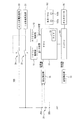
図1および図2は本発明の第1の実施形態に係る車両用電源制御装置を示す図である。
Hereinafter, embodiments of the present invention will be described in detail with reference to the drawings.
(First embodiment)
FIG. 1 and FIG. 2 are views showing a vehicle power supply control device according to the first embodiment of the present invention.

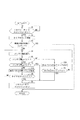
図1において、車両100は、内燃機関型のエンジン101が走行用駆動源として搭載されている。この車両100は、ECU(Electronic Control Unit)10が予め格納されている制御プログラムに従って各種パラメータに基づきエンジン101等を含む車両全体を統括制御するようになっている。ECU10は、車両100に関する各種情報を表示して報知する表示パネル102が接続されている。   In FIG. 1, a vehicle 100 is equipped with an internal combustion engine type engine 101 as a driving source for traveling. In the vehicle 100, an ECU (Electronic Control Unit) 10 performs overall control of the entire vehicle including the engine 101 and the like based on various parameters according to a control program stored in advance. The ECU 10 is connected to a display panel 102 for displaying and notifying various information related to the vehicle 100.

例えば、ECU10は、充電器として車載されているオルタネータ25を、エンジン101の駆動力(駆動エネルギ)あるいは減速時の図示しないドライブシャフトの回転力(回生エネルギ)により稼動させて、車両100に電源として搭載されている補機バッテリ20を充電するようになっている。   For example, the ECU 10 operates the alternator 25 mounted as a charger on the basis of the driving force (driving energy) of the engine 101 or the rotational force (regenerative energy) of a drive shaft (not shown) during deceleration, and serves as a power source for the vehicle 100. The auxiliary battery 20 mounted is charged.

また、車両100は、エンジン101を始動させるスタータなどを含むイグニッション(IG)系電気負荷21が補機バッテリ20にIGリレー22を介して接続されている。また、車両100は、車室内の空調をする空調装置などを含むアクセサリ(ACC)系電気負荷23が補機バッテリ20にACCリレー24を介して接続されている。   In the vehicle 100, an ignition (IG) electric load 21 including a starter for starting the engine 101 is connected to the auxiliary battery 20 via the IG relay 22. Further, in the vehicle 100, an accessory (ACC) electric load 23 including an air conditioner for air conditioning the vehicle interior is connected to the auxiliary battery 20 via the ACC relay 24.

ECU10は、IGリレー22に補機バッテリ20から受け取る電力を印加して駆動させるIGリレー駆動部11と、ACCリレー24に補機バッテリ20から受け取る電力を印加して駆動させるACCリレー駆動部12と、が接続されている。このECU10は、IGリレー駆動部11やACCリレー駆動部12を駆動させて、IGリレー22やACCリレー24により補機バッテリ20と電気負荷21、23との導通接続や導通遮断を制御するようになっている。   The ECU 10 applies an electric power received from the auxiliary battery 20 to the IG relay 22 to be driven, and an ACC relay driving part 12 applies the electric power received from the auxiliary battery 20 to the ACC relay 24 to drive the IG relay 22. , Is connected. The ECU 10 drives the IG relay driving unit 11 and the ACC relay driving unit 12 so as to control conduction connection and conduction interruption between the auxiliary battery 20 and the electric loads 21 and 23 by the IG relay 22 and the ACC relay 24. It has become.

この車両100は、図示しないイグニッションキーによりIGオン操作やACCオン操作をするようになっている。ECU10は、そのIGオン操作やACCオン操作を検出してIGリレー22やACCリレー24をオン(導通接続)状態にし、また、そのIGオフ操作やACCオフ操作を検出してIGリレー22やACCリレー24をオフ(導通遮断)状態にするようになっている。   The vehicle 100 is configured to perform an IG ON operation or an ACC ON operation with an ignition key (not shown). The ECU 10 detects the IG on operation or the ACC on operation to turn on the IG relay 22 or the ACC relay 24, and detects the IG off operation or the ACC off operation to detect the IG relay 22 or the ACC. The relay 24 is turned off (conduction interruption).

このとき、ECU10は、これらのオン操作やオフ操作に従ってIG系電気負荷21やACC系電気負荷23の稼動を制御してエンジン101などの駆動制御や停止制御を実行する。   At this time, the ECU 10 controls the operation of the IG electric load 21 and the ACC electric load 23 according to these on and off operations, and executes drive control and stop control of the engine 101 and the like.

また、ECU10は、エンジン101の出力軸の回転数を検出する回転検出部13と、補機バッテリ20の接続端子20a、20b間の電圧を検出する電圧検出部15と、が接続されている。   In addition, the ECU 10 is connected to a rotation detection unit 13 that detects the rotation speed of the output shaft of the engine 101 and a voltage detection unit 15 that detects a voltage between the connection terminals 20a and 20b of the auxiliary battery 20.

そして、ECU10は、予め格納する制御プログラムに従う各種制御処理を実行する制御部として機能するようになっている。   And ECU10 functions as a control part which performs various control processing according to a control program stored beforehand.

例えば、ECU10は、IGリレー駆動部11の駆動からIGリレー22の接続状態を検出するIG状態検出部として機能する。ECU10は、ACCリレー駆動部12の駆動からACCリレー24の接続状態を検出するACC状態検出部として機能する。また、ECU10は、回転検出部13の検出情報からエンジン101が始動して出力準備完了しているレディ状態か未回転の前準備状態かを検出するレディ状態検出部として機能する。さらに、ECU10は、電圧検出部15が検出する接続端子20a、20b間電圧から補機バッテリ20内の充電残量(SOC)を検知するSOC検知部として機能する。   For example, the ECU 10 functions as an IG state detection unit that detects the connection state of the IG relay 22 from the drive of the IG relay drive unit 11. The ECU 10 functions as an ACC state detection unit that detects the connection state of the ACC relay 24 from the drive of the ACC relay drive unit 12. Further, the ECU 10 functions as a ready state detection unit that detects whether the engine 101 is started and ready for output from the detection information of the rotation detection unit 13, or a ready state that has not yet been rotated. Further, the ECU 10 functions as an SOC detection unit that detects the remaining charge (SOC) in the auxiliary battery 20 from the voltage between the connection terminals 20a and 20b detected by the voltage detection unit 15.

このECU10は、IGリレー駆動部11によるIGリレー22の接続を検出あるいはACCリレー駆動部12によるACCリレー24の接続を検出(イグニッションキーによるIGオン操作やACCオン操作の検出でもよい)したときに、備えるタイマ機能19を起動してカウントを開始する。ECU10は、車両100が停止中で、エンジン101が稼動していないために、補機バッテリ20への充電処理が不能である状態が予め設定されているカウンタ閾値(後述する第2の制限閾値T2)を超えても継続する場合に、IGリレー22やACCリレー24をオフ状態にするようになっている。これにより、ECU10は、補機バッテリ20の充電電力が浪費されてしまうことを防止している。   The ECU 10 detects the connection of the IG relay 22 by the IG relay driving unit 11 or detects the connection of the ACC relay 24 by the ACC relay driving unit 12 (it may be an IG ON operation or an ACC ON operation detected by an ignition key). The timer function 19 provided is started to start counting. The ECU 10 has a counter threshold value (a second limit threshold value T2 to be described later) in which a state in which the charging process to the auxiliary battery 20 is not possible because the vehicle 100 is stopped and the engine 101 is not operating. ), The IG relay 22 and the ACC relay 24 are turned off. Thereby, the ECU 10 prevents the charging power of the auxiliary battery 20 from being wasted.

また、ECU10は、回転検出部13の検出情報から、エンジン101が稼働中のレディ状態(準備状態)であることを検出した場合には、電圧検出部15が検出する補機バッテリ20の電圧値に応じてオルタネータ25を駆動させることにより補機バッテリ20に充電する制御処理を実行するようになっている。ECU10は、回転検出部13の検出情報から、エンジン101が稼動する前の前準備状態であることを検出した場合には、IGリレー22やACCリレー24のオン・オフを許可または禁止する制御処理を実行するようになっている。   When the ECU 10 detects from the detection information of the rotation detector 13 that the engine 101 is in a ready state (preparation state), the voltage value of the auxiliary battery 20 detected by the voltage detector 15 is detected. In response to this, the alternator 25 is driven to execute a control process for charging the auxiliary battery 20. When the ECU 10 detects from the detection information of the rotation detection unit 13 that the engine 101 is in a pre-preparation state before the operation, the ECU 10 permits or prohibits the on / off of the IG relay 22 and the ACC relay 24. Is supposed to run.

具体的に、ECU10は、IGリレー22またはACCリレー24の接続(オン)を検出したときに、タイマ機能19を起動してIGリレー22またはACCリレー24の接続からの経過時間を計時(カウント)する。このECU10は、エンジン101のレディ状態前の前準備状態で、かつ、補機バッテリ20の電圧値が予め設定されている第1の閾値V1未満である場合、タイマ機能19によるカウントが予め設定されている第1の制限時間T1を越えたときに、IGリレー22やACCリレー24をオフ(導通遮断)状態に切り換えるようになっている。ここで、第1の閾値V1としては、例えば、エンジン101をスタータにより1回だけ始動させるのに十分な充電残量に対応する電圧値が設定されている。また、第1の制限時間T1としては、イグニッションキーのIGオン操作によりエンジン101を始動させるのに十分な3秒から5秒程度の時間が設定されている。   Specifically, when the ECU 10 detects the connection (ON) of the IG relay 22 or the ACC relay 24, the ECU 10 activates the timer function 19 to measure the elapsed time from the connection of the IG relay 22 or the ACC relay 24 (count). To do. When the ECU 101 is in a pre-preparation state before the ready state of the engine 101 and the voltage value of the auxiliary battery 20 is less than a preset first threshold value V1, the count by the timer function 19 is preset. When the first time limit T1 is exceeded, the IG relay 22 and the ACC relay 24 are switched to an off (conduction interruption) state. Here, as the first threshold value V1, for example, a voltage value corresponding to a remaining charge amount sufficient to start the engine 101 only once by the starter is set. Further, as the first time limit T1, a time of about 3 to 5 seconds sufficient to start the engine 101 by the IG on operation of the ignition key is set.

このとき、ECU10は、補機バッテリ20の電圧値が第1の閾値V1以上の場合には、タイマ機能19によるカウントが、第1の制限時間T1よりも長く予め設定されている第2の制限時間T2を越えたときに、IGリレー22やACCリレー24をオフ状態に切り換えるようになっている。ここで、第2の制限時間T2としては、例えば、乗員が不在などの状況に、補機バッテリ20の充電電力が浪費されてしまうことを防止することを目的とする時間が設定されている。   At this time, when the voltage value of the auxiliary battery 20 is equal to or higher than the first threshold value V1, the ECU 10 counts the second limit that is set in advance by the timer function 19 longer than the first limit time T1. When the time T2 is exceeded, the IG relay 22 and the ACC relay 24 are switched off. Here, the second time limit T2 is set, for example, for the purpose of preventing the charging power of the auxiliary battery 20 from being wasted in a situation where no occupant is present.

また、ECU10は、補機バッテリ20の電圧値が、第1の閾値V1よりも低く予め設定されている第2の閾値V2未満の場合には、直ちに、IGリレー22やACCリレー24をオフ(導通遮断)状態に切り換えるようになっている。ここで、第2の閾値V2としては、例えば、補機バッテリ20を再充電する復旧作業等に十分な充電残量に対応する電圧値が設定されている。   Further, when the voltage value of the auxiliary battery 20 is lower than the first threshold value V1 and less than the preset second threshold value V2, the ECU 10 immediately turns off the IG relay 22 and the ACC relay 24 ( It is designed to switch to the (conduction interruption) state. Here, as the second threshold value V <b> 2, for example, a voltage value corresponding to a remaining charge sufficient for a restoration operation for recharging the auxiliary battery 20 is set.

そして、ECU10は、図2のフローチャートに示す制御処理を制御プログラムに従って実行することにより、IGリレー22やACCリレー24の切換制御処理を行うようになっている。   And ECU10 performs the switching control process of the IG relay 22 or the ACC relay 24 by performing the control process shown in the flowchart of FIG. 2 according to a control program.

このECU10は、図2に示すように、まず、IGリレー22またはACCリレー24の接続の有無を繰り返し確認して(ステップS1)、接続状態であることを確認したときに、タイマ機能19を起動してIGリレー22やACCリレー24の接続からの経過時間のカウントを開始する(ステップS2)。   As shown in FIG. 2, the ECU 10 first repeatedly checks whether or not the IG relay 22 or the ACC relay 24 is connected (step S1), and activates the timer function 19 when it is confirmed that it is in a connected state. Then, counting of the elapsed time from the connection of the IG relay 22 and the ACC relay 24 is started (step S2).

次いで、ECU10は、エンジン101が稼働中で走行(充電)可能なレディ状態(準備状態)であるか否か確認して(ステップS3)、レディ状態であることを確認した場合にはこの制御処理を終了する。   Next, the ECU 10 confirms whether or not the engine 101 is in a ready state (preparation state) in which the engine 101 is running and can be charged (step S3). Exit.

ステップS3において、ECU10は、エンジン101がレディ状態でなく充電不能な前準備状態であることを確認した場合には、補機バッテリ20の接続端子20a、20b間の電圧値を検出し(ステップS4)、補機バッテリ20の電圧値が第1の閾値V1未満であるか否か確認する(ステップS5)。   In step S3, the ECU 10 detects the voltage value between the connection terminals 20a and 20b of the auxiliary battery 20 when confirming that the engine 101 is not in a ready state and is in a preparatory state where charging is not possible (step S4). ), It is confirmed whether the voltage value of the auxiliary battery 20 is less than the first threshold value V1 (step S5).

ステップS5において、ECU10は、補機バッテリ20の電圧値が第1の閾値V1以上である(未満でない)ことを確認した場合には、タイマ機能19によるカウントが第2の制限時間T2を越えたか否か確認して(ステップS6)、カウント時間(待機時間)が第2の制限時間T2を超えたことを確認できない場合にはステップS4に戻って同様の処理を繰り返す。   In step S5, when the ECU 10 confirms that the voltage value of the auxiliary battery 20 is equal to or greater than (not less than) the first threshold value V1, has the count by the timer function 19 exceeded the second time limit T2? If it is not confirmed (step S6) and it cannot be confirmed that the count time (standby time) exceeds the second time limit T2, the process returns to step S4 and the same processing is repeated.

ステップS6において、ECU10は、補機バッテリ20の電圧値が第1の閾値V1以上で十分な充電残量のままカウント時間が第2の制限時間T2を超えたことを確認した場合にはステップS9に進んで、IGリレー駆動部11とACCリレー駆動部12によりIGリレー22とACCリレー24をオフして、この制御処理を終了する。   In step S6, when the ECU 10 confirms that the voltage value of the auxiliary battery 20 is equal to or higher than the first threshold value V1 and the remaining charging time has exceeded the second time limit T2, the step 10 is performed. Then, the IG relay drive unit 11 and the ACC relay drive unit 12 turn off the IG relay 22 and the ACC relay 24, and this control process is terminated.

これにより、例えば、乗員が不在であるのにも拘わらず、IG系電気負荷21やACC系電気負荷23の稼動状態が維持されて補機バッテリ20の充電電力が浪費されてしまうことを未然に防止することができる。   Thereby, for example, the operating state of the IG electric load 21 and the ACC electric load 23 is maintained and the charging power of the auxiliary battery 20 is wasted in spite of the absence of a passenger. Can be prevented.

また、ステップS5において、ECU10は、補機バッテリ20の電圧値が第1の閾値V1未満であることを確認した場合には、続けて、補機バッテリ20の電圧値が第2の閾値V2未満であるか否か確認する(ステップS7)。   In step S5, when the ECU 10 confirms that the voltage value of the auxiliary battery 20 is less than the first threshold value V1, the voltage value of the auxiliary battery 20 continues to be less than the second threshold value V2. (Step S7).

ステップS7において、ECU10は、補機バッテリ20の電圧値が第2の閾値V2未満であることを確認した場合には、直ちに、ステップS9に進んで、IGリレー駆動部11とACCリレー駆動部12によりIGリレー22とACCリレー24をオフして、この制御処理を終了する。   In step S7, when the ECU 10 confirms that the voltage value of the auxiliary battery 20 is less than the second threshold value V2, the ECU 10 immediately proceeds to step S9, where the IG relay driving unit 11 and the ACC relay driving unit 12 are operated. Thus, the IG relay 22 and the ACC relay 24 are turned off, and this control process ends.

これにより、エンジン101を始動させる1回のIGオン操作を実行するだけの余裕が補機バッテリ20の充電残量にない場合には、直ちにIGリレー22やACCリレー24をオフして、補機バッテリ20が完全にバッテリ上がりの状態になってしまうことを未然に防止することができる。   As a result, when the remaining charge amount of the auxiliary battery 20 is not sufficient to perform one IG ON operation for starting the engine 101, the IG relay 22 and the ACC relay 24 are immediately turned off, and the auxiliary machine is turned off. It is possible to prevent the battery 20 from being completely discharged.

また、ステップS7において、ECU10は、補機バッテリ20の電圧値が第2の閾値V2以上である(未満でない)ことを確認した場合には、タイマ機能19によるカウントが第1の制限時間T1を越えたか否か確認して(ステップS8)、カウント時間が第1の制限時間T1を超えたことを確認できない場合にはステップS4に戻って同様の処理を繰り返す。   In step S7, when the ECU 10 confirms that the voltage value of the auxiliary battery 20 is equal to or greater than (not less than) the second threshold value V2, the count by the timer function 19 sets the first time limit T1. It is confirmed whether or not it has been exceeded (step S8), and if it cannot be confirmed that the count time has exceeded the first time limit T1, the process returns to step S4 and the same processing is repeated.

ステップS8において、ECU10は、補機バッテリ20の電圧値が第2の閾値V2以上で、カウント時間が第1の制限時間T1を超えたことを確認した場合にはステップS9に進んで、IGリレー駆動部11とACCリレー駆動部12によりIGリレー22とACCリレー24をオフして、この制御処理を終了する。   In step S8, when the ECU 10 confirms that the voltage value of the auxiliary battery 20 is greater than or equal to the second threshold value V2 and the count time exceeds the first time limit T1, the ECU 10 proceeds to step S9, and the IG relay The IG relay 22 and the ACC relay 24 are turned off by the drive unit 11 and the ACC relay drive unit 12, and this control process is terminated.

これにより、エンジン101を始動させる1回のIGオン操作を実行するだけの余裕が補機バッテリ20の充電残量にある場合には、直ちにIGリレー22やACCリレー24をオフすることなく、イグニッションキーを操作する時間だけ待機した後に、IGリレー22やACCリレー24をオフすることができる。   As a result, when the remaining charge amount of the auxiliary battery 20 is sufficient to perform one IG ON operation for starting the engine 101, the ignition is immediately turned off without turning off the IG relay 22 or the ACC relay 24. After waiting for the key operation time, the IG relay 22 and the ACC relay 24 can be turned off.

したがって、補機バッテリ20の電圧値が第1の閾値V1よりも小さく充電残量が少ない場合でも、IGリレー22やACCリレー24をオンした後に、直ちにエンジン101を始動することにより、補機バッテリ20の充電を開始することができる。また、IGリレー22やACCリレー24をオンした状態のまま放置されて補機バッテリ20が完全にバッテリ上がりの状態になってしまうことを未然に防止することができる。   Therefore, even when the voltage value of the auxiliary battery 20 is smaller than the first threshold value V1 and the remaining amount of charge is small, the auxiliary battery is started by immediately starting the engine 101 after turning on the IG relay 22 or the ACC relay 24. 20 charging can be started. Further, it is possible to prevent the auxiliary battery 20 from being left in a state where the IG relay 22 and the ACC relay 24 are turned on and being completely discharged.

このように、本実施形態のECU10は、IGリレー22やACCリレー24が接続されて、エンジン101が稼働中のレディ状態(準備状態)ないときに、補機バッテリ20の電圧値が第1の閾値V1未満である場合には、第1の制限時間T1を越えるまでは、IGオン操作の待機をした後に、IGリレー22やACCリレー24をオフする。これにより、補機バッテリ20を完全にバッテリ上がりにしてしまう前に、エンジン101を始動する操作を許容することができ、そのエンジン101の駆動により補機バッテリ20を充電することができる。   As described above, when the IG relay 22 or the ACC relay 24 is connected to the ECU 10 of the present embodiment and the engine 101 is not in a ready state (preparation state), the voltage value of the auxiliary battery 20 is the first value. If it is less than the threshold value V1, the IG relay 22 and the ACC relay 24 are turned off after waiting for the IG ON operation until the first time limit T1 is exceeded. Thereby, before the auxiliary battery 20 is completely discharged, an operation of starting the engine 101 can be permitted, and the auxiliary battery 20 can be charged by driving the engine 101.

また、補機バッテリ20の電圧値が第1の閾値V1以上の場合には、第1の制限時間T1よりも長い第2の制限時間T2を越えたときに、IGリレー22やACCリレー24をオフする。これにより、補機バッテリ20の充電電力を浪費してしまうことを未然に防止することができる。   Further, when the voltage value of the auxiliary battery 20 is equal to or higher than the first threshold value V1, the IG relay 22 and the ACC relay 24 are turned on when the second time limit T2 longer than the first time limit T1 is exceeded. Turn off. Thereby, it is possible to prevent the charging power of the auxiliary battery 20 from being wasted.

さらに、補機バッテリ20の電圧値が第1の閾値V1よりも低い第2の閾値V2未満のときには、直ちに、IGリレー22やACCリレー24をオフする。これにより、補機バッテリ20の完全なバッテリ上がりを防止して再充電などの作業を行うことができる。   Further, when the voltage value of the auxiliary battery 20 is less than the second threshold value V2 lower than the first threshold value V1, the IG relay 22 and the ACC relay 24 are immediately turned off. As a result, the auxiliary battery 20 can be prevented from being completely discharged, and operations such as recharging can be performed.

したがって、補機バッテリ20は、IGリレー22やACCリレー24をオンしたままバッテリ上がりになってしまうことを回避することができ、1回のIGオン操作など最低限の操作を許容できる充電残量がある場合には、エンジン101を始動して充電することができる。   Therefore, the auxiliary battery 20 can avoid the battery from running out with the IG relay 22 or the ACC relay 24 turned on, and the remaining charge level that allows a minimum operation such as a single IG on operation. If there is, the engine 101 can be started and charged.

(第2の実施形態)
次に、図3は本発明の第2の実施形態に係る車両用電源制御装置を示す図である。本実施形態は、上述実施形態と略同様に構成されていることから、同様な構成には同一の符号を付して図面を流用し特徴部分を説明する(以下で説明する他の実施形態も同様)。
(Second Embodiment)
Next, FIG. 3 is a diagram showing a vehicle power supply control device according to the second embodiment of the present invention. Since the present embodiment is configured in substantially the same manner as the above-described embodiment, the same reference numerals are given to the same configuration, and the features are explained using the drawings (other embodiments described below are also described). The same).

図1において、ECU10は、補機バッテリ20の電圧値が第1の閾値V1未満かつ第2の閾値V2以上である場合、表示パネル102内の消費電力が極小さい第1ランプ(報知部)102aを点灯(メッセージの表示でもよい)するようになっている。この第1ダンプ102aの点灯は、補機バッテリ20の充電のためにIGオン操作を1回だけ直ちに行う時間だけ待機した後に、IGリレー22とACCリレー24の接続を遮断する旨を報知することを意味している。   In FIG. 1, when the voltage value of the auxiliary battery 20 is less than the first threshold value V1 and greater than or equal to the second threshold value V2, the ECU 10 has a first lamp (notification unit) 102a that consumes very little power in the display panel 102. Is lit (may be a message display). The lighting of the first dump 102a informs that the connection between the IG relay 22 and the ACC relay 24 is cut off after waiting for a time to immediately perform the IG ON operation only once for charging the auxiliary battery 20. Means.

なお、ECU10は、タイマ機能19によるカウントが第1の制限時間T1を越えたとき、また、補機バッテリ20の電圧値が第2の閾値V2未満のとき、IGリレー22やACCリレー24をオフ(導通遮断)状態に切り換えて、第1ランプ102aが点灯することはない。このとき、表示パネル102には、補機バッテリ20の充電切れ(バッテリ上がり前)であるために、IG系電気負荷21やACC系電気負荷23をオフした旨を報知する第3ランプを設けて、ECU10に点灯制御を実行させるようにしてもよい。   The ECU 10 turns off the IG relay 22 and the ACC relay 24 when the count by the timer function 19 exceeds the first time limit T1 and when the voltage value of the auxiliary battery 20 is less than the second threshold value V2. The first lamp 102a is not turned on by switching to the (conduction interruption) state. At this time, the display panel 102 is provided with a third lamp for notifying that the IG electric load 21 and the ACC electric load 23 are turned off because the auxiliary battery 20 is out of charge (before the battery runs out). The ECU 10 may perform lighting control.

また、ECU10は、補機バッテリ20の電圧値が第1の閾値V1以上の場合、表示パネル102内の消費電力が極小さい第2ランプ(報知部)102bを点灯(メッセージの表示でもよい)するようになっている。この第2ランプ102bの点灯は、補機バッテリ20の充電残量は十分であるが消費されていることから、一定時間(第2の制限時間T2)待機した後にIGリレー22とACCリレー24の接続を遮断する旨を報知することを意味している。   In addition, when the voltage value of the auxiliary battery 20 is equal to or higher than the first threshold value V1, the ECU 10 turns on the second lamp (notification unit) 102b with extremely small power consumption in the display panel 102 (may display a message). It is like that. The second lamp 102b is lit because the remaining charge of the auxiliary battery 20 is sufficient but consumed, so that the IG relay 22 and the ACC relay 24 wait after a certain time (second time limit T2). It means notifying that the connection is to be cut off.

なお、ECU10は、タイマ機能19によるカウントが第2の制限時間T2を越えたとき、IGリレー22やACCリレー24をオフ(導通遮断)状態に切り換えて、第2ランプ102bが点灯することはない。このとき、表示パネル102には、補機バッテリ20の充電電力が浪費されてしまうことを防止するために、IG系電気負荷21やACC系電気負荷23をオフした旨を報知する第4ランプを設けて、ECU10に点灯制御を実行させるようにしてもよい。   When the count by the timer function 19 exceeds the second time limit T2, the ECU 10 switches the IG relay 22 and the ACC relay 24 to the off (conduction interruption) state, and the second lamp 102b does not light up. . At this time, the display panel 102 is provided with a fourth lamp for notifying that the IG electric load 21 and the ACC electric load 23 are turned off in order to prevent the charging power of the auxiliary battery 20 from being wasted. It may be provided to cause the ECU 10 to perform lighting control.

そして、ECU10は、図3のフローチャートに示すように、まず、IGリレー22またはACCリレー24の接続状態を確認したときに(ステップS1)、タイマ機能19によるその接続からの経過時間のカウントを開始する(ステップS2)。   Then, as shown in the flowchart of FIG. 3, when the ECU 10 first confirms the connection state of the IG relay 22 or the ACC relay 24 (step S1), the timer function 19 starts counting the elapsed time from the connection. (Step S2).

次いで、ECU10は、エンジン101が停止中で走行不能(充電不能)な前準備状態を確認したときに(ステップS3)、補機バッテリ20の接続端子20a、20b間の電圧値を検出し(ステップS4)、補機バッテリ20の電圧値が第1の閾値V1未満であるか否か確認する(ステップS5)。   Next, the ECU 10 detects a voltage value between the connection terminals 20a and 20b of the auxiliary battery 20 (step S3) when confirming a pre-preparation state in which the engine 101 is stopped and cannot travel (cannot be charged) (step S3). S4), it is confirmed whether the voltage value of the auxiliary battery 20 is less than the first threshold value V1 (step S5).

ステップS5において、ECU10は、補機バッテリ20の電圧値が第1の閾値V1以上である(未満でない)ことを確認した場合には、表示パネル102内の第2ランプ102bを点灯する(ステップS5A)。   In step S5, when the ECU 10 confirms that the voltage value of the auxiliary battery 20 is equal to or greater than (not less than) the first threshold value V1, the second lamp 102b in the display panel 102 is turned on (step S5A). ).

これにより、ECU10は、補機バッテリ20の充電電力を消費してIG系電気負荷21やACC系電気負荷23を稼動させていることを乗員に報知することができ、適宜、IGやACCのオフ操作を促すことができる。   As a result, the ECU 10 can notify the occupant that the IG electric load 21 and the ACC electric load 23 are in operation by consuming the charging power of the auxiliary battery 20, and turning off the IG and ACC as appropriate. The operation can be prompted.

この後に、ECU10は、補機バッテリ20の電圧値が第1の閾値V1以上で十分な充電残量のまま、タイマ機能19によるカウント時間が第2の制限時間T2を越えたことを確認した場合に(ステップS6)、ステップS9に進んでIGリレー22とACCリレー24をオフして、この制御処理を終了する。   Thereafter, the ECU 10 confirms that the count time by the timer function 19 exceeds the second time limit T2 while the voltage value of the auxiliary battery 20 is equal to or higher than the first threshold value V1 and the remaining charge amount is sufficient. (Step S6), the process proceeds to Step S9, the IG relay 22 and the ACC relay 24 are turned off, and this control process is terminated.

また、ステップS5において、ECU10は、補機バッテリ20の電圧値が第1の閾値V1未満であることを確認した後に、さらに、補機バッテリ20の電圧値が第2の閾値V2未満であることを確認した場合には(ステップS7)、直ちに、ステップS9に進んでIGリレー22とACCリレー24をオフして、この制御処理を終了する。   In step S5, after confirming that the voltage value of the auxiliary battery 20 is less than the first threshold value V1, the ECU 10 further determines that the voltage value of the auxiliary battery 20 is less than the second threshold value V2. Is confirmed (step S7), the process immediately proceeds to step S9, the IG relay 22 and the ACC relay 24 are turned off, and this control process is terminated.

さらに、ステップS5において、ECU10は、補機バッテリ20の電圧値が第1の閾値V1未満であることを確認した後に、その補機バッテリ20の電圧値が第2の閾値V2以上である(未満でない)ことを確認した場合には(ステップS7)、表示パネル102内の第1ランプ102aを点灯する(ステップS7A)。   Further, in step S5, the ECU 10 confirms that the voltage value of the auxiliary battery 20 is less than the first threshold value V1, and then the voltage value of the auxiliary battery 20 is equal to or higher than the second threshold value V2 (less than). (Step S7), the first lamp 102a in the display panel 102 is turned on (Step S7A).

これにより、ECU10は、補機バッテリ20の充電残量が直ちに充電しなければならないほど消費されて、エンジン101を始動させる1回のIGオン操作を直ちに実行するだけの時間しかないことを報知することができ、直ちに、エンジン101を始動するIGオン操作をすることを促すことができる。   As a result, the ECU 10 informs that the remaining amount of charge of the auxiliary battery 20 is consumed so that it has to be charged immediately, and that there is only time to immediately execute one IG ON operation for starting the engine 101. It is possible to promptly perform an IG-on operation for starting the engine 101.

この後に、ECU10は、補機バッテリ20の電圧値が第1の閾値未満かつ第2の閾値V2以上のまま、タイマ機能19によるカウント時間が第1の制限時間T1を越えたことを確認した場合に(ステップS8)、ステップS9に進んでIGリレー22とACCリレー24をオフして、この制御処理を終了する。   Thereafter, the ECU 10 confirms that the count value by the timer function 19 has exceeded the first time limit T1 while the voltage value of the auxiliary battery 20 remains below the first threshold value and above the second threshold value V2. (Step S8), the process proceeds to Step S9, the IG relay 22 and the ACC relay 24 are turned off, and this control process is terminated.

したがって、補機バッテリ20の充電の要否を乗員に報知して、必要な操作をすることを促すことができ、不用意に補機バッテリ20がバッテリ上がりの状態になってしまうことをより確実に回避することができる。   Therefore, it is possible to notify the occupant whether or not the auxiliary battery 20 needs to be charged, and to prompt the user to perform a necessary operation, so that the auxiliary battery 20 is more surely inadvertently put into a battery-extended state. Can be avoided.

このように、本実施形態のECU10は、上述の実施形態における作用効果に加えて、IGリレー22やACCリレー24がオンされたまま補機バッテリ20がバッテリ上がりになってしまうことをより確実に回避することができ、適宜、エンジン101の始動を促して充電することができる。   As described above, the ECU 10 of the present embodiment can more reliably prevent the auxiliary battery 20 from running out of the battery while the IG relay 22 and the ACC relay 24 are turned on in addition to the operational effects of the above-described embodiment. This can be avoided, and can be charged by prompting the engine 101 to start as appropriate.

(第3の実施形態)
次に、図4および図5は本発明の第3の実施形態に係る車両用電源制御装置を示す図である。
(Third embodiment)
Next, FIG. 4 and FIG. 5 are diagrams showing a vehicle power supply control device according to a third embodiment of the present invention.

図1において、ECU10は、エンジン101がレディ状態前の前準備状態である場合に、補機バッテリ20の電圧値に応じてIGリレー22やACCリレー24をオン状態のまま待機する第3の制限時間T3を決定するようになっている。   In FIG. 1, when the engine 101 is in the pre-preparation state before the ready state, the ECU 10 waits with the IG relay 22 and the ACC relay 24 turned on according to the voltage value of the auxiliary battery 20. Time T3 is determined.

このECU10は、図4のマップ(グラフ)に示すように、補機バッテリ20の電圧値が第1の閾値V1以上である場合には、その電圧値に応じて待機時間も長くなる第3の制限時間T3を設定する。また、ECU10は、補機バッテリ20の電圧値が第1の閾値V1以下から第2の閾値V2以上の場合には、待機時間の第3の制限時間T3として第1の制限時間T1を設定する。さらに、ECU10は、補機バッテリ20の電圧値が第2の閾値V2未満の場合には、第3の制限時間T3として待機時間なし(T3=0)を設定するようになっている。   As shown in the map (graph) in FIG. 4, when the voltage value of the auxiliary battery 20 is equal to or higher than the first threshold value V1, the ECU 10 has a third waiting time that increases according to the voltage value. A time limit T3 is set. Further, when the voltage value of the auxiliary battery 20 is not more than the first threshold value V1 and not less than the second threshold value V2, the ECU 10 sets the first limit time T1 as the third limit time T3 of the standby time. . Furthermore, when the voltage value of the auxiliary battery 20 is less than the second threshold value V2, the ECU 10 sets no standby time (T3 = 0) as the third time limit T3.

また、ECU10は、補機バッテリ20の電圧値が第1の閾値V1以上である場合の第3の制限時間T3の待機時間中には、表示パネル102内の第2ランプ102bを点灯する。このECU10は、補機バッテリ20の電圧値が第1の閾値V1以下から第2の閾値V2以上である場合の第3の制限時間T3の待機時間中には、表示パネル102内の第1ランプ102aを点灯するようになっている。   In addition, the ECU 10 lights the second lamp 102b in the display panel 102 during the standby time of the third time limit T3 when the voltage value of the auxiliary battery 20 is equal to or greater than the first threshold value V1. The ECU 10 detects the first lamp in the display panel 102 during the standby time of the third time limit T3 when the voltage value of the auxiliary battery 20 is not more than the first threshold value V1 and not less than the second threshold value V2. 102a is turned on.

そして、ECU10は、図5のフローチャートに示すように、まず、IGリレー22またはACCリレー24の接続状態を確認したときに(ステップS1)、タイマ機能19によるその接続からの経過時間のカウントを開始する(ステップS2)。   Then, as shown in the flowchart of FIG. 5, when the ECU 10 first confirms the connection state of the IG relay 22 or the ACC relay 24 (step S1), the timer function 19 starts counting the elapsed time from the connection. (Step S2).

次いで、ECU10は、エンジン101が停止中で走行不能(充電不能)な前準備状態を確認したときに(ステップS3)、補機バッテリ20の接続端子20a、20b間の電圧値を検出する(ステップS4)。   Next, the ECU 10 detects the voltage value between the connection terminals 20a and 20b of the auxiliary battery 20 when confirming the pre-preparation state in which the engine 101 is stopped and the vehicle cannot travel (cannot be charged) (step S3) (step S3). S4).

この後に、ECU10は、図4のマップを参照して、補機バッテリ20の電圧値に応じた第3の制限時間T3を設定し(ステップS11)、その第3の制限時間T3に応じて表示パネル102内の第1ランプ102aまたは第2ランプ102bの点灯、あるいは、点灯なしの制御処理を実行する(ステップS12)。   After that, the ECU 10 sets a third time limit T3 corresponding to the voltage value of the auxiliary battery 20 with reference to the map of FIG. 4 (step S11), and displays according to the third time limit T3. A control process for turning on or off the first lamp 102a or the second lamp 102b in the panel 102 is executed (step S12).

これにより、ECU10は、第1ランプ102aの点灯によりエンジン101を始動させる1回のIGオン操作を直ちに実行するだけの充電残量しか補機バッテリ20にない旨、または、第2ランプ102bの点灯により補機バッテリ20の充電残量を消費中である旨を乗員に報知することができる。   As a result, the ECU 10 indicates that the auxiliary battery 20 has only a sufficient remaining charge amount to immediately execute one IG ON operation for starting the engine 101 by the lighting of the first lamp 102a, or the lighting of the second lamp 102b. Thus, the passenger can be notified that the remaining charge of the auxiliary battery 20 is being consumed.

この後に、ECU10は、タイマ機能19によるカウント時間が第3の制限時間T3を越えたことを確認した場合に(ステップS13)、ステップS9と同様に、ステップS14に進んでIGリレー22とACCリレー24をオフして、この制御処理を終了する。   Thereafter, when the ECU 10 confirms that the count time by the timer function 19 has exceeded the third time limit T3 (step S13), the ECU 10 proceeds to step S14 as in step S9 and proceeds to the IG relay 22 and the ACC relay. 24 is turned off and the control process is terminated.

したがって、補機バッテリ20の充電残量に応じた待機時間(第3の制限時間T3)を設定することができ、その待機時間の経過前にIGやACCのオフ操作を促したり、充電切れ前にIGオン操作を促したり、補機バッテリ20の充電切れを回避することができる。   Therefore, the standby time (third time limit T3) according to the remaining charge of the auxiliary battery 20 can be set, and the IG or ACC is turned off before the standby time elapses, or before the charge is exhausted. It is possible to prompt the user to turn on the IG and to avoid the auxiliary battery 20 being out of charge.

このように、本実施形態のECU10は、上述の実施形態における作用効果に加えて、補機バッテリ20の充電残量に応じた長さで必要な操作を待機することができ、補機バッテリ20の充電の要否を乗員に報知して必要な操作を促す制御処理を簡易なステップ処理により実現することができる。   As described above, the ECU 10 according to the present embodiment can wait for a necessary operation with a length corresponding to the remaining charge amount of the auxiliary battery 20 in addition to the operational effects of the above-described embodiment. The control process for notifying the passenger of the necessity of charging and prompting the necessary operation can be realized by a simple step process.

ここで、上述の実施形態では、搭載するエンジン101の駆動により補機バッテリ20を充電する場合として、エンジン101が稼動中のレディ状態(準備状態)または停止中の前準備状態であるか否かに応じた制御処理を一例として説明するが、これに限るものではない。例えば、電気自動車やハイブリッド車のように、エンジン101の駆動に拠らずに、搭載する高電圧バッテリが高電圧リレーを介して補機バッテリに接続されて充電可能な形態の場合には、高電圧リレーの接続状態が走行可能なレディ状態(準備状態)となり、高電圧リレーの非接続状態が走行不能な前準備状態となる。このような形態でも、上述した制御処理を適用することにより、同様の作用効果を得ることができる。   Here, in the above-described embodiment, as a case where the auxiliary battery 20 is charged by driving the mounted engine 101, whether the engine 101 is in a ready state (preparation state) in operation or in a preparation state in which it is stopped. The control process according to the above will be described as an example, but the present invention is not limited to this. For example, in the case where the mounted high voltage battery is connected to the auxiliary battery via the high voltage relay and can be charged without depending on the driving of the engine 101, such as an electric vehicle or a hybrid vehicle, The connection state of the voltage relay becomes a ready state (preparation state) in which traveling is possible, and the non-connection state of the high voltage relay becomes a preparation state in which traveling is impossible. Even in such a form, the same effect can be obtained by applying the control processing described above.

本発明の実施形態を開示したが、当業者によっては本発明の範囲を逸脱することなく変更が加えられうることは明白である。すべてのこのような修正及び等価物が次の請求項に含まれることが意図されている。   While embodiments of the invention have been disclosed, it will be apparent to those skilled in the art that changes may be made without departing from the scope of the invention. All such modifications and equivalents are intended to be included in the following claims.

10 ECU(制御部)
11 IGリレー駆動部(IG状態検出部)
12 ACCリレー駆動部(ACC状態検出部)
13 回転検出部(レディ状態検出部)
15 電圧検出部
19 タイマ機能
20 補機バッテリ
20a、20b 接続端子
21 IG系電気負荷
22 IGリレー
23 ACC系電気負荷
24 ACCリレー
25 オルタネータ
100 車両
101 エンジン
102 表示パネル
102a 第1ランプ(報知部)
102b 第2ランプ(報知部)
10 ECU (control unit)
11 IG relay drive part (IG state detection part)
12 ACC relay drive unit (ACC state detection unit)
13 Rotation detector (ready state detector)
DESCRIPTION OF SYMBOLS 15 Voltage detection part 19 Timer function 20 Auxiliary battery 20a, 20b Connection terminal 21 IG system electric load 22 IG relay 23 ACC system electric load 24 ACC relay 25 Alternator 100 Vehicle 101 Engine 102 Display panel 102a First lamp (notification part)
102b Second lamp (notification unit)

Claims (3)

車両に搭載されたバッテリとユーザーの操作に応じて制御され、少なくともエンジンを始動させるためのスタータを含む電気負荷との間を接続し、または該接続を遮断するリレーを備えた車両用電源制御装置であって、
前記車両が前記エンジンの駆動力を出力可能な準備状態に移行する前の前準備状態において、前記バッテリの電圧値が第1の閾値未満である場合、前記バッテリと前記電気負荷が接続されてから前記エンジンを始動させるために要する時間である第1の制限時間が経過したときに前記バッテリと前記電気負荷との接続を遮断するよう前記リレーを制御し、前記バッテリの電圧値が前記第1の閾値以上である場合、前記バッテリと前記電気負荷が接続されてから前記第1の制限時間よりも長い第2の制限時間が経過したときに、前記バッテリと前記電気負荷との接続を遮断する制御部を備える、車両用電源制御装置。
A vehicle power supply control device including a relay mounted on a vehicle and an electric load that is controlled according to a user's operation and includes at least a starter for starting an engine , or a relay that cuts off the connection. Because
In a pre-preparation state before the vehicle shifts to a preparation state in which the driving force of the engine can be output, if the voltage value of the battery is less than a first threshold value, the battery and the electric load are connected. The relay is controlled so that the connection between the battery and the electric load is cut off when a first time limit, which is a time required for starting the engine, elapses, and the voltage value of the battery is set to the first voltage Control that cuts off the connection between the battery and the electric load when a second time limit that is longer than the first time limit elapses after the battery and the electric load are connected when the value is equal to or greater than the threshold value A vehicle power supply control device comprising a unit.
前記制御部は、前記前準備状態、かつ、前記バッテリの電圧値が前記第1の閾値よりも小さい第2の閾値未満である場合、前記バッテリと前記電気負荷との接続を遮断するよう前記リレーを制御する、請求項1に記載の車両用電源制御装置。   The control unit is configured to disconnect the connection between the battery and the electric load when the preparatory state and the voltage value of the battery are less than a second threshold value that is smaller than the first threshold value. The vehicle power supply control device according to claim 1, wherein the vehicle power supply control device is controlled. 前記第1の閾値は、前記エンジンを1度だけ始動させることが可能な前記バッテリの充電残量に対応する電圧値に設定される、請求項1または請求項2に記載の車両用電源制御装置。 Wherein the first threshold is set to a voltage value corresponding to the remaining charge amount of the battery which can be triggered only once before disappeared engine, the vehicle power supply according to claim 1 or claim 2 Control device.
JP2015162568A 2015-08-20 2015-08-20 Vehicle power supply control device Active JP6561676B2 (en)

Priority Applications (1)

Application Number Priority Date Filing Date Title
JP2015162568A JP6561676B2 (en) 2015-08-20 2015-08-20 Vehicle power supply control device

Applications Claiming Priority (1)

Application Number Priority Date Filing Date Title
JP2015162568A JP6561676B2 (en) 2015-08-20 2015-08-20 Vehicle power supply control device

Publications (2)

Publication Number Publication Date
JP2017039389A JP2017039389A (en) 2017-02-23
JP6561676B2 true JP6561676B2 (en) 2019-08-21

Family

ID=58202543

Family Applications (1)

Application Number Title Priority Date Filing Date
JP2015162568A Active JP6561676B2 (en) 2015-08-20 2015-08-20 Vehicle power supply control device

Country Status (1)

Country Link
JP (1) JP6561676B2 (en)

Families Citing this family (3)

* Cited by examiner, † Cited by third party
Publication number Priority date Publication date Assignee Title
ES2761846T3 (en) 2017-01-18 2020-05-21 Daicel Corp Method for the production of acetic acid
CN110031692B (en) * 2018-01-10 2023-07-21 厦门雅迅网络股份有限公司 Method and circuit for assisting vehicle-mounted equipment in accurately identifying ACC (active control) state
JP2020137296A (en) * 2019-02-21 2020-08-31 株式会社デンソー On-vehicle equipment power supply device

Family Cites Families (5)

* Cited by examiner, † Cited by third party
Publication number Priority date Publication date Assignee Title
US5327068A (en) * 1992-07-01 1994-07-05 Peerless Innovations, Inc. Battery protection system
JP3570665B2 (en) * 1998-05-27 2004-09-29 矢崎総業株式会社 Battery rise prevention device
JP2008018868A (en) * 2006-07-13 2008-01-31 Hitachi Ltd Vehicular power supply control device
JP5238431B2 (en) * 2008-09-26 2013-07-17 本田技研工業株式会社 Vehicle load control device
US8766472B2 (en) * 2009-11-11 2014-07-01 Volvo Construction Equipment Holding Sweden Ab Apparatus for shutting off power supply for vehicle

Also Published As

Publication number Publication date
JP2017039389A (en) 2017-02-23

Similar Documents

Publication Publication Date Title
JP6647912B2 (en) Vehicle power control method and system for jump start
KR101241226B1 (en) System of main relay monitoring for green cars and method thereof
JP6003743B2 (en) Power supply
CN111098711B (en) Vehicle with a vehicle body having a vehicle body support
JP6043394B2 (en) Vehicle control device
JP6371791B2 (en) Vehicle power supply
JP6561676B2 (en) Vehicle power supply control device
JP6669274B2 (en) Vehicle power supply system control method and vehicle power supply system
JP3925166B2 (en) Automatic engine start system
JP5907118B2 (en) Power supply system abnormality detection device
JP2017061182A (en) Vehicular control device
JP6277859B2 (en) Power control device
JP2009030598A (en) Vehicle control device
JP6561803B2 (en) High voltage controller
JP2016193631A (en) Vehicular power supply device
JP2013159202A (en) Vehicle control device
JP2004108226A (en) Engine idle stop device and engine idle stop method
JP2012178895A (en) Abnormality diagnostic device of power supply apparatus of electric motor
JP2018026900A (en) Automobile
JP2013091454A (en) Power feed system for idle stop vehicle
JP2017099197A (en) Control device of electric vehicle
JP5810905B2 (en) Motor control device
JP2017008738A (en) Engine starting device
JP2012101748A (en) Control device of electric vehicle
CN110884351A (en) Power supply device for vehicle

Legal Events

Date Code Title Description
A621 Written request for application examination

Free format text: JAPANESE INTERMEDIATE CODE: A621

Effective date: 20180306

A977 Report on retrieval

Free format text: JAPANESE INTERMEDIATE CODE: A971007

Effective date: 20181207

A131 Notification of reasons for refusal

Free format text: JAPANESE INTERMEDIATE CODE: A131

Effective date: 20181218

A521 Written amendment

Free format text: JAPANESE INTERMEDIATE CODE: A523

Effective date: 20190110

A131 Notification of reasons for refusal

Free format text: JAPANESE INTERMEDIATE CODE: A131

Effective date: 20190507

A521 Written amendment

Free format text: JAPANESE INTERMEDIATE CODE: A523

Effective date: 20190606

TRDD Decision of grant or rejection written
A01 Written decision to grant a patent or to grant a registration (utility model)

Free format text: JAPANESE INTERMEDIATE CODE: A01

Effective date: 20190625

A61 First payment of annual fees (during grant procedure)

Free format text: JAPANESE INTERMEDIATE CODE: A61

Effective date: 20190708

R151 Written notification of patent or utility model registration

Ref document number: 6561676

Country of ref document: JP

Free format text: JAPANESE INTERMEDIATE CODE: R151