JP6561385B2 - Marine damping material - Google Patents
Marine damping material Download PDFInfo
- Publication number
- JP6561385B2 JP6561385B2 JP2017198229A JP2017198229A JP6561385B2 JP 6561385 B2 JP6561385 B2 JP 6561385B2 JP 2017198229 A JP2017198229 A JP 2017198229A JP 2017198229 A JP2017198229 A JP 2017198229A JP 6561385 B2 JP6561385 B2 JP 6561385B2
- Authority
- JP
- Japan
- Prior art keywords
- damping
- layer
- filler
- layers
- polymer matrix
- Prior art date
- Legal status (The legal status is an assumption and is not a legal conclusion. Google has not performed a legal analysis and makes no representation as to the accuracy of the status listed.)
- Active
Links
- 238000013016 damping Methods 0.000 title claims description 151
- 239000000463 material Substances 0.000 title claims description 51
- 239000000945 filler Substances 0.000 claims description 75
- 239000011159 matrix material Substances 0.000 claims description 28
- 229920000642 polymer Polymers 0.000 claims description 20
- 239000000203 mixture Substances 0.000 claims description 18
- 239000004020 conductor Substances 0.000 claims description 16
- 239000003795 chemical substances by application Substances 0.000 claims description 14
- 239000000126 substance Substances 0.000 claims description 11
- 238000010030 laminating Methods 0.000 claims description 8
- 239000003822 epoxy resin Substances 0.000 claims description 7
- 229920000647 polyepoxide Polymers 0.000 claims description 7
- 239000007788 liquid Substances 0.000 claims description 6
- 238000000034 method Methods 0.000 claims description 6
- 238000004519 manufacturing process Methods 0.000 claims description 5
- 239000010410 layer Substances 0.000 description 50
- OKTJSMMVPCPJKN-UHFFFAOYSA-N Carbon Chemical compound [C] OKTJSMMVPCPJKN-UHFFFAOYSA-N 0.000 description 27
- 229910002804 graphite Inorganic materials 0.000 description 21
- 239000010439 graphite Substances 0.000 description 21
- XLOMVQKBTHCTTD-UHFFFAOYSA-N Zinc monoxide Chemical compound [Zn]=O XLOMVQKBTHCTTD-UHFFFAOYSA-N 0.000 description 18
- 230000000694 effects Effects 0.000 description 18
- FYYHWMGAXLPEAU-UHFFFAOYSA-N Magnesium Chemical compound [Mg] FYYHWMGAXLPEAU-UHFFFAOYSA-N 0.000 description 12
- 229910052749 magnesium Inorganic materials 0.000 description 12
- 239000011777 magnesium Substances 0.000 description 12
- 239000000696 magnetic material Substances 0.000 description 12
- 238000002156 mixing Methods 0.000 description 11
- 230000000052 comparative effect Effects 0.000 description 10
- 238000012360 testing method Methods 0.000 description 10
- 239000011787 zinc oxide Substances 0.000 description 8
- 239000000843 powder Substances 0.000 description 7
- 229920000620 organic polymer Polymers 0.000 description 6
- XEEYBQQBJWHFJM-UHFFFAOYSA-N Iron Chemical compound [Fe] XEEYBQQBJWHFJM-UHFFFAOYSA-N 0.000 description 5
- 229910052799 carbon Inorganic materials 0.000 description 5
- 229910052751 metal Inorganic materials 0.000 description 5
- 239000002184 metal Substances 0.000 description 5
- 229910045601 alloy Inorganic materials 0.000 description 4
- 239000000956 alloy Substances 0.000 description 4
- 239000011248 coating agent Substances 0.000 description 4
- 238000000576 coating method Methods 0.000 description 4
- 229910002113 barium titanate Inorganic materials 0.000 description 3
- JRPBQTZRNDNNOP-UHFFFAOYSA-N barium titanate Chemical compound [Ba+2].[Ba+2].[O-][Ti]([O-])([O-])[O-] JRPBQTZRNDNNOP-UHFFFAOYSA-N 0.000 description 3
- 239000002356 single layer Substances 0.000 description 3
- VILCJCGEZXAXTO-UHFFFAOYSA-N 2,2,2-tetramine Chemical compound NCCNCCNCCN VILCJCGEZXAXTO-UHFFFAOYSA-N 0.000 description 2
- PXHVJJICTQNCMI-UHFFFAOYSA-N Nickel Chemical compound [Ni] PXHVJJICTQNCMI-UHFFFAOYSA-N 0.000 description 2
- 229910052782 aluminium Inorganic materials 0.000 description 2
- XAGFODPZIPBFFR-UHFFFAOYSA-N aluminium Chemical compound [Al] XAGFODPZIPBFFR-UHFFFAOYSA-N 0.000 description 2
- 229910017052 cobalt Inorganic materials 0.000 description 2
- 239000010941 cobalt Substances 0.000 description 2
- GUTLYIVDDKVIGB-UHFFFAOYSA-N cobalt atom Chemical compound [Co] GUTLYIVDDKVIGB-UHFFFAOYSA-N 0.000 description 2
- 239000002131 composite material Substances 0.000 description 2
- 238000002847 impedance measurement Methods 0.000 description 2
- 229910052742 iron Inorganic materials 0.000 description 2
- 230000001788 irregular Effects 0.000 description 2
- 239000006247 magnetic powder Substances 0.000 description 2
- 238000005259 measurement Methods 0.000 description 2
- 239000002245 particle Substances 0.000 description 2
- LJCNRYVRMXRIQR-OLXYHTOASA-L potassium sodium L-tartrate Chemical compound [Na+].[K+].[O-]C(=O)[C@H](O)[C@@H](O)C([O-])=O LJCNRYVRMXRIQR-OLXYHTOASA-L 0.000 description 2
- 239000002994 raw material Substances 0.000 description 2
- 229920005989 resin Polymers 0.000 description 2
- 239000011347 resin Substances 0.000 description 2
- 235000011006 sodium potassium tartrate Nutrition 0.000 description 2
- 239000010936 titanium Substances 0.000 description 2
- 229910052719 titanium Inorganic materials 0.000 description 2
- 239000011701 zinc Substances 0.000 description 2
- 229910000859 α-Fe Inorganic materials 0.000 description 2
- WSMQKESQZFQMFW-UHFFFAOYSA-N 5-methyl-pyrazole-3-carboxylic acid Chemical compound CC1=CC(C(O)=O)=NN1 WSMQKESQZFQMFW-UHFFFAOYSA-N 0.000 description 1
- OYPRJOBELJOOCE-UHFFFAOYSA-N Calcium Chemical compound [Ca] OYPRJOBELJOOCE-UHFFFAOYSA-N 0.000 description 1
- 241001391944 Commicarpus scandens Species 0.000 description 1
- RYGMFSIKBFXOCR-UHFFFAOYSA-N Copper Chemical compound [Cu] RYGMFSIKBFXOCR-UHFFFAOYSA-N 0.000 description 1
- 229910052692 Dysprosium Inorganic materials 0.000 description 1
- 229910052779 Neodymium Inorganic materials 0.000 description 1
- 229910052772 Samarium Inorganic materials 0.000 description 1
- BUGBHKTXTAQXES-UHFFFAOYSA-N Selenium Chemical compound [Se] BUGBHKTXTAQXES-UHFFFAOYSA-N 0.000 description 1
- ATJFFYVFTNAWJD-UHFFFAOYSA-N Tin Chemical compound [Sn] ATJFFYVFTNAWJD-UHFFFAOYSA-N 0.000 description 1
- RTAQQCXQSZGOHL-UHFFFAOYSA-N Titanium Chemical compound [Ti] RTAQQCXQSZGOHL-UHFFFAOYSA-N 0.000 description 1
- HCHKCACWOHOZIP-UHFFFAOYSA-N Zinc Chemical compound [Zn] HCHKCACWOHOZIP-UHFFFAOYSA-N 0.000 description 1
- OEBXVKWKYKWDDA-UHFFFAOYSA-N [Ta].[Bi].[Sr] Chemical compound [Ta].[Bi].[Sr] OEBXVKWKYKWDDA-UHFFFAOYSA-N 0.000 description 1
- NSXCBNDGHHHVKT-UHFFFAOYSA-N [Ti].[Sr].[Ba] Chemical compound [Ti].[Sr].[Ba] NSXCBNDGHHHVKT-UHFFFAOYSA-N 0.000 description 1
- 230000001133 acceleration Effects 0.000 description 1
- 229910052787 antimony Inorganic materials 0.000 description 1
- WATWJIUSRGPENY-UHFFFAOYSA-N antimony atom Chemical compound [Sb] WATWJIUSRGPENY-UHFFFAOYSA-N 0.000 description 1
- LFYJSSARVMHQJB-QIXNEVBVSA-N bakuchiol Chemical compound CC(C)=CCC[C@@](C)(C=C)\C=C\C1=CC=C(O)C=C1 LFYJSSARVMHQJB-QIXNEVBVSA-N 0.000 description 1
- 229910052790 beryllium Inorganic materials 0.000 description 1
- ATBAMAFKBVZNFJ-UHFFFAOYSA-N beryllium atom Chemical compound [Be] ATBAMAFKBVZNFJ-UHFFFAOYSA-N 0.000 description 1
- 229910052797 bismuth Inorganic materials 0.000 description 1
- JCXGWMGPZLAOME-UHFFFAOYSA-N bismuth atom Chemical compound [Bi] JCXGWMGPZLAOME-UHFFFAOYSA-N 0.000 description 1
- 229910052793 cadmium Inorganic materials 0.000 description 1
- BDOSMKKIYDKNTQ-UHFFFAOYSA-N cadmium atom Chemical compound [Cd] BDOSMKKIYDKNTQ-UHFFFAOYSA-N 0.000 description 1
- 229910052791 calcium Inorganic materials 0.000 description 1
- 239000011575 calcium Substances 0.000 description 1
- 239000003153 chemical reaction reagent Substances 0.000 description 1
- 238000013329 compounding Methods 0.000 description 1
- 150000001875 compounds Chemical class 0.000 description 1
- 229910052802 copper Inorganic materials 0.000 description 1
- 239000010949 copper Substances 0.000 description 1
- KBQHZAAAGSGFKK-UHFFFAOYSA-N dysprosium atom Chemical compound [Dy] KBQHZAAAGSGFKK-UHFFFAOYSA-N 0.000 description 1
- 230000005684 electric field Effects 0.000 description 1
- 235000012438 extruded product Nutrition 0.000 description 1
- 238000009472 formulation Methods 0.000 description 1
- 230000003993 interaction Effects 0.000 description 1
- UQSXHKLRYXJYBZ-UHFFFAOYSA-N iron oxide Inorganic materials [Fe]=O UQSXHKLRYXJYBZ-UHFFFAOYSA-N 0.000 description 1
- 235000013980 iron oxide Nutrition 0.000 description 1
- VBMVTYDPPZVILR-UHFFFAOYSA-N iron(2+);oxygen(2-) Chemical class [O-2].[Fe+2] VBMVTYDPPZVILR-UHFFFAOYSA-N 0.000 description 1
- SZVJSHCCFOBDDC-UHFFFAOYSA-N iron(II,III) oxide Inorganic materials O=[Fe]O[Fe]O[Fe]=O SZVJSHCCFOBDDC-UHFFFAOYSA-N 0.000 description 1
- JEIPFZHSYJVQDO-UHFFFAOYSA-N iron(III) oxide Inorganic materials O=[Fe]O[Fe]=O JEIPFZHSYJVQDO-UHFFFAOYSA-N 0.000 description 1
- 238000003475 lamination Methods 0.000 description 1
- 239000011133 lead Substances 0.000 description 1
- GQYHUHYESMUTHG-UHFFFAOYSA-N lithium niobate Chemical compound [Li+].[O-][Nb](=O)=O GQYHUHYESMUTHG-UHFFFAOYSA-N 0.000 description 1
- 239000012762 magnetic filler Substances 0.000 description 1
- -1 magnetite Chemical class 0.000 description 1
- WPBNNNQJVZRUHP-UHFFFAOYSA-L manganese(2+);methyl n-[[2-(methoxycarbonylcarbamothioylamino)phenyl]carbamothioyl]carbamate;n-[2-(sulfidocarbothioylamino)ethyl]carbamodithioate Chemical compound [Mn+2].[S-]C(=S)NCCNC([S-])=S.COC(=O)NC(=S)NC1=CC=CC=C1NC(=S)NC(=O)OC WPBNNNQJVZRUHP-UHFFFAOYSA-L 0.000 description 1
- 150000002739 metals Chemical class 0.000 description 1
- QEFYFXOXNSNQGX-UHFFFAOYSA-N neodymium atom Chemical compound [Nd] QEFYFXOXNSNQGX-UHFFFAOYSA-N 0.000 description 1
- 229910052759 nickel Inorganic materials 0.000 description 1
- 239000003973 paint Substances 0.000 description 1
- 230000010287 polarization Effects 0.000 description 1
- 229940074439 potassium sodium tartrate Drugs 0.000 description 1
- KZUNJOHGWZRPMI-UHFFFAOYSA-N samarium atom Chemical compound [Sm] KZUNJOHGWZRPMI-UHFFFAOYSA-N 0.000 description 1
- 229910052711 selenium Inorganic materials 0.000 description 1
- 239000011669 selenium Substances 0.000 description 1
- 229910052712 strontium Inorganic materials 0.000 description 1
- CIOAGBVUUVVLOB-UHFFFAOYSA-N strontium atom Chemical compound [Sr] CIOAGBVUUVVLOB-UHFFFAOYSA-N 0.000 description 1
- VEALVRVVWBQVSL-UHFFFAOYSA-N strontium titanate Chemical compound [Sr+2].[O-][Ti]([O-])=O VEALVRVVWBQVSL-UHFFFAOYSA-N 0.000 description 1
- 229910052718 tin Inorganic materials 0.000 description 1
- 239000011135 tin Substances 0.000 description 1
- WFKWXMTUELFFGS-UHFFFAOYSA-N tungsten Chemical compound [W] WFKWXMTUELFFGS-UHFFFAOYSA-N 0.000 description 1
- 229910052721 tungsten Inorganic materials 0.000 description 1
- 239000010937 tungsten Substances 0.000 description 1
- 229910052720 vanadium Inorganic materials 0.000 description 1
- GPPXJZIENCGNKB-UHFFFAOYSA-N vanadium Chemical compound [V]#[V] GPPXJZIENCGNKB-UHFFFAOYSA-N 0.000 description 1
- 229910052725 zinc Inorganic materials 0.000 description 1
Images


Landscapes
- Laminated Bodies (AREA)
Description
本発明は、船舶用制振材、より詳細には船舶のエンジンやモーターの回転に起因する振動や騒音を防ぐために船舶エンジン固定用台盤だけでなくスクリューに動力を伝えるシャフトライナー固定用台盤等に使用してより制振効果が大きい船舶用制振材に関する。 The present invention relates to a vibration damping material for a ship, and more particularly to a shaft liner fixing base that transmits power to not only a ship engine fixing base but also a screw in order to prevent vibration and noise caused by rotation of a ship engine and motor. It is related with the vibration damping material for ships which is used for the above etc. and has a larger damping effect.
従来、先行技術文献によれば、振動や騒音を防止する手段として、自由に振動を起こさせ、その後速やかに減衰させるのがよいとする考え方があり、このような振動減衰には、振動体の有する振動エネルギーを熱に変えて消費することにより、振幅を急速に減少させ振動を止める手法が提案され、実施されている。特に、材料自体が有する減衰能を利用する制振材料が各種開発されている。例えば、非圧電性の有機高分子マトリックスに圧電性、誘電性、導電性を有する低分子化合物を分散させてなる有機高分子系制振材料が提案されている。かかる制振材料の作用は、従来の制振作用の原理とは異なる原理によるものであって、振動エネルギーを一度、電気エネルギーに変換し、次いで、熱エネルギーに変換して消費することにより振動を減衰させるものであり、圧電・導電効果に基づく電気エネルギー損失が加わるために、より効率的な振動減衰が可能とされている。 Conventionally, according to the prior art documents, as a means for preventing vibration and noise, there is an idea that it is better to cause vibration freely and then quickly attenuate it. There has been proposed and implemented a technique for rapidly reducing the amplitude and stopping the vibration by consuming the vibration energy it has into heat. In particular, various types of vibration damping materials that utilize the damping ability of the material itself have been developed. For example, an organic polymer damping material has been proposed in which a low molecular compound having piezoelectricity, dielectricity, and conductivity is dispersed in a non-piezoelectric organic polymer matrix. The action of the vibration damping material is based on a principle different from the principle of the conventional vibration damping action. The vibration energy is once converted into electric energy, then converted into heat energy and consumed. Since the electric energy loss based on the piezoelectric / conducting effect is added, more efficient vibration attenuation is possible.
しかし、前記の特許文献1に記載された複合型制振材料は、二枚の制振合金板状部材と二枚の制振合金板状部材の間に配置された有機高分子系制振層とからなり、前記有機高分子系制振層が有機高分マトリックス材料と、その中に含有される制振付与剤とからなる複合型制振材料とあり、有機高分子系制振層については、「該有機高分マトリックス材料に配合された少なくとも一種の制振付与剤とからなるシート状成形体が挙げられるが、他の形態として、互いに異なる制振付与剤を含有するシート状成形体の二層以上からなる積層体を挙げることができる。」(第0053段落)、また、塗膜形成体について、「少なくとも一種の制振制振付与剤を含有する塗料を、制振合金の接着面に塗工することにより形成されるが、互いに異なる有機高分子マトリック材料および互いに異なる制振付与剤を含有する複数の塗料を塗膜形成体が多層構造となるように順次塗工してもよい。」と、記載されている(第0054)。以上の記載から分かるように、前記2層ないし多層に含まれる制振制振付与剤は互いに機能が異なる必要があるが、制振制振付与剤を強誘電体、導電体、磁性体、のように機能ごとに分類し、異なる分類に属することを要する、とする記載は一切ない。
However, the composite vibration damping material described in
これに対して、本願発明者は、制振充填材を(A)誘電体、(B)導電体、(C)磁性体、の中の何れの機能に属するかに分類し、これら機能が異なる無機系制振付与材を組み合わせることによって従来にない制振効果を発揮することを見出して本願発明に至ったものである。組み合わせの形態としては、特に限定するものではないが、一層の中に異なる分類に属する複数の制振充填材を混合する組み合わせと、一層の中に一種類の制振充填材を含有し、その含有する制振充填材の属する種類が異なる複数の層をそれぞれ積層する組み合わせがあり、何れも制振効果は機能の違うものの組み合わせの方が効果が大きく、特に、その含有する制振充填材の属する種類が異なる複数の層をそれぞれ積層する組み合わせの方が制振効果が大きい。一層に属する制振充填材は同一種類に属する限り物質が異なる複数の制振充填材が含まれていてもかまわない。即ち、ただ単に物質が異なる制振充填材を組み合わせるのではなく、制振充填材が(A)強誘電体、(B)導電体、(C)磁性体、の中の何れに属するかに着目し、違う種類に属する制振充填材を含有する制振層を積層することによって、従来にない優れた制振効果を知見して本発明に想到したものであり、本願発明の主たる目的は、かかる優れた制振効果を備えた制振効果が大きい船舶用制振材を提供することを目的とするものである。 On the other hand, the inventor of the present application classifies the damping filler as belonging to any function among (A) dielectric, (B) conductor, and (C) magnetic substance, and these functions are different. The present invention has been found out by combining the inorganic vibration-damping imparting material with an unprecedented damping effect. The form of the combination is not particularly limited, but includes a combination in which a plurality of vibration damping fillers belonging to different classifications are mixed in one layer, and one kind of vibration damping filler in one layer. There are combinations in which a plurality of layers to which the contained damping fillers belong are laminated, each of which has a different function, but the combination is more effective, especially for the damping fillers contained. The combination of laminating a plurality of layers belonging to different types has a greater damping effect. The damping fillers belonging to one layer may include a plurality of damping fillers having different substances as long as they belong to the same type. That is, instead of simply combining damping fillers with different materials, focus on whether the damping filler belongs to (A) ferroelectric, (B) conductor, or (C) magnetic substance. And, by laminating damping layers containing damping fillers belonging to different types, the inventors have come up with the present invention by discovering an unprecedented excellent damping effect, and the main object of the present invention is An object of the present invention is to provide a marine damping material having such a great damping effect and a large damping effect.
前記の課題を解決するために、本発明は、高分子マトリックス材料中に(A)強誘電体、(B)導電体、(C)磁性体、の中の何れか異なる二種類の制振充填材をそれぞれ混合した一層の制振層からなることを特徴とする船舶用制振材とする。 In order to solve the above-mentioned problems, the present invention provides two types of vibration damping fillings that are different from any one of (A) ferroelectric, (B) conductor, and (C) magnetic substance in a polymer matrix material. It is set as the damping material for ships characterized by consisting of the one layer of damping layer which mixed each material.
また、前記の課題を解決するために、本発明は、高分子マトリックス材料中に(A)強誘電体、(B)導電体、(C)磁性体、の中の何れか異なる三種類の制振充填材をそれぞれ混合した一層の制振層からなることを特徴とする船舶用制振材とする。 In order to solve the above-mentioned problems, the present invention provides a polymer matrix material in which three different types of (A) ferroelectric, (B) conductor, and (C) magnetic substance are different. It is set as the vibration damping material for ships characterized by consisting of the vibration damping layer of each mixed with vibration filler.
また、前記の課題を解決するために、本発明は、高分子マトリックス材料中に(A)強誘電体、(B)導電体、(C)磁性体、の中の何れか一種類の制振充填材を含有する一層の制振層であって、それぞれ異なる制振充填材を含有する二層の前記制振層をそれぞれ積層し、又は、前記制振層を更に連続して複数積層してなることを特徴とする船舶用制振材とする。 In order to solve the above-mentioned problems, the present invention provides a damping material of any one of (A) a ferroelectric material, (B) a conductor, and (C) a magnetic material in a polymer matrix material. A single damping layer containing a filler, wherein each of the two damping layers containing different damping fillers is laminated, or a plurality of the damping layers are further laminated successively. It is set as the damping material for ships characterized by becoming.
また、前記の課題を解決するために、本発明は、高分子マトリックス材料中に(A)強誘電体、(B)導電体、(C)磁性体、の中の何れか一種類の制振充填材を含有する一層の制振層であって、それぞれ異なる制振充填材を含有する三層の前記制振層をそれぞれ積層し、又は、前記制振層を更に連続して複数積層してなることを特徴とする船舶用制振材とする。 In order to solve the above-mentioned problems, the present invention provides a damping material of any one of (A) a ferroelectric material, (B) a conductor, and (C) a magnetic material in a polymer matrix material. A single damping layer containing a filler, wherein each of the three damping layers containing different damping fillers is laminated, or a plurality of the damping layers are further laminated in succession. It is set as the damping material for ships characterized by becoming.
また、前記の課題を解決するために、本発明は、前記高分子マトリックス材料が硬化型エポキシ樹脂からなることを特徴とする前記の船舶用制振材とする。 In order to solve the above-described problems, the present invention provides the above-described vibration damping material for ships, wherein the polymer matrix material is made of a curable epoxy resin.
また、前記の課題を解決するために、本発明は、タテ150mm×ヨコ150mm×厚み12mmのアルミニウム製治具の中間に、タテ100mm×ヨコ100mm×厚み30mmの直方体の試験片を挟み、室温が20〜23℃、共振周波数が1000〜2000Hzの条件で、インピーダンス法に基づいて求めたダンピング比(ζ)が0.03以上となることを特徴とする前記の船舶用制振材とする。
In order to solve the above-mentioned problem, the present invention sandwiches a rectangular parallelepiped test piece of length 100 mm × width 100 mm ×
また、前記の課題を解決するために、本発明は、第1層を形成するエポキシ樹脂と制振充填材と硬化剤を含む液状組成物を成形型に注入し、次に、第2層を形成するエポキシ樹脂と制振充填材と硬化剤を含む液状組成物を前記第1層を形成する組成物が完全硬化する以前に前記第1層の組成物の表面に注入し、更に、第3層以降も同様に繰り返して各層が形成されてなることを特徴とする前記の船舶用制振材の製造方法とする。
Further, in order to solve the above-mentioned problems, the present invention injects a liquid composition containing an epoxy resin forming a first layer, a damping filler and a curing agent into a mold, A liquid composition containing an epoxy resin to be formed, a vibration-damping filler, and a curing agent is injected into the surface of the composition of the first layer before the composition for forming the first layer is completely cured. The above-described ship damping material manufacturing method is characterized in that each layer is formed in the same manner after the layers.
本願発明に係る船舶用制振材は、前記のように有機高分子マトリックス材料に制振充填材を含有する船舶用制振材において、異なる種類の制振充填材を含有する複数の制振層を積層することにより、高分子マトリックス材料に単なる制振充填材を混合しただけの従来の船舶用制振材と比較して格段に制振効果が向上する。本発明に係る船舶用制振材に使用する制振充填材は汎用品として取引されるものでよく原料コスト的にも有利である。 A marine damping material according to the present invention is a marine damping material containing a damping filler in an organic polymer matrix material as described above, and a plurality of damping layers containing different types of damping fillers. By laminating, the vibration damping effect is significantly improved as compared with the conventional marine vibration damping material in which the polymer matrix material is simply mixed with the vibration damping filler. The damping filler used in the marine damping material according to the present invention may be traded as a general-purpose product and is advantageous in terms of raw material cost.
本願発明を実施するための形態(以下「実施の形態」と称する)について、以下に詳細に説明する。しかし、本願発明は、かかる実施の形態に限定されるものではない。 Modes for carrying out the present invention (hereinafter referred to as “embodiments”) will be described in detail below. However, the present invention is not limited to such an embodiment.
本願請求の範囲第1項又は第2項の船舶用制振材は、高分子マトリックス材料中に(A)強誘電体、(B)導電体、(C)磁性体、の中の異なる何れか二種類又は三種類の制振充填材(以下「充填材」と略称する)をそれぞれ混合した一層の制振層からなることを特徴とする船舶用制振材とする。(A)強誘電体、(B)導電体、(C)磁性体、の中の異なる何れか二種類とは、(A)と(B)、(B)と(C)、(C)と(A)の中の何れかの組み合わせを言う。前記異なる何れか二種類の充填材を高分子マトリックス材料中に混合して一層の制振層を形成する。同様に、三種類の充填材とは、(A)と(B)と(C)の何れか一種類に属する三種類の充填材を言い、前記三種類の充填材を高分子マトリックス材料中に混合して一層の制振層を形成する。 The marine damping material according to claim 1 or 2 of the present application may be any one of (A) a ferroelectric material, (B) a conductor, and (C) a magnetic material in the polymer matrix material. A marine damping material comprising a single damping layer in which two or three types of damping fillers (hereinafter abbreviated as “fillers”) are mixed. (A) Ferroelectric material, (B) conductor, and (C) magnetic material, any two different types are (A) and (B), (B) and (C), (C) and Any combination in (A). Any one of the two different fillers is mixed in the polymer matrix material to form a single damping layer. Similarly, the three types of fillers refer to three types of fillers belonging to any one of (A), (B), and (C), and the three types of fillers are included in the polymer matrix material. Mix to form a single damping layer.
本願請求の範囲の第3項又は第4項の船舶用船舶用制振材は、高分子マトリックス材料中に(A)強誘電体、(B)導電体、(C)磁性体、の中の異なる一種の充填材を混合した2層ないし3層の制振層を積層した構成となる。請求項3の「前記制振層を更に連続して複数積層してなる」とは、例えば、・・(A)/(B)/(A)/(B)・・のように、(A)と(B)の2層を交互に連続して積層することを言い、(B)と(C)、(C)と(A)も同様である。更に、請求項4の場合は、(A)と(B)と(C)をこの順に限定するものではないが、例えば、・・・(A)/(B)/(C)/(A)/(B)/(C)・・・のように、(A)/(B)/(C)の順に3層を連続して積層することにより制振効果が高く好ましい。前記充填材において、(A)強誘電体、(B)導電体、(C)磁性体に属する充填材とは特に限定するものではないが、(A)強誘電体は、外から電場をかけることで分極の向きを変えられる物質を言い、例えば、チタン酸バリウム、チタン酸ストロンチウム、ニオブ酸リチウム、タンタル酸リチウム、酸化亜鉛、ロッシェル塩(酒石酸カリウムナトリウム)、BST(バリウム−ストロンチウム−チタン)、SBT(ストロンチウム−ビスマス−タンタル)、PZT(鉛−ジルコニウム−チタン)等から選択可能である。次に、(B)導電体は、前記強誘導体が電流を通さないのと対照的に電流を通す物質、例えば、グラファイト、カーボン粉末、金属粉等、当業者が周知の材料を適宜選択可能である。
The marine vibration damping material for marine vessels according to claim 3 or 4 of the claims of this application includes (A) a ferroelectric substance, (B) a conductor, and (C) a magnetic substance in a polymer matrix material. A structure in which two to three vibration damping layers in which different kinds of fillers are mixed is laminated. The phrase “consisting of a plurality of the damping layers further continuously” in
次に、(C)磁性体としては、自身の持つ磁性によって、高減衰部材中で独自に相互作用を生じて、前記高減衰部材の減衰性能を向上したり、特に低温での強度を維持したりするために機能しうる種々の磁性体からなる粉末がいずれも使用可能である。前記磁性体としては、例えばマグネタイト、マグヘマイト、フェライト、Mn−Znフェライト等の磁性酸化鉄、コバルト、ニッケル、鉄、電磁軟鉄、カルボニル鉄等の金属磁性体、前記金属と他の金属との合金や混合物等の1種または2種以上が挙げられる。また前記他の金属としては、例えばアルミニウム、コバルト、銅、鉛、マグネシウム、スズ、亜鉛、アンチモン、ベリリウム、ビスマス、カドミウム、カルシウム、マンガン、セレン、チタン、タングステン、ストロンチウム、バナジウム、ネオジム、サマリウム、ジスプロシウム等が挙げられる。 Next, (C) as a magnetic material, the magnetic properties of the magnetic material itself cause an interaction in the high damping member to improve the damping performance of the high damping member or maintain the strength particularly at low temperatures. Any powder made of various magnetic materials that can function in order to function. Examples of the magnetic material include magnetic iron oxides such as magnetite, maghemite, ferrite, and Mn-Zn ferrite, metal magnetic materials such as cobalt, nickel, iron, electromagnetic soft iron, and carbonyl iron, alloys of the metal and other metals, 1 type, or 2 or more types, such as a mixture, is mentioned. Examples of the other metal include aluminum, cobalt, copper, lead, magnesium, tin, zinc, antimony, beryllium, bismuth, cadmium, calcium, manganese, selenium, titanium, tungsten, strontium, vanadium, neodymium, samarium, dysprosium. Etc.
前記磁性体の充填材は、例えば八面体状、六面体状、球状、針状、鱗片状、不定形粒状等の種々の立体形状に形成することができる。特に異方性の小さい八面体状、六面体状、球状、不定形粒状等が好ましい。 磁性体粉は、高分子マトリックス中にできるだけ均一に分散させて、当該磁性体粉を配合することによる前記の効果をより一層向上することを考慮すると、平均粒径が2μm以下、特に1.5μm以下であるのが好ましく、0.3μm以上、特に0.5μm以上であるのが好ましい。 The magnetic filler can be formed into various three-dimensional shapes such as octahedron, hexahedron, sphere, needle, scale, and irregular shape. In particular, an octahedral shape, a hexahedral shape, a spherical shape, an irregular granular shape and the like having a small anisotropy are preferable. Considering that the magnetic powder is dispersed as uniformly as possible in the polymer matrix and further improving the above-mentioned effect by blending the magnetic powder, the average particle diameter is 2 μm or less, particularly 1.5 μm. The thickness is preferably 0.3 μm or more, particularly preferably 0.5 μm or more.
全充填材粉の配合割合は後述するとおり、特に限定するものではないが8wt%〜50wt%が好ましい。充填材粉の配合割合が前記範囲を満たさない合には、異なる充填材と充填材を併用することによるダンピング比の向上効果が得られず、高減衰部材の減衰性能が低下したりする。 The blending ratio of the total filler powder is not particularly limited as described later, but is preferably 8 wt% to 50 wt%. When the blending ratio of the filler powder does not satisfy the above range, the effect of improving the damping ratio by using different fillers and fillers cannot be obtained, and the damping performance of the high damping member is lowered.
また、逆に充填材粉の配合割合が前記範囲を超える場合には、相対的に高分子マトリックスの配合割合が少なくなりすぎるため、低温だけでなく常温でも耐久性が低下して、振動が加えられた際に割れやすくなってしまう。これに対し、充填材粉の配合割合を前記範囲内とすることで、種類の異なる充填材粉との併用によるダンピング比の向上効果により更に優れた高ダンピング比材を形成できる。 On the contrary, when the blending ratio of the filler powder exceeds the above range, the blending ratio of the polymer matrix becomes relatively small, so that the durability is lowered not only at a low temperature but also at a normal temperature, and vibration is applied. It becomes easy to break when it is done. On the other hand, by setting the blending ratio of the filler powder within the above range, a further excellent high damping ratio material can be formed due to the effect of improving the damping ratio by the combined use with different kinds of filler powder.
なお、前記ダンピング比の向上効果をより一層向上することを考慮すると、充填材の配合割合は、前記の範囲内であって特に、8wt%〜40wt%であることが好ましい。また、より高度のダンピング比の向上効果を得るには15wt%以上若しくは20wt%以上であることが好ましい。なお前記配合割合は、充填材として1種のみを使用する場合は、その充填材の配合割合であり、2種以上を併用する場合は、その合計の配合割合である。 In consideration of further improving the effect of improving the damping ratio, the blending ratio of the filler is preferably in the range described above and in particular, 8 wt% to 40 wt%. Further, in order to obtain a higher effect of improving the damping ratio, it is preferably 15 wt% or more or 20 wt% or more. The blending ratio is the blending ratio of the filler when only one kind is used as the filler, and the total blending ratio when two or more kinds are used in combination.
以下に実施例並びに比較例を挙げて本願発明について説明するが、本願発明はこれらの実施例等によって何ら限定されるものではない。 Hereinafter, the present invention will be described with reference to examples and comparative examples, but the present invention is not limited to these examples.
本実施例乃至比較例に用いる配合例を表1〜表6に示す。本実施例と比較例に用いる樹脂分は、マトリックス樹脂としてエポキシ樹脂を用いたもので、エピコート(登録商標(以下同じ)850((株)ディーアイシー製)とエピコート830((株)ディーアイシー製)を混合し、硬化剤としてTETA(トリエチレンテトラアミン)(和光純薬(株)製試薬特級)を用いて硬化してダンピング比測定の試験片を作成した。実施例1〜実施例4は制振シートの構造が1層と2層があり、1層の方は充填材が、A:強誘電体のチタン酸バリウム(TiBa)とB:導電体のグラファイト(GR)を前記エポキシ樹脂に混合して1層に形成したものであり、2層の方は、チタン酸バリウムを混合した制振層とグラファイトを混合した制振層をそれぞれ積層して2層に形成したものである。充填材の組み合わせは以下の通りである。実施例2;マグネシウム(MG)/グラファイト(GR)、実施例3;グラファイト(GR)/酸化亜鉛(ZnO)、実施例4;マグネシウム(MG)/酸化亜鉛(ZnO)。実施例5は、充填材の組み合わせが(MG)/(GR)/(ZnO)の3種類を用い、前記と同様にして1層ないし3層に形成した。 Tables 1 to 6 show formulation examples used in Examples and Comparative Examples. The resin component used in this example and the comparative example is an epoxy resin used as a matrix resin. Epicoat (registered trademark (hereinafter the same)) 850 (manufactured by DIC Corporation) and Epicoat 830 (manufactured by DIC Corporation) ) Were mixed and cured using TETA (triethylenetetraamine) (a reagent special grade manufactured by Wako Pure Chemical Industries, Ltd.) as a curing agent to prepare a specimen for measuring a damping ratio. The structure of the damping sheet has 1 layer and 2 layers. The filler is in one layer, A: Ferroelectric barium titanate (TiBa) and B: Conductor graphite (GR) in the epoxy resin The two layers are formed by laminating a damping layer mixed with barium titanate and a damping layer mixed with graphite to form two layers. The combination of materials Example 2: Magnesium (MG) / graphite (GR), Example 3: Graphite (GR) / zinc oxide (ZnO), Example 4: Magnesium (MG) / zinc oxide (ZnO). In Example 5, three types of combinations of fillers (MG) / (GR) / (ZnO) were used and formed in one to three layers in the same manner as described above.
前記の実施例1〜4記載の発明で、1層からなる発明は本願請求項1記載の発明を含む発明に該当し、同じく2層からなる発明は本願請求項3記載の2層サンドイッチタイプの発明を含む発明に該当する。実施例5記載の発明で、1層からなる発明は本願請求項2記載の発明を含む発明に該当し、同じく3層からなる発明は本願請求項4記載の3層サンドイッチタイプの発明を含む発明に該当する。また、表1記載の実施例は、配合する充填材の合計が8.2%であり、表2記載の実施例は、配合する充填材の合計が15%であり、表3記載の実施例は、配合する充填材の合計が21.4%である場合を示す。
In the inventions described in Examples 1 to 4, the invention consisting of one layer corresponds to the invention including the invention described in
次に、表4〜表6に示す比較例に係る配合例に記載の充填材は、比較対象となる実施例に用いられる充填材の種類に応じて選択される。(A)強誘電体、(B)導電体、(C)磁性体、の中の実施例に対応する何れか一種類を単独でマトリックス材料に混合し、単層に形成される。また、表4記載の比較例は、配合する充填材の合計が8.2%であり、表5記載の比較例は、配合する充填材の合計が15%であり、表6記載の比較例は、配合する充填材の合計が21.4%である場合を示す。 Next, the filler described in the blending examples according to the comparative examples shown in Tables 4 to 6 is selected according to the type of the filler used in the example to be compared. Any one of (A) ferroelectric material, (B) conductor, and (C) magnetic material corresponding to the embodiment is singly mixed with a matrix material to form a single layer. Further, in the comparative examples shown in Table 4, the total amount of fillers to be blended was 8.2%, and in the comparative examples listed in Table 5, the total of fillers to be blended was 15%. Indicates a case where the total amount of fillers to be blended is 21.4%.
なお、本実施例にて使用したグラファイト(GR)は、ジクス工業株式会社にて製造されたSIP材(水圧押し出し品)粉砕品を使用した。本粉砕品はカーボン品位が99.9%、粒径が10〜200ミクロンである。原料カーボンの製造メーカーは、東海カーボン、日本カーボン、東洋炭素である。 The graphite (GR) used in this example was a pulverized SIP material (hydraulic extruded product) manufactured by Jix Industry Co., Ltd. This ground product has a carbon quality of 99.9% and a particle size of 10 to 200 microns. The manufacturers of raw material carbon are Tokai Carbon, Nippon Carbon, and Toyo Carbon.

なお、本実施例のダンピング比の測定に用いた試験機、試験片及は試験条件は以下のとおりである。
試験機:振動試験機(エミック(株)製F−300BM)、デジタルチャージ振動計
(エミック(株)製600−B−CA6)、FFTアナライザー(アジレント 社製35670A)を使用した。
試験は千葉県産業支援技術研究所における試験機にて行った。
試験片:縦100mm×横100mm×高さ30mmの直方体エポキシ樹脂硬化物を 用いて測定した。
試料の共振周波数:1000〜2000Hz
測定温度:室温で20〜23℃
ダンピング比(ζ)は、インピーダンス測定法によって測定した。前記試験片に加速度ピックアップセンサーをセットし、錘を乗せ、前記の振動試験機(F−300BM)、デジタルチャージ振動計(600−B−CA6)、FFTアナライザー(35670A)を用いてダンピング比(ζ)を測定した。
なお、対数減衰比率(δ)よりダンピング比(ζ)及び損失係数(η)を下式により求めることができる。
ζ=δ/2π
η=2ζ=δ/π
The test conditions, test pieces, and test conditions used for measuring the damping ratio in this example are as follows.
Testing machine: Vibration testing machine (F-300BM manufactured by Emic Co., Ltd.), Digital Charge Vibrometer
(Emic Co., Ltd. 600-B-CA6) and FFT analyzer (Agilent 35670A) were used.
The test was conducted with a testing machine at the Chiba Industrial Research Institute.
Test piece: Measured by using a rectangular parallelepiped epoxy resin cured product having a length of 100 mm, a width of 100 mm, and a height of 30 mm.
Resonant frequency of sample: 1000 to 2000 Hz
Measurement temperature: 20-23 ° C. at room temperature
The damping ratio (ζ) was measured by an impedance measurement method. An acceleration pickup sensor is set on the test piece, a weight is placed thereon, and a damping ratio (ζ) is set using the vibration tester (F-300BM), digital charge vibrometer (600-B-CA6), and FFT analyzer (35670A). ) Was measured.
The damping ratio (ζ) and the loss factor (η) can be obtained from the logarithmic damping ratio (δ) by the following equations.
ζ = δ / 2π
η = 2ζ = δ / π
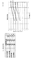
図1〜図5は、TiBa/GR系、MG/GR系、GR/ZnO系、MG/ZnO系、MG/GR/ZnO系の合計5件について2種の変量即ち前記インピーダンス測定法によって求めたダンピング比(ζ)×10の3乗(D値)と全充填材量(wt%)をそれぞれ縦軸と横軸としたグラフにそれぞれプロットし、相関関係の有無を直線で表すグラフ図である。 1 to 5 are obtained by two kinds of variables, that is, the impedance measurement method, for a total of five cases of TiBa / GR system, MG / GR system, GR / ZnO system, MG / ZnO system, and MG / GR / ZnO system. It is a graph which plots the damping ratio (ζ) × 10 to the third power (D value) and the total amount of filler (wt%) on a graph with the vertical axis and the horizontal axis, respectively, and represents the presence or absence of correlation in a straight line. .
このグラフ図から分かるように、ダンピング比と全充填材量には相関性があり、1層ごとに異なる充填材を混合した2層ないし3層の制振層を積層したことによる制振性能が向上する、いわゆる「サンドイッチ効果」が全ての実施例について顕著に見出された。 この「サンドイッチ効果」は、充填材が2種類と3種類の両系で見られるが、2種類よりも3種類系の方がダンピング比が大きい傾向が見出される。例えば、前記グラフ図5において充填材が(A)、(B)、(C)それぞれ単品からなる比較例では、充填材が8.2wt%で、ダンピング比(ζ)が0.03前後であるのに対して、(A)、(B)、(C)3種混合単一層でダンピング比(ζ)が0.055であり、(A)、(B)、(C)3層の積層品では0.064である。前者は比較例の1.8倍、後者は比較例の2.1倍の制振効果が認められる。単層で充填材複数配合系のものでは、充填材が1種類の比較例と比べると2種類ないし3種類と種類が増えるに従って、ダンピング比が大きくなる傾向が見られた。全充填材量を変量とするダンピング比のピーク値は、充填材が8.2wt%、15.0wt%、21.4wt%の3点の計測値から断定することは困難であるが、単層のグラファイト(GR)系で40wt%のダンピング比を測定したところ、ダンピング比×10の3乗(D値=33)であることから、21wt%〜40wt%の間、より挟幅視にて30wt%〜35wt%の間にピーク値が存在するとものと推定される。なお、損失係数(η)はその値が大きいほど測定材料の制振性が高いとされ、0.05以上の値であれば制振性があると判断されることから、損失係数(η)の0.05の値を、前記η=2ζに代入して、ダンピング比(ζ)=η/2=0.025が得られる。上記式からダンピング比(ζ)が0.025以上であれば制振性があると判断されることとなる。従って、請求項6に記載したダンピング比(ζ)が0.03以上であれば、より制振性に優れるものと判断される。 As can be seen from this graph, there is a correlation between the damping ratio and the total amount of filler, and the damping performance due to the lamination of two to three damping layers mixed with different fillers for each layer. An improved so-called “sandwich effect” has been found prominently for all examples. This “sandwich effect” is observed in both two and three types of fillers, but a tendency is found that the damping ratio is larger in the three types than in the two types. For example, in the comparative example in which the fillers (A), (B), and (C) in FIG. 5 are each a single product, the filler is 8.2 wt% and the damping ratio (ζ) is around 0.03. In contrast, (A), (B), and (C) a three-layer mixed single layer has a damping ratio (ζ) of 0.055, and (A), (B), and (C) a three-layer laminate. Then, it is 0.064. The former has a vibration damping effect 1.8 times that of the comparative example, and the latter 2.1 times that of the comparative example. In the case of a single layer and multiple filler compounding system, the damping ratio tended to increase as the number of fillers increased from 2 to 3 types compared to one type of comparative example. The peak value of the damping ratio with the total amount of filler as a variable is difficult to determine from the three measured values of 8.2 wt%, 15.0 wt%, and 21.4 wt% for the filler. When a damping ratio of 40 wt% was measured with a graphite (GR) system of the above, the damping ratio × 10 to the third power (D value = 33), so between 21 wt% and 40 wt%, 30 wt. It is estimated that a peak value exists between% and 35 wt%. Note that the loss factor (η) is higher as the value is larger, and the vibration damping property of the measurement material is higher. If the value is 0.05 or more, it is determined that there is a vibration damping property. Substituting the value of 0.05 into η = 2ζ, the damping ratio (ζ) = η / 2 = 0.025 is obtained. From the above formula, if the damping ratio (ζ) is 0.025 or more, it is determined that there is vibration damping. Therefore, if the damping ratio (ζ) described in claim 6 is 0.03 or more, it is determined that the damping performance is more excellent.
本願発明に係る船舶用制振材は、異なる種類の充填材を含有する複数の制振層を積層することにより、高分子マトリックス材料に単なる充填材を混合しただけの従来の船舶用制振材と比較して格段に制振効果が向上し、経済的にも有用である。
The marine damping material according to the present invention is a conventional marine damping material in which a plurality of damping layers containing different types of fillers are stacked to simply mix a polymer matrix material with a filler. Compared with, the vibration control effect is significantly improved and it is economically useful.
Claims (4)
第1層を形成する高分子マトリックス材料と制振充填材と硬化剤を含む液状組成物を成形型に注入し、次に、第2層を形成する高分子マトリックス材料と制振充填材と硬化剤を含む液状組成物を前記第1層を形成する組成物が完全硬化する以前に前記第1層の組成物の表面に注入し、各層が形成されてなることを特徴とする船舶用制振材の製造方法。 A single damping layer containing any one kind of damping filler in (A) ferroelectric, (B) conductor, (C) magnetic substance in the polymer matrix material, In the vibration damping material for a ship formed by laminating the two layers of the vibration damping layer containing different vibration damping fillers, or by laminating a plurality of the vibration damping layers in succession,
A liquid composition containing a polymer matrix material that forms the first layer, a damping filler, and a curing agent is injected into a mold, and then the polymer matrix material that forms the second layer, the damping filler, and curing. A liquid composition containing an agent is injected into the surface of the composition of the first layer before the composition forming the first layer is completely cured, and each layer is formed. A method of manufacturing the material.
第1層を形成する高分子マトリックス材料と制振充填材と硬化剤を含む液状組成物を成形型に注入し、次に、第2層を形成する高分子マトリックス材料と制振充填材と硬化剤を含む液状組成物を前記第1層を形成する組成物が完全硬化する以前に前記第1層の組成物の表面に注入し、各層が形成されてなることを特徴とする船舶用制振材の製造方法。 A single damping layer containing any one kind of damping filler in (A) ferroelectric, (B) conductor, (C) magnetic substance in the polymer matrix material, In the vibration damping material for a ship formed by laminating three layers of the vibration damping layers containing different vibration damping fillers, or by laminating a plurality of the vibration damping layers in succession,
A liquid composition containing a polymer matrix material that forms the first layer, a damping filler, and a curing agent is injected into a mold, and then the polymer matrix material that forms the second layer, the damping filler, and curing. A liquid composition containing an agent is injected into the surface of the composition of the first layer before the composition forming the first layer is completely cured, and each layer is formed. A method of manufacturing the material.
Priority Applications (1)
| Application Number | Priority Date | Filing Date | Title |
|---|---|---|---|
| JP2017198229A JP6561385B2 (en) | 2017-10-12 | 2017-10-12 | Marine damping material |
Applications Claiming Priority (1)
| Application Number | Priority Date | Filing Date | Title |
|---|---|---|---|
| JP2017198229A JP6561385B2 (en) | 2017-10-12 | 2017-10-12 | Marine damping material |
Publications (2)
| Publication Number | Publication Date |
|---|---|
| JP2019073046A JP2019073046A (en) | 2019-05-16 |
| JP6561385B2 true JP6561385B2 (en) | 2019-08-21 |
Family
ID=66544518
Family Applications (1)
| Application Number | Title | Priority Date | Filing Date |
|---|---|---|---|
| JP2017198229A Active JP6561385B2 (en) | 2017-10-12 | 2017-10-12 | Marine damping material |
Country Status (1)
| Country | Link |
|---|---|
| JP (1) | JP6561385B2 (en) |
Families Citing this family (1)
| Publication number | Priority date | Publication date | Assignee | Title |
|---|---|---|---|---|
| WO2022040386A1 (en) * | 2020-08-19 | 2022-02-24 | Basf Se | A layered liquid applied sound damper |
Family Cites Families (4)
| Publication number | Priority date | Publication date | Assignee | Title |
|---|---|---|---|---|
| JPH05318464A (en) * | 1992-05-20 | 1993-12-03 | Mitsui Eng & Shipbuild Co Ltd | Preparation of vibration-damping composite material |
| JP2011089547A (en) * | 2009-10-20 | 2011-05-06 | Nitto Denko Corp | Vibration damping sheet, method for damping vibration of vibrating member and method of using the member |
| JP2011131421A (en) * | 2009-12-22 | 2011-07-07 | Mitsubishi Electric Corp | Molding method and molding by transfer molding |
| JP2017039839A (en) * | 2015-08-19 | 2017-02-23 | 東洋インキScホールディングス株式会社 | Resin composition and method for manufacturing pearly molded body |
-
2017
- 2017-10-12 JP JP2017198229A patent/JP6561385B2/en active Active
Also Published As
| Publication number | Publication date |
|---|---|
| JP2019073046A (en) | 2019-05-16 |
Similar Documents
| Publication | Publication Date | Title |
|---|---|---|
| Martins et al. | Polymer‐based magnetoelectric materials | |
| Prateek et al. | Recent progress on ferroelectric polymer-based nanocomposites for high energy density capacitors: synthesis, dielectric properties, and future aspects | |
| Zhang et al. | Dielectric characteristics of CaCu 3 Ti 4 O 12/P (VDF-TrFE) nanocomposites | |
| Sharma et al. | PZT–PDMS composite for active damping of vibrations | |
| Mandal et al. | Improvement of magnetodielectric coupling by surface functionalization of nickel nanoparticles in Ni and polyvinylidene fluoride nanohybrids | |
| Ahn et al. | Effect of ZnO and CuO on the sintering temperature and piezoelectric properties of a hard piezoelectric ceramic | |
| US8377340B2 (en) | Electromagnetic wave suppression sheet, device, and electronic apparatus | |
| Bhadra et al. | Synthesis of PVDF/BiFeO3 nanocomposite and observation of enhanced electrical conductivity and low‐loss dielectric permittivity at percolation threshold | |
| Park et al. | Cofired magnetoelectric laminate composites | |
| JP2008021990A (en) | Electromagnetic interference suppressor and method of suppressing electromagnetic fault | |
| Palneedi et al. | Enhanced self-biased magnetoelectric coupling in laser-annealed Pb (Zr, Ti) O3 thick film deposited on Ni foil | |
| JP6561385B2 (en) | Marine damping material | |
| Srinivasan et al. | Dynamic magnetoelectric effects in bulk and layered composites of cobalt zinc ferrite and lead zirconate titanate | |
| JP5295100B2 (en) | Piezoelectric actuator having a gradient-capsule layer and method of manufacturing the piezoelectric actuator | |
| Pascariu et al. | Preparation and characterization of PbTiO3–epoxy resin compositionally graded thick films | |
| Fattah-Alhosseini et al. | Effect of particles content on microstructure, mechanical properties, and electrochemical behavior of aluminum-based hybrid composite processed by accumulative roll bonding process | |
| Mokhtari et al. | Complex magnetoelectric effect in multiferroic composites: the case of PFN-PT/(Co, Ni) Fe2O4 | |
| Fu et al. | Dielectric and energy harvesting properties of FeTiNbO6/PVDF composites with reinforced sandwich structure | |
| Kumar et al. | Epoxy-free fabrication techniques for layered/2-2 magnetoelectric composite: a review | |
| TW200921710A (en) | Dielectric compositions containing coated filler and methods relating thereto | |
| Joshi et al. | Thermally stable polyaniline and Mn0. 25Co0. 75Fe2O4 nanocomposite as an efficient material for high frequency applications at room temperature | |
| CN106427135A (en) | High-dielectric material, and preparation method and application thereof | |
| JP2010087372A (en) | Noise suppressor, noise suppressing sheet, painted goods, and manufacturing method for these | |
| Mishra et al. | Dielectric Properties of Φ (BZT‐BCT)‐(1− Φ) Epoxy Composites with 0‐3 Connectivity | |
| Atta et al. | Self-healing passivation of antimicrobial iron oxide nanoparticles for Epoxy nanocomposite coatings on carbon steel |
Legal Events
| Date | Code | Title | Description |
|---|---|---|---|
| A621 | Written request for application examination |
Free format text: JAPANESE INTERMEDIATE CODE: A621 Effective date: 20190117 |
|
| A871 | Explanation of circumstances concerning accelerated examination |
Free format text: JAPANESE INTERMEDIATE CODE: A871 Effective date: 20190117 |
|
| A975 | Report on accelerated examination |
Free format text: JAPANESE INTERMEDIATE CODE: A971005 Effective date: 20190228 |
|
| A131 | Notification of reasons for refusal |
Free format text: JAPANESE INTERMEDIATE CODE: A131 Effective date: 20190513 |
|
| A521 | Request for written amendment filed |
Free format text: JAPANESE INTERMEDIATE CODE: A523 Effective date: 20190524 |
|
| TRDD | Decision of grant or rejection written | ||
| A01 | Written decision to grant a patent or to grant a registration (utility model) |
Free format text: JAPANESE INTERMEDIATE CODE: A01 Effective date: 20190625 |
|
| A61 | First payment of annual fees (during grant procedure) |
Free format text: JAPANESE INTERMEDIATE CODE: A61 Effective date: 20190702 |
|
| R150 | Certificate of patent or registration of utility model |
Ref document number: 6561385 Country of ref document: JP Free format text: JAPANESE INTERMEDIATE CODE: R150 |
|
| R250 | Receipt of annual fees |
Free format text: JAPANESE INTERMEDIATE CODE: R250 |
|
| R250 | Receipt of annual fees |
Free format text: JAPANESE INTERMEDIATE CODE: R250 |
|
| R250 | Receipt of annual fees |
Free format text: JAPANESE INTERMEDIATE CODE: R250 |