JP2010087372A - Noise suppressor, noise suppressing sheet, painted goods, and manufacturing method for these - Google Patents
Noise suppressor, noise suppressing sheet, painted goods, and manufacturing method for these Download PDFInfo
- Publication number
- JP2010087372A JP2010087372A JP2008256700A JP2008256700A JP2010087372A JP 2010087372 A JP2010087372 A JP 2010087372A JP 2008256700 A JP2008256700 A JP 2008256700A JP 2008256700 A JP2008256700 A JP 2008256700A JP 2010087372 A JP2010087372 A JP 2010087372A
- Authority
- JP
- Japan
- Prior art keywords
- noise
- sheet
- noise suppression
- coating film
- conductive particles
- Prior art date
- Legal status (The legal status is an assumption and is not a legal conclusion. Google has not performed a legal analysis and makes no representation as to the accuracy of the status listed.)
- Granted
Links
- 238000004519 manufacturing process Methods 0.000 title claims abstract description 28
- 230000001629 suppression Effects 0.000 claims abstract description 83
- 239000002245 particle Substances 0.000 claims abstract description 65
- 239000008199 coating composition Substances 0.000 claims abstract description 23
- 239000011230 binding agent Substances 0.000 claims abstract description 19
- 238000000034 method Methods 0.000 claims abstract description 19
- 239000002904 solvent Substances 0.000 claims abstract description 14
- 238000001035 drying Methods 0.000 claims abstract description 10
- 239000011248 coating agent Substances 0.000 claims description 43
- 238000000576 coating method Methods 0.000 claims description 43
- 230000008569 process Effects 0.000 claims description 8
- 239000000835 fiber Substances 0.000 claims description 7
- 239000000843 powder Substances 0.000 claims description 5
- 239000006249 magnetic particle Substances 0.000 description 18
- 238000002156 mixing Methods 0.000 description 10
- 230000005540 biological transmission Effects 0.000 description 9
- 230000000052 comparative effect Effects 0.000 description 9
- 239000000463 material Substances 0.000 description 9
- 239000010410 layer Substances 0.000 description 8
- 229910052751 metal Inorganic materials 0.000 description 8
- 239000002184 metal Substances 0.000 description 8
- 239000011810 insulating material Substances 0.000 description 7
- 229920005989 resin Polymers 0.000 description 7
- 239000011347 resin Substances 0.000 description 7
- 239000004020 conductor Substances 0.000 description 6
- 230000005684 electric field Effects 0.000 description 6
- UQSXHKLRYXJYBZ-UHFFFAOYSA-N Iron oxide Chemical compound [Fe]=O UQSXHKLRYXJYBZ-UHFFFAOYSA-N 0.000 description 5
- 238000005516 engineering process Methods 0.000 description 5
- -1 iron aluminum silicon Chemical compound 0.000 description 5
- 239000000203 mixture Substances 0.000 description 5
- 230000005855 radiation Effects 0.000 description 5
- 239000000523 sample Substances 0.000 description 5
- XEEYBQQBJWHFJM-UHFFFAOYSA-N Iron Chemical compound [Fe] XEEYBQQBJWHFJM-UHFFFAOYSA-N 0.000 description 4
- 239000006096 absorbing agent Substances 0.000 description 4
- 239000011247 coating layer Substances 0.000 description 4
- 239000003431 cross linking reagent Substances 0.000 description 4
- 239000000696 magnetic material Substances 0.000 description 4
- 229910044991 metal oxide Inorganic materials 0.000 description 4
- 150000004706 metal oxides Chemical class 0.000 description 4
- 239000002994 raw material Substances 0.000 description 4
- 229910000859 α-Fe Inorganic materials 0.000 description 4
- OKTJSMMVPCPJKN-UHFFFAOYSA-N Carbon Chemical compound [C] OKTJSMMVPCPJKN-UHFFFAOYSA-N 0.000 description 3
- 229920000049 Carbon (fiber) Polymers 0.000 description 3
- YXFVVABEGXRONW-UHFFFAOYSA-N Toluene Chemical compound CC1=CC=CC=C1 YXFVVABEGXRONW-UHFFFAOYSA-N 0.000 description 3
- 230000002238 attenuated effect Effects 0.000 description 3
- 239000004917 carbon fiber Substances 0.000 description 3
- 239000003575 carbonaceous material Substances 0.000 description 3
- 239000000919 ceramic Substances 0.000 description 3
- 238000010586 diagram Methods 0.000 description 3
- 229920001971 elastomer Polymers 0.000 description 3
- 235000013980 iron oxide Nutrition 0.000 description 3
- 238000005259 measurement Methods 0.000 description 3
- VNWKTOKETHGBQD-UHFFFAOYSA-N methane Chemical compound C VNWKTOKETHGBQD-UHFFFAOYSA-N 0.000 description 3
- VLKZOEOYAKHREP-UHFFFAOYSA-N n-Hexane Chemical compound CCCCCC VLKZOEOYAKHREP-UHFFFAOYSA-N 0.000 description 3
- DMWVYCCGCQPJEA-UHFFFAOYSA-N 2,5-bis(tert-butylperoxy)-2,5-dimethylhexane Chemical compound CC(C)(C)OOC(C)(C)CCC(C)(C)OOC(C)(C)C DMWVYCCGCQPJEA-UHFFFAOYSA-N 0.000 description 2
- RYGMFSIKBFXOCR-UHFFFAOYSA-N Copper Chemical compound [Cu] RYGMFSIKBFXOCR-UHFFFAOYSA-N 0.000 description 2
- 239000005062 Polybutadiene Substances 0.000 description 2
- XLOMVQKBTHCTTD-UHFFFAOYSA-N Zinc monoxide Chemical compound [Zn]=O XLOMVQKBTHCTTD-UHFFFAOYSA-N 0.000 description 2
- 229910052782 aluminium Inorganic materials 0.000 description 2
- XAGFODPZIPBFFR-UHFFFAOYSA-N aluminium Chemical compound [Al] XAGFODPZIPBFFR-UHFFFAOYSA-N 0.000 description 2
- 239000003990 capacitor Substances 0.000 description 2
- 229910052799 carbon Inorganic materials 0.000 description 2
- 230000008859 change Effects 0.000 description 2
- 239000010949 copper Substances 0.000 description 2
- 238000004132 cross linking Methods 0.000 description 2
- 239000003989 dielectric material Substances 0.000 description 2
- 239000006185 dispersion Substances 0.000 description 2
- 230000000694 effects Effects 0.000 description 2
- 230000005415 magnetization Effects 0.000 description 2
- 229920002857 polybutadiene Polymers 0.000 description 2
- 238000003825 pressing Methods 0.000 description 2
- 239000005060 rubber Substances 0.000 description 2
- 239000000126 substance Substances 0.000 description 2
- 239000000758 substrate Substances 0.000 description 2
- XMNIXWIUMCBBBL-UHFFFAOYSA-N 2-(2-phenylpropan-2-ylperoxy)propan-2-ylbenzene Chemical compound C=1C=CC=CC=1C(C)(C)OOC(C)(C)C1=CC=CC=C1 XMNIXWIUMCBBBL-UHFFFAOYSA-N 0.000 description 1
- OEPOKWHJYJXUGD-UHFFFAOYSA-N 2-(3-phenylmethoxyphenyl)-1,3-thiazole-4-carbaldehyde Chemical compound O=CC1=CSC(C=2C=C(OCC=3C=CC=CC=3)C=CC=2)=N1 OEPOKWHJYJXUGD-UHFFFAOYSA-N 0.000 description 1
- PMAAOHONJPSASX-UHFFFAOYSA-N 2-butylperoxypropan-2-ylbenzene Chemical group CCCCOOC(C)(C)C1=CC=CC=C1 PMAAOHONJPSASX-UHFFFAOYSA-N 0.000 description 1
- 229920000178 Acrylic resin Polymers 0.000 description 1
- 239000004925 Acrylic resin Substances 0.000 description 1
- NLHHRLWOUZZQLW-UHFFFAOYSA-N Acrylonitrile Chemical compound C=CC#N NLHHRLWOUZZQLW-UHFFFAOYSA-N 0.000 description 1
- 241000609240 Ambelania acida Species 0.000 description 1
- 229910052582 BN Inorganic materials 0.000 description 1
- 235000017166 Bambusa arundinacea Nutrition 0.000 description 1
- 235000017491 Bambusa tulda Nutrition 0.000 description 1
- 241001330002 Bambuseae Species 0.000 description 1
- 239000004342 Benzoyl peroxide Substances 0.000 description 1
- OMPJBNCRMGITSC-UHFFFAOYSA-N Benzoylperoxide Chemical compound C=1C=CC=CC=1C(=O)OOC(=O)C1=CC=CC=C1 OMPJBNCRMGITSC-UHFFFAOYSA-N 0.000 description 1
- ZOXJGFHDIHLPTG-UHFFFAOYSA-N Boron Chemical group [B] ZOXJGFHDIHLPTG-UHFFFAOYSA-N 0.000 description 1
- PZNSFCLAULLKQX-UHFFFAOYSA-N Boron nitride Chemical compound N#B PZNSFCLAULLKQX-UHFFFAOYSA-N 0.000 description 1
- 239000004709 Chlorinated polyethylene Substances 0.000 description 1
- 244000043261 Hevea brasiliensis Species 0.000 description 1
- 229910001030 Iron–nickel alloy Inorganic materials 0.000 description 1
- ISWSIDIOOBJBQZ-UHFFFAOYSA-N Phenol Chemical compound OC1=CC=CC=C1 ISWSIDIOOBJBQZ-UHFFFAOYSA-N 0.000 description 1
- 235000015334 Phyllostachys viridis Nutrition 0.000 description 1
- 229920001131 Pulp (paper) Polymers 0.000 description 1
- 206010037660 Pyrexia Diseases 0.000 description 1
- 229910000676 Si alloy Inorganic materials 0.000 description 1
- 229910052581 Si3N4 Inorganic materials 0.000 description 1
- VYPSYNLAJGMNEJ-UHFFFAOYSA-N Silicium dioxide Chemical compound O=[Si]=O VYPSYNLAJGMNEJ-UHFFFAOYSA-N 0.000 description 1
- BQCADISMDOOEFD-UHFFFAOYSA-N Silver Chemical compound [Ag] BQCADISMDOOEFD-UHFFFAOYSA-N 0.000 description 1
- GWEVSGVZZGPLCZ-UHFFFAOYSA-N Titan oxide Chemical compound O=[Ti]=O GWEVSGVZZGPLCZ-UHFFFAOYSA-N 0.000 description 1
- XTXRWKRVRITETP-UHFFFAOYSA-N Vinyl acetate Chemical compound CC(=O)OC=C XTXRWKRVRITETP-UHFFFAOYSA-N 0.000 description 1
- 239000011358 absorbing material Substances 0.000 description 1
- 229910045601 alloy Inorganic materials 0.000 description 1
- 239000000956 alloy Substances 0.000 description 1
- 229910000808 amorphous metal alloy Inorganic materials 0.000 description 1
- 230000003712 anti-aging effect Effects 0.000 description 1
- 239000010905 bagasse Substances 0.000 description 1
- 239000011425 bamboo Substances 0.000 description 1
- 235000019400 benzoyl peroxide Nutrition 0.000 description 1
- MTAZNLWOLGHBHU-UHFFFAOYSA-N butadiene-styrene rubber Chemical compound C=CC=C.C=CC1=CC=CC=C1 MTAZNLWOLGHBHU-UHFFFAOYSA-N 0.000 description 1
- 239000006229 carbon black Substances 0.000 description 1
- 239000011203 carbon fibre reinforced carbon Substances 0.000 description 1
- 239000002041 carbon nanotube Substances 0.000 description 1
- 229910021393 carbon nanotube Inorganic materials 0.000 description 1
- 239000012461 cellulose resin Substances 0.000 description 1
- 239000003795 chemical substances by application Substances 0.000 description 1
- 239000002131 composite material Substances 0.000 description 1
- 238000000748 compression moulding Methods 0.000 description 1
- 229910052802 copper Inorganic materials 0.000 description 1
- LSXWFXONGKSEMY-UHFFFAOYSA-N di-tert-butyl peroxide Chemical compound CC(C)(C)OOC(C)(C)C LSXWFXONGKSEMY-UHFFFAOYSA-N 0.000 description 1
- NJLLQSBAHIKGKF-UHFFFAOYSA-N dipotassium dioxido(oxo)titanium Chemical compound [K+].[K+].[O-][Ti]([O-])=O NJLLQSBAHIKGKF-UHFFFAOYSA-N 0.000 description 1
- 239000002270 dispersing agent Substances 0.000 description 1
- 239000000806 elastomer Substances 0.000 description 1
- 239000003822 epoxy resin Substances 0.000 description 1
- 238000011156 evaluation Methods 0.000 description 1
- 238000010304 firing Methods 0.000 description 1
- 239000011521 glass Substances 0.000 description 1
- PCHJSUWPFVWCPO-UHFFFAOYSA-N gold Chemical compound [Au] PCHJSUWPFVWCPO-UHFFFAOYSA-N 0.000 description 1
- 229910052737 gold Inorganic materials 0.000 description 1
- 239000010931 gold Substances 0.000 description 1
- LNEPOXFFQSENCJ-UHFFFAOYSA-N haloperidol Chemical compound C1CC(O)(C=2C=CC(Cl)=CC=2)CCN1CCCC(=O)C1=CC=C(F)C=C1 LNEPOXFFQSENCJ-UHFFFAOYSA-N 0.000 description 1
- 238000010438 heat treatment Methods 0.000 description 1
- 230000001771 impaired effect Effects 0.000 description 1
- 229910003437 indium oxide Inorganic materials 0.000 description 1
- PJXISJQVUVHSOJ-UHFFFAOYSA-N indium(iii) oxide Chemical compound [O-2].[O-2].[O-2].[In+3].[In+3] PJXISJQVUVHSOJ-UHFFFAOYSA-N 0.000 description 1
- 230000006698 induction Effects 0.000 description 1
- 238000009413 insulation Methods 0.000 description 1
- 229910052742 iron Inorganic materials 0.000 description 1
- VBMVTYDPPZVILR-UHFFFAOYSA-N iron(2+);oxygen(2-) Chemical class [O-2].[Fe+2] VBMVTYDPPZVILR-UHFFFAOYSA-N 0.000 description 1
- 238000004898 kneading Methods 0.000 description 1
- 238000003475 lamination Methods 0.000 description 1
- 239000000395 magnesium oxide Substances 0.000 description 1
- CPLXHLVBOLITMK-UHFFFAOYSA-N magnesium oxide Inorganic materials [Mg]=O CPLXHLVBOLITMK-UHFFFAOYSA-N 0.000 description 1
- AXZKOIWUVFPNLO-UHFFFAOYSA-N magnesium;oxygen(2-) Chemical compound [O-2].[Mg+2] AXZKOIWUVFPNLO-UHFFFAOYSA-N 0.000 description 1
- 229910001004 magnetic alloy Inorganic materials 0.000 description 1
- 230000007257 malfunction Effects 0.000 description 1
- 238000000691 measurement method Methods 0.000 description 1
- 229910021645 metal ion Inorganic materials 0.000 description 1
- 150000002739 metals Chemical class 0.000 description 1
- IZYBEMGNIUSSAX-UHFFFAOYSA-N methyl benzenecarboperoxoate Chemical compound COOC(=O)C1=CC=CC=C1 IZYBEMGNIUSSAX-UHFFFAOYSA-N 0.000 description 1
- 238000012986 modification Methods 0.000 description 1
- 230000004048 modification Effects 0.000 description 1
- 229920003052 natural elastomer Polymers 0.000 description 1
- 229920001194 natural rubber Polymers 0.000 description 1
- PXHVJJICTQNCMI-UHFFFAOYSA-N nickel Substances [Ni] PXHVJJICTQNCMI-UHFFFAOYSA-N 0.000 description 1
- 239000003921 oil Substances 0.000 description 1
- TWNQGVIAIRXVLR-UHFFFAOYSA-N oxo(oxoalumanyloxy)alumane Chemical compound O=[Al]O[Al]=O TWNQGVIAIRXVLR-UHFFFAOYSA-N 0.000 description 1
- 229910000889 permalloy Inorganic materials 0.000 description 1
- 230000035699 permeability Effects 0.000 description 1
- 239000000049 pigment Substances 0.000 description 1
- 239000004014 plasticizer Substances 0.000 description 1
- 229920001084 poly(chloroprene) Polymers 0.000 description 1
- 229920006122 polyamide resin Polymers 0.000 description 1
- 229920005668 polycarbonate resin Polymers 0.000 description 1
- 239000004431 polycarbonate resin Substances 0.000 description 1
- 229920000647 polyepoxide Polymers 0.000 description 1
- 229920001195 polyisoprene Polymers 0.000 description 1
- 229920005672 polyolefin resin Polymers 0.000 description 1
- 229910000702 sendust Inorganic materials 0.000 description 1
- 238000010008 shearing Methods 0.000 description 1
- HQVNEWCFYHHQES-UHFFFAOYSA-N silicon nitride Chemical compound N12[Si]34N5[Si]62N3[Si]51N64 HQVNEWCFYHHQES-UHFFFAOYSA-N 0.000 description 1
- 229910052814 silicon oxide Inorganic materials 0.000 description 1
- 229920002050 silicone resin Polymers 0.000 description 1
- 229920002379 silicone rubber Polymers 0.000 description 1
- 239000004945 silicone rubber Substances 0.000 description 1
- 229910052709 silver Inorganic materials 0.000 description 1
- 239000004332 silver Substances 0.000 description 1
- 239000006104 solid solution Substances 0.000 description 1
- 239000012798 spherical particle Substances 0.000 description 1
- 229910052596 spinel Inorganic materials 0.000 description 1
- 239000011029 spinel Substances 0.000 description 1
- 229920002803 thermoplastic polyurethane Polymers 0.000 description 1
- XOLBLPGZBRYERU-UHFFFAOYSA-N tin dioxide Chemical compound O=[Sn]=O XOLBLPGZBRYERU-UHFFFAOYSA-N 0.000 description 1
- 229910001887 tin oxide Inorganic materials 0.000 description 1
- OGIDPMRJRNCKJF-UHFFFAOYSA-N titanium oxide Inorganic materials [Ti]=O OGIDPMRJRNCKJF-UHFFFAOYSA-N 0.000 description 1
- 239000013585 weight reducing agent Substances 0.000 description 1
- 239000011701 zinc Substances 0.000 description 1
- 239000011787 zinc oxide Substances 0.000 description 1
Images
Landscapes
- Shielding Devices Or Components To Electric Or Magnetic Fields (AREA)
Abstract
Description
本発明は、ノイズ抑制体、ノイズ抑制シート、塗装物品およびこれらの製造方法に関する。詳しくは、ノイズ(不要電磁波)の発生源や伝送線路に貼付あるいは塗膜形成することなどにより、ノイズを抑制するためのノイズ抑制体、ノイズ抑制シート、塗装物品およびこれらの製造方法に関する。 The present invention relates to a noise suppression body, a noise suppression sheet, a coated article, and a method for manufacturing them. More specifically, the present invention relates to a noise suppressor, a noise suppression sheet, a coated article, and a method for manufacturing the same for suppressing noise by pasting or forming a coating film on a noise (unnecessary electromagnetic wave) source or a transmission line.
携帯電話やパーソナルコンピュータなどの高周波を利用する電子機器類が広く普及し、回路への電子部品の実装密度が飛躍的に高まってきている昨今においては、電子機器や部品、回路基板などの間で生じる電磁障害の問題が深刻化してきている。このような電磁障害の対策として、ノイズ抑制体を用いることが知られており、ノイズ発生源や伝送線路を被覆して用いられている。
上記ノイズ抑制体とは、ノイズを吸収し、熱エネルギーに変換することによって除去するものであり、電磁波を反射するだけの電磁波反射体とは区別される。
ところで、電磁波の特性は、放射源からの距離に大きく依存し、近傍界(放射源からの距離が波長λ/2πよりも近い領域)と遠方界(放射源からの距離が波長λ/2πよりも遠い領域)で大きく異なる。「ノイズ抑制体」は近傍界を対象とする吸収体であり、遠方界を対象とし、自由空間を伝わる電磁波を吸収する、電磁波吸収体とは区別される。
In recent years, electronic devices using high frequencies such as mobile phones and personal computers have become widespread, and the mounting density of electronic components on circuits has increased dramatically. The problem of the electromagnetic interference that occurs is getting worse. As a countermeasure against such an electromagnetic interference, it is known to use a noise suppressor, which is used by covering a noise generation source or a transmission line.
The noise suppression body is one that absorbs noise and removes it by converting it into thermal energy, and is distinguished from an electromagnetic wave reflector that only reflects electromagnetic waves.
By the way, the characteristics of electromagnetic waves greatly depend on the distance from the radiation source, and the near field (the region where the distance from the radiation source is closer than the wavelength λ / 2π) and the far field (the distance from the radiation source is more than the wavelength λ / 2π). Is far different). A “noise suppressor” is an absorber that targets the near field, and is distinguished from an electromagnetic wave absorber that targets the far field and absorbs electromagnetic waves transmitted through free space.
ノイズ抑制体は、シート状に成形されるのが一般的であり、パソコン、携帯電話などの電子機器内部の各種配線に流れる電流が作り出す不要電磁波の干渉の抑制や、電子機器からの不要電子波の輻射の抑制を目的として、それらの電子機器や機器内部の部品などに貼付して用いられている。なお、本発明においては、前記シート状のノイズ抑制体をノイズ抑制シートと称することとする。
電磁波は、電界波と磁界波により形成されており、電界波か磁界波のどちらか一方を減衰させればもう一方も減衰する。それ故、遠方界を対象とする電磁波吸収体の場合の材料としては、導電体、誘電体、磁性体のいずれか1種類以上が用いられている。導電体、誘電体は電界波を減衰させることにより、また、磁性体は磁界波を減衰させることにより、電磁波を減衰させるものと考えられている。
Noise suppression bodies are generally molded into a sheet, which suppresses interference of unwanted electromagnetic waves generated by various currents in electronic devices such as personal computers and mobile phones, and unwanted electronic waves from electronic devices. In order to suppress the radiation of the light, it is used by being affixed to such electronic devices or parts inside the devices. In the present invention, the sheet-like noise suppression body is referred to as a noise suppression sheet.
The electromagnetic wave is formed by an electric field wave and a magnetic field wave, and if one of the electric field wave or the magnetic field wave is attenuated, the other is also attenuated. Therefore, as the material for the electromagnetic wave absorber for the far field, one or more of a conductor, a dielectric, and a magnetic material are used. It is considered that conductors and dielectrics attenuate electromagnetic waves by attenuating electric field waves, and magnetic substances attenuate electromagnetic waves by attenuating magnetic field waves.
導電性粒子を用いた技術として、例えば、コイル状の炭素繊維片を用いた電磁波シールド複合材料が知られている(特許文献1参照)。導電性粒子と磁性粒子を併用した技術として、例えば、導電性材料であるコイル状カーボンと磁性粒子を用いた電磁波吸収材料が知られている(特許文献2参照)。
一方、ノイズ抑制体の材料としては、導電体や誘電体は使用されずに、磁性体が主として使用されている。これは、ノイズ抑制体が対象としている近傍界では、電子機器内部の各種配線に流れる電流が作り出す磁界による電界の誘導が未だ十分でなく、電界波ではなく磁界波を減衰させる手段を講じることが必要と考えられていたためである。より詳しくは、導電体や誘電体は、磁性体と違って、電界に働きかけることにより、電磁波を熱エネルギーに変換して減衰させている、というのが従来の技術常識であり、導電体、誘電体を用いたシートでは、電子機器内部の各種配線に流れる電流が作り出す近傍界における磁界波ノイズに対して、抑制能を発揮しないと考えられていたためである。
As a technique using conductive particles, for example, an electromagnetic wave shielding composite material using a coiled carbon fiber piece is known (see Patent Document 1). As a technique using both conductive particles and magnetic particles in combination, for example, an electromagnetic wave absorbing material using coiled carbon which is a conductive material and magnetic particles is known (see Patent Document 2).
On the other hand, as a material for the noise suppressor, a conductor is not used, but a magnetic substance is mainly used. This is because, in the near field targeted by the noise suppressor, induction of the electric field due to the magnetic field generated by the currents flowing in the various wirings inside the electronic device is not yet sufficient, and means to attenuate the magnetic field wave instead of the electric field wave may be taken. This is because it was considered necessary. More specifically, unlike conventional magnetic materials, electrical conductors and dielectrics are converted to thermal energy and attenuated by acting on an electric field. This is because the sheet using the body is considered not to exhibit the ability to suppress the magnetic field noise in the near field generated by the current flowing through the various wirings inside the electronic device.
前記磁性材料を用いたノイズ抑制体としては、例えば、スピネル系フェライト焼結体、六方晶フェライト焼結体の球状粒子、金属磁性体の扁平状粒子等を樹脂に混合したもの(特許文献3参照)や、鉄、鉄アルミニウム珪素合金、鉄ニッケル合金、アモルファス合金、鉄酸化物などの軟磁性体粒子を用いたもの(特許文献4参照)が知られている。
上に述べたように、近傍界におけるノイズの抑制は、従来、磁性粒子を用いたものが使われてきたが、本願出願人は、導電性粒子を用いたものであっても、表面抵抗値を10〜500Ω/□に調整することで、近傍界のノイズを抑制することができることを見出し、この技術について、先に特許出願を終えている(特願2007−086054)。なお、本願出願人は、この技術を特許出願するに際して、従来の導電性材料を用いた電磁波吸収体の表面抵抗値が5000Ω/□程度であり、前記技術において本発明者が見出した表面抵抗値の最適範囲を大きく上回っていることを確認している。
磁性粒子を用いたノイズ抑制体では約1GHzからノイズ抑制特性を発揮するが、本願出願人が先に特許出願した前記技術に基づくノイズ抑制体では、数百MHzからノイズ抑制特性を発揮する。
As described above, suppression of noise in the near field has been conventionally used using magnetic particles, but the applicant of the present application is able to suppress the surface resistance even if conductive particles are used. Has been found to be able to suppress near-field noise by adjusting the current to 10 to 500Ω / □, and a patent application has already been completed for this technique (Japanese Patent Application No. 2007-086054). The applicant of the present application, when applying for a patent for this technology, has a surface resistance value of about 5000Ω / □ of an electromagnetic wave absorber using a conventional conductive material, and the surface resistance value found by the present inventor in the above technology. It has been confirmed that it is far above the optimal range.
The noise suppression body using magnetic particles exhibits noise suppression characteristics from about 1 GHz, while the noise suppression body based on the technology previously filed by the applicant of the present application exhibits noise suppression characteristics from several hundred MHz.
本願出願人が先に特許出願した前記技術に基づくノイズ抑制体は、従来の磁性粒子を用いたノイズ抑制体よりも低周波数域のノイズを抑制することができる点で優れており、低周波数用途で好適に用いることができるが、高周波数用途の場合、メイン信号の周波数がノイズ抑制特性を発現する周波数域に含まれてしまい、ノイズだけでなくメイン信号まで抑制してしまうおそれがある。したがって、低周波数用途では本願出願人が先に出願した導電性粒子を用いたノイズ抑制体、高周波数用途では従来公知の磁性粒子を用いたノイズ抑制体、という使い分けが必要であった。
しかし、一般に磁性粒子は導電性粒子よりも高価であり、また、磁性粒子として汎用されている合金は、バインダーとの混練時におけるせん断などの影響で組成変化する場合があり、取扱いが困難である。
The noise suppressor based on the technology previously filed by the applicant of the present application is superior in that it can suppress noise in a low frequency range than a noise suppressor using conventional magnetic particles, and is used for low frequencies. However, in the case of a high frequency application, the frequency of the main signal is included in the frequency range where the noise suppression characteristic is exhibited, and there is a possibility that not only the noise but also the main signal is suppressed. Therefore, it is necessary to properly use a noise suppressor using conductive particles previously filed by the applicant of the present application for low frequency applications, and a noise suppressor using conventionally known magnetic particles for high frequency applications.
However, in general, magnetic particles are more expensive than conductive particles, and alloys that are widely used as magnetic particles may change in composition due to the effect of shearing during kneading with a binder and are difficult to handle. .
そこで、本発明の解決しようとする課題は、磁性粒子よりも安価で取扱いが容易である導電性粒子を用いて、磁性粒子を用いたノイズ抑制シートと同様のノイズ抑制特性、すなわち、高周波数からノイズ抑制能を発揮する、ノイズ抑制体、ノイズ抑制シート、塗装物品およびこれらの製造方法を提供することにある。 Therefore, the problem to be solved by the present invention is to use conductive particles that are cheaper and easier to handle than magnetic particles, and have the same noise suppression characteristics as a noise suppression sheet using magnetic particles, that is, from a high frequency. An object of the present invention is to provide a noise suppressing body, a noise suppressing sheet, a coated article, and a manufacturing method thereof that exhibit noise suppressing ability.
本発明者は、上記課題を解決するべく鋭意検討を行った。
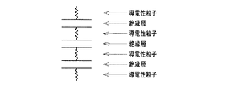
その結果、上記課題を解決するためには、非磁性の導電体粉体からなる導電性粒子が、厚み方向に隣り合う導電性粒子との間に電圧印加可能な状態で電気的絶縁層を介して多数分散していればよいことを見出した。このノイズ抑制体は、図1に示すように、抵抗とコンデンサーが交互に配置された構造になると推測され、このような構造では、周波数が大きいほど電流が流れやすくなるため、特異的に高周波数側でのノイズ抑制特性に優れるものとなると推測される。
また、前記ノイズ抑制体からなるノイズ抑制シート、塗膜が前記ノイズ抑制体である塗装物品、および、これらの好適な製造方法をも見出した。
The present inventor has intensively studied to solve the above problems.
As a result, in order to solve the above-described problem, the conductive particles made of non-magnetic conductive powder are interposed between the conductive particles adjacent to each other in the thickness direction with an electric insulating layer interposed therebetween. And found that a large number of them should be dispersed. As shown in FIG. 1, this noise suppressor is presumed to have a structure in which resistors and capacitors are alternately arranged. In such a structure, since the current is more likely to flow as the frequency increases, the noise suppressor is specifically high frequency. It is presumed that the noise suppression characteristics on the side will be excellent.
Moreover, the noise suppression sheet | seat which consists of the said noise suppression body, the coating article whose coating film is the said noise suppression body, and these suitable manufacturing methods were also discovered.
すなわち、本発明にかかるノイズ抑制体は、内部に非磁性の導電体粉体からなる導電性粒子が多数分散してなり、近傍界におけるノイズを抑制するノイズ抑制体であって、前記導電性粒子は、厚み方向に隣り合う導電性粒子との間に電圧印加可能な状態で電気的絶縁層を介して分散している、ことを特徴とする。
本発明にかかるノイズ抑制シートは、前記ノイズ抑制体からなる、ことを特徴とする。
本発明にかかるノイズ抑制シートの製造方法は、前記ノイズ抑制シートの製造方法であって、非磁性の導電性粒子、バインダーおよび溶剤からなるコーティング組成物を離型性シート上に塗布し乾燥したのち、得られた乾燥塗膜の上に前記と同一のコーティング組成物を塗布し乾燥する操作を1回以上行うことにより、離型性シート上に複層塗膜を形成し、該複層塗膜を離型性シートから剥離する、ことを特徴とする。
That is, the noise suppressor according to the present invention is a noise suppressor in which a large number of conductive particles made of non-magnetic conductive powder are dispersed therein to suppress noise in the near field, and the conductive particles Is characterized in that it is dispersed through an electrically insulating layer in a state where voltage can be applied between conductive particles adjacent in the thickness direction.
The noise suppression sheet | seat concerning this invention consists of the said noise suppression body, It is characterized by the above-mentioned.
The method for producing a noise suppression sheet according to the present invention is a method for producing the noise suppression sheet, wherein a coating composition comprising nonmagnetic conductive particles, a binder, and a solvent is applied onto a release sheet and dried. The multilayer coating film is formed on the releasable sheet by performing the operation of applying and drying the same coating composition as described above on the dried coating film, and then forming the multilayer coating film on the release sheet. Is peeled from the releasable sheet.
また、本発明にかかる塗装物品は、塗膜が前記ノイズ抑制体からなる、ことを特徴とする。
本発明にかかる塗装物品の製造方法は、前記塗装物品の製造方法であって、導電性粒子、バインダーおよび溶剤からなるコーティング組成物を被塗装物上に塗布し乾燥したのち、得られた乾燥塗膜の上に前記と同一のコーティング組成物を塗布し乾燥する操作を1回以上行うことにより、被塗装物上に複層塗膜を形成する、ことを特徴とする。
The coated article according to the present invention is characterized in that the coating film is composed of the noise suppressing body.
The method for producing a coated article according to the present invention is a method for producing the coated article, wherein a coating composition comprising conductive particles, a binder, and a solvent is applied onto an object to be coated and dried, and then the dry coating obtained is obtained. A multilayer coating film is formed on an object to be coated by performing at least one operation of applying the same coating composition on the film and drying it.
本発明にかかるノイズ抑制体、ノイズ抑制シート、塗装物品によれば、磁性粒子よりも安価で取扱いが容易である導電性粒子を用いて、磁性粒子を用いたノイズ抑制体と同様に、高周波数からノイズ抑制能を発揮させることができる。また、本発明にかかるノイズ抑制シートまたは塗装物品の製造方法によれば、前記ノイズ抑制能を発揮するノイズ抑制シートまたは塗装物品を製造することができる。 According to the noise suppressor, the noise suppression sheet, and the coated article according to the present invention, the conductive particles that are cheaper and easier to handle than the magnetic particles are used, and similarly to the noise suppressor using the magnetic particles, the high frequency Therefore, the noise suppression ability can be exhibited. Moreover, according to the manufacturing method of the noise suppression sheet | seat or coated article concerning this invention, the noise suppression sheet | seat or coated article which exhibits the said noise suppression capability can be manufactured.
以下、本発明にかかるノイズ抑制体、ノイズ抑制シート、塗装物品およびこれらの製造方法について詳しく説明するが、本発明の範囲はこれらの説明に拘束されることなく、以下の例示以外についても、本発明の趣旨を損なわない範囲で適宜変更実施し得る。
〔ノイズ抑制体〕
本発明にかかるノイズ抑制体は、内部に非磁性の導電体粉体からなる導電性粒子が多数分散してなり、近傍界におけるノイズを抑制するノイズ抑制体であって、前記導電性粒子は、厚み方向に隣り合う導電性粒子との間に電圧印加可能な状態で電気的絶縁層を介して分散している。
Hereinafter, although the noise suppression body, noise suppression sheet | seat, coated article, and these manufacturing methods concerning this invention are demonstrated in detail, the scope of the present invention is not restrained by these description, Modifications can be made as appropriate without departing from the spirit of the invention.
[Noise suppressor]
The noise suppressor according to the present invention is a noise suppressor in which a large number of conductive particles made of nonmagnetic conductive powder are dispersed therein, and suppresses noise in the near field, wherein the conductive particles are: Dispersed through the electrically insulating layer in a state where voltage can be applied between the conductive particles adjacent in the thickness direction.
<ノイズ抑制シート>
本発明にかかるノイズ抑制シートは、前記ノイズ抑制体からなる。
前記ノイズ抑制シートの厚みは、30〜3,000μmが好ましく、100〜1,000μmがより好ましい。厚みが薄いほど、小型化、軽量化することができ、電子部品の実装密度が高い回路への利用も可能となるが、薄すぎるとノイズ抑制能が十分に発現しなくなるおそれがある。
前記ノイズ抑制シートの表面抵抗値は100,000Ω/□以上であることが好ましい。より好ましくは1,000,000Ω/□以上である。ノイズ抑制シートの表面抵抗値が100,000Ω/□以上であれば、低周波数ノイズを抑制することがなく、したがって、低周波側のメイン信号を抑制してしまうこともない。また、高抵抗値のため、回路に直接貼付してもショートする心配がない。
<Noise suppression sheet>
The noise suppression sheet | seat concerning this invention consists of the said noise suppression body.
The thickness of the noise suppression sheet is preferably 30 to 3,000 μm, and more preferably 100 to 1,000 μm. The thinner the thickness, the smaller and lighter it can be, and the electronic component can be used in a circuit with a high mounting density. However, if the thickness is too thin, the noise suppression capability may not be sufficiently developed.
The surface resistance value of the noise suppression sheet is preferably 100,000Ω / □ or more. More preferably, it is 1,000,000 Ω / □ or more. If the surface resistance value of the noise suppression sheet is 100,000 Ω / □ or more, low frequency noise is not suppressed, and therefore, the main signal on the low frequency side is not suppressed. In addition, since it has a high resistance value, there is no fear of short-circuiting even if it is directly attached to the circuit.
前記ノイズ抑制シートは、小型化、軽量化が容易となる点で、その表面が平滑であることが好ましい。
<塗装物品>
本発明にかかる塗装物品は、塗膜が前記ノイズ抑制体からなる。
塗装物品の表面抵抗値は、前記ノイズ抑制シートと同様に、100,000Ω/□以上であることが好ましい。より好ましくは1,000,000Ω/□以上である。
また、塗装物品の塗膜表面は、前記ノイズ抑制シートと同様に、平滑であることが好ましい。
The noise suppression sheet preferably has a smooth surface in that it can be easily reduced in size and weight.
<Coated article>
As for the coated article concerning this invention, a coating film consists of the said noise suppression body.
The surface resistance value of the coated article is preferably 100,000 Ω / □ or more, like the noise suppression sheet. More preferably, it is 1,000,000 Ω / □ or more.
Moreover, it is preferable that the coating-film surface of a coated article is smooth similarly to the said noise suppression sheet | seat.
〔導電性粒子〕
本発明にかかるノイズ抑制体において、その内部に多数分散する導電性粒子は、非磁性の導電体粉体からなる。
ここで、非磁性とは、磁化特性を有しないこと、具体的には透磁率が1であることを意味する。
前記導電性粒子としては、特に限定するわけではないが、例えば、金属、導電性金属酸化物、炭素材料、ウィスカーなどが挙げられ、これらを1種または2種以上組み合わせて用いることができる。
[Conductive particles]
In the noise suppressor according to the present invention, a large number of conductive particles dispersed therein are made of nonmagnetic conductive powder.
Here, non-magnetic means that it has no magnetization characteristic, specifically, that the magnetic permeability is 1.
Although it does not necessarily limit as said electroconductive particle, For example, a metal, an electroconductive metal oxide, a carbon material, a whisker etc. are mentioned, These can be used 1 type or in combination of 2 or more types.
前記金属としては、特に限定するわけではないが、例えば、金、銀、銅、アルミなどが挙げられる。
前記導電性金属酸化物としては、特に限定するわけではないが、例えば、酸化亜鉛、酸化スズ、酸化インジウムなどが挙げられる。
前記炭素材料としては、特に限定するわけではないが、例えば、カーボンブラック、カーボンファイバー、カーボンナノチューブ、カーボンナノコイルなどが挙げられる。
前記ウィスカーとしては、特に限定するわけではないが、例えば、チタン酸カリウィスカーなどが挙げられる。
Although it does not necessarily limit as said metal, For example, gold | metal | money, silver, copper, aluminum etc. are mentioned.
The conductive metal oxide is not particularly limited, and examples thereof include zinc oxide, tin oxide, and indium oxide.
The carbon material is not particularly limited, and examples thereof include carbon black, carbon fiber, carbon nanotube, and carbon nanocoil.
Although it does not necessarily limit as said whisker, For example, a potassium titanate whisker etc. are mentioned.
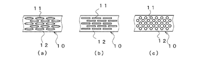
前記導電性粒子の形状としては、特に限定されず、薄片、短繊維状、球状など、種々の形状が挙げられる。特に、薄片であるか、および/または、短繊維状であれば、導電性粒子を、その長さ方向がノイズ抑制体の面方向に沿うよう配向させることができ、高周波数ノイズを安定して抑制することができるため好ましい。
具体的には、導電性粒子は、例えば、図2(a)〜(c)に示す分散状態であれば良い。図2(a)では薄片、図2(b)では短繊維状、図2(c)では球状の導電性粒子11が、絶縁層12を介して多数分散していることが分かる。
前記導電性粒子の粒子径としては、特に限定するわけではないが、例えば1〜500μmであることが好ましい。より好ましくは、10〜300μmである。1μm未満ではバインダー中への均一分散が困難になるおそれがあるとともに、粒子が小さすぎるために配向してもコンデンサー機能として寄与せず、ノイズ抑制能を充分に発揮しないおそれがある。また、500μmを超えるとノイズ抑制体の表面に凸凹、内部に空隙が発生し易くなりシート化が困難になるおそれがある。
The shape of the conductive particles is not particularly limited, and examples thereof include various shapes such as flakes, short fibers, and spheres. In particular, if it is flakes and / or short fibers, the conductive particles can be oriented so that their length direction is along the surface direction of the noise suppressor, and high frequency noise can be stabilized. Since it can suppress, it is preferable.
Specifically, the conductive particles may be in a dispersed state shown in FIGS. 2 (a) to (c), for example. It can be seen that a large number of thin conductive particles 11 are dispersed through the insulating
Although it does not necessarily limit as a particle diameter of the said electroconductive particle, For example, it is preferable that it is 1-500 micrometers. More preferably, it is 10-300 micrometers. If it is less than 1 μm, uniform dispersion in the binder may be difficult, and since the particles are too small, orientation may not contribute as a capacitor function, and noise suppression ability may not be sufficiently exhibited. On the other hand, if it exceeds 500 μm, irregularities are formed on the surface of the noise suppression body, and voids are likely to be generated inside, which may make it difficult to form a sheet.
〔絶縁層〕
絶縁層は、例えば、導電性粒子同士を結合させるバインダーとして絶縁性の材料を用いたり、各導電性粒子を絶縁コートしたりすることにより形成することができる。
前記バインダーとしては、特に限定するわけではないが、例えば、樹脂、パルプ、セラミックスなどが挙げられ、その用途や目的に応じて、その1種または2種以上を適宜選択すれば良い。
前記樹脂としては、限定するわけではないが、例えば、クロロプレンゴム、アクリルニトリル・ブタジエンゴム、スチレン・ブタジエンゴム、天然ゴム、ポリイソプレンゴムなどの各種エラストマー、ポリオレフィン樹脂、塩化ビニリデン樹脂、ポリアミド樹脂、フェノール樹脂、エポキシ樹脂、アクリル樹脂、ウレタン樹脂、シリコーン樹脂、セルロース樹脂、酢酸ビニル樹脂、ポリカーボネート樹脂などが挙げられる。
[Insulation layer]
The insulating layer can be formed, for example, by using an insulating material as a binder for bonding the conductive particles to each other, or by insulatingly coating each conductive particle.
Although it does not necessarily limit as said binder, For example, resin, a pulp, ceramics, etc. are mentioned, What is necessary is just to select the 1 type (s) or 2 or more types suitably according to the use and the objective.
Examples of the resin include, but are not limited to, various elastomers such as chloroprene rubber, acrylonitrile / butadiene rubber, styrene / butadiene rubber, natural rubber, polyisoprene rubber, polyolefin resin, vinylidene chloride resin, polyamide resin, phenol Examples thereof include resins, epoxy resins, acrylic resins, urethane resins, silicone resins, cellulose resins, vinyl acetate resins, and polycarbonate resins.
前記パルプとしては、限定するわけではないが、例えば、木材パルプ、竹パルプ、エスパルトパルプ、バガスパルプ、ボロパルプ、リンターパルプなどが挙げられる。
前記セラミックスとしては、限定するわけではないが、例えば、酸化チタン、酸化マグネシウム、酸化アルミニウム、ガラスおよびボロンナイトライド、セリサイト、酸化ケイ素、窒化ケイ素などが挙げられる。
また、各導電性粒子を絶縁コートする場合、その材料としては、前記樹脂、パルプ、セラミックスなどが挙げられるが、例えば、比較的簡易な方法として、導電性粒子として金属を用い、その表面を酸化させ、金属表面に絶縁性の酸化皮膜を形成させる方法が挙げられる。
Examples of the pulp include, but are not limited to, wood pulp, bamboo pulp, esparto pulp, bagasse pulp, boro pulp, and linter pulp.
Examples of the ceramic include, but are not limited to, titanium oxide, magnesium oxide, aluminum oxide, glass and boron nitride, sericite, silicon oxide, and silicon nitride.
In addition, when the conductive coating is applied to each conductive particle, examples of the material include the resin, pulp, and ceramic. For example, as a relatively simple method, a metal is used as the conductive particle, and the surface is oxidized. And an insulating oxide film is formed on the metal surface.
〔導電性粒子と絶縁材料の配合割合〕
上記導電性粒子と絶縁材料の配合割合は、材料の種類によって異なり一概には言えないが、例えば、導電性粒子が金属または導電性金属酸化物である場合には、その配合割合を、絶縁材料100重量部に対して50〜2,000重量部とすることが好ましい。より好ましくは100〜1,500重量部である。
導電性粒子が炭素材料である場合には、限定するわけではないが、例えば、その配合割合を、絶縁材料100重量部に対して10〜1,000重量部とすることが好ましい。より好ましくは20〜500重量部である。
[Blend ratio of conductive particles and insulating material]
The blending ratio of the conductive particles and the insulating material varies depending on the type of the material and cannot be generally specified. For example, when the conductive particles are a metal or a conductive metal oxide, the blending ratio is determined as the insulating material. It is preferable to set it as 50-2,000 weight part with respect to 100 weight part. More preferably, it is 100-1500 weight part.
In the case where the conductive particles are a carbon material, although not limited, for example, the blending ratio is preferably 10 to 1,000 parts by weight with respect to 100 parts by weight of the insulating material. More preferably, it is 20-500 weight part.
導電性粒子がウィスカーである場合には、限定するわけではないが、例えば、その配合割合を、絶縁材料100重量部に対して50〜2,000重量部とすることが好ましい。より好ましくは100〜1,500重量部である。
〔他の材料〕
本発明にかかるノイズ抑制体には、本発明の効果を害しない範囲において、他の材料を用いても良い。具体的には、例えば、磁性粒子を用いることができる。
前記磁性粒子としては、特に限定するわけではないが、例えば、磁性合金金属(センダスト、パーマロイ)やフェライトを挙げることができる。フェライトは、MO・Fe2O3なる組成をもつ一群の鉄酸化物であり、Mは2価の金属イオンで、例えば、Mn2+、Fe2+、Co2+、Ni2+、Cu2+、Zn2+などである。金属酸化物粒子と酸化鉄粒子を混合し、圧縮成形した後に焼成することにより得ることができる。Mは1種だけに限らず、2種以上を組み合わせて混合し、固溶体をつくることにより、種々の磁化特性を生じさせることもできる。例えば、平均粒径100μm以下の粒子として使用できる。磁性粒子の配合割合としては、例えば、絶縁材料100重量部に対して0〜400重量部とすることが好ましい。より好ましくは20〜200重量部である。前記磁性粒子の粒子径としては、特に限定するわけではないが、例えば、1〜300μmであることが好ましい。より好ましくは10〜200μmである。
In the case where the conductive particles are whiskers, although not limited, for example, the blending ratio is preferably 50 to 2,000 parts by weight with respect to 100 parts by weight of the insulating material. More preferably, it is 100-1500 weight part.
[Other materials]
Other materials may be used for the noise suppressor according to the present invention as long as the effects of the present invention are not impaired. Specifically, for example, magnetic particles can be used.
Examples of the magnetic particles include, but are not limited to, magnetic alloy metals (Sendust, Permalloy) and ferrite. Ferrite is a group of iron oxides having a composition of MO · Fe 2 O 3 , where M is a divalent metal ion, such as Mn 2+ , Fe 2+ , Co 2+ , Ni 2+ , Cu 2+ , Zn 2+, etc. It is. It can be obtained by mixing metal oxide particles and iron oxide particles, compression molding, and firing. M is not limited to one kind, and various magnetization characteristics can be generated by mixing two or more kinds in combination to form a solid solution. For example, it can be used as particles having an average particle size of 100 μm or less. For example, the blending ratio of the magnetic particles is preferably 0 to 400 parts by weight with respect to 100 parts by weight of the insulating material. More preferably, it is 20-200 weight part. Although it does not necessarily limit as a particle diameter of the said magnetic particle, For example, it is preferable that it is 1-300 micrometers. More preferably, it is 10-200 micrometers.
さらに、必要に応じて、溶剤、分散剤、可塑剤、架橋剤、老化防止剤、架橋促進剤、顔料などを1種または2種以上添加しても良い。前記架橋剤としては、例えば、2,5−ジメチル−2,5ビス(ターシャリーブチルパーオキシ)ヘキサン、ベンゾイルパーオキサイド、ジクミルパーオキサイド、ジターシャリーブチルパーオキサイド、ターシャリーブチルクミルパーオキサイド、パラメチルベンゾイルパーオキサイドなどを用いることができる。
〔ノイズ抑制シートの製造および用途〕
本発明にかかるノイズ抑制シートは、非磁性の導電性粒子、バインダーおよび溶剤からなるコーティング組成物を離型性シート上に塗布し乾燥したのち、得られた乾燥塗膜の上に前記と同一のコーティング組成物を塗布し乾燥する操作を1回以上行うことにより、離型性シート上に複層塗膜を形成し、該複層塗膜を離型性シートから剥離することにより製造することができる。
Furthermore, you may add 1 type (s) or 2 or more types as needed, a solvent, a dispersing agent, a plasticizer, a crosslinking agent, anti-aging agent, a crosslinking accelerator, a pigment. Examples of the crosslinking agent include 2,5-dimethyl-2,5-bis (tertiary butyl peroxy) hexane, benzoyl peroxide, dicumyl peroxide, ditertiary butyl peroxide, tertiary butyl cumyl peroxide, para Methyl benzoyl peroxide and the like can be used.
[Manufacture and use of noise suppression sheets]
The noise suppression sheet according to the present invention is the same as described above on the dried coating film obtained after applying a coating composition comprising non-magnetic conductive particles, a binder and a solvent on the release sheet and drying. It can be produced by forming a multilayer coating film on a releasable sheet by performing the operation of applying and drying the coating composition one or more times, and peeling the multilayer coating film from the release sheet. it can.
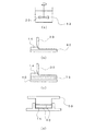
例えば、図3に示す工程(a)〜(d)を経て製造することができる。なお、図3は、模式的な図であって、その寸法比率は実際と異なる。また、工程(a)〜(d)は、本発明の一例にすぎず、例えば、工程(d)を行わなくても本発明のノイズ抑制シートを得ることはできる。
工程(a)では、非磁性の導電性粒子、バインダーおよび溶剤を、混合手段20により混合し、原料混合物13を得ている。このとき、非磁性の導電性粒子、バインダー、溶剤以外の他の原料を添加しておいても良い。
工程(b)では、前記工程(a)における混合により得られるコーティング組成物14を、塗工手段30により、離型性シート40の上に塗布している。塗工手段30としては、コーティング組成物を薄く塗り付けられるものが好ましく、例えば、ドクターブレードなどを用いる。
For example, it can be manufactured through steps (a) to (d) shown in FIG. FIG. 3 is a schematic diagram, and the dimensional ratio is different from the actual one. Moreover, process (a)-(d) is only an example of this invention, for example, even if it does not perform process (d), the noise suppression sheet | seat of this invention can be obtained.
In the step (a), nonmagnetic conductive particles, a binder and a solvent are mixed by the mixing means 20 to obtain a raw material mixture 13. At this time, raw materials other than nonmagnetic conductive particles, a binder, and a solvent may be added.
In the step (b), the
工程(c)では、前記工程(b)で得られる塗膜を乾燥して乾燥塗膜15としたのちに、さらに、塗工手段30により、コーティング組成物14を1回以上積層している。乾燥塗膜を得るための乾燥温度、乾燥時間は特に限定されないが、例えば、常温〜50℃で2〜60分乾燥すればよい。特に限定するわけではないが、本発明の目的とするノイズ抑制特性を十分に得る観点、小型化・軽量化の観点から、コーティング組成物14の積層回数は、例えば、1〜50回とすることが好ましい。
上記工程(b)、(c)における1層当たりの厚みは、積層回数にもより、特に限定されないが、例えば、1〜500μmとすることができる。
In the step (c), after the coating film obtained in the step (b) is dried to obtain the dried coating film 15, the
Although the thickness per layer in the said process (b) and (c) is not specifically limited by the frequency | count of lamination | stacking, For example, it can be set to 1-500 micrometers.
工程(d)では、前記工程(c)で得られる複層塗膜16を加圧手段50により加圧している。加圧する際には、複層塗膜16と加圧手段50の粘着を避けるために、複層塗膜上に離型性シート40を載せている。この工程(d)を行うことにより、さらなる薄膜化が可能となる。また、原料として架橋剤を用いていれば、この工程(d)の際に熱を加えることで、加圧とともに架橋も行うことができる。架橋を行うことで、得られるノイズ抑制シートの強度が高まる。加える圧力は、例えば、1〜200MPaとすることができ、さらに加熱も行う場合には、その温度を60〜250℃とすることができる。
前記工程(a)〜(d)を行った後、離型性シートを剥離することで、ノイズ抑制シートを得ることができる。
In the step (d), the
After performing said process (a)-(d), a noise suppression sheet | seat can be obtained by peeling a release sheet.
非磁性の導電性粒子、バインダーについては、例えば、先に例示したものが使用できる。
前記溶剤としては、非磁性の導電性粒子およびバインダーを良好に分散あるいは溶解させるものを用いれば良く、特に限定されない。
前記ノイズ抑制シートの厚みや表面抵抗値の好適範囲は先に述べた通りである。
ノイズ抑制シートには、このシートを保護したり装飾したりする目的で、クリア塗膜層や着色塗膜層を形成するようにしてもよい。
このようにして製造されるノイズ抑制シートは、ノイズ発生源または伝送線路を被覆することによって、ノイズの発生や伝播を効果的に抑制する使用方法に適している。被覆対象物としては、携帯電話や回路基板などがある。
As the nonmagnetic conductive particles and binder, for example, those exemplified above can be used.
The solvent is not particularly limited as long as it can disperse or dissolve nonmagnetic conductive particles and a binder well.
The preferred ranges of the thickness and the surface resistance value of the noise suppression sheet are as described above.
A clear coating layer or a colored coating layer may be formed on the noise suppression sheet for the purpose of protecting or decorating the sheet.
The noise suppression sheet manufactured as described above is suitable for a usage method of effectively suppressing generation and propagation of noise by covering a noise generation source or a transmission line. Examples of the covering object include a mobile phone and a circuit board.
〔塗装物品の製造および用途〕
本発明にかかる塗装物品は、導電性粒子、バインダーおよび溶剤からなるコーティング組成物を被塗装物上に塗布し乾燥したのち、得られた乾燥塗膜の上に前記と同一のコーティング組成物を塗布し乾燥する操作を1回以上行うことにより、被塗装物上に複層塗膜を形成することにより製造することができる。
基本的には、上記ノイズ抑制シートの製造方法と共通する製造方法が採用できる。すなわち、図3において、複層塗膜16を、離型性シート40の上にではなく、被塗装物40の上に形成させるようにすれば良い。
[Manufacture and use of painted articles]
In the coated article according to the present invention, a coating composition comprising conductive particles, a binder, and a solvent is applied onto a target object and dried, and then the same coating composition as described above is applied onto the obtained dried coating film. And it can manufacture by forming a multilayer coating film on a to-be-coated article by performing operation to dry once or more.
Basically, a manufacturing method that is common to the manufacturing method of the noise suppression sheet can be employed. That is, in FIG. 3, the
導電性粒子、バインダー、溶剤などについては、ノイズ抑制シートの製造と同様のものを用いればよい。
被塗装物としては、電子機器の筐体などが挙げられる。
塗膜の膜厚や表面抵抗値の好適範囲は先に述べた通りである。
ノイズ抑制シートと同様に、塗装物品上に形成される塗膜を保護したり装飾したりする目的で、さらに、クリア塗膜層や着色塗膜層を形成するようにしてもよい。
このようにして製造される塗装物品は、電子機器からの不要電磁波の輻射を抑制するもの、具体的には、例えば、携帯電話やノートパソコンなどの筐体に好適に使用できる。
About electroconductive particle, a binder, a solvent, etc., the thing similar to manufacture of a noise suppression sheet should just be used.
Examples of the object to be coated include a housing of an electronic device.
The preferred ranges of the film thickness and the surface resistance value of the coating film are as described above.
Similarly to the noise suppression sheet, a clear coating layer or a colored coating layer may be further formed for the purpose of protecting or decorating the coating film formed on the coated article.
The coated article thus manufactured can be suitably used for an article that suppresses radiation of unnecessary electromagnetic waves from an electronic device, specifically, for example, a casing such as a mobile phone or a laptop computer.
以下に、実施例によって本発明をより具体的に説明するが、本発明はこれらに限定されるものではない。以下では、便宜上、「重量部」を単に「部」と記すことがある。
なお、後述する実施例、比較例においては、表面抵抗値および伝送減衰率Rtpを示しているが、これらの値の測定方法は以下のとおりである。
<表面抵抗値の測定>
表面抵抗値は、三菱油化株式会社製の抵抗率計(LorestaAP MCP−T400)を用いた四探針法にて測定した。
ここで、四探針法とは、試料に4本のプローブを直線上に配置し、外側の2本のプローブ間に電流を流したとき、内側の2本のプローブ間に生ずる電位差Vを測定することにより、材料の抵抗率を測定する手法である。
Hereinafter, the present invention will be described more specifically by way of examples. However, the present invention is not limited to these examples. Hereinafter, for convenience, “parts by weight” may be simply referred to as “parts”.
In Examples and Comparative Examples to be described later, the surface resistance value and the transmission attenuation rate R tp are shown. The measurement method of these values is as follows.
<Measurement of surface resistance value>
The surface resistance value was measured by a four-probe method using a resistivity meter (LorestaAP MCP-T400) manufactured by Mitsubishi Oil Corporation.
Here, the four-probe method measures a potential difference V generated between two inner probes when four probes are arranged on a straight line and a current is passed between the two outer probes. This is a method for measuring the resistivity of the material.
<伝送減衰率Rtpの測定>
IEC62333−1およびIEC62333−2に準拠して測定した。ここで伝送減衰率Rtpとは下式(1)で表され、値が大きいほどノイズ抑制能が高いことを表している。式中、S11は反射減衰率、S21は透過減衰率である。
<Measurement of transmission attenuation factor Rtp >
The measurement was performed in accordance with IEC62333-1 and IEC62333-2. Here, the transmission attenuation rate R tp is expressed by the following expression (1), and the larger the value, the higher the noise suppression capability. In the formula, S 11 is a reflection attenuation rate, and S 21 is a transmission attenuation rate.

〔実施例〕
バインダーとしてシリコーンゴムを100部、導電性粒子として扁平状銅粉を400部、溶剤としてヘキサンを655部、架橋剤として2,5−ジメチル−2,5ビス(ターシャリーブチルパーオキシ)ヘキサンを1部用い、これらの材料を撹拌装置で撹拌してコーティング組成物を得た。
ドクターブレードを用いて、前記コーティング組成物を、フッ素樹脂からなる離型性シート上に厚み25μmとなるよう塗布し、ファンを用いて30℃で20分間減圧乾燥した。
〔Example〕
100 parts of silicone rubber as a binder, 400 parts of flat copper powder as conductive particles, 655 parts of hexane as a solvent, 1 of 2,5-dimethyl-2,5-bis (tertiary butyl peroxy) hexane as a crosslinking agent These materials were stirred with a stirrer to obtain a coating composition.
Using a doctor blade, the coating composition was applied on a release sheet made of a fluororesin so as to have a thickness of 25 μm, and dried under reduced pressure at 30 ° C. for 20 minutes using a fan.
得られた乾燥塗膜上に、前記と同様にして、前記コーティング組成物を厚み25μmとなるよう塗布し、30℃で20分間減圧乾燥した。この操作を20回繰り返し行った。
得られた複層塗膜上に、フッ素樹脂からなる離型性シートを載せたのち、温度170℃、圧力40MPaの条件で熱プレスし、複層塗膜を圧縮すると同時にゴム成分を架橋させ、そののち、離型性シートを剥離することにより、674μm厚みのノイズ抑制シートを得た。
得られたノイズ抑制シートの表面抵抗値は5×10⁵Ω/□であった。
〔比較例1〕
比較例1は、本願出願人が先に特許出願した技術に基づくノイズ抑制シートである(特願2007−086054に記載の実施例2に相当)。
On the obtained dried coating film, the coating composition was applied to a thickness of 25 μm in the same manner as described above, and dried under reduced pressure at 30 ° C. for 20 minutes. This operation was repeated 20 times.
After placing a release sheet made of a fluororesin on the obtained multilayer coating film, heat-pressing under conditions of a temperature of 170 ° C. and a pressure of 40 MPa, the multilayer coating film is compressed and at the same time the rubber component is crosslinked, Thereafter, the release sheet was peeled off to obtain a noise suppressing sheet having a thickness of 674 μm.
The surface resistance value of the obtained noise suppression sheet was 5 × 10 5 Ω / □.
[Comparative Example 1]
Comparative Example 1 is a noise suppression sheet based on the technology previously filed by the applicant of the present application (corresponding to Example 2 described in Japanese Patent Application No. 2007-086054).
具体的には、バインダーとして塩素化ポリエチレンを100部、導電性粒子として平均繊維長8μmの炭素繊維粒子20部、溶剤としてトルエン867部を用い、各材料を混練して導電性ペーストを得、このペーストをアルミからなる基板に塗工した。次いでファンを用いて30℃で120分間減圧乾燥した後、基板から剥離することにより、表面が平滑なノイズ抑制シートを得た。
得られたシートの厚みは35μmであり、表面抵抗値は65Ω/□であった。
〔比較例2〕
磁性粒子をバインダーに充填させてなる市販のノイズ抑制シート「R4N」(商品名、NECトーキン社製)で、厚みが500μmのものを比較例2とした。
Specifically, 100 parts of chlorinated polyethylene as a binder, 20 parts of carbon fiber particles having an average fiber length of 8 μm as conductive particles, and 867 parts of toluene as a solvent were used to knead each material to obtain a conductive paste. The paste was applied to a substrate made of aluminum. Next, after drying under reduced pressure at 30 ° C. for 120 minutes using a fan, a noise suppressing sheet having a smooth surface was obtained by peeling from the substrate.
The thickness of the obtained sheet was 35 μm, and the surface resistance value was 65Ω / □.
[Comparative Example 2]
A commercially available noise suppression sheet “R4N” (trade name, manufactured by NEC Tokin Co., Ltd.) obtained by filling magnetic particles in a binder and having a thickness of 500 μm was used as Comparative Example 2.
〔評価〕
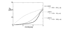
実施例、比較例1,2にかかるノイズ抑制シートについて、周波数毎の伝送減衰率Rtpの変化を示すグラフを図4に示した。
これらの結果から、実施例のノイズ抑制シートは、比較例2の磁性体を用いたノイズ抑制シートと同様のノイズ抑制特性、すなわち、高周波数域からのノイズ抑制特性を発揮していることが確認できた。
比較例1のノイズ抑制シートは、低周波数域から優れたノイズ抑制特性を発現しているが、高周波数用途で使用した場合にはメイン信号も抑制してしまうおそれがあるため、磁性体を用いたノイズ抑制シートの相当品としては不適当なものであった。
[Evaluation]
About the noise suppression sheet | seat concerning an Example and Comparative Examples 1 and 2, the graph which shows the change of the transmission attenuation factor Rtp for every frequency was shown in FIG.
From these results, it is confirmed that the noise suppression sheet of the example exhibits the same noise suppression characteristics as the noise suppression sheet using the magnetic material of Comparative Example 2, that is, the noise suppression characteristics from the high frequency range. did it.
The noise suppression sheet of Comparative Example 1 expresses excellent noise suppression characteristics from the low frequency range, but when used in high frequency applications, the main signal may be suppressed. The noise suppression sheet was not suitable as an equivalent product.
本発明にかかるノイズ抑制体、ノイズ抑制シート、塗装物品およびこれらの製造方法は、携帯電話や回路基板を被覆して、特に高周波ノイズの発生や漏洩、相互干渉による誤作動を防止するためのノイズ抑制体、ノイズ抑制シート、塗装物品およびこれらの製造方法として好適に利用できる。 The noise suppressor, noise suppression sheet, coated article, and manufacturing method thereof according to the present invention cover a mobile phone or a circuit board, and in particular, noise for preventing generation or leakage of high frequency noise and malfunction due to mutual interference. It can utilize suitably as a suppression body, a noise suppression sheet | seat, a coated article, and these manufacturing methods.
10 ノイズ抑制体
11 導電性粒子
12 絶縁層
13 原料混合物
14 コーティング組成物
15 乾燥塗膜
20 混合手段
30 塗工手段
40 離型性シートまたは被塗装物
50 加圧手段
DESCRIPTION OF
Claims (11)
Priority Applications (1)
| Application Number | Priority Date | Filing Date | Title |
|---|---|---|---|
| JP2008256700A JP5424606B2 (en) | 2008-10-01 | 2008-10-01 | Noise suppressor and manufacturing method thereof |
Applications Claiming Priority (1)
| Application Number | Priority Date | Filing Date | Title |
|---|---|---|---|
| JP2008256700A JP5424606B2 (en) | 2008-10-01 | 2008-10-01 | Noise suppressor and manufacturing method thereof |
Publications (2)
| Publication Number | Publication Date |
|---|---|
| JP2010087372A true JP2010087372A (en) | 2010-04-15 |
| JP5424606B2 JP5424606B2 (en) | 2014-02-26 |
Family
ID=42251013
Family Applications (1)
| Application Number | Title | Priority Date | Filing Date |
|---|---|---|---|
| JP2008256700A Expired - Fee Related JP5424606B2 (en) | 2008-10-01 | 2008-10-01 | Noise suppressor and manufacturing method thereof |
Country Status (1)
| Country | Link |
|---|---|
| JP (1) | JP5424606B2 (en) |
Cited By (7)
| Publication number | Priority date | Publication date | Assignee | Title |
|---|---|---|---|---|
| JP2011014650A (en) * | 2009-06-30 | 2011-01-20 | Panasonic Electric Works Co Ltd | Electromagnetic shielding molding material, electromagnetic shielding molding for electronic component, electromagnetic shielding molding for building material, and method of manufacturing the electromagnetic shielding molding material |
| WO2011149039A1 (en) * | 2010-05-27 | 2011-12-01 | 日東電工株式会社 | Dielectric material sheet and process for production thereof, and electromagnetic wave absorber |
| JP2012204734A (en) * | 2011-03-28 | 2012-10-22 | Shachihata Inc | Radio wave suppression sheet, and electronic apparatus and radio wave suppression component equipped with this sheet |
| WO2014087883A1 (en) * | 2012-12-03 | 2014-06-12 | 積水化学工業株式会社 | Electromagnetic wave blocking material and layered body for elecromagnetic wave blocking |
| KR20180098547A (en) | 2015-12-25 | 2018-09-04 | 니폰 제온 가부시키가이샤 | Electromagnetic wave absorbing material and electromagnetic wave absorber |
| US20180375215A1 (en) * | 2015-12-25 | 2018-12-27 | Zeon Corporation | Electromagnetic wave absorption material, electromagnetic wave absorber, and production methods therefor |
| JP7567615B2 (en) | 2021-03-26 | 2024-10-16 | 住友金属鉱山株式会社 | Electromagnetic wave absorbing material, electromagnetic wave absorber, and electronic element, electronic component, or electronic device provided with said electromagnetic wave absorber |
Citations (9)
| Publication number | Priority date | Publication date | Assignee | Title |
|---|---|---|---|---|
| JPH0544149A (en) * | 1991-08-08 | 1993-02-23 | Showa Denko Kk | Non-oriented nonwoven fabric and its production |
| JP2000244167A (en) * | 1999-02-19 | 2000-09-08 | Hitachi Maxell Ltd | Electromagnetic-wave-disturbance preventive material |
| JP2000357893A (en) * | 1999-04-13 | 2000-12-26 | Nippon Paint Co Ltd | Electromagnetic wave shielding film and electromagnetic wave shielding paint |
| JP2002198683A (en) * | 2000-12-25 | 2002-07-12 | Nippon Paint Co Ltd | Electromagnetic wave absorber |
| JP2003258490A (en) * | 2002-03-06 | 2003-09-12 | Tomoegawa Paper Co Ltd | Electromagnetic wave shielding material, and manufacturing method thereof |
| JP2004221522A (en) * | 2002-11-18 | 2004-08-05 | Alps Electric Co Ltd | Radio wave absorber and manufacturing method therefor |
| JP2005183732A (en) * | 2003-12-19 | 2005-07-07 | Inoac Corp | Electromagnetic wave absorber and manufacturing method thereof |
| JP2008118116A (en) * | 2006-10-13 | 2008-05-22 | Toray Ind Inc | Noise suppressing sheet |
| JP2009123799A (en) * | 2007-11-13 | 2009-06-04 | Mitsubishi Gas Chem Co Inc | Noise suppressor and noise suppression film |
-
2008
- 2008-10-01 JP JP2008256700A patent/JP5424606B2/en not_active Expired - Fee Related
Patent Citations (9)
| Publication number | Priority date | Publication date | Assignee | Title |
|---|---|---|---|---|
| JPH0544149A (en) * | 1991-08-08 | 1993-02-23 | Showa Denko Kk | Non-oriented nonwoven fabric and its production |
| JP2000244167A (en) * | 1999-02-19 | 2000-09-08 | Hitachi Maxell Ltd | Electromagnetic-wave-disturbance preventive material |
| JP2000357893A (en) * | 1999-04-13 | 2000-12-26 | Nippon Paint Co Ltd | Electromagnetic wave shielding film and electromagnetic wave shielding paint |
| JP2002198683A (en) * | 2000-12-25 | 2002-07-12 | Nippon Paint Co Ltd | Electromagnetic wave absorber |
| JP2003258490A (en) * | 2002-03-06 | 2003-09-12 | Tomoegawa Paper Co Ltd | Electromagnetic wave shielding material, and manufacturing method thereof |
| JP2004221522A (en) * | 2002-11-18 | 2004-08-05 | Alps Electric Co Ltd | Radio wave absorber and manufacturing method therefor |
| JP2005183732A (en) * | 2003-12-19 | 2005-07-07 | Inoac Corp | Electromagnetic wave absorber and manufacturing method thereof |
| JP2008118116A (en) * | 2006-10-13 | 2008-05-22 | Toray Ind Inc | Noise suppressing sheet |
| JP2009123799A (en) * | 2007-11-13 | 2009-06-04 | Mitsubishi Gas Chem Co Inc | Noise suppressor and noise suppression film |
Cited By (11)
| Publication number | Priority date | Publication date | Assignee | Title |
|---|---|---|---|---|
| JP2011014650A (en) * | 2009-06-30 | 2011-01-20 | Panasonic Electric Works Co Ltd | Electromagnetic shielding molding material, electromagnetic shielding molding for electronic component, electromagnetic shielding molding for building material, and method of manufacturing the electromagnetic shielding molding material |
| WO2011149039A1 (en) * | 2010-05-27 | 2011-12-01 | 日東電工株式会社 | Dielectric material sheet and process for production thereof, and electromagnetic wave absorber |
| JP2011249614A (en) * | 2010-05-27 | 2011-12-08 | Nitto Denko Corp | Dielectric sheet and method for producing the same, and electromagnetic wave absorber |
| CN102907193A (en) * | 2010-05-27 | 2013-01-30 | 日东电工株式会社 | Dielectric material sheet and process for production thereof, and electromagnetic wave absorber |
| JP2012204734A (en) * | 2011-03-28 | 2012-10-22 | Shachihata Inc | Radio wave suppression sheet, and electronic apparatus and radio wave suppression component equipped with this sheet |
| WO2014087883A1 (en) * | 2012-12-03 | 2014-06-12 | 積水化学工業株式会社 | Electromagnetic wave blocking material and layered body for elecromagnetic wave blocking |
| US10597508B2 (en) | 2012-12-03 | 2020-03-24 | Sekisui Chemical Co., Ltd. | Electromagnetic wave shielding material and layered body for electromagnetic wave shielding |
| KR20180098547A (en) | 2015-12-25 | 2018-09-04 | 니폰 제온 가부시키가이샤 | Electromagnetic wave absorbing material and electromagnetic wave absorber |
| US20180375215A1 (en) * | 2015-12-25 | 2018-12-27 | Zeon Corporation | Electromagnetic wave absorption material, electromagnetic wave absorber, and production methods therefor |
| US11235560B2 (en) | 2015-12-25 | 2022-02-01 | Zeon Corporation | Electromagnetic wave absorption material and electromagnetic wave absorber |
| JP7567615B2 (en) | 2021-03-26 | 2024-10-16 | 住友金属鉱山株式会社 | Electromagnetic wave absorbing material, electromagnetic wave absorber, and electronic element, electronic component, or electronic device provided with said electromagnetic wave absorber |
Also Published As
| Publication number | Publication date |
|---|---|
| JP5424606B2 (en) | 2014-02-26 |
Similar Documents
| Publication | Publication Date | Title |
|---|---|---|
| JP5424606B2 (en) | Noise suppressor and manufacturing method thereof | |
| JP4216917B2 (en) | Chip bead element and manufacturing method thereof | |
| US20080292891A1 (en) | Electromagnetic wave shielding sheet | |
| JPH05140368A (en) | Shielding material and shielded electric wire and cable product | |
| KR20150096655A (en) | Electromagnetic interference suppression body | |
| JP5940279B2 (en) | Manufacturing method of electromagnetic shielding material for FPC | |
| CN103144377A (en) | Composite electromagnetic-shielding copper clad laminate with heat conduction effect and manufacture method thereof | |
| JP5218396B2 (en) | Electromagnetic interference suppression sheet, high-frequency signal flat cable, flexible printed circuit board, and electromagnetic interference suppression sheet manufacturing method | |
| JP2004200534A (en) | Electromagnetic wave absorbing thermal conductive sheet | |
| JP5993485B2 (en) | FPC with electromagnetic shielding material for FPC | |
| JP6939551B2 (en) | Ferrite laminate and noise suppression sheet | |
| JP2008244358A (en) | Noise suppressing sheet and coating material | |
| JP4859028B2 (en) | Electromagnetic wave prevention sheet, electromagnetic wave prevention sheet manufacturing method, and electromagnetic wave prevention structure of electronic component | |
| TWM553100U (en) | Electromagnetic shielding film | |
| JP2000244167A (en) | Electromagnetic-wave-disturbance preventive material | |
| JP2009125974A (en) | Flame retardant laminated sheet | |
| US11756714B2 (en) | Composite magnetic material and method for manufacturing same | |
| JP6202767B2 (en) | Manufacturing method of FPC provided with electromagnetic shielding material for FPC | |
| JP5361055B2 (en) | Composite sheet | |
| JP5912278B2 (en) | Electromagnetic interference suppressor | |
| JP2008270714A (en) | Electromagnetic wave shielding sheet | |
| JP2013182931A (en) | Electromagnetic noise suppression member | |
| JP2004140026A (en) | Compound magnetic sheet | |
| JP6268221B2 (en) | Manufacturing method of electromagnetic shielding material for FPC | |
| TWI540191B (en) | Electromagnetic wave shielding coating |
Legal Events
| Date | Code | Title | Description |
|---|---|---|---|
| A621 | Written request for application examination |
Free format text: JAPANESE INTERMEDIATE CODE: A621 Effective date: 20110811 |
|
| A977 | Report on retrieval |
Free format text: JAPANESE INTERMEDIATE CODE: A971007 Effective date: 20120820 |
|
| A131 | Notification of reasons for refusal |
Free format text: JAPANESE INTERMEDIATE CODE: A131 Effective date: 20120911 |
|
| A521 | Request for written amendment filed |
Free format text: JAPANESE INTERMEDIATE CODE: A523 Effective date: 20121023 |
|
| A131 | Notification of reasons for refusal |
Free format text: JAPANESE INTERMEDIATE CODE: A131 Effective date: 20130625 |
|
| A521 | Request for written amendment filed |
Free format text: JAPANESE INTERMEDIATE CODE: A523 Effective date: 20130722 |
|
| TRDD | Decision of grant or rejection written | ||
| A01 | Written decision to grant a patent or to grant a registration (utility model) |
Free format text: JAPANESE INTERMEDIATE CODE: A01 Effective date: 20131126 |
|
| A61 | First payment of annual fees (during grant procedure) |
Free format text: JAPANESE INTERMEDIATE CODE: A61 Effective date: 20131126 |
|
| R150 | Certificate of patent or registration of utility model |
Free format text: JAPANESE INTERMEDIATE CODE: R150 Ref document number: 5424606 Country of ref document: JP Free format text: JAPANESE INTERMEDIATE CODE: R150 |
|
| R250 | Receipt of annual fees |
Free format text: JAPANESE INTERMEDIATE CODE: R250 |
|
| R250 | Receipt of annual fees |
Free format text: JAPANESE INTERMEDIATE CODE: R250 |
|
| R250 | Receipt of annual fees |
Free format text: JAPANESE INTERMEDIATE CODE: R250 |
|
| S533 | Written request for registration of change of name |
Free format text: JAPANESE INTERMEDIATE CODE: R313533 |
|
| R350 | Written notification of registration of transfer |
Free format text: JAPANESE INTERMEDIATE CODE: R350 |
|
| R250 | Receipt of annual fees |
Free format text: JAPANESE INTERMEDIATE CODE: R250 |
|
| R250 | Receipt of annual fees |
Free format text: JAPANESE INTERMEDIATE CODE: R250 |
|
| R250 | Receipt of annual fees |
Free format text: JAPANESE INTERMEDIATE CODE: R250 |
|
| R250 | Receipt of annual fees |
Free format text: JAPANESE INTERMEDIATE CODE: R250 |
|
| LAPS | Cancellation because of no payment of annual fees |