JP6560744B2 - Blood processing apparatus comprising a holder device for a measuring instrument - Google Patents
Blood processing apparatus comprising a holder device for a measuring instrument Download PDFInfo
- Publication number
- JP6560744B2 JP6560744B2 JP2017511607A JP2017511607A JP6560744B2 JP 6560744 B2 JP6560744 B2 JP 6560744B2 JP 2017511607 A JP2017511607 A JP 2017511607A JP 2017511607 A JP2017511607 A JP 2017511607A JP 6560744 B2 JP6560744 B2 JP 6560744B2
- Authority
- JP
- Japan
- Prior art keywords
- chamber
- blood
- chamber member
- sensor element
- measuring instrument
- Prior art date
- Legal status (The legal status is an assumption and is not a legal conclusion. Google has not performed a legal analysis and makes no representation as to the accuracy of the status listed.)
- Active
Links
- 210000004369 blood Anatomy 0.000 title claims description 100
- 239000008280 blood Substances 0.000 title claims description 100
- 230000002093 peripheral effect Effects 0.000 claims description 32
- 238000003780 insertion Methods 0.000 claims description 28
- 230000037431 insertion Effects 0.000 claims description 28
- 238000005534 hematocrit Methods 0.000 claims description 25
- 239000012530 fluid Substances 0.000 claims description 10
- 230000005484 gravity Effects 0.000 claims description 8
- 238000005259 measurement Methods 0.000 claims description 6
- 238000004140 cleaning Methods 0.000 description 39
- 230000007246 mechanism Effects 0.000 description 23
- 239000007788 liquid Substances 0.000 description 13
- 238000005406 washing Methods 0.000 description 11
- 230000009286 beneficial effect Effects 0.000 description 8
- 230000017531 blood circulation Effects 0.000 description 6
- 238000000926 separation method Methods 0.000 description 6
- 239000002699 waste material Substances 0.000 description 6
- 230000009471 action Effects 0.000 description 4
- 230000008878 coupling Effects 0.000 description 4
- 238000010168 coupling process Methods 0.000 description 4
- 238000005859 coupling reaction Methods 0.000 description 4
- 238000006073 displacement reaction Methods 0.000 description 4
- 239000000463 material Substances 0.000 description 4
- 230000002572 peristaltic effect Effects 0.000 description 4
- 238000005086 pumping Methods 0.000 description 4
- 238000011144 upstream manufacturing Methods 0.000 description 4
- FAPWRFPIFSIZLT-UHFFFAOYSA-M Sodium chloride Chemical compound [Na+].[Cl-] FAPWRFPIFSIZLT-UHFFFAOYSA-M 0.000 description 3
- 238000000034 method Methods 0.000 description 3
- 230000008569 process Effects 0.000 description 3
- 230000005855 radiation Effects 0.000 description 3
- 239000011780 sodium chloride Substances 0.000 description 3
- 230000000694 effects Effects 0.000 description 2
- 210000003743 erythrocyte Anatomy 0.000 description 2
- 102000001554 Hemoglobins Human genes 0.000 description 1
- 108010054147 Hemoglobins Proteins 0.000 description 1
- 239000003146 anticoagulant agent Substances 0.000 description 1
- 229940127219 anticoagulant drug Drugs 0.000 description 1
- QVGXLLKOCUKJST-UHFFFAOYSA-N atomic oxygen Chemical compound [O] QVGXLLKOCUKJST-UHFFFAOYSA-N 0.000 description 1
- 238000009529 body temperature measurement Methods 0.000 description 1
- 210000004027 cell Anatomy 0.000 description 1
- 238000000502 dialysis Methods 0.000 description 1
- 238000001746 injection moulding Methods 0.000 description 1
- 210000000265 leukocyte Anatomy 0.000 description 1
- 229910052760 oxygen Inorganic materials 0.000 description 1
- 239000001301 oxygen Substances 0.000 description 1
- 239000002504 physiological saline solution Substances 0.000 description 1
- 239000004033 plastic Substances 0.000 description 1
- 239000004417 polycarbonate Substances 0.000 description 1
- 229920000515 polycarbonate Polymers 0.000 description 1
- 229920000642 polymer Polymers 0.000 description 1
- 238000001556 precipitation Methods 0.000 description 1
- 230000000644 propagated effect Effects 0.000 description 1
- 238000011084 recovery Methods 0.000 description 1
- 238000004064 recycling Methods 0.000 description 1
- 230000004044 response Effects 0.000 description 1
- 230000000630 rising effect Effects 0.000 description 1
- 238000001356 surgical procedure Methods 0.000 description 1
Images


Classifications
-
- A—HUMAN NECESSITIES
- A61—MEDICAL OR VETERINARY SCIENCE; HYGIENE
- A61B—DIAGNOSIS; SURGERY; IDENTIFICATION
- A61B5/00—Measuring for diagnostic purposes; Identification of persons
- A61B5/145—Measuring characteristics of blood in vivo, e.g. gas concentration, pH value; Measuring characteristics of body fluids or tissues, e.g. interstitial fluid, cerebral tissue
- A61B5/14535—Measuring characteristics of blood in vivo, e.g. gas concentration, pH value; Measuring characteristics of body fluids or tissues, e.g. interstitial fluid, cerebral tissue for measuring haematocrit
-
- A—HUMAN NECESSITIES
- A61—MEDICAL OR VETERINARY SCIENCE; HYGIENE
- A61M—DEVICES FOR INTRODUCING MEDIA INTO, OR ONTO, THE BODY; DEVICES FOR TRANSDUCING BODY MEDIA OR FOR TAKING MEDIA FROM THE BODY; DEVICES FOR PRODUCING OR ENDING SLEEP OR STUPOR
- A61M1/00—Suction or pumping devices for medical purposes; Devices for carrying-off, for treatment of, or for carrying-over, body-liquids; Drainage systems
- A61M1/02—Blood transfusion apparatus
- A61M1/0259—Apparatus for treatment of blood or blood constituents not otherwise provided for
-
- A—HUMAN NECESSITIES
- A61—MEDICAL OR VETERINARY SCIENCE; HYGIENE
- A61M—DEVICES FOR INTRODUCING MEDIA INTO, OR ONTO, THE BODY; DEVICES FOR TRANSDUCING BODY MEDIA OR FOR TAKING MEDIA FROM THE BODY; DEVICES FOR PRODUCING OR ENDING SLEEP OR STUPOR
- A61M1/00—Suction or pumping devices for medical purposes; Devices for carrying-off, for treatment of, or for carrying-over, body-liquids; Drainage systems
- A61M1/02—Blood transfusion apparatus
- A61M1/0281—Apparatus for treatment of blood or blood constituents prior to transfusion, e.g. washing, filtering or thawing
-
- A—HUMAN NECESSITIES
- A61—MEDICAL OR VETERINARY SCIENCE; HYGIENE
- A61M—DEVICES FOR INTRODUCING MEDIA INTO, OR ONTO, THE BODY; DEVICES FOR TRANSDUCING BODY MEDIA OR FOR TAKING MEDIA FROM THE BODY; DEVICES FOR PRODUCING OR ENDING SLEEP OR STUPOR
- A61M1/00—Suction or pumping devices for medical purposes; Devices for carrying-off, for treatment of, or for carrying-over, body-liquids; Drainage systems
- A61M1/36—Other treatment of blood in a by-pass of the natural circulatory system, e.g. temperature adaptation, irradiation ; Extra-corporeal blood circuits
- A61M1/3607—Regulation parameters
- A61M1/3609—Physical characteristics of the blood, e.g. haematocrit, urea
- A61M1/361—Physical characteristics of the blood, e.g. haematocrit, urea before treatment
-
- A—HUMAN NECESSITIES
- A61—MEDICAL OR VETERINARY SCIENCE; HYGIENE
- A61M—DEVICES FOR INTRODUCING MEDIA INTO, OR ONTO, THE BODY; DEVICES FOR TRANSDUCING BODY MEDIA OR FOR TAKING MEDIA FROM THE BODY; DEVICES FOR PRODUCING OR ENDING SLEEP OR STUPOR
- A61M1/00—Suction or pumping devices for medical purposes; Devices for carrying-off, for treatment of, or for carrying-over, body-liquids; Drainage systems
- A61M1/36—Other treatment of blood in a by-pass of the natural circulatory system, e.g. temperature adaptation, irradiation ; Extra-corporeal blood circuits
- A61M1/3607—Regulation parameters
- A61M1/3609—Physical characteristics of the blood, e.g. haematocrit, urea
- A61M1/3612—Physical characteristics of the blood, e.g. haematocrit, urea after treatment
-
- A—HUMAN NECESSITIES
- A61—MEDICAL OR VETERINARY SCIENCE; HYGIENE
- A61M—DEVICES FOR INTRODUCING MEDIA INTO, OR ONTO, THE BODY; DEVICES FOR TRANSDUCING BODY MEDIA OR FOR TAKING MEDIA FROM THE BODY; DEVICES FOR PRODUCING OR ENDING SLEEP OR STUPOR
- A61M1/00—Suction or pumping devices for medical purposes; Devices for carrying-off, for treatment of, or for carrying-over, body-liquids; Drainage systems
- A61M1/36—Other treatment of blood in a by-pass of the natural circulatory system, e.g. temperature adaptation, irradiation ; Extra-corporeal blood circuits
- A61M1/3621—Extra-corporeal blood circuits
- A61M1/3627—Degassing devices; Buffer reservoirs; Drip chambers; Blood filters
- A61M1/3632—Combined venous-cardiotomy reservoirs
-
- A—HUMAN NECESSITIES
- A61—MEDICAL OR VETERINARY SCIENCE; HYGIENE
- A61M—DEVICES FOR INTRODUCING MEDIA INTO, OR ONTO, THE BODY; DEVICES FOR TRANSDUCING BODY MEDIA OR FOR TAKING MEDIA FROM THE BODY; DEVICES FOR PRODUCING OR ENDING SLEEP OR STUPOR
- A61M1/00—Suction or pumping devices for medical purposes; Devices for carrying-off, for treatment of, or for carrying-over, body-liquids; Drainage systems
- A61M1/36—Other treatment of blood in a by-pass of the natural circulatory system, e.g. temperature adaptation, irradiation ; Extra-corporeal blood circuits
- A61M1/3692—Washing or rinsing blood or blood constituents
-
- A—HUMAN NECESSITIES
- A61—MEDICAL OR VETERINARY SCIENCE; HYGIENE
- A61M—DEVICES FOR INTRODUCING MEDIA INTO, OR ONTO, THE BODY; DEVICES FOR TRANSDUCING BODY MEDIA OR FOR TAKING MEDIA FROM THE BODY; DEVICES FOR PRODUCING OR ENDING SLEEP OR STUPOR
- A61M1/00—Suction or pumping devices for medical purposes; Devices for carrying-off, for treatment of, or for carrying-over, body-liquids; Drainage systems
- A61M1/36—Other treatment of blood in a by-pass of the natural circulatory system, e.g. temperature adaptation, irradiation ; Extra-corporeal blood circuits
- A61M1/3693—Other treatment of blood in a by-pass of the natural circulatory system, e.g. temperature adaptation, irradiation ; Extra-corporeal blood circuits using separation based on different densities of components, e.g. centrifuging
-
- B—PERFORMING OPERATIONS; TRANSPORTING
- B01—PHYSICAL OR CHEMICAL PROCESSES OR APPARATUS IN GENERAL
- B01L—CHEMICAL OR PHYSICAL LABORATORY APPARATUS FOR GENERAL USE
- B01L3/00—Containers or dishes for laboratory use, e.g. laboratory glassware; Droppers
- B01L3/50—Containers for the purpose of retaining a material to be analysed, e.g. test tubes
- B01L3/502—Containers for the purpose of retaining a material to be analysed, e.g. test tubes with fluid transport, e.g. in multi-compartment structures
-
- G—PHYSICS
- G01—MEASURING; TESTING
- G01N—INVESTIGATING OR ANALYSING MATERIALS BY DETERMINING THEIR CHEMICAL OR PHYSICAL PROPERTIES
- G01N15/00—Investigating characteristics of particles; Investigating permeability, pore-volume or surface-area of porous materials
- G01N15/04—Investigating sedimentation of particle suspensions
- G01N15/05—Investigating sedimentation of particle suspensions in blood
-
- G—PHYSICS
- G01—MEASURING; TESTING
- G01N—INVESTIGATING OR ANALYSING MATERIALS BY DETERMINING THEIR CHEMICAL OR PHYSICAL PROPERTIES
- G01N29/00—Investigating or analysing materials by the use of ultrasonic, sonic or infrasonic waves; Visualisation of the interior of objects by transmitting ultrasonic or sonic waves through the object
- G01N29/02—Analysing fluids
- G01N29/024—Analysing fluids by measuring propagation velocity or propagation time of acoustic waves
-
- G—PHYSICS
- G01—MEASURING; TESTING
- G01N—INVESTIGATING OR ANALYSING MATERIALS BY DETERMINING THEIR CHEMICAL OR PHYSICAL PROPERTIES
- G01N29/00—Investigating or analysing materials by the use of ultrasonic, sonic or infrasonic waves; Visualisation of the interior of objects by transmitting ultrasonic or sonic waves through the object
- G01N29/22—Details, e.g. general constructional or apparatus details
- G01N29/222—Constructional or flow details for analysing fluids
-
- G—PHYSICS
- G01—MEASURING; TESTING
- G01N—INVESTIGATING OR ANALYSING MATERIALS BY DETERMINING THEIR CHEMICAL OR PHYSICAL PROPERTIES
- G01N29/00—Investigating or analysing materials by the use of ultrasonic, sonic or infrasonic waves; Visualisation of the interior of objects by transmitting ultrasonic or sonic waves through the object
- G01N29/22—Details, e.g. general constructional or apparatus details
- G01N29/223—Supports, positioning or alignment in fixed situation
-
- A—HUMAN NECESSITIES
- A61—MEDICAL OR VETERINARY SCIENCE; HYGIENE
- A61B—DIAGNOSIS; SURGERY; IDENTIFICATION
- A61B2560/00—Constructional details of operational features of apparatus; Accessories for medical measuring apparatus
- A61B2560/04—Constructional details of apparatus
- A61B2560/0437—Trolley or cart-type apparatus
-
- A—HUMAN NECESSITIES
- A61—MEDICAL OR VETERINARY SCIENCE; HYGIENE
- A61B—DIAGNOSIS; SURGERY; IDENTIFICATION
- A61B5/00—Measuring for diagnostic purposes; Identification of persons
- A61B5/48—Other medical applications
- A61B5/4836—Diagnosis combined with treatment in closed-loop systems or methods
-
- A—HUMAN NECESSITIES
- A61—MEDICAL OR VETERINARY SCIENCE; HYGIENE
- A61M—DEVICES FOR INTRODUCING MEDIA INTO, OR ONTO, THE BODY; DEVICES FOR TRANSDUCING BODY MEDIA OR FOR TAKING MEDIA FROM THE BODY; DEVICES FOR PRODUCING OR ENDING SLEEP OR STUPOR
- A61M1/00—Suction or pumping devices for medical purposes; Devices for carrying-off, for treatment of, or for carrying-over, body-liquids; Drainage systems
- A61M1/02—Blood transfusion apparatus
- A61M1/0209—Multiple bag systems for separating or storing blood components
-
- A—HUMAN NECESSITIES
- A61—MEDICAL OR VETERINARY SCIENCE; HYGIENE
- A61M—DEVICES FOR INTRODUCING MEDIA INTO, OR ONTO, THE BODY; DEVICES FOR TRANSDUCING BODY MEDIA OR FOR TAKING MEDIA FROM THE BODY; DEVICES FOR PRODUCING OR ENDING SLEEP OR STUPOR
- A61M2205/00—General characteristics of the apparatus
- A61M2205/12—General characteristics of the apparatus with interchangeable cassettes forming partially or totally the fluid circuit
- A61M2205/121—General characteristics of the apparatus with interchangeable cassettes forming partially or totally the fluid circuit interface between cassette and base
-
- A—HUMAN NECESSITIES
- A61—MEDICAL OR VETERINARY SCIENCE; HYGIENE
- A61M—DEVICES FOR INTRODUCING MEDIA INTO, OR ONTO, THE BODY; DEVICES FOR TRANSDUCING BODY MEDIA OR FOR TAKING MEDIA FROM THE BODY; DEVICES FOR PRODUCING OR ENDING SLEEP OR STUPOR
- A61M2205/00—General characteristics of the apparatus
- A61M2205/33—Controlling, regulating or measuring
- A61M2205/3306—Optical measuring means
- A61M2205/3313—Optical measuring means used specific wavelengths
-
- A—HUMAN NECESSITIES
- A61—MEDICAL OR VETERINARY SCIENCE; HYGIENE
- A61M—DEVICES FOR INTRODUCING MEDIA INTO, OR ONTO, THE BODY; DEVICES FOR TRANSDUCING BODY MEDIA OR FOR TAKING MEDIA FROM THE BODY; DEVICES FOR PRODUCING OR ENDING SLEEP OR STUPOR
- A61M2205/00—General characteristics of the apparatus
- A61M2205/33—Controlling, regulating or measuring
- A61M2205/3368—Temperature
-
- A—HUMAN NECESSITIES
- A61—MEDICAL OR VETERINARY SCIENCE; HYGIENE
- A61M—DEVICES FOR INTRODUCING MEDIA INTO, OR ONTO, THE BODY; DEVICES FOR TRANSDUCING BODY MEDIA OR FOR TAKING MEDIA FROM THE BODY; DEVICES FOR PRODUCING OR ENDING SLEEP OR STUPOR
- A61M2205/00—General characteristics of the apparatus
- A61M2205/33—Controlling, regulating or measuring
- A61M2205/3375—Acoustical, e.g. ultrasonic, measuring means
-
- A—HUMAN NECESSITIES
- A61—MEDICAL OR VETERINARY SCIENCE; HYGIENE
- A61M—DEVICES FOR INTRODUCING MEDIA INTO, OR ONTO, THE BODY; DEVICES FOR TRANSDUCING BODY MEDIA OR FOR TAKING MEDIA FROM THE BODY; DEVICES FOR PRODUCING OR ENDING SLEEP OR STUPOR
- A61M2209/00—Ancillary equipment
- A61M2209/08—Supports for equipment
- A61M2209/084—Supporting bases, stands for equipment
- A61M2209/086—Docking stations
-
- A—HUMAN NECESSITIES
- A61—MEDICAL OR VETERINARY SCIENCE; HYGIENE
- A61M—DEVICES FOR INTRODUCING MEDIA INTO, OR ONTO, THE BODY; DEVICES FOR TRANSDUCING BODY MEDIA OR FOR TAKING MEDIA FROM THE BODY; DEVICES FOR PRODUCING OR ENDING SLEEP OR STUPOR
- A61M2230/00—Measuring parameters of the user
- A61M2230/20—Blood composition characteristics
- A61M2230/207—Blood composition characteristics hematocrit
-
- B—PERFORMING OPERATIONS; TRANSPORTING
- B01—PHYSICAL OR CHEMICAL PROCESSES OR APPARATUS IN GENERAL
- B01L—CHEMICAL OR PHYSICAL LABORATORY APPARATUS FOR GENERAL USE
- B01L2200/00—Solutions for specific problems relating to chemical or physical laboratory apparatus
- B01L2200/02—Adapting objects or devices to another
- B01L2200/025—Align devices or objects to ensure defined positions relative to each other
-
- B—PERFORMING OPERATIONS; TRANSPORTING
- B01—PHYSICAL OR CHEMICAL PROCESSES OR APPARATUS IN GENERAL
- B01L—CHEMICAL OR PHYSICAL LABORATORY APPARATUS FOR GENERAL USE
- B01L2300/00—Additional constructional details
- B01L2300/06—Auxiliary integrated devices, integrated components
- B01L2300/0609—Holders integrated in container to position an object
-
- B—PERFORMING OPERATIONS; TRANSPORTING
- B01—PHYSICAL OR CHEMICAL PROCESSES OR APPARATUS IN GENERAL
- B01L—CHEMICAL OR PHYSICAL LABORATORY APPARATUS FOR GENERAL USE
- B01L2300/00—Additional constructional details
- B01L2300/06—Auxiliary integrated devices, integrated components
- B01L2300/0627—Sensor or part of a sensor is integrated
-
- B—PERFORMING OPERATIONS; TRANSPORTING
- B01—PHYSICAL OR CHEMICAL PROCESSES OR APPARATUS IN GENERAL
- B01L—CHEMICAL OR PHYSICAL LABORATORY APPARATUS FOR GENERAL USE
- B01L2300/00—Additional constructional details
- B01L2300/08—Geometry, shape and general structure
- B01L2300/0848—Specific forms of parts of containers
- B01L2300/0851—Bottom walls
-
- G—PHYSICS
- G01—MEASURING; TESTING
- G01N—INVESTIGATING OR ANALYSING MATERIALS BY DETERMINING THEIR CHEMICAL OR PHYSICAL PROPERTIES
- G01N15/00—Investigating characteristics of particles; Investigating permeability, pore-volume or surface-area of porous materials
- G01N15/01—Investigating characteristics of particles; Investigating permeability, pore-volume or surface-area of porous materials specially adapted for biological cells, e.g. blood cells
-
- G—PHYSICS
- G01—MEASURING; TESTING
- G01N—INVESTIGATING OR ANALYSING MATERIALS BY DETERMINING THEIR CHEMICAL OR PHYSICAL PROPERTIES
- G01N15/00—Investigating characteristics of particles; Investigating permeability, pore-volume or surface-area of porous materials
- G01N2015/0092—Monitoring flocculation or agglomeration
-
- G—PHYSICS
- G01—MEASURING; TESTING
- G01N—INVESTIGATING OR ANALYSING MATERIALS BY DETERMINING THEIR CHEMICAL OR PHYSICAL PROPERTIES
- G01N15/00—Investigating characteristics of particles; Investigating permeability, pore-volume or surface-area of porous materials
- G01N15/01—Investigating characteristics of particles; Investigating permeability, pore-volume or surface-area of porous materials specially adapted for biological cells, e.g. blood cells
- G01N2015/012—Red blood cells
-
- G—PHYSICS
- G01—MEASURING; TESTING
- G01N—INVESTIGATING OR ANALYSING MATERIALS BY DETERMINING THEIR CHEMICAL OR PHYSICAL PROPERTIES
- G01N15/00—Investigating characteristics of particles; Investigating permeability, pore-volume or surface-area of porous materials
- G01N15/04—Investigating sedimentation of particle suspensions
- G01N15/05—Investigating sedimentation of particle suspensions in blood
- G01N2015/055—Investigating sedimentation of particle suspensions in blood for hematocrite determination
-
- G—PHYSICS
- G01—MEASURING; TESTING
- G01N—INVESTIGATING OR ANALYSING MATERIALS BY DETERMINING THEIR CHEMICAL OR PHYSICAL PROPERTIES
- G01N2291/00—Indexing codes associated with group G01N29/00
- G01N2291/02—Indexing codes associated with the analysed material
- G01N2291/024—Mixtures
- G01N2291/02466—Biological material, e.g. blood
-
- G—PHYSICS
- G01—MEASURING; TESTING
- G01N—INVESTIGATING OR ANALYSING MATERIALS BY DETERMINING THEIR CHEMICAL OR PHYSICAL PROPERTIES
- G01N2291/00—Indexing codes associated with group G01N29/00
- G01N2291/04—Wave modes and trajectories
- G01N2291/044—Internal reflections (echoes), e.g. on walls or defects
Landscapes
- Health & Medical Sciences (AREA)
- Heart & Thoracic Surgery (AREA)
- Life Sciences & Earth Sciences (AREA)
- Vascular Medicine (AREA)
- General Health & Medical Sciences (AREA)
- Public Health (AREA)
- Animal Behavior & Ethology (AREA)
- Biomedical Technology (AREA)
- Engineering & Computer Science (AREA)
- Veterinary Medicine (AREA)
- Hematology (AREA)
- Anesthesiology (AREA)
- Physics & Mathematics (AREA)
- Cardiology (AREA)
- Pathology (AREA)
- Chemical & Material Sciences (AREA)
- Analytical Chemistry (AREA)
- Immunology (AREA)
- General Physics & Mathematics (AREA)
- Biochemistry (AREA)
- Acoustics & Sound (AREA)
- Medical Informatics (AREA)
- Biophysics (AREA)
- Molecular Biology (AREA)
- Surgery (AREA)
- Optics & Photonics (AREA)
- Dispersion Chemistry (AREA)
- Clinical Laboratory Science (AREA)
- Chemical Kinetics & Catalysis (AREA)
- External Artificial Organs (AREA)
- Investigating Or Analysing Biological Materials (AREA)
Description
本発明は、請求項1のプリアンブルに記載の血液処理装置に関する。 The present invention relates to a blood processing apparatus according to the preamble of claim 1.
この種の血液処理装置は、血液流体を受け取る少なくとも1つのチャンバー部材を備える測定器を備える。少なくとも1つのチャンバー部材は、長手方向軸に沿って延在し、長手方向軸の周りに延在する周壁と、底壁及び頂壁とを備え、これらの壁はともに流れチャンバーを画定する。少なくとも1つのチャンバー部材は、流れチャンバー内への血液流体の流れを可能にする入口ポートと、流れチャンバーから出る血液流体の流れを可能にする出口ポートとを更に備える。血液処理装置は、測定器を保持するホルダー器具を更に備える。ホルダー器具は、測定器を収納する収納開口を有する基部と、測定器を収納開口内の挿入位置に係止する、基部に可動に配置された閉鎖部材とを備える。ホルダー器具によって、例えば使い捨てチューブセットの一部とすることができる測定器は、血液処理装置の動作のための血液処理装置のハウジングに取り付けることができる。 This type of blood processing apparatus comprises a measuring device comprising at least one chamber member for receiving blood fluid. The at least one chamber member extends along the longitudinal axis and includes a peripheral wall extending about the longitudinal axis, a bottom wall and a top wall, and these walls together define a flow chamber. The at least one chamber member further comprises an inlet port that allows blood fluid flow into the flow chamber and an outlet port that allows blood fluid flow out of the flow chamber. The blood processing apparatus further includes a holder device that holds the measuring device. The holder device includes a base having a storage opening for storing the measuring instrument, and a closing member movably disposed on the base for locking the measuring instrument at an insertion position in the storage opening. By means of a holder device, a measuring instrument, which can be part of a disposable tube set, for example, can be attached to the blood processing device housing for operation of the blood processing device.
ホルダー器具は、ホルダー器具の基部に配置される超音波センサー素子を備える。超音波センサー素子は、流れチャンバー内の血液流体のヘマトクリット値を測定するための超音波センサー信号を生成するようになっている。 The holder device comprises an ultrasonic sensor element arranged at the base of the holder device. The ultrasonic sensor element is adapted to generate an ultrasonic sensor signal for measuring a hematocrit value of blood fluid in the flow chamber.
特許文献1は、使い捨てカセットを挿入することができるホルダーチャンバーを備える透析機の形状の血液処理装置を開示している。使い捨てカセットは、チャンバー部材を通る血液の流れを可能にする入口ポート及び出口ポートを備えるチャンバー部材を備える。ホルダーチャンバーには温度センサー及び超音波センサーが配置され、チャンバー部材内の血液の温度及びチャンバー部材内の血液のヘマトクリット値を測定する。 Patent Document 1 discloses a blood treatment device in the form of a dialysis machine including a holder chamber into which a disposable cassette can be inserted. The disposable cassette comprises a chamber member with an inlet port and an outlet port that allows blood flow through the chamber member. A temperature sensor and an ultrasonic sensor are disposed in the holder chamber, and the temperature of blood in the chamber member and the hematocrit value of blood in the chamber member are measured.
特許文献2は、チューブを挿入することができるホルダー器具を備える体外血液処理用の医療機器を開示している。ホルダー器具は、異なる機能原理で動作する複数のセンサーユニット、特に熱センサー素子及び超音波センサー素子を備える。
特許文献3は、チューブを挿入することができるホルダー器具を開示している。ホルダー器具は、体外回路内を循環する血液のパラメーター、特に酸素飽和度、ヘモグロビン濃度及びヘマトクリットを求めるようになっている。
本発明の目的は、測定器をホルダー器具に容易に挿入することが可能であるとともに、特に測定器を通る血液の流れのヘマトクリット値を確実に測定することが可能である、測定器用のホルダー器具を備える血液処理装置を提供することである。 An object of the present invention is to provide a holder instrument for a measuring instrument that can easily insert the measuring instrument into a holder instrument and in particular can reliably measure the hematocrit value of the blood flow through the measuring instrument. It is providing the blood processing apparatus provided with this.
この目的は、請求項1に記載の特徴を備える血液処理装置によって達成される。 This object is achieved by a blood treatment device comprising the features of claim 1.
それによれば、超音波センサー素子が、測定器の挿入位置において、少なくとも1つのチャンバー部材の底壁に面し、底壁を通して流れチャンバー内に超音波信号を送信する。 Thereby, the ultrasonic sensor element faces the bottom wall of at least one chamber member at the insertion position of the measuring instrument and transmits an ultrasonic signal through the bottom wall and into the flow chamber.
これは、超音波センサー素子を測定器の底壁に結合するという構想に基づいている。測定器は、長手方向軸に沿って延在し、長手方向軸の周りに延在する周壁を備える。測定器のチャンバー部材は、特に、概して円筒形状を有することができ、底部には底壁があり、頂部には頂壁がある。測定器がホルダー器具に挿入されると、超音波センサー素子がチャンバー部材の底壁に位置することになるため、超音波センサー素子は、その超音波センサー信号を底壁へと結合し、底壁を介して、その信号をチャンバー部材の流れチャンバー内に送信する。すると、超音波センサー信号、例えば超音波パルスは、流れチャンバーを通って伝播し、チャンバー部材の異なる面において部分的に反射される。このような反射は、超音波センサー素子によってエコー信号として記録することができ、チャンバー部材内に収容される血液のヘマトクリットを求めるのに用いることができる。 This is based on the concept of coupling the ultrasonic sensor element to the bottom wall of the measuring instrument. The meter includes a peripheral wall extending along the longitudinal axis and extending about the longitudinal axis. The chamber member of the meter can in particular have a generally cylindrical shape, with a bottom wall at the bottom and a top wall at the top. When the measuring instrument is inserted into the holder instrument, the ultrasonic sensor element is located on the bottom wall of the chamber member, so the ultrasonic sensor element couples the ultrasonic sensor signal to the bottom wall, The signal is transmitted into the flow chamber of the chamber member via. An ultrasonic sensor signal, eg, an ultrasonic pulse, then propagates through the flow chamber and is partially reflected at different surfaces of the chamber member. Such reflection can be recorded as an echo signal by the ultrasonic sensor element and can be used to determine the hematocrit of blood contained in the chamber member.
1つの実施形態において、ホルダー器具の閉鎖部材は、測定器の挿入位置において、少なくとも1つのチャンバー部材に対して長手方向軸に沿って所定の力を及ぼすように設計されている。この所定の力は、例えば15Nよりも大きくすることができ、チャンバー部材の底壁を超音波センサー素子に対して押し付ける役目を果たし、それにより、チャンバー部材の底壁への超音波センサー素子の有益な結合が達成される。 In one embodiment, the closure member of the holder device is designed to exert a predetermined force along the longitudinal axis against the at least one chamber member at the insertion position of the meter. This predetermined force can be greater than, for example, 15 N and serves to press the bottom wall of the chamber member against the ultrasonic sensor element, thereby benefiting the ultrasonic sensor element to the bottom wall of the chamber member. Coupling is achieved.
このために、閉鎖部材は、収納開口の内側に向かって突出する固定要素を備えることができ、この固定要素は、測定器の挿入位置かつ閉鎖部材の閉鎖位置では、チャンバー部材が超音波センサー素子に対して押し付けられるようにチャンバー部材の頂壁に作用する。 For this purpose, the closure member can be provided with a fixing element projecting towards the inside of the storage opening, which means that the chamber member is an ultrasonic sensor element in the insertion position of the measuring instrument and in the closed position of the closing member. Acting on the top wall of the chamber member.
1つの実施形態において、超音波センサー素子は結合パッドを備え、結合パッドは、測定器の挿入位置では、少なくとも1つのチャンバー部材の底壁に当接する。結合パッドは、測定器の挿入位置において、底壁と、超音波センサー信号、特に超音波信号パルスを放出及び受信するように機能する、超音波センサー素子の構成要素との合間に位置する。結合パッドは、超音波センサー素子から底壁へ、また反対に底壁から超音波センサー素子へと超音波信号の有益な結合をもたらす材料からなる。 In one embodiment, the ultrasonic sensor element comprises a bond pad that abuts the bottom wall of at least one chamber member in the insertion position of the meter. The bond pad is located between the bottom wall and the components of the ultrasonic sensor element that function to emit and receive ultrasonic sensor signals, in particular ultrasonic signal pulses, at the insertion position of the measuring instrument. The bond pad is made of a material that provides a beneficial bond of ultrasonic signals from the ultrasonic sensor element to the bottom wall and vice versa.
チャンバー部材は、例えば概して円筒形状を有する。したがって、底壁は、長手方向軸に対して横断方向に延在することができ、頂壁は、底壁に対して平行に配置することができるとともに、同様に長手方向軸に対して横断方向に延在することができる。周壁は、周壁が底壁及び頂壁とともに、流れチャンバーをチャンバー部材に内包される状態で包囲するように長手方向軸の周りに延在する。 The chamber member has, for example, a generally cylindrical shape. Thus, the bottom wall can extend transverse to the longitudinal axis, the top wall can be arranged parallel to the bottom wall and likewise transverse to the longitudinal axis. Can be extended to The peripheral wall extends around the longitudinal axis so that the peripheral wall, together with the bottom wall and the top wall, surrounds the flow chamber in the chamber member.
1つの実施形態において、ホルダー器具は、チャンバー部材がホルダー器具に挿入されると、チャンバー部材がホルダー器具の収納開口内に傾斜して配置されるように構成することができる(血液処理装置の意図される使用及び配置を想定する場合)。詳細には、チャンバー部材の長手方向軸は、測定器の挿入位置において、重力方向に対して傾斜した角度で配置することができる。この場合、入口ポートは底壁の近位に配置され、出口ポートは頂壁の近位に配置されることが有益である。出口ポートがチャンバー部材内の流れチャンバーの最高点において又はその近くに配置される場合、気泡は流れチャンバー内を出口ポートに向かって上昇することができ、効果的に出口ポートから一掃することができるため、気泡が流れチャンバー内に残らない。これにより、流れチャンバー内の気泡の存在により測定が妨害されることなく、流れチャンバーを通って流れる血液中のヘマトクリットの測定が可能になる。 In one embodiment, the holder device may be configured such that when the chamber member is inserted into the holder device, the chamber member is tilted and disposed within the storage opening of the holder device. Assuming use and placement to be performed). Specifically, the longitudinal axis of the chamber member can be disposed at an angle inclined with respect to the direction of gravity at the insertion position of the measuring instrument. In this case, it is beneficial that the inlet port is located proximal to the bottom wall and the outlet port is located proximal to the top wall. If the outlet port is located at or near the highest point of the flow chamber in the chamber member, the bubbles can rise in the flow chamber toward the outlet port and can be effectively swept away from the outlet port. Therefore, bubbles do not remain in the flow chamber. This allows measurement of hematocrit in blood flowing through the flow chamber without being disturbed by the presence of bubbles in the flow chamber.
長手方向軸は、重力方向に対して例えば45度〜70度の角度で傾斜していることができる。特に、長手方向軸は、重力方向に対して60度の角度(水平軸に対して30度の角度に相当する)で傾斜していることができる。 The longitudinal axis can be inclined at an angle of, for example, 45 degrees to 70 degrees with respect to the direction of gravity. In particular, the longitudinal axis can be inclined at an angle of 60 degrees with respect to the direction of gravity (corresponding to an angle of 30 degrees with respect to the horizontal axis).
超音波センサー素子に加えて、ホルダー器具は、流れチャンバーを通って流れる血液の更なるパラメーターを測定する更なるセンサー素子を備えてもよい。例えば、ホルダー器具は、基部に配置される赤外線センサー素子を備え、流れチャンバー内を流れる血液の温度を測定するように構成することができる。赤外線センサー素子は、チャンバー部材から放出される赤外線を受信するように構成することができ、その赤外線から、流れチャンバー内部の血液の温度を求めることができる。 In addition to the ultrasonic sensor element, the holder device may comprise an additional sensor element that measures an additional parameter of blood flowing through the flow chamber. For example, the holder device can include an infrared sensor element disposed at the base and can be configured to measure the temperature of blood flowing in the flow chamber. The infrared sensor element can be configured to receive infrared radiation emitted from the chamber member, and the temperature of blood inside the flow chamber can be determined from the infrared radiation.
1つの実施形態において、測定器がホルダー器具に挿入されると、赤外線センサー素子は、例えば少なくとも1つのチャンバー部材の周壁に面することができる。したがって、赤外線センサー素子は、チャンバー部材の底壁に配置される超音波センサー素子とは対照的に、チャンバー部材の周壁に配置される。 In one embodiment, the infrared sensor element can face, for example, the peripheral wall of at least one chamber member when the meter is inserted into the holder device. Therefore, the infrared sensor element is disposed on the peripheral wall of the chamber member as opposed to the ultrasonic sensor element disposed on the bottom wall of the chamber member.
測定器を収納するために、基部は、例えば、第1の傾斜面及び第1の傾斜面に対して横断方向に延在する第2の傾斜面を有することができる。したがって、第1の傾斜面及び第2の傾斜面は互いに対して直角を描く。ここでは、超音波センサー素子が第1の傾斜面に配置され、一方、赤外線センサー素子が第2の傾斜面に配置される。測定器の挿入位置において、チャンバー部材の底壁は第1の傾斜面に面し、一方、周壁は第2の傾斜面に面するため、超音波センサー素子はチャンバー部材の底壁に位置することになり、赤外線センサー素子は周壁に位置することになる。 To accommodate the measuring instrument, the base can have, for example, a first inclined surface and a second inclined surface extending in a transverse direction with respect to the first inclined surface. Accordingly, the first inclined surface and the second inclined surface are perpendicular to each other. Here, the ultrasonic sensor element is arranged on the first inclined surface, while the infrared sensor element is arranged on the second inclined surface. At the insertion position of the measuring instrument, the bottom wall of the chamber member faces the first inclined surface, while the peripheral wall faces the second inclined surface, so that the ultrasonic sensor element is located on the bottom wall of the chamber member. Thus, the infrared sensor element is located on the peripheral wall.
流れチャンバー内部の温度の確実な測定を可能にするために、周壁は、流れチャンバーに面しない外側に平坦面を備えることが有益である。したがって、周壁の外側は部分的に平坦であり、測定器の挿入位置では、周壁の平坦面はホルダー器具の基部の第2の傾斜面に当接することが有益である。 In order to allow reliable measurement of the temperature inside the flow chamber, it is beneficial for the peripheral wall to have a flat surface on the outside that does not face the flow chamber. Therefore, the outside of the peripheral wall is partially flat, and it is beneficial that the flat surface of the peripheral wall abuts the second inclined surface of the base of the holder device in the insertion position of the measuring instrument.
周壁が平坦面において、周壁の他の部分に比べて低減した壁厚を有する場合、平坦面を介して流れチャンバー内部の温度の確実な温度測定を達成することができることが確実になり得る。このために、平坦面から放出される赤外線を赤外線センサー素子によって受信し、その赤外線から平坦面における温度を求める。平坦面の壁厚が薄いため、平坦面における温度は流れチャンバー内部の温度に少なくともおおよそ一致する。 If the peripheral wall has a reduced wall thickness at the flat surface compared to other parts of the peripheral wall, it can be ensured that a reliable temperature measurement of the temperature inside the flow chamber can be achieved through the flat surface. For this purpose, infrared rays emitted from the flat surface are received by the infrared sensor element, and the temperature on the flat surface is obtained from the infrared rays. Due to the thin wall thickness of the flat surface, the temperature at the flat surface will at least approximately match the temperature inside the flow chamber.
特定の実施形態において、第2の傾斜面は、赤外線を平坦面から、測定器から見ると赤外線窓の後ろに位置する赤外線センサー素子に送信する赤外線窓を備えることができる。傾斜面の赤外線窓は、赤外線窓を介して平坦面から赤外線窓の後ろに位置する赤外線センサー素子に赤外線を送信するために、適切な波長域の赤外線に対して良好な透過性を有する材料から製造することができる。 In certain embodiments, the second inclined surface may comprise an infrared window that transmits infrared light from a flat surface to an infrared sensor element located behind the infrared window when viewed from the measuring instrument. Inclined infrared windows are made from materials that have good transparency to infrared in the appropriate wavelength range in order to transmit infrared from the flat surface to the infrared sensor element located behind the infrared window through the infrared window. Can be manufactured.
特定の実施形態において、測定器は2つのチャンバー部材を備えることができる。ここでは、第1のチャンバー部材及び第2のチャンバー部材は互いに接続することができ、したがって一体型ユニットを形成することができる。第1のチャンバー部材及び第2のチャンバー部材の双方は、概して円筒形状を有することができ、第1のチャンバー部材及び第2のチャンバー部材の合間に延在するウェブによって互いに接続することができる。 In certain embodiments, the meter can comprise two chamber members. Here, the first chamber member and the second chamber member can be connected to each other, thus forming an integral unit. Both the first chamber member and the second chamber member can have a generally cylindrical shape and can be connected to each other by a web extending between the first and second chamber members.
この場合、ホルダー器具は、測定器の挿入位置において第1のチャンバー部材の底壁に面する第1の超音波センサー素子と、測定器の挿入位置において第2のチャンバー部材の底壁に面する第2の超音波センサー素子とを備えることが有益である。したがって、ホルダー器具は、2つのチャンバー部材においてヘマトクリットを測定するように適合されている。 In this case, the holder device faces the first ultrasonic sensor element facing the bottom wall of the first chamber member at the insertion position of the measuring instrument and the bottom wall of the second chamber member at the insertion position of the measuring instrument. It is beneficial to have a second ultrasonic sensor element. Accordingly, the holder device is adapted to measure hematocrit in the two chamber members.
2つのチャンバー部材を備える測定器は、例えば、血液処理装置に流入する血液の流れ及び血液処理装置から流出する血液の流れにおけるヘマトクリットを測定するのに使用することができる。この測定器を用いて、血液処理装置において処理する前及び血液処理装置において処理された後の血液のヘマトクリット読取り値を得ることができる。その後、血液処理装置の制御を、異なるヘマトクリット読取り値に応じて行うことができる(例えば、欧州特許出願第141526343号を比較のこと)。 A meter comprising two chamber members can be used, for example, to measure hematocrit in the blood flow entering and leaving the blood processing apparatus. This meter can be used to obtain hematocrit readings of blood before processing in the blood processing apparatus and after processing in the blood processing apparatus. Thereafter, the blood processing device can be controlled in response to different hematocrit readings (eg, compare European Patent Application No. 141526343).
第1のチャンバー部材及び第2のチャンバー部材は、長手方向軸に関して、特に互いに対して平行に配置することができる。2つの超音波センサー素子は、特に、測定器がホルダー器具に挿入されると2つのチャンバー部材の底壁に面する、ホルダー器具の基部の第1の傾斜面に配置することができる。 The first chamber member and the second chamber member can be arranged with respect to the longitudinal axis, in particular parallel to each other. The two ultrasonic sensor elements can be arranged in particular on the first inclined surface of the base of the holder device, which faces the bottom walls of the two chamber members when the measuring instrument is inserted into the holder device.
加えて、ホルダー器具は、測定器の挿入位置において第1のチャンバー部材の周壁に面する第1の赤外線センサー素子と、測定器の挿入位置において第2のチャンバー部材の周壁に面する第2の赤外線センサー素子とを備えることができる。したがって、ホルダー器具は、2つのチャンバー部材において温度を測定する2つの赤外線センサー素子を備える。2つの赤外線センサー素子は、第2の傾斜面に配置することができるとともに、2つのチャンバー部材の周壁における平坦面に面し、チャンバー部材の平坦面を介して温度読取り値を得ることができる。 In addition, the holder device includes a first infrared sensor element that faces the peripheral wall of the first chamber member at the insertion position of the measuring instrument, and a second infrared sensor element that faces the peripheral wall of the second chamber member at the insertion position of the measuring instrument. And an infrared sensor element. Thus, the holder device comprises two infrared sensor elements that measure the temperature in the two chamber members. The two infrared sensor elements can be disposed on the second inclined surface, face the flat surface of the peripheral wall of the two chamber members, and obtain temperature readings through the flat surfaces of the chamber members.
1つの実施形態において、ホルダー器具は、単一の位置において測定器を収納するように構成することができる。この場合、測定器は、ホルダー器具内に正しく収納される特定の位置においてのみホルダー器具に挿入することができる。これにより、熟練していない使用者でも、測定器をホルダー器具に正しく挿入することが確実になり得る。例えば、閉鎖部材は、測定器が正しい位置で基部に挿入されている場合にのみ閉鎖することができるため、使用者は、測定器がホルダー器具に正しく挿入されていない場合を即座に認識することが考えられ得る。 In one embodiment, the holder device can be configured to house the meter at a single location. In this case, the measuring instrument can only be inserted into the holder device at a specific position where it is correctly stored in the holder device. This can ensure that even unskilled users can correctly insert the measuring instrument into the holder device. For example, the closure member can only be closed when the measuring instrument is inserted into the base in the correct position, so that the user can immediately recognize when the measuring instrument is not correctly inserted into the holder device. Can be considered.
1つの実施形態において、測定器は、チャンバー部材を手で把持するためのハンドルを備える。したがって、使用者は、ハンドルにおいて測定器を把持することができ、測定器をホルダー器具の基部の収納開口に手で挿入することができる。閉鎖部材は開口を有し、測定器の挿入位置において、この開口からハンドルが延出することが有益である。したがって、使用者は、閉鎖部材を閉鎖する前に、閉鎖部材の開口を通して、ホルダー器具の収納開口内の適所に測定器を保持することができる。それにより、測定器をホルダー器具に挿入する際の簡単な取扱いと、測定器をホルダー器具内に係止するための閉鎖部材の簡単な閉鎖とが可能になる。 In one embodiment, the meter includes a handle for manually grasping the chamber member. Therefore, the user can hold the measuring instrument at the handle and can manually insert the measuring instrument into the storage opening at the base of the holder device. Advantageously, the closure member has an opening from which the handle extends in the insertion position of the measuring instrument. Thus, the user can hold the meter in place within the storage opening of the holder device through the opening of the closure member before closing the closure member. This allows for easy handling when inserting the measuring instrument into the holder instrument and simple closure of the closure member for locking the measuring instrument in the holder instrument.
閉鎖部材は基部に対して可動であり、測定器をホルダー器具の基部に挿入することができる開放位置から、測定器がホルダー器具の収納開口内に係止される閉鎖位置へと動かすことができる。閉鎖部材は、例えば基部に旋回可能に配置することができ、また、閉鎖位置において基部の対応する係止要素と係合する係止要素を備えることができる。それにより、閉鎖部材は閉鎖位置において基部と確実に係止係合し、その位置に固定される。 The closure member is movable relative to the base and can be moved from an open position where the measuring instrument can be inserted into the base of the holder instrument to a closed position where the measuring instrument is locked in the storage opening of the holder instrument. . The closure member can for example be pivotably arranged at the base and can comprise a locking element that engages a corresponding locking element of the base in the closed position. Thereby, the closing member is securely engaged with the base in the closed position and is fixed in that position.
本発明の根底にある構想は、図面に示されている実施形態に関して以下により詳細に記載するものとする。 The concept underlying the present invention will be described in more detail below with respect to the embodiments shown in the drawings.
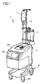
図1は、例えば、いわゆる連続式自己輸血システム(CATS:continuous autotransfusion system)として構成することができる血液処理装置1を示している。 FIG. 1 shows a blood processing apparatus 1 that can be configured, for example, as a so-called continuous autotransfusion system (CATS).
自己輸血システムは、例えば外科手術中又は外科手術後に患者から血液を採取する機能を果たすことができる。採取された血液は、自己輸血システム内で処理され、患者に再輸血するためにリサイクルされる。 An autotransfusion system can serve the function of drawing blood from a patient during or after surgery, for example. The collected blood is processed in an autotransfusion system and recycled for retransfusion to the patient.
このために、自己輸血システムを構成する図1の血液処理装置1は、患者から血液を採取する第1の貯留容器2を備える。血液は、チューブセットを通して、貯留容器2から血液処理装置1のハウジング10内に収容された洗浄チャンバー7(図2及び図3を参照)へ導かれる。血液は、洗浄チャンバー7によって処理され、処理の後、いわゆる再輸血バッグを構成する第2の貯留容器3内に回収される。血液は第2の貯留容器3から患者に再輸血することができる。
For this purpose, the blood processing apparatus 1 of FIG. 1 constituting the autotransfusion system includes a
図1の例において、ハウジング10は蓋100を備え、蓋100は、ハウジング10内に収容された洗浄チャンバー7にアクセスするため、またハウジング10内においてチューブセットを好適に配置するために開けることができる。ハウジング10は、血液処理装置1を操作するための制御コマンドを入力することができる制御パネル101を更に備える。
In the example of FIG. 1, the
ハウジング10は、例えば病院の手術室において血液処理装置1が移動可能であるように、車輪120を備える基部12上に配置される。
The
ハウジング10からはスタンド11が垂直に延在し、スタンド11上に、患者の血液を採取する第1の貯留容器2と、処理された血液を患者に再輸血するために回収する第2の貯留容器3とが配置される。
A
スタンド11上には、洗浄液用のバッグ4等の更なる容器(図2及び図3を参照)を配置することができる。
On the
血液処理装置1の機能面の構成は図2及び図3に示されているとおりである。 The functional configuration of the blood processing apparatus 1 is as shown in FIGS.
ハウジング10内に収容された洗浄チャンバー7は、回転軸Dを中心に回転可能であり、血液処理装置1の動作中、洗浄チャンバー7内で遠心分離プロセスを行うために回転軸Dを中心に回転する。洗浄チャンバー7はコネクタ70を備え、導管71がコネクタ70から別のコネクタ72に延びている。
The
機能に関して図3に示されているように、患者から採取された血液を収容する第1の貯留容器2と、患者に再輸血するための再輸血バッグを構成する第2の貯留容器3と、洗浄液(特に生理食塩水)用のバッグ4と、廃液バッグ5とが、異なるチューブセクションを含むチューブセットを介して洗浄チャンバー7に接続される。ここでは、図3に示されているように、異なるチューブセクションが洗浄チャンバー7の異なる場所に効果的に接続されている。
As shown in FIG. 3 in terms of function, a
図3に示されているように、第1の貯留容器2は、チューブセクション20を介してチューブセグメント60に接続され、チューブセグメント60において蠕動ポンプ機構600が作用する。ポンプ機構600によって、貯留容器2からチューブセクション21を通り、測定器8のチャンバー部材81及びチューブセクション22を介して洗浄チャンバー7に向かう流れがもたらされる。
As shown in FIG. 3, the
第2の貯留容器3は、チューブセクション30を介して測定器8のチャンバー部材81に接続され、またチューブセクション31を介してチューブセグメント61に接続され、チューブセグメント61において第2の蠕動ポンプ機構610が作用する。チューブセグメント61は、チューブセクション32を介して洗浄チャンバー7に接続される。
The
洗浄液用のバッグ4は、チューブセクション40を介してチューブセグメント62に接続され、チューブセグメント62において第3の蠕動ポンプ機構620が作用する。チューブセグメント62は、チューブセクション41を介して洗浄チャンバー7に接続される。
The bag 4 for cleaning liquid is connected to the
ポンプ機構600、610、620はそれぞれ、蠕動ポンプ作用を果たすように構成される。このために、血液処理装置1の動作中の各ポンプ機構600、610、620は回転運動Rを行い、この回転運動Rを通じてそれぞれのチューブセグメント60、61、62に作用する。
第1の貯留容器2に接続されたチューブセグメント60に作用するポンプ機構600と、同様に洗浄液用のバッグ4に接続されたチューブセグメント62に作用するポンプ機構620とは、第1の貯留容器2からの血液及びバッグ4からの洗浄液を洗浄チャンバー7に向かって輸送するように、洗浄チャンバー7に向かう流れ方向F1、F3に流れをもたらす。
The pump mechanism 600 acting on the
それに対して、処理された血液を患者に再輸血するために回収する第2の貯留容器3に接続されたチューブセグメント61に作用するポンプ機構610は、洗浄チャンバー7から第2の貯留容器3に向かう流れ方向F2に流れをもたらす。
On the other hand, the
廃液バッグ5は、チューブセクション50を介して洗浄チャンバー7に直接接続される。ここでは、チューブセクション50に作用するポンプ機構は伴わない。血液処理装置1の動作中、洗浄チャンバー7から廃液バッグ5に向かう流れ方向F4に流れがもたらされる。
The
図2に概略的に示されているように、3つのポンプ機構600、610、620が作用するチューブセグメント60、61、62は、本質的に既知の方法でポンプ台6に配置される。
As schematically shown in FIG. 2, the
血液処理装置1の動作中、血液は、貯留容器3において再輸血用にリサイクル及び回収するために、貯留容器2から洗浄チャンバー7内へ輸送され、洗浄チャンバー7内で処理される。ここでの処理は、洗浄チャンバー7において様々な段階で行われる。
During operation of the blood processing apparatus 1, blood is transported from the
第1の段階(いわゆる第1の分離段階)において、血液は、チューブセクション20〜22を通して血液を運ぶポンプ機構600のポンプ作用によって貯留容器2から洗浄チャンバー7内に入る。この最初の分離段階において、血液は、洗浄チャンバー7内でヘマトクリット値がおよそ80%に濃縮され、血漿、細胞片、白血球、血小板、抗凝血物質及び他の不所望の成分のほとんどが分離除去され、チューブセクション50を通して廃液バッグ5へと流される。この分離は、洗浄チャンバー7の回転運動によって遠心分離を起こし、それにより、血液を種々の構成要素に分離することで達成される。
In the first stage (the so-called first separation stage), blood enters the
第2の段階(いわゆる洗浄段階)中、血液の残りの成分、特に赤血球を、洗浄液用のバッグ4からポンプ機構620のポンプ作用によってチューブセクション40、41を通して運ばれる洗浄液、例えば生理食塩水に再懸濁する。洗浄段階において、血漿の更なる除去も行われる。
During the second stage (the so-called washing stage), the remaining components of the blood, in particular the red blood cells, are reconstituted into the washing liquid, eg saline, carried from the washing liquid bag 4 through the
第3の段階(いわゆる第2の分離段階)において、最終の分離を行う。この段階では、赤血球が約60%〜65%のヘマトクリット値濃度に凝縮される(packed)。この段階中において、洗浄段階中に添加された生理食塩水が再び除去される。 In the third stage (so-called second separation stage), the final separation is performed. At this stage, red blood cells are packed to a hematocrit value concentration of about 60% to 65%. During this stage, the saline added during the washing stage is again removed.
このようにして処理された血液は、チューブセクション32、31、30を通って洗浄チャンバー7を離れ、ポンプ機構610のポンプ作用によって貯留容器3内へ圧送され、そこで患者への再輸血のために回収される。
The blood thus treated leaves the
図2に示されているように、測定器8はチューブセット内に配置されている。測定器8は、貯留容器2から洗浄チャンバー7に向かって流れる血液中、及び洗浄チャンバー7を出て、再輸血用に処理された血液を回収する貯留容器3に向かって流れる血液中のヘマトクリット値を求める機能を果たす。測定器8は2つのチャンバー部材80、81を備え、2つのチャンバー部材80、81は、それぞれ入口ポート800、810及び出口ポート801、811を備える。
As shown in FIG. 2, the measuring
貯留容器2は、そのチューブセクション20、21を介して第1のチャンバー部材80の入口ポート800に接続される。一方、第1のチャンバー部材80の出口ポート801は、チューブセクション2を介して洗浄チャンバー7に接続される。さらに、洗浄チャンバー7は、チューブセクション32、31を介して第2のチャンバー部材81の入口ポート810に接続され、第2のチャンバー部材81の出口ポート811は、チューブセクション30を介して貯留容器3に接続される。
The
図3に示されているように、測定器8のチャンバー部材80、81は、各場合において、それぞれのポンプ機構600、610から下流に配置される。詳細には、貯留容器2から洗浄チャンバー7に向かう流れを起こすポンプ機構600は、第1のチャンバー部材80の入口ポート800の上流に配置される。処理された血液を貯留容器3内に運び、その処理された血液を患者に再輸血するためのポンプ機構610は、第2のチャンバー部材81の入口ポート810の上流に配置される。
As shown in FIG. 3, the
チャンバー部材80、81がそれぞれポンプ機構600、610から下流に配置されるため、各チャンバー部材80、81はそれぞれのポンプ機構600、610の圧力側に配置される。これには、ポンプ機構600、610の吸引により上流に生じる負圧に起因してポンプ機構600、610の上流に起こり得るキャビテーション効果を、このようなキャビテーション効果がチャンバー部材80、81内での測定に影響を与えないように最小限に低減することができるという有益な効果がある。
Since the
チャンバー部材80、81を備える測定器8は、貯留容器2から洗浄チャンバー7内に流れ、洗浄チャンバー7から貯留容器3内に流れる血液のヘマトクリット値を測定する機能を果たす。貯留容器2から洗浄チャンバー7に向かって流れる血液中のヘマトクリット値を測定することで、洗浄チャンバー7内への血流のヘマトクリットに応じてプロセスを制御することが可能である。洗浄チャンバー7から貯留容器3に向かって流れる処理された血液のヘマトクリットを測定することにより、処理された血液及びそこで得られたヘマトクリットについての情報が与えられ、所望のヘマトクリット値を得るためのプロセスパラメーターの調整が可能になる。
The measuring
言及したチャンバー部材80、81を備える測定器8は、チャンバー部材80、81を通って流れる血液のヘマトクリット値を測定する機能を果たす。ここでの測定は、図4及び図5に示されているように、超音波センサー素子92から対応するチャンバー部材80、81へと超音波パルスPを送信し、チャンバー部材80、81内に発生する反射信号を受信することによって行われる。チャンバー部材80、81内でのパルスPの伝播時間を調べることにより、チャンバー部材80、81内に収容される血液の密度を分析することができ、血液のヘマトクリットを導出することができる。
The measuring
図6及び図7A〜図7Cに示されているように、各チャンバー部材80、81は概して円筒形状である。各チャンバー部材80、81は、底壁803、813、周壁804、814及び頂壁805、815を備える。底壁803、813、周壁804、814及び頂壁805、815は、血液が通って流れる流れチャンバー802、812をともに画定する。
As shown in FIGS. 6 and 7A-7C, each
図4に戻ると、超音波センサー素子92は、チャンバー部材80の底壁803上に配置され、結合パッド920を介して底壁803に結合されている。超音波センサー素子92は、超音波パルスPを概して長手方向軸Lに沿って放出するように構成され、長手方向軸Lに沿って、流れチャンバー802が内部に収容されているチャンバー部材80が延在する。
Returning to FIG. 4, the
図5の曲線に示されているように、超音波パルスPをチャンバー部材80内に放出すると、チャンバー部材80の異なる面E1〜E5において反射が起こる。
As shown in the curve of FIG. 5, when the ultrasonic pulse P is emitted into the
詳細には、第1の反射は、結合パッド920及び底壁803の合間の面E2において起こる。第2の反射は、底壁803の流れチャンバー802側の面E3において起こる。第3の反射は、頂壁805の流れチャンバー802側の面E4において起こる。第4の反射は、頂壁805の外側を向く面E5において起こる。
Specifically, the first reflection occurs at the plane E2 between the
このような反射は、超音波センサー素子92に記録することができ、この記録された反射から、伝播時間を測定することができる。チャンバー部材80の幾何形状がわかっている場合、パルスPが伝播した材料の密度を導き出すことができる。次いで、流れチャンバー802内の血液の密度から、流れチャンバー802内に収容された血液のヘマトクリット値を導出することができる。
Such reflection can be recorded in the
測定器8を較正するために、密度がわかっている生理食塩水を用いてチャンバー部材80の様々な経路の長さを導出するため、最初の測定を行ってもよい。
In order to calibrate the
チャンバー部材80における様々な経路の長さは、異なる面E1〜E5における反射を確実な方法で識別することができるように選択するべきである。このために、底壁803及び頂壁805の厚さ並びに流れチャンバー802の長手方向軸Lに沿った長さを適切に選択するべきである。
The length of the various paths in the
結合パッド920は、チャンバー部材80の底壁803に対するセンサー素子92の有益な結合を得るように機能する。後述するように、チャンバー部材80の底壁803を、結合パッド920に対して好適な力(例えば15N超)で押し付けることが好適であり得る。
The
図6及び図7A、図7Bは、ウェブ86を介して互いに一体的に接続され、一体型測定ユニットを形成する2つのチャンバー部材80、81を備える測定器8の一実施形態を示している。ここでは、測定器8は、ハウジング85を形成する2つのハウジング部850、851から製造される。ハウジング部850、851は、例えば、プラスチック材料、例えばポリカーボネート等のポリマーから射出成形することによって別個に製造することができ、その後、ともに接合して測定器8を形成することができる。
6 and 7A, 7B show an embodiment of the measuring
各チャンバー部材80、81は、長手方向軸Lに沿って長手方向に延在する。ここでは、チャンバー部材80、81の長手方向軸Lは、互いに対して平行に延びている。各チャンバー部材80、81は、それぞれの長手方向軸Lの周りに周方向に延在する周壁804、814を備え、概して円筒形の2つのチャンバー部材80、81が形成されるようになっている。
Each
各チャンバー部材80、81は、入口ポート800、810及び出口ポート801、811を備える。各場合における入口ポート800、810は底壁803、813の近位に配置され、一方、各場合における出口ポート801、811は頂壁805、815の近位に配置される。
Each
図7Bに示されているように、入口ポート800、810は、それぞれの流れチャンバー802、812内の底壁803、813のすぐ内側に開口し、一方、出口ポート801、811はそれぞれの流れチャンバー内の頂壁805、815のすぐ内側に開口している。
As shown in FIG. 7B, the
図7Aに示されているように、各チャンバー部材80、81に対する入口ポート800、810及び出口ポート801、811は、それぞれのチャンバー部材80、81の周壁804、814に配置され、長手方向軸Lに沿って互いにずらされている。したがって、入口ポート800、810及び出口ポート801、811は、長手方向軸Lに対して異なる高さに配置されている。
As shown in FIG. 7A, the
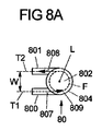
さらに、第1のチャンバー部材80に関して図8A、また第2のチャンバー部材81に関して図8Bに概略的に示されているように、入口ポート800、810及び出口ポート801、811は、それぞれ流れチャンバー802、812内への流れ又は流れチャンバー802、812から出る流れを可能にする導管807、808、817、818をそれぞれ備える。導管807、808、817、818は、長手方向軸Lとは交わらず、したがって長手方向軸Lとはねじれの位置をなす接線方向軸T1、T2に沿って延在する。
Further, as schematically shown in FIG. 8A for the
詳細には、図8Aに示されているように、第1のチャンバー部材80の入口ポート800の導管807は、長手方向軸Lとは交わらない第1の接線方向軸T1に沿って延在する。同様に、第1のチャンバー部材80の出口ポート801の導管808は、第2の接線方向軸T2に沿って延在する。第2の接線方向軸T2は、第1の接線方向軸T1に対して平行に延び、第1の接線方向軸T1から変位量Wだけずれている。
Specifically, as shown in FIG. 8A, the
第1のチャンバー部材80では、血液は、第1の方向において流れチャンバー802内へ流れ、反対の第2の方向において出口ポート801を通って流れチャンバー802を離れる。導管807、808が接線方向T1、T2に沿って延在することに起因して、入口ポート800及び出口ポート801は、接線方向に流れチャンバー802内へと開口しており、流れFが流れチャンバー802の内面809に対して接線方向に流れチャンバー802へ入り、同様に、出口ポート801を通って接線方向に流れチャンバー802を出るようになっている。
In the
長手方向軸Lに沿った入口ポート800及び出口ポート801の変位量の組合せにより、図8Aに示されているように、流れチャンバー802内に乱流Fが発生する。このような乱流Fは、流れチャンバー802内における沈殿のリスクを低減する。
The combination of the displacement amount of the
第2のチャンバー部材81に関して図8Bに示されているように、第2のチャンバー部材81の入口ポート810及び出口ポート811の導管817、818は、同様に接線方向に流れチャンバー812内へと開口し、流れチャンバー812において乱流Fを引き起こす。ここでは、接線方向軸T1、T2が互いに一致しているが(上から見た場合)、入口ポート810及び出口ポート811は、第2のチャンバー部材81の周壁814から互いに反対側に延在する。
As shown in FIG. 8B for the
図8C及び図8Dは、異なるチャンバー部材80、81の入口ポート800、810及び出口ポート801、811のそれぞれの長手方向軸Lに沿った長手方向変位を示している。双方のチャンバー部材80、81に関して、入口ポート800、810及び出口ポート801、811が延在する場合に沿う接線方向軸T1、T2は、互いに対して変位量Hだけずれている。
8C and 8D show the longitudinal displacement along the longitudinal axis L of each of the
図6及び図7Aに見られるように、各チャンバー部材80、81は、周壁804、814の外側に平坦面806、816を有し、平坦面806、816は、同じ平面内に存在するように位置合わせされる。図7Cの断面図に見られるように、平坦面806、816の領域において、周壁804、814は低減された壁厚Bを有する。
As seen in FIGS. 6 and 7A, each
各チャンバー部材80、81の平坦面806、816は、後述するように、赤外線センサー素子と相互作用する機能を果たす。平坦面806、816を介して、流れチャンバー802、812内の温度を、平坦面806、816から放出される赤外線を受信することによって測定することができる。
The
測定器8は、測定器8を手で把持するためのハンドル84を備える。ハンドル84は、チャンバー部材80、81の頂壁805、815を形成するハウジング部851に配置される。
The measuring
測定器8は、貯留容器2と、貯留容器3と、洗浄液用のバッグ4と、廃液バッグ5とを洗浄チャンバー7に接続するチューブセクションによって形成されるチューブセットの一部である。特に、自己輸血セットは使い捨てとすることができ、洗浄チャンバー7と、ポンプ機構600〜620と相互作用するチューブセグメント60〜62を含む、洗浄チャンバー7をそれぞれのバッグ又は容器2〜5に接続する全てのチューブセクションとからなることができる。
The measuring
図1に概略的に示されているように、血液処理装置1は、ハウジング10内に洗浄チャンバー7を収納し、また、測定器8を収納するホルダー器具9を備える。そのようなホルダー器具9の一実施形態は図9〜図11に示されている。
As schematically shown in FIG. 1, the blood processing apparatus 1 includes a
図9〜図11の実施形態において、ホルダー器具9は基部90及び閉鎖部材91を備え、閉鎖部材91は、基部90に配置されるとともに、基部90に対して旋回軸910を中心に旋回可能である。基部90は収納開口900を形成し、チャンバー部材80、81を備える測定器8を収納開口900内に挿入することができる。図9及び図10に示されている挿入位置において、測定器8は収納開口900に収まるようになっている。
9 to 11, the
基部90は、図11に示されるとともに図12に概略的に示されているように、第1の傾斜面904及び第2の傾斜面903を有する。傾斜面903、904は、互いに対して垂直に配置され、それぞれチャンバー部材80、81の底壁803、813又は周壁804、814の平坦面806、816に当接する機能を果たす。
As shown in FIG. 11 and schematically shown in FIG. 12, the
ここでは、第1の傾斜面904に2つの超音波センサー素子92、93が配置され、2つの超音波センサー素子92、93は結合パッド920、930を備え、結合パッド920、930は外側の方を向いている。第2の傾斜面903には2つの赤外線窓940、950が配置され、2つの赤外線窓940、950は、赤外線に対して(少なくとも部分的に)透明であり、赤外線窓940、950の後ろに位置する赤外線センサー94、95用の窓を形成する。これは図12に概略的に示されている。
Here, two
チャンバー部材80、81を備える測定器8は、その挿入位置において、チャンバー部材80、81の底壁803、813が第1の傾斜面904に面し、結合パッド920、930と接触するように収納開口900内に挿入される。同時に、チャンバー部材80、81は平坦面806、816によって第2の傾斜面903に当接し、第1のチャンバー部材80の平坦面806が赤外線窓940に面し、第2のチャンバー部材81の平坦面816が赤外線窓950に面するようになっている。
The measuring
測定器8を収納開口900内に挿入するために、図10及び図11に示されているように閉鎖部材91を開くことができる。測定器8を収納開口900内に挿入した後、図9に示されているように、閉鎖部材91の前縁部が基部90の縁部セクション901に位置することになるように閉鎖部材91を閉鎖する。閉鎖位置において、閉鎖部材91は係止要素914を介して基部90に対して係止される。この場合、係止要素914が基部90の対応する係止要素902に係合し、閉鎖部材91と基部90との間に確実な係止が達成されるようになっている。
In order to insert the measuring
閉鎖部材91の閉鎖位置において、収納開口900の内側に面する閉鎖部材91の内面から突出する固定要素912、913は、チャンバー部材80、81の頂壁805、815に当接する。固定要素912、913によって、長手方向軸Lに沿ってチャンバー部材80、81に力が加わり、それにより、チャンバー部材80、81は、超音波センサー素子92、93の結合パッド920、930に対して所定の力で押し付けられる。このようにして、チャンバー部材80、81の底壁803、813に対するセンサー素子92、93の有益な結合が達成される。
In the closed position of the closing
図9及び図10に示されているように、接続ライン921、931は、センサー素子92、93に接続され、センサー素子92、93を制御ユニット96に電気的に接続する機能を果たす。これは図13に示されている。センサー素子92、93は、接続ライン921、931を介して励起されて超音波パルスPを発生し、また、センサー素子92、93において受信された反射信号は、センサー信号として制御ユニット96に送信される。
As shown in FIGS. 9 and 10, the
制御ユニット96において、それぞれのチャンバー部材80、81を通って流れる血液のヘマトクリット値を求めるために信号処理を行う。制御ユニット96は、制御ユニット96に給電する電源ライン960と、他のユニットにデータを提供するデータ出力ライン961とを備える。
In the control unit 96, signal processing is performed to determine the hematocrit value of the blood flowing through the
赤外線センサー素子94、95を用いて、チャンバー部材80、81内の血液の温度が求められる。図12に示されているように、各赤外線センサー素子94、95は、センサー信号を制御ユニット96に送信する接続ライン941(図12では赤外線センサー素子94のみに対して示されている)に接続することができる。
Using the
図12に示されているように、チャンバー部材80、81の長手方向軸Lは、重力方向Gに対して角度αで配置されている。各チャンバー部材80、81の出口ポート801、811はそれぞれのチャンバー部材80、81の頂壁805、815に配置されているため、流れチャンバー802、812内の気泡は流れチャンバー802、812内を上昇することができ、気泡が流れチャンバー802、812から除去されるようにそれぞれの出口ポート801、811から一掃することができる。したがって、チャンバー部材80、81内における測定は気泡の存在によって妨害されない。
As shown in FIG. 12, the longitudinal axis L of the
ここでは、各チャンバー部材80、81の出口ポート801、811は、ホルダー器具9に挿入される場合、重力方向Gに対して流れチャンバー802、812の最高点に配置されることが有益である。これは図12に示されている。これにより、流れチャンバー802、812において重力方向Gに逆らって上昇する気泡が、出口ポート801、811を通って流れチャンバー802、812を出ることができ、流れチャンバー802、812内に捕捉されないことが確実になる。
Here, the
閉鎖部材91は開口911を有し、測定器8が収納開口900に挿入され、閉鎖部材91が閉鎖された場合、ハンドル84は開口911から延出する。これは図9に示されている。したがって、使用者は、閉鎖部材91が完全に閉鎖するまで、ハンドル84を把持することによって測定器8を保持することができる。これにより、測定器8をホルダー器具9に正しい方法で挿入することが容易になる。
The closing
ホルダー器具9は、測定器8を単一の位置においてのみ収納開口900に挿入することができるように構成されることが有益である。これにより、熟練していない使用者でも、測定器8をホルダー器具9に正しく挿入することが確実になる。
The
本発明の根底にある構想は、上述した実施形態に限定されず、全く異なる実施形態においても用いることができる。 The concept underlying the present invention is not limited to the embodiments described above, and can be used in completely different embodiments.
詳細には、本発明は、自己輸血システムに限定されず、血液を処理する他の医療用システムにおいても用いることができる。 Specifically, the present invention is not limited to autotransfusion systems, but can be used in other medical systems that process blood.
1 血液処理装置
10 ハウジング
100 蓋
101 制御パネル
11 スタンド
12 基部
120 車輪
2 貯留容器
20〜22 チューブセクション
3 再輸血バッグ
30〜32 チューブセクション
4 洗浄液用のバッグ
40、41 チューブセクション
5 廃液バッグ
50 接続チューブ
6 ポンプ台
60〜62 チューブセグメント
600〜620 ポンプ機構
7 洗浄チャンバー
70 コネクタ
71 導管
72 コネクタ
8 測定器
80、81 チャンバー部材
800、810 入口ポート
801、811 出口ポート
802、812 流れチャンバー
803、813 底壁
804、814 周壁
805、815 頂壁
806、816 平坦面
807、817 導管
808、818 導管
809、819 内面
84 ハンドル
85 ハウジング
850、851 ハウジング部
86 ウェブ
9 ホルダー器具
90 基部
900 収納開口
901 縁部セクション
902 係止要素
903、904 傾斜面
91 閉鎖部材
910 旋回軸
911 開口
912、913 固定要素
914 係止要素
92、93 超音波センサー素子
920、930 結合パッド
921、931 接続ライン
94、95 赤外線センサー素子
940、950 赤外線窓
941、951 接続部
96 制御ユニット
960、961 接続部
α 角度
B 壁厚
D 回転軸
E1〜E5 面
F 流れ
F1〜F4 流れ方向
G 重力方向
H 高さ
L 長手方向軸
P パルス
R 回転運動
T1、T2 接線方向軸
W 幅
DESCRIPTION OF SYMBOLS 1 Blood processing apparatus 10 Housing 100 Cover 101 Control panel 11 Stand 12 Base 120 Wheel 2 Storage container 20-22 Tube section 3 Retransfusion bag 30-32 Tube section 4 Bag for washing | cleaning liquid 40, 41 Tube section 5 Waste liquid bag 50 Connection tube 6 Pump stand 60-62 Tube segment 600-620 Pump mechanism 7 Cleaning chamber 70 Connector 71 Conduit 72 Connector 8 Measuring instrument 80, 81 Chamber member 800, 810 Inlet port 801, 811 Outlet port 802, 812 Flow chamber 803, 813 Bottom wall 804, 814 Peripheral wall 805, 815 Top wall 806, 816 Flat surface 807, 817 Conduit 808, 818 Conduit 809, 819 Inner surface 84 Handle 85 Housing 850, 8 DESCRIPTION OF SYMBOLS 1 Housing part 86 Web 9 Holder apparatus 90 Base 900 Storage opening 901 Edge part 902 Locking element 903,904 Inclined surface 91 Closure member 910 Rotating shaft 911 Opening 912,913 Fixing element 914 Locking element 92,93 Ultrasonic sensor element 920, 930 Bond pad 921, 931 Connection line 94, 95 Infrared sensor element 940, 950 Infrared window 941, 951 Connection 96 Control unit 960, 961 Connection α angle B Wall thickness D Rotating shaft E1-E5 Surface F Flow F1- F4 Flow direction G Gravity direction H Height L Longitudinal axis P Pulse R Rotational motion T1, T2 Tangential axis W Width
Claims (15)
前記測定器(8)を保持するホルダー器具(9)と、
前記ホルダー器具(9)の超音波センサー素子(92、93)と、を備える血液処理装置(1)であって、
前記少なくとも1つのチャンバー部材(80、81)は、長手方向軸(L)に沿って延在し、該長手方向軸(L)の周りに延在する周壁(804、814)と、底壁(803、813)及び頂壁(805、815)とを備え、これらの壁はともに流れチャンバー(802、812)を画定し、
前記少なくとも1つのチャンバー部材(80、81)は、前記流れチャンバー(802、812)内への血液流体の流れを可能にする入口ポート(800、810)と、前記流れチャンバー(802、812)から出る血液流体の流れを可能にする出口ポート(801、811)とを更に備え、
前記ホルダー器具(9)は、前記測定器(8)を収納する収納開口(900)を備える基部(90)と、前記測定器(8)を前記収納開口(900)内の挿入位置に係止する、前記基部(90)に可動に配置された閉鎖部材(91)とを備え、
前記超音波センサー素子(92、93)は、前記基部(90)に配置され、前記流れチャンバー(802、812)内の血液流体のヘマトクリット値を測定する超音波センサー信号(P)を生成するようになっており、
前記超音波センサー素子(92、93)は、前記測定器(8)の前記挿入位置において、前記少なくとも1つのチャンバー部材(80、81)の前記底壁(803、813)に面し、該底壁(803、813)を通して前記流れチャンバー(802、812)内に前記超音波センサー信号(P)を送信することを特徴とする、血液処理装置。 A meter (8) having at least one chamber member (80, 81) for receiving blood fluid;
A holder device (9) for holding the measuring device (8);
A blood treatment device (1) comprising ultrasonic sensor elements (92, 93) of the holder device (9),
The at least one chamber member (80, 81) extends along a longitudinal axis (L), a peripheral wall (804, 814) extending around the longitudinal axis (L), and a bottom wall ( 803, 813) and a top wall (805, 815), these walls together defining a flow chamber (802, 812),
The at least one chamber member (80, 81) has an inlet port (800, 810) that allows blood fluid flow into the flow chamber (802, 812) and from the flow chamber (802, 812). An outlet port (801, 811) that allows the flow of the exiting blood fluid;
The holder device (9) includes a base (90) having a storage opening (900) for storing the measuring instrument (8), and the measuring instrument (8) is locked at an insertion position in the storage opening (900). A closure member (91) movably disposed on the base (90),
The ultrasonic sensor element (92, 93) is disposed on the base (90) and generates an ultrasonic sensor signal (P) for measuring a hematocrit value of blood fluid in the flow chamber (802, 812). And
The ultrasonic sensor element (92, 93) faces the bottom wall (803, 813) of the at least one chamber member (80, 81) at the insertion position of the measuring instrument (8). A blood processing apparatus, wherein the ultrasonic sensor signal (P) is transmitted into the flow chamber (802, 812) through a wall (803, 813).
該結合パッド(920、930)は、前記測定器(8)の前記挿入位置において、前記少なくとも1つのチャンバー部材(80、81)の前記底壁(803、813)に当接することを特徴とする、請求項1又は2に記載の血液処理装置。 The ultrasonic sensor element (92, 93) includes a bonding pad (920, 930),
The bonding pads (920, 930) are in contact with the bottom walls (803, 813) of the at least one chamber member (80, 81) at the insertion position of the measuring device (8). The blood processing apparatus according to claim 1 or 2.
該赤外線センサー素子(94、95)は、前記測定器(8)の前記挿入位置において、前記少なくとも1つのチャンバー部材(80、81)の前記周壁(804、814)に面することを特徴とする、請求項1〜5のいずれか1項に記載の血液処理装置。 The holder device (9) comprises an infrared sensor element (94, 95) disposed on the base (90) for measuring the temperature of the blood fluid in the flow chamber (802, 812),
The infrared sensor element (94, 95) faces the peripheral wall (804, 814) of the at least one chamber member (80, 81) at the insertion position of the measuring instrument (8). The blood processing apparatus according to any one of claims 1 to 5.
前記超音波センサー素子(92、93)は、前記第1の傾斜面(904)に配置され、
前記赤外線センサー素子(94、95)は、前記第2の傾斜面(903)に配置されることを特徴とする、請求項6に記載の血液処理装置。 The base (90) has a first inclined surface (904) and a second inclined surface (903) extending in a direction transverse to the first inclined surface (904),
The ultrasonic sensor elements (92, 93) are disposed on the first inclined surface (904),
The blood processing apparatus according to claim 6, wherein the infrared sensor element (94, 95) is disposed on the second inclined surface (903).
該平坦面(806、816)は、前記測定器(8)の前記挿入位置において、前記第2の傾斜面(903)に当接することを特徴とする、請求項7に記載の血液処理装置。 The peripheral wall (804, 814) of the at least one chamber member (80, 81) has a flat surface (806, 816) on the outside not facing the flow chamber (802, 812);
The blood processing apparatus according to claim 7, wherein the flat surface (806, 816) abuts on the second inclined surface (903) at the insertion position of the measuring instrument (8).
前記赤外線センサー素子(94、95)は、前記測定器(8)から見ると前記赤外線窓(940、950)の後ろに位置することを特徴とする、請求項7〜9のいずれか1項に記載の血液処理装置。 The second inclined surface (903) includes an infrared window (940, 950) for transmitting infrared rays,
10. The infrared sensor element (94, 95) is located behind the infrared window (940, 950) when viewed from the measuring instrument (8), according to any one of claims 7-9. The blood processing apparatus as described.
前記ホルダー器具(9)は、前記測定器(8)の前記挿入位置において前記第1のチャンバー部材(80)の前記底壁(803)に面する第1の超音波センサー素子(92)と、前記測定器(8)の前記挿入位置において前記第2のチャンバー部材(81)の前記底壁(813)に面する第2の超音波センサー素子(93)とを備えることを特徴とする、請求項1〜10のいずれか1項に記載の血液処理装置。 The measuring instrument (8) includes a first chamber member (80) and a second chamber member (81) connected to each other,
The holder device (9) includes a first ultrasonic sensor element (92) facing the bottom wall (803) of the first chamber member (80) at the insertion position of the measuring instrument (8); A second ultrasonic sensor element (93) facing the bottom wall (813) of the second chamber member (81) at the insertion position of the measuring instrument (8). Item 11. The blood processing apparatus according to any one of Items 1 to 10.
前記測定器(8)の前記挿入位置において、前記開口(911)から前記ハンドル(84)が延出することを特徴とする、請求項14に記載の血液処理装置。
The closure member (91) has an opening (911);
The blood processing device according to claim 14, characterized in that the handle (84) extends from the opening (911) at the insertion position of the measuring device (8).
Applications Claiming Priority (3)
| Application Number | Priority Date | Filing Date | Title |
|---|---|---|---|
| EP14182869 | 2014-08-29 | ||
| EP14182869.9 | 2014-08-29 | ||
| PCT/EP2015/067813 WO2016030147A1 (en) | 2014-08-29 | 2015-08-03 | A blood processing apparatus comprising a holder device for a measurement device |
Publications (2)
| Publication Number | Publication Date |
|---|---|
| JP2017526441A JP2017526441A (en) | 2017-09-14 |
| JP6560744B2 true JP6560744B2 (en) | 2019-08-14 |
Family
ID=51421977
Family Applications (1)
| Application Number | Title | Priority Date | Filing Date |
|---|---|---|---|
| JP2017511607A Active JP6560744B2 (en) | 2014-08-29 | 2015-08-03 | Blood processing apparatus comprising a holder device for a measuring instrument |
Country Status (5)
| Country | Link |
|---|---|
| US (1) | US10653345B2 (en) |
| EP (1) | EP3193956B1 (en) |
| JP (1) | JP6560744B2 (en) |
| CN (1) | CN106604680B (en) |
| WO (1) | WO2016030147A1 (en) |
Families Citing this family (5)
| Publication number | Priority date | Publication date | Assignee | Title |
|---|---|---|---|---|
| EP3838308A1 (en) | 2014-04-29 | 2021-06-23 | Outset Medical, Inc. | Dialysis system and methods |
| EP3500317B1 (en) | 2016-08-19 | 2022-02-23 | Outset Medical, Inc. | Peritoneal dialysis system and methods |
| WO2018078737A1 (en) * | 2016-10-26 | 2018-05-03 | 株式会社島津製作所 | Flow-through vial and automatic sampler |
| CN112472894B (en) * | 2019-09-12 | 2024-07-09 | 费森尤斯医疗护理德国有限责任公司 | System and method for leak-free connection of a concentrate container to a blood processing device |
| CN110554087A (en) * | 2019-09-18 | 2019-12-10 | 哈尔滨工业大学 | Device for detecting blood clots |
Family Cites Families (32)
| Publication number | Priority date | Publication date | Assignee | Title |
|---|---|---|---|---|
| US4479762A (en) * | 1982-12-28 | 1984-10-30 | Baxter Travenol Laboratories, Inc. | Prepackaged fluid processing module having pump and valve elements operable in response to applied pressures |
| US6740036B1 (en) * | 2000-07-18 | 2004-05-25 | Lian-Pin Lee | Optical and ultrasound probe for monitoring blood volume changes |
| US5453576A (en) * | 1994-10-24 | 1995-09-26 | Transonic Systems Inc. | Cardiovascular measurements by sound velocity dilution |
| AUPM934994A0 (en) * | 1994-11-09 | 1994-12-01 | Commonwealth Scientific And Industrial Research Organisation | Particle property measurement |
| US5983120A (en) * | 1995-10-23 | 1999-11-09 | Cytometrics, Inc. | Method and apparatus for reflected imaging analysis |
| SE513522C2 (en) | 1998-09-10 | 2000-09-25 | Gambro Ab | Device for monitoring a fluid tube |
| US6144444A (en) | 1998-11-06 | 2000-11-07 | Medtronic Avecor Cardiovascular, Inc. | Apparatus and method to determine blood parameters |
| US6875191B2 (en) | 1999-09-03 | 2005-04-05 | Baxter International Inc. | Blood processing systems and methods that alternate flow of blood component and additive solution through an in-line leukofilter |
| US7011761B2 (en) * | 1999-09-03 | 2006-03-14 | Baxter International Inc. | Red blood cell processing systems and methods which control red blood cell hematocrit |
| JP4382322B2 (en) * | 2000-03-09 | 2009-12-09 | カリディアンビーシーティ、インコーポレイテッド | Extracorporeal blood treatment equipment |
| IT1318444B1 (en) | 2000-04-03 | 2003-08-25 | Dideco Spa | INTRAOPERATIVE SELF-TRANSFUSION DEVICE. |
| BR0106942A (en) | 2000-07-07 | 2002-06-11 | Baxter Int | Medical system, method and apparatus using mems |
| DE10143137C1 (en) * | 2001-09-03 | 2003-04-17 | Fresenius Medical Care De Gmbh | Measuring device and method for determining parameters of medical liquids and method for calibrating such a device |
| JP2003075304A (en) | 2001-09-07 | 2003-03-12 | Sysmex Corp | Automatic blood analyzer and device for stopping pipette for pipette drive device used for the same |
| AU2003228582A1 (en) * | 2002-04-19 | 2003-11-03 | Mission Medical, Inc. | Integrated automatic blood processing unit |
| DE10224750A1 (en) | 2002-06-04 | 2003-12-24 | Fresenius Medical Care De Gmbh | Device for the treatment of a medical fluid |
| US7838296B2 (en) | 2002-08-28 | 2010-11-23 | Separation Technology, Inc. | Methods and apparatus for ultrasonic determination of red blood cell indices |
| US6849039B2 (en) | 2002-10-24 | 2005-02-01 | Baxter International Inc. | Blood processing systems and methods for collecting plasma free or essentially free of cellular blood components |
| ES2686068T3 (en) * | 2003-11-05 | 2018-10-16 | Separation Technology, Inc. | Disposable fluid sample collection device |
| CA2589197C (en) * | 2003-11-26 | 2012-03-20 | Separation Technology, Inc. | Method and apparatus for ultrasonic determination of hematocrit and hemoglobin concentrations |
| US7727194B2 (en) * | 2004-08-31 | 2010-06-01 | Ethicon Endo-Surgery, Inc. | Drug delivery cassette |
| JP4944093B2 (en) | 2006-03-10 | 2012-05-30 | 川澄化学工業株式会社 | Blood characteristic measurement probe, circulatory system artificial organ and artificial lung |
| US8631683B2 (en) * | 2007-02-06 | 2014-01-21 | Fresenius Medical Care Holdings, Inc. | Dialysis systems including non-invasive multi-function sensor systems |
| US7661294B2 (en) * | 2007-09-21 | 2010-02-16 | Cosense, Inc. | Non-invasive multi-function sensor system |
| US8417311B2 (en) * | 2008-09-12 | 2013-04-09 | Optiscan Biomedical Corporation | Fluid component analysis system and method for glucose monitoring and control |
| US8597505B2 (en) * | 2007-09-13 | 2013-12-03 | Fresenius Medical Care Holdings, Inc. | Portable dialysis machine |
| EP2217301A2 (en) * | 2007-10-12 | 2010-08-18 | DEKA Products Limited Partnership | Systems, devices and methods for cardiopulmonary treatment and procedures |
| DE102010001605A1 (en) | 2010-02-04 | 2011-08-04 | Fresenius Medical Care Deutschland GmbH, 61352 | Sensor system for filling level detection of a fluid in a vessel |
| US9002655B2 (en) * | 2010-05-03 | 2015-04-07 | Gambro Lundia Ab | Medical apparatus for extracorporeal blood treatment and method for determining a blood parameter value in a medical apparatus thereof |
| US9283315B2 (en) * | 2011-02-08 | 2016-03-15 | Fresenius Medical Care Holdings, Inc. | Apparatus and method for real time measurement of a constituent of blood to monitor blood volume |
| DE102012104461A1 (en) | 2012-05-23 | 2013-12-12 | B. Braun Avitum Ag | Medical device for extracorporeal blood treatment with multiple sensor units |
| EP4406654A2 (en) * | 2015-01-12 | 2024-07-31 | Instrumentation Laboratory Company | Spatial separation of particles in a particle containing solution for biomedical sensing and detection |
-
2015
- 2015-08-03 EP EP15744248.4A patent/EP3193956B1/en active Active
- 2015-08-03 US US15/503,152 patent/US10653345B2/en active Active
- 2015-08-03 JP JP2017511607A patent/JP6560744B2/en active Active
- 2015-08-03 CN CN201580045794.6A patent/CN106604680B/en active Active
- 2015-08-03 WO PCT/EP2015/067813 patent/WO2016030147A1/en active Application Filing
Also Published As
| Publication number | Publication date |
|---|---|
| CN106604680B (en) | 2020-03-20 |
| WO2016030147A1 (en) | 2016-03-03 |
| EP3193956A1 (en) | 2017-07-26 |
| EP3193956B1 (en) | 2018-11-07 |
| US10653345B2 (en) | 2020-05-19 |
| CN106604680A (en) | 2017-04-26 |
| US20170227438A1 (en) | 2017-08-10 |
| JP2017526441A (en) | 2017-09-14 |
Similar Documents
| Publication | Publication Date | Title |
|---|---|---|
| JP6560744B2 (en) | Blood processing apparatus comprising a holder device for a measuring instrument | |
| JP5623383B2 (en) | Measurement of fine particles in a liquid using reflected light | |
| US8040493B2 (en) | Thermal flow meter | |
| KR101923627B1 (en) | Portable dialysis machine | |
| JP6517023B2 (en) | Blood purification device | |
| CA2706409C (en) | Disposable extracorporeal blood circuit and apparatus for the extracorporeal treatment of blood | |
| EP3397302B1 (en) | A dialysis machine | |
| US11826503B2 (en) | Medical fluid cassettes and related systems | |
| KR20160047428A (en) | Manifold diaphragms | |
| US20130334420A1 (en) | Process for Predicting Hematocrit of Whole Blood Using IR Light | |
| JP6560743B2 (en) | Blood processing apparatus equipped with a measuring device | |
| JP6533826B2 (en) | Tube set used in blood processing apparatus | |
| ES2976019T3 (en) | Non-invasive sensor to determine the heartbeat and/or cardiac rhythm in a segment of an extracorporeal blood circuit | |
| IT201900016787A1 (en) | Non-invasive sensor for determining a heartbeat and / or heart rate in an extracorporeal segment of a conduit for an extracorporeal blood circuit. | |
| CN109152876A (en) | external function device |
Legal Events
| Date | Code | Title | Description |
|---|---|---|---|
| A621 | Written request for application examination |
Free format text: JAPANESE INTERMEDIATE CODE: A621 Effective date: 20180801 |
|
| A977 | Report on retrieval |
Free format text: JAPANESE INTERMEDIATE CODE: A971007 Effective date: 20190426 |
|
| A131 | Notification of reasons for refusal |
Free format text: JAPANESE INTERMEDIATE CODE: A131 Effective date: 20190514 |
|
| A521 | Request for written amendment filed |
Free format text: JAPANESE INTERMEDIATE CODE: A523 Effective date: 20190624 |
|
| TRDD | Decision of grant or rejection written | ||
| A01 | Written decision to grant a patent or to grant a registration (utility model) |
Free format text: JAPANESE INTERMEDIATE CODE: A01 Effective date: 20190709 |
|
| A61 | First payment of annual fees (during grant procedure) |
Free format text: JAPANESE INTERMEDIATE CODE: A61 Effective date: 20190719 |
|
| R150 | Certificate of patent or registration of utility model |
Ref document number: 6560744 Country of ref document: JP Free format text: JAPANESE INTERMEDIATE CODE: R150 |
|
| R250 | Receipt of annual fees |
Free format text: JAPANESE INTERMEDIATE CODE: R250 |
|
| R250 | Receipt of annual fees |
Free format text: JAPANESE INTERMEDIATE CODE: R250 |
|
| R250 | Receipt of annual fees |
Free format text: JAPANESE INTERMEDIATE CODE: R250 |