JP6560563B2 - Image processing apparatus, image processing method, and computer program - Google Patents
Image processing apparatus, image processing method, and computer program Download PDFInfo
- Publication number
- JP6560563B2 JP6560563B2 JP2015164180A JP2015164180A JP6560563B2 JP 6560563 B2 JP6560563 B2 JP 6560563B2 JP 2015164180 A JP2015164180 A JP 2015164180A JP 2015164180 A JP2015164180 A JP 2015164180A JP 6560563 B2 JP6560563 B2 JP 6560563B2
- Authority
- JP
- Japan
- Prior art keywords
- image
- frequency component
- input
- frequency
- low
- Prior art date
- Legal status (The legal status is an assumption and is not a legal conclusion. Google has not performed a legal analysis and makes no representation as to the accuracy of the status listed.)
- Active
Links
Images


Description
本発明は画像処理装置及び画像処理方法、コンピュータプログラムに関する。 The present invention relates to an image processing apparatus, an image processing method, and a computer program.
従来から、入力画像と出力画像の解像度を変更することが知られている。例えば、撮影した解像度と記録する解像度を異なるものにしたり、放送されている動画信号をその解像度と異なる解像度の表示装置に表示するために縮小処理あるいは拡大処理と呼ばれる画像変換処理を行ったりすることが知られている。また、プロジェクターを斜め方向から投射したり曲面のスクリーンに投射するために、幾何変形処理と呼ばれる画像変換処理を行うことが知られている。また従来から、デジタルカメラ、デジタルビデオカメラ、フラットベッドスキャナーなどで、光学的に結像された対象物をデジタル撮像素子でデジタル画像化することが、行われている。以下、これらの画像変換処理をまとめて変換処理と呼ぶ。 Conventionally, it is known to change the resolution of an input image and an output image. For example, the captured resolution may be different from the recorded resolution, or image conversion processing called reduction processing or enlargement processing may be performed to display a broadcast video signal on a display device having a resolution different from the resolution. It has been known. In addition, it is known to perform an image conversion process called a geometric deformation process in order to project a projector from an oblique direction or onto a curved screen. Further, conventionally, a digital image is formed by using a digital image sensor on an object that has been optically imaged by a digital camera, a digital video camera, a flatbed scanner, or the like. Hereinafter, these image conversion processes are collectively referred to as a conversion process.
このような変換処理のうち、画像変形処理を行う場合に、画像の内容によってはモアレと呼ばれる妨害(ノイズ)が発生することがある。モアレとは干渉縞ともいい、画像内の繰り返し模様とサンプリング周波数の間に起こる空間周波数のうなり現象である。モアレが発生すると非常に目立つので、画質を維持するためにモアレの発生を防止する必要がある。また変換処理のうち、デジタル画像化処理を行う場合にも、対象物の内容によっては、モアレが発生することがあるので、モアレの発生を防止する必要がある。またデジタル撮像素子のRGB素子の配列がBayer配列と呼ばれる並びになっている場合には、モアレだけでなく偽色と言われる妨害が発生することがあるので、これも防止する必要がある。 Among such conversion processes, when performing an image transformation process, interference (noise) called moire may occur depending on the contents of the image. Moire is also called interference fringes, and is a spatial frequency beat phenomenon that occurs between a repetitive pattern in an image and a sampling frequency. Since moiré is very noticeable, it is necessary to prevent moiré in order to maintain image quality. Also, when performing digital imaging processing among the conversion processing, moire may occur depending on the content of the object, so it is necessary to prevent the occurrence of moire. Further, when the arrangement of the RGB elements of the digital image sensor is a so-called Bayer arrangement, there is a possibility that not only moire but also a false color may occur, which must be prevented.
例えば、幾何変形処理を含む縮小処理の場合には、入力画像にローパスフィルター(以下、LPFと略す)を適用して、高周波領域を削減してから、幾何変形処理を含む縮小処理を行うことにより、モアレの発生を防ぐことが知られている。この処理を行うと画像がボヤケてしまうので、後段で高周波領域の強調処理を行うこともある。また例えば、撮像素子の前面に光学的LPFを配置して、被写体像の高周波領域を削減してから、デジタル画像化することにより、モアレ及び偽色の発生を防ぐことが知られている。 For example, in the case of reduction processing including geometric deformation processing, a low-pass filter (hereinafter abbreviated as LPF) is applied to an input image to reduce a high frequency region, and then reduction processing including geometric deformation processing is performed. It is known to prevent the occurrence of moire. If this processing is performed, the image will be blurred, so that enhancement processing of the high frequency region may be performed later. In addition, for example, it is known that an optical LPF is disposed in front of the image sensor to reduce the high-frequency region of the subject image, and then digitalized to prevent generation of moire and false colors.
また、モアレやボヤケを防止するために、特許文献1には、あらかじめ入力画像の高周波領域を強調しておき、縮小処理後に発生したモアレを除去することが記載されている。この構成では、高周波領域の劣化は少ない。また、特許文献2には、画像の縮小率に応じて、LPFの強度を変更することが記載されている。この構成は、縮小処理によってナイキスト周波数をオーバーする画像の高周波成分をLPFによって削除することで、モアレの発生を防止する。また、特許文献3には、縮小によるボヤケを防ぐために、画像を低周波成分と高周波成分とに分けて変形し、高周波成分にのみエッジ強調を行うことが記載されている。この構成によれば、縮小による高周波成分のボヤケをある程度防ぐことができる。また、特許文献4には、光学LPFの特性を変えて複数回のデジタル画像化処理を行って得られた複数の画像から、モアレや偽色のある一部分を入れ替えて合成することが記載されている。これにより、モアレや偽色を防ぐことができる。
In order to prevent moire and blur,
ローパスフィルターを通してから変形処理を行った後に高周波強調処理を行うと、一度失われた高周波領域の情報は強調しても取り戻すことはできないので、画質が劣化してしまう。 If the high frequency emphasis process is performed after the deformation process is performed after passing through the low pass filter, the information in the high frequency region once lost cannot be recovered even if it is emphasized, and the image quality deteriorates.
特許文献1の構成のように、入力画像の高周波領域を強調しておき、縮小処理後にモアレを除去する場合、モアレ除去のために移動フィルターなどのローパスフィルターをモアレ周波数に対して適用することになる。そうすると、モアレ周波数と同じ周波数の画像成分が減少して、低周波成分の画質が劣化してしまう。
When the high frequency region of the input image is emphasized and the moire is removed after the reduction processing as in the configuration of
特許文献2の構成では、縮小処理によってナイキスト周波数をオーバーする画像の高周波成分を除去するものである。これはナイキスト周波数をオーバーしてモアレが発生する場合にはモアレ除去に有効であるが、画像を拡大する場合や、画像の縮小により画像内の縞模様とサンプリング周波数とが干渉してモアレが発生する場合には、必ずしも有効ではない。また、画像の縮小率が大きい箇所にボヤケが残ってしまう。
In the configuration of
特許文献3の構成のように、画像を低周波成分と高周波成分に分けて変形し、高周波成分にのみエッジ強調を行うと、高周波成分に発生したモアレは、エッジ強調を行っても残存する。このため、出力画像にはモアレが発生してしまう。また、特許文献4のように、光学LPFの特性を変えた強弱2枚の画像を得、光学LPFの弱い画像を種として用い、モアレや偽色のある部分のみを光学LPFの強い画像に入れ替えるように合成したとする。この場合、その入れ替えた部分においては、モアレや偽色がない代わりにボヤケがある画像になってしまう。
If the image is deformed by dividing it into a low frequency component and a high frequency component as in the configuration of Patent Document 3, and edge enhancement is performed only on the high frequency component, moire generated in the high frequency component remains even if edge enhancement is performed. For this reason, moire occurs in the output image. Also, as in
本発明は上記課題に鑑みなされたものであり、入力画像に対する変換処理によるモアレおよびボヤケを低減する技術を提供することを目的とする。 The present invention has been made in view of the above problems, and an object of the present invention is to provide a technique for reducing moire and blur caused by conversion processing on an input image.
上記目的を達成するため、本発明による画像処理装置は以下の構成を備える。即ち、
画像を入力する入力手段と、
前記入力手段により入力された画像から低周波成分画像を取得する第1取得手段と、
前記第1取得手段により取得された低周波成分画像を変形して変形済み低周波成分画像を得る第1変形手段と、
前記入力手段により入力された画像を変形する第2変形手段と、
前記第2変形手段により得られた前記変形済み画像から変形済み高周波成分画像を取得する第2取得手段と、
前記第1変形手段により得られた前記変形済み低周波成分画像と、前記第2取得手段により取得された前記変形済み高周波成分画像とを合成することで得られる合成画像を表示手段に表示させる表示制御手段と、を備える。
In order to achieve the above object, an image processing apparatus according to the present invention comprises the following arrangement. That is,
An input means for inputting an image;
First acquisition means for acquiring a low-frequency component image from the image input by the input means;
First deformation means for deforming the low frequency component image acquired by the first acquisition means to obtain a deformed low frequency component image;
Second deformation means for deforming the image input by the input means;
Second acquisition means for acquiring a deformed high-frequency component image from the deformed image obtained by the second deformation means;
Display that displays on the display means a composite image obtained by combining the deformed low-frequency component image obtained by the first deforming means and the deformed high-frequency component image obtained by the second obtaining means. Control means .
本発明によれば、入力画像に対する変換処理によるモアレおよびボヤケを低減することができる。 According to the present invention, it is possible to reduce moire and blur due to conversion processing on an input image.
以下、添付図面を参照して本発明の実施の形態を詳細に説明する。 Hereinafter, embodiments of the present invention will be described in detail with reference to the accompanying drawings.
<<第1実施形態>>
(モアレ発生とその抑制)
まず、図1、図2を参照して、モアレの発生する空間周波数とサンプリング周波数の関係を説明する。図1は、画像の空間周波数とモアレの関係を模式的に表した図である。図1(A)は元画像(入力画像)における空間周波数の分布を示したグラフであり、図1(B)は、縮小画像における空間周波数の分布を示したグラフである。図1(C)は、縮小画像におけるモアレの原因となる空間周波数と発生したモアレの空間周波数の分布を示したグラフである。
<< First Embodiment >>
(Generation of moire and its suppression)
First, the relationship between the spatial frequency at which moire occurs and the sampling frequency will be described with reference to FIGS. FIG. 1 is a diagram schematically showing the relationship between the spatial frequency of an image and moire. FIG. 1A is a graph showing the spatial frequency distribution in the original image (input image), and FIG. 1B is a graph showing the spatial frequency distribution in the reduced image. FIG. 1C is a graph showing the distribution of the spatial frequency causing the moire in the reduced image and the spatial frequency of the generated moire.
各グラフの横軸は空間周波数を表し、縦軸は画像の度数、すなわち、画像における当該周波数の成分の強度を表している。なお、図1では、サンプリング周波数を「SF」(Sampling Frequency)と略記している。 The horizontal axis of each graph represents the spatial frequency, and the vertical axis represents the frequency of the image, that is, the intensity of the component of the frequency in the image. In FIG. 1, the sampling frequency is abbreviated as “SF” (Sampling Frequency).
図1において、31はサンプリング周波数の2分の1の空間周波数(SF/2)の位置であり、ナイキスト周波数と一致する。32は入力画像の度数分布、33は入力画像を縮小した縮小画像の度数分布、34はナイキスト周波数を超えた部分の度数分布を示している。35はサンプリング周波数の4分の1の空間周波数(SF/4)の位置を示し、36はナイキスト周波数を超えたことによるモアレ発生の原因となる周波数成分を示している。37は画像とサンプリング周波数との干渉によるモアレ発生の原因となる周波数成分を示し、38はモアレの発生する周波数成分を示している。
In FIG. 1,
図1(A)における入力画像の空間周波数32は、ナイキストの定理(標本化定理)により、画素のSF/2の位置31に制限されている。ナイキストの定理によれば、元の信号の2倍の周波数でサンプリングを行えば、デジタル化したデータから元の信号を正確に復元でき、デジタル化された信号からはSF/2の周波数までの信号しか正確に復元できないことになる。
The
この入力画像を縮小処理すると、SFに対して画像の空間周波数33は上がる。このとき、画像の空間周波数33がSF/2の位置31を超える周波数に度数分布34が存在する場合では、モアレが発生する。また、SF/2を超える周波数成分がなくても、画像内の高周波成分の部分とSF/2以下の周波数成分の部分との干渉により、モアレが発生しうる。
When this input image is reduced, the
この様子を、空間周波数で見たのが図1(C)である。SF/2を超える周波数成分36、および、SF/4(35)からSF/2までの周波数成分37の空間周波数の画像成分によって、SF/4(35)以下の低周波成分の部分38にモアレが発生する。すなわち、SF/4以下の低周波成分38それ自体はモアレの発生原因ではなく、SF/4を超える周波数成分36、37により、低周波成分38にモアレが発生する。本発明の各実施形態では、このようなモアレが発生する空間周波数の原因部分(周波数成分36、37)と結果部分(周波数成分38)とが異なることを利用して、ボヤケることなくモアレを除去する。
FIG. 1C shows this state in terms of spatial frequency. The
図2は、以下の実施形態で使用するLPFおよびハイパスフィルター(HPFと略す)の周波数特性を説明する図である。図2(A)は、画像の縮小率があまり高くない(縮小率が1に近い)場合を示し、図2(B)は縮小率が高い(縮小率が1から離れて大きい)場合を示す。図2に示すグラフの横軸は空間周波数を表し、縦軸は画像の度数を表している。図2では、図1と同様に、サンプリング周波数をSFと略記している。図2(A)中、35は図1と同様に、SF/4の位置を示している。41はLPFの周波数特性、42はHPFの周波数特性、43はLPFのカットオフ周波数、44はHPFのカットオフ周波数を示している。
FIG. 2 is a diagram illustrating frequency characteristics of an LPF and a high-pass filter (abbreviated as HPF) used in the following embodiments. 2A shows a case where the reduction ratio of the image is not so high (the reduction ratio is close to 1), and FIG. 2B shows a case where the reduction ratio is high (the reduction ratio is large apart from 1). . The horizontal axis of the graph shown in FIG. 2 represents the spatial frequency, and the vertical axis represents the frequency of the image. In FIG. 2, the sampling frequency is abbreviated as SF as in FIG. In FIG. 2A, 35 indicates the position of SF / 4 as in FIG.
図1(C)を参照して説明したように、SF/4以下の周波数成分は変形処理によりモアレが発生する部分であり、モアレの原因部分ではない。モアレの原因となるのはSF/4以上の周波数成分である。このため、カットオフ周波数43がSF/4付近にある周波数特性41のLPFを用いて入力画像を処理すると、モアレの原因部分が除去される。したがって、その後に、縮小などの変形をした場合にもモアレは発生しない。一方で、高周波成分が失われて、画像にボヤケが生じてしまう。
As described with reference to FIG. 1C, the frequency component of SF / 4 or less is a portion where moire is generated by the deformation process, and is not a cause of moire. Moire is caused by frequency components of SF / 4 or higher. For this reason, when the input image is processed using the LPF having the frequency characteristic 41 with the
また、SF/4以上の周波数成分はモアレの原因部分であり、モアレが発生する部分ではない。このため、入力画像から縮小などの変形をしてモアレの発生した画像に対し、カットオフ周波数44がSFの4分の1付近にある周波数特性42のHPFを用いて処理すれば、モアレは除去される。一方で、低周波成分が失われてしまう。
Further, the frequency component of SF / 4 or higher is a cause of moire, and is not a portion where moire is generated. For this reason, if an image in which moiré is generated by deformation such as reduction from the input image is processed using an HPF having a frequency characteristic 42 in which the
そこで、本実施形態では、周波数を切り分ける処理および変形する処理する順番を、空間周波数の高い部分と低い部分で逆にすることによって、モアレとボヤケの発生を同時に回避することを可能とする。すなわち、変形画像の低周波成分と変形画像の高周波成分を演算し、この2つの画像を合成することで、全周波数の変形画像を取得する。2つの画像にモアレはないので、合成した画像にもモアレは生じない。2つの画像のカットオフ周波数が同じであれば、失われたり強調されたりするような周波数成分もない。また、取得画像には高周波成分も含まれるので、画像のボヤケも生じない。 Therefore, in the present embodiment, it is possible to avoid the occurrence of moire and blur at the same time by reversing the order in which the frequency is divided and the processing in which the frequency is changed between the high spatial frequency portion and the low spatial frequency portion. That is, the low-frequency component of the deformed image and the high-frequency component of the deformed image are calculated, and the two images are combined to obtain a deformed image of all frequencies. Since there is no moiré in the two images, no moiré occurs in the synthesized image. If the cut-off frequencies of the two images are the same, there are no frequency components that are lost or emphasized. In addition, since the acquired image includes a high-frequency component, the image is not blurred.
ただし、変形率が高くなれば、変形の前後におけるカットオフ周波数をLPFとHPFとの間で調整しないと、モアレを適切に除去できなかったり、合成後の画像の周波数成分の一部が失われたり強調されたりする場合がある。このことについて、図2(B)を参照して、変形率が高い場合のフィルターの空間周波数を説明する。図2(B)中、図2(A)と同様に、35はSF/4、42はHPFの周波数特性、44はHPFのカットオフ周波数を示している。45はLPFの周波数特性、46はLPFのカットオフ周波数、47は縮小率AにSFの4分の1を掛けた周波数の位置(A×SF/4)を示している。 However, if the deformation rate is high, moire cannot be removed properly or part of the frequency components of the combined image will be lost unless the cutoff frequency before and after the deformation is adjusted between the LPF and HPF. Or may be emphasized. With respect to this, the spatial frequency of the filter when the deformation rate is high will be described with reference to FIG. 2B, as in FIG. 2A, 35 indicates SF / 4, 42 indicates the frequency characteristic of HPF, and 44 indicates the cutoff frequency of HPF. 45 indicates the frequency characteristics of the LPF, 46 indicates the cutoff frequency of the LPF, and 47 indicates a frequency position (A × SF / 4) obtained by multiplying the reduction ratio A by one-fourth of the SF.
縮小によって、画像の空間周波数が高くなることは、図1(B)において述べたとおりである。画像を縮小すると、縮小率Aについて、縮小率の逆数(1/A)だけ空間周波数が高くなる。例えば、縮小率が0.6倍の場合は、1.67倍だけ画像の空間周波数が高くなる。そこで、縮小率に応じて、LPFのカットオフ周波数を下げて、カットオフ周波数=A×SF/4としておけば、LPFを通した画像の空間周波数は、縮小後に1/A倍になり、SF/4になる。これは、HPFのカットオフ周波数と一致する。 As described in FIG. 1B, the spatial frequency of the image is increased by the reduction. When the image is reduced, the spatial frequency increases for the reduction ratio A by the reciprocal (1 / A) of the reduction ratio. For example, when the reduction ratio is 0.6, the spatial frequency of the image is increased by 1.67 times. Therefore, if the cut-off frequency of the LPF is lowered according to the reduction ratio and the cut-off frequency = A × SF / 4 is set, the spatial frequency of the image passing through the LPF becomes 1 / A times after the reduction, and SF / 4. This is consistent with the cutoff frequency of HPF.
このように、縮小率が高い場合は、このようにLPFとHPFのカットオフ周波数を調整することで、モアレを除去できるし、失われたり強調されたりするような周波数成分もない。以上のような原理で、ボヤケることなくモアレを除去して縮小・拡大・幾何変形することが可能である。以下、このような原理により画像処理を行う具体的な実施形態例を説明する。 Thus, when the reduction ratio is high, the moire can be removed by adjusting the cutoff frequency of the LPF and HPF in this way, and there is no frequency component that is lost or emphasized. Based on the principle as described above, it is possible to reduce, enlarge, and deform geometrically by removing moire without blurring. Hereinafter, a specific embodiment example in which image processing is performed based on such a principle will be described.
(画像処理装置)
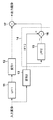
次に、図3〜図7を用いて、本発明の一実施形態例(第1実施形態)を説明する。図3は、本発明の第1実施形態に係る画像処理装置の機能構成を示すブロック図である。図3中、11は入力信号の高周波成分を除去する第1のLPF部であり、12は縮小拡大や幾何変形を行う第1の変形部である。13は縮小拡大や幾何変形を行う第2の変形部である。14は入力信号の低周波成分を除去するHPF部であり、15はHPF部14の一部を構成する第2のLPF部、16はHPF部14の一部を構成する減算器である。17は加算器であり、第2の変形部12において変形された低周波成分画像と、HPF部14において高周波成分が抽出された変形画像とを加算して出力画像を生成する。
(Image processing device)
Next, an embodiment (first embodiment) of the present invention will be described with reference to FIGS. FIG. 3 is a block diagram showing a functional configuration of the image processing apparatus according to the first embodiment of the present invention. In FIG. 3, 11 is a first LPF unit that removes high-frequency components of the input signal, and 12 is a first deformation unit that performs reduction / enlargement and geometric deformation.
図3のように、本実施形態では、入力画像の低周波成分については、第1のLPF部11において低周波成分を抽出してから、第1の変形部12において変形を行う。このため、入力画像の高周波成分が低周波成分に影響することによるモアレの発生を抑制することができる。さらに、入力画像を第2の変形部13において変形を行ってから、第2のHPF部14において高周波成分画像を抽出し、変形済みの低周波成分と、高周波成分とを加算器17において加算する。このように、画像の高周波成分も出力画像に反映されるため、画像のボヤケを抑制することができる。また、変形済みの画像から高周波成分画像を抽出することで、低周波成分に発生したモアレを取り除いてから加算することで、低周波成分に対してモアレを発生させることもない。したがって、モアレ発生の抑止と画像の鮮明さとを両立した画像処理を行うことが可能となる。
As shown in FIG. 3, in the present embodiment, the low frequency component of the input image is deformed by the
HPF部14は単に通常のHPFを用いて構成してもよいが、第2のLPF部15と減算器16の組み合わせて、HPF部14を構成すると、第1のLPF部11の周波数特性を合わせやすい。すなわち、同等の構成のLPFを第1、第2のLPF部11、15に用いることで、第1のLPF部11のカットオフ周波数(第1のカットオフ周波数)とHPF部14のカットオフ周波数(第2のカットオフ周波数)を容易に整合させることができる。このため、加算器17において加算後の画像において、同一周波数成分の重複や特定の周波数のもれを低減することが可能となる。そこで、本実施形態では、第2のLPF部15と減算器16を組み合わせてHPF部14を実現した構成例について説明する。
The
なお、第1のLPF部11および第2のLPF部15は、一般的に使用されている様々なLPFで構成することができる。例えば、平均値フィルター、ガウスフィルター、バタワースフィルター、などである。LPFにおけるカットオフ周波数がサンプリング周波数の4分の1に近いものとして、平均値フィルターであれば、縦×横のサイズが1.25×1.25〜5×5のもの、例えば2×2のサイズのものを用いることができる。なお、小数点を用いたサイズのフィルターは、小数点となる座標位置の定数を小さくすることで実現することができる。同様に、ガウスフィルターであれば、フィルター半径が1.5〜6のもの、例えば、半径が2のサイズのものを用いることができる。また、バタワースフィルターであれば、例えば、カットオフ周波数をサンプリング周波数の4分の1にしたフィルター定数のものを用いることができる。
The
また、第1および第2の変形部12,13は、一般的に使われている様々な補間演算回路で構成可能である。例えば、最近傍補間回路、線形補間回路、キュービック補間回路、などである。第1と第2の変形部12、13は、同じ変形比率で、縮小拡大幾何変形などの変形処理を行う。
Further, the first and
同じ変形比率であれば、第1と第2の変形部の具体的な構成の種類を変えてもよい。例えば、第1の変形部12を最近傍補間回路あるいは線形補間回路とし、第2の変形部13をキュービック補間回路とすることができる。この場合、視認されにくい低周波成分を回路規模の小さな最近傍補間回路や線形補間で実現し、視認されやすい高周波成分を精度の高いキュービック補間回路で行うことになる。このため、小さな回路規模で、視覚特性に応じた画像処理を行うことが可能となる。また、第1の変形部12を最近傍補間回路とし、第2の変形部13を線形補間回路とすることで、回路規模をさらに削減することも可能である。また、第1の変形部12を最近傍補間回路の代わりに、近傍4点の平均値で補間する回路により実現することで、より簡略な回路で構成することも可能である。
If the deformation ratio is the same, the specific configuration types of the first and second deformable portions may be changed. For example, the
なお、第1の変形部12、第2の変形部13において画像の変形を行うと、変形部の入力と出力では画素ごとに処理のタイミングが変わってしまう。このため、第1の変形部12、第2の変形部13内にはバッファメモリを用意する必要があるが、図3では省略している。また、第1、第2のLPF部11、15内にもバッファメモリが必要であるが、これも省略している。
Note that if the image is deformed in the
(画像処理装置の動作)
以下、本実施形態に係る画像処理装置の動作を説明する。入力画像は動画像であり、フレーム内の各画素が順番に本構成ブロックに入力される場合を説明する。入力画像は第1のLPF部11でカットオフ周波数以下の低周波成分のみが抽出され、次に第1の変形部12において、所望の変形率の画像に変形され、第1の変形画像が得られる。
(Operation of image processing device)
Hereinafter, the operation of the image processing apparatus according to the present embodiment will be described. An input image is a moving image, and a case where each pixel in a frame is input to this constituent block in order will be described. From the input image, only the low frequency component equal to or lower than the cut-off frequency is extracted by the
また、入力画像は第2の変形部13にも入力されて、所望の変形率の画像に変形されて、第2の変形画像が得られる。第2の変形画像は、減算器16のプラス側および第2のLPF部15に入力される。第2のLPF部15によって、第2の変形画像の低周波成分が抽出されるので、これを減算器のマイナス側に入力する。減算器16において第2の変形画像からその低周波成分を減算することにより、第2の変形画像の高周波成分のみが得られる。
In addition, the input image is also input to the
このようにして得られた、低周波成分のみの第1の変形画像と第2の変形画像の高周波成分を加算器17で合成することによって、全周波数成分からなる変形画像である出力画像が得られる。
The
ここで、第1のLPF部11と第2のLPF部15は変形率が低い場合には、同じ特性のものを使用しうる。具体的には、0.75倍〜1.25倍程度までは、同じものが使える。縮小率や拡大率、幾何変形率が高い部分においては、第1のLPF部11ないし第2のLPF部15のどちらかのカットオフ周波数ないし、カットオフ周波数に比例するフィルターサイズを調節する必要がある。
Here, when the deformation rate is low, the
(LPFの特性の関係)
次に、第1のLPF部11と第2のLPF部15の特性の関係を、図4を用いて説明する。図4は、本発明の第1実施形態における、元画像に適用する第1のLPF部11と変形画像に適用する第2のLPF部15の特性の関係を示した図である。
(Relationship of LPF characteristics)
Next, the relationship between the characteristics of the
図4(A)(B)(C)(D)は、元画像に適用する第1のLPF部11の特性を一定として、第1の変形部12、第2の変形部13における様々な変形について、第2のLPF部15における特性を変化させる場合を示している。すなわち、図4(A)は、縮小画像に適用する第2のLPF部15の特性を変えた場合を示し、図4(B)は、拡大画像に適用する第2のLPF部15の特性を変えた場合を示している。図4(C)は、幾何変形画像に適用する第2のLPF部15の特性を変えた場合を示し、図4(D)は、変形率の小さい微変形画像に適用する第2のLPF部15の特性を変えた場合を示す。
4A, 4B, 4C, and 4D show various deformations in the
図4(E)(F)(G)(H)は、変形画像に適用する第2のLPF部15の特性を一定として、第1の変形部12、第2の変形部13における様々な変形について、第1のLPF部11における特性を変化させる場合を示している。すなわち、図4(E)は、縮小前に元画像に適用する第1のLPF部11の特性を変えた場合を示し、図4(F)は、拡大前に元画像に適用する第1のLPF部11の特性を変えた場合を示している。図4(G)は、幾何変形前に元画像に適用する第1のLPF部11の特性を変えた場合を示し、図4(H)は、変形率の小さい変形前に元画像に適用する第1のLPF部11の特性を変えた場合を示す。
4E, 4F, 4G, and 4H show various deformations in the
図4中、21は元画像、22は縮小画像、23は拡大画像、24は幾何変形画像、25は変形率の小さい微変形画像、26は標準的なフィルターサイズ、27は変形率だけ小さいフィルターサイズ、28は変形率だけ大きいフィルターサイズを示している。なお、フィルターサイズとは、フィルタリング処理を行う際に、対象画素のまわりの参照する画素の範囲を示すものである。平均値フィルターを例にとると、縦横に3×3〜9×9程度の範囲が通常使われるが、本実施形態においては、変形率に応じて、それよりも大きな範囲のフィルターを使用しうる。
In FIG. 4, 21 is an original image, 22 is a reduced image, 23 is an enlarged image, 24 is a geometrically deformed image, 25 is a slightly deformed image with a small deformation rate, 26 is a standard filter size, and 27 is a filter with a small deformation rate.
平均値フィルターやガウスフィルターでは、フィルターサイズとカットオフ周波数の関係は比例関係にある。そこで、第1、第2のLPF部11、15のフィルターサイズを、第1、第2の変形部12、13における変形率に応じて変えることにより、カットオフ周波数を、画像の変形により変化した空間周波数に合わせることができる。
In the average value filter and the Gaussian filter, the relationship between the filter size and the cutoff frequency is proportional. Therefore, by changing the filter sizes of the first and
図4(A)(B)(C)(D)は、変形前の第1のLPF部11のフィルターサイズを一定とするものである。図4(A)では、縮小画像22に適用する第2のLPF部15のフィルターサイズを、変形率だけ小さなフィルターサイズ27とする。図4(B)では、拡大画像23に適用する第2のLPF部15のフィルターサイズを、変形率だけ大きなフィルターサイズ28とする。図4(C)では、幾何変形画像24に適用する第2のLPF部15のフィルターサイズを、画像内の変形率の高い領域に対して標準より小さなフィルターサイズ27とし、変形率が低い領域に対しては、標準的なフィルターサイズ26とする。図4(D)では、変形率の低い画像25に適用するLPFのフィルターサイズを、標準的なフィルターサイズ26とする。このように、これらの例では、第1、第2の変形部12、13は対象画像に対して所定の同一の変形率で変形を行い、第2のLPF部11のカットオフ周波数は、第1のLPF部15のカットオフ周波数に対して変形率を乗算したものである。
4A, 4B, 4C, and 4D are diagrams in which the filter size of the
図4(E)(F)(G)(H)では、変形後の第2のLPF部15のフィルターサイズを一定とするものである。図4(E)では、元画像21に適用する第1のLPF部11のフィルターサイズを、縮小画像22の変形率の逆数だけ大きなフィルターサイズ28とする。図4(F)では、元画像21に適用する第1のLPF部11のフィルターサイズを、拡大画像23の変形率の逆数だけ小さなフィルターサイズ27とする。図4(G)では、元画像21に適用する第1のLPF部11のフィルターサイズを、幾何変形画像24の領域ごとの変形率に応じてその逆数だけ変化させる。変形率が高い領域のみ、縮小率の逆数だけ標準より大きなフィルターサイズ28とする。図4(H)では、元画像21に適用する第1のLPF部11のフィルターサイズを、変形率が低い微変形画像に応じて、標準的なフィルターサイズ26とする。このように、これらの例では、第1、第2の変形部12、13は対象画像に対して同一の変形率で変形を行い、第1のLPF部15のカットオフ周波数は、第2のLPF部11のカットオフ周波数を変形率を除算したものである。
4 (E), (F), (G), and (H), the filter size of the
上述のように、フィルターサイズを可変とするのは、第1のLPF部11および第2のLPF部15のどちらでも構わないし、或いは、両方のフィルターサイズを可変として、変形前後のカットオフ周波数が一致するようにすればよい。ただ、変形後の画像のカットオフ周波数をSF/4に近づけるとより効果的にモアレを抑制することができるので、変形前の第1のLPF部11のフィルターサイズを可変とするとより効果的である。
As described above, the filter size can be made variable by either the
(フィルターサイズ)
次に、LPFのフィルターサイズを具体的に説明する。変形率によって変えない側のLPFのフィルターサイズは、前述の標準的なフィルターサイズとすることができる。LPFでは、フィルターサイズが大きくなるほどカットオフ周波数が下がり、カットオフ周波数とサンプリング周波数とは比例する関係にある。ナイキスト周波数はSF/2であり、2画素で1周期になる画像成分である。そこで、標準的なフィルターとしては、ナイキスト周波数の半分つまりSF/4をカットオフ周波数とするフィルターである。このようなフィルターは、2画素で1周期になるような周波数成分を完全に無くし、最大4画素で1周期になるような周波数成分を残すフィルターである。
(Filter size)
Next, the filter size of the LPF will be specifically described. The filter size of the LPF on the side that does not change depending on the deformation rate can be the standard filter size described above. In the LPF, the cutoff frequency decreases as the filter size increases, and the cutoff frequency and the sampling frequency are in a proportional relationship. The Nyquist frequency is SF / 2, which is an image component having one cycle for two pixels. Therefore, a standard filter is a filter having a cutoff frequency of half the Nyquist frequency, that is, SF / 4. Such a filter is a filter that completely eliminates a frequency component that makes one cycle for two pixels and leaves a frequency component that makes one cycle for a maximum of four pixels.
平均値フィルターにおいては、2×2のサイズのものでは、2画素の範囲の平均をとるフィルターなので、2画素で1周期になる周波数成分を取ることができるが、4画素で1周期になる成分は取ることができない。 The average value filter is a filter that takes the average of the range of 2 pixels in the 2 × 2 size, so that it is possible to take a frequency component that takes one cycle with two pixels, but a component that takes one cycle with four pixels. Can not take.
そこで、本実施形態では、平均値フィルターの標準的なサイズを2×2とする場合を説明する。そして、標準サイズとするLPFのカットオフ周波数がサンプリング周波数の4分の1から離れるに従って、モアレが残る可能性が出てくるので、カットオフ周波数は、サンプリング周波数(SF)の8分の1から16分の7の間の値の周波数である。その場合のLPFの標準的なフィルターサイズは、平均値フィルターでは1.25×1.25〜5×5の間である。またガウスフィルターでは中央を加重的に平均化するので、平均値フィルターの画素範囲の1.5倍程度である3×3サイズとすることができる。そして、SFの1/8〜7/16の間になるのは、2×2〜7×7の間であり、この範囲にフィルターサイズを設定することができる。そして、変形率によってフィルターサイズを変える側のLPFでは変形率に応じて、平均値フィルターのサイズを変えることになる。 Therefore, in the present embodiment, a case where the standard size of the average value filter is 2 × 2 will be described. Then, as the cutoff frequency of the LPF as the standard size moves away from 1/4 of the sampling frequency, moire may be left, so the cutoff frequency is from 1/8 of the sampling frequency (SF). A frequency with a value between 7/16. The standard filter size of the LPF in that case is between 1.25 × 1.25 and 5 × 5 for the average value filter. In addition, since the center is weighted in the Gaussian filter, it can be a 3 × 3 size that is about 1.5 times the pixel range of the average value filter. And between 1/8 and 7/16 of SF is between 2 × 2 and 7 × 7, and the filter size can be set within this range. In the LPF that changes the filter size according to the deformation rate, the size of the average value filter is changed according to the deformation rate.
標準的なフィルターサイズに対応して変形率によって変更するフィルターサイズを、具体的に説明する。例えば、図4(B)において、拡大率が1.8倍の場合で、拡大前の第1のLPF部11の平均値フィルターを標準的なサイズの中心値である2×2とする場合を説明する。第2のLPF部15のサイズ=第1のLPF部11のサイズ×変形率=2×1.8=3.6であるので、拡大後の第2のLPF部15の平均値フィルターのサイズは3×3にすればよい。
The filter size that changes according to the deformation rate in correspondence with the standard filter size will be specifically described. For example, in FIG. 4B, when the enlargement ratio is 1.8 times, the average value filter of the
また、例えば、図4(E)において、縮小率が0.7倍の場合で、縮小後の第2のLPF部15の平均値フィルターを標準的なサイズの中心値である2×2とする場合を説明する。第1のLPF部11のサイズ=第2のLPF部15のサイズ/変形率=2/0.7≒3であるので、縮小前の第1のLPF部11の平均値フィルターを3×3とすればよい。最適値がない場合も近い値にすれば、出力画像の周波数分布の劣化を極力防ぐことができる。
Further, for example, in FIG. 4E, when the reduction ratio is 0.7 times, the average value filter of the
(フィルターの構成例)
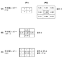
以下、図5〜図7を用いて、各サイズのLPFあるいはHPFの具体例を説明する。図5は、平均値フィルターで実現したLPFの構成例を示す図である。図5において、格子全体の中心のハッチングが施された格子は対象画素を示し、各格子内の数字は対象画素および周辺に位置する画素に対する倍率を示している。
(Filter configuration example)
Hereinafter, specific examples of LPFs or HPFs of each size will be described with reference to FIGS. FIG. 5 is a diagram illustrating a configuration example of an LPF realized by an average value filter. In FIG. 5, a lattice with hatching at the center of the entire lattice indicates a target pixel, and a number in each lattice indicates a magnification with respect to the target pixel and surrounding pixels.
LPFは、画素値に図に示す倍率を乗算したもの合計値を倍率の合計値で割り算することによって、出力を得る。あるいは割り算の代わりに、近似的に乗算とシフト演算によって演算することにより、出力を得る。 The LPF obtains an output by dividing a total value obtained by multiplying the pixel value by the magnification shown in the figure by the total value of the magnification. Alternatively, instead of division, an output is obtained by approximately calculating by multiplication and shift calculation.
図5(A)は、2×2サイズの平均値フィルターおよび3x3サイズの平均値フィルターに置き換えたものを示す。(A1)は2×2の座標を用いたものであるが画素の重心がずれてしまうので、代わりに(A2)として重心位置をずらして3×3で表した等価なフィルターを用いる。各画素用の倍率0.25〜1を対応する画素の画素値に乗算したものの合計値を、倍率の合計値である4で除算することにより、対象画素のフィルタリング出力が演算される。上述したように、このサイズの平均値フィルターは、カットオフ周波数がSF/4に近いので標準的なサイズのLPFとなる。 FIG. 5A shows a 2 × 2 size average value filter and a 3 × 3 size average value filter. (A1) uses 2 × 2 coordinates, but the center of gravity of the pixel is shifted. Instead, an equivalent filter represented by 3 × 3 is used by shifting the position of the center of gravity as (A2). The filtered output of the target pixel is calculated by dividing the total value obtained by multiplying the pixel value of the corresponding pixel by the magnification 0.25 to 1 for each pixel by 4 that is the total value of the magnification. As described above, the average value filter of this size is a standard size LPF because the cutoff frequency is close to SF / 4.
図5(B)は、1.5×1.5サイズの平均値フィルターとして3×3の座標の定数で実現したものを示す。各画素用の倍率1を対応する画素の画素値に乗算したものの合計値を、倍率の合計値である2で除算することにより、対象画素のフィルタリング出力が演算される。このサイズの平均値フィルターは、標準的なサイズより小さなサイズのLPFであり、カットオフ周波数がSF/4よりも高くなる。
FIG. 5B shows a 1.5 × 1.5 size average value filter realized with a constant of 3 × 3 coordinates. The filtered output of the target pixel is calculated by dividing the total value obtained by multiplying the pixel value of the corresponding pixel by the
図5(C)は、3×3サイズの平均値フィルターを示す。各画素用の倍率1を対応する画素の画素値に乗算したものの合計値を、倍率の合計値である9(図5(B)の例では、倍率1が、9個設定されている)で除算することにより、対象画素のフィルタリング出力が演算される。近似値を算出する場合は、対象画素の画素値に7を乗算して64で除算する(6ビット切り捨てる)ことによりフィルタリング出力が演算される。このサイズの平均値フィルターは、標準的なサイズより大きなサイズのLPFであり、カットオフ周波数がSF/4よりも低くなる。
FIG. 5C shows an average value filter of 3 × 3 size. The total value obtained by multiplying the pixel value of the corresponding pixel by the
次に、図6は、ガウスフィルターで実現したLPFの構成例を示す図である。図6(A)は、3×3サイズ(半径2)のガウスフィルターを示す。各画素用の倍率を対応する画素の画素値に乗算したものの合計値を16で除算する(4ビット切り捨てる)ことにより、対象画素のフィルタリング出力が演算される。上述したように、このサイズの平均値フィルターは、カットオフ周波数がSF/4に近いので標準的なサイズのLPFとなる。 Next, FIG. 6 is a diagram illustrating a configuration example of an LPF realized by a Gaussian filter. FIG. 6A shows a Gaussian filter of 3 × 3 size (radius 2). The filtered output of the target pixel is calculated by dividing the sum of the pixel value of the corresponding pixel multiplied by the pixel value for each pixel by 16 (4 bits are discarded). As described above, the average value filter of this size is a standard size LPF because the cutoff frequency is close to SF / 4.
図6(B)は、3×3サイズ(半径1.5)のガウスフィルターを示す。各画素用の倍率を対応する画素の画素値に乗算したものの合計値を8で除算する(3ビット切り捨てる)ことにより、対象画素のフィルタリング出力が演算される。このサイズのガウスフィルターは、カットオフ周波数がSF/4に近いが若干高いので、標準的なサイズあるいは標準的なサイズより小さなサイズのLPFとして使用する。 FIG. 6B shows a 3 × 3 size (radius 1.5) Gaussian filter. The filtered output of the target pixel is calculated by dividing the sum of the pixel values of each pixel multiplied by the pixel value of the corresponding pixel by 8 (3 bits are discarded). A Gaussian filter of this size has a cutoff frequency close to SF / 4, but is slightly higher, so it is used as an LPF having a standard size or a size smaller than the standard size.
図6(C)は、5×5サイズ(半径6)のガウスフィルターを示す。各画素用の倍率を対応する画素の画素値に乗算したものの合計値を256で除算する(8ビット切り捨てる)ことにより、対象画素のフィルタリング出力が演算される。このサイズのガウスフィルターは、カットオフ周波数がSF/4に近いが若干低いので、標準的なサイズあるいは標準的なサイズより大きなサイズのLPFとして使用する。 FIG. 6C shows a 5 × 5 size (radius 6) Gaussian filter. The filtered output of the target pixel is calculated by dividing the total value obtained by multiplying the pixel value of the corresponding pixel by the magnification for each pixel by 256 (rounding down 8 bits). A Gaussian filter of this size has a cutoff frequency close to SF / 4 but is slightly lower, so it is used as an LPF having a standard size or a size larger than the standard size.
図7は、HPFの構成例を示す図である。図3において、第2のLPF部15と減算器16を組み合わせずに、専用のHPFを設けて一度に演算する場合に、ここに説明するHPFが使用される。
FIG. 7 is a diagram illustrating a configuration example of the HPF. In FIG. 3, the HPF described here is used when a dedicated HPF is provided and calculation is performed at once without combining the
図7(A)は、2×2サイズのHPFを3×3サイズに置き直したHPFを示す。各画素用の倍率を対応する画素の画素値に乗算したものの合計値を、正または負の倍率の合計値である3で除算することにより、対象画素のフィルタリング出力が演算される。近似値を算出する場合は、対象画素の画素値に85を乗算して256で除算する(8ビット切り捨てる)ことによりフィルタリング出力が演算される。上述したように、このサイズのHPFは、カットオフ周波数がSF/4に近いので標準的なサイズのHPFとなる。 FIG. 7A shows an HPF in which a 2 × 2 size HPF is replaced with a 3 × 3 size. The filtered value of the target pixel is calculated by dividing the total value of the pixel values of the corresponding pixel multiplied by the pixel value of each pixel by 3 that is the total value of the positive or negative magnification. When calculating the approximate value, the filtering output is calculated by multiplying the pixel value of the target pixel by 85 and dividing by 256 (rounded down to 8 bits). As described above, this size HPF is a standard size HPF because the cutoff frequency is close to SF / 4.
図7(B)は、1.5×1.5サイズのHPFを3×3サイズの定数で実現したHPFを示す。各画素用の倍率を対応する画素の画素値に乗算したものの合計値を計算することにより、対象画素のフィルタリング出力が演算される。このサイズの平均値フィルターは、標準的なサイズより小さなサイズのHPFであり、カットオフ周波数がSF/4よりも高くなる。 FIG. 7B shows an HPF in which a 1.5 × 1.5 size HPF is realized with a 3 × 3 size constant. A filtering output of the target pixel is calculated by calculating a total value obtained by multiplying the pixel value of the corresponding pixel by the magnification for each pixel. The average value filter of this size is an HPF having a size smaller than the standard size, and has a cutoff frequency higher than SF / 4.
図7(C)は、3×3サイズのHPFを示す。各画素用の倍率を対応する画素の画素値に乗算したものの合計値を、正または負の倍率の合計値である8で除算する(3ビット切り捨てる)ことにより、対象画素のフィルタリング出力が演算される。このサイズの平均値フィルターは、標準的なサイズより大きなサイズのHPFであり、カットオフ周波数がSF/4よりも低くなる。 FIG. 7C shows a 3 × 3 HPF. The filtered output of the target pixel is calculated by dividing the total value obtained by multiplying the pixel value of the corresponding pixel by the magnification for each pixel by 8 which is the total value of the positive or negative magnification (3 bits are rounded down). The The average value filter of this size is an HPF having a size larger than the standard size, and the cut-off frequency is lower than SF / 4.
上記のように、本実施形態では、モアレの発生原理に着目して、入力画像の低周波成分についてはLPFを経由してから画像の変形を行い、高周波成分については画像の変形を行ってからHPFを経由して、両者を合成する。このように、高周波成分と低周波成分を別に処理することにより、画像の変形におけるサンプリング周波数と高周波成分の干渉等に起因するモアレの発生を抑制すると共に、高周波成分を出力画像に反映させることで画像のボヤケを抑制することが可能となる。 As described above, in this embodiment, paying attention to the generation principle of moire, the low-frequency component of the input image undergoes image deformation after passing through the LPF, and the high-frequency component undergoes image deformation. Both are synthesized via HPF. In this way, by separately processing the high-frequency component and the low-frequency component, it is possible to suppress the generation of moire caused by the interference between the sampling frequency and the high-frequency component in the deformation of the image and to reflect the high-frequency component in the output image. Image blur can be suppressed.
第1実施形態において、変形後の高周波成分を求める構成は、通常のHPFでもよいが、LPFと減算器を組み合わせたものでもよいことなどを説明した。このように、本発明は上記実施形態の具体的構成に限ることはなく、発明の趣旨を同じとする別の構成によっても実施することができる。 In the first embodiment, the configuration for obtaining the high-frequency component after deformation may be a normal HPF, but it may be a combination of an LPF and a subtractor. Thus, the present invention is not limited to the specific configuration of the above-described embodiment, and can be implemented by another configuration having the same gist of the invention.
<<第2実施形態>>
第1実施形態の画像処理装置は、入力画像と出力画像の画素の階調値が、ガンマ系でもリニア系でも適用することができる。もっとも、階調値がガンマ系で表される場合とリニア系で表される場合とでは、その特性により、回路規模や変形処理に対する反応が異なる。すなわち、階調値がガンマ系である場合には、階調ビット数が8〜10ビットあればよいので、LPFや変形処理回路が小さくできる。階調値がリニア系である場合には、階調ビット数が12〜16ビット必要となり処理回路が大きくなる。一方、リニア系における変形処理の補間値は正確であるが、ガンマ系の変形処理においては線形補間やキュービック補間で求めた値が正確でなくなるので、出力画像にモアレではないがモアレに似た妨害(ノイズ)が現れることがある。そこで本実施形態(第2実施形態)では、ガンマ系処理とリニア系処理の長所を組み合わせて、比較的小さな処理回路で正確な出力画像を得られる構成を説明する。
<< Second Embodiment >>
The image processing apparatus according to the first embodiment can be applied regardless of whether the gradation value of the pixels of the input image and the output image is a gamma system or a linear system. However, the response to the circuit scale and the deformation process differs depending on the characteristics of the case where the gradation value is expressed in the gamma system and the case where the gradation value is expressed in the linear system. That is, when the gradation value is a gamma system, the number of gradation bits only needs to be 8 to 10, so that the LPF and the deformation processing circuit can be reduced. When the gradation value is a linear system, the number of gradation bits is 12 to 16 bits, and the processing circuit becomes large. On the other hand, the interpolation value of the transformation process in the linear system is accurate, but the value obtained by the linear interpolation or cubic interpolation is not accurate in the transformation process of the gamma system, so the output image is not moire but interference similar to moire. (Noise) may appear. Therefore, in this embodiment (second embodiment), a configuration in which an accurate output image can be obtained with a relatively small processing circuit by combining the advantages of gamma processing and linear processing will be described.
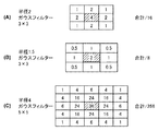
図8は、本発明の第2施形態に係る画像処理装置の構成を示すブロック図である。図8中、11〜17の構成要素は、図3の構成要素と同様であり、詳細な説明は省略する。51はガンマ系階調値をリニア系階調値に変換するガンマ2.2処理部、52は21はリニア系階調値をガンマ系階調値に変換するガンマ0.45処理部である。
FIG. 8 is a block diagram showing the configuration of the image processing apparatus according to the second embodiment of the present invention. In FIG. 8, the
ガンマ2.2処理部51は入力値を2.2乗に演算する回路であり、ガンマ0.45処理部52は入力値を0.45乗に演算する回路である。ガンマ2.2処理部51およびガンマ0.45処理部52は、例えば、ルックアップテーブルによって構成することができる。あるいは、入力値を2乗あるいは0.5乗とする乗算器および平方根演算器を用いて、簡易に構成することもできる。
The gamma 2.2
第2実施形態では、入力画像としてガンマ系の階調値が入ってくる場合を想定している。第1のLPF部11、第1の変形部12、第2のLPF部15、減算器16、加算器17はガンマ系のまま処理を行う。第2の変形部13はリニア系の処理を行う。ガンマ系の入力画像を、ガンマ2.2処理部51でリニア系に直してから、第2の変形部13で縮小拡大幾何変形などの変形処理を行い、第2の変形画像(リニア系)を得る。第2の変形画像(リニア系)をガンマ0.45処理部52でガンマ系に直してから、第2のLPF部15および加算器17に供給する。
In the second embodiment, it is assumed that a gamma gradation value is input as an input image. The
上記のように、本実施形態では、入力画像の高周波成分についての変形を行う際は、ガンマ系階調値として表された入力画像をリニア系階調値に変換してから変形処理を行い、この変形された入力画像をガンマ系階調値に変換して、HPFの処理を行う。このため、リニア系で処理する回路を第2の変形部13のみとできるので、全処理回路をリニア系とするより、処理回路が少なくて済む。また、正確な補間値を用いて、第2の変形画像を作成するので、その高周波成分も正確な値となり、モアレに似た妨害が発生することもない。
As described above, in the present embodiment, when the high-frequency component of the input image is deformed, the input image represented as the gamma system gradation value is converted into the linear system gradation value, and then the deformation process is performed. The deformed input image is converted into a gamma gradation value, and HPF processing is performed. For this reason, since the circuit to be processed in the linear system can be only the
なお本実施形態では、減算器16と加算器17の処理順番が図3と逆になっているが、この順番であれば、減算器16による演算が本構成による最後の処理になるので、加算器17で負の値を計算処理する必要がなくなり、処理回路が簡便で済む利点がある。
In this embodiment, the processing order of the
<<第3実施形態>>
次に、本発明の第3実施形態として、第1の変形画像と第2の変形画像の使用割合を調整する画像処理装置の構成について説明する。図9は、各変形画像の比率を変えて合成する画像処理装置の構成を示すブロック図である。図9中、11〜17の構成要素は図3の構成要素と同様であり、詳細な説明は省略する。61は低周波成分を変形した第1の変形画像に対する乗算器、62は第2の変形画像に対する乗算器、63は第2の変形画像の低周波成分に対する乗算器である。
<< Third Embodiment >>
Next, as a third embodiment of the present invention, the configuration of an image processing apparatus that adjusts the usage ratio of the first modified image and the second modified image will be described. FIG. 9 is a block diagram illustrating a configuration of an image processing apparatus that synthesizes the images by changing the ratio of the deformed images. In FIG. 9, the
61〜63の各乗算器には、それぞれに対して別の値の定数を乗算することができる。乗算器61〜63において乗算する定数をそれぞれa,b,cとし、本実施形態では定数a,b,cはいずれも0.5〜2.0の範囲内にある値である。
Each of the
入力画像は、第1のLPF部11によって低周波成分のみが抽出されてから、第1の変形部12によって変形されて第1の変形画像となる。乗算器61は、この第1の変形画像に対してa倍の乗算を行う。乗算器62は、第2の変形部13によって変形された入力画像(第2の変形画像)に対して、b倍の乗算を行う。乗算器63は、第2の変形部13によって変形された第2の変形画像から第2のLPF部15により低周波成分のみを抽出した画像に対して、c倍の乗算を行う。乗算器61の出力と乗算器62の出力を加算器17で加算したものに、乗算器63の出力を減算器16で減算することにより、出力画像を得る。なお、乗算器61〜63は対象画像の階調値に対して定数を乗じる演算を行う。
Only the low-frequency component is extracted from the input image by the
本実施形態においては、画像処理の途中で3種類の画像の比率を変えることができるので、出力画像に対して様々な調整や効果を加えることができる。例えば、第2の変形部13において拡大や幾何変形などの変形処理を行うと、一般的にシャープネスが不足した画像になることが多い。そこで、各定数を、例えば、a=1.0,b=c=1.2とすることにより、画像における高周波成分の比率を低周波成分に比べて増やすことができるので、出力画像としてシャープな変形画像を得ることができる。
In the present embodiment, since the ratio of the three types of images can be changed during the image processing, various adjustments and effects can be added to the output image. For example, when a deformation process such as enlargement or geometric deformation is performed in the
また、実施形態1の構成においてLPFのカットオフ特性がなだらかであるなどの原因により、モアレが若干残ってしまう場合に、本実施形態の処理で対応することが可能である。モアレを抑制する効果を高めるために、第2の変形後に画像の低周波成分を大きくし、その分だけ、低周波成分の第1の変形画像を大きくすると、減算器16でモアレの原因となる成分をより大きく減算することになる。例えば、各乗算器の定数をa=1.1,b=1.0,c=1.1とすることにより、このようなモアレの抑制を実現できる。
Further, in the configuration of the first embodiment, when the moiré is left slightly due to the reason that the cutoff characteristic of the LPF is gentle, it is possible to cope with the processing of the present embodiment. In order to increase the effect of suppressing moire, if the low frequency component of the image is increased after the second deformation and the first modified image of the low frequency component is increased by that amount, moire is caused in the
なお、図9の構成例では、乗算器61の出力と乗算器62の出力とを加算器17において加算したものから、減算器16において、乗算器63の出力を減算しているが、回路構成はこれに限られない。例えば、図3の構成例と同様に、入力画像の高周波成分について乗算器62の出力から乗算器63の出力を減算し、この減算結果に低周波成分についての乗算器61の出力を加算するようにしてもよい。
In the configuration example of FIG. 9, the output of the
<<第4実施形態>>
次に、入力画像が静止画である場合や、入力画像のフレームレートが、変形処理回路で処理可能なフレームレートの半分以下である場合に、実施可能な形態を第4実施形態として説明する。図10は、第4実施形態における、入力画像が静止画またはフレームレートが遅い場合の画像処理装置の構成を示すブロック図である。
<< Fourth Embodiment >>
Next, an embodiment that can be implemented when the input image is a still image or when the frame rate of the input image is half or less of the frame rate that can be processed by the deformation processing circuit will be described as a fourth embodiment. FIG. 10 is a block diagram illustrating a configuration of an image processing apparatus when an input image is a still image or a frame rate is low in the fourth embodiment.
図10中、11〜17の構成要素は図3の構成要素と同様であり、詳細な説明は省略する。71は入力画像を一時記憶する第1のフレームバッファ、72は変形画像を一時記憶する第2のフレームバッファ、73は拡大縮小幾何変形などを行う変形部である。
In FIG. 10, the
このような構成による画像処理装置の動作を説明する。入力画像は、第1のLPF部11に入力されるとともに、第1のフレームバッファ71に一時記憶・保持される。第1のLPF部11の出力は変形部73によって変形されて第1の変形画像となり、第2のフレームバッファ72に一時記憶・保持される。
The operation of the image processing apparatus having such a configuration will be described. The input image is input to the
その動作が終わった後に、第1のフレームバッファ71から入力画像が読み出され、変形部73に入力される。変形部73で変形された第2の変形画像は、加算器17および第2のLPF部15に入力される。第2のフレームバッファから第1の変形画像が読み出され、加算器17によって第2の変形画像と加算される。その出力から、減算器16によって、第2のLPF部15の出力が減算され、出力画像を得る。
After the operation is completed, the input image is read from the
本実施形態においては、回路規模の大きい変形部は1構成だけあればよいので、回路規模を小さくすることが可能となる。 In the present embodiment, only one configuration is required for the deformed portion having a large circuit scale, so that the circuit scale can be reduced.
<<第5実施形態>>
第1〜第4の実施形態では、画像処理装置の各構成要素を専用のハードウェアにより構成する例を説明したが、汎用の情報処理装置を用いても同様の処理を行うことができる。本実施形態では、汎用の情報処理装置による構成例として、マイクロプロセッサなどを用いた構成によって、変形等の画像処理を行う場合を、図11、図12を用いて説明する。
<< Fifth Embodiment >>
In the first to fourth embodiments, an example in which each component of the image processing apparatus is configured by dedicated hardware has been described. However, similar processing can be performed using a general-purpose information processing apparatus. In the present embodiment, as a configuration example of a general-purpose information processing device, a case where image processing such as deformation is performed by a configuration using a microprocessor or the like will be described with reference to FIGS.
図11は、第5実施形態における、マイクロプロセッサを用いた構成によるブロック図である。図11中、81は演算および制御を行うマイクロプロセッサ(MPU)、82は入力インターフェース、83は出力インターフェースである。84はコンピュータプログラムを格納するROM(読出し専用メモリ)、85はワーキングメモリとして使用するRAM(書込み可能メモリ)、86は画像の一時記憶を行うストレージ、である。なお、RAM85が複数枚の画像を記憶できるほど大きなものである場合は、ストレージ86はなくても構わない。図11の構成を有する汎用の情報処理装置として、組込み装置、パーソナルコンピュータ(PC)、タブレット端末、スマートフォン、クラウドサーバー等の装置を用いることが可能である。
FIG. 11 is a block diagram showing a configuration using a microprocessor in the fifth embodiment. In FIG. 11, 81 is a microprocessor (MPU) that performs calculation and control, 82 is an input interface, and 83 is an output interface.
図12は、第5実施形態における、マイクロプロセッサによって行う処理を示したフローチャートである。図11の構成において、MPU81が、ROM84やストレージ86等に書き込まれたコンピュータプログラムに従い、図12のフローチャートに示した各ステップの処理を実行する。以下、処理のステップごとに説明する。
FIG. 12 is a flowchart showing processing performed by the microprocessor in the fifth embodiment. In the configuration of FIG. 11, the
まず、ステップ901において、入力画像を入力インターフェース82よりRAM85に読み込む。ステップ902において、読み込んだ入力画像を、ストレージ86にも一時記憶する。ステップ903において、RAM85上の入力画像に対し、LPF処理を行い、LPF画像1としてRAM85上に一時記憶する。このLPF処理は、第1実施形態で説明した第1のLPF部11の処理と同様の処理である。
First, in step 901, the input image is read from the
ステップ904において、そのLPF画像1に対し、拡大縮小幾何変形などの変形処理を行い第1の変形画像を得る。ステップ905において、第1の変形画像をストレージ86に一時記憶する。ステップ906において、ストレージ86から入力画像を読み出し、拡大縮小幾何変形などの変形処理を行い第2の変形画像を得て、RAM85上に一時記憶する。ステップ907において、第2の変形画像をストレージ86に一時記憶する。
In
ステップ908において、RAM85上の第2の変形画像に対し、LPF処理を行い、LPF画像2を得る。このLPF処理は、第1実施形態で説明した第2のLPF部15の処理と同様の処理である。ステップ909において、LPF画像2をストレージ86に一時記憶する。
In
ステップ910において、第1の変形画像と第2の変形画像をストレージ86から読み出して、加算を行い、加算画像を得る。ステップ911において、その加算画像から、ストレージ86から読み出したLPF画像2を減算して、処理結果を得る。処理結果をステップ912で一時記憶する。一時記憶した処理結果を、ステップ913において、出力インターフェース83を通じて出力画像として出力する。
In
以上の動作によって、第1実施形態と同様の処理をマイクロプロセッサによって行う工程を説明した。同様にマイクロプロセッサを用いて、第2実施形態ならびに第3実施形態の処理を行えることは自明であるため、説明を省略する。本実施形態のように、汎用の情報処理装置において前述の実施形態に係る画像処理装置と同様の動作を行うことで、モアレとボヤケの両方を抑制しつつ画像処理を行うことが可能となる。 The process of performing the same processing as in the first embodiment by the microprocessor by the above operation has been described. Similarly, since it is obvious that the processing of the second embodiment and the third embodiment can be performed using a microprocessor, the description thereof is omitted. By performing the same operation as the image processing apparatus according to the above-described embodiment in a general-purpose information processing apparatus as in the present embodiment, it is possible to perform image processing while suppressing both moire and blur.
上記実施形態における画像の拡大縮小幾何変形の別の例として、輝度色差信号における色差成分の間引き処理が行われても良い。 As another example of the enlargement / reduction geometric deformation of the image in the above embodiment, the thinning process of the color difference component in the luminance color difference signal may be performed.
一般的に、輝度色差信号YPbPrの画素数比率が同じものである4:4:4信号から、水平方向の色差信号を半分に間引いた4:2:2信号や、水平および垂直方向の色差信号を半分に間引いて4分の1とした4:2:0信号を作成している。この時に行なう間引き処理はLPFを使った縮小処理であるので、上記実施形態の動作に適用することができる。適用する場合には、4:4:4信号における輝度信号Yに対しては上記の画像処理を行なわず、色差信号PbおよびPrについて上記の画像処理を行なった後、元のままの輝度信号Yと座標位置を合わせる。これにより、色差信号のモアレとボヤケの両方を抑制した4:2:2信号や4:2:0信号を得ることができる。 Generally, a 4: 2: 2 signal obtained by thinning a horizontal color difference signal in half from a 4: 4: 4 signal having the same pixel number ratio of the luminance color difference signal YPbPr, or a horizontal and vertical color difference signal. Is halved to create a 4: 2: 0 signal that is a quarter. Since the thinning process performed at this time is a reduction process using an LPF, it can be applied to the operation of the above embodiment. When applied, the luminance signal Y in the 4: 4: 4 signal is not subjected to the above-described image processing, and after performing the above-described image processing on the color difference signals Pb and Pr, the original luminance signal Y And the coordinate position. Thereby, it is possible to obtain a 4: 2: 2 signal or a 4: 2: 0 signal in which both moire and blur of the color difference signal are suppressed.
<<第6実施形態>>
上記実施形態においては、主に画像の拡大縮小幾何変形をする場合について述べてきた。本発明の第6の実施形態(第6実施形態)では、スクリーン印刷におけるAMスクリーン(網点)の作成において、画像をスクリーン線数に合わせて縮小拡大する場合の処理について説明する。
<< Sixth Embodiment >>
In the above-described embodiment, the case where the image is subjected to enlargement / reduction geometric deformation has been mainly described. In the sixth embodiment (sixth embodiment) of the present invention, processing in the case of creating an AM screen (halftone dot) in screen printing and reducing or enlarging the image in accordance with the number of screen lines will be described.
図13は、AMスクリーニング処理を説明する図であり、図13(A)は入力画像、図13(B)はスクリーン画像、を表す。 13A and 13B are diagrams for explaining the AM screening process. FIG. 13A shows an input image, and FIG. 13B shows a screen image.
図13(A)中、151は入力画像の一部、152は入力画像中の一つの画素、153はAMスクリーンにおけるスクリーン線、である。図13(B)において、154はスクリーン線の1つの交点におけるインク量、155はインク量を決定する画素範囲、である。 In FIG. 13A, 151 is a part of the input image, 152 is one pixel in the input image, and 153 is a screen line on the AM screen. In FIG. 13B, 154 is an ink amount at one intersection of screen lines, and 155 is a pixel range for determining the ink amount.
AM(Amplitude Modulated)スクリーニング処理とは、スクリーン線153の交点ごとに印刷するべきインク量154を演算する処理である。図13では、入力画像の12×12の画素から、スクリーン画像における5×5のスクリーン線に変換する処理を示しており、入力画像151の解像度からスクリーン線153の解像度に変換する縮小変形の演算処理となる。なお、スクリーン線153は、インクの各色ごとに斜めに配置することが一般的であるので、その場合のスクリーニング処理は、縮小処理に加えて幾何変形処理になる。
The AM (Amplitude Modulated) screening process is a process for calculating an
図14は、本発明の第6実施形態に係る画像処理装置の構成を示すブロック図である。図14中、11、14〜17の構成要素は、第1実施形態で説明した図3の構成要素と同様であり、詳細な説明は省略する。131は低周波画像のAMスクリーン画像を作る第1のAMスクリーニング処理部であり、132は入力画像のAMスクリーン画像を作る第2のAMスクリーニング処理部である。
FIG. 14 is a block diagram showing a configuration of an image processing apparatus according to the sixth embodiment of the present invention. In FIG. 14, the
入力画像は、第1のLPF部11によって低周波成分のみが抽出されてから、第1のAMスクリーニング処理部131によって所望の線数に合わせたAMスクリーンが生成されて、第1のAMスクリーン画像となる。
From the input image, only the low frequency component is extracted by the
また、入力画像は第2のAMスクリーニング処理部132にも入力されて、所望の線数である第2のAMスクリーン画像が得られる。第2の第2のAMスクリーン画像は、減算器16のプラス側および第2のLPF部15に入力される。第2のLPF部15によって、第2のAMスクリーン画像の低周波成分が抽出されるので、これを減算器のマイナス側に入力する。減算器16において第2のAMスクリーン画像からその低周波成分を減算することにより、第2のAMスクリーン画像の高周波成分のみが得られる。
The input image is also input to the second
このようにして得られた、低周波成分のみの第1のAMスクリーン画像と第2のAMスクリーン画像の高周波成分を加算器17で合成することによって、全周波数成分からなるAMスクリーン画像である出力画像が得られる。以上のように、本実施形態においては、入力画像の低周波成分についてはLPFを経由してからAMスクリーン処理を行い、高周波成分についてはAMスクリーン処理を行ってからHPFを経由して、両者を合成する。このように、AMスクリーン処理を行う場合であっても、高周波成分と低周波成分を別に処理することにより、第1実施形態と同様に、モアレの発生を抑制すると共に画像のボヤケを抑制することが可能となる。
The
<<第7実施形態>>
上記実施形態においては、拡大縮小変形における変形率が任意のものに対応できる場合を述べてきた。本発明の第7の実施形態(第7実施形態)では、3板式プロジェクターの各素子の微妙なずれを補正するレジストレーション補正処理など、変形率がごく小さい変形処理に、上記手法を適用する場合を説明する。
<< Seventh Embodiment >>
In the above-described embodiment, a case has been described in which the deformation rate in the enlargement / reduction deformation can correspond to an arbitrary one. In the seventh embodiment (seventh embodiment) of the present invention, the above method is applied to a deformation process with a very small deformation rate, such as a registration correction process for correcting a subtle displacement of each element of a three-plate projector. Will be explained.
図15は、レジストレーションずれを説明する図である。図15中、点線で表した161はR色(赤色)の投影画像(放射画像)、実線で表した162はG色(緑色)の投影画像、一点鎖線で表した163はB色(青色)の投影画像、である。 FIG. 15 is a diagram for explaining registration deviation. In FIG. 15, 161 indicated by a dotted line is an R color (red) projection image (radiation image), 162 indicated by a solid line is a G color (green) projection image, and 163 indicated by an alternate long and short dash line is B color (blue). Projection image.
3板式のプロジェクターでは、ランプ光をRGB色に分けて、各色ごとに液晶またはデジタルミラーデバイスなどの光学変調素子で入力画像に応じて変調して、変調後の3色を光学系で統合し、統合した変調光を投影レンズによってスクリーンに投影する。この時に、変調素子の位置と統合する光学系の間に設計値からのわずかなずれがあると、各色の投影光がぴったり重ならずに、ずれて投影されてしまう。そこで変調位置の位置と光学系を微調整することで、投影画像のずれ量を通常1画素以下に抑えることができる。しかしながら、図15に示すように、G色の放射画像162に対し、R色の放射画像161やB色の放射画像163の位置が、1画素以下のずれ量で投影されることになる。この時、投影した画像には色ずれと呼ばれる妨害が発生してしまう。色ずれとは、単色の線の縁にR色やB色の色が表示されてしまうことにより、単色なのに色が見えてしまう妨害である。
In a three-plate projector, the lamp light is divided into RGB colors, and each color is modulated according to an input image by an optical modulation element such as a liquid crystal or a digital mirror device, and the three colors after modulation are integrated by an optical system, The integrated modulated light is projected onto the screen by the projection lens. At this time, if there is a slight deviation from the design value between the position of the modulation element and the optical system to be integrated, the projection light of each color is projected without being exactly overlapped. Therefore, by finely adjusting the position of the modulation position and the optical system, the amount of deviation of the projected image can be normally suppressed to 1 pixel or less. However, as shown in FIG. 15, the positions of the R-
この色ずれ妨害を軽減するために、レジストレーション補正と呼ばれる処理が一般に行われている。レジストレーション補正とは、R色とB色の入力画像に幾何変形処理を行い、R色の投影画像161およびB色の投影画像163を、G色の投影画像162に一致させるものである。なお、レジストレーション処理を行っても投影された各色の画素が完全に一致するわけではないので、わずかな色ずれが残るが、視聴者に認識できない程度まで軽減させることが可能である。
In order to reduce the color misregistration interference, a process called registration correction is generally performed. The registration correction is to perform geometric deformation processing on the input images of R and B colors so that the projected
図16は、本発明の第7施形態に係る画像処理装置の構成を示すブロック図である。図16中、11、14〜17の構成要素は、第1実施形態で説明した図3の構成要素と同様であり、詳細な説明は省略する。141は入力画像のレジストレーション補正処理部である。
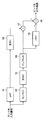
FIG. 16 is a block diagram showing a configuration of an image processing apparatus according to the seventh embodiment of the present invention. In FIG. 16, the
本構成において入力画像は、第1のLPF部11による低周波成分画像には、変形処理であるレジストレーション補正を行わない。これは、レジストレーション補正処理における変形処理が数画素以下であり、そのほとんどは1画素程度の変形処理であるので、低周波画像に対してレジストレーション補正を行っても、画像の変化は少ないからである。
In this configuration, the input image is not subjected to registration correction, which is a deformation process, for the low-frequency component image by the
他方、入力画像はレジストレーション補正処理部141にも入力されて、所望のレジストレーション補正を行ったレジストレーション補正画像が得られる。レジストレーション補正画像は、減算器16のプラス側および第2のLPF部15に入力される。第2のLPF部15によって、レジストレーション補正画像の低周波成分が抽出されるので、これを減算器のマイナス側に入力する。減算器16においてレジストレーション補正画像からその低周波成分を減算することにより、レジストレーション補正画像の高周波成分のみが得られる。
On the other hand, the input image is also input to the registration
このようにして得られた、低周波成分のみの画像とレジストレーション補正画像の高周波成分を加算器17で合成することによって、全周波数成分からなるレジストレーション補正画像である出力画像が得られる。
By combining the image of only the low frequency component and the high frequency component of the registration correction image obtained in this way by the
本実施形態においては、第1実施形態と同様に、モアレの抑制とボヤケの抑制を両立することに加えて、レジストレーション補正処理を1回しか行わないので、処理回路がコンパクトになる。プログラムで行う場合は、高速に処理できるという利点がある。 In the present embodiment, as in the first embodiment, in addition to achieving both suppression of moire and suppression of blur, the registration correction processing is performed only once, so the processing circuit becomes compact. When performed by a program, there is an advantage that it can be processed at high speed.
<<第8実施形態>>
以上の実施形態においては、主に縮小拡大変形処理やAMスクリーニング処理によって発生するモアレを防止する例を説明してきた。本発明の第8の実施形態(第8実施形態)では、デジタルの撮像素子を用いた光学撮影や読み取りにおける、デジタル画像化処理において発生するモアレおよび偽色を防止する実施形態について、説明する。
<< Eighth Embodiment >>
In the above embodiment, the example which prevents the moire mainly generated by the reduction / enlargement deformation process or the AM screening process has been described. In an eighth embodiment (eighth embodiment) of the present invention, an embodiment for preventing moiré and false colors that occur in digital imaging processing in optical imaging and reading using a digital imaging device will be described.
図17は、本実施形態に係る画像処理装置の構成を示すブロック図である。図17中、14〜17の構成要素は、第1実施形態で説明した図3の構成要素と同様であり、詳細な説明は省略する。171は結像面の前に設置されて被写体像に対して光学的にぼかす働きをする光学LPF(光学的ローパスフィルター)である。172は光学LPF部171でボヤケた被写体像をデジタル画像化する撮像素子などの第1のデジタル画像化部である。173はボヤケていない被写体像をデジタル画像化する撮像素子などの第2のデジタル画像化部である。
FIG. 17 is a block diagram showing the configuration of the image processing apparatus according to this embodiment. In FIG. 17,
光学的に入力した被写体像は、第1の光学LPF171によって被写体像の低周波成分(低周波域)のみが抽出されてから、第1のデジタル画像化部172によって、第1のデジタル画像となる。第1の光学LPF171のカットオフ周波数は、撮像素子の空間周波数よりも低い値に設定される。
The optically input subject image is extracted as a first digital image by the first
また、光学的に入力した被写体像(低周波域だけでなく、低周波域より高い周波数域を含む)は第2のデジタル画像化部173によって、所望の解像度を持つデジタル画像である第2のデジタル画像にデジタル化される。
The optically input subject image (including not only the low frequency range but also a frequency range higher than the low frequency range) is a second digital image having a desired resolution by the second
第2のデジタル画像は、減算器16のプラス側および第2のLPF部15に入力される。第2のLPF部15によって、第2のデジタル画像の低周波成分が抽出されるので、これを減算器のマイナス側に入力する。減算器16において第2のデジタル画像からその低周波成分を減算することにより、第2のデジタル画像の高周波成分のみが得られる。
The second digital image is input to the plus side of the
このようにして得られた、低周波成分のみの第1のデジタル画像と第2のデジタル画像の高周波成分を加算器17で合成することによって、全周波数成分からなるデジタル画像である出力画像が得られる。
The
ここで、第1の光学LPF部171の空間カットオフ周波数と、第2のLPF部15の空間カットオフ周波数は、近い周波数に合わせておくことにより、合成によって全周波数からなるデジタル画像となる。2つのLPFのカットオフ周波数が大きくずれている場合、合成した画像がボヤケたりシャープすぎたりすることになるためである。そこで、例えば、一方のカットオフ周波数を、他方のカットオフ周波数の1/2〜2倍の間の値とすることができる。また、第1の光学LPF部171のカットオフ周波数と第2のLPF部15のカットオフ周波数とは、例えば、被写体像を撮像する撮像素子のサンプリング周波数の8分の1以上2分の1以下とすることができる。
Here, the spatial cut-off frequency of the first
上記のように、本実施形態においては、光学的な被写体像をデジタル画像化する際に高周波成分と低周波成分を別に処理する。すなわち、低周波成分については光学LPFにより低周波成分を抽出してから、デジタル画像化を行い、高周波成分についてはデジタル画像化を行ってから、高周波成分を抽出する。このため、光学的な被写体像のデジタル画像化に伴うモアレの抑制とボヤケの抑制を両立することが可能となる。本実施形態の構成は、静止画の撮影ならびに動画の撮影あるいは、スキャナーによる書類の読み取りなど、モアレの発生する恐れのあるあらゆる撮影において、用いることが可能である。 As described above, in the present embodiment, the high frequency component and the low frequency component are separately processed when an optical subject image is converted into a digital image. That is, for the low frequency component, the low frequency component is extracted by the optical LPF, and then digital imaging is performed. For the high frequency component, the digital imaging is performed, and then the high frequency component is extracted. For this reason, it becomes possible to achieve both suppression of moire and suppression of blur due to digital imaging of an optical subject image. The configuration of the present embodiment can be used in any shooting that may cause moire, such as still image shooting and moving image shooting, or document reading by a scanner.
次に、本実施形態に係る画像処理装置のより具体的な装置構成について、図18を参照して説明する。図18は、本実施形態における光学系の例を複数示しており、図18(A)は光学系の第1の例を示した図である。図18(A)中、181は被写体を結像させるためのレンズ光学系、182は被写体像を2方向に分けるプリズムあるいはハーフミラーである。183は被写体像のピントをずらしてぼかす光学LPF、184はぼかした被写体像をデジタル画像化する第1の撮像素子、185はぼけていない解像度の高い被写体像をデジタル画像化する第2の撮像素子、である。つまり、図18(A)の光学LPF183、第1の撮像素子184、第2の撮像素子185は、図17の第1の光学LPF171、第1のデジタル画像化部172、第2のデジタル画像化部173にそれぞれ対応する。
Next, a more specific apparatus configuration of the image processing apparatus according to the present embodiment will be described with reference to FIG. FIG. 18 shows a plurality of examples of the optical system in the present embodiment, and FIG. 18A is a diagram showing a first example of the optical system. In FIG. 18A,
図18(A)のように、被写体はレンズ光学系181によって結像させられ、レンズ光学系181を通過した光は、結像位置までの間に位置するプリズムあるいはハーフミラー182によって2方向に分けられる。第1の結像面には光学LPF183および第1の撮像素子184が設置され、第2の結像面には撮像素子2が設置される。
As shown in FIG. 18A, the subject is imaged by the lens
そうして各撮像素子の各画素の値を読み取ることによって、撮像素子1によって第1のボヤケたデジタル画像が得られ、第2の撮像素子185によって、解像度の高い第2のデジタル画像が得られる。それ以後の説明は図17を参照して説明したとおりである。
Thus, by reading the value of each pixel of each image sensor, a first blurred digital image is obtained by the
図18(B)、図18(C)、図18(D)は、本実施形態における光学系の第2の例を示した図である。図18(B)は撮影開始前の状態、図18(C)はボヤケたデジタル画像を撮影する状態、図18(D)は解像度の高いデジタル画像を撮影する状態を示す。図中、181は図18(A)と同様に被写体を結像させるためのレンズ光学系である。191は被写体像を2方向に切り変えるクイックリターンミラー、192は結像を実視化させるスクリーン、193はスクリーン上に結像された被写体像を正立させるためのダハミラーである。194は被写体像をぼかす光学可動式のLPF、195は被写体像をデジタル画像化する撮像素子、である。
FIG. 18B, FIG. 18C, and FIG. 18D are diagrams showing a second example of the optical system in the present embodiment. 18B shows a state before the start of shooting, FIG. 18C shows a state where a blurred digital image is taken, and FIG. 18D shows a state where a high-resolution digital image is taken. In the figure,
被写体はレンズ光学系181によって結像させられるが、図18(B)の撮影開始前の状態では、クイックリターンミラー191によって、被写体はスクリーン192に結像する。スクリーン192に結像した光はダハミラー193で正立像に変換されて、ユーザーが正立で見えるようになる。
The subject is imaged by the lens
ユーザーが撮影を開始するために不図示のシャッターボタンを押すと、まずクイックリターンミラーがアップされて、図18(C)のボヤケたデジタル画像を撮影する状態に移行する。この状態では、可動式光学LPF194が挿入されているため、ボヤケさせた被写体像が、撮像素子195に結像する。そこで、撮像素子195によってボヤケた被写体像がデジタル画像化される。
When the user presses a shutter button (not shown) to start shooting, the quick return mirror is first raised, and the process shifts to a blurred digital image shown in FIG. In this state, since the movable
次に、可動式光学LPF194が光路内から外れるように移動させられて、図18(D)の解像度の高いデジタル画像を撮影する状態に移行する。この状態では、被写体の像が解像度の高いまま、直接撮像素子195に結像するので、撮像素子195によって解像度の高い被写体像がデジタル画像化される。
Next, the movable
2回のデジタル画像化処理が終了したら、可動式光学LPF194およびクイックリターンミラーを図18(B)の撮影前の位置に戻して、一連の撮影動作は終了する。このように可動式光学LPF194光路上にある場合とない場合の2回のデジタル画像化処理を行うことによって、一枚の撮像素子195によって第1のボヤケたデジタル画像と第2のデジタル画像が得られる。それ以後の説明は図17を参照して説明したとおりである。
When the two digital imaging processes are completed, the movable
図18(E)、図18(F)、図18(G)は、本実施形態における光学系の第3の例を示した図である。18(E)は撮影開始前の状態、図18(F)はボヤケたデジタル画像を撮影する状態、図18(G)は解像度の高いデジタル画像を撮影する状態を示す。図中、181は図18(A)同様であり、191から193および195は図18(B)、図18(C)、図18(D)と同様である。201は電気的にLPF特性をONOFFすることのできる特性変化光学LPF、である。
FIGS. 18E, 18F, and 18G are views showing a third example of the optical system in the present embodiment. 18E shows a state before the start of shooting, FIG. 18F shows a state where a blurred digital image is taken, and FIG. 18G shows a state where a high-resolution digital image is taken. In the figure, 181 is the same as FIG. 18A, and 191 to 193 and 195 are the same as FIG. 18B, FIG. 18C, and FIG.
ここで、特性変化光学LPF201は、特許第2556831号や特開2003−50398号に述べられているような、電気的にLPF特性をONOFFすることのできる光学LPFである。本実施形態の特性変化光学LPF201は、電気信号が与えられていないときは光学LPFとして作用し、電気信号が与えられると入射光をそのまま透過させる性質を有する。このように特性変化光学LPF201は、電気光学素子によってローパスフィルター化することができる。
Here, the characteristic change
図18(E)の撮影開始前の状態は図18(B)と同じである。ユーザーがシャッターボタンを押すと、図18(C)、図18(D)と同様に、図18(F)、図18(G)の状態に移行する。図18(F)のボヤケたデジタル画像を撮影する状態では、特性変化光学LPF201に対し、電気信号を与えないでおくことにより、特性変化光学LPF201において被写体像をボヤケさせてから撮像素子195に結像させる。
The state before the start of photographing in FIG. 18E is the same as that in FIG. When the user presses the shutter button, the state transitions to the states of FIGS. 18F and 18G, as in FIGS. 18C and 18D. In the state where a blurred digital image in FIG. 18F is taken, an electric signal is not given to the characteristic change
図18(G)の解像度の高いデジタル画像を撮影する状態では、特性変化光学LPF201に対し、電気信号を与えることにより、被写体像をボヤケさせないで撮像素子195に解像度の高い像を結像させる。
In the state where a high-resolution digital image shown in FIG. 18G is taken, an electric signal is applied to the characteristic change
このように光路上にある、特性変化光学LPF201の特性を変えながら、2回のデジタル画像化処理を行うことによって、撮像素子195によって第1のボヤケたデジタル画像と第2のデジタル画像が得られる。それ以後の説明は図17における説明でなされている。
In this way, the first blurred digital image and the second digital image are obtained by the
図18(H)、図18(I)、図18(J)は、本実施形態における光学系の第4の例を示した図である。18(H)は撮影開始前の状態、図18(I)はボヤケたデジタル画像を撮影する状態、図18(J)は解像度の高いデジタル画像を撮影する状態を示す。図中、181は図18と同様であり、191から193および195は図18(B)、図18(C)、図18(D)と同様である。211は電気的に撮像素子195を微振動させる機構、である。
FIG. 18H, FIG. 18I, and FIG. 18J are diagrams showing a fourth example of the optical system in the present embodiment. 18 (H) shows a state before the start of photographing, FIG. 18 (I) shows a state where a blurred digital image is taken, and FIG. 18 (J) shows a state where a high-resolution digital image is taken. In the figure, 181 is the same as FIG. 18, and 191 to 193 and 195 are the same as FIG. 18 (B), FIG. 18 (C), and FIG. 18 (D).
ここで、微振動機構211は、ピエゾ素子や電磁コイルなどを用いて、電気信号を撮像素子195の位置の変化に変換することで、撮像素子195を微振動させる機構である。図18(H)の撮影開始前の状態は図18(B)と同様である。ユーザーがシャッターボタンを押すと、図18(C)、図18(D)と同様に、図18(I)、図18(J)の状態に移行する。
Here, the
図18(I)のボヤケたデジタル画像を撮影する状態では、微振動機構211を駆動し、撮像素子195を微振動させながら、撮像素子195は被写体像をデジタル画像化する。微振動しながら撮影したデジタル画像は、光学LPFを通さなくてもボヤケたデジタル画像となる。
In the state of taking a blurred digital image in FIG. 18I, the
図18(J)の解像度の高いデジタル画像を撮影する状態では、微振動機構211の駆動を停止することにより、撮像素子を微振動させない。そうすると被写体像はボヤケないので撮像素子195に解像度の高い像が結像させられる。
In the state where a high-resolution digital image in FIG. 18J is taken, the image sensor is not caused to vibrate by stopping the driving of the
このように撮像素子195に微振動を与えた状態と与えない状態で、2回のデジタル画像化処理を行うことによって、撮像素子195によって第1のボヤケたデジタル画像と第2のデジタル画像が得られる。それ以後の説明は図17における説明でなされている。
In this way, by performing the digital imaging process twice with and without applying a slight vibration to the
ここで、微振動で生じさせたボヤケの空間カットオフ周波数と、第2のLPF部15の空間カットオフ周波数は、近い周波数に合わせておくことにより、合成によって全周波数からなるデジタル画像となる。このため、あらかじめ、微振動させた画像を解析して、第2のLPF部の空間カットオフを調整しておくことが肝要である。
Here, the spatial cut-off frequency of the blur caused by the slight vibration and the spatial cut-off frequency of the
なお、ボヤケた第1のデジタル画像と解像度の高い第2のデジタル画像を得る方法は、上記で示した以外の方法を取ることもできる。例えば、オートフォーカス機構を用いて、フォーカスをわずかにずらした画像を結像させた状態で、ボヤケた第1のデジタル画像を撮影し、フォーカスを合掌させた画像を結像させた状態で、解像度の高い第2のデジタル画像を撮影してもよい。 Note that a method for obtaining a blurred first digital image and a high-resolution second digital image may be a method other than the above-described method. For example, using an autofocus mechanism, an image with a slightly shifted focus is imaged, a blurred first digital image is photographed, and an image with a focused palm is imaged. A high second digital image may be taken.
以上のような構成により、光学的な被写体像についてその高周波成分と低周波成分とを別々に処理することで、デジタル画像化に伴うモアレの抑制とボヤケの抑制を両立することが可能となる。なお、ここでは主に一眼レフカメラにおける光学配置を想定した構成例を説明したが、これに限られない。例えば、スキャナーなどの読み取り装置においても、同様にLPFの位置を変えたりオンオフすることなどによって、ボヤケたデジタル画像と解像度の高いデジタル画像の2種類を得て、以降も同様の処理を行うことによって、同様の効果を得ることができる。 With the above-described configuration, high-frequency components and low-frequency components of an optical subject image are separately processed, so that it is possible to achieve both suppression of moire and suppression of blur due to digital imaging. In addition, although the structural example which mainly assumed the optical arrangement | positioning in a single-lens reflex camera was demonstrated here, it is not restricted to this. For example, in a reading device such as a scanner, by changing the position of the LPF or turning it on and off in the same manner, two types of a blurred digital image and a high-resolution digital image are obtained, and the same processing is performed thereafter. The same effect can be obtained.
ところで、第8実施形態の光学系の例2から例4においては、一つの撮像素子を用いるので、撮像素子を2つ用いるより例1より小型化できコストを低くすることができる。もっとも、2回のデジタル画像化を行っている間に、被写体の一部が動いてしまうと、出力画像中で動いている被写体部分で動きブレが生じてしまう場合がある。 By the way, in Example 2 to Example 4 of the optical system of the eighth embodiment, since one image sensor is used, the size can be reduced and the cost can be reduced as compared with Example 1 using two image sensors. However, if a part of the subject moves during the digital imaging twice, motion blur may occur in the moving subject part in the output image.
しかしながら、動きのある部分は撮像素子中の複数の画素をまたいで動くので、撮像素子のピッチと干渉せずモアレや偽色が生じない。この特徴を利用すれば、2回のデジタル画像化を行ってモアレおよび偽色の除去と動きブレの解消を両立することができる。 However, the moving part moves across a plurality of pixels in the image sensor, so that it does not interfere with the pitch of the image sensor and no moiré or false color occurs. If this feature is used, it is possible to perform both digital imaging twice and eliminate both moire and false color and motion blur.
<<第9実施形態>>
次に、本発明の第9の実施形態(第9実施形態)として、動いている被写体に対応しながら、モアレ及び偽色を除去する構成につき、第1例と第2例の2種類を示す。図19は、本実施形態に係る画像処理装置の構成例を示しており、図19(A)は第1例に係る画像処理装置の構成を示すブロック図である。図19(A)中、14〜17の構成要素は、図3の構成要素と同様で、171〜173の構成要素は図17の構成要素と同様であり、詳細な説明は省略する。
<< Ninth Embodiment >>
Next, as a ninth embodiment (9th embodiment) of the present invention, two types of a first example and a second example are shown for a configuration that removes moire and false colors while corresponding to a moving subject. . FIG. 19 shows a configuration example of the image processing apparatus according to the present embodiment, and FIG. 19A is a block diagram showing a configuration of the image processing apparatus according to the first example. In FIG. 19A, the
221は比較器であり、第1のデジタル画像化部172から出力されるボヤケたデジタル画像1の各画素と、第2のLPF部15から出力されるぼかしたデジタル画像2の各画素を比較する。222はセレクタであり、比較器221の判定に応じて、出力画像とする画素を切り替える。
A
本構成においては、入力した被写体像を光学LPF171でぼかした後でデジタル画像化したボヤケたデジタル画像1の各画素のG成分1を比較器221へ入力する。さらに、被写体像をそのままデジタル画像化した後に、LPF2によってぼかしたデジタル画像2の各画素のG成分2を比較器221へ入力する。比較器221は、これらのG成分1とG成分2とを比較する。
In this configuration, the input subject image is blurred by the
この比較器221において、2つのデジタル画像の各画素のG成分について、以下の判定1,2,3のうちいずれに当たるか判定を行う。なお、判定にG成分のみを使うのは、R成分とB成分は偽色の影響を受けやすいからである。
The
判定1 G成分1=G成分2
判定2 |G成分1−G成分2|<閾値
判定3 |G成分1−G成分2|>閾値
このように、比較器221は、画素値の差分の絶対値を演算し、当該差分の絶対値と所定の閾値との大小を比較する。
Determination 1
次に、上記判定によって、セレクタ222において、2つのデジタル画像の各画素を切り替える。1つ目のデジタル画像の画素1は、図17における出力画像の画素と同じもの、つまり本画像処理を加えた画素である。2つ目の画素2は被写体像をそのままデジタル画像化した画素である。
Next, according to the determination, the
セレクタは、判定1,2,3の結果に応じて、出力する画素を以下のように切り替える。判定1の場合は、G成分は同じであるが、偽色の影響でRとB成分は異なっている可能性があるので、出力画像の画素として画素1を出力する。判定2の場合は、動いていない画素と判断し、出力画像の画素として画素1を出力する。判定3の場合は、動いている画素と判断し、出力画像の画素として画素2を出力する。
The selector switches the pixel to be output as follows according to the results of the
ここで閾値は、モアレ除去を重視するか、動きブレを起こさないことを重視するかで、異なる値を用いることができる。例えば、閾値を10%(=0.1)とすれば、モアレの強さが10%以下のものは除去できるが、10%以上強く出たモアレは除去できない。一方、動きブレは10%以下の差があるもののみが残るので、あまり目立たない。 Here, a different value can be used as the threshold value depending on whether moiré removal is emphasized or importance is not placed on motion blur. For example, if the threshold is 10% (= 0.1), moire with a strength of 10% or less can be removed, but moire with a strength of 10% or more cannot be removed. On the other hand, only motion blur with a difference of 10% or less remains, so it is not so noticeable.
同様に、閾値を40%(=0.4)とすれば、モアレの強さが40%以下のものまで除去できる。一方、動きブレは40%までの差があるものまで残るので、ある程度目立ってしまう。よって、この閾値は、発生するモアレの強度によって、変更できるようにすることができる。 Similarly, if the threshold value is 40% (= 0.4), it is possible to remove even moire intensity of 40% or less. On the other hand, motion blur remains up to a difference of up to 40%, so it becomes noticeable to some extent. Therefore, this threshold value can be changed according to the intensity of the moire generated.
図19(B)は、本発明の第9実施形態の第2例に係る画像処理装置の構成を示すブロック図である。図19(B)中、14〜17の構成要素は、図3の構成要素と同様で、171〜173の構成要素は図17の構成要素と同様であり、詳細な説明は省略する。
FIG. 19B is a block diagram showing the configuration of the image processing apparatus according to the second example of the ninth embodiment of the present invention. In FIG. 19B, the
231は類似度計算器であり、ボヤケたデジタル画像1の各画素のG成分1とぼかしたデジタル画像2の各画素のG成分2の類似度を計算する。232は合成処理部であり、類似度計算器231が計算した類似度に応じて、ボヤケたデジタル画像1の各画素とぼかしたデジタル画像2の各画素の合成比率を変更・制御する。
A
画像の類似度は、様々な計算方式が知られており、いずれの方式を用いてもよいが、例えば、演算対象画素の周辺画素の平均値の差を類似度として算出することができる。ここでは、画素値の差分の2乗に基づき類似度を計算する例を示す。
A=(G成分1−G成分2)2
なおG成分の値は、その最大値が1.0となるように正規化しておけば、Aの値の範囲は0〜1.0となる。
Various calculation methods are known for image similarity, and any method may be used. For example, a difference between average values of peripheral pixels of a calculation target pixel can be calculated as similarity. Here, an example is shown in which the similarity is calculated based on the square of the difference between pixel values.
A = (
If the value of the G component is normalized so that the maximum value is 1.0, the value range of A is 0 to 1.0.
このAの値が小さいほど類似度が大きく、対象画素が動いている可能性が低い。そこで、合成処理部232では、例えば以下の合成処理を行う。
S=画素1*(1−A)+画素2*A
動いている可能性が高いほどAの値は大きいので、合成処理した画素Sは、デジタル画像2をぼかした画素2の比率が大きくなり、逆に動いている可能性が高いほどAの値は小さいので、ボヤケたデジタル画像1の画素1の比率が大きくなる。このようにして、第1の画像+第2の画像−第3の画像を演算した画素および第2の画像の演算対象画素が、積和演算によって合成される。
The smaller the value of A, the greater the degree of similarity and the lower the possibility that the target pixel is moving. Therefore, the
S =
Since the value of A is larger as the possibility of movement is higher, the ratio of the
この合成処理した画素Sに対し、減算器(差分器)16の出力であるところのデジタル画像2の高周波成分を加算器17で加えることにより、出力画像の各画素となる。この構成に置いて結局、出力画像の各画素は、動いている可能性が高い画素はデジタル画像2に近いものとなり、動いている可能性の低い画素は、ボヤケたデジタル画像1とデジタル画像2の高周波成分を加えたものに近いものとなる。よって、モアレ除去と動きブレの両方が適度に抑えられた出力画像が得られる。
By adding the high-frequency component of the
以上の第8から第9の実施形態の説明において、撮影における静止画撮影の場合を主として説明してきたが、フレームレートに合わせて高速に処理を繰り返し行うことにより、動画の撮影に用いることができることは明らかであり、説明は省略する。 In the above description of the eighth to ninth embodiments, the case of still image shooting in shooting has been mainly described, but it can be used for moving image shooting by repeatedly performing high-speed processing in accordance with the frame rate. Is clear and will not be described.
<<第10実施形態>>
次に、本発明の第10の実施形態(第10実施形態)として、モアレを除去しながらキレの良い動画撮影を行う構成を説明する。図20は、本実施形態に係る画像処理装置の構成を示すブロック図である。図20中、15と16は図14と同じ、172は図17と同じであるので、説明を省略する。
<< Tenth Embodiment >>
Next, as a tenth embodiment (tenth embodiment) of the present invention, a configuration that performs moving image shooting with excellent sharpness while removing moire will be described. FIG. 20 is a block diagram illustrating a configuration of the image processing apparatus according to the present embodiment. In FIG. 20, 15 and 16 are the same as FIG. 14, and 172 is the same as FIG.
241は動画撮影のフレームレートの倍速のタイミング信号の発生器であり、242は電気的にLPFをONOFFする特性変化光学LPFである。243はボヤケたデジタル画像1もしくはデジタル画像2の高周波成分を切り変えるセレクタである。
この構成において、例えば動画撮影のフレームレートが60P(フレーム毎秒)の場合は、倍速タイミング発生器241は倍の120Pのタイミングを発生する。この倍速で、特性変化光学LPF1は、LPF特性をオン、オフを周期的に繰り返す。そうすれば、デジタル画像化部172において、ボヤケたデジタル画像1と解像度の高いデジタル画像2が周期的に出力することになる。この出力をHPF部14によって、高周波成分を取り出す。
In this configuration, for example, when the frame rate of moving image shooting is 60P (frames per second), the double
次に倍速タイミングで切り替えるセレクタ243によって、ボヤケたデジタル画像1と解像度の高いデジタル画像の高周波成分を切り替えて出力画像(動画)とする。このため、モアレおよび偽色の含まれない出力画像(画像1)と、120Pの半分だけに存在する高周波成分画像(画像2)とが交互に出力される。したがって、全体として、モアレおよび偽色を抑制しつつ、キレのよい動画を出力することが可能となる。
Next, the
<<第11実施形態>>
次に、本発明の第11の実施形態(第11実施形態)として、モアレや偽色を除去する画像処理ソフトに適応した構成を、第1例および第2例により説明する。
<< Eleventh Embodiment >>
Next, as an eleventh embodiment (eleventh embodiment) of the present invention, a configuration adapted to image processing software for removing moire and false colors will be described with reference to a first example and a second example.
図21は、本実施形態に係る画像処理装置の構成例を示しており、図21(A)は第1例に係る画像処理装置の構成を示すブロック図である。 FIG. 21 shows a configuration example of the image processing apparatus according to the present embodiment, and FIG. 21A is a block diagram showing a configuration of the image processing apparatus according to the first example.
図中、14〜17は図14と同じ、171〜173は図17と同じであるので、説明を省略する。251は画像を記録するメモリカードである。
In the figure, 14 to 17 are the same as FIG. 14, and 171 to 173 are the same as FIG.
本実施形態においては、被写体像を光学LPF171でボヤケさせてからデジタル画像化したボヤケたデジタル画像1と、被写体像をそのままデジタル画像化した解像度の高いデジタル画像2の両方をメモリカード251に記憶しておく。
In the present embodiment, both the blurred
そして画像処理ソフトは、メモリカード251から、解像度の高いデジタル画像2を読み出し、LPF部15および減算器16によって高周波成分を抜き出す。また、ボヤケたデジタル画像1を読み出し、これに加えることによって、出力画像を得る。
Then, the image processing software reads out the high-resolution
本実施形態においては、2つの画像を撮影しておき、モアレが発生している場合のみ、画像処理ソフトでモアレを除去した画像を得られる。モアレが発生していない場合は、解像度の高いデジタル画像をそのまま使えばよいという利点がある。 In the present embodiment, two images are photographed, and an image from which moire has been removed can be obtained with image processing software only when moire has occurred. When moiré is not generated, there is an advantage that a digital image having a high resolution can be used as it is.
図21(B)は、本発明の第11実施形態の第2例に係る画像処理装置の構成を示すブロック図である。図中、15〜17は図14と同じ、171〜173は図17と同じ、251は図21(A)と同じであるので、説明を省略する。261はユーザーにより示されたモアレ領域、262セレクタである。
FIG. 21B is a block diagram showing a configuration of an image processing apparatus according to the second example of the eleventh embodiment of the present invention. In the figure, 15 to 17 are the same as FIG. 14, 171 to 173 are the same as FIG. 17, and 251 is the same as FIG.
本実施形態においては、画像処理ソフトにおいてユーザーによって指示された領域261のみセレクタ262によって、本画像処理を行った画素を出力画像とし、その他の画素は解像度の高いデジタル画像2の画素を出力画素とする。こうすることによって、モアレの発生している部分のみ本処理を行うので、全体としてモアレの無く元の解像度の高い画像の比率の多い高画質な出力画像が得られる。
In the present embodiment, only the
以上に上げた実施形態8から12による本画像処理の適用は、静止画の撮影ならびに動画の撮影あるいは、スキャナーによる書類の読み取りなど、モアレの発生する恐れのあるあらゆる撮影において、用いることが可能である。 The application of the image processing according to the eighth to twelfth embodiments described above can be used in any shooting that may cause moire, such as still image shooting and moving image shooting, or document reading by a scanner. is there.
以上、各実施形態を挙げて、本発明を実現する構成例を説明したが、本発明の趣旨を実現する構成が、上記実施形態に限るものではないことは言うまでもない。上記の各実施形態は、拡大縮小幾何変形などの変形処理をデジタル演算で行う装置やプログラムに幅広く利用可能である。例えば、TVにおいて入力解像度を表示パネルの解像度に合わせて変換する機能や、ピクチャーインピクチャー機能における解像度変換に用いることができる。あるいは、プロジェクターにおけるキーストーンや曲面変形機能や、デジタルカメラにおける解像度変換機能や、画像処理アプリケーションにおける解像度変換や画像回転などの機能にも用いることができる。さらには、プリンターにおいてはプリンタードライバーおよびプリンター本体内における画像解像度の変換処理などにも幅広く利用可能である。以上の各実施形態の構成によれば、光電変換される前の被写体像か、被写体像を光電変換して取得された撮影画像かに関わらず、その低周波成分と高周波成分とで異なる処理をすることで、モアレとボヤケをともに低減することができる。 The configuration examples for realizing the present invention have been described above with reference to the embodiments. However, it goes without saying that the configurations for realizing the gist of the present invention are not limited to the above-described embodiments. Each of the embodiments described above can be widely used in apparatuses and programs that perform deformation processing such as enlargement / reduction geometric deformation by digital calculation. For example, it can be used for the function of converting the input resolution in accordance with the resolution of the display panel in a TV or the resolution conversion in the picture-in-picture function. Alternatively, it can also be used for functions such as keystone and curved surface deformation functions in projectors, resolution conversion functions in digital cameras, and resolution conversion and image rotation in image processing applications. Furthermore, the printer can be widely used for a printer driver and image resolution conversion processing in the printer main body. According to the configuration of each of the above embodiments, the low frequency component and the high frequency component are processed differently regardless of whether the image is a subject image before photoelectric conversion or a captured image obtained by photoelectric conversion of the subject image. By doing so, both moire and blur can be reduced.
<<その他の実施形態>>
本発明は、上述の実施形態の1以上の機能を実現するプログラムを、ネットワーク又は記憶媒体を介してシステム又は装置に供給し、そのシステム又は装置のコンピュータにおける1つ以上のプロセッサーがプログラムを読出し実行する処理でも実現可能である。また、1以上の機能を実現する回路(例えば、ASIC)によっても実現可能である。
<< Other Embodiments >>
The present invention supplies a program that realizes one or more functions of the above-described embodiments to a system or apparatus via a network or a storage medium, and one or more processors in a computer of the system or apparatus read and execute the program This process can be realized. It can also be realized by a circuit (for example, ASIC) that realizes one or more functions.
11:第1のLPF部、12:第1の変形部、13:第2の変形部、14:HPF部、15:第2のLPF部、16:減算器、17:加算器 11: 1st LPF part, 12: 1st deformation part, 13: 2nd deformation part, 14: HPF part, 15: 2nd LPF part, 16: Subtractor, 17: Adder
Claims (19)
前記入力手段により入力された画像から低周波成分画像を取得する第1取得手段と、
前記第1取得手段により取得された低周波成分画像を変形して変形済み低周波成分画像を得る第1変形手段と、
前記入力手段により入力された画像を変形する第2変形手段と、
前記第2変形手段により得られた変形済み画像から変形済み高周波成分画像を取得する第2取得手段と、
前記第1変形手段により得られた前記変形済み低周波成分画像と、前記第2取得手段により取得された前記変形済み高周波成分画像とを合成することで得られる合成画像を表示手段に表示させる表示制御手段と、を備えることを特徴とする画像処理装置。 An input means for inputting an image;
First acquisition means for acquiring a low-frequency component image from the image input by the input means;
First deformation means for deforming the low frequency component image acquired by the first acquisition means to obtain a deformed low frequency component image;
Second deformation means for deforming the image input by the input means;
Second acquisition means for acquiring a deformed high-frequency component image from the deformed image obtained by the second deformation means;
Display that displays on the display means a composite image obtained by combining the deformed low-frequency component image obtained by the first deforming means and the deformed high-frequency component image obtained by the second obtaining means. the image processing apparatus characterized by comprising: a control means.
前記第2変形手段により得られた前記変形済み画像から低周波成分画像を取得する第3取得手段と、
前記変形済み画像から、当該変形済み画像の低周波成分画像を減算して、前記変形済み高周波成分画像を生成する減算手段と、
を備えることを特徴とする請求項1に記載の画像処理装置。 The second acquisition means includes
A third obtaining unit that obtains the deformed image or al low frequency component image obtained by the second modification means,
From the deformed image, and subtracting means for subtracting the low frequency component image of the deformed image to generate the deformed high-frequency component image,
The image processing apparatus according to claim 1, further comprising:
前記第2変形手段により得られた前記変形済み画像に対して第2の定数を乗じる第2の乗算手段と、
前記第3取得手段により取得された前記低周波成分画像に対して第3の定数を乗じる第3の乗算手段と
を更に備え、
前記減算手段は、前記第2の定数を乗じた前記変形済み画像から、前記第3の定数を乗じた前記低周波成分画像を減算して、前記変形済み高周波成分画像を生成し、
前記表示制御手段は、前記第1の定数を乗じた前記変形済み低周波成分画像と、前記減算手段が生成した前記変形済み高周波成分画像とを加算して得られる画像を前記合成画像として前記表示手段に表示させる、
ことを特徴とする請求項2に記載の画像処理装置。 First multiplying means for multiplying the deformed low-frequency component image obtained by the first deforming means by a first constant;
A second multiplying means for multiplying a second constant to the deformed image obtained by the second modification means,
A third multiplier for multiplying the low-frequency component image acquired by the third acquisition unit by a third constant;
Said subtracting means, the second of said deformed image constant multiplied by, by subtracting the third prior SL low-frequency component image obtained by multiplying the constants, to generate the deformed high-frequency component image,
Wherein the display control unit, the display and the first of the deformed low-frequency component image constant multiplied by an image obtained by adding the said deformed high-frequency component image said subtraction means is generated as the composite image Display on the means,
The image processing apparatus according to claim 2.
前記第2取得手段は、前記変形済み画像から第2のカットオフ周波数よりも高い高周波成分の画像を前記変形済み高周波成分画像として取得し、
前記第1のカットオフ周波数および前記第2のカットオフ周波数は、前記入力手段により入力された画像のサンプリング周波数の8分の1から8分の3の間の値の周波数であることを特徴とする請求項1から3のいずれか1項に記載の画像処理装置。 The first acquisition unit acquires an image of a low frequency component lower than a first cutoff frequency from the input image as the low frequency component image,
The second acquisition means acquires an image of a high frequency component higher than a second cutoff frequency from the deformed image as the deformed high frequency component image,
The first cut-off frequency and the second cut-off frequency are frequencies having a value between 1/8 and 3/8 of a sampling frequency of an image input by the input means. The image processing apparatus according to any one of claims 1 to 3.
前記第1取得手段は、前記入力された画像から第1のカットオフ周波数よりも低い低周波成分の画像を前記低周波成分画像として取得し、
前記第2取得手段は、前記変形済み画像から第2のカットオフ周波数よりも高い高周波成分の画像を前記変形済み高周波成分画像として取得し、
前記第1のカットオフ周波数は、前記第2のカットオフ周波数に対して前記変形率を乗算したものである
ことを特徴とする請求項1から3のいずれか1項に記載の画像処理装置。 The first deformation means and the second deformation means deform the target image at a predetermined deformation rate,
The first acquisition unit acquires an image of a low frequency component lower than a first cutoff frequency from the input image as the low frequency component image,
The second acquisition means acquires an image of a high frequency component higher than a second cutoff frequency from the deformed image as the deformed high frequency component image,
4. The image processing apparatus according to claim 1, wherein the first cutoff frequency is obtained by multiplying the second cutoff frequency by the deformation rate. 5.
前記第1取得手段は、前記入力された画像から第1のカットオフ周波数よりも低い低周波成分の画像を前記低周波成分画像として取得し、
前記第2取得手段は、前記変形済み画像から第2のカットオフ周波数よりも高い高周波成分の画像を前記変形済み高周波成分画像として取得し、
前記第2のカットオフ周波数は、前記第1のカットオフ周波数を前記変形率で除算したものである
ことを特徴とする請求項1から3のいずれか1項に記載の画像処理装置。 The first deformation means and the second deformation means deform the target image at a predetermined deformation rate,
The first acquisition unit acquires an image of a low frequency component lower than a first cutoff frequency from the input image as the low frequency component image,
The second acquisition means acquires an image of a high frequency component higher than a second cutoff frequency from the deformed image as the deformed high frequency component image,
4. The image processing apparatus according to claim 1, wherein the second cutoff frequency is obtained by dividing the first cutoff frequency by the deformation rate. 5.
前記第1変形手段及び前記第2変形手段は、
ガンマ系階調値として表された前記画像をリニア系階調値に変換する手段と、
リニア系階調値として表された前記画像を変形する手段と、
変形された前記画像をガンマ系階調値に変換する手段と
を備えることを特徴とする請求項1から7のいずれか1項に記載の画像処理装置。 The image input by the input means is represented as a gamma gradation value,
The first deformation means and the second deformation means are:
It means for converting Kiga image before expressed as gamma system gradation value to the linear system gradation value,
It means for deforming the Kiga image before represented as a linear system gradation value,
The image processing apparatus according to any one of a modified front Kiga images from claim 1, characterized in that it comprises a means for converting the gamma system gradation value 7.
前記入力手段により入力された画像から低周波成分画像を取得する第1取得手段と、 First acquisition means for acquiring a low-frequency component image from the image input by the input means;
前記入力手段により入力された画像に対してレジストレーション補正処理を実行する処理手段と、 Processing means for executing registration correction processing on the image input by the input means;
前記処理手段により前記レジストレーション補正処理が実行された補正済み画像から補正済み高周波成分画像を取得する第2取得手段と、 Second acquisition means for acquiring a corrected high-frequency component image from the corrected image subjected to the registration correction processing by the processing means;
前記第1取得手段により取得された前記低周波成分画像と前記第2取得手段により取得された前記補正済み高周波成分画像とを合成することで得られる合成画像を表示手段に表示させる表示制御手段と Display control means for causing a display means to display a composite image obtained by combining the low-frequency component image acquired by the first acquisition means and the corrected high-frequency component image acquired by the second acquisition means;
を備えることを特徴とする画像処理装置。An image processing apparatus comprising:
前記処理手段によりレジストレーション補正処理が実行された前記補正済み画像から低周波成分画像を取得する第3取得手段と、 Third acquisition means for acquiring a low-frequency component image from the corrected image subjected to registration correction processing by the processing means;
前記補正済み画像から、当該補正済み画像の低周波成分画像を減算して、前記補正済み高周波成分画像を生成する減算手段と、を備えることを特徴とする請求項10に記載の画像処理装置。 The image processing apparatus according to claim 10, further comprising: a subtracting unit that subtracts a low-frequency component image of the corrected image from the corrected image to generate the corrected high-frequency component image.
前記処理手段によりレジストレーション補正処理が実行された前記補正済み画像に対して第2の定数を乗じる第2の乗算手段と、 Second multiplying means for multiplying the corrected image subjected to registration correction processing by the processing means by a second constant;
前記第3取得手段により取得された前記低周波成分画像に対して第3の定数を乗じる第3の乗算手段と、を更に備え、 A third multiplication unit that multiplies the low-frequency component image acquired by the third acquisition unit by a third constant;
前記減算手段は、前記第2の定数を乗じた前記補正済み画像から、前記第3の定数を乗じた前記低周波成分画像を減算して、前記補正済み高周波成分画像を生成し、 The subtracting unit subtracts the low frequency component image multiplied by the third constant from the corrected image multiplied by the second constant to generate the corrected high frequency component image,
前記表示制御手段は、前記第1の定数を乗じた前記低周波成分画像と、前記減算手段が生成した前記補正済み高周波成分画像とを加算して得られる画像を前記合成画像として前記表示手段に表示させる、ことを特徴とする請求項11に記載の画像処理装置。 The display control means adds an image obtained by adding the low-frequency component image multiplied by the first constant and the corrected high-frequency component image generated by the subtraction means to the display means as the composite image. The image processing apparatus according to claim 11, wherein the image processing apparatus is displayed.
前記第2取得手段は、前記補正済み画像から第2のカットオフ周波数よりも高い高周波成分の画像を前記補正済み高周波成分画像として取得し、 The second acquisition means acquires, as the corrected high frequency component image, an image of a high frequency component higher than a second cutoff frequency from the corrected image.
前記第1のカットオフ周波数および前記第2のカットオフ周波数は、前記入力手段により入力された画像のサンプリング周波数の8分の1から8分の3の間の値の周波数である、ことを特徴とする請求項10に記載の画像処理装置。 The first cut-off frequency and the second cut-off frequency are frequencies having a value between 1/8 and 3/8 of a sampling frequency of an image input by the input means. The image processing apparatus according to claim 10.
前記処理手段は、 The processing means includes
ガンマ系階調値として表された前記入力された画像をリニア系階調値に変換する手段と、 Means for converting the input image represented as a gamma tone value into a linear tone value;
リニア系階調値として表された前記入力された画像に対してレジストレーション補正処理を行う手段と、 Means for performing a registration correction process on the input image represented as a linear gradation value;
前記レジストレーション補正処理された前記入力された画像をガンマ系階調値に変換する手段と、を備える、ことを特徴とする請求項10に記載の画像処理装置。 The image processing apparatus according to claim 10, further comprising: a unit that converts the input image that has undergone the registration correction processing into a gamma gradation value.
画像を入力する入力工程と、 An input process for inputting an image;
前記入力工程により入力された画像から低周波成分画像を取得する第1取得工程と、 A first acquisition step of acquiring a low-frequency component image from the image input by the input step;
前記第1取得工程により取得された低周波成分画像を変形して変形済み低周波成分画像を得る第1変形工程と、 A first deformation step of deforming the low-frequency component image acquired by the first acquisition step to obtain a deformed low-frequency component image;
前記入力工程で入力された画像を変形する第2変形工程と、 A second deformation step for deforming the image input in the input step;
前記第2変形工程により得られた変形済み画像から変形済み高周波成分画像を取得する第2取得工程と、 A second acquisition step of acquiring a deformed high-frequency component image from the deformed image obtained by the second deformation step;
前記第1変形工程により得られた前記変形済み低周波成分画像と、前記第2取得工程により取得された前記変形済み高周波成分画像とを合成することで得られる合成画像を表示手段に表示させる表示制御工程と、を備えることを特徴とする画像処理方法。 Display that displays on the display means a synthesized image obtained by synthesizing the transformed low-frequency component image obtained in the first transformation step and the transformed high-frequency component image obtained in the second acquisition step. And an image processing method comprising: a control step.
画像を入力する入力工程と、 An input process for inputting an image;
前記入力工程により入力された画像から低周波成分画像を取得する第1取得工程と、 A first acquisition step of acquiring a low-frequency component image from the image input by the input step;
前記入力工程により入力された画像に対してレジストレーション補正処理を実行する処理工程と、 A processing step of performing registration correction processing on the image input in the input step;
前記処理工程により前記レジストレーション補正処理が実行された補正済み画像から補正済み高周波成分画像を取得する第2取得工程と、 A second acquisition step of acquiring a corrected high-frequency component image from the corrected image subjected to the registration correction processing by the processing step;
前記第1取得工程により取得された前記低周波成分画像と前記第2取得工程により取得された前記補正済み高周波成分画像とを合成することで得られる合成画像を表示手段に表示させる表示制御工程と、を備えることを特徴とする画像処理方法。 A display control step of causing a display means to display a composite image obtained by combining the low frequency component image acquired in the first acquisition step and the corrected high frequency component image acquired in the second acquisition step; An image processing method comprising:
Priority Applications (2)
| Application Number | Priority Date | Filing Date | Title |
|---|---|---|---|
| US14/992,436 US9875524B2 (en) | 2015-01-16 | 2016-01-11 | Image processing apparatus, image processing method, and computer-readable storage medium |
| US15/846,900 US10068314B2 (en) | 2015-01-16 | 2017-12-19 | Image processing apparatus, image processing method, and computer-readable storage medium |
Applications Claiming Priority (2)
| Application Number | Priority Date | Filing Date | Title |
|---|---|---|---|
| JP2015007192 | 2015-01-16 | ||
| JP2015007192 | 2015-01-16 |
Related Child Applications (1)
| Application Number | Title | Priority Date | Filing Date |
|---|---|---|---|
| JP2019131373A Division JP2019185817A (en) | 2015-01-16 | 2019-07-16 | Image processing device, image processing method, and computer program |
Publications (3)
| Publication Number | Publication Date |
|---|---|
| JP2016136374A JP2016136374A (en) | 2016-07-28 |
| JP2016136374A5 JP2016136374A5 (en) | 2018-09-27 |
| JP6560563B2 true JP6560563B2 (en) | 2019-08-14 |
Family
ID=56512570
Family Applications (2)
| Application Number | Title | Priority Date | Filing Date |
|---|---|---|---|
| JP2015164180A Active JP6560563B2 (en) | 2015-01-16 | 2015-08-21 | Image processing apparatus, image processing method, and computer program |
| JP2019131373A Pending JP2019185817A (en) | 2015-01-16 | 2019-07-16 | Image processing device, image processing method, and computer program |
Family Applications After (1)
| Application Number | Title | Priority Date | Filing Date |
|---|---|---|---|
| JP2019131373A Pending JP2019185817A (en) | 2015-01-16 | 2019-07-16 | Image processing device, image processing method, and computer program |
Country Status (1)
| Country | Link |
|---|---|
| JP (2) | JP6560563B2 (en) |
Families Citing this family (5)
| Publication number | Priority date | Publication date | Assignee | Title |
|---|---|---|---|---|
| DE112017005193T5 (en) | 2016-10-14 | 2019-07-04 | Mitsubishi Electric Corporation | Image processing apparatus, image processing method and image pickup apparatus |
| JP6976758B2 (en) * | 2017-07-12 | 2021-12-08 | キヤノン株式会社 | Image processing equipment, image processing methods, and programs |
| CN109754437B (en) * | 2019-01-14 | 2020-09-29 | 北京理工大学 | Method for adjusting graphic sampling frequency |
| WO2020255768A1 (en) * | 2019-06-20 | 2020-12-24 | ソニー株式会社 | Information processing device, image capturing device, information processing method, and program |
| CN110992244B (en) * | 2019-10-31 | 2023-10-13 | 上海扩博智能技术有限公司 | Picture generation method, system, device and storage medium with mole pattern |
-
2015
- 2015-08-21 JP JP2015164180A patent/JP6560563B2/en active Active
-
2019
- 2019-07-16 JP JP2019131373A patent/JP2019185817A/en active Pending
Also Published As
| Publication number | Publication date |
|---|---|
| JP2016136374A (en) | 2016-07-28 |
| JP2019185817A (en) | 2019-10-24 |
Similar Documents
| Publication | Publication Date | Title |
|---|---|---|
| JP2019185817A (en) | Image processing device, image processing method, and computer program | |
| JP4487191B2 (en) | Image processing apparatus and image processing program | |
| JP5451782B2 (en) | Image processing apparatus and image processing method | |
| JP5917054B2 (en) | Imaging apparatus, image data processing method, and program | |
| JP5235642B2 (en) | Image processing apparatus and method | |
| JP5591261B2 (en) | Image processing device | |
| JP5257108B2 (en) | Projector, projection system, image display method, and image display program | |
| RU2557067C1 (en) | Image processing device and control method for image processing device | |
| KR102172965B1 (en) | An image processing method and an image processing apparatus that executes the image processing method | |
| JP2010034964A (en) | Image composition apparatus, image composition method and image composition program | |
| JP6087612B2 (en) | Image processing apparatus and image processing method | |
| JP2014021928A (en) | Image processor, image processing method and program | |
| US10068314B2 (en) | Image processing apparatus, image processing method, and computer-readable storage medium | |
| JP5195841B2 (en) | On-vehicle camera device and vehicle | |
| JP4862321B2 (en) | In-vehicle camera device | |
| WO2012070440A1 (en) | Image processing device, image processing method, and image processing program | |
| JP5455728B2 (en) | Imaging apparatus, image processing apparatus, and image processing method | |
| JP2005012561A (en) | Image processing apparatus, image processing method, and image projector | |
| US20100097499A1 (en) | Image pickup apparatus and method of using the same | |
| JP5919086B2 (en) | Image processing apparatus, control method therefor, and program | |
| JP6857006B2 (en) | Imaging device | |
| JP2016063488A (en) | Image processing apparatus, image processing system and image processing method | |
| JP7337555B2 (en) | Image processing device, imaging device, image processing method, program, and storage medium | |
| JP7183015B2 (en) | Image processing device, image processing method, and program | |
| JP5846986B2 (en) | Imaging device |
Legal Events
| Date | Code | Title | Description |
|---|---|---|---|
| A521 | Request for written amendment filed |
Free format text: JAPANESE INTERMEDIATE CODE: A523 Effective date: 20180820 |
|
| A621 | Written request for application examination |
Free format text: JAPANESE INTERMEDIATE CODE: A621 Effective date: 20180820 |
|
| A977 | Report on retrieval |
Free format text: JAPANESE INTERMEDIATE CODE: A971007 Effective date: 20190612 |
|
| TRDD | Decision of grant or rejection written | ||
| A01 | Written decision to grant a patent or to grant a registration (utility model) |
Free format text: JAPANESE INTERMEDIATE CODE: A01 Effective date: 20190621 |
|
| A61 | First payment of annual fees (during grant procedure) |
Free format text: JAPANESE INTERMEDIATE CODE: A61 Effective date: 20190719 |
|
| R151 | Written notification of patent or utility model registration |
Ref document number: 6560563 Country of ref document: JP Free format text: JAPANESE INTERMEDIATE CODE: R151 |