JP6559089B2 - Double container cap - Google Patents
Double container cap Download PDFInfo
- Publication number
- JP6559089B2 JP6559089B2 JP2016072587A JP2016072587A JP6559089B2 JP 6559089 B2 JP6559089 B2 JP 6559089B2 JP 2016072587 A JP2016072587 A JP 2016072587A JP 2016072587 A JP2016072587 A JP 2016072587A JP 6559089 B2 JP6559089 B2 JP 6559089B2
- Authority
- JP
- Japan
- Prior art keywords
- layer body
- valve
- inner layer
- outside air
- wall
- Prior art date
- Legal status (The legal status is an assumption and is not a legal conclusion. Google has not performed a legal analysis and makes no representation as to the accuracy of the status listed.)
- Active
Links
Images

Description
本発明は、減容変形可能な内層体とこの内層体を内側に配置した外層体とを備える二重容器に対し、外層体の口部に装着されて内層体に収容した内容物を注出させる二重容器用キャップに関する。 According to the present invention, for a double container comprising an inner layer body capable of volume reduction and deformation, and an outer layer body having the inner layer body disposed inside, the contents attached to the mouth of the outer layer body and accommodated in the inner layer body are poured out. The present invention relates to a cap for a double container.
化粧水などの化粧料や、シャンプーやリンス或いは液体石鹸、また食品調味料などを収容する容器としては、このような内容物を収容すると共に減容変形可能に設けられる内層体と、この内層体を内側に収めると共に容器の外殻を形成する外層体とを備える二重容器が知られている。この二重容器には、外層体と内層体とを最初から積層させて形成するデラミ容器(積層剥離容器)と、外層体と内層体とを個別に形成して組み付けるタイプの容器が存在する。また、デラミ容器は、加熱溶融された積層パリソンを金型で挟み、内部に空気を吹き込んで積層容器を形成するEBM(Extrusion Blow Molding:押出しブロー成形)によるものと、外側層と内側層とを備えた有底筒状に形成されたプリフォーム(容器素材)から積層容器を形成する二軸延伸ブロー成形によるものがある。このような二重容器においては、通常外層体の口部に、内容物を注出する注出筒を備えるとともに内層体への外気の侵入を防止する逆止弁を設けた二重容器用キャップが装着される。そして、外層体を押圧することで、外層体と内層体との間の空気を介して内層体内を加圧し、これによって逆止弁の弁体を開放させて内容物を注出する。また外層体には、内層体との間に外気を取り込む貫通孔を設けていて、注出後、外層体が元の形状に復元する際は、この貫通孔から外気が取り込まれ、内層体は減容変形したままで外層体のみが復元する。 As a container for storing cosmetics such as skin lotion, shampoo, rinse, liquid soap, food seasoning, etc., an inner layer body that accommodates such contents and can be reduced in volume and deformed, and this inner layer body There is known a double container including an outer layer body that forms an outer shell of the container while housing the container inside. This double container includes a delamination container (lamination peeling container) formed by laminating an outer layer body and an inner layer body from the beginning, and a container of a type in which the outer layer body and the inner layer body are individually formed and assembled. The delamination container is composed of an EBM (Extrusion Blow Molding) in which a laminated parison heated and melted is sandwiched between molds and air is blown inside to form a laminated container, and an outer layer and an inner layer. There is one by biaxial stretch blow molding in which a laminated container is formed from a preform (container material) formed in a bottomed cylindrical shape. In such a double container, a cap for a double container provided with a check tube for preventing the entry of outside air into the inner layer body while being provided with a dispensing cylinder for pouring the contents at the mouth of the normal outer layer body. Is installed. Then, by pressing the outer layer body, the inner layer body is pressurized via the air between the outer layer body and the inner layer body, thereby opening the valve body of the check valve and pouring out the contents. In addition, the outer layer body is provided with a through hole that takes in outside air between the inner layer body, and when the outer layer body is restored to its original shape after pouring, the outside air is taken in from the through hole, and the inner layer body is Only the outer layer is restored while the volume is reduced.
ところで、上記の二重容器用キャップにおいて、キャップに設けた外気導入孔から外気を導入する場合には、流路内に、例えば特許文献1のような薄肉の環状をなす弁体を有する外気導入弁が用いられている。外層体を押圧して内層体内部の圧力を高めて内容物を吐出する際には、この外気導入弁の弁体が注出栓の内面に当接して閉塞状態に維持され、空気が通過することができない。また、内容物の注出後に外層体が元の形状に復元する際には、外層体と内層体との間の空間の圧力が低下して負圧となり、外気導入弁は開放状態となる。これによって、外気導入孔から外層体と内層体との間の空間に空気が導入され、内層体が減容変形を維持したまま、外層体は元の形状へと復元することができる。 By the way, in the above-mentioned double container cap, when the outside air is introduced from the outside air introducing hole provided in the cap, the outside air introduction having a thin annular valve body as in Patent Document 1, for example, in the flow path. A valve is used. When the outer layer body is pressed to increase the pressure inside the inner layer body and the contents are discharged, the valve body of the outside air introduction valve abuts against the inner surface of the spout and is kept closed so that air passes through it. I can't. Further, when the outer layer body is restored to its original shape after the contents are poured out, the pressure in the space between the outer layer body and the inner layer body is reduced to a negative pressure, and the outside air introduction valve is opened. As a result, air is introduced into the space between the outer layer body and the inner layer body from the outer air introduction hole, and the outer layer body can be restored to the original shape while maintaining the volumetric deformation.
しかし、上記の構造の外気導入弁では、弁体を軟材質で形成するため、内容物を熱充填する際に弁体にゆがみが発生することがあった。また、弁体の剛性が低く外周側が自由端となっていることから振動し易く、外気を導入する際に振動音が発生することがあった。 However, in the outside air introduction valve having the above structure, since the valve body is formed of a soft material, the valve body may be distorted when the contents are heat-filled. Further, since the rigidity of the valve body is low and the outer peripheral side is a free end, it is easy to vibrate, and vibration noise may be generated when outside air is introduced.
本発明は、このような問題点を解決することを課題とするものであり、その目的は、外気導入弁の安定動作が可能な二重容器用キャップを提案することである。 An object of the present invention is to solve such problems, and an object of the present invention is to propose a cap for a double container in which a stable operation of an outside air introduction valve is possible.
本発明は、内容物を収容する内層体と該内層体を収容するスクイズ可能な外層体とを備える二重容器本体に装着する二重容器用キャップであって、
前記内層体からの内容物を注出する注出孔を有し、前記外層体の口部に装着されるキャップ本体と、
前記注出孔と前記内層体との間に位置する隔壁を有し、該隔壁に、内容物を通す連通口を備える中栓と、
前記連通口を閉鎖する一方、前記外層体のスクイズによる前記内層体内の圧力上昇によって前記連通口を開放して内容物を通過させる逆止弁と、
前記外層体のスクイズ解除による復元に伴って開放され、前記キャップ本体に形成された外気導入孔を通して前記外層体と前記内層体との間の空間に外気を導入する外気導入弁と
を備え、
前記外気導入弁は薄肉の環状をなす弁体を有し、該弁体の外周側端部が弾性アームによって上下方向に変位可能に支持され、該外周側端部が前記キャップ本体に着座して前記外気導入孔を閉鎖する、二重容器用キャップである。
The present invention is a double container cap mounted on a double container body comprising an inner layer body for containing contents and a squeezable outer layer body for containing the inner layer body,
A cap body having a pouring hole for pouring contents from the inner layer body, and attached to the mouth of the outer layer body;
An inner plug having a partition wall positioned between the extraction hole and the inner layer body, and having a communication port through which the contents are passed,
A check valve that closes the communication port and opens the communication port due to a pressure increase in the inner layer body due to the squeeze of the outer layer body to pass the contents;
An outside air introduction valve that is opened in association with restoration by squeezing the outer layer body and introduces outside air into a space between the outer layer body and the inner layer body through an outside air introduction hole formed in the cap body,
The outside air introduction valve has a thin annular valve body, the outer peripheral side end of the valve body is supported by an elastic arm so as to be vertically displaceable, and the outer peripheral side end is seated on the cap body. It is a double container cap which closes the outside air introduction hole.
また、前記隔壁は、一端に注出孔側開口を有し他端に内層体側開口を有する筒状壁を更に備え、
該筒状壁内には、上下方向に移動可能な移動弁体が設けられていることが好ましい。
The partition wall further includes a cylindrical wall having a pour hole side opening at one end and an inner layer side opening at the other end,
It is preferable that a moving valve body movable in the vertical direction is provided in the cylindrical wall.
また、前記弁体は、前記内層体側に凸となる湾曲形状を有することが好ましい。 Moreover, it is preferable that the said valve body has the curved shape which becomes convex at the said inner-layer body side.
また、前記弁体の外周側端部は、2本以上の前記弾性アームによって支持されていることが好ましい。 Moreover, it is preferable that the outer peripheral side edge part of the said valve body is supported by the two or more said elastic arms.
また、前記連通口及び前記注出孔側開口を取り囲む環状壁を更に備え、前記逆止弁は、該環状壁の内周面に一体に設けられ、前記外気導入弁は、前記環状壁の外周面に一体に設けられていることが好ましい。 In addition, an annular wall surrounding the communication port and the outlet hole side opening is further provided, the check valve is integrally provided on an inner peripheral surface of the annular wall, and the outside air introduction valve is an outer periphery of the annular wall. It is preferable to be provided integrally on the surface.
本発明の二重容器用キャップによれば、外気導入弁の安定動作が可能となる。 According to the double container cap of the present invention, the outside air introduction valve can be stably operated.
以下、図面を参照して、本発明をより具体的に説明する。 Hereinafter, the present invention will be described more specifically with reference to the drawings.
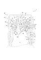
図1は、本発明の一実施形態である二重容器用キャップ1が、これに適合する二重容器本体2に装着された状態を示す。二重容器用キャップ1は、キャップ本体10、中栓20、移動弁体30、結合弁40、及び蓋体50で構成されている。また、二重容器本体2は、内層体3、及び外層体4で構成されている。なお、本明細書、特許請求の範囲、要約書および図面では、後述する蓋体50が位置する側を上方(図1における上側)とし、二重容器本体2が位置する側を下方(図1における下側)とする。
FIG. 1 shows a state in which a double container cap 1 according to an embodiment of the present invention is mounted on a double container main body 2 adapted to the cap. The double container cap 1 includes a
まず、二重容器本体2について説明する。本実施形態では、二重容器本体2は、内層体3の合成樹脂素材と外層体4の合成樹脂素材とを積層して形成されるパリソンに対し、押出しブロー成形を行うことによって積層剥離容器を形作っている。そして、二重容器本体2を構成する内層体3の材料にはエチレン―ビニルアルコール共重合樹脂(EVOH)又はナイロンを用いている。また、外層体4の材料には、低密度ポリエチレン(LDPE)又は高密度ポリエチレン樹脂(HDPE)を用いており、特にLDPEを用いた場合には高いスクイズ性を付与することができる。しかし、この態様に限定されず、例えば二軸延伸ブロー成形を行うことによって積層剥離容器を形成する場合には、内層体3の材料にはポリプロピレン(PP)を用い、外層体4の材料にはポリエチレンテレフタレート(PET)を用いてもよい。また、内層体3及び外層体4の材料には、相互に相溶性が低い他の樹脂を用いることができる。更に、二重容器本体2は、積層剥離容器ではなく、外層体4と内層体3とを個別に形成して組み付けるものであってもよい。また、図示は省略するが、内層体3と外層体4との間に、上下方向に延在して内層体3と外層体4とを部分的に接合する、1本或いは複数本の接着帯を設けてもよい。
First, the double container body 2 will be described. In the present embodiment, the double container main body 2 is formed by extruding and blowing a delamination container on a parison formed by laminating the synthetic resin material of the
内層体3は、減容変形可能に形成されるものであって、本実施形態では、積層状態で形成された二重容器本体2に対し、外層体4から剥離させることで得られるものである。内層体3は、その内側に内容物を収容する収容空間Sと、この収容空間Sにつながる上部開口3aを備えている。
The
外層体4は、円筒状の口部周壁4aに、図示を省略する復元自在な可撓性を有する胴部、及び胴部の下端を閉鎖する底部を連結したものである。口部周壁4aの外周面には雄ねじ部4bを設けている。また、口部周壁4aには、内層体3との相互間に空気を取り込むための貫通孔4cを設けていて、更に、貫通孔4cを設けた外周面には、上下方向に雄ねじ部4bを切り欠く溝部4dを設けている。
The outer layer body 4 is configured by connecting a cylindrical mouth
次に、二重容器用キャップ1に関し、キャップ本体10について説明する。キャップ本体10は、口部周壁4aを取り囲む外周壁11を備えていて、外周壁11の内周面には、口部周壁4aの雄ねじ部4bに対応する雌ねじ部12が形成されている。また、外周壁11の上部には、頂壁13が一体に連結している。頂壁13の上面には、注出筒14が設けられており、注出筒14の内周面には、内容物を注出する注出孔14aが形成されている。また、頂壁13の下面には、同心二重配置となる一対の上部嵌合壁15が設けられている。更に、上部嵌合壁15より径方向外側には、頂壁13を貫通する外気導入孔16を設けている。本実施形態では、頂壁13の中央部分と外周部分との間に段差を設け(中央部分に対し外周部分は高さが低くなっている)、この段差に径方向外側に向けて開口するようにして外気導入孔16を設けている。このように構成することで、頂壁13上に溢れた内容物が、外気導入孔16に入り難くなる。なお、外周壁11の下端は口部周壁4aと気密に当接していて、口部周壁4aと外周壁11との間には、貫通孔4cに通じる通気路Tが設けられている。
Next, the cap
なお、本実施形態では、上下方向に雄ねじ部4bを切り欠く溝部4dを通気路Tとして用いるように構成しているが、この態様には限定されない。溝部4dを設けず、雄ねじ部4bと雌ねじ部12の隙間を通気路Tとして用いてもよい。
In addition, in this embodiment, although it has comprised so that the
図1に示すように、リング形状の突起18が、頂壁13に対して注出筒14とは反対側に突出している。突起18は、後述する逆止弁弁体43aの上方への変位を規制している。
As shown in FIG. 1, a ring-shaped
キャップ本体10の内側には、中栓20が設けられる。中栓20は、注出孔14aと内層体3との間に位置するとともに、内層体3の上部開口3aを覆う隔壁21を備えている。
An
隔壁21には、一端に、注出孔14a側に開口する注出孔14a側開口を有すると共に、他端に、内層体3の収容空間S側に開口する内層体3側開口を有する筒状壁22が設けられている。本実施形態の筒状壁22は、図1に示すように、隔壁21の一部に貫通孔22aを設け、この貫通孔22aの縁部から収容空間Sに向けて円筒部22bを延在させ、傾斜部22cを介して、下端に貫通孔22dを有する円筒状の部位である。なお、本実施形態における注出孔14a側開口は貫通孔22aに対応し、内層体3側開口は貫通孔22dに対応する。また隔壁21には、筒状壁22に隣接してこの隔壁21を貫通する孔(連通口23)が設けられている。本実施形態では、連通口23は1つの筒状壁22に隣接した3箇所に設けられているが、連通口23及び筒状壁22の数はこの態様に限定されるものではない。ここで、筒状壁22における内層体3側開口(貫通孔22d)の総開口面積と、連通口23の総開口面積との関係は、連通口23の総開口面積の方が大きいことが好ましいが、必ずしもこれに限定されるものではない。なお、総開口面積とは、同種の開口が複数ある場合にはそれらの面積の総和を指すものとする。
The
また隔壁21は、連通口23より径方向外側において収容空間S側に屈曲する段部24を備えていて、段部24より径方向外側には、段部24との間で上向き開放の溝を形成する嵌合壁25が設けられている。そして隔壁21の下面には、外層体4との間で内層体3を挟み込む環状のシール壁26を設けている。なお、図1に示すように隔壁21の外縁には、少なくとも1つの溝27が設けられている。
Further, the
筒状壁22内には、本実施形態では球状となる移動弁体30が設けられている。筒状壁22と移動弁体30との間には、二重容器本体2の姿勢変更に応じて移動弁体30が移動可能、且つ内容物はほとんど通過させない(実質的に通過させない)程度の隙間が設けられている。なお、筒状壁22の注出孔14a側は、貫通孔22aによって開口し、収容空間S側は、貫通孔22dによって開口しているので、筒状壁22内に入り込んだ内容物が移動弁体30の移動を妨げることはない。また移動弁体30は、二重容器本体2を起立姿勢(二重容器本体2の底部を水平な台の上に載置した状態の姿勢)にすることで、筒状壁22の傾斜部22cに着座する。これによって収容空間Sをシールすることができる。
In the
キャップ本体10と中栓20との間には、逆止弁43が設けられている。逆止弁43は、図2に示すように、結合弁40の一部として、円筒状の環状壁41の径方向内側に設けられている。逆止弁43は、図2に示すように、円板状の逆止弁弁体43aの外周縁の3箇所を逆止弁アーム43bによって支持された構造を有する、いわゆる三点弁である。外層体4のスクイズによって内層体3内の圧力が高まると、その圧力によって、逆止弁アーム43bの弾性力に抗して逆止弁弁体43aが図1の上方に持ち上げられ、隔壁21から離間することによって逆止弁43は開放状態となる。外層体4のスクイズが解除されると、逆止弁弁体43aに圧力がかからないので、逆止弁弁体43aは、自重及び逆止弁アーム43bの弾性力によって再び隔壁21に当接し、逆止弁43は閉塞する。
A
なお、本実施形態においては、逆止弁弁体43aを円板状部材で構成したが、この態様には限定されず、矩形形状等を有する部材であってもよい。また、逆止弁43は、必ずしも三点弁である必要はなく、二点弁や薄肉環状弁など、内層体3内の正圧によって開放される様々な弁を用いることができる。
In the present embodiment, the
一方、環状壁41の径方向外側には、図1及び図2に示すように、外気導入弁45が設けられている。外気導入弁45は、環状壁41の径方向外側に、円環状且つ薄肉の弁体45aをなして形成される。弁体45aは、内周側端部を環状壁41の外周面に連結させると共に、外周側端部をキャップ本体10の頂壁13の下面に着座させることにより、外気導入孔16を閉塞する。また、弁体45aの外周側端部は、図2に示すように、周上の対向する2箇所において2本の弾性アーム45bによって支持されている。なお、環状の弁体45aは、図1から分かるように、内層体3側に凸となる湾曲形状に形成されている。この湾曲形状の採用により、弁体45aは所定の負圧がかかるまで確実に外気導入弁45を閉塞状態に維持することができる。弾性アーム45bの外周端は、環状の周壁47に支持されている。この周壁47は、キャップ本体10の内周面に嵌合し、更に頂壁13の下面と隔壁21の上面によって上下から狭持され固定されている。
On the other hand, an outside
このように、本実施形態では、外気導入弁45を構成する弁体45aを薄肉の円環状部材で構成すると共に、弁体45aの外周側端部を弾性アーム45bで支持するようにしている。従って、弁体45aの外周側端部が特許文献1のように完全な自由端ではないので、二重容器本体2内に熱充填を行った際に、熱による弁体45aの外周側端部の変形を抑制することができる。また、弁体45aの外周側端部が弾性支持されているため、外気を導入する際に弁体45aに発生する振動を、弾性アーム45bによって吸収することができる。
Thus, in the present embodiment, the
なお、本実施形態においては、弁体45aが2箇所において弾性アーム45bによって支持されるように構成したが、弾性アーム45bの数は限定されず、例えば、3箇所以上において支持される構成としてもよい。また、弾性アーム45bは、周方向に等間隔で配置されるのが好ましいが、これに限定されるものではない。
In the present embodiment, the
また、本実施形態では、逆止弁43及び外気導入弁45を環状壁41と一体に設けるように構成したが、この態様には限定されない。例えば、逆止弁43が第1環状壁に設けられると共に、外気導入弁45が第2環状壁に設けられるようにして両者を別体に構成してもよい。また、逆止弁43及び外気導入弁45は、環状壁41以外のものに固定されていてもよい。
Further, in the present embodiment, the
本実施形態では、逆止弁弁体43aの閉塞時においても、貫通孔22aと注出孔14aとは、逆止弁アーム43bの幅方向両側の隙間を通じて連通している。これにより筒状壁22の貫通孔22aは常時開放される。逆止弁43は、図1に示すようにキャップ本体10、中栓20に対して取り付けた際、環状壁41の下部が段部24と嵌合壁25との間で嵌合保持され、環状壁41の上部が一対の上部嵌合壁15で嵌合保持されるようになっている。これにより、図1に示すように、環状壁41の径方向内側には、連通口23と注出孔14aとを連通させて内容物の流路を形成する内側空間K1が区画形成され、環状壁41の径方向外側には、外気導入孔16と溝27とを連通させて空気の流路を形成する外側空間K2が区画形成される。
In the present embodiment, even when the check
蓋体50は、図1に示すように、ヒンジ51を介してキャップ本体10の外周壁11に連結していて、ヒンジ51で折り曲げることで、注出孔14a及び外気導入孔16を覆い隠すことができる。より詳細には、蓋体50は、平板状の上壁52と、上壁52の縁部に連結するとともに外周壁11に連なる形状となる蓋体周壁53とを備えている。また、上壁52には、蓋体50を閉めた際に注出筒14の内側に入り込んで注出孔14aをシールする筒状のシール部54が設けられている。周上のヒンジ51とは対向する側の蓋体周壁53の上端には、外周方向に突出する把持部58が設けられている、利用者は、この把持部58を把持して蓋体50を上方に持ち上げて開放したり、下方に押し下げて閉塞することができる。なお、蓋体50が閉塞される際は、蓋体周壁53及び内周壁56の内周面が、突壁11a及び頂壁段部13aにそれぞれアンダーカット係合して、蓋体50はキャップ本体10に対してしっかりと係合する。なお、蓋体50は、ヒンジ51を設けずにキャップ本体10とは別体のものとし、ねじやアンダーカットでキャップ本体10に装着するように構成してもよい。
As shown in FIG. 1, the
上記のように構成される二重容器用キャップ1から内容物を吐出するにあたっては、図1の状態から蓋体50を開き、二重容器本体2を起立姿勢から傾倒姿勢に姿勢変更して、外層体4の胴部を押圧(スクイズ)する。これにより、筒状壁22内の移動弁体30は注出孔14a側に移動し、また、内層体3と外層体4との間の空気を介して収容空間Sが加圧される。なお、外層体4の胴部を押圧しているときは、貫通孔4c、通気路T、及び溝27を通じて弁体45aにも下方から圧力がかかるため、外気導入弁45は閉塞状態に維持される。従って、外層体4を押圧しても、内層体3と外層体4との間の空気が外気導入孔16から漏れ出すことはなく、収容空間Sへの加圧が阻害されることはない。そして、収容空間S内の正圧が、逆止弁弁体43aを持ち上げるため、内容物は連通口23から流出し、内側空間K1を経由して注出孔14aから外部に注出される。ここで、筒状壁22における内層体3側の開口(貫通孔22d)の総開口面積に対し、連通口23の総開口面積を大きくしているので、内容物が流れる際、連通口23での抵抗がより軽減されてスムーズに注出させることができる。
In discharging the contents from the double container cap 1 configured as described above, the
なお、筒状壁22内に収容された移動弁体30は、二重容器本体2が倒立姿勢となり、外層体4の胴部が押圧された際に注出孔14a側に移動するが、突部22eと接触することによって筒状壁22からの飛び出しを防止している。
The
所要量の内容物を注出した後は、外層体4の胴部への押圧を解除する。これによって収容空間S内の正圧が外気圧へと戻り、逆止弁弁体43aが連通口23を再び閉鎖するので、収容空間S内への外気の入り込みが防止できる。また、外層体4は、それ自身の復元力により元の形状に戻ろうとするため、内層体3と外層体4との間の空間は負圧となる。これによって、貫通孔4c、通気路T、及び溝27を通じて外気導入弁45の下方も負圧となるため、弁体45aは下方に引かれて外気導入弁45は開放状態になる。外気導入弁45の開放に伴い、外気導入孔16から空気が流入し、外側空間K2、溝27、及び通気路Tを経由して、貫通孔4cより外層体4と内層体3の間の空間に空気が導入される。これにより、内層体3を減容変形させたまま外層体4が復元することができる。
After the required amount of content has been poured out, the pressure on the body of the outer layer body 4 is released. As a result, the positive pressure in the storage space S returns to the external pressure, and the
逆止弁弁体43aが連通口23を閉鎖すると、注出筒14及び内側空間K1内には内容物が残留したままになっているものの、二重容器本体2を元の起立姿勢に戻すと、移動弁体30は、自重等によって内層体3の収容空間S側に移動する。これにより、筒状壁22における注出孔14a側には、スペースが生じることになるため、注出筒14及び内側空間K1内に残留した内容物を、貫通孔22aを通して筒状壁22側に移動させることができ(サックバック機能)、液だれを有効に防止することができる。
When the
以上のように、本実施形態によれば、外気導入弁45の弁体45aとして、薄肉の環状弁体を採用し、弁体45aの外周側端部が弾性アーム45bによって上下に変位可能に支持されるように構成した。これによって、弁体45aの外周側端部が完全な自由端ではないので、二重容器本体2内に熱充填を行った際に、熱によって弁体45aが変形するのを抑制することができる。また、弁体45aの外周側端部が弾性支持されているため、外気を導入する際に、弁体45aに発生する振動を弾性アーム45bによって吸収することができる。
As described above, according to the present embodiment, a thin annular valve body is employed as the
また、本実施形態によれば、隔壁21に筒状壁22を設けて、二重容器本体2を倒立姿勢から起立姿勢に戻したときに、筒状壁22内の移動弁体30が、自重等により注出孔14a側から内層体3側に移動するように構成した。これによって、注出筒14及び内側空間K1内の内容物をサックバック機能によって内層体3側に引き戻すことができる。
Further, according to the present embodiment, when the
また、本実施形態によれば、外気導入弁45の弁体45aを、内層体3側に凸となる湾曲形状を有するように構成した。これによって、所定の負圧がかかるまで、外気導入弁45を閉塞状態に維持することができる。
Further, according to the present embodiment, the
また、本実施形態によれば、外気導入弁45の弁体45aが外周側端部において2本以上の弾性アーム45bによって支持されるように構成した。これによって、弁体45aの外周側端部がバランス良く支持され、弁体45aの意図しない傾きや変形を抑制することができる。
Moreover, according to this embodiment, it comprised so that the
また、本実施形態によれば、環状壁41に対して逆止弁43及び外気導入弁45を一体に設けたので、部品点数を削減し、二重容器用キャップ1の組立工数を削減することができる。
Moreover, according to this embodiment, since the
本発明に従う二重容器用キャップ1は、上述した実施形態に限定されるものではなく、特許請求の範囲に従う範囲で種々の変更が可能である。例えば、移動弁体30の断面形状は、筒状壁22の断面形状に合わせて適宜変更することができる。また、筒状壁22及び移動弁体30は必ずしも設けなくてもよい。また、外層体4及び内層体3は、積層構造のパリソンをブロー成形することによって形成されるものに限られず、外層体4及び内層体3を個別に形成し、その後、内層体3を外層体4内に装着するようにしたものでもよい。
The double container cap 1 according to the present invention is not limited to the above-described embodiment, and various modifications can be made within the scope according to the claims. For example, the cross-sectional shape of the moving
本発明によれば、外気導入弁45の安定動作が可能な、新規の二重容器用キャップ1を提供することが可能となる。
According to the present invention, it is possible to provide a novel double-container cap 1 in which the outside
1 二重容器用キャップ
2 二重容器本体
3 内層体
3a 上部開口
4 外層体
4a 口部周壁(口部)
4b 雄ねじ部
4c 貫通孔
4d 溝部
10 キャップ本体
11 外周壁
11a 突壁
12 雌ねじ部
13 頂壁
13a 頂壁段部
14 注出筒
14a 注出孔
15 上部嵌合壁
16 外気導入孔
18 突起
20 中栓
21 隔壁
22 筒状壁
22a 貫通孔(注出孔側開口)
22b 円筒部
22c 傾斜部
22d 貫通孔(内層体側開口)
22e 突部
23 連通口
24 段部
25 嵌合壁
26 シール壁
27 溝
30 移動弁体
40 結合弁
41 環状壁
43 逆止弁
43a 逆止弁弁体
43b 逆止弁アーム
45 外気導入弁
45a 弁体
45b 弾性アーム
47 周壁
50 蓋体
51 ヒンジ
52 上壁
53 蓋体周壁
54 シール部
56 内周壁
58 把持部
K1 内側空間
K2 外側空間
S 収容空間
T 通気路
DESCRIPTION OF SYMBOLS 1 Double container cap 2 Double container
4b Male thread part 4c Through
Claims (5)
前記内層体からの内容物を注出する注出孔を有し、前記外層体の口部に装着されるキャップ本体と、
前記注出孔と前記内層体との間に位置する隔壁を有し、該隔壁に、内容物を通す連通口を備える中栓と、
前記連通口を閉鎖する一方、前記外層体のスクイズによる前記内層体内の圧力上昇によって前記連通口を開放して内容物を通過させる逆止弁と、
前記外層体のスクイズ解除による復元に伴って開放され、前記キャップ本体に形成された外気導入孔を通して前記外層体と前記内層体との間の空間に外気を導入する外気導入弁と
を備え、
前記外気導入弁は薄肉の環状をなす弁体を有し、該弁体の外周側端部が弾性アームによって上下方向に変位可能に支持され、該外周側端部が前記キャップ本体に着座して前記外気導入孔を閉鎖する、二重容器用キャップ。 A double container cap mounted on a double container body comprising an inner layer body for containing contents and a squeezable outer layer body for containing the inner layer body,
A cap body having a pouring hole for pouring contents from the inner layer body, and attached to the mouth of the outer layer body;
An inner plug having a partition wall positioned between the extraction hole and the inner layer body, and having a communication port through which the contents are passed,
A check valve that closes the communication port and opens the communication port due to a pressure increase in the inner layer body due to the squeeze of the outer layer body to pass the contents;
An outside air introduction valve that is opened in association with restoration by squeezing the outer layer body and introduces outside air into a space between the outer layer body and the inner layer body through an outside air introduction hole formed in the cap body,
The outside air introduction valve has a thin annular valve body, the outer peripheral side end of the valve body is supported by an elastic arm so as to be vertically displaceable, and the outer peripheral side end is seated on the cap body. A double container cap for closing the outside air introduction hole.
該筒状壁内には、上下方向に移動可能な移動弁体が設けられている、請求項1に記載の二重容器用キャップ。 The partition further comprises a cylindrical wall having an opening on the outlet side on one end and an inner layer side opening on the other end,
The double container cap according to claim 1, wherein a moving valve body movable in the vertical direction is provided in the cylindrical wall.
Priority Applications (1)
| Application Number | Priority Date | Filing Date | Title |
|---|---|---|---|
| JP2016072587A JP6559089B2 (en) | 2016-03-31 | 2016-03-31 | Double container cap |
Applications Claiming Priority (1)
| Application Number | Priority Date | Filing Date | Title |
|---|---|---|---|
| JP2016072587A JP6559089B2 (en) | 2016-03-31 | 2016-03-31 | Double container cap |
Publications (2)
| Publication Number | Publication Date |
|---|---|
| JP2017178436A JP2017178436A (en) | 2017-10-05 |
| JP6559089B2 true JP6559089B2 (en) | 2019-08-14 |
Family
ID=60003377
Family Applications (1)
| Application Number | Title | Priority Date | Filing Date |
|---|---|---|---|
| JP2016072587A Active JP6559089B2 (en) | 2016-03-31 | 2016-03-31 | Double container cap |
Country Status (1)
| Country | Link |
|---|---|
| JP (1) | JP6559089B2 (en) |
Family Cites Families (4)
| Publication number | Priority date | Publication date | Assignee | Title |
|---|---|---|---|---|
| AU2135795A (en) * | 1994-03-25 | 1995-10-17 | S Design Udo Suffa Gmbh | Closure |
| JP4798627B2 (en) * | 2006-08-31 | 2011-10-19 | 株式会社吉野工業所 | Mixing container |
| JP6200639B2 (en) * | 2012-09-28 | 2017-09-20 | 株式会社吉野工業所 | Discharge container |
| JP6533032B2 (en) * | 2014-02-28 | 2019-06-19 | 株式会社吉野工業所 | Double container |
-
2016
- 2016-03-31 JP JP2016072587A patent/JP6559089B2/en active Active
Also Published As
| Publication number | Publication date |
|---|---|
| JP2017178436A (en) | 2017-10-05 |
Similar Documents
| Publication | Publication Date | Title |
|---|---|---|
| JP6762669B2 (en) | Double container cap | |
| JP6352116B2 (en) | Double container cap | |
| JP2016193749A (en) | Double container | |
| JP6612115B2 (en) | Container with soy sauce | |
| JP2017132529A (en) | Discharge container | |
| JP6100059B2 (en) | Dispensing container | |
| JP6710468B2 (en) | Discharge container | |
| JP6868445B2 (en) | Weighing container | |
| JP7264723B2 (en) | Drain cap for double container and double container | |
| JP2018002232A (en) | Double container | |
| JP6559089B2 (en) | Double container cap | |
| JP7058922B2 (en) | Manufacturing method for double container caps and double container caps | |
| JP6716341B2 (en) | Double container | |
| JP6355576B2 (en) | Double container | |
| JP7058919B2 (en) | Double container cap | |
| JP6651409B2 (en) | Double container cap | |
| JP7058920B2 (en) | Double container cap | |
| JP2018090285A (en) | Hinge cap | |
| JP6672062B2 (en) | Double container cap | |
| JP6896342B2 (en) | Double container cap | |
| JP6501698B2 (en) | Double container cap | |
| JP2005103153A (en) | Chemical liquid container | |
| JP6883945B2 (en) | Double container cap | |
| JP7365144B2 (en) | Pour cap for double container and double container | |
| JP7072975B2 (en) | Double container |
Legal Events
| Date | Code | Title | Description |
|---|---|---|---|
| A621 | Written request for application examination |
Free format text: JAPANESE INTERMEDIATE CODE: A621 Effective date: 20181003 |
|
| A977 | Report on retrieval |
Free format text: JAPANESE INTERMEDIATE CODE: A971007 Effective date: 20190708 |
|
| TRDD | Decision of grant or rejection written | ||
| A01 | Written decision to grant a patent or to grant a registration (utility model) |
Free format text: JAPANESE INTERMEDIATE CODE: A01 Effective date: 20190716 |
|
| A61 | First payment of annual fees (during grant procedure) |
Free format text: JAPANESE INTERMEDIATE CODE: A61 Effective date: 20190716 |
|
| R150 | Certificate of patent or registration of utility model |
Ref document number: 6559089 Country of ref document: JP Free format text: JAPANESE INTERMEDIATE CODE: R150 |