JP6558195B2 - Vehicle front structure - Google Patents
Vehicle front structure Download PDFInfo
- Publication number
- JP6558195B2 JP6558195B2 JP2015198527A JP2015198527A JP6558195B2 JP 6558195 B2 JP6558195 B2 JP 6558195B2 JP 2015198527 A JP2015198527 A JP 2015198527A JP 2015198527 A JP2015198527 A JP 2015198527A JP 6558195 B2 JP6558195 B2 JP 6558195B2
- Authority
- JP
- Japan
- Prior art keywords
- vehicle
- wall portion
- width direction
- fender
- opening
- Prior art date
- Legal status (The legal status is an assumption and is not a legal conclusion. Google has not performed a legal analysis and makes no representation as to the accuracy of the status listed.)
- Expired - Fee Related
Links
- 230000001012 protector Effects 0.000 claims description 59
- 230000006866 deterioration Effects 0.000 description 8
- 230000000052 comparative effect Effects 0.000 description 5
- 230000001629 suppression Effects 0.000 description 4
- 239000000463 material Substances 0.000 description 2
- 230000004048 modification Effects 0.000 description 2
- 238000012986 modification Methods 0.000 description 2
- 239000003566 sealing material Substances 0.000 description 2
- 238000003466 welding Methods 0.000 description 2
- 210000000078 claw Anatomy 0.000 description 1
- 230000000694 effects Effects 0.000 description 1
- 238000009957 hemming Methods 0.000 description 1
- 230000035939 shock Effects 0.000 description 1
- 239000000725 suspension Substances 0.000 description 1
Images


Description
本発明は、車両前部構造に関する。 The present invention relates to a vehicle front structure.
下記特許文献1には、フェンダパネルの内側の端部に被覆部材(フェンダプロテクタ)の基端部が取り付けられると共に、被覆部材が車両下方側へ垂下されて先端部が自由端とされた構造が開示されている。この構造では、被覆部材が、略車両前後方向に連続して延在しており、フェンダパネルの内側の端末部及びフェンダパネルの下方側に取り付けられた衝撃吸収部を車両幅方向内側から覆い隠している。なお、フェンダパネルに取り付けられるフェンダプロテクタ又はフェンダカバーに関する構造として、特許文献2、3に記載されたものがある。 The following Patent Document 1 has a structure in which a base end portion of a covering member (fender protector) is attached to an inner end portion of a fender panel, and the covering member is suspended downward from the vehicle so that a distal end portion is a free end. It is disclosed. In this structure, the covering member extends substantially continuously in the vehicle front-rear direction, and covers the terminal portion inside the fender panel and the shock absorbing portion attached to the lower side of the fender panel from the vehicle width direction inner side. ing. In addition, there exist some which were described in patent document 2, 3 as a structure regarding the fender protector or fender cover attached to a fender panel.
上記特許文献1に記載の構造では、例えば、歩行者保護時において、被覆部材の縦壁部に荷重調整用の開口部を設定する場合、開口部の見栄えが悪く、対応が必要である。 With the structure described in Patent Document 1, for example, when an opening for load adjustment is set in the vertical wall portion of the covering member when protecting a pedestrian, the appearance of the opening is poor, and it is necessary to deal with it.
本発明は上記事実を考慮し、歩行者保護と、フェンダプロテクタ本体の開口部による見栄えの悪化の抑制とを両立することができる車両前部構造を得ることが目的である。 In view of the above facts, the present invention has an object to obtain a vehicle front structure that can achieve both pedestrian protection and suppression of deterioration in appearance due to an opening of a fender protector body.
第1の態様に係る車両前部構造は、車両前部の側面を構成するフェンダパネルの車両内側の端部に取り付けられる上壁部と、前記上壁部の車両内側の端部から車両下方側に延出されるカバー部と、を備えたフェンダプロテクタ本体と、前記カバー部に設けられた車両前後方向に沿った複数の開口部と、を有する。 The vehicle front portion structure according to the first aspect includes an upper wall portion attached to an end portion on the vehicle inner side of a fender panel constituting a side surface of the vehicle front portion, and a vehicle lower side from the vehicle inner end portion of the upper wall portion. A fender protector main body including a plurality of openings along the vehicle front-rear direction provided in the cover portion.
第1の態様に係る車両前部構造によれば、フェンダプロテクタ本体には、フェンダパネルの車両内側の端部に取り付けられる上壁部と、上壁部の車両内側の端部から車両下方側に延出されるカバー部とが備えられている。さらに、カバー部には、車両前後方向に沿って複数の開口部が設けられている。これにより、車両上方からの荷重に対してカバー部が容易に車両上下方向に圧縮して変形する。また、カバー部の開口部によって、車両上方からの荷重に対してフェンダプロテクタ本体の弱体化が可能となり、歩行者保護時の荷重調整を行うことができる。 According to the vehicle front structure according to the first aspect , the fender protector main body includes an upper wall portion attached to the vehicle inner end portion of the fender panel, and the vehicle inner end portion of the upper wall portion on the vehicle lower side. And an extended cover part. Furthermore, the cover part is provided with a plurality of openings along the vehicle front-rear direction. As a result, the cover portion is easily compressed and deformed in the vehicle vertical direction with respect to the load from above the vehicle. In addition, the opening of the cover part can weaken the fender protector body against the load from above the vehicle, and the load can be adjusted when protecting the pedestrian.
第2の態様に係る車両前部構造は、第1の態様に記載の車両前部構造において、前記カバー部に設けられ、前記上壁部の車両内側の端部から車両下方内側に傾斜した第1傾斜部と、前記カバー部の前記第1傾斜部と連続して設けられ、前記第1傾斜部の下端部から車両下方外側に傾斜した第2傾斜部と、前記カバー部の前記第2傾斜部と連続して設けられ、前記第2傾斜部の下端部から車両下方側又は車両下方内側に延びると共に複数の前記開口部を備えた縦壁部と、前記カバー部における前記開口部の上縁部から車両下方側かつ前記開口部の車両外側に延びると共に、下端部の第1辺が前記開口部の下縁部の第2辺よりも車両下方に配置された延出部と、を有する。
第2の態様に係る車両前部構造によれば、フェンダプロテクタ本体のカバー部には、上壁部から車両下方内側に傾斜した第1傾斜部と、第1傾斜部の下端部から車両下方外側に傾斜した第2傾斜部と、第2傾斜部の下端部から車両下方側又は車両下方内側に延びた縦壁部が設けられている。これにより、車両上方からの荷重に対してカバー部が容易に車両上下方向に圧縮して変形する。さらに、縦壁部には、車両前後方向に沿って複数の開口部が設けられている。これにより、縦壁部の開口部によって、車両上方からの荷重に対してフェンダプロテクタ本体の弱体化が可能となり、歩行者保護時の荷重調整を行うことができる。
また、フェンダプロテクタ本体のカバー部は、第2傾斜部の下端部から車両下方側又は車両下方内側に延びると共に車両前後方向に沿って複数の開口部を備えた縦壁部と、開口部の上縁部から車両下方側かつ開口部の車両外側に延びた延出部と、を有しており、延出部の下端部の第1辺が開口部の下縁部の第2辺よりも車両下方に配置されている。これによって、車両内側からの視線方向にて開口部の内部が見えにくくなり、フェンダプロテクタ本体の開口部による見栄えの悪化を抑制することができる。
A vehicle front structure according to a second aspect is the vehicle front structure according to the first aspect , wherein the vehicle front structure is provided on the cover portion, and is inclined inwardly from the vehicle inner end of the upper wall portion to the vehicle lower inner side. A first inclined portion, a second inclined portion provided continuously with the first inclined portion of the cover portion, and inclined downward from the lower end portion of the first inclined portion toward the vehicle lower side; and the second inclined portion of the cover portion. A vertical wall portion that is provided continuously from the lower end portion and extends from the lower end portion of the second inclined portion toward the vehicle lower side or the vehicle lower inner side and includes a plurality of the opening portions, and the upper edge of the opening portion in the cover portion And an extension portion that extends to the vehicle lower side of the opening and the vehicle outer side of the opening, and the first side of the lower end portion is disposed below the second side of the lower edge of the opening.
According to the vehicle front structure according to the second aspect, the cover portion of the fender protector main body includes a first inclined portion that is inclined from the upper wall portion to the vehicle lower inner side, and a vehicle lower outer side from the lower end portion of the first inclined portion. And a vertical wall portion extending from the lower end portion of the second inclined portion to the vehicle lower side or the vehicle lower inner side. As a result, the cover portion is easily compressed and deformed in the vehicle vertical direction with respect to the load from above the vehicle. Further, the vertical wall portion is provided with a plurality of openings along the longitudinal direction of the vehicle. Thereby, the fender protector main body can be weakened against the load from above the vehicle by the opening of the vertical wall portion, and the load adjustment at the time of pedestrian protection can be performed.
The cover portion of the fender protector main body extends from the lower end of the second inclined portion to the vehicle lower side or the vehicle lower inner side, and has a vertical wall portion having a plurality of openings along the vehicle front-rear direction, and an upper portion of the opening. An extended portion extending from the edge to the vehicle lower side and the vehicle outside of the opening, and the first side of the lower end of the extended portion is more vehicle than the second side of the lower edge of the opening. It is arranged below. This makes it difficult to see the inside of the opening in the direction of the line of sight from the inside of the vehicle, and deterioration of the appearance due to the opening of the fender protector body can be suppressed.
本発明に係る車両前部構造によれば、歩行者保護と、フェンダプロテクタ本体の開口部による見栄えの悪化の抑制とを両立することができる。 According to the vehicle front structure according to the present invention, it is possible to achieve both pedestrian protection and suppression of deterioration in appearance due to the opening of the fender protector main body.
以下、図1〜図5を用いて、本発明に係る車両前部構造の第1実施形態について説明する。なお、これらの図において適宜示される矢印RRは車両後方側を示しており、矢印UPは車両上方側を示しており、矢印OUTは車両幅方向外側を示している。 Hereinafter, a first embodiment of a vehicle front structure according to the present invention will be described with reference to FIGS. Note that an arrow RR appropriately shown in these drawings indicates the vehicle rear side, an arrow UP indicates the vehicle upper side, and an arrow OUT indicates the vehicle width direction outer side.
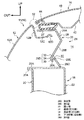
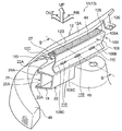
図1には、本実施形態に係る車両前部構造24がフードを省略した状態で車両幅方向内側の斜め前方側から見た斜視図にて示されている。図2には、車両前部構造24がフードを省略しない状態で断面図(図1中の2−2線に沿った断面図)にて示されている。図1及び図2に示されるように、自動車の車両10の前部11の側部には、フェンダパネルとしてのフロントフェンダパネル12が略車両前後方向に沿って配設されている。車両10の前部11には、フロントフェンダパネル12の車両幅方向内側にエンジンルーム14が設けられており、エンジンルーム14の車両上方側には、エンジンルーム14を開閉可能に覆うフード16(図2参照)が設けられている。なお、図1及び図2では、車両正面視にて車両10の前部11の車両幅方向の左側端部のみが図示されているが、車両10の前部11の車両幅方向両端部は左右対称であるので、車両正面視にて車両10の前部11の車両幅方向の右側端部は図示を省略する。
FIG. 1 is a perspective view of a vehicle
フロントフェンダパネル12は、車両10の前部11の側面を構成する外側壁部12Aと、外側壁部12Aの車両上下方向の上端部から略車両下方側に延びた縦壁部12Bと、縦壁部12Bの下端部から略車両幅方向内側に延びた端部としての横壁部12Cと、を備えている。さらに、フロントフェンダパネル12は、横壁部12Cの車両幅方向内側の端部に車両上方側に凸状となるように湾曲された略半円状の端末部12Dを備えている。フロントフェンダパネル12の外側壁部12Aは、車両上下方向の上部側が下部側に対して車両幅方向内側に湾曲しており、車両10の側部の意匠面を構成している。
The
図2に示されるように、フード16は、フード16の外板を構成するフードアウタパネル40と、フード16に対してフード下方側へ離間して配置されてフード16の内板を構成するフードインナパネル42と、を備えている。フードアウタパネル40の外周部は、フードインナパネル42にヘミング加工によって結合されている。フード16のフードアウタパネル40と、フロントフェンダパネル12の外側壁部12Aとの境界となる見切り部52は、フード16の車両幅方向外側端部において、略車両前後方向に沿って配置されている。
As shown in FIG. 2, the
図1及び図2に示されるように、車両10の前部11には、フロントフェンダパネル12の横壁部12Cの車両下方側に、略車両前後方向に沿って延在されるエプロンアッパメンバ18が配設されている。エプロンアッパメンバ18は、フロントフェンダパネル12の外側壁部12Aの車両幅方向内側において、略車両前後方向を長手方向として配置される車両骨格部材である。エプロンアッパメンバ18は、車両幅方向外側に配置されるエプロンアッパメンバアウタ20と、車両幅方向内側に配置されてエプロンアッパメンバアウタ20と共に閉断面を構成するエプロンアッパメンバインナ22と、を備えている。エプロンアッパメンバアウタ20とエプロンアッパメンバインナ22は、それぞれの断面形状が車両幅方向外側に開口する略U字状に形成されている。エプロンアッパメンバインナ22の車両幅方向外側の上下の端末部22Aの内部側に、エプロンアッパメンバアウタ20の上下の端末部20Aの外部側が重ね合わされている。この状態で、上側の端末部22A、20Aが溶接等により接合されると共に、下側の端末部22A、20Aが溶接等により接合されていることで、エプロンアッパメンバアウタ20とエプロンアッパメンバインナ22とが閉断面構造に構成されている。
As shown in FIGS. 1 and 2, an apron
フロントフェンダパネル12の外側壁部12Aは、エプロンアッパメンバ18の車両幅方向外側に配置されており、フロントフェンダパネル12の横壁部12Cは、エプロンアッパメンバ18から車両上方側に離間して配置されている。フロントフェンダパネル12の横壁部12Cとエプロンアッパメンバ18との間の一定隙は、衝突時におけるフロントフェンダパネル12の変形可能空間を形成し、歩行者保護に対する要求性能を確保するための隙間となっている。
The
フロントフェンダパネル12の車両前後方向の後部側には、外側壁部12Aの上端部から車両下方側に延びた取付部12Eが設けられている。取付部12Eは、車両前後方向から見て車両幅方向内側に略L字状に屈曲されており、図示しない車体に締結具によって固定されている。なお、図示を省略するが、フロントフェンダパネル12をエプロンアッパメンバ18に衝撃吸収ブラケットにより取り付けてもよい。
A mounting
本実施形態の車両前部構造24は、フロントフェンダパネル12の横壁部12Cの車両上方側からエプロンアッパメンバ18の車両上方側に跨って配置されたフェンダプロテクタ本体としてのフェンダプロテクタ26を備えている。フェンダプロテクタ26は、略車両前後方向に沿って延在されており、フロントフェンダパネル12の横壁部12C及びエプロンアッパメンバ18に図示しない複数の取付部(例えば、係止爪など)により取り付けられている。
The vehicle
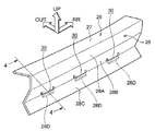
フェンダプロテクタ26は、フロントフェンダパネル12の車両内側(車両幅方向内側)の横壁部12Cに取り付けられる上壁部27と、上壁部27の車両幅方向内側の端部から車両下方側に延出されるカバー部28と、を備えている。図3及び図4にも示されるように、カバー部28は、上壁部27の車両幅方向内側の端部から車両下方内側(車両下方かつ車両幅方向内側)に傾斜した第1傾斜部28Aと、第1傾斜部28Aと連続して設けられると共に第1傾斜部28Aの下端部から車両下方外側(車両下方かつ車両幅方向外側)に傾斜した第2傾斜部28Bと、を備えている。また、カバー部28は、第2傾斜部28Bと連続して設けられると共に第2傾斜部28Bの下端部から車両下方内側(車両下方かつ車両幅方向内側)に延びた縦壁部28Cを備えている。縦壁部28Cの上部には、略車両前後方向に沿って複数の開口部30が設けられている。
The
言い換えると、カバー部28は、上壁部27から第1の高さH1まで車両下方かつ車両幅方向内側に傾斜した第1傾斜部28Aと、第1傾斜部28Aの下部側に第1の高さH1から第2の高さH2までの間で車両下方かつ車両幅方向外側に傾斜した第2傾斜部28Bと、を備えている(図4参照)。また、カバー部28は、第2傾斜部28Bの下部側に第2の高さH2から車両下方かつ車両幅方向内側に延びると共に略車両前後方向に沿って複数の開口部30を備えた縦壁部28Cを備えている(図4参照)。開口部30は、車両幅方向内側から見た状態で、略車両前後方向に長い略矩形状に形成されている。
In other words, the
さらに、カバー部28は、第2傾斜部28Bの下端部に、開口部30の上縁部から車両下方側かつ開口部30の車両外側(車両幅方向外側)に延びた延出部28Dを備えている。本実施形態では、延出部28Dは、車両前後方向から見た状態で、略L字状に形成されている。より具体的には、延出部28Dは、第2傾斜部28Bと連続して第2傾斜部28Bの延長線上に配置された壁部32と、壁部32の下端部から屈曲部34を介して車両下方側及び車両幅方向内側に延びた下側壁部36と、を備えている。延出部28Dは、下側壁部36の下端部の第1辺36Aが開口部30の下縁部の第2辺28Eよりも車両下方に配置されている(図2及び図4参照)。
Furthermore, the
フェンダプロテクタ26の上壁部27の上面には、略車両前後方向に沿って延在される長尺状のシール材44が取り付けられている。シール材44は、ゴム等の弾性部材で構成されており、車両幅方向に沿った断面にて中空状に形成されている。シール材44は、図示しないクリップ等によりフェンダプロテクタ26の上壁部27に取り付けられている。シール材44は、フード16が閉止されときに、フード16のフードインナパネル42の車両幅方向外側の端部に弾性変形した状態で圧接されるようになっている(図2参照)。
On the upper surface of the
車両10の前部11には、フロントフェンダパネル12の車両前方側にフロントランプ46が設けられている。図示を省略するが、フロントランプ46は、車体に取付具により固定されている。また、エプロンアッパメンバ18の車両幅方向内側には、サスペンションタワー48が設けられている。
A
次に、本実施形態の車両前部構造24の作用及び効果について説明する。
Next, the operation and effect of the
図1〜図4に示されるように、車両前部構造24では、略車両前後方向に沿って延在されるフェンダプロテクタ26が設けられている。フェンダプロテクタ26は、フロントフェンダパネル12の車両内側(車両幅方向内側)の横壁部12Cに取り付けられる上壁部27と、上壁部27の車両内側(車両幅方向内側)の端部から車両下方側に延出されるカバー部28と、を備えている。カバー部28は、上壁部27の車両幅方向内側の端部から車両下方内側(車両下方かつ車両幅方向内側)に傾斜した第1傾斜部28Aと、第1傾斜部28Aと連続して設けられると共に第1傾斜部28Aの下端部から車両下方外側(車両下方かつ車両幅方向外側)に傾斜した第2傾斜部28Bと、を備えている。また、カバー部28は、第2傾斜部28Bの下端部から車両下方内側(車両下方かつ車両幅方向内側)に延びた縦壁部28Cを備えている。
As shown in FIGS. 1 to 4, the vehicle
この車両前部構造24では、図5に示されるように、フェンダプロテクタ26の車両上方側から衝突体60が衝突したとき、カバー部28が容易に車両上下方向に圧縮して変形する。さらに、縦壁部28Cには、略車両前後方向に沿って複数の開口部30が設けられている。これにより、縦壁部28Cの複数の開口部30によって、車両上方側からの荷重に対してフェンダプロテクタ26の弱体化が可能となり、フェンダプロテクタ26が変形しやすくなる。このため、フェンダプロテクタ26の縦壁部28Cの複数の開口部30によって、歩行者保護時の荷重調整を行うことができる。
In the
また、フェンダプロテクタ26のカバー部28は、第2傾斜部28Bの下端部から車両下方かつ車両幅方向内側に延びると共に略車両前後方向に沿って複数の開口部30を備えた縦壁部28Cと、開口部30の上縁部から車両下方側かつ開口部30の車両幅方向外側に延びた延出部28Dと、を備えている。その際、延出部28Dは、下端部の第1辺36Aが開口部30の下縁部の第2辺28Eよりも車両下方に配置されている(図2及び図4参照)。これによって、車両内側(車両幅方向内側)からの視線方向にて開口部30の内部が見えにくくなり、フェンダプロテクタ26の開口部30による見栄えの悪化を抑制することができる。
Further, the
したがって、車両前部構造24では、歩行者保護と、フェンダプロテクタ26の開口部30による見栄えの悪化の抑制とを両立することができる。
Therefore, in the vehicle
図8には、比較例の車両前部構造100が車両内側斜め前方から見た斜視図にて示されている。図9には、比較例の車両前部構造100が図8中の9−9線に沿った断面図にて示されている。
FIG. 8 is a perspective view of the
図8及び図9に示されるように、比較例の車両前部構造100は、フロントフェンダパネル12の車両幅方向内側に、略車両前後方向に沿って延在されるフェンダプロテクタ106を備えている。フェンダプロテクタ106は、フロントフェンダパネル12の横壁部12C及びエプロンアッパメンバ18に図示しない複数の取付具により取り付けられている。
As shown in FIGS. 8 and 9, the
フェンダプロテクタ106は、フロントフェンダパネル12の横壁部12Cに取り付けられる上壁部27と、上壁部27の車両幅方向内側の端部から車両下方側に延出されるカバー部108と、を備えている。カバー部108は、上壁部27の車両幅方向内側の端部から車両下方かつ車両幅方向内側に傾斜した第1傾斜部108Aと、第1傾斜部108Aの下端部から車両下方かつ車両幅方向外側に傾斜した第2傾斜部108Bと、を備えている。また、カバー部108は、第2傾斜部108Bの下端部から車両下方かつ車両幅方向内側に傾斜した第3傾斜部108Cを備えている。第2傾斜部108Bと第3傾斜部108Cとの稜線部108Dに跨った位置には、略車両前後方向に沿って複数の開口部110が設けられている。開口部110は、略車両前後方向を長手方向として配置された長円状に形成されている。
The
このような車両前部構造100では、第2傾斜部108Bと第3傾斜部108Cとの稜線部108Dに跨った位置に、略車両前後方向に沿って複数の開口部110が設けられている。このため、フェンダプロテクタ106に車両上方側から荷重が作用したときに、複数の開口部110によりフェンダプロテクタ106を弱体化させることができ、歩行者保護時の荷重調整が可能である。しかし、車両幅方向内側からの視線方向にてフェンダプロテクタ106の複数の開口部110の内部が見えやすく、見栄えが悪化する可能性がある。
In such a
これに対し、本実施形態の車両前部構造24では、フェンダプロテクタ26のカバー部28は、開口部30の上縁部から車両下方側かつ開口部30の車両幅方向外側に延びた延出部28Dを備えている。延出部28Dは、下端部の第1辺36Aが開口部30の下縁部の第2辺28Eよりも車両下方に配置されている(図2及び図4参照)。これによって、車両幅方向内側からの視線方向にてフェンダプロテクタ26の複数の開口部30の内部が見えにくくなり、開口部30による見栄えの悪化を抑制することができる。このため、本実施形態の車両前部構造24では、歩行者保護と、フェンダプロテクタ26の複数の開口部30による見栄えの悪化の抑制とを両立することができる
On the other hand, in the vehicle
次に、図6(A)、(B)を用いて、本発明の車両前部構造の変形例について説明する。図4に示されるように、車両前部構造24では、フェンダプロテクタ26の複数の開口部30を備えた縦壁部28Cと、延出部28Dの下側壁部36とは、車両前後方向から見た断面視にて、ほぼ平行に配置されているが、本発明の車両前部構造は、これに限定されるものではない。例えば、図6(A)に示されるように、車両前部構造50では、フェンダプロテクタ26の複数の開口部30を備えた縦壁部28Cの面と、延出部28Dの下側壁部36の面との角度θ1を変更してもよい。図6(A)に示す車両前部構造50では、図4に示す車両前部構造24と比較して、水平方向に対して縦壁部28Cがより車両幅方向内側に傾斜している。なお、角度θ1は、図6(A)に示す角度θ1に限定するものではなく、図6(A)に示す角度θ1よりも大きくしてもよいし、小さくしてもよい。
Next, a modified example of the vehicle front portion structure of the present invention will be described with reference to FIGS. As shown in FIG. 4, in the
また、図6(B)に示されるように、車両前部構造24では、フェンダプロテクタ26における延出部28Dの下側壁部36の下端部の第1辺36Aが開口部30の下縁部の第2辺28Eよりも車両下方に配置されている。その際、第1辺36Aと第2辺28Eとの間の高さH3は、変更してもよく、図6(B)に示す高さH3よりも大きくしてもよいし、小さくしてもよい。
6B, in the
なお、本実施形態の車両前部構造24では、フェンダプロテクタ26のカバー部28は、第2傾斜部28Bの下端部から車両下方かつ車両幅方向内側に延びた縦壁部28Cを備えているが、本発明はこれに限定されるものではない。例えば、フェンダプロテクタ26のカバー部28は、第2傾斜部28Bの下端部から車両下方側に延びた縦壁部を備える構成でもよい。
In the
また、本実施形態の車両前部構造24では、フェンダプロテクタ26の延出部28Dは、車両前後方向から見た状態で、略L字状に屈曲されているが、本発明はこれに限定されるものではない。例えば、フェンダプロテクタ26の延出部は、L字状に屈曲されない構成でもよい。すなわち、延出部は、開口部30の上縁部から車両下方側かつ開口部30の車両外側(車両幅方向外側)に延びると共に、下端部の第1辺が開口部30の下縁部の第2辺よりも車両下方に配置されている構成であればよい。
Further, in the vehicle
図7には、第2実施形態の車両前部構造70に用いられるフェンダプロテクタ72が断面図にて示されている。なお、前述した実施形態と同一構成部分については、同一番号を付してその説明を省略する。
FIG. 7 shows a cross-sectional view of a
図7に示されるように、フェンダプロテクタ72は、フロントフェンダパネル12の横壁部12C(図1参照)に取り付けられる上壁部27と、上壁部27の車両幅方向内側の端部から車両下方側に延出されるカバー部74と、を備えている。カバー部74は、上壁部27の車両幅方向内側の端部から車両下方側に延びた第1縦壁部74Aと、第1縦壁部74Aの下端部から車両下方内側(車両下方かつ車両幅方向内側)に湾曲するように延びた中間壁部74Bと、を備えている。また、カバー部74は、中間壁部74Bの下端部から車両下方側に延びた第2縦壁部74Cを備えている。中間壁部74Bには、略車両前後方向に沿って複数の開口部30が設けられている。さらに、カバー部74は、第1縦壁部74Aの下部と連続する位置に、開口部30の上縁部から車両下方側かつ開口部30の車両幅方向外側に延びた延出部74Dを備えている。
As shown in FIG. 7, the
延出部74Dは、車両前後方向から見て板状に形成されており、第1縦壁部74Aの延長線上に配置されている。延出部74Dは、下端部の第1辺76Aが開口部30の下縁部の第2辺74Eよりも車両下方に配置されている。
The extending
このような車両前部構造70では、衝突体の衝突時に、フェンダプロテクタ72の複数の開口部30によって、車両上方側からの荷重に対してフェンダプロテクタ72の弱体化が可能となる。このため、フェンダプロテクタ72の複数の開口部30によって、歩行者保護時の荷重調整を行うことができる。
In such a
また、フェンダプロテクタ72のカバー部74は、略車両前後方向に沿って複数の開口部30が形成された中間壁部74Bを備えている。さらに、カバー部74は、第1縦壁部74Aの下部と連続する位置に、開口部30の上縁部から車両下方側かつ開口部30の車両幅方向外側に延びた延出部74Dを備えており、延出部74Dの下端部の第1辺76Aが開口部30の下縁部の第2辺74Eよりも車両下方に配置されている。このため、車両前部構造70では、比較例の車両前部構造100のフェンダプロテクタ106に比べて、車両幅方向内側からの視線方向にて開口部30の内部が見えにくくなり、開口部30によるフェンダプロテクタ72の見栄えの悪化を抑制することができる。
Further, the
なお、車両前部構造70において、カバー部74の中間壁部74Bは、湾曲形状に限定するものではなく、中間壁部74Bの形状は変更可能である。
In the
10 車両
11 前部
12 フロントフェンダパネル(フェンダパネル)
12C 横壁部(車両内側の端部)
24 車両前部構造
26 フェンダプロテクタ(フェンダプロテクタ本体)
27 上壁部
28 カバー部
28A 第1傾斜部
28B 第2傾斜部
28C 縦壁部
28D 延出部
28E 第2辺
30 開口部
32 壁部(延出部)
34 屈曲部(延出部)
36 下側壁部(延出部)
36A 第1辺
50 車両前部構造
10
12C Horizontal wall (end inside the vehicle)
24
27
34 Bent part (extending part)
36 Lower side wall (extending part)
36A
Claims (2)
前記カバー部に設けられた車両前後方向に沿った複数の開口部と、
前記カバー部における前記開口部の上縁部から車両下方側かつ前記開口部の車両外側に延びると共に、下端部の第1辺が前記開口部の下縁部の第2辺よりも車両下方に配置された延出部と、
を有する車両前部構造。 A fender comprising: an upper wall portion attached to an end portion on the vehicle inner side of a fender panel constituting a side surface of the vehicle front portion; and a cover portion extending from the end portion on the vehicle inner side of the upper wall portion to the vehicle lower side. The protector body,
A plurality of openings along the vehicle front-rear direction provided in the cover;
The cover portion extends from the upper edge portion of the opening portion to the vehicle lower side and to the vehicle outer side of the opening portion, and the first side of the lower end portion is disposed below the vehicle from the second side of the lower edge portion of the opening portion. Extended extension,
A vehicle front structure having:
前記カバー部の前記第1傾斜部と連続して設けられ、前記第1傾斜部の下端部から車両下方外側に傾斜した第2傾斜部と、
前記カバー部の前記第2傾斜部と連続して設けられ、前記第2傾斜部の下端部から車両下方側又は車両下方内側に延びると共に複数の前記開口部を備えた縦壁部と、
を有する請求項1に記載の車両前部構造。 A first inclined portion provided on the cover portion and inclined from the vehicle inner end of the upper wall portion toward the vehicle lower inner side;
A second inclined portion that is provided continuously with the first inclined portion of the cover portion and is inclined outwardly from the lower end of the first inclined portion toward the vehicle lower side;
A vertical wall portion provided continuously with the second inclined portion of the cover portion, extending from a lower end portion of the second inclined portion to a vehicle lower side or a vehicle lower inner side and having a plurality of the openings;
Vehicle front structure of claim 1 having a.
Priority Applications (1)
| Application Number | Priority Date | Filing Date | Title |
|---|---|---|---|
| JP2015198527A JP6558195B2 (en) | 2015-10-06 | 2015-10-06 | Vehicle front structure |
Applications Claiming Priority (1)
| Application Number | Priority Date | Filing Date | Title |
|---|---|---|---|
| JP2015198527A JP6558195B2 (en) | 2015-10-06 | 2015-10-06 | Vehicle front structure |
Publications (3)
| Publication Number | Publication Date |
|---|---|
| JP2017071261A JP2017071261A (en) | 2017-04-13 |
| JP2017071261A5 JP2017071261A5 (en) | 2018-03-01 |
| JP6558195B2 true JP6558195B2 (en) | 2019-08-14 |
Family
ID=58538990
Family Applications (1)
| Application Number | Title | Priority Date | Filing Date |
|---|---|---|---|
| JP2015198527A Expired - Fee Related JP6558195B2 (en) | 2015-10-06 | 2015-10-06 | Vehicle front structure |
Country Status (1)
| Country | Link |
|---|---|
| JP (1) | JP6558195B2 (en) |
Families Citing this family (1)
| Publication number | Priority date | Publication date | Assignee | Title |
|---|---|---|---|---|
| CN110789614B (en) * | 2018-08-02 | 2023-02-03 | 标致雪铁龙汽车股份有限公司 | A front fender structure and side wall, vehicle for vehicle |
Family Cites Families (2)
| Publication number | Priority date | Publication date | Assignee | Title |
|---|---|---|---|---|
| JP2007182163A (en) * | 2006-01-10 | 2007-07-19 | Mazda Motor Corp | Front body structure of automobile |
| JP4873469B2 (en) * | 2006-08-09 | 2012-02-08 | 株式会社イノアックコーポレーション | Fender cover |
-
2015
- 2015-10-06 JP JP2015198527A patent/JP6558195B2/en not_active Expired - Fee Related
Also Published As
| Publication number | Publication date |
|---|---|
| JP2017071261A (en) | 2017-04-13 |
Similar Documents
| Publication | Publication Date | Title |
|---|---|---|
| JP6052226B2 (en) | Vehicle front structure | |
| JP6443469B2 (en) | Vehicle front structure | |
| US9725121B2 (en) | Vehicle front structure | |
| JP6614191B2 (en) | Vehicle front structure | |
| JP6090206B2 (en) | Bumper cover retainer, radiator grille and vehicle front structure | |
| JP4811327B2 (en) | Automobile fender panel support structure | |
| JP6708070B2 (en) | Vehicle hood | |
| JP6558195B2 (en) | Vehicle front structure | |
| JP6237290B2 (en) | Body front structure | |
| JP6183136B2 (en) | Body front structure | |
| TWI534030B (en) | Cowl top structure of vehicle | |
| JP6531662B2 (en) | Front body structure | |
| JP2009161141A (en) | Front structure of vehicle body | |
| JP2008222170A (en) | Fender cover structure and vehicle body front structure | |
| JP6414741B2 (en) | Front over fender mounting structure and mounting method | |
| JP6558384B2 (en) | Vehicle front structure | |
| JP6354557B2 (en) | Vehicle hood structure | |
| JP6769681B2 (en) | Decorative parts mounting structure | |
| JP6558929B2 (en) | Car front bumper | |
| JP6593839B2 (en) | Instrument panel structure | |
| JP6252354B2 (en) | Vehicle side structure | |
| JP7396181B2 (en) | Vehicle front structure | |
| JP5700865B2 (en) | Vehicle headlight unit | |
| JP6180142B2 (en) | Vehicle front structure | |
| JP2013169815A (en) | Vehicle front structure |
Legal Events
| Date | Code | Title | Description |
|---|---|---|---|
| A521 | Request for written amendment filed |
Free format text: JAPANESE INTERMEDIATE CODE: A523 Effective date: 20180119 |
|
| A621 | Written request for application examination |
Free format text: JAPANESE INTERMEDIATE CODE: A621 Effective date: 20180119 |
|
| A977 | Report on retrieval |
Free format text: JAPANESE INTERMEDIATE CODE: A971007 Effective date: 20181122 |
|
| A131 | Notification of reasons for refusal |
Free format text: JAPANESE INTERMEDIATE CODE: A131 Effective date: 20181204 |
|
| A521 | Request for written amendment filed |
Free format text: JAPANESE INTERMEDIATE CODE: A523 Effective date: 20190122 |
|
| TRDD | Decision of grant or rejection written | ||
| A01 | Written decision to grant a patent or to grant a registration (utility model) |
Free format text: JAPANESE INTERMEDIATE CODE: A01 Effective date: 20190618 |
|
| A61 | First payment of annual fees (during grant procedure) |
Free format text: JAPANESE INTERMEDIATE CODE: A61 Effective date: 20190701 |
|
| R151 | Written notification of patent or utility model registration |
Ref document number: 6558195 Country of ref document: JP Free format text: JAPANESE INTERMEDIATE CODE: R151 |
|
| LAPS | Cancellation because of no payment of annual fees |