JP6556117B2 - Spine stabilization system and surgical fastening element for spinal stabilization system - Google Patents
Spine stabilization system and surgical fastening element for spinal stabilization system Download PDFInfo
- Publication number
- JP6556117B2 JP6556117B2 JP2016503645A JP2016503645A JP6556117B2 JP 6556117 B2 JP6556117 B2 JP 6556117B2 JP 2016503645 A JP2016503645 A JP 2016503645A JP 2016503645 A JP2016503645 A JP 2016503645A JP 6556117 B2 JP6556117 B2 JP 6556117B2
- Authority
- JP
- Japan
- Prior art keywords
- surgical
- area
- fixing
- pressing
- distal
- Prior art date
- Legal status (The legal status is an assumption and is not a legal conclusion. Google has not performed a legal analysis and makes no representation as to the accuracy of the status listed.)
- Active
Links
Images


Classifications
-
- A—HUMAN NECESSITIES
- A61—MEDICAL OR VETERINARY SCIENCE; HYGIENE
- A61B—DIAGNOSIS; SURGERY; IDENTIFICATION
- A61B17/00—Surgical instruments, devices or methods, e.g. tourniquets
- A61B17/56—Surgical instruments or methods for treatment of bones or joints; Devices specially adapted therefor
- A61B17/58—Surgical instruments or methods for treatment of bones or joints; Devices specially adapted therefor for osteosynthesis, e.g. bone plates, screws, setting implements or the like
- A61B17/68—Internal fixation devices, including fasteners and spinal fixators, even if a part thereof projects from the skin
- A61B17/70—Spinal positioners or stabilisers ; Bone stabilisers comprising fluid filler in an implant
- A61B17/7001—Screws or hooks combined with longitudinal elements which do not contact vertebrae
- A61B17/7032—Screws or hooks with U-shaped head or back through which longitudinal rods pass
-
- A—HUMAN NECESSITIES
- A61—MEDICAL OR VETERINARY SCIENCE; HYGIENE
- A61B—DIAGNOSIS; SURGERY; IDENTIFICATION
- A61B17/00—Surgical instruments, devices or methods, e.g. tourniquets
- A61B17/56—Surgical instruments or methods for treatment of bones or joints; Devices specially adapted therefor
- A61B17/58—Surgical instruments or methods for treatment of bones or joints; Devices specially adapted therefor for osteosynthesis, e.g. bone plates, screws, setting implements or the like
- A61B17/68—Internal fixation devices, including fasteners and spinal fixators, even if a part thereof projects from the skin
- A61B17/70—Spinal positioners or stabilisers ; Bone stabilisers comprising fluid filler in an implant
- A61B17/7001—Screws or hooks combined with longitudinal elements which do not contact vertebrae
- A61B17/7035—Screws or hooks, wherein a rod-clamping part and a bone-anchoring part can pivot relative to each other
- A61B17/7037—Screws or hooks, wherein a rod-clamping part and a bone-anchoring part can pivot relative to each other wherein pivoting is blocked when the rod is clamped
-
- A—HUMAN NECESSITIES
- A61—MEDICAL OR VETERINARY SCIENCE; HYGIENE
- A61B—DIAGNOSIS; SURGERY; IDENTIFICATION
- A61B17/00—Surgical instruments, devices or methods, e.g. tourniquets
- A61B17/56—Surgical instruments or methods for treatment of bones or joints; Devices specially adapted therefor
- A61B17/58—Surgical instruments or methods for treatment of bones or joints; Devices specially adapted therefor for osteosynthesis, e.g. bone plates, screws, setting implements or the like
- A61B17/68—Internal fixation devices, including fasteners and spinal fixators, even if a part thereof projects from the skin
- A61B17/70—Spinal positioners or stabilisers ; Bone stabilisers comprising fluid filler in an implant
- A61B17/7074—Tools specially adapted for spinal fixation operations other than for bone removal or filler handling
- A61B17/7083—Tools for guidance or insertion of tethers, rod-to-anchor connectors, rod-to-rod connectors, or longitudinal elements
- A61B17/7086—Rod reducers, i.e. devices providing a mechanical advantage to allow a user to force a rod into or onto an anchor head other than by means of a rod-to-bone anchor locking element; rod removers
-
- A—HUMAN NECESSITIES
- A61—MEDICAL OR VETERINARY SCIENCE; HYGIENE
- A61B—DIAGNOSIS; SURGERY; IDENTIFICATION
- A61B17/00—Surgical instruments, devices or methods, e.g. tourniquets
- A61B17/56—Surgical instruments or methods for treatment of bones or joints; Devices specially adapted therefor
- A61B17/58—Surgical instruments or methods for treatment of bones or joints; Devices specially adapted therefor for osteosynthesis, e.g. bone plates, screws, setting implements or the like
- A61B17/68—Internal fixation devices, including fasteners and spinal fixators, even if a part thereof projects from the skin
- A61B17/70—Spinal positioners or stabilisers ; Bone stabilisers comprising fluid filler in an implant
- A61B17/7074—Tools specially adapted for spinal fixation operations other than for bone removal or filler handling
- A61B17/7091—Tools specially adapted for spinal fixation operations other than for bone removal or filler handling for applying, tightening or removing longitudinal element-to-bone anchor locking elements, e.g. caps, set screws, nuts or wedges
-
- A—HUMAN NECESSITIES
- A61—MEDICAL OR VETERINARY SCIENCE; HYGIENE
- A61B—DIAGNOSIS; SURGERY; IDENTIFICATION
- A61B90/00—Instruments, implements or accessories specially adapted for surgery or diagnosis and not covered by any of the groups A61B1/00 - A61B50/00, e.g. for luxation treatment or for protecting wound edges
- A61B90/03—Automatic limiting or abutting means, e.g. for safety
- A61B2090/037—Automatic limiting or abutting means, e.g. for safety with a frangible part, e.g. by reduced diameter
Description
本発明は、少なくとも2つの固締要素及び少なくとも1つの接続要素を含む脊柱安定化システムのための外科用固締要素であって、前記外科用固締要素が、固締区域と、接続要素受けを備えた保持区域と、前記接続要素を接続要素受け内で固定するための保持区域上に固定可能な固定要素とを含む外科用固締要素に関する。 The present invention relates to a surgical solid fastening elements for spinal stabilization system comprising at least two locking elements and at least one connecting element, the surgical fastening element, a solid fastening zone, receiving the connecting element And a securing element securable on the retaining area for securing the connecting element in a connecting element receiver.
本発明は更に、少なくとも2つの外科用固締要素及び少なくとも1つの接続要素を含む脊柱安定化システムであって、前記少なくとも2つの外科用固締要素のうちの少なくとも1つが、固締区域と、接続要素受けを備えた保持区域と、前記接続要素を前記接続要素受け内で固定するための、前記保持区域上に固定可能な固定要素とを含む脊柱安定化システムに関する。 The present invention further includes a spinal stabilization system including at least two surgical clamping elements and at least one connecting element, wherein at least one of the at least two surgical clamping elements includes a clamping area; It relates to a spinal column stabilization system comprising a holding area with a connection element receiver and a fixation element fixable on the holding area for fixing the connection element in the connection element receiver.
冒頭に記載した種類の外科用固締要素及び脊柱安定化システムが、例えばEP 2 266 483 A1から知られている。脊柱を安定させるために、知られているこれらの固締要素が、隣り合った椎体内に挿入され、1つ以上の接続要素により互いに接続される。これらの固締要素は特に、固締スクリュー、例えば椎弓根スクリューの形態にすることができる。接続要素は、ロッド形、及び/又はプレート形とすることができるのであり、隣り合った椎体間でこのようにして規定の接続が設定可能である。2つだけでなく2つ、3つ、又はそれ以上の脊柱の運動分節を互いに連結し安定させることができるように、当然ながら、脊柱安定化システムは、更なる固締要素及び接続要素を包含することもできる。 A surgical fastening element and spinal stabilization system of the type described at the outset is known, for example from EP 2 266 483 A1. In order to stabilize the spinal column, these known clamping elements are inserted into adjacent vertebral bodies and connected to each other by one or more connecting elements. These clamping elements can in particular be in the form of clamping screws, for example pedicle screws. The connecting element can be rod-shaped and / or plate-shaped and a defined connection can be established in this way between adjacent vertebral bodies. Of course, the spinal stabilization system includes additional clamping and connecting elements so that not only two, but three, three or more spinal motion segments can be coupled and stabilized together. You can also
特に、このような脊柱安定化システムの低侵襲性の埋込みにおいては、接続要素を接続要素受け内に導入し、その後に通常やや小さい固定要素を挿入することは問題である。 In particular, in the minimally invasive implantation of such a spinal stabilization system, it is problematic to introduce the connecting element into the connecting element receiver and then insert a normally smaller anchoring element.
固定要素をより簡単に挿入するために、接続要素は通常、接続要素受け内に押し込まれる。 In order to more easily insert the fixing element, the connecting element is usually pushed into the connecting element receiver.
知られているシステムにおいて、固締要素の導入及び接続要素の固定は、原則として固締要素を導入し留めておくステップ、接続要素を接続要素受け内に挿入するステップ、接続要素を接続要素受け内に押し込み、その後、固定要素を導入するステップ及び固定要素を用いて接続要素を接続要素受け上で不動に固定するステップ、という幾つかのステップから成る。接続要素を接続要素受け内に押し込む目的は、特に接続要素を固定するために固定要素を導入し好ましくは保持区域への力なしにこの固定要素を固定できるように、接続要素を接続要素受け内の規定の端位置にもたらしてそこで保持することである。 In known systems, the introduction of the fastening element and the fastening of the connection element are, in principle, the steps of introducing and retaining the fastening element, inserting the connection element into the connection element receiver, and connecting the connection element to the connection element receiver. It consists of several steps: pushing in, then introducing the fixing element and using the fixing element to fix the connection element stationary on the connection element receiver. The purpose of pushing the connecting element into the connecting element receiver is to introduce the fixing element, in particular to fix the connecting element, and preferably to fix the fixing element in the connecting element receiver so that it can be fixed without force on the holding area To the specified end position and hold it there.
特に、接続要素を接続要素受け内に押し込むために外側スリーブを使用することが知られている。ところが、このことはこのために皮膚切開を著しく拡大せねばならないという欠点を有する。別法として、固定要素が固定された後に、例えば、固定要素の保持区域上の案内部として働く長尺部を折断することにより、長尺の保持区域を部分的に除去することのできる又は除去されねばならない固締要素も知られている。ところが、いずれの変形例も外科処置に伴う努力を増し、特に手術時間を長引かせるという欠点を有する。 In particular, it is known to use an outer sleeve to push the connecting element into the connecting element receiver. However, this has the disadvantage that for this the skin incision has to be significantly enlarged. Alternatively, after the fixing element is fixed, the long holding area can be partly removed or removed, for example by breaking the long part serving as a guide on the holding area of the fixing element The fastening elements that must be done are also known. However, any of the modifications has the disadvantage that it increases the effort involved in the surgical procedure and in particular lengthens the operation time.
従って、特に、冒頭に記載した種類の前記脊柱安定化システムの埋込みを簡素化することが本発明の目的である。 It is therefore an object of the present invention, in particular, to simplify the implantation of said spinal stabilization system of the kind described at the outset.
この目的は冒頭に記載した種類の外科用固締要素及び脊柱安定化システムに関して、本発明によれば、特に、前記固定要素が、前記接続要素を前記接続要素受け内で押下するための押下要素を担持するという点で成就される。 This object relates to a surgical fastening element and spinal stabilization system of the kind described at the outset, according to the invention in particular the pressing element for pressing the connecting element in the connecting element receiver. Is achieved in that it carries
前記外科用固締要素の前記固定要素は、導入の際に前記接続要素を同時に前記接続要素受け内に押し込んで中で保持することもできるように構成することにより、今までの個別の操作ステップ、具体的には前記接続要素を前記接続要素受け内に押し込みこの接続要素を中で保持するステップを、完全に排除することが可能になる。本発明によれば、前記固定要素を導入しつつ既に前記接続要素を前記接続要素受け内に押し込むことができる。前記操作ステップを排除するおかげで、外科処置の全継続時間を短縮し、更に手術を簡素化することができる。更に、前記固定要素と前記押下要素とが連結される又は前記固定要素がこの固定要素とは別に形成された前記押下要素を担持する接続位置において、前記押下要素の遠位端が前記固定要素の遠位端を越えて突出すると特に好都合なことがある。従って具体的には、特に前記固定要素が、特にその遠位固定要素区域が、前記保持区域の雌ねじと係合状態になることなしに、前記押下要素は前記接続要素を前記接続要素受け内に押し込むことができる。 The fastening element of the surgical fastening element is configured so that it can also be pushed in and held in the connecting element receiver at the same time during the introduction, so that individual operating steps so far can be carried out. In particular, it is possible to completely eliminate the step of pushing the connecting element into the connecting element receiver and holding it in place. According to the invention, the connection element can already be pushed into the connection element receiver while introducing the fixing element. Thanks to the elimination of said operating step, the overall duration of the surgical procedure can be shortened and further the operation can be simplified. Furthermore, the distal end of the pressing element is connected to the fixing element in a connecting position where the fixing element and the pressing element are connected or the fixing element carries the pressing element formed separately from the fixing element. It may be particularly advantageous to project beyond the distal end. Thus, in particular, the pressing element brings the connecting element into the connecting element receptacle, in particular without the fixing element, in particular its distal fixing element section, being engaged with the female thread of the holding section. Can be pushed in.
特に、前記固定要素がスリーブ形の又は略スリーブ形の構成を有すると共に、前記固定要素の長手方向軸を同軸に包囲する固定要素壁を含むことにより、前記固締要素の特に単純な構成が達成可能である。特に、このことにより例えば前記固定要素を通して、工具を用いて前記固定要素の遠位端に直接アクセスし、固定要素を前記保持区域上に固定することが可能になる。 In particular, a particularly simple configuration of the clamping element is achieved by the fixing element having a sleeve-shaped or substantially sleeve-shaped configuration and including a fixing element wall coaxially surrounding the longitudinal axis of the fixing element. Is possible. In particular, this makes it possible, for example through the fixing element, to access the distal end of the fixing element directly using a tool and to fix the fixing element on the holding area.
前記固定要素は、好都合なことに遠位方向に作用する前記押下要素用止めを含む。このようにして、前記押下要素の前記固定要素に対する移動を近位方向で限定することができる。 The anchoring element includes a detent element stop that advantageously operates in a distal direction. In this way, the movement of the pressing element relative to the fixed element can be limited in the proximal direction.
特に前記接続位置のときに遠位方向を向く止め面を前記止めが有することにより、特に単純な構造上の設計が達成され、前記押下要素は止め面に寄りかかる、 A particularly simple structural design is achieved, in particular by means of the stop having a stop surface facing in the distal direction when in the connection position, the pressing element leans against the stop surface,
前記固定要素は、好ましくは固定スクリューの形態に構成される。この固定スクリューは、前記固定スクリューの遠位端から出発して近位方向に延びる雄ねじを含み、前記雄ねじは、前記保持区域上に形成される雌ねじに対応するように構成される。特に、この構造により前記固定要素を前記保持区域の雌ねじにねじ込むことが可能になる。従って、前記接続要素を単純かつ確実な仕方で前記接続要素受けに固定することができる。 The fixing element is preferably configured in the form of a fixing screw. The fixation screw includes an external thread that extends proximally starting from the distal end of the fixation screw, the external thread being configured to correspond to an internal thread formed on the holding area. In particular, this structure allows the fixing element to be screwed into the internal thread of the holding area. Accordingly, the connection element can be fixed to the connection element receiver in a simple and reliable manner.
更に前記固定要素が、遠位固定要素区域と近位固定要素区域を分離する所定の折断点を有することが有利なことがある。このことにより、概して前記接続要素を前記保持区域に不動に固定するには最終的に固定要素の一部のみを前記保持区域上に残せばよいため、前記固定要素は取り扱いが簡単になる。 Further, the fixing element, it may be advantageous to have a predetermined Oridan points separating the distal fixing element section and the proximal fixation element sections. This makes the fixing element easier to handle, since generally only a part of the fixing element has to be left on the holding area in order to immobilize the connecting element in the holding area.
前記所定の折断点が、前記長手方向軸に関して周方向に又は略周方向に延びて前記固定要素壁内に形成される凹部によって形成されることにより、前記固締要素の前記構造は特に単純になる。特に、前記凹部は楔形の環状溝とすることができる。 The structure of the fastening element is particularly simple because the predetermined breaking point is formed by a recess formed in the fixing element wall extending circumferentially or substantially circumferentially with respect to the longitudinal axis. Become. In particular, the recess can be a wedge-shaped annular groove.
前記周方向凹部が前記長手方向軸から離れる方を向くように形成されることにより、前記固締要素の製造が特に単純になる。その際例えば、前記周方向凹部は、前記固定要素の最後の製造ステップにおいて形成することが可能である。 By forming the circumferential recess so as to face away from the longitudinal axis, the manufacture of the clamping element is particularly simple. In this case, for example, the circumferential recess can be formed in the last manufacturing step of the fixing element.
前記遠位固定要素区域が遠位雄ねじ区域を含み、前記近位固定要素区域が近位雄ねじ区域を含むことが有利である。この構造により、前記遠位固定要素区域と前記近位固定要素区域の両方を、いずれの場合も器具上の及び/又は前記保持区域上の対応する雌ねじ区域に螺合する及び/又は螺脱することが可能になる。 Advantageously, the distal fixation element area comprises a distal male screw area and the proximal fixation element area comprises a proximal male screw area. With this structure, both the distal anchoring element area and the proximal anchoring element area are in each case screwed and / or unscrewed into corresponding female threaded areas on the instrument and / or on the holding area. It becomes possible.
前記固定要素は、好ましくは前記止めを形成又は包含するヘッドを含む。従って、前記止めは、特に単純な仕方で形成することができる。 Said securing element preferably comprises a head forming or containing said stop. Thus, the stop can be formed in a particularly simple manner.
前記ヘッドが、前記ヘッドに遠位側で接するシャフトの外径よりも大きい外径を有することが好都合である。このようにして前記止めは特に容易に実現することができる。 Conveniently, the head has an outer diameter that is larger than the outer diameter of the shaft that is in contact with the head distally. In this way, the stop can be realized particularly easily.
特に、前記固定要素上に前記押下要素を位置決めし装着するために、ねじ山のないシャフト区域が前記ヘッドに遠位側で接し、前記雄ねじが前記ねじ山のないシャフト区域に遠位側で接することが有利である。 In particular, for positioning and mounting the pressing element on the fixing element, an unthreaded shaft section contacts the head distally and the male thread contacts the unthreaded shaft section distally. It is advantageous.
前記固締要素を取り扱うことにとって、前記押下要素が前記固定要素上に回転可能に装着されることが好都合である。従って例えば、前記押下要素は前記保持区域に対するその位置を又は回転位置を維持することができ、同時に前記固定要素は軸方向にねじ締めすることができる。 For handling the clamping element, it is expedient for the pressing element to be mounted rotatably on the fixing element. Thus, for example, the push element can maintain its position or rotational position with respect to the holding area, while the fixing element can be screwed axially.
更に、前記押下要素が前記固定要素上で軸方向において不動に又は略不動に保持されることが有利である。従って、前記固定要素が前記保持区域に向かう方向に移動すると、前記押下要素は、同時に前記接続要素を前記接続要素受け内に押し込み、この接続要素を中で保持することができる。 Furthermore, it is advantageous that the pressing element is held stationary or substantially stationary in the axial direction on the fixed element. Thus, when the fixing element moves in the direction towards the holding area, the pressing element can simultaneously push the connecting element into the connecting element receiver and hold the connecting element therein.
前記押下要素がスリーブ形の又は略スリーブ形の構成を有する場合、前記固締要素は製造することが特に簡単になる。従って特に、前記固定要素がこのようなヘッドを有する場合、押下要素は好ましくは前記ヘッドの遠位側で前記固定要素を包囲することができる。特に、前記押下要素の外径を前記ヘッドの外径に適合させ、前記固定要素及び前記押下要素により形成される固定ユニットの最大外径を前記ヘッドが有するようにすることができる。 If the pressing element has a sleeve-shaped or substantially sleeve-shaped configuration, the clamping element is particularly easy to manufacture. Thus, in particular, if the fixation element has such a head, the push element can preferably surround the fixation element on the distal side of the head. In particular, the outer diameter of the pressing element can be adapted to the outer diameter of the head so that the head has the maximum outer diameter of the fixing element and the fixing unit formed by the pressing element.
前記押下要素が、長手方向軸に関して直径方向に対向する2つの凹部を含むことが好都合である。このことにより、例えば前記固定要素の前記雄ねじが前記凹部の領域において、埋込み器具の雌ねじと又は前記保持区域の雌ねじと相互作用することが可能である。 Conveniently, the pressing element comprises two recesses that are diametrically opposed with respect to the longitudinal axis. This makes it possible, for example, for the male thread of the fixing element to interact with the female thread of the implant device or with the female thread of the holding area in the region of the recess.
前記凹部が、前記押下要素の遠位端から出発して近位方向に延びるスリットの形態に構成されることにより、前記押下要素の構成は特に単純になる。更にこのような構造により、前記押下要素上の残存する突片を前記長手方向軸から離れる方へ及び前記長手方向軸に向かう方へ枢動することが可能になる。 The configuration of the pressing element is particularly simple because the recess is configured in the form of a slit extending proximally starting from the distal end of the pressing element. Furthermore, such a structure makes it possible to pivot the remaining projecting piece on the pressing element away from the longitudinal axis and towards the longitudinal axis.
前記押下要素を規定のかつ確実な仕方で前記固定要素上に装着するために、遠位方向に突き出る直径方向に対向する2つの押下突起を担持する保持リングを前記押下要素が含むことが好都合である。例えば前記押下要素の前記保持リングは、それ自体閉じているように、そして近位側で特に前記固定要素の前記ヘッド上に形成することのできる前記止めに突き当たるよう、特に前記固定要素上を遠位側から押圧されるように構成することができる。 Conveniently, the pressing element comprises a retaining ring carrying two diametrically opposed pressing protrusions projecting in the distal direction in order to mount the pressing element on the fixing element in a defined and secure manner. is there. For example, the retaining ring of the depressing element is particularly close to the locking element so that it closes itself and hits the stop which can be formed on the proximal side, in particular on the head of the locking element. It can comprise so that it may be pressed from a position side.
前記保持リングは、好ましくは前記押下要素の近位端を形成する。従って特に、前記押下突起の遠位端は、前記接続要素受け内に位置決めされるべき前記接続要素と係合させることができる。 The retaining ring preferably forms the proximal end of the push element. Thus, in particular, the distal end of the pressing projection can be engaged with the connecting element to be positioned in the connecting element receiver.
本発明の更なる好適な実施形態によれば、前記押下突起が前記直径方向に対向する2つの凹部により互いから分離されることを実現することができる。従って、前記押下要素がそれから形成される前記材料の前記構造及び選択肢が適切である場合、既に言及したように、前記押下突起はその遠位端が、前記長手方向軸に向かう方向に及び/又は前記長手方向軸から離れる方向に回り出る及び/又は跳ね出ることができる。 According to a further preferred embodiment of the present invention, it is possible to realize that the pressing projection is separated from each other by two diametrically opposed recesses. Thus, if the structure and options of the material from which the pusher element is formed are appropriate, as already mentioned, the pusher protrusion has its distal end in a direction towards the longitudinal axis and / or It can be swung away and / or bounced away from the longitudinal axis.
押下要素が接続要素に寄りかかる際特に、接続要素の断面が円い棒形の構成を有するときに、前記押下要素が極力大きい接触面を有するためには、前記押下突起の遠位端が遠位方向を向いて凹形に湾曲することが有利である。 In order for the pressing element to have the largest possible contact surface, especially when the pressing element is leaning against the connecting element, the distal end of the pressing protrusion is distal It is advantageous to curve in a concave direction.
前記押下要素の前記固定要素上での位置決めを最適化するため、特に、前記押下突起の周方向での位置をも最適化するために、前記押下突起が、周方向を向いて側方に突き出る案内突起を担持することが有利である。従って、これらの案内突起は前記固定要素の周りに前記押下突起自体よりも幾分遠くで係合する。 In order to optimize the positioning of the pressing element on the fixed element, in particular to optimize the position of the pressing protrusion in the circumferential direction, the pressing protrusion protrudes sideways in the circumferential direction. It is advantageous to carry a guide projection. Thus, these guide projections engage around the fixing element somewhat further than the pressing projection itself.
前記固定要素の挿入を、そして特にその周方向での整列を改良するために、前記案内突起が、遠位方向を向く傾斜した摺動面を有することが好都合である。このようにして、前記押下要素を担持する前記固定要素を挿入する際、前記押下要素の遠位端が前記接続要素と接触できることにとって必要な回転位置に挿入される間に、前記押下要素はそれ自体自動的に容易に整列することができる。 In order to improve the insertion of the fixing element and in particular its alignment in the circumferential direction, it is expedient for the guide projection to have a sliding surface inclined in the distal direction. In this way, when inserting the locking element carrying the pressing element, the pressing element is inserted into the rotational position necessary for the distal end of the pressing element to be able to contact the connecting element. It can automatically align itself easily.
前記押下要素が前記固定要素に連結される接続位置において、前記保持リングの近位端が前記止めに寄りかかることが有利である。例えば、前記固定要素がそのヘッドに係合する挿入工具、特にねじ回しにより遠位方向に移動する場合、前記押下要素は固定要素と共に同時に遠位方向に移動する。 Advantageously, the proximal end of the retaining ring rests on the stop in the connection position where the pusher element is connected to the fixing element. For example, when the locking element is moved distally by an insertion tool, particularly a screwdriver, that engages the head, the pusher element moves simultaneously with the locking element in the distal direction.
極力コンパクトな構成を達成するために、前記保持リングの外径が前記ヘッドの外径に対応する又はほぼ対応することが好都合である。 In order to achieve a compact configuration as much as possible, it is advantageous that the outer diameter of the retaining ring corresponds to or substantially corresponds to the outer diameter of the head.
本発明の更なる好適な実施形態によれば、前記固定要素と前記押下要素とを接続位置において解放可能に接続するためのロック接続部を設けることができる。 According to a further preferred embodiment of the invention, it is possible to provide a locking connection for releasably connecting the fixing element and the pressing element in the connection position.
特に前記ロック接続部が、少なくとも1つのロック突起、及び前記ロック突起と相互作用する少なくとも1つのロック凹部を含むことにより、前記固締要素の特に単純な設計を達成することができる。原則として、前記押下要素上と前記固定要素上の両方に前記ロック凹部を設けることができる。その際前記対応するロック突起は、それぞれの他の要素上に設けられるべきである。 A particularly simple design of the clamping element can be achieved, in particular, by including at least one locking projection and at least one locking recess interacting with the locking projection. In principle, the locking recess can be provided both on the pressing element and on the fixing element. The corresponding locking protrusions should then be provided on each other element.
前記少なくとも1つのロック突起が、前記押下要素上の前記長手方向軸に向かう方向を向く環状突起により形成されることが好都合である。それ故に、前記押下要素が、上述の直径方向に対向する2つのスリットを有する場合、前記環状突起も、周方向に延びる2つの区域に分割される。その際2つの区域は、いずれの場合も前記押下突起上に配置又は形成される。 Conveniently, the at least one locking projection is formed by an annular projection facing in a direction towards the longitudinal axis on the push element. Therefore, when the pressing element has two diametrically opposed slits, the annular projection is also divided into two sections extending in the circumferential direction. In this case, the two areas are in each case arranged or formed on the pressing projection.
前記少なくとも1つのロック突起を前記少なくとも1つのロック凹部と係合させることをより簡単にするために、前記少なくとも1つのロック突起が前記押下要素上で前記押下突起の前記領域内に配置されることが有利である。特に、このような構造により前記押下突起が移動する結果として、前記少なくとも1つのロック突起が、前記長手方向軸に向かう方向と前記長手方向軸から離れる方向の両方に移動することが可能になる。 In order to make it easier to engage the at least one locking protrusion with the at least one locking recess, the at least one locking protrusion is arranged on the pressing element in the area of the pressing protrusion. Is advantageous. In particular, as a result of the movement of the push-down protrusion with such a structure, the at least one locking protrusion can be moved both in the direction towards the longitudinal axis and in the direction away from the longitudinal axis.
前記少なくとも1つのロック凹部は、好都合なことに前記固定要素上で前記ヘッドと前記近位雄ねじ区域との間に形成される。従って前記少なくとも1つのロック突起がこのロック凹部に係合することが、単純な仕方で可能になる。更にこのようなロック凹部を、特に前記固定要素の前記雄ねじとヘッドとの間にねじ山のない区域を形成することにより製造することが簡単になる。 The at least one locking recess is conveniently formed between the head and the proximal male threaded area on the fixing element. It is thus possible in a simple manner for the at least one locking projection to engage with this locking recess. Furthermore, it is easy to manufacture such a locking recess, in particular by forming an unthreaded area between the male screw and the head of the fixing element.
前記押下要素の前記固定要素上での軸方向位置決めが単純な仕方で達成されることを可能にするために、前記接続位置のときに前記少なくとも1つのロック突起が前記近位雄ねじ区域の近位端に近位側で寄りかかる又は突き当たることが有利である。特に、前記押下要素の保持リングが同時に前記固定要素の前記止めに寄りかかる場合、前記押下要素は前記固定要素上に装着され、前記固定要素に関して相対運動しないよう軸方向で固着される。 In order to allow axial positioning of the pusher element on the fixing element to be achieved in a simple manner, the at least one locking projection is proximal to the proximal male threaded region when in the connected position. It is advantageous to lean or abut against the end proximally. In particular, when the retaining ring of the pressing element leans against the stop of the fixing element at the same time, the pressing element is mounted on the fixing element and is fixed axially so as not to move relative to the fixing element.
前記固定要素を所望のやり方で前記保持区域と係合させることを可能にするために、前記遠位固定要素区域が、近位方向を向いて開放している遠位工具要素受けを含むことが好都合である。前記遠位工具要素受けは、そのために設けられた工具と係合させることができ、前記遠位固定要素区域は、前記接続要素を前記固締要素上に前記固定要素によって規定の仕方で固定できるような仕方で、前記保持区域と係合させることができる。前記工具要素受けは多角形の断面とすることができ、例えば六角形の断面とすることができる。円みのある多数の内面の形態の又は前記遠位固定要素区域の内壁面に、この内壁面と重なるように形成された2つの、3つの、又はそれ以上の孔の形態の工具要素受けも考えられる。 In order to allow the anchoring element to engage the retaining area in a desired manner, the distal anchoring element section includes a distal tool element receiver that is open in a proximal direction. Convenient. The distal tool element receiver can be engaged with a tool provided therefor, and the distal fixing element section can fix the connecting element on the clamping element in a defined manner by the fixing element In this way, it can be engaged with the holding area. The tool element receptacle can have a polygonal cross section, for example a hexagonal cross section. There is also a tool element receptacle in the form of two, three or more holes formed in the form of a number of rounded inner surfaces or on the inner wall surface of the distal anchoring element area so as to overlap the inner wall surface. Conceivable.
前記遠位工具要素受けは、好ましくは前記遠位固定要素区域の長さ部分にほぼわたって軸方向に延びる。従って、基本的に前記遠位固定要素区域の、利用可能な長さ部分全体を使用して挿入工具と係合させることができる。 The distal tool element receiver preferably extends axially substantially over the length of the distal fixation element section. Thus, essentially the entire available length of the distal anchoring element area can be used to engage the insertion tool.
更に前記近位固定要素区域が、近位方向を向いて開放している近位工具要素受けを含むことが有利である。従って、例えば前記所定の折断点を切断する前に、前記固定要素は、前記近位工具要素受けと係合させることのできる挿入工具を用いて遠位方向に前記保持区域まで移動させ、必要な場合この保持区域と係合させることができる。 Furthermore, it is advantageous that the proximal anchoring element section comprises a proximal tool element receptacle that is open in the proximal direction. Thus, for example, prior to cutting the predetermined break point, the anchoring element is moved distally to the holding area using an insertion tool that can be engaged with the proximal tool element receiver, as required. In this case, it can be engaged with this holding area.
前記近位工具要素受けは、好ましくは前記固定要素の長さ部分にわたって延びる。前記固定要素の長さ部分は、軸方向における前記ヘッドの長さ部分に対応する又はほぼ対応する。このようにして、挿入工具、例えばねじ回しの前記近位工具要素受けとの確実な係合を保証することができる。 The proximal tool element receiver preferably extends over the length of the fixing element. The length portion of the fixing element corresponds or substantially corresponds to the length portion of the head in the axial direction. In this way, a positive engagement of the insertion tool, for example a screwdriver, with the proximal tool element receptacle can be ensured.
特に、前記近位工具要素受けは、多角形の特に四角形の又は六角形の断面を有することができ、又は円みのある多数の内面の形態にすることも、又はこの領域内で前記固定要素の内壁と重なる対応する孔を作成することにより形成することもできる。 In particular, the proximal tool element receptacle can have a polygonal, in particular square or hexagonal cross section, or can be in the form of a number of rounded inner surfaces, or within this region the fixing element It can also be formed by creating a corresponding hole that overlaps the inner wall.
好ましくは、前記固定要素の遠位端が閉じている。従って、この遠位端は、同時に挿入工具、例えばねじ込み具の遠位止めを形成するのであり、前記遠位固定要素区域を前記保持区域と係合状態にして、遠位固定要素区域を保持区域上に、例えばねじ締めにより固定する。 Preferably, the distal end of the fixing element is closed. The distal end thus simultaneously forms a distal stop for an insertion tool, for example a screwing tool, with the distal anchoring element area engaged with the retaining area, For example, it is fixed by screwing.
更に、前記固定要素の前記遠位端に少なくとも1つの貫通開口が設けられることが有利なことがある。貫通開口の数は、好ましくは円みのある多数の内面又は前記遠位工具要素受けを形成するために前記固定要素の内壁に設けられた凹部の前記数に対応する。 Furthermore, it may be advantageous that at least one through opening is provided at the distal end of the anchoring element. The number of through-openings corresponds to the number of recesses provided in the inner wall of the fixing element to form a plurality of preferably rounded inner surfaces or the distal tool element receiver.
前記固締要素の安定性を増すために、前記固定要素が一体の構成を有することが有利である。例えば、固定要素は前記接続要素の固定に要する保持力を吸収することにとって適切な生体適合性金属から製作することができる。 In order to increase the stability of the clamping element, it is advantageous for the fixing element to have an integral construction. For example, the fixing element can be made from a biocompatible metal suitable for absorbing the holding force required to fix the connecting element.
前記押下要素は、好ましくは一体の構成を有する。従って押下要素は、例えば、特に、例えばポリエーテルエーテルケトン(PEEK)等の蒸気滅菌可能なプラスチック材料から射出成型することにより容易に製造することができる。 The pressing element preferably has an integral configuration. Thus, the push element can be easily manufactured, for example, by injection molding, in particular from a steam sterilizable plastic material such as, for example, polyetheretherketone (PEEK).
更に、前記固定要素と前記押下要素とが、異なる材料から形成されることが有利なことがある。特に、前記2つの要素は、前記それぞれの目的に特によく適している材料から形成することができ、例えば前記押下要素は、押下中に前記接続要素を損傷し得ない比較的軟質の材料から、例えば滅菌可能な生体適合性プラスチック材料から形成することができる。前記押下要素とは対照的に、前記固定要素は例えば生体適合性金属、特にチタン又はチタン合金から作製することができる。 Furthermore, it may be advantageous for the fixing element and the pressing element to be formed from different materials. In particular, the two elements can be formed from a material that is particularly well suited for the respective purpose, for example the pressing element is made of a relatively soft material that cannot damage the connecting element during pressing, For example, it can be formed from a biocompatible plastic material that can be sterilized. In contrast to the pressing element, the fixing element can be made, for example, from a biocompatible metal, in particular titanium or a titanium alloy.
本発明の更なる好適な実施形態によれば、前記脊柱安定化システムの前記外科用固締要素のうち少なくとも1つが、外科用固締要素の上述した有利な実施形態のうちの1つの形態であることが有利である。その際、前記脊柱安定化システムは概して上で述べた利点を有する。 According to a further preferred embodiment of the invention, at least one of the surgical fastening elements of the spinal stabilization system is in the form of one of the above-described advantageous embodiments of the surgical fastening element. It is advantageous to be. In so doing, the spinal column stabilization system generally has the advantages described above.
本発明による前記脊柱安定化システムの更なる好適な実施形態によれば、前記保持区域に一時的に連結されるようになっており、前記固定要素の前記雄ねじに対応する雌ねじを有する案内スリーブを脊柱安定化システムが含むことを実現することができる。例えば、前記案内スリーブは、前記脊柱安定化システム内に包含される挿入器具類の一部として形成することができる。前記案内スリーブ上にある雌ねじのおかげで、例えば、前記固定要素を前記案内スリーブにねじ付け、従って軸方向におけるその位置を規定することが可能である。 According to a further preferred embodiment of the spinal stabilization system according to the invention, a guide sleeve adapted to be temporarily connected to the holding area and having an internal thread corresponding to the external thread of the fixation element, It can be realized that the spinal stabilization system comprises. For example, the guide sleeve can be formed as part of an insertion instrument included within the spinal stabilization system. Thanks to the internal thread on the guide sleeve, it is possible, for example, to screw the fixing element onto the guide sleeve and thus define its position in the axial direction.
前記案内スリーブが、前記固定要素の前記ヘッド用の及び/又は前記保持リング用の近位方向を向く止めを含むことが好都合である。このようにして、前記止めが前記案内スリーブ上で近位方向を向く限りにおいて前記固定要素を、特にその近位固定要素区域のみを、移動させることが可能である。従って前記固定要素を、規定のやり方で前記案内スリーブと係合させ、この案内スリーブに緊締することができる結果、次のステップにおいて前記接続要素を前記接続要素受け内に固定するために、特に、前記所定の折断点を破壊することにより前記遠位固定要素区域を前記近位固定要素区域から分離することができ、好ましくはこの遠位固定要素区域を前記保持区域上の雌ねじと、力に頼ることなく係合させることができる。 Conveniently, the guide sleeve comprises a proximally facing stop for the head and / or for the retaining ring of the fixing element. In this way it is possible to move the anchoring element, in particular only its proximal anchoring element area, as long as the stop is directed proximally on the guide sleeve. Thus, the fastening element can be engaged with the guide sleeve in a defined manner and fastened to the guide sleeve, so that, in the next step, in order to fasten the connection element in the connection element receiver, in particular, The distal anchoring element area can be separated from the proximal anchoring element area by breaking the predetermined break point, preferably the distal anchoring element area relies on an internal thread and force on the retaining area It can be engaged without.
前記遠位固定要素区域を前記保持区域の雌ねじと力に頼ることなく係合させることを可能にするために、前記案内スリーブが前記保持区域に連結されて、前記固定要素が、前記案内スリーブの、近位方向を向く前記止めに突き当たる組立て位置において、前記遠位固定要素区域が遠位側で前記案内スリーブの雌ねじを越えて突き出ることが有利である。従って前記遠位固定要素区域は、前記所定の折断点を破壊することにより前記近位固定要素区域から分離することができ、力を加えずに更に遠位方向に移動させて前記保持区域に接続することができる。 In order to allow the distal anchoring element area to engage the internal thread of the retaining area without resorting to force, the guiding sleeve is connected to the retaining area, and the anchoring element is connected to the guiding sleeve. Advantageously, in the assembled position against the stop facing in the proximal direction, the distal anchoring element section protrudes distally beyond the female thread of the guide sleeve. Thus, the distal anchoring element area can be separated from the proximal anchoring element area by breaking the predetermined break point and can be moved further distally without force and connected to the holding area can do.
更に前記組立て位置のとき、前記遠位固定要素区域が前記保持区域上の雌ねじから係合解除されることが好都合なことがある。従って前記遠位固定要素区域は、前記近位固定要素区域から分離し、前記保持区域上の雌ねじと、力に頼ることなく係合させることができる。 Furthermore, when in the assembly position, it may be advantageous for the distal anchoring element area to disengage from an internal thread on the holding area. The distal anchoring element area can thus be separated from the proximal anchoring element area and engaged with an internal thread on the holding area without resorting to forces.
本発明の好適な実施形態の以下の記載は、図面と合わせるとより詳細に説明するように働く。 The following description of preferred embodiments of the invention serves to explain in more detail when taken in conjunction with the drawings.
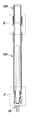
図1は、脊柱14の2つ以上の隣り合った椎骨12を互いに対する然るべき位置にそれを用いて安定させることのできる全体として参照符号10で表す脊柱安定化システムを概略的に示す。脊柱安定化システム10は、ボーンスクリュー又は椎弓根スクリュー18の形態の複数の固締要素16を含む。複数の固締要素16は、固締区域20及び保持区域22を有する。
FIG. 1 schematically illustrates a spinal stabilization system, generally designated by the
保持区域22は、接続要素26を収容するための接続要素受け24を有し、椎弓根スクリュー18のヘッド28上に形成される。ヘッド28はフォーク形であり、固締要素16の長手方向軸30に関して直径方向に対向する保持区域32を有する。保持区域32に雌ねじ34が設けられる。好ましくは固締区域20が、骨ねじ山36の設けられたシャフト38の形態である結果、固締要素16は椎骨12に特にその椎弓根にねじ込むことができる。別法として、固締区域20を骨鉤又は骨釘の形態にすることもできる。
The holding
任意で、固締区域20と保持区域22は、一体の構成とすることができ又は図に示す実施形態におけるように、互いに対して移動可能とすることができ、例えば固締区域20と保持区域22との間に形成される玉継手により規定される継手中心の周りで枢動可能とすることができる。従って、椎弓根スクリュー18は特に多軸スクリューの形態である。
Optionally, the clamping
例えば、図9Aに示す固定スクリュー44の形態の固定要素42が接続要素26を固定するように働く。接続要素26は、接続ロッド40又はプレート形要素の形態にすることができる。図9B及び図9Cに概略的に示すような接続位置において、固定スクリュー44は、接続要素26を押す及び/又は押下するために押下要素に接続又は連結される。換言すれば、固定要素42が押下要素46を担持するとも言える。押下要素46は、好ましくは回転可能であるように、但し軸方向に不動であるように、固定要素42上に装着される。
For example, a fixing
固定要素42及び押下要素46の構成を、以下で図9A〜図9Cと合わせてより詳細に説明する。
The configuration of the fixing
固定スクリュー44は、直径の低減された、ねじ山のないシャフト区域50が遠位側で接続された円筒形ヘッド48を有する。シャフト区域50に遠位側で接続されるのは、雄ねじ52である。雄ねじ52は、所定の折断点54を形成する凹部56により、近位雄ねじ区域58と遠位雄ねじ区域60とに分割される。凹部56は環状溝の形態であり、好ましくは楔形であり、固定要素42から離れる方を向いて開放している。この環状溝は、固定要素42を外側でリングの形態に包囲する。固定要素42は所定の折断点54により、遠位固定要素区域42と近位固定要素区域64とに分けられる。固定要素42は、全体として一体の構成であり、好ましくは生体適合性金属製、例えばチタン又はチタン合金製である。
The
固定要素は内部が中空であり、従って全体として略スリーブ形である。固定要素42の内径は、その内側で2つの段部になって低減される。ヘッド48の領域では、内径66aは、近位固定要素区域64のそのほかの部分における内径66bよりも幾分大きい。遠位固定要素区域62の領域における内径66cは、やはり内径66bよりも幾分小さい。遠位固定要素区域62は、遠位側では固定要素42の長手方向軸70に対して交差方向に底部68が延びることにより閉じている。
The fixing element is hollow inside and is therefore generally sleeve-shaped as a whole. The inner diameter of the fixing
近位方向を向いて開放している近位工具要素受け72が、ヘッド48の領域内に具体的には長手方向軸70と平行に整列してヘッド48の領域において、固定要素42の中空円筒形のスリーブ壁76内に部分的に形成される合計で6つの孔74により形成される。従って、要するに円みのある多数の内面78が形成されるのであり、この内面は対応するねじ込み具80と係合させることができる。
A proximal
遠位固定要素区域62の領域では、長手方向軸70と平行に整列してスリーブ壁76に部分的に係合する合計で6つの孔84を製作することにより、遠位固定要素区域62の内側に、基本的には同様に形成される遠位工具要素受け82が形成される。任意で図9Cに示す孔84は底部68を貫通し、従ってその貫通開口86を形成することもできる。従って、要するに遠位固定要素区域62も、遠位工具要素受け82を規定する、円みのある多数の内面88を有する。工具要素受け82は、図11Aに概略的に示すように相応に構成されたねじ込み具90と係合させることができる。
In the region of the distal
押下要素46は略スリーブ形であり、押下要素の近位端92でそれ自体閉じている保持リング94を有する。接続位置のとき、端部92は止め98を形成するヘッド48の遠位方向を向くリング形の止め面96に寄りかかる。保持リング94から遠位方向に延びているのは、接続位置のときにその遠位端102が遠位側で底部68を越えて突き出る、長手方向軸70に関して直径方向に対向する2つの押下突起100である。端部102は、遠位方向を向いて凹形に湾曲しているのであり、任意で要素26の曲率に適合させることができる。保持リング94の外径はヘッド48の外径に対応するため、接続位置のとき図9Bに概略的に示すような固定要素42と押下要素46とから成る完全な略円筒形の組立体が形成される。
The
押下突起100は、長手方向軸70に関して直径方向に対向する、凹部103を形成するスリット104により分離される。押下突起100の両脇に形成されるのは、周方向に突出して互いを向く案内突起106である。案内突起106は、遠位方向を又はほぼ遠位方向を向く、傾斜した摺動面108を規定する。案内突起106は保持リング94から幾分離間するのであり、周方向に開放している欠刻110が形成される。
The
押下突起100上に形成されるのは、押下要素46の内側114から突き出て長手方向軸70に向かう方向を向くロック突起112である。スリット104が存在しなかった場合には、2つのロック突起112は環状突起により形成されることになる。ロック突起112は押下突起100上で欠刻110の幾分遠位側の方へ配置される。ロック突起112は遠位方向を向いて傾いており、従って摺動面116をも有する。
Formed on the
押下要素46の外径が案内突起106の遠位側の方へ幾分僅かに増加するため、それぞれの端部102に向かって、僅かに円錐形の外面区域118が形成される。
Because the outer diameter of the
ねじ山のないシャフト区域50は、ロック突起112用にロック凹部120を形成するのであり、固定要素42と押下要素46との間には全体としてロック接続部122が形成される。接続位置のとき、押下要素46は保持リング94が雄ねじ52及びシャフト区域50を越えて押圧されてヘッド48に突き当たると、ロック突起112はロック凹部120内にロックする。
The unthreaded
押下要素46は、好ましくは蒸気滅菌可能なプラスチック材料から形成されるのであり、押下要素46と固定要素42とが合体される際、押下突起100は、長手方向軸70から幾分離れるように旋回し、ロック突起112がロック凹部120に侵入すると長手方向軸70に向かう方向に弾性的に戻るように再度旋回することができる。
The
以下で図1〜図11Bと合わせて、脊柱安定化システム10の埋込みを概略的に説明する。
The implantation of the spinal
第1ステップにおいて、固締要素16は所与の数で椎骨12にねじ込まれる。接続要素26を続いて固定要素42を保持区域22内に挿入できるようにするために、次のステップでは、案内スリーブ124が、知られているやり方で保持区域22にロックすることにより連結される。このことを、図4B及び図4Cに概略的に示す。
In the first step, the clamping
案内スリーブ124を固締要素16に連結した後、次のステップでは器具を案内するように働く内側スリーブ126が、近位側から案内スリーブ124内に導入される。内側スリーブ126は、その遠位端に遠位方向を向く4つのロッド形突起128を有する。4つのロッド形突起128は、保持区域22と案内スリーブ124の両方と係合させることができる。内側スリーブ126の案内スリーブ124内への導入を、図5A〜図7Dに概略的に示す。
After coupling the
上に記載した2つのステップの別法として、執刀医は、案内スリーブ124と、この案内スリーブ内に挿入される内側スリーブ126とから成るユニットを助手に渡させることもできる。執刀医は、これらのスリーブを保持区域22にロックすることにより連結する。
As an alternative to the two steps described above, the surgeon can hand the assistant a unit consisting of a
内側スリーブ126には、その遠位端から出発して長手方向軸30に関して直径方向に対向する窓様の2つの欠刻130が設けられる。従って、これらの欠刻130間には、これも長手方向軸30に関して正反対にあり遠位方向を向く2つの連結突起132が形成される。連結突起132には、雌ねじ34と同じ寸法の雌ねじ134が設けられる。雌ねじ34と雌ねじ134の両方は、雄ねじ52に対応するように形成される。
The
雌ねじ134に近位側で接しているのは、近位方向を向く止め面136である。止め面136の機能を以下で説明する。
Proximal to the
次のステップにおいて、図1に概略的に示すように、保持器具138の連結された接続要素26を、欠刻130を通して固締要素16の接続要素受け24内に導入することができる。
In the next step, the connected connecting
市場で入手可能な脊柱安定化システムとは異なり、ここでは、接続要素26を接続要素受け24内へ更なる器具を用いて押し込む必要はない。脊柱安定化システム10において、この機能は押下要素46を担持する固定要素42に引き継がれる。
Unlike spinal stabilization systems available on the market, where need not be pushed using a further
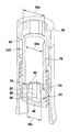
次のステップでは、図10Aに示すように固定要素42が、ねじ込み具80を用いて遠位方向へ内側スリーブ126の雌ねじ134にねじ付けられる。具体的には、図10Bに概略的に示すように保持リング94が止め面136に突き当たるまでである。ねじ込み具80は、近位工具要素受け72に係合する。押下突起100の端部102は、ねじ込み中に接続要素26と接触し、固定要素42を更にねじ込む間、この接続要素を接続要素受け24内に押し込む。図11Aの異なる断面斜視図から再度明白であるように、固定要素42は、押下要素46を用いて接続要素26を接続要素受け24内に保持する。保持リング94が止め面136に突き当たるこの組立て位置のときに、遠位固定要素区域62が、遠位側にて雌ねじ134を越えて突き出ること、従ってこの雌ねじと係合状態にないこともこの図から明らかである。
In the next step, as shown in FIG. 10A, the
押下要素46により保持される接続要素26を保持区域22上の接続要素受け24内に最終的に固定するために、ねじ込み具80が引き抜かれ、ねじ込み具90が導入され、ねじ込み具90の遠位端が遠位工具要素受け82と係合させられる。ねじ込みにより近位固定要素区域64が内側スリーブ126に連結されるおかげで、対応するトルクを加えることにより所定の折断点54を破壊し、近位固定要素区域64から遠位固定要素区域62を不可逆的に分離することができる。従って遠位固定要素区域62は自由になるため、この遠位固定要素区域を更に遠位方向に、近位固定要素区域64とは無関係に移動させて雌ねじ34と係合させ、底部68が接続要素26に突き当たるまで、従って接続要素26が最終的に接続要素受け24内で緊締状態に保持されるまで、この雌ねじ内にねじ込むことができる。
In order to finally secure the connecting
所与の接続要素26は全て、固定要素42を用いて記載したやり方で固締要素16の保持区域22上に固定される。
All the given connecting
最終的に、押下要素46が上に配置された近位固定要素区域64は、ねじ込み具80を用いて近位方向にねじを緩められ、案内スリーブ124から内側スリーブ126が近位方向に引き出され、案内スリーブ124は保持区域22から連結解除される。別法として、案内スリーブ124と内側スリーブ126とから成るユニットを、概して1つのステップにおいて除去することもできる。今や脊柱安定化システム10は、椎骨12に所望するように固定される。
Finally, the proximal
従って、特に記載した脊柱安定化システム10は、知られているシステムに設けられるような、保持区域22から近位方向に突き出る拡張部なしで済ますことができる。この拡張部がある場合、拡張部は固定要素42を保持区域22上に固定した後に、例えば折断により除去されねばならない。更に記載した脊柱安定化システム10において、例えば案内スリーブ124の外側の周りに係合する更なる押し下げスリーブの形態のロッド押し込み器具を設けることは余分なものとなる。ロッド押し込み器具を設けることは、脊柱安定化システム10を埋め込むための、低侵襲性のアクセス用の皮膚切開が幾分拡大されねばならないことになるという更なる欠点を有するであろう。提案される脊柱安定化システム10により、この欠点は排除される。
Thus, the specifically described
図12及び図13に、内側スリーブ126’及びこの内側スリーブ126’と相互作用する固定要素42’の代わりの実施形態を概略的に示す。内側スリーブ126’及び固定要素42’は、その構成及び機能において内側スリーブ126及び固定要素42にほぼ対応する。
12 and 13 schematically show an alternative embodiment of the inner sleeve 126 'and the securing element 42' that interacts with the inner sleeve 126 '. Inner sleeve 126 'and securing element 42' correspond approximately to
内側スリーブ126’と内側スリーブ126との間の差異は、基本的に雌ねじ134’が内側スリーブ126’上で、内側スリーブ126上の雌ねじ134よりも更に幾分近位方向に配置されるということである。従って雌ねじ134’は、内側スリーブ126’の内径が幾分広がっている領域内に配置される。従って雌ねじ134’は、図11Aに概略的に示すように、固定要素42が遠位方向で前方へ最大程度押圧されると、内側スリーブ126内では、雄ねじ52に対して外径の拡大したヘッドが配置される場所に配置される。これとは対照的に、雌ねじ134’は今や、ヘッド48’が正に着座するところに配置される。この雌ねじは、固定要素42’のヘッド48’上に形成される近位雄ねじ区域58’の雄ねじと相互作用する。従って固定要素42’は、互いから空間的に明らかに分離する2つの雄ねじ区域、具体的には遠位固定要素区域62’上の遠位雄ねじ区域60’と近位固定要素区域64’上の近位雄ねじ区域58’とを有する。従って近位雄ねじ区域58’と遠位雄ねじ区域60’はその直径も相違し、遠位雄ねじ区域60’の方が幾分小さい外径である。
The difference between the
内側スリーブ126’は、内側スリーブ126との更なる差異を有する。その近位端から出発して、内側スリーブ126’の内壁面140’に螺旋溝142’が形成される。固定要素42’の押下突起100’の対応する突起が、螺旋溝142’に係合する結果、固定要素42’を内側スリーブ126’内に挿入すると、押下突起100’はスリット形の欠刻130’に係合できるような仕方で整列する。
The
固定要素42’が機能する仕方は、基本的に固定要素42の機能に対応する。同様のやり方で、図10A、図10B,図11A、及び図11Bと合わせて記載したように、ねじ込み具80が近位固定要素受け72’に係合すると、固定要素42’が内側スリーブ126’の雌ねじ134’に遠位方向にねじ付けられる。具体的には、押下突起100’の遠位端102’が接続要素26に突き当たるまでである。固定要素42’が更にねじ込まれると、押下突起100’の端部102’は接続要素26を接続要素受け24内に押し込む。図13に概略的に示すように、固定要素42’は、押下要素46’を用いて接続要素26を接続要素受け24内に保持する。押下突起100’の遠位端102’が接続要素26に突き当たるこの組立て位置のときに、遠位固定要素区域62’が未だに雌ねじ34と係合状態にないこともこの図からはっきりと明白である。
The manner in which the fixing
押下要素46’により保持される接続要素26を保持区域22上の接続要素受け24内に最終的に固定するために、ねじ込み具80が引き抜かれ、ねじ込み具90が挿入され、ねじ込み具90の遠位端が遠位工具要素受け82’と係合させられる。ねじ込みにより近位固定要素区域64’が内側スリーブ126’に連結されるおかげで、対応するトルクを加えることにより所定の折断点54’を破壊し、近位固定要素区域64’から遠位固定要素区域62’を不可逆的に分離することができる。従って、遠位固定要素区域62’は自由になるため、この遠位固定要素区域を更に遠位方向に、近位固定要素区域64’とは無関係に移動させて雌ねじ34と係合させ、底部68’が接続要素26に突き当たるまで、従って接続要素26が最終的に接続要素受け24内で緊締状態に保持されるまで、この雌ねじ内にねじ込むことができる。
In order to finally fix the connecting
他の点では、脊柱安定化システム10は上述のような内側スリーブ126’及び固定要素42’でもって同様の仕方で機能する。
In other respects, the
任意でねじ込み具80及びねじ込み具90の機能を、特に、多部分構成とすることのできる単一の器具に合体させることもできる。
Optionally, the functions of the screwing
Claims (15)
前記外科用固締要素(16)が、固締区域(20)と、接続要素受け(24)を備えた保持区域(22)と、前記接続要素(26)を前記接続要素受け(24)内で固定するための、前記保持区域(22)上に固定可能な固定要素(42;42’)とを含む外科用固締要素において、
前記固定要素(42;42’)が、前記接続要素(26)を前記接続要素受け(24)内で押下するための押下要素(46;46’)を担持すること、
前記固定要素(42;42’)が、遠位固定要素区域(62;62’)と近位固定要素区域(64;64’)を分離する所定の折断点(54;54’)を有すること、及び
前記押下要素(46;46’)の少なくとも一部分が、前記近位固定要素区域(64;64’)上に配置されること、
を特徴とする外科用固締要素。 A surgical clamping element (16) for a spinal stabilization system (10) comprising at least two clamping elements (16) and at least one connecting element (26),
The surgical clamping element (16) includes a clamping area (20), a holding area (22) with a connecting element receiver (24), and the connecting element (26) in the connecting element receiver (24). A surgical fastening element comprising a securing element (42; 42 ') securable on the retaining area (22) for securing with
The securing element (42; 42 ') carries a pushing element (46; 46') for pushing the connecting element (26) in the connecting element receptacle (24);
Said anchoring element (42; 42 ') has a predetermined break point (54; 54') separating the distal anchoring element area (62; 62 ') and the proximal anchoring element area (64; 64') And at least a portion of the push element (46; 46 ') is disposed on the proximal anchoring element area (64; 64');
Surgical fastening element characterized by.
前記固定要素(42;42’)が、固定スクリュー(44;44’)の形態に構成され、前記固定スクリュー(44;44’)が、該固定スクリュー(44;44’)の遠位端から出発して近位方向に延びる雄ねじ(52;52’)を含むこと、及び
前記雄ねじ(52;52’)が、前記保持区域(22)上に形成された雌ねじ(34)に対応するように構成されること、
を特徴とする外科用固締要素。 The surgical fastening element according to claim 1 or 2,
Said fixing element (42; 42 ') is configured in the form of a fixing screw (44; 44'), said fixing screw (44; 44 ') from the distal end of said fixing screw (44; 44') Including a male screw (52; 52 ′) extending in a proximal direction starting from the male screw (52; 52 ′) so as to correspond to a female screw (34) formed on the holding area (22). Composed,
Surgical fastening element characterized by.
前記少なくとも2つの外科用固締要素(16)のうちの少なくとも1つが、固締区域(20)と、接続要素受け(24)を備えた保持区域(22)と、前記接続要素(26)を前記接続要素受け(24)内で固定するための、前記保持区域(22)上に固定可能な固定要素(42)とを含む脊柱安定化システムにおいて、
前記固定要素(42;42’)が、前記接続要素(26)を前記接続要素受け(24)内で押下するための押下要素(46;46’)を担持すること、
前記固定要素(42;42’)が、遠位固定要素区域(62;62’)と近位固定要素区域(64;64’)を分離する所定の折断点(54;54’)を有すること、及び
前記押下要素(46;46’)の少なくとも一部分が、前記近位固定要素区域(64;64’)上に配置されること、
を特徴とする脊柱安定化システム。 A spinal stabilization system (10) comprising at least two surgical clamping elements (16) and at least one connecting element (26),
At least one of the at least two surgical clamping elements (16) includes a clamping area (20), a holding area (22) with a connecting element receiver (24), and the connecting element (26). A spinal stabilization system comprising a securing element (42) securable on the retaining area (22) for securing within the connecting element receiver (24);
The securing element (42; 42 ') carries a pushing element (46; 46') for pushing the connecting element (26) in the connecting element receptacle (24);
Said anchoring element (42; 42 ') has a predetermined break point (54; 54') separating the distal anchoring element area (62; 62 ') and the proximal anchoring element area (64; 64') And at least a portion of the push element (46; 46 ') is disposed on the proximal anchoring element area (64; 64');
Spinal column stabilization system characterized by.
Applications Claiming Priority (5)
| Application Number | Priority Date | Filing Date | Title |
|---|---|---|---|
| DE102013102976 | 2013-03-22 | ||
| DE102013102976.0 | 2013-03-22 | ||
| DE102013107498.7A DE102013107498A1 (en) | 2013-03-22 | 2013-07-15 | Spine stabilization system and surgical fastener for a spine stabilization system |
| DE102013107498.7 | 2013-07-15 | ||
| PCT/EP2014/055468 WO2014147104A1 (en) | 2013-03-22 | 2014-03-19 | Vertebral column-stabilizing system and surgical fastening element for a vertebral column-stabilizing system |
Publications (3)
| Publication Number | Publication Date |
|---|---|
| JP2016514506A JP2016514506A (en) | 2016-05-23 |
| JP2016514506A5 JP2016514506A5 (en) | 2017-04-20 |
| JP6556117B2 true JP6556117B2 (en) | 2019-08-07 |
Family
ID=51484596
Family Applications (1)
| Application Number | Title | Priority Date | Filing Date |
|---|---|---|---|
| JP2016503645A Active JP6556117B2 (en) | 2013-03-22 | 2014-03-19 | Spine stabilization system and surgical fastening element for spinal stabilization system |
Country Status (5)
| Country | Link |
|---|---|
| US (1) | US9655653B2 (en) |
| EP (1) | EP2976031B1 (en) |
| JP (1) | JP6556117B2 (en) |
| DE (1) | DE102013107498A1 (en) |
| WO (1) | WO2014147104A1 (en) |
Families Citing this family (15)
| Publication number | Priority date | Publication date | Assignee | Title |
|---|---|---|---|---|
| EP2996591B1 (en) * | 2013-05-13 | 2020-11-04 | Neo Medical SA | Orthopedic implant kit |
| EP3288473B1 (en) * | 2015-04-30 | 2022-12-28 | K2M, Inc. | Rod reducer |
| CN104905872B (en) * | 2015-05-12 | 2017-05-31 | 山东威高骨科材料股份有限公司 | A kind of breast-stroke clamps binding clip |
| EP3106110B1 (en) * | 2015-06-16 | 2017-10-11 | Biedermann Technologies GmbH & Co. KG | Extension device for a bone anchor |
| JP2017038871A (en) * | 2015-08-21 | 2017-02-23 | 賢 石井 | Spinal implant surgical instrument |
| US9439692B1 (en) * | 2015-10-09 | 2016-09-13 | Spine Wave, Inc. | Minimally invasive spinal fixation system and method therefor |
| EP3287088B1 (en) | 2016-08-24 | 2019-01-09 | Biedermann Technologies GmbH & Co. KG | Instrument for locking and unlocking a head of a bone anchor in a polyaxial bone anchoring device |
| EP3441028B1 (en) * | 2017-08-08 | 2021-10-06 | Biedermann Technologies GmbH & Co. KG | Receiving part and instrument for holding the receiving part |
| US10610269B2 (en) * | 2017-09-05 | 2020-04-07 | Medos International Sarl | Modular surgical instruments and related methods |
| TWI649064B (en) * | 2017-09-07 | 2019-02-01 | 台灣微創醫療器材股份有限公司 | Device for surgery of stabilizing bone segments and extending assembly thereof |
| US10959859B2 (en) | 2018-07-25 | 2021-03-30 | Warsaw Orthopedic, Inc. | Spinal implant system and method |
| US10799300B2 (en) * | 2018-10-18 | 2020-10-13 | Warsaw Orthopedic, Inc. | Spinal implant system and method |
| IT201900005358A1 (en) * | 2019-04-08 | 2020-10-08 | Medacta Int Sa | POLYAXIAL SURGICAL SCREW AND DEVICE FOR THE IMPLANTATION OF SAID SURGICAL SCREW |
| US11134994B2 (en) * | 2020-01-30 | 2021-10-05 | Warsaw Orthopedic, Inc. | Spinal-correction system having threaded extender tabs and reduction tab extenders |
| DE102022120383A1 (en) * | 2021-08-13 | 2023-02-16 | Zimmer Biomet Spine, Inc. | REDUCING PIECE FOR A STABILIZATION ELEMENT IN SPINE SURGERY |
Family Cites Families (19)
| Publication number | Priority date | Publication date | Assignee | Title |
|---|---|---|---|---|
| FR2624720B1 (en) * | 1987-12-21 | 1994-04-15 | Fabrication Materiel Orthopediqu | IMPLANT FOR OSTEOSYNTHESIS DEVICE, ESPECIALLY OF THE RACHIS |
| DE9403231U1 (en) * | 1994-02-26 | 1994-04-21 | Aesculap Ag | Surgical implant |
| FR2729291B1 (en) * | 1995-01-12 | 1997-09-19 | Euros Sa | RACHIDIAN IMPLANT |
| DE29606468U1 (en) | 1996-04-09 | 1997-08-07 | Link Waldemar Gmbh Co | Spinal fixator |
| US5667508A (en) * | 1996-05-01 | 1997-09-16 | Fastenetix, Llc | Unitary locking cap for use with a pedicle screw |
| US6280445B1 (en) * | 1999-04-16 | 2001-08-28 | Sdgi Holdings, Inc. | Multi-axial bone anchor system |
| US6530929B1 (en) * | 1999-10-20 | 2003-03-11 | Sdgi Holdings, Inc. | Instruments for stabilization of bony structures |
| US6440132B1 (en) * | 2000-05-24 | 2002-08-27 | Roger P. Jackson | Open head bone screw closure with threaded boss |
| FR2829014B1 (en) | 2001-09-03 | 2005-04-08 | Stryker Spine | SPINAL OSTEOSYNTHESIS SYSTEM COMPRISING A SUPPORT SKATE |
| US7842073B2 (en) * | 2002-04-18 | 2010-11-30 | Aesculap Ii, Inc. | Screw and rod fixation assembly and device |
| US6730089B2 (en) * | 2002-08-26 | 2004-05-04 | Roger P. Jackson | Nested closure plug and set screw with break-off heads |
| US20060095035A1 (en) * | 2004-11-03 | 2006-05-04 | Jones Robert J | Instruments and methods for reduction of vertebral bodies |
| US7776067B2 (en) * | 2005-05-27 | 2010-08-17 | Jackson Roger P | Polyaxial bone screw with shank articulation pressure insert and method |
| EP1891904B1 (en) * | 2006-08-24 | 2013-12-25 | Biedermann Technologies GmbH & Co. KG | Bone anchoring device |
| ES2359477T3 (en) * | 2007-07-20 | 2011-05-24 | Synthes Gmbh | POLIAXIAL ELEMENT FOR BONE FIXATION. |
| DE102007042953B4 (en) * | 2007-08-30 | 2015-01-22 | Aesculap Ag | Orthopedic retention system |
| WO2009117724A2 (en) * | 2008-03-21 | 2009-09-24 | Life Spine, Inc. | Spinal rod guide for a vertebral screw spinal rod connector assembly |
| ES2392381T3 (en) * | 2008-04-22 | 2012-12-10 | Synthes Gmbh | Bone fixation element with reduction tabs |
| DE102009032034A1 (en) | 2009-06-26 | 2010-12-30 | Aesculap Ag | Surgical bone anchoring device and spine fixation system |
-
2013
- 2013-07-15 DE DE102013107498.7A patent/DE102013107498A1/en not_active Withdrawn
-
2014
- 2014-03-19 JP JP2016503645A patent/JP6556117B2/en active Active
- 2014-03-19 EP EP14711960.6A patent/EP2976031B1/en active Active
- 2014-03-19 WO PCT/EP2014/055468 patent/WO2014147104A1/en active Application Filing
-
2015
- 2015-08-17 US US14/827,479 patent/US9655653B2/en active Active
Also Published As
| Publication number | Publication date |
|---|---|
| US20150351810A1 (en) | 2015-12-10 |
| WO2014147104A1 (en) | 2014-09-25 |
| DE102013107498A1 (en) | 2014-09-25 |
| EP2976031A1 (en) | 2016-01-27 |
| EP2976031B1 (en) | 2018-09-12 |
| US9655653B2 (en) | 2017-05-23 |
| JP2016514506A (en) | 2016-05-23 |
Similar Documents
| Publication | Publication Date | Title |
|---|---|---|
| JP6556117B2 (en) | Spine stabilization system and surgical fastening element for spinal stabilization system | |
| US20210338287A1 (en) | Coupling assembly for coupling a rod to a bone anchoring element, polyaxial bone anchoring device and modular stabilization device | |
| US9510874B2 (en) | Medical instrument for holding and handling a surgical securing element, and vertebral column stabilization system | |
| US9492209B2 (en) | Extension device for a bone anchor, in particular for minimally invasive surgery | |
| US7226453B2 (en) | Instrument for inserting, adjusting and removing pedicle screws and other orthopedic implants | |
| EP2764840B1 (en) | Coupling assembly for coupling a rod to a bone anchoring element and bone anchoring device with such a coupling assembly | |
| EP2301458B1 (en) | Bone anchoring device | |
| EP2957246B1 (en) | Extension device for a bone anchor, in particular for minimally invasive surgery | |
| US9901378B2 (en) | Surgical instrumentation for spinal surgery | |
| EP3013266B1 (en) | Orthopedic anchor assembly | |
| JP6580517B2 (en) | Instruments used with bone fixation devices in spinal surgery, and systems for bone fixation devices | |
| EP2221013A1 (en) | Receiving part for receiving a rod for coupling the rod to a bone anchoring element and a bone anchoring device with such a receiving part | |
| JP2016514506A5 (en) | ||
| EP2765937B1 (en) | Orthopedic anchor assembly | |
| CN106137369B (en) | Bone nail and percutaneous minimally invasive pedicle fixing system | |
| EP3536271B1 (en) | Polyaxial bone anchoring device and system of an instrument and a polyaxial bone anchoring device | |
| EP3838197B1 (en) | Instrument for use with a bone anchoring device | |
| CN114052879A (en) | Bone anchoring device | |
| US20220125483A1 (en) | Coupling device for coupling a rod to a bone anchor |
Legal Events
| Date | Code | Title | Description |
|---|---|---|---|
| A521 | Request for written amendment filed |
Free format text: JAPANESE INTERMEDIATE CODE: A523 Effective date: 20170317 |
|
| A621 | Written request for application examination |
Free format text: JAPANESE INTERMEDIATE CODE: A621 Effective date: 20170317 |
|
| A977 | Report on retrieval |
Free format text: JAPANESE INTERMEDIATE CODE: A971007 Effective date: 20180226 |
|
| A131 | Notification of reasons for refusal |
Free format text: JAPANESE INTERMEDIATE CODE: A131 Effective date: 20180306 |
|
| A601 | Written request for extension of time |
Free format text: JAPANESE INTERMEDIATE CODE: A601 Effective date: 20180604 |
|
| A521 | Request for written amendment filed |
Free format text: JAPANESE INTERMEDIATE CODE: A523 Effective date: 20180731 |
|
| A131 | Notification of reasons for refusal |
Free format text: JAPANESE INTERMEDIATE CODE: A131 Effective date: 20181002 |
|
| A601 | Written request for extension of time |
Free format text: JAPANESE INTERMEDIATE CODE: A601 Effective date: 20181227 |
|
| A521 | Request for written amendment filed |
Free format text: JAPANESE INTERMEDIATE CODE: A523 Effective date: 20190228 |
|
| TRDD | Decision of grant or rejection written | ||
| A01 | Written decision to grant a patent or to grant a registration (utility model) |
Free format text: JAPANESE INTERMEDIATE CODE: A01 Effective date: 20190618 |
|
| A61 | First payment of annual fees (during grant procedure) |
Free format text: JAPANESE INTERMEDIATE CODE: A61 Effective date: 20190709 |
|
| R150 | Certificate of patent or registration of utility model |
Ref document number: 6556117 Country of ref document: JP Free format text: JAPANESE INTERMEDIATE CODE: R150 |
|
| R250 | Receipt of annual fees |
Free format text: JAPANESE INTERMEDIATE CODE: R250 |
|
| R250 | Receipt of annual fees |
Free format text: JAPANESE INTERMEDIATE CODE: R250 |