EP3287088B1 - Instrument for locking and unlocking a head of a bone anchor in a polyaxial bone anchoring device - Google Patents
Instrument for locking and unlocking a head of a bone anchor in a polyaxial bone anchoring device Download PDFInfo
- Publication number
- EP3287088B1 EP3287088B1 EP16185546.5A EP16185546A EP3287088B1 EP 3287088 B1 EP3287088 B1 EP 3287088B1 EP 16185546 A EP16185546 A EP 16185546A EP 3287088 B1 EP3287088 B1 EP 3287088B1
- Authority
- EP
- European Patent Office
- Prior art keywords
- instrument
- tube
- actuator assembly
- head
- bone anchoring
- Prior art date
- Legal status (The legal status is an assumption and is not a legal conclusion. Google has not performed a legal analysis and makes no representation as to the accuracy of the status listed.)
- Active
Links
- 210000000988 bone and bone Anatomy 0.000 title claims description 80
- 238000004873 anchoring Methods 0.000 title claims description 68
- 230000033001 locomotion Effects 0.000 claims description 8
- 230000000712 assembly Effects 0.000 description 6
- 238000000429 assembly Methods 0.000 description 6
- 238000001356 surgical procedure Methods 0.000 description 6
- 239000000463 material Substances 0.000 description 3
- 230000004323 axial length Effects 0.000 description 2
- 238000004140 cleaning Methods 0.000 description 2
- 238000012937 correction Methods 0.000 description 2
- 238000003780 insertion Methods 0.000 description 2
- 230000037431 insertion Effects 0.000 description 2
- 238000012546 transfer Methods 0.000 description 2
- 229910001200 Ferrotitanium Inorganic materials 0.000 description 1
- 206010042618 Surgical procedure repeated Diseases 0.000 description 1
- RTAQQCXQSZGOHL-UHFFFAOYSA-N Titanium Chemical compound [Ti] RTAQQCXQSZGOHL-UHFFFAOYSA-N 0.000 description 1
- 230000008878 coupling Effects 0.000 description 1
- 238000010168 coupling process Methods 0.000 description 1
- 238000005859 coupling reaction Methods 0.000 description 1
- 230000001419 dependent effect Effects 0.000 description 1
- 238000011161 development Methods 0.000 description 1
- 230000018109 developmental process Effects 0.000 description 1
- 238000006073 displacement reaction Methods 0.000 description 1
- 230000000694 effects Effects 0.000 description 1
- 238000012986 modification Methods 0.000 description 1
- 230000004048 modification Effects 0.000 description 1
- 229910001220 stainless steel Inorganic materials 0.000 description 1
- 239000010935 stainless steel Substances 0.000 description 1
- 239000010936 titanium Substances 0.000 description 1
Images


Classifications
-
- A—HUMAN NECESSITIES
- A61—MEDICAL OR VETERINARY SCIENCE; HYGIENE
- A61B—DIAGNOSIS; SURGERY; IDENTIFICATION
- A61B17/00—Surgical instruments, devices or methods, e.g. tourniquets
- A61B17/56—Surgical instruments or methods for treatment of bones or joints; Devices specially adapted therefor
- A61B17/58—Surgical instruments or methods for treatment of bones or joints; Devices specially adapted therefor for osteosynthesis, e.g. bone plates, screws, setting implements or the like
- A61B17/68—Internal fixation devices, including fasteners and spinal fixators, even if a part thereof projects from the skin
- A61B17/70—Spinal positioners or stabilisers ; Bone stabilisers comprising fluid filler in an implant
- A61B17/7074—Tools specially adapted for spinal fixation operations other than for bone removal or filler handling
- A61B17/7083—Tools for guidance or insertion of tethers, rod-to-anchor connectors, rod-to-rod connectors, or longitudinal elements
-
- A—HUMAN NECESSITIES
- A61—MEDICAL OR VETERINARY SCIENCE; HYGIENE
- A61B—DIAGNOSIS; SURGERY; IDENTIFICATION
- A61B17/00—Surgical instruments, devices or methods, e.g. tourniquets
- A61B17/56—Surgical instruments or methods for treatment of bones or joints; Devices specially adapted therefor
- A61B17/58—Surgical instruments or methods for treatment of bones or joints; Devices specially adapted therefor for osteosynthesis, e.g. bone plates, screws, setting implements or the like
- A61B17/88—Osteosynthesis instruments; Methods or means for implanting or extracting internal or external fixation devices
- A61B17/92—Impactors or extractors, e.g. for removing intramedullary devices
-
- A—HUMAN NECESSITIES
- A61—MEDICAL OR VETERINARY SCIENCE; HYGIENE
- A61B—DIAGNOSIS; SURGERY; IDENTIFICATION
- A61B17/00—Surgical instruments, devices or methods, e.g. tourniquets
- A61B17/56—Surgical instruments or methods for treatment of bones or joints; Devices specially adapted therefor
- A61B17/58—Surgical instruments or methods for treatment of bones or joints; Devices specially adapted therefor for osteosynthesis, e.g. bone plates, screws, setting implements or the like
- A61B17/68—Internal fixation devices, including fasteners and spinal fixators, even if a part thereof projects from the skin
- A61B17/70—Spinal positioners or stabilisers ; Bone stabilisers comprising fluid filler in an implant
- A61B17/7001—Screws or hooks combined with longitudinal elements which do not contact vertebrae
- A61B17/7032—Screws or hooks with U-shaped head or back through which longitudinal rods pass
-
- A—HUMAN NECESSITIES
- A61—MEDICAL OR VETERINARY SCIENCE; HYGIENE
- A61B—DIAGNOSIS; SURGERY; IDENTIFICATION
- A61B17/00—Surgical instruments, devices or methods, e.g. tourniquets
- A61B17/56—Surgical instruments or methods for treatment of bones or joints; Devices specially adapted therefor
- A61B17/58—Surgical instruments or methods for treatment of bones or joints; Devices specially adapted therefor for osteosynthesis, e.g. bone plates, screws, setting implements or the like
- A61B17/68—Internal fixation devices, including fasteners and spinal fixators, even if a part thereof projects from the skin
- A61B17/70—Spinal positioners or stabilisers ; Bone stabilisers comprising fluid filler in an implant
- A61B17/7001—Screws or hooks combined with longitudinal elements which do not contact vertebrae
- A61B17/7035—Screws or hooks, wherein a rod-clamping part and a bone-anchoring part can pivot relative to each other
- A61B17/7037—Screws or hooks, wherein a rod-clamping part and a bone-anchoring part can pivot relative to each other wherein pivoting is blocked when the rod is clamped
-
- A—HUMAN NECESSITIES
- A61—MEDICAL OR VETERINARY SCIENCE; HYGIENE
- A61B—DIAGNOSIS; SURGERY; IDENTIFICATION
- A61B17/00—Surgical instruments, devices or methods, e.g. tourniquets
- A61B17/56—Surgical instruments or methods for treatment of bones or joints; Devices specially adapted therefor
- A61B17/58—Surgical instruments or methods for treatment of bones or joints; Devices specially adapted therefor for osteosynthesis, e.g. bone plates, screws, setting implements or the like
- A61B17/68—Internal fixation devices, including fasteners and spinal fixators, even if a part thereof projects from the skin
- A61B17/70—Spinal positioners or stabilisers ; Bone stabilisers comprising fluid filler in an implant
- A61B17/7074—Tools specially adapted for spinal fixation operations other than for bone removal or filler handling
- A61B17/7076—Tools specially adapted for spinal fixation operations other than for bone removal or filler handling for driving, positioning or assembling spinal clamps or bone anchors specially adapted for spinal fixation
- A61B17/7077—Tools specially adapted for spinal fixation operations other than for bone removal or filler handling for driving, positioning or assembling spinal clamps or bone anchors specially adapted for spinal fixation for moving bone anchors attached to vertebrae, thereby displacing the vertebrae
- A61B17/7079—Tools requiring anchors to be already mounted on an implanted longitudinal or transverse element, e.g. where said element guides the anchor motion
-
- A—HUMAN NECESSITIES
- A61—MEDICAL OR VETERINARY SCIENCE; HYGIENE
- A61B—DIAGNOSIS; SURGERY; IDENTIFICATION
- A61B17/00—Surgical instruments, devices or methods, e.g. tourniquets
- A61B17/56—Surgical instruments or methods for treatment of bones or joints; Devices specially adapted therefor
- A61B17/58—Surgical instruments or methods for treatment of bones or joints; Devices specially adapted therefor for osteosynthesis, e.g. bone plates, screws, setting implements or the like
- A61B17/68—Internal fixation devices, including fasteners and spinal fixators, even if a part thereof projects from the skin
- A61B17/70—Spinal positioners or stabilisers ; Bone stabilisers comprising fluid filler in an implant
- A61B17/7074—Tools specially adapted for spinal fixation operations other than for bone removal or filler handling
- A61B17/7076—Tools specially adapted for spinal fixation operations other than for bone removal or filler handling for driving, positioning or assembling spinal clamps or bone anchors specially adapted for spinal fixation
- A61B17/7077—Tools specially adapted for spinal fixation operations other than for bone removal or filler handling for driving, positioning or assembling spinal clamps or bone anchors specially adapted for spinal fixation for moving bone anchors attached to vertebrae, thereby displacing the vertebrae
- A61B17/708—Tools specially adapted for spinal fixation operations other than for bone removal or filler handling for driving, positioning or assembling spinal clamps or bone anchors specially adapted for spinal fixation for moving bone anchors attached to vertebrae, thereby displacing the vertebrae with tubular extensions coaxially mounted on the bone anchors
-
- A—HUMAN NECESSITIES
- A61—MEDICAL OR VETERINARY SCIENCE; HYGIENE
- A61B—DIAGNOSIS; SURGERY; IDENTIFICATION
- A61B17/00—Surgical instruments, devices or methods, e.g. tourniquets
- A61B17/56—Surgical instruments or methods for treatment of bones or joints; Devices specially adapted therefor
- A61B17/58—Surgical instruments or methods for treatment of bones or joints; Devices specially adapted therefor for osteosynthesis, e.g. bone plates, screws, setting implements or the like
- A61B17/68—Internal fixation devices, including fasteners and spinal fixators, even if a part thereof projects from the skin
- A61B17/70—Spinal positioners or stabilisers ; Bone stabilisers comprising fluid filler in an implant
- A61B17/7074—Tools specially adapted for spinal fixation operations other than for bone removal or filler handling
- A61B17/7076—Tools specially adapted for spinal fixation operations other than for bone removal or filler handling for driving, positioning or assembling spinal clamps or bone anchors specially adapted for spinal fixation
- A61B17/7082—Tools specially adapted for spinal fixation operations other than for bone removal or filler handling for driving, positioning or assembling spinal clamps or bone anchors specially adapted for spinal fixation for driving, i.e. rotating, screws or screw parts specially adapted for spinal fixation, e.g. for driving polyaxial or tulip-headed screws
-
- A—HUMAN NECESSITIES
- A61—MEDICAL OR VETERINARY SCIENCE; HYGIENE
- A61B—DIAGNOSIS; SURGERY; IDENTIFICATION
- A61B17/00—Surgical instruments, devices or methods, e.g. tourniquets
- A61B17/56—Surgical instruments or methods for treatment of bones or joints; Devices specially adapted therefor
- A61B2017/564—Methods for bone or joint treatment
Definitions
- the invention relates to an instrument for locking and unlocking a head of a bone anchor in a polyaxial bone anchoring device.
- the instrument comprises a tube assembly with an inner tube and an outer tube that are displaceable relative to each other for independently locking and unlocking the head and an actuator assembly for actuating the tube assembly.
- Such an instrument is particularly applicable to a polyaxial bone anchoring device that has a receiving part with a head receiving portion for receiving the head of the bone anchor and an outer locking ring for locking the head.
- US 2013/0085536 A1 describes a polyaxial bone anchoring device including a receiving part with a rod receiving portion and head receiving portion for introducing and clamping of the head and a locking ring configured to be arranged around the head receiving portion.
- the locking ring includes an engagement structure for engagement with a tool to allow the locking ring to be moved out of the locking position, i.e. releasing the locking mechanism.
- the tool comprises a tubular member that is configured to engage the locking ring and a shaft acting on the receiving part. In one embodiment, unlocking of the head may be carried out while the rod is inserted.
- US 2013/0110179 A1 describes a set comprising a locking device and a separate unlocking device for locking and unlocking a multi-planar, taper lock screw.
- US 2014/0236236 A1 discloses a helping means for a polyaxial pedicle screw which basically consists of a plunger, which can be brought into engagement with an inlay (power transfer member) inserted in a receiving sleeve of the pedicle screw, and a tension sleeve which can be brought into engagement with the receiving sleeve.
- a coupling or shaft nut may be screwed onto an external thread of the tension sleeve, such that when the shaft nut is rotated on the tension sleeve, radially projecting drive pins provided at the plunger are driven by the shaft and a relative movement is created between the plunger and the tension sleeve.
- US 2013/0085536 A1 discloses a tool cooperating with a bone anchoring device.
- the tool has includes a tubular member and shaft which has a rear end with a handle.
- the shaft has an outer thread portion at a distance from the handle that cooperates with an internal thread portion of the tubular member.
- a stop limits an insertion depth of the shaft in the tubular member. An insertion depth can be adjusted by the cooperation of the two threads.
- US 2005/0131408 A1 discloses a percutaneous access device arranged to engage a receiving member of a of a bone anchor assembly and which includes an inner tube and an outer tube disposed about at least a portion of the inner tube.
- An adjustment mechanism in the form of a hollow tubular cap allows an operator to adjust the relative longitudinal position of the inner and outer tubes.
- the cap has internal threads that engage external threads provided on a proximal end of the outer tube. The threads allow the cap to be longitudinally adjusted relative to the outer tube.
- the inner tube is connected to the cap and thus moves with the cap.
- a temporary locking of the bone anchoring element in the receiving part can be effected using only the instrument with the rod already inserted into the receiving part but without the aid of a locking element such a set screw.
- the polyaxial bone anchoring device allows to adjust or re-adjust an angular position of the receiving part relative to the bone anchoring device several times while the rod is already inserted.
- the temporary locking of the head using the instrument also permits to use the polyaxial bone anchoring device like a monoaxial bone anchoring device.
- the receiving part of the polyaxial bone anchoring device may comprise extended tabs that allow the rod during the adjustment step to be on a position higher above the head compared to a receiving part without extended tabs.
- the instrument can be easily switched between an unlocking configuration in which the instrument allows pivoting of the head in the receiving part and a locking configuration in which the instruments effects a locking of the head in the receiving part and vice-versa.
- the switching can be effected by rotating the actuator assembly.
- An actuating mechanism of the actuator assembly of the instrument is designed such that the locking and unlocking of the head can be effected by the same grasping movement of a user.
- the actuator assembly may be removably connectable to the tube assembly, Thereby it is possible to adjust a plurality of polyaxial bone anchoring devices that each are connected to a tube assembly with one single actuator assembly one after the other. As the tube assemblies may be positioned close to each other, operating with one single actuator assembly is convenient in view of the reduced available space.
- the tube assemblies may be all the same or differ with respect to their length or other features such as the engagement features for engagement with the polyaxial bone anchoring device.
- the instrument may also provide a modular system that includes an actuator assembly and different tube assemblies that are adapted to be used with the actuator assembly.
- the instrument may additionally produce a tactile or audible sign when it enters one of the different configurations of locking, unlocking or removing. This further increases the safety and user-friendliness.
- the instrument comprises a tube assembly 20 and an actuator assembly 40 that is removably connectable to the tube assembly 20.
- the tube assembly 20 is connectable to a polyaxial bone anchoring device 10.
- the tube assembly 20 includes an outer tube 21 and an inner tube 31 and a longitudinal axis or tube axis L.
- the outer tube 21 and the inner tube 31 are in the assembled state axially displaceable relative to each other along the longitudinal axis L to a certain extent that permits to move a portion of the polyaxial bone anchoring device from an unlocking position of a bone anchor to a locking position of a bone anchor and vice-versa.
- the displacement of the inner tube 31 and the outer tube 21 relative to each other is effected by the actuator assembly 40 as explained below.
- the outer tube 21 comprises a front end 21a and a rear end 21b opposite to the front end 21 a.
- a front portion of the instrument adjacent to the front end 21a may taper in a section 22 towards the front end 21a to reduce an overall space needed by the instrument when attached to the polyaxial bone anchoring device 10.
- a recess 24 is formed that extends from the front end 21a of the outer tube 21 to a distance thereof.
- the recess 24 has a width in the circumferential direction that is larger than an upper width of the polyaxial bone anchoring device 10 and a height that permits a rod 6 as shown in Fig. 1 to extend therethrough and to be movable in an axial direction within the recess 24 ( Fig. 1 ).
- an engagement portion 25 that is adapted to engage a corresponding engagement portion of the polyaxial bone anchoring device 10 is provided.
- the engagement portion 25 may be in the form of a circumferentially extending rib that cooperates with a corresponding groove at the polyaxial bone anchoring device 10.
- a stepped portion or circumferentially extending shoulder 26 is provided that forms an abutment for the inner tube 31.
- a cut-out or recess 27 is formed on each side of the longitudinal axis L wherein the recess 27 extends to a distance from the rear end 21b.
- Each recess 27 has in a perspective view, seen in Figs. 7a and 7b , a substantially step-like shape forming a first recess area 27a that is open to the rear end 21b and adjacent thereto in a circumferential direction a second recess area 27b that has a smaller width and extends from a distance from the rear end 21b farther down, i.e. towards the front end 21a compared to the first recess area 27a.
- the recess 27 has the function to accommodate driving portions of the actuator assembly and driven portions from the inner tube 31 therein.
- the orientation of the recess 27 is such that the recess 27 is substantially aligned with the engagement portion 25 at the front end 21a.
- an elongate hole 28 is provided in the outer tube 21 wherein the longer axis of the elongate hole 28 is coaxial to the longitudinal axis L.
- the elongate hole 28 is located at a circumferential position slightly offset from the middle of the recess 24 at the front end 21a. Through the elongate hole 28 a pin connected to a stopper member may pass to enable a limited motion of the stopper member.
- longitudinally extending substantially parallel grooves 29a, 29b, 29c are provided in the outer surface the outer tube 21.
- the grooves 29a, 29b, 29c serve for receiving a pin of the actuator assembly to provide a tactile and/or audible sign when the actuator assembly assumes different rotational positions corresponding to locking and unlocking of the head or removal of the actuator assembly.
- the middle groove 29a may extend up to the rear end 21b.
- coaxially extending position markings 200a, 200b, 200c are provided at an outer surface of the outer tube 21.
- the position markings 200a, 200b, 200c are at a circumferential position of approximately that of the engagement portions of the outer tube 21 and serve for indicating in cooperation with a marking on the actuator assembly 40 to indicate an actuating position of locking or unlocking (markings 200c, 200b, respectively) or removing (marking 200a) of the actuator assembly 40.
- the middle marking 200a indicating the removing position may be longer than the other markings.
- the inner tube 31 comprises a front end 31a and a rear end 31b.
- An inner diameter of the inner tube 31 is such that a fixation element such as a set screw or a further instrument can pass through.
- a recess 34 is formed that substantially corresponds to the recess 24 of the outer tube 21, such that when the inner tube 31 is in the outer tube 21 the recesses 24 and 34 are aligned.
- an engagement structure 35 is provided that is configured to cooperate with a corresponding engagement structure at the polyaxial bone anchoring device.
- the engagement structure 35 in the embodiment shown is a circumferentially extending groove that may cooperate with a circumferentially extending rib at the polyaxial bone anchoring device.
- a further recess or cut-out 36 extends deeper into the inner tube 31 in an axial direction.
- the cut-out 36 serves for accommodating an end portion of a stopper member 300 explained below.
- a recessed surface portion 37 is provided in the outer surface of the inner tube 31.
- the recessed surface portion 37 is elongated in an axial direction and formed and sized so as to receive and guide the stopper member 300 therein.
- the recessed surface portion 37 may also have a widened end portion 37a in a direction towards the rear end 31b. At around or slightly above the widened end portion 37a a circumferentially extending outer narrow shoulder 37b is provided that forms an abutment for the stopper member 300. Spaced apart from the shoulder 37b is an annular protrusion 38 that serves for axially supporting a spring element 30, for example a coil spring, that acts onto the stopper member 300.
- first protrusions 39a, 39b are formed that serve as driven portions that are driven by driving portions of the actuator assembly 40 to displace the inner tube 31 relative to the outer tube 21.
- Two sets of first protrusions 39a, 39b are provided at opposite sides from the longitudinal axis L. As depicted in Figs. 3, 4 and 7a, 7b , one protrusion 39a is located at a first distance from the rear end 31b and the other protrusion 39b is provided at a second distance greater than the first distance from the rear end 31b and is circumferentially offset from the protrusion 39a.
- the protrusions 39a, 39b may have approximately a square-shaped contour and may have such a height that they are substantially flush with the outer cylindrical surface of the outer tube 21 when the inner tube 31 and the outer tube 21 are assembled. As depicted more in detail in Figs. 7a and 7b , in the assembled state, the protrusion 39a that is closer to the rear end 31a of the inner tube 31 is located in the first recess area 27a of the recess 27 of the outer tube and the second protrusion 39b is located in the lowermost portion of the recess area 27b of the recess 27 of the outer tube 21.
- the distance of the protrusions 39a, 39b in the circumferential direction is such that there is in the assembled state a gap G between the first protrusion 39a and an opposing sidewall of the recess 27 that serves for entering driving portions of the actuator assembly into the recess 27.
- the inner tube 31 may be assembled with the outer tube 21 by first introducing the lower protrusion 39b into the recess 27, rotating the inner tube 31 relative to the outer tube 21 and then entering the first protrusion 39a into the recess 27.
- the stopper member 300 may be provided to inhibit rotation of the tube assembly 20 relative to the polyaxial bone anchoring device 10 into a position where it can be disengaged from the polyaxial bone anchoring device 10.
- the stopper member 300 includes a shaft portion 301 and a base portion 302 that encompasses the inner tube 31 approximately in a mid-portion thereof.
- the shaft portion 301 is received and guided in the recessed surface portion 37 of the inner tube 31.
- a free front end 300a of the shaft portion 301 is thickened, so that it can protrude into a channel for the rod of the polyaxial bone anchoring device 10 and block a rotational motion of the tube assembly 20 relative to the polyaxial bone anchoring device 10.
- the thickened portion 300a can extend into the cut-out 36 of the inner tube 31.
- the base portion 302 has the shape of a segment of a tube and is configured to encompass the inner tube 31 over a circumferential area.
- An upper edge 300b opposite to the front end 300a of the shaft portion 301 faces in the direction of the rear end 31b of the inner tube 31.
- a pin 303 is fixed to the base portion 302.
- the pin 303 has at its free end a knob-like shape that can be actuated by a user. In an assembled state of the inner tube 31 and the outer tube 21 the pin 303 protrudes out of the elongate opening 28 of the outer tube 21 as shown in Fig. 4 .
- the tube assembly 20 engages an upper portion of a receiving part 5 of the polyaxial bone anchoring device 10 that comprises a recess or channel 92 for the rod.
- the spring member 30 is placed around the inner tube 31 between the annular protrusion 38 and the shoulder 37b.
- a lower end of the spring member 30 abuts against the upper edge 300b of the stopper member 300 and biases the stopper member 300 into its lowermost position, in which the pin 303 is close to the bottom end of the elongate opening 28 ( Fig. 4 and Fig. 6b ).
- the stopper member 300 protrudes with its thickened front end 300a into the recess 92 of the receiving part 5 and blocks rotation of the tube assembly 20 back from an engaged position to a position where the tube assembly 20 can be removed.
- the pin 303 When a user pulls the pin 303 upward, i.e. in the direction towards the rear end 31b of the inner tube 31 against the spring force of the spring member 30, the thickened end portion 300a of the stopper member does no longer protrude into the recess 92 of the receiving part 5 and the tube assembly can be rotation back to be disengaged from the polyaxial bone anchoring device 10.
- the stopper member 300 is arranged and biased in such a manner that it has to be actively pulled upward if the tube assembly 20 shall be removed from a polyaxial bone anchoring device 10 to which it is engaged. This enhances the safety of handling during surgery.
- the actuator assembly 40 comprises an inner sleeve 41, an outer sleeve 51 and a lever assembly 61 in the form of a toggle lever and also a handle portion 70.
- the outer sleeve 51 has a front end 51a and a rear end 51b.
- An internal thread 52 is provided at or near the rear end 51b that allows to connect the handle portion 70 to the outer sleeve 51.
- An inner diameter of the outer sleeve 52 is smaller in an upper region adjacent the internal thread 52 than in a lower region adjacent to the front end 51a such that at a distance from the rear end 51b an inner shoulder 53 is formed that serves as an abutment for the inner sleeve 51.
- an inner protrusion 54 is formed, on each side of the longitudinal axis, i.e. there are two inner protrusions 54 offset by 180°.
- the protrusions 54 form second protrusions compared to the first protrusions of the tube assembly 20. They may have a substantially square-shaped contour and serve as driving portions for transferring the actuating movement of the lever assembly 61 to the tube assembly 20 as explained in detail below.
- the inner protrusions 54 are arranged in a circumferential direction substantially at 90° with respect to the arrangement of the lever assembly 61.
- a hinge 55 Adjacent to the rear end 51b a hinge 55 is provided that serves for attachment of one of the lever arms of the lever assembly 61, more specifically that provides one rotation point of the toggle lever.
- a plurality of elongate openings 57 are provided circumferentially that facilitate cleaning.
- an elongate slot 58 extends from the front end 51a to a distance from the front end in a coaxial direction at the same circumferential position as the hinge 55. The slot 58 permits a hinge provided at the inner sleeve 41 to protrude therethrough.
- markings are provided that indicate a position and/or a function of the actuator assembly.
- a position marking 56 that may be a coaxial line, is provided that is configured to be aligned with the middle marking 200a of the position markings of the outer tube 21 of the tube assembly 20 when the actuator assembly 40 is connected to or removed from the tube assembly 20.
- function indications "LOCK”, “REMOVE”, “UNLOCK” may be provided, for example with additional arrows that indicate the direction of rotation to achieve a locking position, an unlocking position and a remove position of the actuator assembly 40.
- the inner sleeve 41 comprises a front end 41a and a rear end 41b and has an axial length that is shorter than the axial length of the outer sleeve 51 so that the inner sleeve can be fully accommodated in the outer sleeve 51 and can abut with its rear end 41b against the inner shoulder 53 of the outer sleeve 51.
- the inner sleeve 41 comprises two inner protrusions 42 adjacent to its rear end 41b and offset from each other by 180°.
- the inner protrusions 42 are similar to the inner protrusions 54 of the outer sleeve 51, i.e. have a substantially square-shaped contour.
- the inner protrusions 42 of the inner sleeve 41 are aligned with the inner protrusions 54 of the outer sleeve 51 in the axial direction.
- the inner protrusions 42 are second protrusions when compared to the first protrusions 39a, 39b of the tube assembly 20 and also serve as a driving portions that are configured to transfer the actuating movement of the actuator assembly 40 to the tube assembly 20.
- a second hinge 43 Adjacent to the front end 41a, at the same circumferential position as the first hinge 55 of the outer sleeve 51 a second hinge 43 is provided that protrudes outward from the inner sleeve through the slot 58 in the assembled state.
- the second hinge 43 serves as the second rotation point of the toggle lever.
- a spring portion 44 may be formed for example by a cut-out in the wall surface of the inner sleeve 41.
- a tiny pin 45 is fixed that slightly protrudes to the inside of the inner sleeve 41.
- the pin 45 serves for being caught in the grooves 29a, 29b, 29c in the outer wall of the outer tube 21 of the tube assembly 20 to provide a tactile and/or audible sign to a user when a respective position of the actuator assembly 40 is attained.
- the lever assembly 61 comprises a first lever arm 62 that is hingedly connected at one end via a pin 63 to the second hinge 43 provided at the inner sleeve 41.
- a longer end portion or grip portion 62a of the first lever arm 62 has a gripping structure at its side facing away from the sleeves 41, 51 to facilitate actuation with the hand.
- a second lever arm 64 of the lever assembly 61 is on one side hingedly connected via a pin 64 to the first hinge 55 and at its second end via a pin 65 hingedly connected to the first lever arm 62. The latter connection provides the third rotation point of the toggle lever.
- the second lever arm 64 is shorter than the first lever arm 62.
- the first lever arm 62 has a slightly angled shape.
- a length of the grip portion 62a of the first lever arm 62 is such that the height position of the first lever arm substantially corresponds to the height position of the handle portion 70.
- the first lever arm 62 comprises a transversely extending pin 67 that is in a direction to the grip portion 62a located above the third rotation point defined by the pin 66.
- the transversely extending pin 67 protrudes inward, i.e. towards the second lever arm 64, and may assist to push the second lever arm 64 into the straight position as seen in Fig. 11b .
- the handle portion 70 has a threaded projection 72 that allows it to be screwed into the first sleeve 51.
- the handle portion 70 may further comprise a gripping structure 73 such as circumferential lobes or crests that facilitates gripping.
- a plurality of through-holes 74 may also be provided to facilitate cleaning.
- a second spring member 50 for example a coil spring is inserted into the outer sleeve 51 and is supported on one side by an annular ring 59, for example a split ring, that may be held in an annular groove near the front end 51a of the outer sleeve 51.
- the spring member 50 abuts against the front end 41a of the inner sleeve 41.
- the spring member 50 is configured to bias the inner sleeve 41 against the inner shoulder 53 of the outer sleeve 51 as depicted in Fig. 11a .
- the lever assembly 61 is in the angled configuration where the first lever arm 62 and the second lever arm 64 are angled with respect to each other and the grip portion 62a extends in an angled manner away from the handle portion 70.
- This configuration is a default configuration due to the biasing of the second spring member 50.
- the inner protrusions 54 and 42 are adjacent to each other in an axial direction.
- the lever assembly assumes the straight configuration, where the first lever arm 62a and the second lever arm 64 are more parallel or less angled as shown in Fig. 11b .
- the inner sleeve 41 is pushed downward towards the front end 51 a of the outer sleeve 51 whereby the inner protrusions 54 and 42 move away from each other such that a distance d is between them in an axial direction.
- the instrument is made of a body-compatible material.
- a body-compatible material In particular, titanium or stainless steel may be such a suitable material, but other materials could also be used as long as they are body-compatible.
- the inner tube 31 is within the outer tube 21 and the second protrusions 39a, 39b are in the respective recess areas 27a, 27b of the recess 27 of the outer tube.
- the position marking 200a that indicates the REMOVE position is at a circumferential position that corresponds to the gap G between the wall of the recess 27 and the first protrusion 39a.
- the actuator assembly 40 which is in the default configuration of Fig.
- 11a is mounted onto the tube assembly 20 in such an orientation that the position marking 56 is in line with the position marking 200a.
- the second protrusions 54, 42 move upwards through the gap G.
- the locking configuration of the instrument is attained as follows.
- the actuator assembly 40 is rotated in the clockwise direction, such that the position marking 56 is aligned with the position marking 200c indicated with "LOCK” the second protrusions 54, 42 of the actuator assembly 40 move into the recess area 27a.
- the lever is actuated by pressing the first lever arm 62 in the direction of the handle portion 70 so that the straight configuration ( Fig. 11b ) is attained, the second protrusions 54, 42 become spaced apart from each other as previously explained with respect to Fig. 11b , thereby leaving a gap d between them in axial direction.
- the second protrusion 54 of the outer sleeve 51 presses the first protrusion 39a of the inner tube 31 upward towards the rear end 21b of the outer tube 21 and the first protrusion 39b also moves upward with respect to the outer tube ( Fig. 7b ).
- the front ends 21a, 31a of the tubes are axially displaced with respect to each other such that the distance between the engagement portions of the inner and outer tube becomes larger.
- the unlocking configuration is attained by rotating the actuator assembly 40 in the default configuration in a counter-clockwise direction such that the position marking 56 is aligned with the position marking 200b indicated with "UNLOCK".
- the second protrusions 54, 42 enter the second recess area 27b. Pushing the lever arm 62 spreads the second protrusions 54, 42 apart from each other so that the second protrusion 42 of the inner sleeve 41 pushes down the first protrusion 39b of the inner tube 31.
- the opposite border of the recess 27 serves as an abutment for the second protrusion 52 of the outer sleeve 51 ( Fig. 7a ).
- the front ends 21a, 31a of the tubes are axially displaced with respect to each other such that the distance between the engagement portions of the inner and outer tube becomes smaller.
- the polyaxial bone anchoring device 10 comprises a bone anchoring element 1 with a shank 2 and a head 3 with a spherically-shaped outer surface portion.
- the bone anchoring element 1 may be a bone screw with a threaded shank.
- the head 3 may have a recess 4 is provided for engagement with a tool, such as a driver.
- a receiving part 5 is provided for receiving the head 3 and connecting the bone anchoring element via the head 3 to a rod 6.
- a fixation element 7 in the form of an inner screw or a set screw may be provided for fixing the rod 6 in a receiving part 5.
- the bone anchoring device 10 includes a locking ring 8 for the locking the head 3 in a receiving part 5.
- the receiving part 5 has a first or upper end 5a and a second or lower end 5b. Adjacent to the upper end 5a, a rod receiving portion 90 is provided and adjacent to the lower end 5b a head receiving portion 100 is provided.
- the rod receiving portion 90 is substantially cylindrical and comprises a coaxial bore 91 that extends from the upper end 5a into the head receiving portion 100.
- the bore 91 comprises an internal thread in at least a region thereof for receiving the fixation element 7.
- a substantially U-shaped recess 92 that forms a channel for receiving the rod 6 extends from the upper end 5a to almost the beginning of the head receiving portion 100.
- a groove or otherwise weakened section 93 is provided that allows to break-off the upper portions of the receiving part formed by the U-shaped recess that serve as extended tabs.
- the engagement structure may comprise circumferentially extending ribs 94.
- the ribs 94 are arranged asymmetrical with respect to a plane including a central axis C of the receiving part and a channel axis of the substantially U-shaped recess 92. That means, a first rib 94 starts at the U-shaped recess 92 on one side and extends to a distance around the receiving part and the second rib 94 starts at the opposite side of the U-shaped recess relative to the central axis C and extends from there to a distance around the receiving part 5. Thereby, a rib-free surface 95 is formed on each side from the U-shaped recess.
- the head receiving portion 100 has a substantially cap-like shape with a hollow substantially spherical interior portion 101 (see Figs. 16a to 16c ) for receiving the head 3 pivotably therein.
- a plurality of slits 102 render the head receiving portion flexible so that when pressure is exerted onto the head receiving portion by the locking ring 8, the head 3 can be clamped and finally locked.
- the locking ring 8 is designed to encompass the head receiving portion and has an internal surface structure that allows to achieve in corporation with the head receiving portion a full locking of the head 3 in the head receiving portion 100 when the locking ring in its lowermost position and a pre-locking when the locking ring is in a position slightly above the lowermost position which allows still pivoting of the head 3 in the head receiving portion but prevents removal of the head 3 from the head receiving portion 100.
- the locking ring 8 further has plurality of upstanding flexible sections 81 that may serve for engagement with a receiving part to preliminarily hold the locking ring in a pre-locking position. Also, two opposite projections 82 are provided at an upper side of the locking ring that serve for supporting the rod 6.
- the locking ring 8 also comprises two upstanding arms 83 that are asymmetrically with respect to a plane that extends through the central axis C and through the mid of the rod support projections 82 in the same manner as the ribs 94 of rod receiving portion 90 are arranged.
- an engagement structure in the form of grooves 84 is provided that is configured to be engaged by the tube assembly 20 of the instrument.
- the engagement structure in the form of the ribs 94 on the receiving part and the engagement structure in the form of the grooves 83 is aligned, leaving the rib-free surface 95 of the head receiving portion 90 exposed.
- the upstanding arms 83 of the locking ring with the engagement structure 84 at or near their upper end facilitate finding of the engagement structure with the instrument.
- the bone anchoring element may be implanted in a vertebra or other bone.
- the locking ring 8 is in an axial position in which it does not fully lock the head but the head 3 is prevented from removal from the head receiving portion 100.
- the rod 6 is inserted into the substantially U-shaped recess 92.
- the fixation element 7 may be already screwed into the bore 91 of the receiving part 5.
- the rod is still movable not only along the rod axis but also in an axial direction.
- the engagement portions 25 of the outer tube 21 and 35 of the inner tube 31 have their closest distance from each other which is defined by an abutment of the front portion 31a of the inner tube 31 against the inner shoulder 26 of the outer tube.
- the stopper member 300 is in the default position that means it is protruding downward in the cutout 36 (see Fig. 3 ). In this configuration, the instrument is moved downward so that the front portions 31a of the inner tube 31 and 21a of the outer tube are directed towards the rib-free outer surface portion 95 of the receiving part 5.
- the front portions of the tube assembly 20 of the instrument move along the rib-free surface portions 95 of the receiving part 5 to a position, where the engagement portions in form of the ribs 25 of the outer tube and the grooves 35 of the inner tube 31 are on the same axial position as the corresponding engagement portions in the form of the grooves 84 of the locking ring and the ribs 94 of the receiving part 5.
- the stopper member 300 is retracted by pulling upwards of the pin 303 (not shown).
- the instrument is then rotated so that the engagement portions at the instrument and the engagement portions at the locking ring and the receiving part engage. More in detail, the rib 25 at the outer tube engages the groove 84 at the locking ring and the rib 94 at the receiving part 5 engages the grooves 35 at the inner tube 31.
- the stopper member 300 can be released so that it is biased downward and the thickened end portion 300a protrudes into the U-shaped recess 92 of the receiving part 5. There, the thickened end portion 300a of the stopper member 300 abuts against the sides of the U-shaped recess 92. If for some reason a user tries to rotate back the instrument out of the engagement with the receiving part and the locking ring.
- the stopper member 300 may be retracted so that the instrument can be rotated back out of engagement and removed along the rib-free portions 95 of the receiving part 5.
- Figs. 16a to 16c the function of locking and unlocking of the head 3 in the head receiving portion 100 of the receiving part with the instrument will be explained.
- the instrument is in the engaged configuration of Fig. 15c where the engagement portions of the outer tube engage the engagement portions of the locking ring and the engagement portions of the inner tube engage the engagement portions of the receiving part.
- the locking ring 8 is in an upper position in an axial direction where the head 3 is still pivotable in the head receiving portion but is prevented from removal from the head receiving portion 100.
- the line 500 indicates a bone surface.
- the front portions of the inner tube 31 and the outer tube 21 of the tube assembly have their smallest distance from each other.
- the actuator assembly is in the configuration "UNLOCKED". In this configuration, adjustments of the angle of the receiving part and the locking ring relative to the bone anchoring element 1 can be performed with the instrument.
- Fig. 16b depicts a locking position of the locking ring 8.
- the locking ring 8 In the locking position, the locking ring 8 is moved downward so that it fully clamps and locks the head 3 in the head receiving portion 100. This is achieved by moving downward the locking ring 8 with the outer tube 21 that is driven downward by the actuator assembly 40 when the actuator assembly 40 is in the configuration "LOCKED". As can be seen, the distance between the engagement portions of the receiving part 5 and the locking ring 8 has been increased. The front portion 31a of the inner tube 31 does no longer abut against the inner shoulder 26 of the outer tube 21. In the locked configuration, it is possible to pull the associated vertebra for a bone 500 upward with the instrument towards the inserted rod 6.
- fixation element 7 can be tightened to fix the locked configuration.
- Figs. 17a to 17e the handling of the actuator assembly corresponding to locking and unlocking of the head 3 in the head receiving portion 100 will be explained.
- the actuator assembly 40 is rotated in a clockwise direction in its default configuration, where the lever system 61 is in the angled configuration.
- the lever arm is pushed with the hand against the grip portion 70 as shown in Fig. 17b to achieve locking of the head 3, as shown in Fig. 16b .
- the lever arm 61 of the actuator assembly 40 is no longer pushed against the grip portion so that it returns to the default configuration as shown in Fig. 17c . Then, the actuator assembly 40 can be rotated in the counter-clockwise direction as shown in Fig. 17d until the position marking 56 of the actuator assembly 40 is aligned with the position marking 200b on the outer tube as depicted in Fig. 17d . Next, as shown in Fig. 17e , the lever arm 61 is pushed against the grip portion 70 so that the toggle lever attains the straight configuration to achieve unlocking of the head 3 as shown in Fig. 16a .
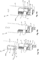
- a plurality of polyaxial bone anchoring devices 10 as described above are shown implanted in respective vertebrae 400.
- the rod 6 (not shown) may be inserted.
- Tube assemblies 20 are connected to polyaxial bone anchoring devices.
- Several steps of positioning and re-positioning of the receiving parts can be performed using one single actuator assembly 40 that is selectively connectable with the different tube assemblies 20.
- the actuator assembly 40 is easy to handle, the time for the adjustment steps when a plurality of bone anchoring devices have to be adjusted, may be shortened. The space needed with the instrument can be reduced.
- the arrangement, number, configuration and shape of the protrusions that form the driving and the driven portions may be different.
- the instrument is shown together with a polyaxial bone anchoring device of the bottom loading type with an outer locking ring, the instrument is not limited to be used only with such a device.
- the instrument can be used with any type of polyaxial bone anchoring device in which a clamping means is axially displaceable to clamp an inserted head.
Landscapes
- Health & Medical Sciences (AREA)
- Orthopedic Medicine & Surgery (AREA)
- Neurology (AREA)
- Life Sciences & Earth Sciences (AREA)
- Surgery (AREA)
- Heart & Thoracic Surgery (AREA)
- Engineering & Computer Science (AREA)
- Biomedical Technology (AREA)
- Nuclear Medicine, Radiotherapy & Molecular Imaging (AREA)
- Medical Informatics (AREA)
- Molecular Biology (AREA)
- Animal Behavior & Ethology (AREA)
- General Health & Medical Sciences (AREA)
- Public Health (AREA)
- Veterinary Medicine (AREA)
- Surgical Instruments (AREA)
Description
- The invention relates to an instrument for locking and unlocking a head of a bone anchor in a polyaxial bone anchoring device. The instrument comprises a tube assembly with an inner tube and an outer tube that are displaceable relative to each other for independently locking and unlocking the head and an actuator assembly for actuating the tube assembly. Such an instrument is particularly applicable to a polyaxial bone anchoring device that has a receiving part with a head receiving portion for receiving the head of the bone anchor and an outer locking ring for locking the head.
-
US 2013/0085536 A1 describes a polyaxial bone anchoring device including a receiving part with a rod receiving portion and head receiving portion for introducing and clamping of the head and a locking ring configured to be arranged around the head receiving portion. The locking ring includes an engagement structure for engagement with a tool to allow the locking ring to be moved out of the locking position, i.e. releasing the locking mechanism. The tool comprises a tubular member that is configured to engage the locking ring and a shaft acting on the receiving part. In one embodiment, unlocking of the head may be carried out while the rod is inserted. -
US 2013/0110179 A1 describes a set comprising a locking device and a separate unlocking device for locking and unlocking a multi-planar, taper lock screw. - In spinal surgery often multiple segments of the spinal column have to be corrected and/or stabilized using a spinal rod and polyaxial bone anchors. During such a procedure repeated adjustments of the bone anchoring element and the rod relative to the receiving part of a polyaxial bone anchoring device may become necessary.
-
US 2014/0236236 A1 discloses a helping means for a polyaxial pedicle screw which basically consists of a plunger, which can be brought into engagement with an inlay (power transfer member) inserted in a receiving sleeve of the pedicle screw, and a tension sleeve which can be brought into engagement with the receiving sleeve. A coupling or shaft nut may be screwed onto an external thread of the tension sleeve, such that when the shaft nut is rotated on the tension sleeve, radially projecting drive pins provided at the plunger are driven by the shaft and a relative movement is created between the plunger and the tension sleeve. -
US 2013/0085536 A1 discloses a tool cooperating with a bone anchoring device. The tool has includes a tubular member and shaft which has a rear end with a handle. The shaft has an outer thread portion at a distance from the handle that cooperates with an internal thread portion of the tubular member. A stop limits an insertion depth of the shaft in the tubular member. An insertion depth can be adjusted by the cooperation of the two threads. -
US 2005/0131408 A1 discloses a percutaneous access device arranged to engage a receiving member of a of a bone anchor assembly and which includes an inner tube and an outer tube disposed about at least a portion of the inner tube. An adjustment mechanism in the form of a hollow tubular cap allows an operator to adjust the relative longitudinal position of the inner and outer tubes. The cap has internal threads that engage external threads provided on a proximal end of the outer tube. The threads allow the cap to be longitudinally adjusted relative to the outer tube. The inner tube is connected to the cap and thus moves with the cap. - It is an object of the invention to provide an improved instrument for carrying out revisions or further positioning or repositioning of a polyaxial bone anchoring device with respect to a rod during surgery that is simple to handle for a user and that permits a greater variety of correction steps during surgery. It is a further object to provide a system of such an instrument and a polyaxial bone anchoring device adapted for use with the instrument.
- The object is solved by in instrument according to
claim 1 and by a system according to claim 14. Further developments are given in the dependent claims. - With the instrument the correction steps that are necessary for adjusting the bone anchoring elements and the rod and also the adjustment of the position of one or more vertebrae are simplified. In a first aspect, a temporary locking of the bone anchoring element in the receiving part can be effected using only the instrument with the rod already inserted into the receiving part but without the aid of a locking element such a set screw. As a result thereof, the polyaxial bone anchoring device allows to adjust or re-adjust an angular position of the receiving part relative to the bone anchoring device several times while the rod is already inserted. The temporary locking of the head using the instrument also permits to use the polyaxial bone anchoring device like a monoaxial bone anchoring device.
- The receiving part of the polyaxial bone anchoring device may comprise extended tabs that allow the rod during the adjustment step to be on a position higher above the head compared to a receiving part without extended tabs. Hence, with the instrument, it is also possible to correct a position of a vertebra in that the polyaxial bone anchoring device together with the associated vertebra is pulled against the rod.
- The instrument can be easily switched between an unlocking configuration in which the instrument allows pivoting of the head in the receiving part and a locking configuration in which the instruments effects a locking of the head in the receiving part and vice-versa. The switching can be effected by rotating the actuator assembly. An actuating mechanism of the actuator assembly of the instrument is designed such that the locking and unlocking of the head can be effected by the same grasping movement of a user. Hence, the operation of the instrument is easily to be learnt and memorized by a user and the risk of operating errors is reduced which results in an enhanced safety during surgery.
- In a further aspect, the actuator assembly may be removably connectable to the tube assembly, Thereby it is possible to adjust a plurality of polyaxial bone anchoring devices that each are connected to a tube assembly with one single actuator assembly one after the other. As the tube assemblies may be positioned close to each other, operating with one single actuator assembly is convenient in view of the reduced available space. The tube assemblies may be all the same or differ with respect to their length or other features such as the engagement features for engagement with the polyaxial bone anchoring device. Hence, the instrument may also provide a modular system that includes an actuator assembly and different tube assemblies that are adapted to be used with the actuator assembly.
- The instrument may additionally produce a tactile or audible sign when it enters one of the different configurations of locking, unlocking or removing. This further increases the safety and user-friendliness.
- Further features and advantages of the invention will become apparent from the description of embodiments by means of the accompanying drawings. In the drawings:
- Fig. 1
- shows a perspective view of the instrument according to an embodiment.
- Fig. 2
- shows an exploded perspective view of the instrument.
- Fig. 3
- shows an exploded perspective view of the tube assembly of the instrument of
Figs. 1 and 2 . - Fig. 4
- shows a perspective view of the tube assembly of
Fig. 3 in an assembled state. - Fig. 5
- shows an enlarged perspective view of a front portion of the tube assembly of
Fig. 4 in the assembled state. - Fig. 6a
- shows an enlarged cross-sectional view of a portion of the tube assembly of
Figs. 3 and 4 with details of a stopper member in a first configuration. - Fig. 6b
- shows an enlarged cross-sectional view of a portion of the tube assembly of
Figs. 3 and 4 with details of the stopper member in a second configuration. - Fig. 7a
- shows an enlarged perspective view of an upper portion of the tube assembly of
Fig. 4 in a first configuration. - Fig. 7b
- shows an enlarged perspective view of an upper portion of the tube assembly of
Fig. 4 in a second configuration. - Fig. 8
- shows an exploded perspective view of an actuator assembly of the instrument according to the embodiment.
- Fig. 9
- shows the actuator assembly of
Fig. 8 in an assembled state in an angled configuration of a lever assembly that is part of the actuator assembly. - Fig. 10
- shows a top view of the actuator assembly of
Figs. 8 and 9 . - Fig. 11a
- shows a cross-sectional view along line A-A in
Fig. 10 of the actuator assembly ofFigs. 8 to 10 in the configuration shown inFig. 9 . - Fig. 11b
- shows a cross-sectional view along line A-A in
Fig. 10 of the actuator assembly ofFigs. 8 to 10 in a straight configuration of the lever assembly. - Fig. 12
- shows an exploded perspective view of a polyaxial bone anchoring device according to an embodiment.
- Fig. 13
- shows a perspective view of the polyaxial bone anchoring device of
Fig. 12 in an assembled state. - Fig. 14
- shows an enlarged perspective view of a detail of
Fig. 13 . - Figs. 15a to 15c
- show perspective views of steps of connecting the instrument to the polyaxial bone anchoring device.
- Figs. 16a to 16c
- show cross-sectional views of steps of actuating a locking ring of the polyaxial bone anchoring device relative to the receiving part using the instrument, wherein the cross-section is taken in a plane extending through the central axis of the receiving part and including an angle of about 45° relative to an axis of an inserted rod.
- Figs. 17a to 17e
- show perspective views of steps of operating the instrument.
- Fig. 18
- shows a perspective view of a spinal column with a plurality of polyaxial bone anchoring devices and a plurality of tube assemblies connected to polyaxial bone anchoring devices and one single actuator assembly.
- Referring to
Figs. 1 to 3 , in one embodiment, the instrument comprises atube assembly 20 and anactuator assembly 40 that is removably connectable to thetube assembly 20. As shown inFig. 1 , thetube assembly 20 is connectable to a polyaxialbone anchoring device 10. - The
tube assembly 20 includes anouter tube 21 and aninner tube 31 and a longitudinal axis or tube axis L. Theouter tube 21 and theinner tube 31 are in the assembled state axially displaceable relative to each other along the longitudinal axis L to a certain extent that permits to move a portion of the polyaxial bone anchoring device from an unlocking position of a bone anchor to a locking position of a bone anchor and vice-versa. The displacement of theinner tube 31 and theouter tube 21 relative to each other is effected by theactuator assembly 40 as explained below. - As shown more in detail in
Figs. 2 to 5 , theouter tube 21 comprises afront end 21a and arear end 21b opposite to thefront end 21 a. A front portion of the instrument adjacent to thefront end 21a may taper in asection 22 towards thefront end 21a to reduce an overall space needed by the instrument when attached to the polyaxialbone anchoring device 10. - A
recess 24 is formed that extends from thefront end 21a of theouter tube 21 to a distance thereof. Therecess 24 has a width in the circumferential direction that is larger than an upper width of the polyaxialbone anchoring device 10 and a height that permits arod 6 as shown inFig. 1 to extend therethrough and to be movable in an axial direction within the recess 24 (Fig. 1 ). At a distance from thefront end 21a of theouter tube 21 anengagement portion 25 that is adapted to engage a corresponding engagement portion of the polyaxialbone anchoring device 10 is provided. Theengagement portion 25 may be in the form of a circumferentially extending rib that cooperates with a corresponding groove at the polyaxialbone anchoring device 10. At a distance towards therear end 21b of the outer tube, a stepped portion or circumferentially extendingshoulder 26 is provided that forms an abutment for theinner tube 31. - As best seen in
Figs. 3, 4 and7a, 7b , adjacent to therear end 21b of theouter tube 21 a cut-out orrecess 27 is formed on each side of the longitudinal axis L wherein therecess 27 extends to a distance from therear end 21b. Eachrecess 27 has in a perspective view, seen inFigs. 7a and 7b , a substantially step-like shape forming afirst recess area 27a that is open to therear end 21b and adjacent thereto in a circumferential direction asecond recess area 27b that has a smaller width and extends from a distance from therear end 21b farther down, i.e. towards thefront end 21a compared to thefirst recess area 27a. Therecess 27 has the function to accommodate driving portions of the actuator assembly and driven portions from theinner tube 31 therein. The orientation of therecess 27 is such that therecess 27 is substantially aligned with theengagement portion 25 at thefront end 21a. - At a distance from the
rear end 21b anelongate hole 28 is provided in theouter tube 21 wherein the longer axis of theelongate hole 28 is coaxial to the longitudinal axis L. Theelongate hole 28 is located at a circumferential position slightly offset from the middle of therecess 24 at thefront end 21a. Through the elongate hole 28 a pin connected to a stopper member may pass to enable a limited motion of the stopper member. - In addition, longitudinally extending substantially
parallel grooves outer tube 21. Thegrooves middle groove 29a may extend up to therear end 21b. Moreover, coaxially extendingposition markings outer tube 21. Theposition markings outer tube 21 and serve for indicating in cooperation with a marking on theactuator assembly 40 to indicate an actuating position of locking or unlocking (markings actuator assembly 40. The middle marking 200a indicating the removing position may be longer than the other markings. - Turning now again to
Fig. 3 , theinner tube 31 comprises afront end 31a and arear end 31b. An inner diameter of theinner tube 31 is such that a fixation element such as a set screw or a further instrument can pass through. In a front portion adjacent to thefront end 31a arecess 34 is formed that substantially corresponds to therecess 24 of theouter tube 21, such that when theinner tube 31 is in theouter tube 21 therecesses front end 31a anengagement structure 35 is provided that is configured to cooperate with a corresponding engagement structure at the polyaxial bone anchoring device. Theengagement structure 35 in the embodiment shown is a circumferentially extending groove that may cooperate with a circumferentially extending rib at the polyaxial bone anchoring device. At an end of therecess 34 opposite to thefront portion 31a and located in a circumferential direction only at one side of the recess 34 a further recess or cut-out 36 extends deeper into theinner tube 31 in an axial direction. The cut-out 36 serves for accommodating an end portion of astopper member 300 explained below. From the end of the recess 36 a recessedsurface portion 37 is provided in the outer surface of theinner tube 31. The recessedsurface portion 37 is elongated in an axial direction and formed and sized so as to receive and guide thestopper member 300 therein. The recessedsurface portion 37 may also have a widenedend portion 37a in a direction towards therear end 31b. At around or slightly above thewidened end portion 37a a circumferentially extending outer narrow shoulder 37b is provided that forms an abutment for thestopper member 300. Spaced apart from the shoulder 37b is anannular protrusion 38 that serves for axially supporting aspring element 30, for example a coil spring, that acts onto thestopper member 300. - In the upper region of the
inner tube 31first protrusions actuator assembly 40 to displace theinner tube 31 relative to theouter tube 21. Two sets offirst protrusions Figs. 3, 4 and7a, 7b , oneprotrusion 39a is located at a first distance from therear end 31b and theother protrusion 39b is provided at a second distance greater than the first distance from therear end 31b and is circumferentially offset from theprotrusion 39a. Theprotrusions outer tube 21 when theinner tube 31 and theouter tube 21 are assembled. As depicted more in detail inFigs. 7a and 7b , in the assembled state, theprotrusion 39a that is closer to therear end 31a of theinner tube 31 is located in thefirst recess area 27a of therecess 27 of the outer tube and thesecond protrusion 39b is located in the lowermost portion of therecess area 27b of therecess 27 of theouter tube 21. The distance of theprotrusions first protrusion 39a and an opposing sidewall of therecess 27 that serves for entering driving portions of the actuator assembly into therecess 27. Theinner tube 31 may be assembled with theouter tube 21 by first introducing thelower protrusion 39b into therecess 27, rotating theinner tube 31 relative to theouter tube 21 and then entering thefirst protrusion 39a into therecess 27. - Referring more in detail to
Figs. 3, 4 and6a, 6b thestopper member 300 may be provided to inhibit rotation of thetube assembly 20 relative to the polyaxialbone anchoring device 10 into a position where it can be disengaged from the polyaxialbone anchoring device 10. - The
stopper member 300 includes ashaft portion 301 and abase portion 302 that encompasses theinner tube 31 approximately in a mid-portion thereof. Theshaft portion 301 is received and guided in the recessedsurface portion 37 of theinner tube 31. A freefront end 300a of theshaft portion 301 is thickened, so that it can protrude into a channel for the rod of the polyaxialbone anchoring device 10 and block a rotational motion of thetube assembly 20 relative to the polyaxialbone anchoring device 10. In particular, the thickenedportion 300a can extend into the cut-out 36 of theinner tube 31. Thebase portion 302 has the shape of a segment of a tube and is configured to encompass theinner tube 31 over a circumferential area. Anupper edge 300b opposite to thefront end 300a of theshaft portion 301 faces in the direction of therear end 31b of theinner tube 31. In addition, apin 303 is fixed to thebase portion 302. Thepin 303 has at its free end a knob-like shape that can be actuated by a user. In an assembled state of theinner tube 31 and theouter tube 21 thepin 303 protrudes out of theelongate opening 28 of theouter tube 21 as shown inFig. 4 . - Referring now to
Figs. 7a and 7b , thetube assembly 20 engages an upper portion of a receivingpart 5 of the polyaxialbone anchoring device 10 that comprises a recess orchannel 92 for the rod. In the assembled state of theinner tube 31 and theouter tube 21, thespring member 30 is placed around theinner tube 31 between theannular protrusion 38 and the shoulder 37b. When thestopper member 300 is mounted, a lower end of thespring member 30 abuts against theupper edge 300b of thestopper member 300 and biases thestopper member 300 into its lowermost position, in which thepin 303 is close to the bottom end of the elongate opening 28 (Fig. 4 andFig. 6b ). Hence, in the lowermost position, thestopper member 300 protrudes with its thickenedfront end 300a into therecess 92 of the receivingpart 5 and blocks rotation of thetube assembly 20 back from an engaged position to a position where thetube assembly 20 can be removed. When a user pulls thepin 303 upward, i.e. in the direction towards therear end 31b of theinner tube 31 against the spring force of thespring member 30, thethickened end portion 300a of the stopper member does no longer protrude into therecess 92 of the receivingpart 5 and the tube assembly can be rotation back to be disengaged from the polyaxialbone anchoring device 10. Thus, thestopper member 300 is arranged and biased in such a manner that it has to be actively pulled upward if thetube assembly 20 shall be removed from a polyaxialbone anchoring device 10 to which it is engaged. This enhances the safety of handling during surgery. - Next, the actuator assembly will be described referring more in detail to
Figs. 8 to 10 and11a, 11b . Theactuator assembly 40 comprises aninner sleeve 41, anouter sleeve 51 and alever assembly 61 in the form of a toggle lever and also ahandle portion 70. Referring more in detail toFigs. 11a and 11b , theouter sleeve 51 has afront end 51a and arear end 51b. Aninternal thread 52 is provided at or near therear end 51b that allows to connect thehandle portion 70 to theouter sleeve 51. An inner diameter of theouter sleeve 52 is smaller in an upper region adjacent theinternal thread 52 than in a lower region adjacent to thefront end 51a such that at a distance from therear end 51b aninner shoulder 53 is formed that serves as an abutment for theinner sleeve 51. Above theinner shoulder 53, aninner protrusion 54 is formed, on each side of the longitudinal axis, i.e. there are twoinner protrusions 54 offset by 180°. Theprotrusions 54 form second protrusions compared to the first protrusions of thetube assembly 20. They may have a substantially square-shaped contour and serve as driving portions for transferring the actuating movement of thelever assembly 61 to thetube assembly 20 as explained in detail below. Theinner protrusions 54 are arranged in a circumferential direction substantially at 90° with respect to the arrangement of thelever assembly 61. - Adjacent to the
rear end 51b ahinge 55 is provided that serves for attachment of one of the lever arms of thelever assembly 61, more specifically that provides one rotation point of the toggle lever. A plurality ofelongate openings 57 are provided circumferentially that facilitate cleaning. In addition, anelongate slot 58 extends from thefront end 51a to a distance from the front end in a coaxial direction at the same circumferential position as thehinge 55. Theslot 58 permits a hinge provided at theinner sleeve 41 to protrude therethrough. - At around 90° in a circumferential direction markings are provided that indicate a position and/or a function of the actuator assembly. For example, adjacent to the
front end 51a at around 90° offset from the position of thehinge 55 in a circumferential direction a position marking 56 that may be a coaxial line, is provided that is configured to be aligned with the middle marking 200a of the position markings of theouter tube 21 of thetube assembly 20 when theactuator assembly 40 is connected to or removed from thetube assembly 20. Moreover, adjacent to therear end 51b, function indications "LOCK", "REMOVE", "UNLOCK" may be provided, for example with additional arrows that indicate the direction of rotation to achieve a locking position, an unlocking position and a remove position of theactuator assembly 40. - The
inner sleeve 41 comprises afront end 41a and a rear end 41b and has an axial length that is shorter than the axial length of theouter sleeve 51 so that the inner sleeve can be fully accommodated in theouter sleeve 51 and can abut with its rear end 41b against theinner shoulder 53 of theouter sleeve 51. Theinner sleeve 41 comprises twoinner protrusions 42 adjacent to its rear end 41b and offset from each other by 180°. Theinner protrusions 42 are similar to theinner protrusions 54 of theouter sleeve 51, i.e. have a substantially square-shaped contour. In the assembled state theinner protrusions 42 of theinner sleeve 41 are aligned with theinner protrusions 54 of theouter sleeve 51 in the axial direction. Like theinner protrusions 54, theinner protrusions 42 are second protrusions when compared to thefirst protrusions tube assembly 20 and also serve as a driving portions that are configured to transfer the actuating movement of theactuator assembly 40 to thetube assembly 20. - Adjacent to the
front end 41a, at the same circumferential position as thefirst hinge 55 of theouter sleeve 51 asecond hinge 43 is provided that protrudes outward from the inner sleeve through theslot 58 in the assembled state. Thesecond hinge 43 serves as the second rotation point of the toggle lever. At an opposite side in an axial direction, i.e. around 90° offset from thehinge 43, aspring portion 44 may be formed for example by a cut-out in the wall surface of theinner sleeve 41. At a resilient free end of the spring portion 44 atiny pin 45 is fixed that slightly protrudes to the inside of theinner sleeve 41. Thepin 45 serves for being caught in thegrooves outer tube 21 of thetube assembly 20 to provide a tactile and/or audible sign to a user when a respective position of theactuator assembly 40 is attained. - The
lever assembly 61 comprises afirst lever arm 62 that is hingedly connected at one end via apin 63 to thesecond hinge 43 provided at theinner sleeve 41. A longer end portion orgrip portion 62a of thefirst lever arm 62 has a gripping structure at its side facing away from thesleeves second lever arm 64 of thelever assembly 61 is on one side hingedly connected via apin 64 to thefirst hinge 55 and at its second end via apin 65 hingedly connected to thefirst lever arm 62. The latter connection provides the third rotation point of the toggle lever. In the embodiment, thesecond lever arm 64 is shorter than thefirst lever arm 62. Thefirst lever arm 62 has a slightly angled shape. More specifically, as depicted inFigs. 11a and 11b , a length of thegrip portion 62a of thefirst lever arm 62 is such that the height position of the first lever arm substantially corresponds to the height position of thehandle portion 70. Moreover, thefirst lever arm 62 comprises a transversely extendingpin 67 that is in a direction to thegrip portion 62a located above the third rotation point defined by thepin 66. The transversely extendingpin 67 protrudes inward, i.e. towards thesecond lever arm 64, and may assist to push thesecond lever arm 64 into the straight position as seen inFig. 11b . - The
handle portion 70 has a threadedprojection 72 that allows it to be screwed into thefirst sleeve 51. Thehandle portion 70 may further comprise a grippingstructure 73 such as circumferential lobes or crests that facilitates gripping. A plurality of through-holes 74 may also be provided to facilitate cleaning. - Referring again to
Figs. 11a and 11b , in the assembled state of theinner sleeve 41 and theouter sleeve 51, asecond spring member 50, for example a coil spring is inserted into theouter sleeve 51 and is supported on one side by anannular ring 59, for example a split ring, that may be held in an annular groove near thefront end 51a of theouter sleeve 51. On the other side, thespring member 50 abuts against thefront end 41a of theinner sleeve 41. Thespring member 50 is configured to bias theinner sleeve 41 against theinner shoulder 53 of theouter sleeve 51 as depicted inFig. 11a . In this configuration, thelever assembly 61 is in the angled configuration where thefirst lever arm 62 and thesecond lever arm 64 are angled with respect to each other and thegrip portion 62a extends in an angled manner away from thehandle portion 70. This configuration is a default configuration due to the biasing of thesecond spring member 50. Theinner protrusions - When the
first lever arm 62 is pushed towards thehandle portion 70, the lever assembly assumes the straight configuration, where thefirst lever arm 62a and thesecond lever arm 64 are more parallel or less angled as shown inFig. 11b . Theinner sleeve 41 is pushed downward towards thefront end 51 a of theouter sleeve 51 whereby theinner protrusions - The instrument is made of a body-compatible material. In particular, titanium or stainless steel may be such a suitable material, but other materials could also be used as long as they are body-compatible.
- Referring now again to
Figs. 1, 2 and7a, 7b , the mounting of thetube assembly 20 and theactuator assembly 40 and the actuation of thetube assembly 20 by theactuator assembly 40 will be explained. Mounting of the actuator assembly is effected as follows. Theinner tube 31 is within theouter tube 21 and thesecond protrusions respective recess areas recess 27 of the outer tube. The position marking 200a that indicates the REMOVE position, is at a circumferential position that corresponds to the gap G between the wall of therecess 27 and thefirst protrusion 39a. Theactuator assembly 40 which is in the default configuration ofFig. 11a is mounted onto thetube assembly 20 in such an orientation that the position marking 56 is in line with the position marking 200a. This permits thesecond protrusions first protrusion 39a and the sidewall of therecess 27 at thetube assembly 20 when theactuator assembly 40 is moved onto thetube assembly 20. Removing is effected in the same position. Thesecond protrusions - The locking configuration of the instrument is attained as follows. When the
actuator assembly 40 is rotated in the clockwise direction, such that the position marking 56 is aligned with the position marking 200c indicated with "LOCK" thesecond protrusions actuator assembly 40 move into therecess area 27a. When the lever is actuated by pressing thefirst lever arm 62 in the direction of thehandle portion 70 so that the straight configuration (Fig. 11b ) is attained, thesecond protrusions Fig. 11b , thereby leaving a gap d between them in axial direction. As the wall of therecess 27 provides an abutment for thesecond protrusion 42 of theinner sleeve 41, thesecond protrusion 54 of theouter sleeve 51 presses thefirst protrusion 39a of theinner tube 31 upward towards therear end 21b of theouter tube 21 and thefirst protrusion 39b also moves upward with respect to the outer tube (Fig. 7b ). As a consequence, thefront ends - The unlocking configuration is attained by rotating the
actuator assembly 40 in the default configuration in a counter-clockwise direction such that the position marking 56 is aligned with the position marking 200b indicated with "UNLOCK". Thesecond protrusions second recess area 27b. Pushing thelever arm 62 spreads thesecond protrusions second protrusion 42 of theinner sleeve 41 pushes down thefirst protrusion 39b of theinner tube 31. The opposite border of therecess 27 serves as an abutment for thesecond protrusion 52 of the outer sleeve 51 (Fig. 7a ). As a consequence, thefront ends - Next, with reference to
Figs. 12 to 14 , a polyaxial bone anchoring device that is suitable for use with the instrument, will be explained. The polyaxialbone anchoring device 10 according to an embodiment comprises abone anchoring element 1 with ashank 2 and ahead 3 with a spherically-shaped outer surface portion. Thebone anchoring element 1 may be a bone screw with a threaded shank. Thehead 3 may have arecess 4 is provided for engagement with a tool, such as a driver. A receivingpart 5 is provided for receiving thehead 3 and connecting the bone anchoring element via thehead 3 to arod 6. In addition, afixation element 7 in the form of an inner screw or a set screw may be provided for fixing therod 6 in a receivingpart 5. Also, thebone anchoring device 10 includes alocking ring 8 for the locking thehead 3 in a receivingpart 5. - The receiving
part 5 has a first orupper end 5a and a second orlower end 5b. Adjacent to theupper end 5a, arod receiving portion 90 is provided and adjacent to thelower end 5b ahead receiving portion 100 is provided. Therod receiving portion 90 is substantially cylindrical and comprises acoaxial bore 91 that extends from theupper end 5a into thehead receiving portion 100. Thebore 91 comprises an internal thread in at least a region thereof for receiving thefixation element 7. A substantiallyU-shaped recess 92 that forms a channel for receiving therod 6 extends from theupper end 5a to almost the beginning of thehead receiving portion 100. At a distance from theupper end 5a a groove or otherwise weakenedsection 93 is provided that allows to break-off the upper portions of the receiving part formed by the U-shaped recess that serve as extended tabs. By means of the long extended tabs it is possible to manipulate the polyaxial bone anchoring device with an insertedrod 6 that is at a higher position compared to the final position so that, for example, a vertebra can be pulled against the rod. - At an outer surface of the
rod receiving portion 90 an engagement structure for engagement with the tube assembly is provided. The engagement structure may comprise circumferentially extendingribs 94. Theribs 94 are arranged asymmetrical with respect to a plane including a central axis C of the receiving part and a channel axis of the substantiallyU-shaped recess 92. That means, afirst rib 94 starts at theU-shaped recess 92 on one side and extends to a distance around the receiving part and thesecond rib 94 starts at the opposite side of the U-shaped recess relative to the central axis C and extends from there to a distance around the receivingpart 5. Thereby, a rib-free surface 95 is formed on each side from the U-shaped recess. - The
head receiving portion 100 has a substantially cap-like shape with a hollow substantially spherical interior portion 101 (seeFigs. 16a to 16c ) for receiving thehead 3 pivotably therein. A plurality ofslits 102 render the head receiving portion flexible so that when pressure is exerted onto the head receiving portion by the lockingring 8, thehead 3 can be clamped and finally locked. - The
locking ring 8 is designed to encompass the head receiving portion and has an internal surface structure that allows to achieve in corporation with the head receiving portion a full locking of thehead 3 in thehead receiving portion 100 when the locking ring in its lowermost position and a pre-locking when the locking ring is in a position slightly above the lowermost position which allows still pivoting of thehead 3 in the head receiving portion but prevents removal of thehead 3 from thehead receiving portion 100. Thelocking ring 8 further has plurality of upstandingflexible sections 81 that may serve for engagement with a receiving part to preliminarily hold the locking ring in a pre-locking position. Also, twoopposite projections 82 are provided at an upper side of the locking ring that serve for supporting therod 6. In the embodiment shown, thelocking ring 8 also comprises twoupstanding arms 83 that are asymmetrically with respect to a plane that extends through the central axis C and through the mid of therod support projections 82 in the same manner as theribs 94 ofrod receiving portion 90 are arranged. At an upper end of thearms 83 an engagement structure in the form ofgrooves 84 is provided that is configured to be engaged by thetube assembly 20 of the instrument. As depicted inFigs. 13 and 14 , in the assembled state, the engagement structure in the form of theribs 94 on the receiving part and the engagement structure in the form of thegrooves 83 is aligned, leaving the rib-free surface 95 of thehead receiving portion 90 exposed. Theupstanding arms 83 of the locking ring with theengagement structure 84 at or near their upper end facilitate finding of the engagement structure with the instrument. - In the following, use of the instrument will be explained. Referring first to
Figs. 15a to 15c , the steps of attaching the instrument to the polyaxial bone anchoring device are illustrated. The bone anchoring element may be implanted in a vertebra or other bone. Thelocking ring 8 is in an axial position in which it does not fully lock the head but thehead 3 is prevented from removal from thehead receiving portion 100. Therod 6 is inserted into the substantiallyU-shaped recess 92. Also, thefixation element 7 may be already screwed into thebore 91 of the receivingpart 5. - Due to the extended tabs, the rod is still movable not only along the rod axis but also in an axial direction. The
engagement portions 25 of theouter tube inner tube 31 have their closest distance from each other which is defined by an abutment of thefront portion 31a of theinner tube 31 against theinner shoulder 26 of the outer tube. Thestopper member 300 is in the default position that means it is protruding downward in the cutout 36 (seeFig. 3 ). In this configuration, the instrument is moved downward so that thefront portions 31a of theinner tube outer surface portion 95 of the receivingpart 5. - Next, as shown in
Fig. 15b , the front portions of thetube assembly 20 of the instrument move along the rib-free surface portions 95 of the receivingpart 5 to a position, where the engagement portions in form of theribs 25 of the outer tube and thegrooves 35 of theinner tube 31 are on the same axial position as the corresponding engagement portions in the form of thegrooves 84 of the locking ring and theribs 94 of the receivingpart 5. At the same time, thestopper member 300 is retracted by pulling upwards of the pin 303 (not shown). - As depicted in
Fig. 15c , the instrument is then rotated so that the engagement portions at the instrument and the engagement portions at the locking ring and the receiving part engage. More in detail, therib 25 at the outer tube engages thegroove 84 at the locking ring and therib 94 at the receivingpart 5 engages thegrooves 35 at theinner tube 31. After engagement, thestopper member 300 can be released so that it is biased downward and thethickened end portion 300a protrudes into theU-shaped recess 92 of the receivingpart 5. There, thethickened end portion 300a of thestopper member 300 abuts against the sides of theU-shaped recess 92. If for some reason a user tries to rotate back the instrument out of the engagement with the receiving part and the locking ring. Hence, such back-rotation is prevented by thestopper member 300. This enhances the safety of the device during surgery. For disengagement of thetube assembly 20, thestopper member 300 may be retracted so that the instrument can be rotated back out of engagement and removed along the rib-free portions 95 of the receivingpart 5. - Referring now to
Figs. 16a to 16c , the function of locking and unlocking of thehead 3 in thehead receiving portion 100 of the receiving part with the instrument will be explained. InFig. 16a , the instrument is in the engaged configuration ofFig. 15c where the engagement portions of the outer tube engage the engagement portions of the locking ring and the engagement portions of the inner tube engage the engagement portions of the receiving part. Thelocking ring 8 is in an upper position in an axial direction where thehead 3 is still pivotable in the head receiving portion but is prevented from removal from thehead receiving portion 100. Theline 500 indicates a bone surface. The front portions of theinner tube 31 and theouter tube 21 of the tube assembly have their smallest distance from each other. The actuator assembly is in the configuration "UNLOCKED". In this configuration, adjustments of the angle of the receiving part and the locking ring relative to thebone anchoring element 1 can be performed with the instrument. -
Fig. 16b depicts a locking position of thelocking ring 8. In the locking position, thelocking ring 8 is moved downward so that it fully clamps and locks thehead 3 in thehead receiving portion 100. This is achieved by moving downward thelocking ring 8 with theouter tube 21 that is driven downward by theactuator assembly 40 when theactuator assembly 40 is in the configuration "LOCKED". As can be seen, the distance between the engagement portions of the receivingpart 5 and thelocking ring 8 has been increased. Thefront portion 31a of theinner tube 31 does no longer abut against theinner shoulder 26 of theouter tube 21. In the locked configuration, it is possible to pull the associated vertebra for abone 500 upward with the instrument towards the insertedrod 6. - Finally, as shown in
Fig. 16c , thefixation element 7 can be tightened to fix the locked configuration. - Referring now to
Figs. 17a to 17e , the handling of the actuator assembly corresponding to locking and unlocking of thehead 3 in thehead receiving portion 100 will be explained. As depicted inFig. 17a , to obtain the locked configuration, theactuator assembly 40 is rotated in a clockwise direction in its default configuration, where thelever system 61 is in the angled configuration. When the position marking 56 is aligned with the position marking 200c for the locked configuration, the lever arm is pushed with the hand against thegrip portion 70 as shown inFig. 17b to achieve locking of thehead 3, as shown inFig. 16b . - To release the locked configuration, the
lever arm 61 of theactuator assembly 40 is no longer pushed against the grip portion so that it returns to the default configuration as shown inFig. 17c . Then, theactuator assembly 40 can be rotated in the counter-clockwise direction as shown inFig. 17d until the position marking 56 of theactuator assembly 40 is aligned with the position marking 200b on the outer tube as depicted inFig. 17d . Next, as shown inFig. 17e , thelever arm 61 is pushed against thegrip portion 70 so that the toggle lever attains the straight configuration to achieve unlocking of thehead 3 as shown inFig. 16a . - Each time when the
actuator assembly 40 is rotated into one of the positions "LOCK", "UNLOCK" or "REMOVE", thetiny pin 45 of thespring 44 of theinner tube 41 comes to rest in acorresponding groove Fig. 3 ) and produces a tactile or audible sign that indicates the user that the respective position is reached. - Turning now to
Fig. 18 , a plurality of polyaxialbone anchoring devices 10 as described above are shown implanted inrespective vertebrae 400. The rod 6 (not shown) may be inserted.Tube assemblies 20 are connected to polyaxial bone anchoring devices. Several steps of positioning and re-positioning of the receiving parts can be performed using onesingle actuator assembly 40 that is selectively connectable with thedifferent tube assemblies 20. As theactuator assembly 40 is easy to handle, the time for the adjustment steps when a plurality of bone anchoring devices have to be adjusted, may be shortened. The space needed with the instrument can be reduced. - Various modifications can be contemplated. For example, the arrangement, number, configuration and shape of the protrusions that form the driving and the driven portions may be different. Although the instrument is shown together with a polyaxial bone anchoring device of the bottom loading type with an outer locking ring, the instrument is not limited to be used only with such a device. For example, the instrument can be used with any type of polyaxial bone anchoring device in which a clamping means is axially displaceable to clamp an inserted head.
Claims (15)
- An instrument for locking and unlocking a head of a bone anchor in a receiving part of a polyaxial bone anchoring device, the instrument comprising
a tube assembly (20) comprising
an inner tube (31) adapted to engage a first portion of a polyaxial bone anchoring device (10),
an outer tube (21) adapted to engage a second portion of a polyaxial bone anchoring device (10), the tube assembly having a longitudinal axis (L),
wherein the outer tube (21) is displaceable relative to the inner tube (31) from a first axial position to a second axial position and vice versa,
wherein the first axial position is associated with an unlocking configuration of the polyaxial bone anchoring device in which the head (3) is pivotable, and the second axial position is associated with a locking configuration of the polyaxial bone anchoring device in which the head (3) is locked;
an actuator assembly (40) comprising an actuating mechanism (61) for displacing the inner tube (31), relative to the outer tube (21), ,
wherein the actuator assembly (40) comprises at least two driving portions (54, 42) that are configured to be displaceable parallel to the longitudinal axis in response to an operation of the actuating mechanism (61) and
wherein the tube assembly (20) comprises at least two driven portions (39a, 39b) that are configured to be driven by the driving portions (54, 42);
and wherein the at least two driven portions (39a, 39b) are circumferentially spaced apart from each other. - The instrument of claim 1, wherein the actuator assembly (40) is rotatable around the longitudinal axis (L) to a first rotational position wherein the actuator assembly (40) is configured to actuate the tube assembly (20) to assume the first axial position and to a second rotational position wherein the actuator assembly (40) is configured to actuate the tube assembly (20) to assume the second axial position and wherein the at least two driven portions (39a, 39b) that are circumferentially spaced apart from each other are corresponding to the first and second rotational positions of the actuator assembly (40).
- The instrument of claim 1 or 2, wherein the actuator assembly (40) is removably connectable to the tube assembly (20).
- The instrument of claim 3, wherein the actuator assembly (40) is rotatable around the longitudinal axis (L) to a third rotational position wherein the actuator assembly (40) is connectable to and/or removable from the tube assembly (20).
- The instrument of one of claims 1 to 4, wherein the actuating mechanism (61) has a first configuration that is associated with each of the first rotational position of the actuator assembly (40) and the second rotational position of the actuator assembly (40).
- The instrument of claim 4 or 5, wherein the actuating mechanism (61) has a second configuration that is associated with the third rotational position of the actuator assembly (40).
- The instrument of claim 6, wherein the actuating mechanism (61) comprises a lever (62, 64) and wherein the first configuration corresponds to a first lever position and the second configuration corresponds to a second lever position.
- The instrument of one of claims 1 to 7, wherein by the circumferentially spaced apart driven portions (39a, 39b) a gap (G) is provided that permits the driving portions (54, 42) to enter.
- The instrument of one of claims 1 to 8, wherein the actuator assembly (40) comprises an outer sleeve (51) and an inner sleeve (41) axially displaceable with respect to each other upon operation of the actuating mechanism (61) and wherein the actuating mechanism (61) is preferably a toggle lever with a first lever arm (64) hingedly connected to the outer sleeve and a second lever arm (62) hingedly connected to the inner sleeve (41).
- The instrument of claim 9, wherein the outer sleeve (51) comprises a first driving portion (54) and the inner sleeve (61) comprises a second driving portion (42) and wherein the first and the second driving portions are axially aligned.
- The instrument of one of claims 5 to 10, wherein the actuator assembly (40) comprises a spring member (50) that biases the actuating mechanism (61) into the second configuration.
- The instrument of one of claims 1 to 11, wherein the actuator assembly (40) comprises a grip portion (70) that allows an operator to exert a counter force when actuating the actuating mechanism (61).
- The instrument of one of claims 1 to 12, further comprising a stopper member (300) which is arranged to be movable along the longitudinal axis of the tube assembly (20) in order to attain a first position in which it impedes a rotational movement of the tube assembly (20) with respect to the polyaxial bone anchoring device (10), and preferably to attain a second position, in which it does not impede a rotational movement of the tube assembly (20).
- A system of an instrument according to one of claims 1 to 13 and a polyaxial bone anchoring device, wherein the polyaxial bone anchoring device (10) comprises a bone anchoring element (1) for anchoring in a bone and a receiving part (5) for receiving a head (3) of the bone anchoring element and wherein a clamping device (8) is provided that acts upon the head (3) in the receiving part to lock the head (3) in the receiving part, and wherein the receiving part (5) and the clamping device (8) each comprise an engagement structure (84, 94) configured to be engaged by an engagement structure (25, 35) at the outer tube (21) and the inner tube (31) respectively.
- The system of claim 14, wherein the polyaxial bone anchoring device further comprises a rod receiving portion (90) and a recess (92) for receiving a rod (6), the rod receiving portion (90) further comprising a first engagement structure (94) for engagement with the instrument; anda head receiving portion (100) for accommodating the head (3) of a bone anchoring element, the head receiving portion (100) being flexible for inserting and clamping the head; anda locking ring (8) configured to be arranged around the head receiving portion (100), the locking ring comprising a second engagement structure (84) for engagement with the instrument.
Priority Applications (6)
| Application Number | Priority Date | Filing Date | Title |
|---|---|---|---|
| EP16185546.5A EP3287088B1 (en) | 2016-08-24 | 2016-08-24 | Instrument for locking and unlocking a head of a bone anchor in a polyaxial bone anchoring device |
| US15/669,604 US10470805B2 (en) | 2016-08-24 | 2017-08-04 | Instrument for locking and unlocking a head of a bone anchor in a polyaxial bone anchoring device |
| CN201710722369.7A CN107773298B (en) | 2016-08-24 | 2017-08-22 | Instrument for locking and unlocking the head of a bone anchor in a polyaxial bone anchoring device |
| JP2017160565A JP7029905B2 (en) | 2016-08-24 | 2017-08-23 | A device for locking and unlocking the head of a bone anchor in a multi-axis bone anchor device |
| US16/571,858 US11076895B2 (en) | 2016-08-24 | 2019-09-16 | Instrument for locking and unlocking a head of a bone anchor in a polyaxial bone anchoring device |
| US17/359,045 US11771478B2 (en) | 2016-08-24 | 2021-06-25 | Instrument for locking and unlocking a head of a bone anchor in a polyaxial bone anchoring device |
Applications Claiming Priority (1)
| Application Number | Priority Date | Filing Date | Title |
|---|---|---|---|
| EP16185546.5A EP3287088B1 (en) | 2016-08-24 | 2016-08-24 | Instrument for locking and unlocking a head of a bone anchor in a polyaxial bone anchoring device |
Publications (2)
| Publication Number | Publication Date |
|---|---|
| EP3287088A1 EP3287088A1 (en) | 2018-02-28 |
| EP3287088B1 true EP3287088B1 (en) | 2019-01-09 |
Family
ID=56799362
Family Applications (1)
| Application Number | Title | Priority Date | Filing Date |
|---|---|---|---|
| EP16185546.5A Active EP3287088B1 (en) | 2016-08-24 | 2016-08-24 | Instrument for locking and unlocking a head of a bone anchor in a polyaxial bone anchoring device |
Country Status (4)
| Country | Link |
|---|---|
| US (3) | US10470805B2 (en) |
| EP (1) | EP3287088B1 (en) |
| JP (1) | JP7029905B2 (en) |
| CN (1) | CN107773298B (en) |
Cited By (2)
| Publication number | Priority date | Publication date | Assignee | Title |
|---|---|---|---|---|
| DE102021134253B3 (en) | 2021-12-03 | 2022-12-29 | Medizintechnik Sattler Gmbh | quick release clamp |
| EP4190273A1 (en) | 2021-12-03 | 2023-06-07 | Medizintechnik Sattler GmbH | Quick-action clamping clamp |
Families Citing this family (17)
| Publication number | Priority date | Publication date | Assignee | Title |
|---|---|---|---|---|
| FR3035318B1 (en) * | 2015-04-24 | 2017-05-19 | Medicrea Int | MATERIAL OF VERTEBRAL OSTEOSYNTHESIS |
| WO2018183314A1 (en) | 2017-03-30 | 2018-10-04 | K2M, Inc. | Bone anchor apparatus and method of use thereof |
| US11419639B2 (en) | 2017-03-30 | 2022-08-23 | K2M, Inc. | Modular offset screw |
| WO2018183489A1 (en) | 2017-03-30 | 2018-10-04 | K2M, Inc. | Modular screw |
| EP3636185B1 (en) | 2018-10-09 | 2023-12-06 | Biedermann Technologies GmbH & Co. KG | System for correcting the position of bones, bone parts or vertebrae |
| US10779893B2 (en) * | 2018-10-18 | 2020-09-22 | Warsaw Orthopedic, Inc. | Spinal implant system and method |
| US10799300B2 (en) * | 2018-10-18 | 2020-10-13 | Warsaw Orthopedic, Inc. | Spinal implant system and method |
| US11553947B2 (en) * | 2019-07-16 | 2023-01-17 | Aesculap Implant Systems, Llc | Spinal deformity sequential persuader |
| EP3838196B1 (en) | 2019-12-18 | 2024-01-31 | Biedermann Technologies GmbH & Co. KG | Coupling device and instrument for placing a coupling device to a head of a bone anchor |
| DE102020005928A1 (en) * | 2020-09-28 | 2022-03-31 | Mimeo Medical Gmbh | Modular and temporarily fixable vertebral osteosynthesis device |
| US11627998B2 (en) | 2020-12-11 | 2023-04-18 | Warsaw Orthopedic, Inc. | Head position and driver combination instrument |
| US20220280207A1 (en) * | 2021-03-05 | 2022-09-08 | Medos International Sarl | Sequential reducer |
| US11291477B1 (en) | 2021-05-04 | 2022-04-05 | Warsaw Orthopedic, Inc. | Dorsal adjusting implant and methods of use |
| US11432848B1 (en) | 2021-05-12 | 2022-09-06 | Warsaw Orthopedic, Inc. | Top loading quick lock construct |
| US11712270B2 (en) | 2021-05-17 | 2023-08-01 | Warsaw Orthopedic, Inc. | Quick lock clamp constructs and associated methods |
| EP4129220A1 (en) * | 2021-08-04 | 2023-02-08 | Biedermann Technologies GmbH & Co. KG | Coupling device for coupling a rod to a bone anchoring element and method of manufacturing the same |
| US11957391B2 (en) | 2021-11-01 | 2024-04-16 | Warsaw Orthopedic, Inc. | Bone screw having an overmold of a shank |
Family Cites Families (28)
| Publication number | Priority date | Publication date | Assignee | Title |
|---|---|---|---|---|
| US6440142B1 (en) * | 2001-04-27 | 2002-08-27 | Third Millennium Engineering, Llc | Femoral ring loader |
| US7887539B2 (en) * | 2003-01-24 | 2011-02-15 | Depuy Spine, Inc. | Spinal rod approximators |
| US7179261B2 (en) * | 2003-12-16 | 2007-02-20 | Depuy Spine, Inc. | Percutaneous access devices and bone anchor assemblies |
| FR2863861B1 (en) * | 2003-12-23 | 2006-03-17 | Eurosurgical | SURGICAL INSTRUMENT OF THE TYPE OF CLINKER FOR SPINAL IMPLANT. |
| JP4213609B2 (en) * | 2004-03-09 | 2009-01-21 | 昭和医科工業株式会社 | Rod fixing aid |
| US7491207B2 (en) * | 2004-04-12 | 2009-02-17 | Synthes Usa, Llc | Rod persuader |
| US7951175B2 (en) * | 2005-03-04 | 2011-05-31 | Depuy Spine, Inc. | Instruments and methods for manipulating a vertebra |
| US7988694B2 (en) | 2005-09-29 | 2011-08-02 | K2M, Inc. | Spinal fixation system having locking and unlocking devices for use with a multi-planar, taper lock screw |
| US8192438B2 (en) * | 2006-05-18 | 2012-06-05 | Phygen, LLC. | Rod reducer |
| US7918858B2 (en) * | 2006-09-26 | 2011-04-05 | Depuy Spine, Inc. | Minimally invasive bone anchor extensions |
| US20080172062A1 (en) * | 2007-01-12 | 2008-07-17 | Depuy Spine, Inc. | Bone anchor manipulation device |
| US8845652B2 (en) * | 2007-02-27 | 2014-09-30 | Warsaw Orthopedic, Inc. | Surgical driver |
| US8961523B2 (en) * | 2007-07-13 | 2015-02-24 | K2M, Inc. | Rod reduction device and method of use |
| US8790348B2 (en) * | 2007-09-28 | 2014-07-29 | Depuy Spine, Inc. | Dual pivot instrument for reduction of a fixation element and method of use |
| US8540718B2 (en) * | 2007-10-23 | 2013-09-24 | Aesculap Implant Systems, Llc | Rod persuader |
| ES2672778T3 (en) * | 2008-06-11 | 2018-06-18 | K2M, Inc. | Rod reduction device |
| AU2009261934B2 (en) * | 2008-06-27 | 2014-09-04 | K2M, Inc. | System and method for performing spinal surgery |
| US8317796B2 (en) * | 2008-09-12 | 2012-11-27 | Synthes Usa, Llc | Reduction tool |
| US8900240B2 (en) * | 2010-02-12 | 2014-12-02 | Pioneer Surgical Technology, Inc. | Spinal rod and screw securing apparatus and method |
| US8685029B2 (en) * | 2010-09-27 | 2014-04-01 | DePuy Synthes Products, LLC | Rod reduction instrument and methods of rod reduction |
| US9402662B2 (en) * | 2010-11-17 | 2016-08-02 | Alphatec Spine, Inc. | Spinal instruments with set screw loading and retention apparatus and methods of use |
| US20120191144A1 (en) * | 2011-01-26 | 2012-07-26 | Warsaw Orthopedic, Inc | Instrument for reduction of a vertebral rod and method of use |
| DE102011053295A1 (en) * | 2011-09-06 | 2013-03-07 | Aesculap Ag | Polyaxial pedicle screw with provisional fixation |
| ES2558083T3 (en) * | 2011-09-30 | 2016-02-01 | Biedermann Technologies Gmbh & Co. Kg | Bone anchoring device and tool that cooperates with said bone anchoring device |
| FR2988993B1 (en) * | 2012-04-05 | 2014-03-21 | Safe Orthopaedics | INSTRUMENT AND SURGICAL SYSTEM FOR FIXING VERTEBRATES |
| US9532814B2 (en) * | 2013-03-14 | 2017-01-03 | Globus Medical, Inc. | Instruments for use during spine surgery |
| DE102013107498A1 (en) * | 2013-03-22 | 2014-09-25 | Aesculap Ag | Spine stabilization system and surgical fastener for a spine stabilization system |
| US9642654B2 (en) * | 2014-06-16 | 2017-05-09 | Alphatec Spine, Inc. | Single action locking pedicle screwdriver |
-
2016
- 2016-08-24 EP EP16185546.5A patent/EP3287088B1/en active Active
-
2017
- 2017-08-04 US US15/669,604 patent/US10470805B2/en active Active
- 2017-08-22 CN CN201710722369.7A patent/CN107773298B/en active Active
- 2017-08-23 JP JP2017160565A patent/JP7029905B2/en active Active
-
2019
- 2019-09-16 US US16/571,858 patent/US11076895B2/en active Active
-
2021
- 2021-06-25 US US17/359,045 patent/US11771478B2/en active Active
Non-Patent Citations (1)
| Title |
|---|
| None * |
Cited By (2)
| Publication number | Priority date | Publication date | Assignee | Title |
|---|---|---|---|---|
| DE102021134253B3 (en) | 2021-12-03 | 2022-12-29 | Medizintechnik Sattler Gmbh | quick release clamp |
| EP4190273A1 (en) | 2021-12-03 | 2023-06-07 | Medizintechnik Sattler GmbH | Quick-action clamping clamp |
Also Published As
| Publication number | Publication date |
|---|---|
| CN107773298A (en) | 2018-03-09 |
| JP7029905B2 (en) | 2022-03-04 |
| US11771478B2 (en) | 2023-10-03 |
| US11076895B2 (en) | 2021-08-03 |
| EP3287088A1 (en) | 2018-02-28 |
| JP2018064932A (en) | 2018-04-26 |
| US20200078056A1 (en) | 2020-03-12 |
| US20180055545A1 (en) | 2018-03-01 |
| CN107773298B (en) | 2021-08-13 |
| US20210393299A1 (en) | 2021-12-23 |
| US10470805B2 (en) | 2019-11-12 |
Similar Documents
| Publication | Publication Date | Title |
|---|---|---|
| EP3287088B1 (en) | Instrument for locking and unlocking a head of a bone anchor in a polyaxial bone anchoring device | |
| US11484347B2 (en) | Bone anchoring device and tool cooperating with such a bone anchoring device | |
| US11399874B2 (en) | Polyaxial bone anchoring device and instrument for use with the same | |
| EP3510954B1 (en) | Polyaxial bone anchoring device and system of an instrument and a polyaxial bone anchoring device | |
| US11730521B2 (en) | Polyaxial bone anchoring device and system including an instrument and a polyaxial bone anchoring device | |
| EP3838196B1 (en) | Coupling device and instrument for placing a coupling device to a head of a bone anchor |
Legal Events
| Date | Code | Title | Description |
|---|---|---|---|
| PUAI | Public reference made under article 153(3) epc to a published international application that has entered the european phase |
Free format text: ORIGINAL CODE: 0009012 |
|
| STAA | Information on the status of an ep patent application or granted ep patent |
Free format text: STATUS: REQUEST FOR EXAMINATION WAS MADE |
|
| 17P | Request for examination filed |
Effective date: 20170731 |
|
| AK | Designated contracting states |
Kind code of ref document: A1 Designated state(s): AL AT BE BG CH CY CZ DE DK EE ES FI FR GB GR HR HU IE IS IT LI LT LU LV MC MK MT NL NO PL PT RO RS SE SI SK SM TR |
|
| AX | Request for extension of the european patent |
Extension state: BA ME |
|
| GRAP | Despatch of communication of intention to grant a patent |
Free format text: ORIGINAL CODE: EPIDOSNIGR1 |
|
| STAA | Information on the status of an ep patent application or granted ep patent |
Free format text: STATUS: GRANT OF PATENT IS INTENDED |
|
| INTG | Intention to grant announced |
Effective date: 20180711 |
|
| GRAJ | Information related to disapproval of communication of intention to grant by the applicant or resumption of examination proceedings by the epo deleted |
Free format text: ORIGINAL CODE: EPIDOSDIGR1 |
|
| STAA | Information on the status of an ep patent application or granted ep patent |
Free format text: STATUS: REQUEST FOR EXAMINATION WAS MADE |
|
| GRAR | Information related to intention to grant a patent recorded |
Free format text: ORIGINAL CODE: EPIDOSNIGR71 |
|
| GRAS | Grant fee paid |
Free format text: ORIGINAL CODE: EPIDOSNIGR3 |
|
| STAA | Information on the status of an ep patent application or granted ep patent |
Free format text: STATUS: GRANT OF PATENT IS INTENDED |
|
| GRAA | (expected) grant |
Free format text: ORIGINAL CODE: 0009210 |
|
| STAA | Information on the status of an ep patent application or granted ep patent |
Free format text: STATUS: THE PATENT HAS BEEN GRANTED |
|
| INTC | Intention to grant announced (deleted) | ||
| AK | Designated contracting states |
Kind code of ref document: B1 Designated state(s): AL AT BE BG CH CY CZ DE DK EE ES FI FR GB GR HR HU IE IS IT LI LT LU LV MC MK MT NL NO PL PT RO RS SE SI SK SM TR |
|
| INTG | Intention to grant announced |
Effective date: 20181130 |
|
| REG | Reference to a national code |
Ref country code: GB Ref legal event code: FG4D |
|
| REG | Reference to a national code |
Ref country code: CH Ref legal event code: EP Ref country code: CH Ref legal event code: NV Representative=s name: NOVAGRAAF INTERNATIONAL SA, CH Ref country code: AT Ref legal event code: REF Ref document number: 1086351 Country of ref document: AT Kind code of ref document: T Effective date: 20190115 |
|
| REG | Reference to a national code |
Ref country code: DE Ref legal event code: R096 Ref document number: 602016009140 Country of ref document: DE |
|
| REG | Reference to a national code |
Ref country code: IE Ref legal event code: FG4D |
|
| REG | Reference to a national code |
Ref country code: NL Ref legal event code: MP Effective date: 20190109 |
|
| REG | Reference to a national code |
Ref country code: LT Ref legal event code: MG4D |
|
| PG25 | Lapsed in a contracting state [announced via postgrant information from national office to epo] |
Ref country code: NL Free format text: LAPSE BECAUSE OF FAILURE TO SUBMIT A TRANSLATION OF THE DESCRIPTION OR TO PAY THE FEE WITHIN THE PRESCRIBED TIME-LIMIT Effective date: 20190109 |
|
| REG | Reference to a national code |
Ref country code: AT Ref legal event code: MK05 Ref document number: 1086351 Country of ref document: AT Kind code of ref document: T Effective date: 20190109 |
|
| PG25 | Lapsed in a contracting state [announced via postgrant information from national office to epo] |
Ref country code: ES Free format text: LAPSE BECAUSE OF FAILURE TO SUBMIT A TRANSLATION OF THE DESCRIPTION OR TO PAY THE FEE WITHIN THE PRESCRIBED TIME-LIMIT Effective date: 20190109 Ref country code: PL Free format text: LAPSE BECAUSE OF FAILURE TO SUBMIT A TRANSLATION OF THE DESCRIPTION OR TO PAY THE FEE WITHIN THE PRESCRIBED TIME-LIMIT Effective date: 20190109 Ref country code: NO Free format text: LAPSE BECAUSE OF FAILURE TO SUBMIT A TRANSLATION OF THE DESCRIPTION OR TO PAY THE FEE WITHIN THE PRESCRIBED TIME-LIMIT Effective date: 20190409 Ref country code: SE Free format text: LAPSE BECAUSE OF FAILURE TO SUBMIT A TRANSLATION OF THE DESCRIPTION OR TO PAY THE FEE WITHIN THE PRESCRIBED TIME-LIMIT Effective date: 20190109 Ref country code: PT Free format text: LAPSE BECAUSE OF FAILURE TO SUBMIT A TRANSLATION OF THE DESCRIPTION OR TO PAY THE FEE WITHIN THE PRESCRIBED TIME-LIMIT Effective date: 20190509 Ref country code: FI Free format text: LAPSE BECAUSE OF FAILURE TO SUBMIT A TRANSLATION OF THE DESCRIPTION OR TO PAY THE FEE WITHIN THE PRESCRIBED TIME-LIMIT Effective date: 20190109 Ref country code: LT Free format text: LAPSE BECAUSE OF FAILURE TO SUBMIT A TRANSLATION OF THE DESCRIPTION OR TO PAY THE FEE WITHIN THE PRESCRIBED TIME-LIMIT Effective date: 20190109 |
|
| PG25 | Lapsed in a contracting state [announced via postgrant information from national office to epo] |
Ref country code: IS Free format text: LAPSE BECAUSE OF FAILURE TO SUBMIT A TRANSLATION OF THE DESCRIPTION OR TO PAY THE FEE WITHIN THE PRESCRIBED TIME-LIMIT Effective date: 20190509 Ref country code: BG Free format text: LAPSE BECAUSE OF FAILURE TO SUBMIT A TRANSLATION OF THE DESCRIPTION OR TO PAY THE FEE WITHIN THE PRESCRIBED TIME-LIMIT Effective date: 20190409 Ref country code: GR Free format text: LAPSE BECAUSE OF FAILURE TO SUBMIT A TRANSLATION OF THE DESCRIPTION OR TO PAY THE FEE WITHIN THE PRESCRIBED TIME-LIMIT Effective date: 20190410 Ref country code: RS Free format text: LAPSE BECAUSE OF FAILURE TO SUBMIT A TRANSLATION OF THE DESCRIPTION OR TO PAY THE FEE WITHIN THE PRESCRIBED TIME-LIMIT Effective date: 20190109 Ref country code: HR Free format text: LAPSE BECAUSE OF FAILURE TO SUBMIT A TRANSLATION OF THE DESCRIPTION OR TO PAY THE FEE WITHIN THE PRESCRIBED TIME-LIMIT Effective date: 20190109 Ref country code: LV Free format text: LAPSE BECAUSE OF FAILURE TO SUBMIT A TRANSLATION OF THE DESCRIPTION OR TO PAY THE FEE WITHIN THE PRESCRIBED TIME-LIMIT Effective date: 20190109 |
|
| REG | Reference to a national code |
Ref country code: DE Ref legal event code: R097 Ref document number: 602016009140 Country of ref document: DE |
|
| PG25 | Lapsed in a contracting state [announced via postgrant information from national office to epo] |
Ref country code: AL Free format text: LAPSE BECAUSE OF FAILURE TO SUBMIT A TRANSLATION OF THE DESCRIPTION OR TO PAY THE FEE WITHIN THE PRESCRIBED TIME-LIMIT Effective date: 20190109 Ref country code: CZ Free format text: LAPSE BECAUSE OF FAILURE TO SUBMIT A TRANSLATION OF THE DESCRIPTION OR TO PAY THE FEE WITHIN THE PRESCRIBED TIME-LIMIT Effective date: 20190109 Ref country code: SK Free format text: LAPSE BECAUSE OF FAILURE TO SUBMIT A TRANSLATION OF THE DESCRIPTION OR TO PAY THE FEE WITHIN THE PRESCRIBED TIME-LIMIT Effective date: 20190109 Ref country code: RO Free format text: LAPSE BECAUSE OF FAILURE TO SUBMIT A TRANSLATION OF THE DESCRIPTION OR TO PAY THE FEE WITHIN THE PRESCRIBED TIME-LIMIT Effective date: 20190109 Ref country code: AT Free format text: LAPSE BECAUSE OF FAILURE TO SUBMIT A TRANSLATION OF THE DESCRIPTION OR TO PAY THE FEE WITHIN THE PRESCRIBED TIME-LIMIT Effective date: 20190109 Ref country code: DK Free format text: LAPSE BECAUSE OF FAILURE TO SUBMIT A TRANSLATION OF THE DESCRIPTION OR TO PAY THE FEE WITHIN THE PRESCRIBED TIME-LIMIT Effective date: 20190109 Ref country code: IT Free format text: LAPSE BECAUSE OF FAILURE TO SUBMIT A TRANSLATION OF THE DESCRIPTION OR TO PAY THE FEE WITHIN THE PRESCRIBED TIME-LIMIT Effective date: 20190109 Ref country code: EE Free format text: LAPSE BECAUSE OF FAILURE TO SUBMIT A TRANSLATION OF THE DESCRIPTION OR TO PAY THE FEE WITHIN THE PRESCRIBED TIME-LIMIT Effective date: 20190109 |
|
| PLBE | No opposition filed within time limit |
Free format text: ORIGINAL CODE: 0009261 |
|
| STAA | Information on the status of an ep patent application or granted ep patent |
Free format text: STATUS: NO OPPOSITION FILED WITHIN TIME LIMIT |
|
| 26N | No opposition filed |
Effective date: 20191010 |
|
| PG25 | Lapsed in a contracting state [announced via postgrant information from national office to epo] |
Ref country code: SI Free format text: LAPSE BECAUSE OF FAILURE TO SUBMIT A TRANSLATION OF THE DESCRIPTION OR TO PAY THE FEE WITHIN THE PRESCRIBED TIME-LIMIT Effective date: 20190109 |
|
| PG25 | Lapsed in a contracting state [announced via postgrant information from national office to epo] |
Ref country code: TR Free format text: LAPSE BECAUSE OF FAILURE TO SUBMIT A TRANSLATION OF THE DESCRIPTION OR TO PAY THE FEE WITHIN THE PRESCRIBED TIME-LIMIT Effective date: 20190109 |
|
| PG25 | Lapsed in a contracting state [announced via postgrant information from national office to epo] |
Ref country code: LU Free format text: LAPSE BECAUSE OF NON-PAYMENT OF DUE FEES Effective date: 20190824 Ref country code: MC Free format text: LAPSE BECAUSE OF FAILURE TO SUBMIT A TRANSLATION OF THE DESCRIPTION OR TO PAY THE FEE WITHIN THE PRESCRIBED TIME-LIMIT Effective date: 20190109 |
|
| REG | Reference to a national code |
Ref country code: BE Ref legal event code: MM Effective date: 20190831 |
|
| PG25 | Lapsed in a contracting state [announced via postgrant information from national office to epo] |
Ref country code: IE Free format text: LAPSE BECAUSE OF NON-PAYMENT OF DUE FEES Effective date: 20190824 Ref country code: FR Free format text: LAPSE BECAUSE OF NON-PAYMENT OF DUE FEES Effective date: 20190831 |
|
| PG25 | Lapsed in a contracting state [announced via postgrant information from national office to epo] |
Ref country code: BE Free format text: LAPSE BECAUSE OF NON-PAYMENT OF DUE FEES Effective date: 20190831 |
|
| PG25 | Lapsed in a contracting state [announced via postgrant information from national office to epo] |
Ref country code: CY Free format text: LAPSE BECAUSE OF FAILURE TO SUBMIT A TRANSLATION OF THE DESCRIPTION OR TO PAY THE FEE WITHIN THE PRESCRIBED TIME-LIMIT Effective date: 20190109 |
|
| PG25 | Lapsed in a contracting state [announced via postgrant information from national office to epo] |
Ref country code: SM Free format text: LAPSE BECAUSE OF FAILURE TO SUBMIT A TRANSLATION OF THE DESCRIPTION OR TO PAY THE FEE WITHIN THE PRESCRIBED TIME-LIMIT Effective date: 20190109 |
|
| PG25 | Lapsed in a contracting state [announced via postgrant information from national office to epo] |
Ref country code: HU Free format text: LAPSE BECAUSE OF FAILURE TO SUBMIT A TRANSLATION OF THE DESCRIPTION OR TO PAY THE FEE WITHIN THE PRESCRIBED TIME-LIMIT; INVALID AB INITIO Effective date: 20160824 Ref country code: MT Free format text: LAPSE BECAUSE OF FAILURE TO SUBMIT A TRANSLATION OF THE DESCRIPTION OR TO PAY THE FEE WITHIN THE PRESCRIBED TIME-LIMIT Effective date: 20190109 |
|
| PG25 | Lapsed in a contracting state [announced via postgrant information from national office to epo] |
Ref country code: MK Free format text: LAPSE BECAUSE OF FAILURE TO SUBMIT A TRANSLATION OF THE DESCRIPTION OR TO PAY THE FEE WITHIN THE PRESCRIBED TIME-LIMIT Effective date: 20190109 |
|
| P01 | Opt-out of the competence of the unified patent court (upc) registered |
Effective date: 20230525 |
|
| PGFP | Annual fee paid to national office [announced via postgrant information from national office to epo] |
Ref country code: GB Payment date: 20230824 Year of fee payment: 8 Ref country code: CH Payment date: 20230902 Year of fee payment: 8 |
|
| PGFP | Annual fee paid to national office [announced via postgrant information from national office to epo] |
Ref country code: DE Payment date: 20230830 Year of fee payment: 8 |