JP6555134B2 - Electronic control unit and electric power steering apparatus using the same - Google Patents
Electronic control unit and electric power steering apparatus using the same Download PDFInfo
- Publication number
- JP6555134B2 JP6555134B2 JP2016002869A JP2016002869A JP6555134B2 JP 6555134 B2 JP6555134 B2 JP 6555134B2 JP 2016002869 A JP2016002869 A JP 2016002869A JP 2016002869 A JP2016002869 A JP 2016002869A JP 6555134 B2 JP6555134 B2 JP 6555134B2
- Authority
- JP
- Japan
- Prior art keywords
- heat
- component
- heat generating
- generating component
- control unit
- Prior art date
- Legal status (The legal status is an assumption and is not a legal conclusion. Google has not performed a legal analysis and makes no representation as to the accuracy of the status listed.)
- Active
Links
Images


Classifications
-
- H—ELECTRICITY
- H05—ELECTRIC TECHNIQUES NOT OTHERWISE PROVIDED FOR
- H05K—PRINTED CIRCUITS; CASINGS OR CONSTRUCTIONAL DETAILS OF ELECTRIC APPARATUS; MANUFACTURE OF ASSEMBLAGES OF ELECTRICAL COMPONENTS
- H05K7/00—Constructional details common to different types of electric apparatus
- H05K7/20—Modifications to facilitate cooling, ventilating, or heating
- H05K7/20845—Modifications to facilitate cooling, ventilating, or heating for automotive electronic casings
- H05K7/20854—Heat transfer by conduction from internal heat source to heat radiating structure
-
- B—PERFORMING OPERATIONS; TRANSPORTING
- B62—LAND VEHICLES FOR TRAVELLING OTHERWISE THAN ON RAILS
- B62D—MOTOR VEHICLES; TRAILERS
- B62D5/00—Power-assisted or power-driven steering
- B62D5/04—Power-assisted or power-driven steering electrical, e.g. using an electric servo-motor connected to, or forming part of, the steering gear
- B62D5/0403—Power-assisted or power-driven steering electrical, e.g. using an electric servo-motor connected to, or forming part of, the steering gear characterised by constructional features, e.g. common housing for motor and gear box
- B62D5/0406—Power-assisted or power-driven steering electrical, e.g. using an electric servo-motor connected to, or forming part of, the steering gear characterised by constructional features, e.g. common housing for motor and gear box including housing for electronic control unit
-
- B—PERFORMING OPERATIONS; TRANSPORTING
- B62—LAND VEHICLES FOR TRAVELLING OTHERWISE THAN ON RAILS
- B62D—MOTOR VEHICLES; TRAILERS
- B62D5/00—Power-assisted or power-driven steering
- B62D5/04—Power-assisted or power-driven steering electrical, e.g. using an electric servo-motor connected to, or forming part of, the steering gear
- B62D5/0457—Power-assisted or power-driven steering electrical, e.g. using an electric servo-motor connected to, or forming part of, the steering gear characterised by control features of the drive means as such
- B62D5/046—Controlling the motor
- B62D5/0463—Controlling the motor calculating assisting torque from the motor based on driver input
-
- H—ELECTRICITY
- H01—ELECTRIC ELEMENTS
- H01L—SEMICONDUCTOR DEVICES NOT COVERED BY CLASS H10
- H01L23/00—Details of semiconductor or other solid state devices
- H01L23/34—Arrangements for cooling, heating, ventilating or temperature compensation ; Temperature sensing arrangements
- H01L23/40—Mountings or securing means for detachable cooling or heating arrangements ; fixed by friction, plugs or springs
- H01L23/4006—Mountings or securing means for detachable cooling or heating arrangements ; fixed by friction, plugs or springs with bolts or screws
-
- H—ELECTRICITY
- H01—ELECTRIC ELEMENTS
- H01L—SEMICONDUCTOR DEVICES NOT COVERED BY CLASS H10
- H01L25/00—Assemblies consisting of a plurality of individual semiconductor or other solid state devices ; Multistep manufacturing processes thereof
- H01L25/03—Assemblies consisting of a plurality of individual semiconductor or other solid state devices ; Multistep manufacturing processes thereof all the devices being of a type provided for in the same subgroup of groups H01L27/00 - H01L33/00, or in a single subclass of H10K, H10N, e.g. assemblies of rectifier diodes
- H01L25/10—Assemblies consisting of a plurality of individual semiconductor or other solid state devices ; Multistep manufacturing processes thereof all the devices being of a type provided for in the same subgroup of groups H01L27/00 - H01L33/00, or in a single subclass of H10K, H10N, e.g. assemblies of rectifier diodes the devices having separate containers
- H01L25/11—Assemblies consisting of a plurality of individual semiconductor or other solid state devices ; Multistep manufacturing processes thereof all the devices being of a type provided for in the same subgroup of groups H01L27/00 - H01L33/00, or in a single subclass of H10K, H10N, e.g. assemblies of rectifier diodes the devices having separate containers the devices being of a type provided for in group H01L29/00
- H01L25/115—Assemblies consisting of a plurality of individual semiconductor or other solid state devices ; Multistep manufacturing processes thereof all the devices being of a type provided for in the same subgroup of groups H01L27/00 - H01L33/00, or in a single subclass of H10K, H10N, e.g. assemblies of rectifier diodes the devices having separate containers the devices being of a type provided for in group H01L29/00 the devices being arranged next to each other
-
- H—ELECTRICITY
- H05—ELECTRIC TECHNIQUES NOT OTHERWISE PROVIDED FOR
- H05K—PRINTED CIRCUITS; CASINGS OR CONSTRUCTIONAL DETAILS OF ELECTRIC APPARATUS; MANUFACTURE OF ASSEMBLAGES OF ELECTRICAL COMPONENTS
- H05K1/00—Printed circuits
- H05K1/02—Details
- H05K1/0201—Thermal arrangements, e.g. for cooling, heating or preventing overheating
- H05K1/0203—Cooling of mounted components
-
- H—ELECTRICITY
- H05—ELECTRIC TECHNIQUES NOT OTHERWISE PROVIDED FOR
- H05K—PRINTED CIRCUITS; CASINGS OR CONSTRUCTIONAL DETAILS OF ELECTRIC APPARATUS; MANUFACTURE OF ASSEMBLAGES OF ELECTRICAL COMPONENTS
- H05K2201/00—Indexing scheme relating to printed circuits covered by H05K1/00
- H05K2201/06—Thermal details
- H05K2201/066—Heatsink mounted on the surface of the PCB
-
- H—ELECTRICITY
- H05—ELECTRIC TECHNIQUES NOT OTHERWISE PROVIDED FOR
- H05K—PRINTED CIRCUITS; CASINGS OR CONSTRUCTIONAL DETAILS OF ELECTRIC APPARATUS; MANUFACTURE OF ASSEMBLAGES OF ELECTRICAL COMPONENTS
- H05K3/00—Apparatus or processes for manufacturing printed circuits
- H05K3/0058—Laminating printed circuit boards onto other substrates, e.g. metallic substrates
- H05K3/0061—Laminating printed circuit boards onto other substrates, e.g. metallic substrates onto a metallic substrate, e.g. a heat sink
Landscapes
- Engineering & Computer Science (AREA)
- Microelectronics & Electronic Packaging (AREA)
- Physics & Mathematics (AREA)
- Power Engineering (AREA)
- General Physics & Mathematics (AREA)
- Condensed Matter Physics & Semiconductors (AREA)
- Computer Hardware Design (AREA)
- Chemical & Material Sciences (AREA)
- Combustion & Propulsion (AREA)
- Transportation (AREA)
- Mechanical Engineering (AREA)
- Thermal Sciences (AREA)
- Cooling Or The Like Of Electrical Apparatus (AREA)
- Power Steering Mechanism (AREA)
- Cooling Or The Like Of Semiconductors Or Solid State Devices (AREA)
Description
本発明は、制御対象を制御可能な電子制御ユニット、および、これを用いた電動パワーステアリング装置に関する。 The present invention relates to an electronic control unit capable of controlling an object to be controlled, and an electric power steering apparatus using the same.
従来、作動時に発熱する発熱部品を基板に複数設けた電子制御ユニットが知られている。例えば、特許文献1の電子制御ユニットでは、基板に複数の発熱部品を設け、電動パワーステアリング装置のモータを制御している。 2. Description of the Related Art Conventionally, an electronic control unit is known in which a plurality of heat generating components that generate heat during operation are provided on a substrate. For example, in the electronic control unit of Patent Document 1, a plurality of heat generating components are provided on a substrate to control a motor of an electric power steering device.
特許文献1の電子制御ユニットでは、複数の発熱部品の間に、熱伝導抑制部として基板の樹脂を露出させ、各発熱部品間の熱干渉を抑制しようとしている。しかしながら、この構成では、各発熱部品からの熱の放熱経路が少ないため、発熱部品に大きな電流が流れた場合、発熱部品の温度が短時間で過度に上昇するおそれがある。
特許文献1の電子制御ユニットでは、電動パワーステアリング装置のモータの作動時、発熱部品には大きな電流が流れる。そのため、発熱部品の温度が過度に上昇し、発熱部品の作動不良や破損を招くおそれがある。
In the electronic control unit of Patent Document 1, the resin on the substrate is exposed as a heat conduction suppressing portion between a plurality of heat generating components, and an attempt is made to suppress thermal interference between the heat generating components. However, in this configuration, since there are few heat radiation paths from each heat generating component, when a large current flows through the heat generating component, the temperature of the heat generating component may rise excessively in a short time.
In the electronic control unit of Patent Document 1, a large current flows through the heat generating component when the motor of the electric power steering apparatus is operated. For this reason, the temperature of the heat generating component rises excessively, and there is a risk that the heat generating component may malfunction or be damaged.
本発明は、上述の問題に鑑みてなされたものであり、その目的は、発熱部品の温度上昇を抑えつつ、各発熱部品間の熱干渉を抑制可能な電子制御ユニット、および、これを用いた電動パワーステアリング装置を提供することにある。 The present invention has been made in view of the above-described problems, and an object thereof is to use an electronic control unit capable of suppressing thermal interference between each heat generating component while suppressing a temperature rise of the heat generating component, and the same. An object is to provide an electric power steering apparatus.
本発明の電子制御ユニットは、制御対象(101)を制御する電子制御ユニット(1)であって、基板(10)と発熱部品(20)と熱伝導部品(40)と制御部(60)とを備えている。
発熱部品は、基板の一方の面(11)側に複数設けられ、作動時に発熱する。
The electronic control unit of the present invention is an electronic control unit (1) for controlling a controlled object (101), and includes a substrate (10), a heat generating component (20), a heat conducting component (40), a control unit (60), It has.
A plurality of heat generating components are provided on the one surface (11) side of the substrate and generate heat during operation.
熱伝導部品は、熱伝導率が所定値以上の材料により形成され、少なくとも一部が複数の発熱部品の間に位置するよう基板の一方の面側に設けられている。
制御部は、基板に設けられ、発熱部品の作動を制御することで制御対象を制御可能である。
本発明では、熱伝導部品の少なくとも一部が、複数の発熱部品の間に位置するよう設けられている。そのため、発熱部品の熱は、熱伝導部品に伝導する。これにより、発熱部品の温度が過度に上昇するのを抑制することができる。また、熱伝導部品は、少なくとも一部が複数の発熱部品の間に位置するため、各発熱部品間の熱干渉を抑制することができる。
本発明の第1の態様では、コネクタをさらに備えている。コネクタは、基板に設けられ、発熱部品を経由して制御対象へ供給される電流が流れる給電端子、ならびに、制御部を介して制御対象を制御するための信号が流れる信号端子を有する。熱伝導部品は、少なくとも一部が発熱部品とコネクタとの間に位置するよう設けられている。基板に直交する仮想平面で基板を2つの領域に分けたとき、発熱部品および給電端子は一方の領域側に設けられており、制御部および信号端子は他方の領域側に設けられている。
また、本発明の第2の態様では、発熱部品および熱伝導部品は、基板上の一方の領域に設けられている。制御部は、基板上の一方の領域とは反対側の領域である他方の領域に設けられている。発熱部品は、少なくとも4つが並んで配置されている。並んで配置された4つの発熱部品を時計回りに第1発熱部品、第2発熱部品、第3発熱部品、第4発熱部品とすると、熱伝導部品は、少なくとも、第1発熱部品と第2発熱部品との間に設けられた第1熱伝導部品、第2発熱部品と第3発熱部品との間に設けられた第2熱伝導部品、および、第1発熱部品と第4発熱部品との間に設けられた第3熱伝導部品により構成されている。第1発熱部品、第2発熱部品は、互いに並列接続された半導体モジュールである。第3発熱部品、第4発熱部品は、互いに並列接続された半導体モジュールである。第1発熱部品、第2発熱部品と第3発熱部品、第4発熱部品との間に制御対象が接続されている。熱伝導部品は、第3発熱部品と第4発熱部品との間には設けられていない。
また、本発明の第3の態様では、基板の一方の面に、複数の発熱部品のうち第1の発熱部品に対応する第1のプリント配線と、複数の発熱部品のうち第2の発熱部品に対応する第2のプリント配線とが隣り合うようにして配置されている。熱伝導部品は、前記第1のプリント配線に位置する第1の熱伝導部品、および、前記第2のプリント配線に位置する第2の熱伝導部品を有している。第1の熱伝導部品および第2の熱伝導部品は、発熱部品を囲むようにして設けられている。
The heat conduction component is formed of a material having a heat conductivity of a predetermined value or more, and is provided on one surface side of the substrate so that at least a part thereof is located between the plurality of heat generation components.
The control unit is provided on the substrate and can control the control target by controlling the operation of the heat generating component.
In the present invention, at least a part of the heat conducting component is provided so as to be positioned between the plurality of heat generating components. Therefore, the heat of the heat generating component is conducted to the heat conducting component. Thereby, it can suppress that the temperature of a heat-emitting component rises excessively. Moreover, since at least one part of a heat conductive component is located between several heat-emitting components, the heat interference between each heat-emitting components can be suppressed.
The first aspect of the present invention further includes a connector. The connector is provided on the board and has a power supply terminal through which a current supplied to the control target via the heat generating component flows, and a signal terminal through which a signal for controlling the control target passes through the control unit. The heat conducting component is provided so that at least a part thereof is located between the heat generating component and the connector. When the substrate is divided into two regions on a virtual plane orthogonal to the substrate, the heat generating component and the power supply terminal are provided on one region side, and the control unit and the signal terminal are provided on the other region side.
In the second aspect of the present invention, the heat generating component and the heat conducting component are provided in one region on the substrate. The control unit is provided in the other area which is the area opposite to the one area on the substrate. At least four heat generating components are arranged side by side. If the four heat generating components arranged side by side are a first heat generating component, a second heat generating component, a third heat generating component, and a fourth heat generating component in a clockwise direction, the heat conducting component is at least the first heat generating component and the second heat generating component. A first heat conducting component provided between the components, a second heat conducting component provided between the second heat generating component and the third heat generating component, and a space between the first heat generating component and the fourth heat generating component. It is comprised by the 3rd heat conductive component provided in. The first heat generating component and the second heat generating component are semiconductor modules connected in parallel to each other. The third heat generating component and the fourth heat generating component are semiconductor modules connected in parallel to each other. A control target is connected between the first heat generating component, the second heat generating component, the third heat generating component, and the fourth heat generating component. The heat conducting component is not provided between the third heat generating component and the fourth heat generating component.
In the third aspect of the present invention, the first printed wiring corresponding to the first heat generating component among the plurality of heat generating components and the second heat generating component among the plurality of heat generating components are provided on one surface of the substrate. Are arranged so as to be adjacent to the second printed wiring corresponding to. The heat conducting component includes a first heat conducting component located on the first printed wiring and a second heat conducting component located on the second printed wiring. The first heat conductive component and the second heat conductive component are provided so as to surround the heat generating component.
以下、本発明の複数の実施形態による電子制御ユニットを図に基づいて説明する。なお、複数の実施形態において、実質的に同一の構成部位には同一の符号を付し、説明を省略する。また、図面の記載が煩雑になることを避けるため、1つの図面において、実質的に同一の複数の部材または部位には、複数のうち1つのみに符号を付す場合がある。 Hereinafter, an electronic control unit according to a plurality of embodiments of the present invention will be described with reference to the drawings. Note that, in a plurality of embodiments, substantially the same components are denoted by the same reference numerals, and description thereof is omitted. In addition, in order to avoid complicated description of the drawings, a plurality of substantially identical members or parts may be denoted by only one of the plurality.
(第1実施形態)
本発明の第1実施形態による電子制御ユニットを図1〜3に示す。電子制御ユニット1は、図4に示すように、車両の電動パワーステアリング装置100に用いられ、操舵トルク信号および車速信号等に基づき、運転者による操舵を補助するアシストトルクを発生するモータ101を駆動制御するものである。ここで、モータ101は、特許請求の範囲における「制御対象」に対応する。
(First embodiment)
An electronic control unit according to a first embodiment of the present invention is shown in FIGS. As shown in FIG. 4, the electronic control unit 1 is used in an electric
電子制御ユニット1は、基板10、発熱部品としての半導体モジュール20、配線としてのプリント配線30、熱伝導部品40、電子部品としてのコンデンサ51、リレー55、56、コイル57、制御部60、放熱体としてのヒートシンク70、熱伝導部材75、および、コネクタ80等を備えている。
基板10は、例えばガラス繊維とエポキシ樹脂からなるFR−4等のプリント配線板である。基板10は、略矩形に形成されている。
The electronic control unit 1 includes a
The board |
半導体モジュール20は、本実施形態では、例えばMOS−FETやIGBT等の半導体素子を含む半導体部品である。半導体モジュール20は、図1〜3に示すように、例えば矩形の板状に形成され、面方向が基板10の面に対し平行になるよう、基板10の一方の面11側に実装されている。半導体モジュール20は、本実施形態では、4つ(21〜24)設けられている。
図2、3に示すように、半導体モジュール20は、スイッチング素子201、封止体202、端子203、204、205を有している。
スイッチング素子201は、例えばMOS−FETやIGBT等の半導体素子である。スイッチング素子201は、スイッチング作動時、発熱する。
封止体202は、例えば樹脂等の絶縁体により形成され、スイッチング素子201を覆っている。封止体202は、例えば矩形の板状に形成されている。
In the present embodiment, the
As shown in FIGS. 2 and 3, the
The
The sealing
端子203は、例えば銅等の電気伝導体により矩形の板状に形成されている。端子203は、スイッチング素子201のドレインに電気的に接続されている。端子203は、スイッチング素子201とは反対側の面が封止体202から露出するよう封止体202に設けられている。
The terminal 203 is formed in a rectangular plate shape by an electric conductor such as copper. The terminal 203 is electrically connected to the drain of the
端子204は、例えば銅等の電気伝導体により形成されている。端子204は、スイッチング素子201のソースに電気的に接続されている。端子204は、スイッチング素子201とは反対側の端部が封止体202から露出するよう封止体202に設けられている。
The terminal 204 is made of an electric conductor such as copper. The terminal 204 is electrically connected to the source of the
端子205は、例えば銅等の電気伝導体により形成されている。端子205は、スイッチング素子201のゲートに電気的に接続されている。端子205は、スイッチング素子201とは反対側の端部が封止体202から露出するよう封止体202に設けられている。
図2、3に示すように、プリント配線30は、基板10の一方の面11に設けられている。
The terminal 205 is made of an electric conductor such as copper. The terminal 205 is electrically connected to the gate of the
As shown in FIGS. 2 and 3, the printed wiring 30 is provided on one
プリント配線30は、例えば銅等の電気伝導体からなるパターンを基板10の表面にプリントによって形成したものである。なお、プリント配線30は、熱伝導率が所定値以上、例えば(300K)401W/(m・K)程度である。プリント配線30は、本実施形態では、4つ(31〜34)設けられている。
プリント配線31、32、33、34は、それぞれ、略矩形の薄膜状に形成されており、互いに隣り合うようにして配置されている(図2参照)。プリント配線31とプリント配線32とは、一体に形成されている。
The printed wiring 30 is formed by printing a pattern made of an electrical conductor such as copper on the surface of the
The printed wirings 31, 32, 33, and 34 are each formed in a substantially rectangular thin film shape and are disposed adjacent to each other (see FIG. 2). The printed wiring 31 and the printed wiring 32 are integrally formed.
半導体モジュール21、22、23、24は、プリント配線31、32、33、34のそれぞれに対応するようにして設けられている。
The
半導体モジュール21は、端子203のスイッチング素子201とは反対側の面がプリント配線31に対向または接するようにして設けられている。半導体モジュール21の端子203は、プリント配線31にはんだ付けされている。半導体モジュール21の端子204は、プリント配線33にはんだ付けされている。
The
半導体モジュール22は、端子203のスイッチング素子201とは反対側の面がプリント配線32に対向または接するようにして設けられている。半導体モジュール22の端子203は、プリント配線32にはんだ付けされている。半導体モジュール22の端子204は、プリント配線34にはんだ付けされている。
The
半導体モジュール23は、端子203のスイッチング素子201とは反対側の面がプリント配線33に対向または接するようにして設けられている。半導体モジュール23の端子203は、プリント配線33にはんだ付けされている。
The
半導体モジュール24は、端子203のスイッチング素子201とは反対側の面がプリント配線34に対向または接するようにして設けられている。半導体モジュール24の端子203は、プリント配線34にはんだ付けされている。
The
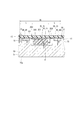
図1〜3に示すように、熱伝導部品40は、基板10の一方の面11側に設けられている。熱伝導部品40は、例えば銅等の電気伝導体により長方形の板状に形成されている。熱伝導部品40は、熱伝導率が所定値以上、例えば(300K)401W/(m・K)程度である。なお、熱伝導部品40は、比熱容量が例えば385×102J/(kg・K)程度である。本実施形態では、熱伝導部品40には、錫ニッケルめっきが施されている。これにより、熱伝導部品40は、耐腐食性、および、はんだ付け性が向上する。熱伝導部品40は、本実施形態では、7つ(41〜47)設けられている。
As shown in FIGS. 1 to 3, the heat conducting component 40 is provided on the one
熱伝導部品41は、半導体モジュール21と半導体モジュール22との間に設けられている。熱伝導部品41は、一方の面がプリント配線31とプリント配線32との間に対向または接するようにして設けられている。熱伝導部品41は、プリント配線31とプリント配線32との間にはんだ付けされている。熱伝導部品41は、長手方向が半導体モジュール21、22の封止体202の辺に概ね平行になるようにして設けられている。
The heat conducting component 41 is provided between the
熱伝導部品42は、半導体モジュール21と半導体モジュール23との間に設けられている。熱伝導部品42は、一方の面がプリント配線33に対向または接するようにして設けられている。熱伝導部品42は、プリント配線33にはんだ付けされている。熱伝導部品42は、長手方向が半導体モジュール21、23の封止体202の辺に概ね平行になるようにして設けられている。
The heat conducting component 42 is provided between the
熱伝導部品43は、半導体モジュール22と半導体モジュール24との間に設けられている。熱伝導部品43は、一方の面がプリント配線34に対向または接するようにして設けられている。熱伝導部品43は、プリント配線34にはんだ付けされている。熱伝導部品43は、長手方向が半導体モジュール22、24の封止体202の辺に概ね平行になるようにして設けられている。
The heat conducting component 43 is provided between the
熱伝導部品44は、半導体モジュール21の熱伝導部品41とは反対側に設けられている。熱伝導部品44は、一方の面がプリント配線31に対向または接するようにして設けられている。熱伝導部品44は、プリント配線31にはんだ付けされている。熱伝導部品44は、長手方向が半導体モジュール21の辺に概ね平行になるようにして設けられている。
The heat conducting component 44 is provided on the opposite side of the
熱伝導部品45は、半導体モジュール21の熱伝導部品42とは反対側に設けられている。熱伝導部品45は、一方の面がプリント配線31に対向または接するようにして設けられている。熱伝導部品45は、プリント配線31にはんだ付けされている。熱伝導部品45は、長手方向が半導体モジュール21の辺に概ね平行になるようにして設けられている。
The heat conducting component 45 is provided on the opposite side of the
熱伝導部品46は、半導体モジュール22の熱伝導部品41とは反対側に設けられている。熱伝導部品46は、一方の面がプリント配線32に対向または接するようにして設けられている。熱伝導部品46は、プリント配線32にはんだ付けされている。熱伝導部品46は、長手方向が半導体モジュール22の辺に概ね平行になるようにして設けられている。
The heat conducting component 46 is provided on the opposite side of the
熱伝導部品47は、半導体モジュール22の熱伝導部品43とは反対側に設けられている。熱伝導部品47は、一方の面がプリント配線32に対向または接するようにして設けられている。熱伝導部品47は、プリント配線32にはんだ付けされている。熱伝導部品47は、長手方向が半導体モジュール22の辺に概ね平行になるようにして設けられている。
The heat conducting component 47 is provided on the opposite side of the
このように、熱伝導部品41、42、43は、それぞれ、半導体モジュール21と半導体モジュール22との間、半導体モジュール21と半導体モジュール23との間、半導体モジュール22と半導体モジュール24との間に設けられている。すなわち、熱伝導部品40は、少なくとも一部が複数の半導体モジュール20の間に位置するよう設けられている。
Thus, the heat conducting components 41, 42, and 43 are provided between the
また、熱伝導部品41、44、45は、半導体モジュール21を囲むようにして設けられている。また、熱伝導部品41、46、47は、半導体モジュール22を囲むようにして設けられている。すなわち、熱伝導部品40は、少なくとも一部が半導体モジュール20を囲むようにして設けられている。
Further, the heat conducting components 41, 44 and 45 are provided so as to surround the
図2に示すように、半導体モジュール20の封止体202の長手方向の辺の長さをLとすると、熱伝導部品41、44、45は、半導体モジュール21の封止体202の外縁から所定距離Lの範囲R1内に位置するよう設けられている。同様に、熱伝導部品41、46、47は、半導体モジュール22の封止体202の外縁から所定距離Lの範囲R1内に位置するよう設けられている。また、同様に、熱伝導部品42は、半導体モジュール23の封止体202の外縁から所定距離Lの範囲R1内に位置するよう設けられている。また、同様に、熱伝導部品43は、半導体モジュール24の封止体202の外縁から所定距離Lの範囲R1内に位置するよう設けられている。
また、本実施形態では、熱伝導部品41〜47は、いずれも、長手方向の長さが半導体モジュール20の封止体202の長手方向の辺の長さLより長く形成されている。
As shown in FIG. 2, when the length of the side in the longitudinal direction of the sealing
In the present embodiment, all of the heat conducting components 41 to 47 are formed such that the length in the longitudinal direction is longer than the length L of the side in the longitudinal direction of the sealing
上述のように、本実施形態では、熱伝導部品40は、複数の半導体モジュール20の間、または、半導体モジュール20の周囲のように半導体モジュール20の近傍に設けられている。そのため、半導体モジュール20の熱は、熱伝導部品40に伝導する。
As described above, in the present embodiment, the heat conducting component 40 is provided in the vicinity of the
コンデンサ51は、本実施形態では、例えばアルミ電解コンデンサである。コンデンサ51は、例えば略円柱状に形成され、軸方向が基板10の面に対し垂直になるよう、基板10の一方の面11側に実装されている(図1参照)。コンデンサ51は、本実施形態では、3つ設けられている。
リレー55、56は、本実施形態では、例えば機械的に構成されるメカリレーである。リレー55、56は、例えば基板10の他方の面12側に実装されている。
In this embodiment, the
In the present embodiment, the
コイル57は、本実施形態では、例えばチョークコイルである。コイル57は、例えば矩形柱状となるよう形成され、高さ方向が基板10の面に対し垂直になるよう、基板10の一方の面11側に実装されている(図1参照)。
In this embodiment, the
制御部60は、例えばマイコン61、カスタムIC62を有している。マイコン61、カスタムIC62は、例えばCPU、ROM、RAMおよびI/O等を有する半導体パッケージである。制御部60は、リレー55、56、半導体モジュール20(21〜24)の作動を制御する。制御部60は、車両の各部に設けられたセンサ類からの信号等に基づき、半導体モジュール20の作動を制御することにより、モータ101の回転駆動を制御する。
マイコン61およびカスタムIC62は、図1に示すように、基板10の他方の面12側に実装されている。
ここで、半導体モジュール20、コンデンサ51、リレー55、56、コイル57、制御部60の電気的な接続について、図5に基づき説明する。
The
The
Here, the electrical connection of the
車両の電源であるバッテリ102の正側は、リレー55に接続している。リレー55は、制御部60によって制御され、オン作動またはオフ作動することにより、バッテリ102から電子制御ユニット1への電力の供給を許容または遮断する。すなわち、リレー55は、本実施形態では、電源リレーである。
The positive side of the
バッテリ102からの電力は、コイル57を経由して半導体モジュール20(21〜24)に供給される。コイル57は、バッテリ102から電子制御ユニット1を経由してモータ101へ供給される電力のノイズを除去する。
The electric power from the
車両のイグニッション電源106は、リレー55とコイル57との間、および、制御部60に接続されている。制御部60(マイコン61、カスタムIC62)は、イグニッション電源106からの電力により作動する。
The
図5に示すように、半導体モジュール21と半導体モジュール23とが直列に接続されており、半導体モジュール22と半導体モジュール24とが直列に接続されている。そして、半導体モジュール21および23の2つの半導体モジュールと、半導体モジュール22および24の2つの半導体モジュールと、が並列に接続されている。
As shown in FIG. 5, the
また、半導体モジュール21および23の2つの半導体モジュールの接続点と、半導体モジュール22および24の2つの半導体モジュールの接続点との間に、リレー56およびモータ101が配置されている。また、コンデンサ51は、電源ラインとグランドとの間に並列に接続されている。コンデンサ51は、半導体モジュール20(21〜24)のオン/オフ作動(スイッチング作動)によって生じるサージ電圧を抑制する。
In addition, the
上述の構成により、例えば半導体モジュール21および24がオンとなり半導体モジュール22および23がオフになると、電流は、半導体モジュール21、リレー56、モータ101、半導体モジュール24の順に流れる。一方、半導体モジュール22および23がオンとなり半導体モジュール21および24がオフになると、電流は、半導体モジュール22、モータ101、リレー56、半導体モジュール23の順に流れる。モータ101は直流モータであるため、このようにして各半導体モジュール20(21〜24)がオン/オフに制御されることで、モータ101が回転駆動される。各半導体モジュール20(21〜24)の端子205には、制御部60(カスタムIC62)からの信号線が接続されている。つまり、制御部60は、半導体モジュール20のスイッチング作動を制御することで、モータ101の回転駆動を制御する。
With the above configuration, for example, when the
ここで、リレー56は、制御部60によって制御され、オン作動またはオフ作動することにより、バッテリ102からモータ101への電力の供給を許容または遮断する。すなわち、リレー56は、本実施形態では、モータリレーである。
Here, the
半導体モジュール20のスイッチング作動時、半導体モジュール20、コンデンサ51、リレー55、56、コイル57には比較的大きな電流が流れるため、半導体モジュール20のスイッチング素子201、コンデンサ51、リレー55、56、コイル57は、発熱し、比較的高い温度になる。ここで、半導体モジュール20は、作動時の発熱量が所定値以上の部品であり、特許請求の範囲における「発熱部品」に対応している。
During the switching operation of the
ヒートシンク70は、例えばアルミ等の金属により形成されている。ヒートシンク70は、本体71、柱状部72、および、ねじ73等を有している。本体71は、例えば矩形の板状に形成されている。ヒートシンク70は、本体71の一方の面701が基板10の一方の面11に対向するよう設けられている(図3参照)。
なお、ヒートシンク70は、比熱容量が例えば900×102J/(kg・K)程度である。また、ヒートシンク70は、熱伝導率が例えば(300K)237W/(m・K)程度である。
ヒートシンク70の本体71の一方の面701と基板10の一方の面11との間には、所定の隙間が形成されている。
The
The
A predetermined gap is formed between one
本体71の一方の面701には、他方の面702側、すなわち、基板10とは反対側へ凹む凹部である特定凹部711が形成されている。特定凹部711は、半導体モジュール20に対応する位置に形成されている。特定凹部711は、半導体モジュール20の封止体202の形状に対応するよう矩形状に形成されている。なお、特定凹部711は、封止体202よりも大きく形成されている。特定凹部711は、半導体モジュール21〜24のそれぞれに対応するよう4つ形成されている。
On one
図3に示すように、本実施形態では、半導体モジュール20の封止体202とヒートシンク70の特定凹部711との距離d1は、熱伝導部品40とヒートシンク70の一方の面701との距離d2以下に設定されている。本実施形態では、d1は、d2より小さく設定されている。そのため、例えば振動または外部からの力等によりヒートシンク70と基板10とが近付いたとしても、半導体モジュール20の封止体202とヒートシンク70とが当接することにより、ヒートシンク70と熱伝導部品40との接触を確実に抑制することができる。これにより、熱伝導部品40が基板10に対し位置ずれしたり基板10から脱落したりするのを確実に抑制することができる。
As shown in FIG. 3, in this embodiment, the distance d1 between the sealing
また、本実施形態のように、熱伝導部品40が電気伝導体により形成され、プリント配線30により半導体モジュール20に電気的に接続されている場合、ヒートシンク70が熱伝導部品40に接触すると、ヒートシンク70と熱伝導部品40との間が短絡するおそれがある。しかしながら、本実施形態では、上述の設定により、ヒートシンク70と熱伝導部品40との接触を抑制できるため、ヒートシンク70と熱伝導部品40との間の短絡についても抑制することができる。
柱状部72は、本体71から基板10に向かって略円柱状に延びるよう形成されている。本実施形態では、柱状部72は、基板10の4つの角部を含む所定の箇所に対応するよう形成されている(図1参照)。
Further, when the heat conducting component 40 is formed of an electric conductor and is electrically connected to the
The
基板10は、4つの角部を含む所定の箇所にねじ穴13を有している。ねじ73は、ねじ穴13に通され、ヒートシンク70の柱状部72にねじ込まれている。これにより、基板10は、ヒートシンク70に対する位置が安定する。
図1に示すように、柱状部72の直径をMとすると、熱伝導部品46、47は、一部が、柱状部72の外壁から所定距離Mの範囲R2内に位置するよう設けられている。
The
As shown in FIG. 1, assuming that the diameter of the
熱伝導部材75は、本実施形態では、例えば放熱グリスである。放熱グリスは、例えばシリコンを基材とする熱抵抗の小さなゲル状の部材である。熱伝導部材75は、基板10の一方の面11とヒートシンク70の一方の面701との間において、基板10、半導体モジュール20、プリント配線30、熱伝導部品40、ヒートシンク70に接するよう設けられている。これにより、熱伝導部材75は、半導体モジュール20および熱伝導部品40からの熱をヒートシンク70に伝導することができる。したがって、半導体モジュール20および熱伝導部品40からの熱を、熱伝導部材75およびヒートシンク70を経由して放熱することができる。
In the present embodiment, the
なお、本実施形態では、半導体モジュール20の端子203、204と熱伝導部品40とが、プリント配線30により接続されているため、半導体モジュール20のスイッチング素子201からの熱は、端子203、204およびプリント配線30を経由して熱伝導部品40に速やかに伝導する。そのため、半導体モジュール20からの熱を、プリント配線30、熱伝導部品40、熱伝導部材75およびヒートシンク70を経由して速やかに放熱することができる。
In the present embodiment, since the
図1に示すように、コネクタ80は、コネクタ本体800、給電端子81〜84、信号端子85を有している。コネクタ本体800は、例えば樹脂により矩形の筒状に形成されている。コネクタ本体800は、基板10の外縁部に設けられている。
給電端子81〜84、信号端子85は、例えば銅等の電気伝導体により形成されている。給電端子81〜84、信号端子85は、コネクタ本体800にインサート成形されている。
As shown in FIG. 1, the
The
給電端子81は、基板10上のプリント配線(図示せず)にはんだ付けされており、リレー55およびコイル57を経由して半導体モジュール21、22の端子203、すなわち、プリント配線31、32に電気的に接続している。給電端子82は、基板10上のプリント配線にはんだ付けされており、半導体モジュール23、24の端子204に電気的に接続している。
The
給電端子83は、基板10上のプリント配線にはんだ付けされており、半導体モジュール21の端子204および半導体モジュール23の端子203、すなわち、プリント配線33に電気的に接続している。給電端子84は、基板10上のプリント配線にはんだ付けされており、半導体モジュール22の端子204および半導体モジュール24の端子203、すなわち、プリント配線34に電気的に接続している。
The power supply terminal 83 is soldered to the printed wiring on the
信号端子85は、基板10上のプリント配線にはんだ付けされており、制御部60(マイコン61、カスタムIC62)に電気的に接続されている。信号端子85には、制御部60を介してモータ101を制御するための信号である操舵トルク信号および車速信号等が流れる。
モータ101が作動(回転)するとき、給電端子81〜84には、モータ101へ供給する、比較的大きな電流が流れる。
本実施形態では、熱伝導部品44は、半導体モジュール21とコネクタ80の給電端子81、82との間に設けられている。
The
When the
In the present embodiment, the heat conducting component 44 is provided between the
図1に示すように、基板10に直交する仮想平面VP1で基板10を2つの領域T1、T2に分けたとき、半導体モジュール20および給電端子81〜84は一方の領域T1側に設けられており、制御部60(マイコン61、カスタムIC62)および信号端子85は他方の領域T2側に設けられている。
As shown in FIG. 1, when the
コネクタ80には、ハーネス103が接続される(図4参照)。ハーネス103の導線104は、バッテリ102の正側とコネクタ80の給電端子81とを電気的に接続する。また、ハーネス103の導線105は、モータ101の巻線端子とコネクタ80の給電端子83、84とを電気的に接続する。すなわち、給電端子83、84は、モータ端子である。
次に、本実施形態の電子制御ユニット1の作動について説明する。
A
Next, the operation of the electronic control unit 1 of the present embodiment will be described.
車両の運転者がイグニッションスイッチをオンすると、イグニッション電源106から電子制御ユニット1に電力が供給され、電子制御ユニット1が起動する。電子制御ユニット1が起動すると、制御部60は、リレー55、56をオン作動させる。これにより、バッテリ102からモータ101への電力の供給が許容された状態となる。
When the driver of the vehicle turns on the ignition switch, electric power is supplied from the
制御部60は、イグニッションスイッチがオンの間、操舵トルク信号および車速信号等に基づき、半導体モジュール20(21〜24)のスイッチング作動を制御することにより、モータ101の回転駆動を制御する。これにより、モータ101からアシストトルクが出力され、運転者による操舵が補助される。
The
本実施形態では、制御部60が半導体モジュール20(21〜24)のスイッチング作動を制御することでモータ101の回転駆動を制御するとき、半導体モジュール20、コンデンサ51、リレー55、56、コイル57には比較的大きな電流が流れるため、半導体モジュール20、コンデンサ51、リレー55、56、コイル57は発熱し、比較的高い温度になる。なお、半導体モジュール20の熱の一部は、プリント配線30または熱伝導部材75を経由して熱伝導部品40に導かれる。
半導体モジュール20(21〜24)および熱伝導部品40の熱は、熱伝導部材75を経由してヒートシンク70に導かれる。
In the present embodiment, when the
The heat of the semiconductor module 20 (21 to 24) and the heat conducting component 40 is guided to the
このように、本実施形態では、電子制御ユニット1の作動時、半導体モジュール20(21〜24)および熱伝導部品40の熱をヒートシンク70に効果的に導くことができる。よって、発熱部品である半導体モジュール20(21〜24)、および、熱伝導部品40の熱を効果的に放熱することができる。
以上説明したように、(1)本実施形態の電子制御ユニット1は、モータ101を制御する電子制御ユニットであって、基板10と半導体モジュール20と熱伝導部品40と制御部60とを備えている。
半導体モジュール20は、基板10の一方の面11側に複数設けられ、作動時に発熱する。
As described above, in the present embodiment, the heat of the semiconductor module 20 (21 to 24) and the heat conducting component 40 can be effectively guided to the
As described above, (1) the electronic control unit 1 of the present embodiment is an electronic control unit that controls the
A plurality of
熱伝導部品40は、熱伝導率が所定値以上の材料により形成され、少なくとも一部(41、42、43)が複数の半導体モジュール20の間に位置するよう基板10の一方の面11側に設けられている。
制御部60は、基板10に設けられ、半導体モジュール20の作動を制御することでモータ101を制御可能である。
本実施形態では、熱伝導部品40の少なくとも一部(41、42、43)が、複数の半導体モジュール20の間に位置するよう設けられている。そのため、半導体モジュール20の熱は、熱伝導部品40に伝導する。これにより、半導体モジュール20の温度が過度に上昇するのを抑制することができる。また、熱伝導部品40は、少なくとも一部が複数の半導体モジュール20の間に位置するため、各半導体モジュール20間の熱干渉を抑制することができる。
The heat conducting component 40 is made of a material having a heat conductivity equal to or higher than a predetermined value, and at least a part (41, 42, 43) is located on one
The
In the present embodiment, at least a part (41, 42, 43) of the heat conducting component 40 is provided so as to be positioned between the plurality of
また、(2)本実施形態では、熱伝導部品40は、少なくとも一部(41〜47)が半導体モジュール20を囲むようにして設けられている。そのため、半導体モジュール20の熱を、熱伝導部品40により効果的に伝導させることができる。
(2) In the present embodiment, the heat conducting component 40 is provided so that at least a part (41 to 47) surrounds the
また、(3)本実施形態では、基板10の一方の面11に設けられ、半導体モジュール20に電気的に接続しているプリント配線30をさらに備えている。熱伝導部品40は、プリント配線30に接している。そのため、半導体モジュール20からの熱を、プリント配線30を経由して熱伝導部品40に速やかに伝導させることができる。
(3) In the present embodiment, the printed circuit board 30 further includes a printed wiring 30 provided on the one
また、(5)本実施形態では、基板10の一方の面11側に設けられ、半導体モジュール20および熱伝導部品40からの熱を放熱可能なヒートシンク70をさらに備えている。これにより、半導体モジュール20および熱伝導部品40の温度上昇をより効果的に抑えることができる。
Moreover, (5) In this embodiment, the
また、(6)本実施形態では、基板10の一方の面11とヒートシンク70との間に設けられ、半導体モジュール20および熱伝導部品40からの熱をヒートシンク70に伝導可能な熱伝導部材75をさらに備えている。これにより、半導体モジュール20および熱伝導部品40の熱を効果的に放熱し、半導体モジュール20および熱伝導部品40の温度上昇をより一層効果的に抑えることができる。
(6) In the present embodiment, the
また、(7)本実施形態では、ヒートシンク70は、基板10に向かって延びるよう形成された柱状部72を有している。熱伝導部品40は、少なくとも一部(46、47の一部)が柱状部72から所定距離Mの範囲R2内に位置するよう設けられている。なお、本実施形態では、所定距離Mは、柱状部72の直径と同じである。このように、熱伝導部品40の少なくとも一部が柱状部72の近傍に位置しているため、半導体モジュール20および熱伝導部品40の熱を、柱状部72に速やかに伝導させることができる。これにより、半導体モジュール20および熱伝導部品40の熱を速やかに放熱することができる。
(7) In the present embodiment, the
また、(8)本実施形態では、半導体モジュール20とヒートシンク70との距離d1は、熱伝導部品40とヒートシンク70との距離d2以下に設定されている。そのため、例えば振動または外部からの力等によりヒートシンク70と基板10とが近付いたとしても、半導体モジュール20とヒートシンク70とが当接することにより、ヒートシンク70から熱伝導部品40に対し大きな力が作用するのを抑制することができる。これにより、熱伝導部品40が基板10に対し位置ずれしたり基板10から脱落したりするのを抑制することができる。したがって、半導体モジュール20に対する熱伝導部品40の位置が安定し、半導体モジュール20からの熱を効果的に放熱することができる。
In the present embodiment, the distance d1 between the
また、(9)本実施形態では、半導体モジュール20とヒートシンク70との距離d1は、熱伝導部品40とヒートシンク70との距離d2より小さく設定されている。そのため、例えば振動または外部からの力等によりヒートシンク70と基板10とが近付いたとしても、半導体モジュール20の封止体202とヒートシンク70とが当接することにより、ヒートシンク70と熱伝導部品40との接触を確実に抑制することができる。これにより、熱伝導部品40が基板10に対し位置ずれしたり基板10から脱落したりするのを確実に抑制することができる。
(9) In the present embodiment, the distance d1 between the
また、(10)本実施形態は、コネクタ80をさらに備えている。
コネクタ80は、基板10に設けられ、半導体モジュール20を経由してモータ101へ供給される電流が流れる給電端子81〜84、ならびに、制御部60を介してモータ101を制御するための信号が流れる信号端子85を有している。
(10) The present embodiment further includes a
The
熱伝導部品40は、少なくとも一部(44)が半導体モジュール20(21)とコネクタ80の給電端子81、82との間に位置するよう設けられている。これにより、半導体モジュール20(21)とコネクタ80の給電端子81、82との間の熱干渉を抑制することができる。
The heat conducting component 40 is provided so that at least a part (44) is positioned between the semiconductor module 20 (21) and the
また、(11)本実施形態では、基板10に直交する仮想平面VP1で基板10を2つの領域T1、T2に分けたとき、半導体モジュール20および給電端子81〜84は一方の領域T1側に設けられており、制御部60および信号端子85は他方の領域T2側に設けられている。これにより、領域T1と領域T2との間の熱干渉を抑制できるとともに、モータ101作動時の電源ノイズが制御部60または信号端子85に影響するのを抑制することができる。そのため、モータ101を精度よく制御することができる。
(11) In the present embodiment, when the
また、(12)本実施形態では、電動パワーステアリング装置100は、上記電子制御ユニット1と、電子制御ユニット1により制御され、運転者による操舵を補助するアシストトルクを出力可能なモータ101と、を備えている。本実施形態の電子制御ユニット1は、半導体モジュール20の温度上昇を抑えつつ、各半導体モジュール20間の熱干渉を抑制可能なため、大きな電流が流れることで発熱量が大きくなる電動パワーステアリング装置100の電子制御ユニット1として用いるのに好適である。
(12) In the present embodiment, the electric
(第2実施形態)
本発明の第2実施形態による電子制御ユニットの一部を図6に示す。第2実施形態は、熱伝導部品40の数が第1実施形態と異なる。
第2実施形態では、第1実施形態で示した熱伝導部品44、45、46、47を備えていない。
第2実施形態は、上述した点以外の構成は、第1実施形態と同様である。
(Second Embodiment)
A part of the electronic control unit according to the second embodiment of the present invention is shown in FIG. The second embodiment is different from the first embodiment in the number of heat conducting components 40.
In the second embodiment, the heat conducting parts 44, 45, 46, 47 shown in the first embodiment are not provided.
The second embodiment is the same as the first embodiment except for the points described above.
以上説明したように、(1)本実施形態では、熱伝導部品40は、少なくとも一部(41、42、43)が複数の半導体モジュール20の間に位置するよう設けられている。これにより、第1実施形態と同様、半導体モジュール20の温度が過度に上昇するのを抑制することができる。また、各半導体モジュール20間の熱干渉を抑制することができる。
As described above, (1) in the present embodiment, the heat conducting component 40 is provided such that at least a part (41, 42, 43) is positioned between the plurality of
(第3実施形態)
本発明の第3実施形態による電子制御ユニットの一部を図7に示す。第3実施形態は、コンデンサ51の位置が第1実施形態と異なる。
(Third embodiment)
A part of the electronic control unit according to the third embodiment of the present invention is shown in FIG. The third embodiment is different from the first embodiment in the position of the
第3実施形態では、電子部品としてのコンデンサ51は、熱伝導部品44に対し半導体モジュール21とは反対側に設けられている。すなわち、熱伝導部品44は、半導体モジュール21とコンデンサ51との間に位置するよう設けられている。
第2実施形態は、上述した点以外の構成は、第1実施形態と同様である。
In the third embodiment, the
The second embodiment is the same as the first embodiment except for the points described above.
以上説明したように、(4)本実施形態は、基板10の一方の面11側に設けられるコンデンサ51を備えている。熱伝導部品40は、少なくとも一部(44)が半導体モジュール20とコンデンサ51との間に位置するよう設けられている。これにより、半導体モジュール21とコンデンサ51との間の熱干渉を抑制することができる。
As described above, (4) the present embodiment includes the
(第4実施形態)
本発明の第4実施形態による電子制御ユニットの一部を図8に示す。第4実施形態は、熱伝導部品40の形状等が第1実施形態と異なる。
第4実施形態では、熱伝導部品41と熱伝導部品45と熱伝導部品47とは、一体に略T字状に形成されている。
第4実施形態は、上述した点以外の構成は、第1実施形態と同様である。
本実施形態では、第1実施形態と比べ、熱伝導部品40の体積および表面積が大きいため、半導体モジュール20の温度上昇を抑えつつ、各半導体モジュール20間の熱干渉をより効果的に抑制可能である。
(Fourth embodiment)
A part of the electronic control unit according to the fourth embodiment of the present invention is shown in FIG. The fourth embodiment is different from the first embodiment in the shape of the heat conducting component 40 and the like.
In the fourth embodiment, the heat conducting component 41, the heat conducting component 45, and the heat conducting component 47 are integrally formed in a substantially T shape.
The configuration of the fourth embodiment is the same as that of the first embodiment except for the points described above.
In the present embodiment, since the volume and surface area of the heat conducting component 40 are large compared to the first embodiment, it is possible to more effectively suppress the thermal interference between the
(他の実施形態)
本発明の他の実施形態では、熱伝導部品は、熱伝導率が所定値以上であれば、例えばカーボン等、どのような材料で形成されていてもよい。また、熱伝導部品は、電気伝導体に限らず、例えば窒化アルミニウムや窒化ケイ素等の絶縁体により形成されていてもよい。また、熱伝導部品は、基板上の配線に接していなくてもよい。また、熱伝導部品は、発熱部品に接していてもよい。また、熱伝導部品は、矩形状に限らず、多角形状、円形等、どのような形状に形成されていてもよい。また、熱伝導部品には、めっきが施されていなくてもよい。
また、上述の実施形態では、発熱部品の封止体の長手方向の辺の長さをLとすると、熱伝導部品(41、44、45)が、発熱部品(21)の封止体の外縁から所定距離Lの範囲R1内に位置するよう設けられる例を示した。これに対し、本発明の他の実施形態では、熱伝導部品(41、44、45)は、一部が範囲R1外に位置するよう設けられていてもよい。また、熱伝導部品(41、44、45)は、範囲R1内に設けられていなくてもよい。ただし、発熱部品からの熱を、熱伝導部品を経由して効果的に放熱するには、熱伝導部品は発熱部品の近傍に設けることが望ましい。また、発熱部品の封止体は、矩形状に限らず、多角形状、円形等、どのような形状に形成されていてもよい。
また、上述の実施形態では、4つの発熱部品を、仮想の長方形の頂点上に位置するよう基板に配置する例を示した(図2等参照)。これに対し、本発明の他の実施形態では、4つの発熱部品を、例えば仮想の正方形、平行四辺形、菱形、台形、または、その他四角形の頂点上に位置するよう基板に配置することとしてもよい。
また、本発明の他の実施形態では、発熱部品は、4つに限らず、2つ、3つ、または、5つ以上設けられていてもよい。この場合、発熱部品は、基板上にどのように配置してもよい。
(Other embodiments)
In another embodiment of the present invention, the heat conducting component may be formed of any material such as carbon as long as the heat conductivity is equal to or higher than a predetermined value. Further, the heat conducting component is not limited to an electric conductor, and may be formed of an insulator such as aluminum nitride or silicon nitride. Further, the heat conducting component may not be in contact with the wiring on the substrate. Further, the heat conducting component may be in contact with the heat generating component. In addition, the heat conducting component is not limited to a rectangular shape, and may be formed in any shape such as a polygonal shape or a circular shape. Further, the heat conductive component may not be plated.
Moreover, in the above-mentioned embodiment, when the length of the side in the longitudinal direction of the sealing body of the heat generating component is L, the heat conduction component (41, 44, 45) is the outer edge of the sealing body of the heat generating component (21). An example is shown in which it is provided within a range R1 of a predetermined distance L from the center. On the other hand, in other embodiment of this invention, heat conduction components (41, 44, 45) may be provided so that a part may be located outside the range R1. Further, the heat conducting components (41, 44, 45) may not be provided within the range R1. However, in order to effectively dissipate the heat from the heat generating component via the heat conductive component, it is desirable to provide the heat conductive component in the vicinity of the heat generating component. Moreover, the sealing body of the heat generating component is not limited to a rectangular shape, and may be formed in any shape such as a polygonal shape or a circular shape.
Further, in the above-described embodiment, an example in which four heat generating components are arranged on the substrate so as to be positioned on the top of a virtual rectangle has been shown (see FIG. 2 and the like). On the other hand, in another embodiment of the present invention, the four heat generating components may be arranged on the substrate so as to be positioned on the vertex of, for example, a virtual square, a parallelogram, a rhombus, a trapezoid, or other rectangles. Good.
In another embodiment of the present invention, the number of heat generating components is not limited to four, and two, three, or five or more may be provided. In this case, the heat generating component may be arranged in any manner on the substrate.
また、上述の実施形態では、放熱体の柱状部の直径をMとすると、熱伝導部品(46、47)は、一部が、柱状部の外壁から所定距離Mの範囲R2内に位置するよう設けられる例を示した。これに対し、本発明の他の実施形態では、熱伝導部品(46、47)は、範囲R2内に設けられていなくてもよい。ただし、発熱部品からの熱を、熱伝導部品および柱状部を経由して効果的に放熱するためには、熱伝導部品は、柱状部の近傍に設けることが望ましい。
また、本発明の他の実施形態では、放熱体の柱状部は、円柱状に限らず、例えば多角柱状等、どのような形状に形成されていてもよい。また、柱状部は、基板に固定されていなくてもよい。また、柱状部は、基板に接していなくてもよい。また、また、本発明の他の実施形態では、放熱体は、柱状部を有していなくてもよい。
また、本発明の他の実施形態では、熱伝導部材は、例えばシリコンを基材とする熱抵抗の小さなシート状の放熱シートであってもよい。また、本発明の他の実施形態では、熱伝導部材を備えなくてもよい。
Moreover, in the above-mentioned embodiment, when the diameter of the columnar part of the radiator is M, a part of the heat conducting component (46, 47) is located within a range R2 of a predetermined distance M from the outer wall of the columnar part. The example provided is shown. On the other hand, in other embodiment of this invention, the heat conductive components (46, 47) do not need to be provided in the range R2. However, in order to effectively dissipate heat from the heat generating component via the heat conductive component and the columnar portion, it is desirable that the heat conductive component is provided in the vicinity of the columnar portion.
Moreover, in other embodiment of this invention, the columnar part of a heat radiator is not restricted to a column shape, For example, you may form in what kind of shapes, such as a polygonal column shape. Further, the columnar part may not be fixed to the substrate. Further, the columnar part may not be in contact with the substrate. Moreover, in other embodiment of this invention, the heat radiator does not need to have a columnar part.
In another embodiment of the present invention, the heat conduction member may be a sheet-like heat radiation sheet having, for example, silicon as a base material and low thermal resistance. Moreover, in other embodiment of this invention, it is not necessary to provide a heat conductive member.
また、上述の実施形態では、発熱部品と放熱体との距離は、熱伝導部品と放熱体との距離より小さく設定されている例を示した。これに対し、本発明の他の実施形態では、発熱部品と放熱体との距離は、熱伝導部品と放熱体との距離以下に設定してもよい。また、本発明の他の実施形態では、発熱部品と放熱体との距離は、熱伝導部品と放熱体との距離に関係なく、どのように設定されていてもよい。ただし、熱伝導部品が電気伝導体により形成されている場合、発熱部品と放熱体との距離は、熱伝導部品と放熱体との距離より小さく設定されていることが望ましい。また、放熱体は、アルミに限らず、鉄、銅、窒化アルミニウムまたは窒化ケイ素等の熱伝導率が所定値以上の材料により形成されていてもよい。また、本発明の他の実施形態では、放熱体を備えていなくてもよい。
また、本発明の他の実施形態では、発熱部品の封止体は、樹脂に限らず、窒化アルミニウムや窒化ケイ素等の絶縁体により形成されていてもよい。また、発熱素子は、封止体から一部が露出していてもよい。
本発明による電子制御ユニットは、電動パワーステアリング装置に限らず、他の装置のモータ等、電動機器の駆動を制御するのに用いてもよい。
このように、本発明は、上記実施形態に限定されるものではなく、その要旨を逸脱しない範囲で種々の形態で実施可能である。
Moreover, in the above-described embodiment, the example in which the distance between the heat generating component and the heat radiator is set smaller than the distance between the heat conducting component and the heat radiator is described. On the other hand, in other embodiment of this invention, you may set the distance of a heat-emitting component and a heat radiator to below the distance of a heat conductive component and a heat radiator. In another embodiment of the present invention, the distance between the heat generating component and the heat radiating member may be set in any way regardless of the distance between the heat conducting component and the heat radiating member. However, when the heat conducting component is formed of an electric conductor, the distance between the heat generating component and the heat radiating body is preferably set smaller than the distance between the heat conducting component and the heat radiating member. The heat radiator is not limited to aluminum, and may be formed of a material having a thermal conductivity of a predetermined value or more, such as iron, copper, aluminum nitride, or silicon nitride. Moreover, in other embodiment of this invention, it is not necessary to provide the heat radiator.
In another embodiment of the present invention, the sealing body of the heat generating component is not limited to resin, and may be formed of an insulator such as aluminum nitride or silicon nitride. Further, the heating element may be partially exposed from the sealing body.
The electronic control unit according to the present invention is not limited to the electric power steering apparatus, and may be used to control driving of an electric device such as a motor of another apparatus.
Thus, the present invention is not limited to the above-described embodiment, and can be implemented in various forms without departing from the gist thereof.
1 電子制御ユニット、10 基板、20 半導体モジュール(発熱部品)、40 熱伝導部品、60 制御部、101 モータ(制御対象) DESCRIPTION OF SYMBOLS 1 Electronic control unit, 10 Board | substrate, 20 Semiconductor module (heat-generating component), 40 Thermal conduction component, 60 Control part, 101 Motor (control object)
Claims (18)
基板(10)と、
前記基板の一方の面(11)側に複数設けられ、作動時に発熱する発熱部品(20)と、
熱伝導率が所定値以上の材料により形成され、少なくとも一部が複数の前記発熱部品の間に位置するよう前記基板の一方の面側に設けられた熱伝導部品(40)と、
前記基板に設けられ、前記発熱部品の作動を制御することで前記制御対象を制御可能な制御部(60)と、
を備え、
前記発熱部品および前記熱伝導部品は、前記基板上の一方の領域(T1)に設けられており、
前記制御部は、前記基板上の前記一方の領域とは反対側の領域である他方の領域(T2)に設けられており、
前記基板に設けられ、前記発熱部品を経由して前記制御対象へ供給される電流が流れる給電端子(81、82、83、84)、ならびに、前記制御部を介して前記制御対象を制御するための信号が流れる信号端子(85)を有するコネクタ(80)をさらに備え、
前記熱伝導部品は、少なくとも一部が前記発熱部品と前記コネクタとの間に位置するよう設けられており、
前記基板に直交する仮想平面(VP1)で前記基板を2つの領域(T1、T2)に分けたとき、前記発熱部品および前記給電端子は一方の領域(T1)側に設けられており、前記制御部および前記信号端子は他方の領域(T2)側に設けられている電子制御ユニット(1)。 An electronic control unit (1) for controlling a controlled object (101),
A substrate (10);
A plurality of heat generating components (20) provided on one side (11) side of the substrate and generating heat during operation;
A heat-conducting component (40) formed of a material having a thermal conductivity of a predetermined value or more and provided on one surface side of the substrate so that at least a portion is located between the plurality of heat-generating components;
A control unit (60) provided on the substrate and capable of controlling the control object by controlling the operation of the heat generating component;
With
The heat generating component and the heat conducting component are provided in one region (T1) on the substrate,
The control unit is provided in the other region (T2) which is a region opposite to the one region on the substrate ,
To control the control target via the power supply terminals (81, 82, 83, 84) provided on the substrate and through which the current supplied to the control target via the heat generating component flows, and the control unit A connector (80) having a signal terminal (85) through which a signal of
The heat conducting component is provided so that at least a part is located between the heat generating component and the connector,
When the substrate is divided into two regions (T1, T2) on a virtual plane (VP1) orthogonal to the substrate, the heat generating component and the power supply terminal are provided on one region (T1) side, and the control And the signal terminal are provided on the other region (T2) side electronic control unit (1).
基板(10)と、
前記基板の一方の面(11)側に複数設けられ、作動時に発熱する発熱部品(20)と、
熱伝導率が所定値以上の材料により形成され、少なくとも一部が複数の前記発熱部品の間に位置するよう前記基板の一方の面側に設けられた熱伝導部品(40)と、
前記基板に設けられ、前記発熱部品の作動を制御することで前記制御対象を制御可能な制御部(60)と、
を備え、
前記発熱部品および前記熱伝導部品は、前記基板上の一方の領域(T1)に設けられており、
前記制御部は、前記基板上の前記一方の領域とは反対側の領域である他方の領域(T2)に設けられており、
前記発熱部品は、少なくとも4つが並んで配置されており、
並んで配置された4つの前記発熱部品を時計回りに第1発熱部品(21)、第2発熱部品(22)、第3発熱部品(24)、第4発熱部品(23)とすると、前記熱伝導部品は、少なくとも、前記第1発熱部品と前記第2発熱部品との間に設けられた第1熱伝導部品(41)、前記第2発熱部品と前記第3発熱部品との間に設けられた第2熱伝導部品(43)、および、前記第1発熱部品と前記第4発熱部品との間に設けられた第3熱伝導部品(42)により構成されており、
前記第1発熱部品、前記第2発熱部品は、互いに並列接続された半導体モジュールであり、
前記第3発熱部品、前記第4発熱部品は、互いに並列接続された半導体モジュールであり、
前記第1発熱部品、前記第2発熱部品と前記第3発熱部品、前記第4発熱部品との間に前記制御対象が接続されており、
前記熱伝導部品は、前記第3発熱部品と前記第4発熱部品との間には設けられていない電子制御ユニット(1)。 An electronic control unit (1) for controlling a controlled object (101),
A substrate (10);
A plurality of heat generating components (20) provided on one side (11) side of the substrate and generating heat during operation;
A heat-conducting component (40) formed of a material having a thermal conductivity of a predetermined value or more and provided on one surface side of the substrate so that at least a portion is located between the plurality of heat-generating components;
A control unit (60) provided on the substrate and capable of controlling the control object by controlling the operation of the heat generating component;
With
The heat generating component and the heat conducting component are provided in one region (T1) on the substrate,
The control unit is provided in the other region (T2) which is a region opposite to the one region on the substrate,
At least four of the heat generating parts are arranged side by side,
When the four heat generating components arranged side by side are defined as a first heat generating component (21), a second heat generating component (22), a third heat generating component (24), and a fourth heat generating component (23) in the clockwise direction, The conductive component is provided at least between the first heat conductive component (41) provided between the first heat generating component and the second heat generating component, and between the second heat generating component and the third heat generating component. The second heat conducting component (43) and the third heat conducting component (42) provided between the first heat generating component and the fourth heat generating component ,
The first heat generating component and the second heat generating component are semiconductor modules connected in parallel to each other,
The third heat generating component and the fourth heat generating component are semiconductor modules connected in parallel to each other,
The control object is connected between the first heat generating component, the second heat generating component, the third heat generating component, and the fourth heat generating component,
The electronic control unit (1) , wherein the heat conducting component is not provided between the third heat generating component and the fourth heat generating component .
基板(10)と、
前記基板の一方の面(11)側に複数設けられ、作動時に発熱する発熱部品(20)と、
熱伝導率が所定値以上の材料により形成され、少なくとも一部が複数の前記発熱部品の間に位置するよう前記基板の一方の面側に設けられた熱伝導部品(40)と、
前記基板に設けられ、前記発熱部品の作動を制御することで前記制御対象を制御可能な制御部(60)と、
を備え、
前記基板の一方の面に、複数の前記発熱部品のうち第1の発熱部品(21)に対応する第1のプリント配線(31)と、複数の前記発熱部品のうち第2の発熱部品(23)に対応する第2のプリント配線(33)とが隣り合うようにして配置されており、
前記熱伝導部品は、前記第1のプリント配線に位置する第1の熱伝導部品(41、44、45)、および、前記第2のプリント配線に位置する第2の熱伝導部品(42)を有し、
前記第1の熱伝導部品および前記第2の熱伝導部品は、前記発熱部品を囲むようにして設けられている電子制御ユニット(1)。 An electronic control unit (1) for controlling a controlled object (101),
A substrate (10);
A plurality of heat generating components (20) provided on one side (11) side of the substrate and generating heat during operation;
A heat-conducting component (40) formed of a material having a thermal conductivity of a predetermined value or more and provided on one surface side of the substrate so that at least a portion is located between the plurality of heat-generating components;
A control unit (60) provided on the substrate and capable of controlling the control object by controlling the operation of the heat generating component;
With
The first printed wiring (31) corresponding to the first heat generating component (21) among the plurality of heat generating components and the second heat generating component (23 among the plurality of heat generating components) are provided on one surface of the substrate. ) Is arranged adjacent to the second printed wiring (33) corresponding to
The heat conducting parts include a first heat conducting part (41, 44, 45) located in the first printed wiring and a second heat conducting part (42) located in the second printed wiring. Have
The electronic control unit (1), wherein the first heat conductive component and the second heat conductive component are provided so as to surround the heat generating component.
前記第1の発熱部品の前記第1端子は、前記第1のプリント配線に接続され、
前記第1の発熱部品の前記第2端子は、前記第2のプリント配線に接続され、
前記第2の発熱部品の前記第1端子は、前記第2のプリント配線に接続されている請求項6に記載の電子制御ユニット。 The heat generating component is a semiconductor module, and is electrically connected to a first terminal (203) electrically connected to a drain, a second terminal (204) electrically connected to a source, and a gate. A third terminal (205);
The first terminal of the first heat-generating component is connected to the first printed wiring;
The second terminal of the first heat generating component is connected to the second printed wiring,
The electronic control unit according to claim 6 , wherein the first terminal of the second heat-generating component is connected to the second printed wiring.
前記熱伝導部品は、前記配線に接している請求項2〜8のいずれか一項に記載の電子制御ユニット。 A wiring (30) provided on one surface of the substrate and electrically connected to the heat-generating component;
The electronic control unit according to any one of claims 2 to 8 , wherein the heat conducting component is in contact with the wiring.
前記熱伝導部品は、少なくとも一部が前記発熱部品と前記電子部品との間に位置するよう設けられている請求項2〜9のいずれか一項に記載の電子制御ユニット。 An electronic component (51) provided on one surface side of the substrate;
The electronic control unit according to any one of claims 2 to 9 , wherein at least a part of the heat conducting component is provided between the heat generating component and the electronic component.
前記熱伝導部品は、少なくとも一部が前記柱状部から所定距離(M)の範囲(R2)内に位置するよう設けられている請求項11または12に記載の電子制御ユニット。 The radiator has a columnar portion (72) formed to extend toward the substrate,
The electronic control unit according to claim 11 or 12 , wherein at least a part of the heat conducting component is provided within a range (R2) of a predetermined distance (M) from the columnar part.
前記熱伝導部品は、少なくとも一部が前記発熱部品と前記コネクタとの間に位置するよう設けられている請求項2〜15のいずれか一項に記載の電子制御ユニット。 To control the control target via the power supply terminals (81, 82, 83, 84) provided on the substrate and through which the current supplied to the control target via the heat generating component flows, and the control unit A connector (80) having a signal terminal (85) through which a signal of
The electronic control unit according to any one of claims 2 to 15 , wherein at least a part of the heat conducting component is provided between the heat generating component and the connector.
前記電子制御ユニットにより制御され、運転者による操舵を補助するアシストトルクを出力可能な前記制御対象(101)と、
を備える電動パワーステアリング装置(100)。 Electronic control unit (1) according to any one of claims 1 to 17 ,
The control object (101) controlled by the electronic control unit and capable of outputting an assist torque for assisting steering by a driver;
An electric power steering apparatus (100) comprising:
Priority Applications (4)
| Application Number | Priority Date | Filing Date | Title |
|---|---|---|---|
| JP2016002869A JP6555134B2 (en) | 2016-01-08 | 2016-01-08 | Electronic control unit and electric power steering apparatus using the same |
| PCT/JP2016/087498 WO2017119264A1 (en) | 2016-01-08 | 2016-12-16 | Electronic control unit and electric power steering device using same |
| US16/067,971 US10674639B2 (en) | 2016-01-08 | 2016-12-16 | Electronic control unit and electric power steering device using the same |
| CN201680078549.XA CN108463883B (en) | 2016-01-08 | 2016-12-16 | Electronic control unit and electric power steering apparatus using the same |
Applications Claiming Priority (1)
| Application Number | Priority Date | Filing Date | Title |
|---|---|---|---|
| JP2016002869A JP6555134B2 (en) | 2016-01-08 | 2016-01-08 | Electronic control unit and electric power steering apparatus using the same |
Publications (3)
| Publication Number | Publication Date |
|---|---|
| JP2017123440A JP2017123440A (en) | 2017-07-13 |
| JP2017123440A5 JP2017123440A5 (en) | 2018-04-19 |
| JP6555134B2 true JP6555134B2 (en) | 2019-08-07 |
Family
ID=59274138
Family Applications (1)
| Application Number | Title | Priority Date | Filing Date |
|---|---|---|---|
| JP2016002869A Active JP6555134B2 (en) | 2016-01-08 | 2016-01-08 | Electronic control unit and electric power steering apparatus using the same |
Country Status (4)
| Country | Link |
|---|---|
| US (1) | US10674639B2 (en) |
| JP (1) | JP6555134B2 (en) |
| CN (1) | CN108463883B (en) |
| WO (1) | WO2017119264A1 (en) |
Families Citing this family (6)
| Publication number | Priority date | Publication date | Assignee | Title |
|---|---|---|---|---|
| JP6737221B2 (en) * | 2017-04-11 | 2020-08-05 | 株式会社デンソー | Electric power steering control device and electronic unit. |
| JP6838501B2 (en) * | 2017-06-14 | 2021-03-03 | 株式会社デンソー | Electronic control device and electric power steering device using this |
| JP7007131B2 (en) * | 2017-08-09 | 2022-01-24 | 澤藤電機株式会社 | Heat dissipation structure in circuit board equipment |
| JP7172471B2 (en) * | 2018-11-09 | 2022-11-16 | 住友電装株式会社 | Substrate structure |
| JP7160012B2 (en) * | 2019-10-03 | 2022-10-25 | 株式会社デンソー | electronic controller |
| TWI714479B (en) * | 2020-03-19 | 2020-12-21 | 車王電子股份有限公司 | Brushless motor assembly |
Family Cites Families (19)
| Publication number | Priority date | Publication date | Assignee | Title |
|---|---|---|---|---|
| JPH10322068A (en) * | 1997-05-16 | 1998-12-04 | Nippon Electric Ind Co Ltd | Mounting method of heat releasing element |
| JP2001068879A (en) * | 1999-08-26 | 2001-03-16 | Denso Corp | Control equipment |
| JP2004022983A (en) * | 2002-06-19 | 2004-01-22 | Mitsubishi Electric Corp | Semiconductor device |
| JP2006041199A (en) * | 2004-07-27 | 2006-02-09 | Matsushita Electric Works Ltd | Electronic device |
| JP2010245174A (en) | 2009-04-02 | 2010-10-28 | Denso Corp | Electronic control unit and method of manufacturing the same |
| JP5110049B2 (en) * | 2009-07-16 | 2012-12-26 | 株式会社デンソー | Electronic control device |
| JP5408502B2 (en) * | 2010-09-06 | 2014-02-05 | 株式会社デンソー | Electronic control unit |
| JP2013004953A (en) | 2011-06-22 | 2013-01-07 | Denso Corp | Electronic control device |
| CN102709262B (en) * | 2012-06-06 | 2015-09-30 | 华为技术有限公司 | Radiator and the circuit board being provided with this radiator of multi-chip common |
| JP6002473B2 (en) * | 2012-06-29 | 2016-10-05 | 日立アプライアンス株式会社 | Electronic equipment and power conditioner |
| JP5803856B2 (en) * | 2012-09-06 | 2015-11-04 | 株式会社デンソー | Electronic control unit |
| JP6177510B2 (en) * | 2012-09-13 | 2017-08-09 | 株式会社デンソー | Electronic control unit |
| JP5725055B2 (en) * | 2013-02-12 | 2015-05-27 | 株式会社デンソー | Electronic control unit |
| US9142477B2 (en) * | 2013-03-08 | 2015-09-22 | Kabushiki Kaisha Toshiba | Semiconductor module |
| US10269688B2 (en) * | 2013-03-14 | 2019-04-23 | General Electric Company | Power overlay structure and method of making same |
| JP6278695B2 (en) * | 2013-12-26 | 2018-02-14 | 株式会社デンソー | Electronic control unit and electric power steering apparatus using the same |
| JP5939246B2 (en) * | 2013-12-26 | 2016-06-22 | 株式会社デンソー | Electronic control unit |
| JP6418041B2 (en) * | 2015-04-06 | 2018-11-07 | 株式会社デンソー | Electronic control unit |
| JP6398849B2 (en) * | 2015-04-06 | 2018-10-03 | 株式会社デンソー | Electronic control unit |
-
2016
- 2016-01-08 JP JP2016002869A patent/JP6555134B2/en active Active
- 2016-12-16 WO PCT/JP2016/087498 patent/WO2017119264A1/en active Application Filing
- 2016-12-16 US US16/067,971 patent/US10674639B2/en active Active
- 2016-12-16 CN CN201680078549.XA patent/CN108463883B/en active Active
Also Published As
| Publication number | Publication date |
|---|---|
| JP2017123440A (en) | 2017-07-13 |
| CN108463883B (en) | 2021-12-03 |
| US10674639B2 (en) | 2020-06-02 |
| WO2017119264A1 (en) | 2017-07-13 |
| US20190014692A1 (en) | 2019-01-10 |
| CN108463883A (en) | 2018-08-28 |
Similar Documents
| Publication | Publication Date | Title |
|---|---|---|
| JP6555134B2 (en) | Electronic control unit and electric power steering apparatus using the same | |
| JP6278695B2 (en) | Electronic control unit and electric power steering apparatus using the same | |
| JP5408502B2 (en) | Electronic control unit | |
| JP6115465B2 (en) | Electronic control unit and electric power steering apparatus using the same | |
| JP5967071B2 (en) | Electronic control device and electric power steering device using the same | |
| JP2017123440A5 (en) | ||
| CN108476601B (en) | Electronic control unit and electric power steering apparatus using the same | |
| JP6468036B2 (en) | Electronic control unit | |
| JP2016197688A (en) | Electronic control device | |
| JP2017123439A5 (en) | ||
| CN111373525B (en) | Circuit structure and electrical junction box | |
| KR20180060572A (en) | Device package having heat dissipating member and the manufacturing method thereof | |
| JP6961902B2 (en) | Component mounts and electronic devices | |
| JP2009012631A (en) | Electric power steering device | |
| WO2018190289A1 (en) | Electric power-steering control device and electronic unit | |
| WO2020080248A1 (en) | Circuit structure and electrical junction box | |
| JP6131879B2 (en) | Electronic control unit and electric power steering apparatus using the same. | |
| JP2019197855A (en) | Circuit structure and electric connection box | |
| JP5454438B2 (en) | Semiconductor module | |
| JP2020013897A (en) | Substrate structure |
Legal Events
| Date | Code | Title | Description |
|---|---|---|---|
| A521 | Request for written amendment filed |
Free format text: JAPANESE INTERMEDIATE CODE: A523 Effective date: 20180308 |
|
| A621 | Written request for application examination |
Free format text: JAPANESE INTERMEDIATE CODE: A621 Effective date: 20180308 |
|
| A131 | Notification of reasons for refusal |
Free format text: JAPANESE INTERMEDIATE CODE: A131 Effective date: 20180814 |
|
| A521 | Request for written amendment filed |
Free format text: JAPANESE INTERMEDIATE CODE: A523 Effective date: 20181015 |
|
| A131 | Notification of reasons for refusal |
Free format text: JAPANESE INTERMEDIATE CODE: A131 Effective date: 20190108 |
|
| A521 | Request for written amendment filed |
Free format text: JAPANESE INTERMEDIATE CODE: A523 Effective date: 20190306 |
|
| TRDD | Decision of grant or rejection written | ||
| A01 | Written decision to grant a patent or to grant a registration (utility model) |
Free format text: JAPANESE INTERMEDIATE CODE: A01 Effective date: 20190611 |
|
| A61 | First payment of annual fees (during grant procedure) |
Free format text: JAPANESE INTERMEDIATE CODE: A61 Effective date: 20190624 |
|
| R151 | Written notification of patent or utility model registration |
Ref document number: 6555134 Country of ref document: JP Free format text: JAPANESE INTERMEDIATE CODE: R151 |
|
| R250 | Receipt of annual fees |
Free format text: JAPANESE INTERMEDIATE CODE: R250 |
|
| R250 | Receipt of annual fees |
Free format text: JAPANESE INTERMEDIATE CODE: R250 |