JP6553016B2 - Game machine - Google Patents
Game machine Download PDFInfo
- Publication number
- JP6553016B2 JP6553016B2 JP2016223814A JP2016223814A JP6553016B2 JP 6553016 B2 JP6553016 B2 JP 6553016B2 JP 2016223814 A JP2016223814 A JP 2016223814A JP 2016223814 A JP2016223814 A JP 2016223814A JP 6553016 B2 JP6553016 B2 JP 6553016B2
- Authority
- JP
- Japan
- Prior art keywords
- movable
- movable decorative
- decoration
- decorative body
- normal state
- Prior art date
- Legal status (The legal status is an assumption and is not a legal conclusion. Google has not performed a legal analysis and makes no representation as to the accuracy of the status listed.)
- Active
Links
Images


Description
本発明は、遊技媒体を用いた遊技を行うことができる遊技機に関する。 The present invention relates to a gaming machine capable of playing a game using a game medium.
遊技機として、例えば、前面に遊技球が流下可能な遊技領域を有する遊技盤を、枠体(四角く枠組みされた外枠および該外枠に設けられた本体枠など)に着脱可能に取り付けて構成されるパチンコ遊技機が知られている。こうした遊技機の中には、枠体に多数の発光部材等を設け、遊技機外観の装飾効果を高めて遊技興趣を向上させるものがある。 As a gaming machine, for example, a game board having a game area in which a game ball can flow down on the front side is detachably attached to a frame (a square framed outer frame and a main frame provided on the outer frame). Pachinko machines that are played are known. Some of these gaming machines are provided with a large number of light-emitting members and the like on the frame to enhance the decoration effect on the appearance of the gaming machine and improve the gaming fun.
しかしながら、近年では、上述のように枠体に発光部等を搭載するだけでは遊技者に意外性や驚きを与えることが困難となってきており、十分に遊技興趣を高められない虞があった。 However, in recent years, it has become difficult to give the player surprise and surprise simply by mounting the light-emitting part or the like on the frame as described above, and there is a possibility that the gaming interest cannot be sufficiently enhanced. .
本発明は、上記に鑑みなされたもので、その目的は、新たな装飾構成によって、従来に比して遊技興趣を高められる遊技機を提供することにある。 The present invention has been made in view of the above, and an object of the present invention is to provide a gaming machine capable of enhancing the gaming interest compared to the prior art by a new decoration configuration.
上記の目的を達成するため本発明は、
始動条件の成立に基づいて図柄の変動表示を行い、該変動表示の結果に基づいて遊技利益を付与する遊技機において、
前記図柄の変動表示が行われる図柄表示部と、
前記図柄表示部の上側で前方に突出して設けられた可動装飾演出部と、を備え、
前記可動装飾演出部は、
当該遊技機の外形の一部を構成し、特定装飾を有する装飾面部が下側に向いた通常状態と、該通常状態に比べて前記特定装飾を有する装飾面部が正面側に向いた上昇状態とに変化可能であり、前記通常状態から前記上昇状態に変化することで当該遊技機の外形に変化を与えるものであって、
前記通常状態では、前記特定装飾を有する装飾面部が下側を向きつつも前記特定装飾の少なくとも一部が遊技者から視認可能とされ、前記上昇状態では、前記特定装飾を有する装飾面部が正面側を向いて前記通常状態とは異なる態様で前記特定装飾が視認可能とされるものであり、
さらに、前記通常状態では、前記特定装飾を有する装飾面部とは別の装飾面部が正面側を向いて位置しており、該別の装飾面部は、前記可動装飾演出部が前記通常状態から前記上昇状態に変化することに伴って他の位置に移動するものであり、
さらに、前記図柄表示部を有する遊技盤と、
当該遊技機の前面側を構成し、前記遊技盤を視認可能にする窓部を有する前扉部と、を備え、
前記可動装飾演出部は、前記前扉部に設けられるものであり、
前記遊技盤に設けられ、前記可動装飾演出部とは異なる盤側装飾演出部をさらに備え、
前記可動装飾演出部が前記上昇状態になることに並行して前記盤側装飾演出部が動作可能に設けられ、前記可動装飾演出部および前記盤側装飾演出部が並行して動作する過程で一体的な装飾を創出可能である
ことを特徴とする。
また、前記前扉部に設けられ、透過性を有する透過部と、
前記可動装飾演出部が前記通常状態にあるときには、前記透過部を介して前記特定装飾を遊技者に視認可能にし、
前記可動装飾演出部が前記上昇状態にあるときには、前記透過部を介することなく、該透過部の上方で前記特定装飾を遊技者に直視可能にする
ことを特徴とする。
また、始動条件の成立に基づいて図柄の変動表示を行い、該変動表示の結果に基づいて遊技利益を付与する遊技機において、
前記図柄の変動表示が行われる図柄表示部を有する遊技盤と、
当該遊技機の前面側を構成し、前記遊技盤を視認可能にする窓部を有する前扉部と、
前記前扉部に形成された膨出部に設けられ、通常状態と、該通常状態よりも上昇した上昇状態とに変化可能な可動装飾演出部と、
前記前扉部に形成された膨出部に設けられ、透過性を有する透過部と、
を備え、
前記可動装飾演出部は、当該遊技機の外形の一部を構成する部材であり、前記通常状態から前記上昇状態に変化することで、当該遊技機の外形が変化するものであり、
前記膨出部は、前記可動装飾演出部の動作に要する開口を上面に有しており、
前記透過部は、前記開口よりも下方に設けられており、
前記可動装飾演出部が前記通常状態にあるときには、前記可動装飾演出部そのものが前記開口を塞ぐように配置されると共に、前記開口よりも下方に設けられる前記透過部を介して前記可動装飾演出部による装飾を遊技者に視認可能にし、
前記可動装飾演出部が前記上昇状態にあるときには、前記透過部を介することなく、前記膨出部の上方で前記可動装飾演出部による装飾を遊技者に直視可能にする
ことを特徴とする。
In order to achieve the above object, the present invention is
In a gaming machine that performs a variation display of a symbol based on the establishment of a start condition and grants a gaming profit based on the result of the variation display,
A symbol display unit on which the variable display of the symbol is performed;
A movable decorative effect part provided to project forward on the upper side of the symbol display part;
The movable decoration effect unit is
A normal state in which a decorative surface part having a specific decoration faces downward, constituting a part of the outer shape of the gaming machine, and a raised state in which the decorative surface part having the specific decoration faces the front side as compared to the normal state. Change to the outer shape of the gaming machine by changing from the normal state to the raised state,
In the normal state, at least a part of the specific decoration is visible from the player while the decorative surface having the specific decoration faces downward, and in the raised state, the decorative surface having the specific decoration is on the front side And the specific decoration is visible in a mode different from the normal state.
Furthermore, in the normal state, a decorative surface portion different from the decorative surface portion having the specific decoration faces the front side, and in the other decorative surface portion, the movable decorative effect portion rises from the normal state Move to another position as the state changes,
Furthermore, a game board having the symbol display part,
A front door portion having a window portion that constitutes a front side of the gaming machine and makes the gaming board visible; and
The movable decoration effect part is provided in the front door part,
The game board further includes a board-side decoration effect part provided on the game board and different from the movable decoration effect part,
The board side decoration effect part is provided so as to be operable in parallel with the movable decoration effect part being in the raised state, and the movable decoration effect part and the board side decoration effect part are integrally operated in parallel. It is characterized by being able to create a decorative decoration.
Further, a transmission part provided on the front door part and having transparency,
When the movable decoration effect part is in the normal state, the specific decoration is made visible to the player through the transparent part,
When the movable decoration effect part is in the raised state, the specific decoration can be directly viewed by the player above the transmission part without passing through the transmission part.
In addition, in the gaming machine which performs variable display of symbols based on the establishment of the start condition, and provides a gaming profit based on the result of the variable display,
A game board having a symbol display portion on which the symbol variation display is performed;
A front door portion having a window portion that constitutes a front side of the gaming machine and makes the gaming board visible;
A movable decoration effect part provided in the bulging part formed on the front door part and capable of changing between a normal state and a rising state which is higher than the normal state;
A permeable portion provided on the bulging portion formed on the front door portion and having permeability;
Equipped with
The movable decoration effect part is a member constituting a part of the outer shape of the gaming machine, and the outer shape of the gaming machine changes by changing from the normal state to the raised state.
The bulging part has an opening required for the operation of the movable decorative effect part on the upper surface,
The transmission part is provided below the opening,
When the movable decoration effect part is in the normal state, the movable decoration effect part itself is disposed so as to close the opening, and the movable decoration effect part is provided via the transmission part provided below the opening. Makes it possible for players to see the decoration
When the movable decoration effect part is in the raised state, the decoration by the movable decoration effect part can be directly viewed by the player above the bulging part without passing through the transmission part.
新たな装飾構成によって、従来に比して遊技興趣を高めることができる。 With the new decoration configuration, it is possible to enhance the game interest compared to the prior art.
以下に本発明の実施の形態を図面を参照しつつ説明する。
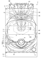
遊技機1は、枠体2と、枠体2に交換(着脱)可能に取り付けられた遊技盤3と、枠体2の前面を覆う開閉可能な前面部4と、を備えている。
Embodiments of the present invention will be described below with reference to the drawings.
The
[枠体]
枠体2は、木製又は合成樹脂製であって四角く枠組みされており、遊技場の島設備に取り付けられる。
[Frame]
The
[遊技盤]
遊技盤3は、透明な合成樹脂製の遊技基板5と、該遊技基板5の後面側に取り付けられた盤支持枠6と、該盤支持枠6に支持される第1〜第4の可動装飾体100,200,300,400を備えている。
また、遊技盤3には図示しないが、入賞装置(入賞口)に入賞した遊技球を検出する入賞球センサ等の各検出信号や、遊技機1に設けられる各種のスイッチからの入力信号を受けて処理すると共に、当り外れを決める抽選、可変入賞装置の動作処理等の遊技の進行を司る遊技進行制御や、後述する可動装飾体(第1〜第4の可動装飾体100,200,300,400)の駆動等を司る演出制御等を行う一つあるいは複数の制御装置が設けられている。
[Game board]
The
Also, although not shown in the
[遊技盤−遊技基板]
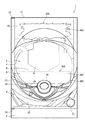
前記遊技基板5は、前面側にレール部7が設けられており、該レール部7によって遊技球で遊技を行うための遊技領域8が形成されている。該遊技領域8は、縦軸より横軸が長いほぼ横長楕円形状になっており、そうすることで従来のほぼ円形の遊技領域に比べて上下方向の寸法を短くし、その分、演出用の領域が上方に広く確保できるようにしてある。
また、遊技領域8には、上半部のほぼ中央に前後方向に貫通する演出窓9が開設されており、さらにその演出窓9の上辺とレール部7との間に遊技領域8の右側に遊技球を導くための球誘導路10が形成されている。
なお、遊技領域8には、図示しないが、遊技球の落下方向に不規則な変化を与える障害釘と、同じく風車と、遊技球を受け入れる入賞口を具備する入賞装置と、入賞装置に入賞しなかった遊技球を回収するアウト球口等が設けられている。
[Game board-Game board]
The
In addition, in the
Although not shown in the figure, the
[遊技盤−盤支持枠]
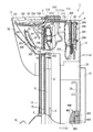
前記盤支持枠6は、前記のように遊技基板5の後面側に取り付けられており、左右の側枠板11,11と、遊技基板5と平行な背面板12とからなる。左右の側枠板11,11は、さらに上側枠板11aと下側枠板11bの二部材に分かれており、上側枠板11aには遊技基板5の上を越えてさらに前方に大きく張り出す前方延出部11cが突設されている。この盤支持枠6の左右の前方延出部11c,11c間であって遊技領域8の外側上方に形成される上部空間S1と、左右の側枠板11,11と背面板12で区画される遊技基板5後方の縦空間S2とが、後述する第1〜第4の可動装飾体100,200,300,400の移動領域となる。
また、盤支持枠6の背面板12は、その後面側であって前記遊技基板5に対向する位置に液晶等の画像表示装置13が取り付けられている。この背面板12は、透明な合成樹脂製であり、したがって画像表示装置13で表示される画像は、遊技基板5の正面から見ることができる。
[Game board-board support frame]
The
In addition, an
[遊技盤−可動装飾体]
遊技盤3には、前記のように盤支持枠6に第1の可動装飾体100と、第2の可動装飾体200と、第3の可動装飾体300と、第4の可動装飾体400が設けられているが、その詳細については前面部4の説明の後に詳述する。
[Game board-movable decorative body]
The
[前面部]
前面部4は、枠体2の前面にほぼ整合する形状であって、枠体2に設けられているヒンジ金具14,14で扉状に開閉可能なように取り付けられており、前記遊技盤3の前面を覆う閉状態と、遊技盤3の前面を露出させる開状態とに変化し得る。
前面部4は、遊技盤3の遊技領域8に対応する位置に窓部15を有する。該窓部15は、ガラスや合成樹脂等の透明板16で覆われており、したがって窓部15を介して遊技盤3の遊技領域8と、それより後方の画像表示装置13に映る画像が見える。
また、前面部4には、前記窓部15と自己の周縁部、具体的には自己の上縁部との間に遊技者側の前方に向けて膨出し且つ上面に開口部17を有する透明(無色透明に限らず、透過性を有していれば着色が施されていてもよい。)な膨出部18(カバー部)が設けられている。該膨出部18の内部には、遊技者側に向けて張り出している盤支持枠6の前方延出部11cや、第1の可動装飾体100等が収まる空間が形成されている。
その他、前面部4には、図1,図2に示したように、窓部15の下側に遊技者が操作するための入力操作部19が設けられ、また、その入力操作部19の下には遊技球を蓄える球皿20と、遊技領域8に発射される遊技球の打力を調整するための操作ハンドル21が設けられている。
[Front part]
The
The
Further, the
In addition, as shown in FIGS. 1 and 2, the
[第1の可動装飾体]
前記第1の可動装飾体100は、図1、図13、図14に示したように、想像上の動物である「龍」の顔の上半部を、頭部101と、額部102と、眼部103に分けた三つの部品で構成されるものであって、盤支持枠6の前方延出部11cに支持される。
各部品のうち、頭部101と額部102は、図13、図14に示したように額部102に固着された軸支持部104の内向き固定ピン105を、頭部101の長孔型軸受106に挿通して連結されており、固定ピン105が長孔型軸受106内を自由移動する分を遊びとして回動自在に軸着されている。
[First movable decorative body]
As shown in FIGS. 1, 13, and 14, the first movable
Of each component, the
一方、額部102と眼部103は、図14に示したように、眼部103の眉間相当部分に縦向きのスライドレール107を固着すると共に該スライドレール107を額部102の裏面中央に固着した縦向きのスライドレール108(図4、図6、図8、図12参照)に装着して連結されている。したがって、額部102に対して眼部103は、上下摺動自在になっている。
On the other hand, as shown in FIG. 14, the
また、頭部101は、前記長孔型軸受106近傍に横向きに突設した頭部摺動軸109を、盤支持枠6の前方延出部11cに設けた前後方向に長いほぼ水平な頭部摺動溝22に嵌めて摺動自在に支持される。
また、額部102は、自己の前記軸支持部104に前記内向き固定ピン105と同軸で反対向きに突設した外向の額部摺動軸110を、盤支持枠6の前方延出部11cであって前記頭部摺動溝22の下に設けた前方から後方に向かって僅かに下傾する額部摺動溝23に嵌めて摺動自在に支持される。
さらに、眼部103は、後面側を水平横断して両側方に突出する眼部摺動軸111を、盤支持枠6の前方延出部11cに設けた略への字状の眼部摺動溝24に嵌めて摺動自在に支持される。
The
Further, the
Further, the
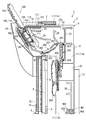
以上のように頭部101と額部102と眼部103は、互いに回動自在又は摺動自在に連結され、また、それぞれが頭部摺動溝22と額部摺動溝23と眼部摺動溝24に摺動自在に支持されており、全体として各摺動溝22,23,24を固定節とする一つの連鎖機構を構成して、それぞれの摺動軸109,110,111がそれぞれの摺動溝22,23,24の後方側の始端に位置している状態で図3、図4に示したように頭部101がうつぶせの水平姿勢に倒伏すると共に額部102と眼部103が垂直に起立して前後方向に重なった形態(第1形態)になる。かかる第1形態の第1の可動装飾体100は、前面部4の膨出部18の中に収まって外側に突出しない。
一方、それぞれの摺動軸109,110,111がそれぞれの摺動溝22,23,24の他端(眼部摺動溝24については一旦上昇して下った下端)に位置している状態では、連鎖機構のリンク関係により、図11、図12に示したように頭部101と額部102と眼部103が前傾する斜めに連なった形態(第2形態)になる。かかる第2形態に変化した第1の可動装飾体100は、龍の顔の上半分を構成し、頭部101が膨出部18の前記開口部17から外側に突出するようになっている。
このように第1の可動装飾体100は、前面部4の膨出部18内に収容された状態(第1形態)と、膨出部18の開口部17から前面部4の外側に突出した状態(第2形態)とに変化し得る。
As described above, the
On the other hand, in the state where the
Thus, the 1st
なお、額部摺動軸110と眼部摺動軸111は、図示を省略したが、例えば盤支持枠6の前方延出部11cの外側に前記制御装置で駆動制御される複数のスネークチェーン駆動装置を設けてそのスネークチェーンの先に連結されており、該スネークチェーンで各軸110,111を額部摺動溝23と眼部摺動溝24の各始端側から押し出して前方に向けて移動させ、逆にスネークチェーンを引き込んで各軸110,111を後方に向けて移動させる。もちろん眼部摺動溝24には「へ」の字の屈曲部に前記制御装置で駆動制御される電動ポイントを設けて眼部摺動軸111の進路が適宜切り替え得るようになっている。また、頭部101は、額部102の固定ピン105と長孔型軸受106で連結されているため、額部102の前記動作に従動して起立又は倒伏する。
Although the
また、実施形態では、第1の可動装飾体100の頭部101の後方に摺動蓋112が連結されている。この摺動蓋112は、前方延出部11cの上部に設けた蓋摺動溝22aに自己の両側に突設された蓋摺動軸113を挿通して水平方向に摺動自在に支持されると共に、頭部101の頭部摺動軸109と自己の蓋摺動軸113を連接棒114で繋いで頭部101の動きに従動するようになっている。
そして、第1の可動装飾体100が第1形態になって頭部101が倒伏している状態で、該頭部101が膨出部18の開口部17を塞ぐと共に、第1の可動装飾体100が第2形態になって頭部101が斜めに起立している状態で、前記摺動蓋112が開口部17の頭部101より後方の部分を塞ぐ。
さらに、第1の可動装飾体100が第2形態になって頭部101が斜めに起立している状態では、前記摺動蓋112が開口部17を塞ぐのに加え、後述する第3の可動装飾体300の表示プレート301が、膨出部18の内部における遊技領域8への侵入経路を阻害する位置に設けられるようになっている。すなわち、第1の可動装飾体100が第2形態になって頭部101が斜めに起立している状態では、前記摺動蓋112と、第3の可動装飾体300の表示プレート301とによって、二重で遊技領域8への異物侵入を防止する構造となっている。
このように実施形態では、第1の可動装飾体100の頭部101と摺動蓋112が各形態(第1形態、第2形態)にて膨出部18の開口部17を塞ぎ、膨出部18の開口を介して遊技領域8に異物が侵入することを困難にしている。また、第3の可動装飾体300の表示プレート301によって、第2形態時の遊技領域8への異物侵入をより困難にしている。よって、第1の可動装飾体100の頭部101、摺動蓋112、および、第3の可動装飾体300の表示プレート301は、膨出部18の開口を介して遊技領域8に異物が侵入することを防止する(抑制する)不正防止手段になっている。
In the embodiment, the sliding
Then, in a state where the first movable
Further, in a state where the first movable
Thus, in the embodiment, the
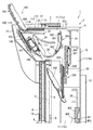
[第2の可動装飾体200]
第2の可動装飾体200は、前記龍の顔の下半部である鼻と口を構成するものであり、前記第1の可動装飾体100とは機構上の繋がりのない別部品であって、前記遊技基板5のほぼ上半部をカバーし得る大きさのバックパネル201と、該バックパネル201の前面ほぼ中央に上下摺動可能に設けられた昇降軸支部202と、該昇降軸支部202の前面下部に自己の下部を回動可能に軸着してほぼ垂直な起立姿勢と傾斜した前傾姿勢とに変化し得るように支持された鼻口部203と、からなる。
なお、図示を省略したが、第2の可動装飾体200には、バックパネル201に対して昇降軸支部202を昇降させる例えば前記制御装置で駆動制御されるスクリュー式の昇降手段が設けられている。さらに、第2の可動装飾体200には、図示を省略したが前記鼻口部203を前記制御装置で駆動制御して前傾・起立させるモーターやソレノイド等の回動駆動手段が設けられており、昇降軸支部202が上昇位置にあるとき鼻口部203を起立姿勢に回動保持し、一方、昇降軸支部202が下降位置にあるとき鼻口部203を前傾姿勢に回動して保持するようになっている。
[Second movable decorative body 200]
The second movable
Although not shown, the second movable
第2の可動装飾体200は、前記バックパネル201の両側面に上下二本の鼻口摺動軸204を有しており、該鼻口摺動軸204を盤支持枠6の上側枠板11a,11aに設けた鼻口摺動溝25に挿通して前後方向と上下方向に摺動自在に支持されている。
鼻口摺動軸204は、図示を省略したが、例えば上側枠板11aの外側に、水平方向に移動させる例えば前記制御装置で駆動制御されるスクリュー式の水平移動手段と、該水平移動手段を鼻口摺動軸204ごと垂直方向に移動させる例えば前記制御装置で駆動制御されるスクリュー式の垂直移動手段を設けて、鼻口摺動溝25に沿って前後方向と上下方向に自由に移動させ得るようになっている。
The second movable
Although the illustration of the
第2の可動装飾体200は、図3、図4に示したように垂直に起立させた鼻口部203の後に昇降軸支部202とバックパネル201を並べた状態で最も上昇させた位置にあり、一方、図5、図6に示したようにバックパネル201を上側枠板11aに対して下降させ、そのバックパネル201から図7、図8に示したように昇降軸支部202を下降させ、その昇降軸支部202から図9、図10に示したように鼻口部203を前傾させると、鼻口部203の上端が遊技基板5の演出窓9の内部に臨んで第1の可動装飾体100の頭部101と額部102と眼部103に連なる。これにより図1に示したように遊技者を見下ろす巨大な龍の顔が完成する。
The second movable
[第3の可動装飾体]
第3の可動装飾体300は、盤支持枠6の前方延出部11c,11cに支持されており、該前方延出部11c,11cの高さより若干小さく且つ前方延出部11c,11cの左右の間隔より若干小さな幅の表示プレート301と、該表示プレート301の上下両側に突設されたプレート摺動軸302で形成されている。この表示プレート301の前面には、機種名を表す文字やキャラクターなどの図形が描かれており、第1の可動装飾体100が第1形態にあるときには、透明な膨出部18の前方から表示プレート301が視認可能となるように設けられている。
第3の可動装飾体300は、両側のプレート摺動軸302を盤支持枠6の前方延出部11cに形成したプレート摺動溝26に挿通して支持されている。該プレート摺動溝26は、第1の可動装飾体100との干渉を避けるため遊技基板5に近い低所を通るようになっており、したがって表示プレート301は、プレート摺動溝26に沿って前方延出部11cの前方から遊技基板5に近い低所を通って後方に移動し得る。
[Third movable decoration]
The third movable
The third movable
なお、表示プレート301をプレート摺動溝26に沿って移動させる駆動手段はどのようなものでもよいが、実施形態では、図17に示したようにプレート摺動溝26の内壁上面側にラックギヤ27を形成し、一方、プレート摺動軸302に円形ギヤ303を固着して該円形ギヤ303を前記ラックギヤ27に噛合させ、さらにプレート摺動軸302に回転自由な転動輪304を設けてプレート摺動溝26の内壁下面に当接させるようになし、そうして円形ギヤ303を前記制御装置で駆動制御されるモーターで任意の方向に回転させるようにしている。
The driving means for moving the
また、前述したように、第1の可動装飾体100が第2形態になって頭部101が斜めに起立している状態では、前記摺動蓋112が開口部17を塞ぐのに加え、第3の可動装飾体300の表示プレート301が、膨出部18の内部における遊技領域8への侵入経路を阻害する位置に設けられると共に異物の侵入方向に対して凹状の湾曲面を対向させて異物の方向制御が困難になるようになっており、第3の可動装飾体300の表示プレート301によって、第2形態時の遊技領域8への異物侵入をより困難にしている。
Further, as described above, in the state where the first movable
[第4の可動装飾体]
第4の可動装飾体400は、盤支持枠6の下側枠板11b,11bに前後移動及び昇降可能に支持されており、横長平板形状の棒主部401と、その棒主部401の前面の上下コーナー位置に回転中心が設定された開閉可能な表示ウイング402,402と、棒主部401の上下両側に突設された棒摺動軸403で形成されている。
この第4の可動装飾体400は、棒主部401の前面を表示ウイング402,402が覆う図3、図4の閉じ状態で麻雀ゲームのリーチ棒を連想させる形態を呈し、また、表示ウイング402,402が全開して該表示ウイング402,402の内面と棒主部401の前面が面一になった図9、図10の展開状態になったとき、その展開面を使って遊技内容に関連する文字や図形が大きく表示されるようになっている。
第4の可動装飾体400は、両側の棒摺動軸403を盤支持枠6の下側枠板11bに形成したほぼF字形の棒摺動溝28に挿通して支持されており、該棒摺動溝28に沿って前記遊技基板5の遊技領域8の下側後方に対応する図3、図4の低位置から、同じく遊技領域8の前記演出窓9の後方に対応する図11、図12の高位置の間で昇降し、且つ、その高位置で前後方向に移動し得る。
なお、棒主部401を棒摺動溝28に沿って移動させる駆動手段は、前記した第2の可動装飾体200と同じである。
[The fourth movable decoration]
The fourth movable
The fourth movable
The fourth movable
The driving means for moving the rod
その他、図示しないが、前記盤支持枠6のさらに後側に、球タンク、球導出樋、景品球払出装置、景品球放出樋などをユニット化した機構盤が装着されている。
In addition, although not shown, on the further rear side of the
上記遊技機1の通常の遊技状態(通常状態)は、図2、図3、図4に示したように、第1の可動装飾体100が、前面部4の膨出部18からはみ出さない前記第1形態になっており、また、第2の可動装飾体200が、盤支持枠6の最上昇位置にあり、また、第3の可動装飾体300の表示プレート301が膨出部18の前面に臨んでいる。一方、第4の可動装飾体400は、表示ウイング402,402を閉じて遊技基板5の遊技領域8の下側後方に対応する低位置に停止している。
この通常状態は、遊技領域8に打ち込まれる遊技球が遊技領域8に設けられる所定の入賞口(たとえば始動口)に入賞すると、該入賞に起因して大当りとするか否かの大当り抽選が行われる状態であり、該大当り抽選の結果を示唆する演出として、例えば画像表示装置13の画像や、第4の可動装飾体300の昇降等による演出が行われて遊技が進行する。
In the normal gaming state (normal state) of the
In this normal state, when a game ball driven into the
次に、遊技球の入賞に起因して行われる大当り抽選の結果が大当り結果となった場合に発生する大当り状態(遊技者に所定量の遊技球を付与する状態)になった場合の各種の可動装飾体100,200,300,400の動作について説明する。
大当り状態になった場合には、前記制御装置で各駆動手段が駆動制御されて、例えば、先ず図5、図6のように最も上昇した位置にある第2の可動装飾体200のバックパネル201を下降させ、次に図7、図8のようにバックパネル201から昇降軸支部202を下降させ、続いて図9、図10のように昇降軸支部202から鼻口部203を前傾させて停止させる。
Next, various types of jackpots (when the player is given a predetermined amount of gaming balls) which occurs when the result of the jackpot lottery performed due to the winning of the gaming balls is a big hit result The operation of the movable
When the big hit state is reached, each drive means is driven and controlled by the control device. For example, first, the
次に、図3、図5、図7、図9のように膨出部18の前方にある第3の可動装飾体300の表示プレート301を後方に移動させ、同時に第1形態にある第1の可動装飾体100を図3、図5、図7、図9のように第2形態に変化させて頭部101と額部102と眼部103を斜めに連ならせ、そうして先に移動・停止している第2の可動装飾体200と視覚的に融合させて遊技者を見下ろす巨大な龍の顔を完成させる。このとき頭部101の上半部が膨出部18から前面部4の外方に突出してはみ出しているため、より立体的でダイナミックな演出効果が得られる。この結果、遊技者に意外性や驚きを与え、従来に比して遊技興趣を高められる。
Next, as shown in FIG. 3, FIG. 5, FIG. 7, and FIG. 9, the
なお、図11に想像線で示したように、遊技場の島設備には、遊技機1上方の幕板Xに遊技の進行状況(大当り遊技の発生回数など)を示すデータ表示体Yが設けられるのが一般であり、第2形態で上方に突出した第1の可動装飾体100の頭部101の存在によってデータ表示体Yが隠れてしまい、データ表示体Yの視認性を低下させてしまうことが考えられる。
これを防止するため実施形態では、第1の可動装飾体100を第2形態から第1形態に戻すためのスイッチ29(遊技者が操作可能な操作部)が遊技機1の前面に設けられている。そして、大当り状態になって第1の可動装飾体100が第1形態から第2形態に変わっているとき、データ表示体Yを確認したい遊技者が前記スイッチ29を入力すると、その入力検知に基づき第2形態にある第1の可動装飾体100を第1形態に戻すように第1の可動装飾体100を駆動制御する。これにより第1の可動装飾体100の頭部101が膨出部18内に下がって、隠れていたデータ表示体Yの確認が可能となる。
さらに、スイッチ29の入力検知に基づき第1の可動装飾体100を第1形態に戻した後、再度スイッチ29を入力すると、第1形態にある第1の可動装飾体100を第2形態に戻すように駆動制御する。これにより、第1の可動装飾体100を第1形態に戻した後にデータ表示体Yを確認した遊技者が、任意で第1の可動装飾体100を第2形態に戻すことができる。
なお、「再度のスイッチ29の入力検知に基づき第1の可動装飾体100を第2形態に戻すように駆動制御することが可能な時期」は、あらかじめ定めておくことが望ましく、本実施形態では、この時期を、第1の可動装飾体100が第2形態に変化する「大当り状態の継続中」に設定している。また、この場合、大当り状態が継続している間であれば、スイッチ29の入力回数に制限を設けず、何度でも第1の可動装飾体100の形態を変更可能としている。
なお、別形態として、図19に示したように、第1の可動装飾体100を第2形態から第1形態に戻すためのスイッチ29Xと、該スイッチ29Xの入力によって第1形態に戻された第2の可動装飾体200を再び第2形態に戻すためのスイッチ29Yを別体で設ける構成としてもよい。
また、スイッチ29の入力検知に基づき第1の可動装飾体100を第1形態に戻した後、所定時間(例えば5秒)の経過に基づき、第1形態にある第1の可動装飾体100を第2形態に戻すように駆動制御するように設定してもよい。なお、こうした形態では、所定時間が経過するまでの間に、前述の「第1の可動装飾体100を第2形態に戻すように駆動制御することが可能な時期(本実施形態では「大当り状態」)」が終了する場合には、所定時間が経過しても第1の可動装飾体100を第1形態のまま維持することが考えられる。
また、スイッチ29の入力検知に基づき第1の可動装飾体100を駆動させる際には、スイッチ29の入力検知に基づいて、音声、ランプ、あるいは、表示装置を用いて「第1の可動装飾体100の駆動を知らせる報知」を行うようにしてもよい(報知手段)。そうした報知(注意喚起)により、意図しない第1の可動装飾体100の駆動により遊技者に怪我をさせる等を防止でき、安全性を高められる。
さらには、音声、ランプ、あるいは、表示装置を用いて、「スイッチ29の入力検知に基づき第1の可動装飾体100を駆動させることができる旨の説明」を行うようにしてもよい(説明手段)。そうした報知(事前説明)により、任意に第1の可動装飾体100を駆動させることができることを遊技者に認識させることができ、利便性を高められる。
斯かるスイッチ29に関する構成については、遊技盤3に可動装飾体100,200,300,400を一体に設けるようにした実施形態の遊技機1のほか、遊技盤3と可動装飾体100,200,300,400とを別体に設けるようにした遊技機にも適用可能であり、さらには、枠体外方に突出駆動する可動装飾体を枠体(外枠、本体枠など)の所定部位に設けるようにした遊技機や、筐体外方に突出駆動する可動装飾体を筐体の所定部位に設けるようにした回胴式遊技機(スロットマシン)にも適用可能である。
As indicated by the imaginary line in FIG. 11, the island facility of the game hall is provided with a data display body Y indicating the progress of the game (the number of occurrences of the big hit game, etc.) on the curtain board X above the
In order to prevent this, in the embodiment, a switch 29 (an operation unit operable by the player) for returning the first movable
Further, after the first movable
It should be noted that it is desirable to predetermine “a time when the first movable
As another form, as shown in FIG. 19, the
Moreover, after returning the 1st
Further, when the first movable
Furthermore, “explaining that the first movable
Regarding the configuration relating to such a
次に、図9〜図11のように低位置にある第4の可動装飾体400の表示ウイング402,402を上下に展開させて高位置に移動させると、それが第2の可動装飾体200の鼻口部203の後方に位置するため、遊技者の目線では龍が展開したリーチ棒をくわえているように見える。この結果、より立体的でダイナミックな演出効果が得られ、遊技者に意外性や驚きを与え、従来に比して遊技興趣を高められる。
Next, as shown in FIGS. 9 to 11, when the
そして、大当り状態が終了すると、上記と逆の工程を辿って第1〜第4の可動装飾体100〜400が通常の遊技状態に復動する。
When the big hit state is completed, the first to fourth movable
しかして、実施形態の遊技機1は、図15(a),(b)のように遊技盤3を外して別の遊技盤に交換すると、前面部4の膨出部18の装飾も新しい遊技盤に付属する可動装飾体に変わるため、前面部4と遊技盤3のデザインがちぐはぐになるようなおそれがない。
Thus, when the
以上、本発明を実施の形態について説明したが、もちろん本発明は上記実施形態に限定されるものではない。例えば、実施形態では、盤支持枠6によって遊技基板5の上部と後方に上部空間S1と縦空間S2を設けて可動装飾体100〜400を広い範囲で移動・変化させるようにしたが、遊技基板5の上部に上部空間S1のみを設けてその範囲で可動装飾体を移動・変化させるようにしてもよい。具体的には、可動装飾体を実施形態の第1の可動装飾体100のみにしてもよい。なお、その場合には、第2の可動装飾体200に相当する鼻口部分、つまり可動装飾体に関連する又は補完する画像を画像表示装置13で表示するようにするとよい。
The embodiment of the present invention has been described above, but of course the present invention is not limited to the above embodiment. For example, in the embodiment, the upper space S1 and the vertical space S2 are provided by the
また、実施形態では、通常状態において膨出部18の前面に第3の可動装飾体300の表示プレート301を認識可能となるように臨ませるようにしたが、通常状態において膨出部18内で動的に変化する可動装飾体を設けるようにしてもよい。
また、実施形態では、大当り状態において第1の可動装飾体100を第1形態から第2形態に変化させるように駆動制御するようにしたが、通常状態にて所定の駆動条件が成立した場合や、遊技が行われていない非遊技状態(デモ状態など)に第1の可動装飾体100を第1形態から第2形態に変化させるように駆動制御するようにしてもよい。
また、実施形態では、一般的な遊技機に存在する枠体と前面部の間の本体部を設けていないが、もちろん従来と同様な本体部を設けてその本体部に遊技盤を着脱自在に装着するようにしてもよい。
また、実施形態では遊技基板5を透明な合成樹脂製としたが、不透明な素材で形成してもよい。
また、実施形態では膨出部18透過性を有する部材としたが、不透明な部材で形成してもよい。こうすることで、通常状態(第1形態)では外部から視認不能とされる可動装飾体が、第2形態に変わって突然に視認可能になることで、遊技者に一層の意外性や驚きを与えて遊技興趣を向上させることができる。
また、実施形態では、膨出部18を前面部4の上部に設けて開口部17を上に設けたが、膨出部18を前面部4の側部に設けて開口部17を横方向に設けるか、あるいは上部と側部の双方、つまり、例えば前面部4の正面向かって右上角部に開口部17を設けるようにしてもよい。
In the embodiment, the
In the embodiment, the first movable
Also, in the embodiment, the main body between the frame and the front face present in a general game machine is not provided, but of course a main body similar to the conventional one is provided and the game board can be detachably attached to the main body. You may attach it.
In the embodiment, the
Moreover, although it was set as the member which has the bulging
Further, in the embodiment, the bulging
また、実施形態では、盤支持枠6の背面板12の後面側に画像表示装置13を取り付けるようにしたが、背面板12の前面側に画像表示装置13を取り付けるようにしてもよい。このとき、第4の可動装飾体400を設けるスペースがない場合は設けなくてもよい。また、図18に示したように、第4の可動装飾体400を有する下側枠板11bを、画像表示装置13を設けた機構盤Zに置き換えるようにしてもよい。
In the embodiment, the
また、第1の可動装飾体100、第2の可動装飾体200、第3の可動装飾体300の夫々が何れの形態にあるかを検知可能な検知センサ(駆動状態検知手段)を設け、第1の可動装飾体100、第2の可動装飾体200、第3の可動装飾体300の形態を変化させるように駆動制御したにもかかわらず、当該検知センサによって対応する形態が検知されない場合に異常と判断し、音声、ランプ、あるいは、表示装置を用いて、外部に向けてエラー報知を行う構成を付加するようにしてもよい。これにより、可動装飾体に異常が生じた際に迅速な発見・対応が可能となり、当該遊技機の信頼性を高められる。
Further, a detection sensor (drive condition detection means) capable of detecting which of the first movable
さらに、第1の可動装飾体100が第1形態にあるときに、第1の可動装飾体100の上部に何らかの物体が置かれている場合に、その旨を検知することができる検知センサ(物体検知手段)を設け、当該検知センサによって第1の可動装飾体100の上部に何らかの物体が置かれていることが検知された場合に異常と判断し、音声、ランプ、あるいは、表示装置を用いて、外部に向けてエラー報知あるいは注意喚起の報知(「物を載せないでください」の報知など)を行う構成を付加するようにしてもよい。さらには、当該検知センサによって第1の可動装飾体100の上部に何らかの物体が置かれていることが検知された場合には、第1の可動装飾体100が第1形態から第2形態になる条件が成立しても、第1の可動装飾体100を第2形態に変化させずに第1形態のまま維持するように構成してもよい。これらの構成により、第1の可動装飾体100の上部に置かれた物体の落下等で遊技者が怪我をする等の被害が生ずることを未然に防止でき、当該遊技機の信頼性を高められる。なお、検知センサ(物体検知手段)としては、重量を検知する重量検知センサや、第1の可動装飾体100上面への接触を検知する接触検知センサ等が挙げられる。
Furthermore, when the first movable
ところで、上記した本発明の可動装飾体や盤支持枠の構成は、遊技基板と切り離して枠体に装着した場合(つまり、遊技基板のみを交換対象とする場合)でも、ダイナミックな演出効果が得られる点において十分な技術的価値がある。 By the way, the above-described configuration of the movable decorative body and the board support frame of the present invention provides a dynamic effect even when the game board is separated from the game board and attached to the frame body (that is, when only the game board is to be replaced). There is sufficient technical value in terms of
1 …遊技機
2 …枠体
3 …遊技盤
4 …前面部
8 …遊技領域
15 …窓部
18 …膨出部
100 …第1の可動装飾体
DESCRIPTION OF
Claims (3)
前記図柄の変動表示が行われる図柄表示部と、
前記図柄表示部の上側で前方に突出して設けられた可動装飾演出部と、を備え、
前記可動装飾演出部は、
当該遊技機の外形の一部を構成し、特定装飾を有する装飾面部が下側に向いた通常状態と、該通常状態に比べて前記特定装飾を有する装飾面部が正面側に向いた上昇状態とに変化可能であり、前記通常状態から前記上昇状態に変化することで当該遊技機の外形に変化を与えるものであって、
前記通常状態では、前記特定装飾を有する装飾面部が下側を向きつつも前記特定装飾の少なくとも一部が遊技者から視認可能とされ、前記上昇状態では、前記特定装飾を有する装飾面部が正面側を向いて前記通常状態とは異なる態様で前記特定装飾が視認可能とされるものであり、
さらに、前記通常状態では、前記特定装飾を有する装飾面部とは別の装飾面部が正面側を向いて位置しており、該別の装飾面部は、前記可動装飾演出部が前記通常状態から前記上昇状態に変化することに伴って他の位置に移動するものであり、
さらに、前記図柄表示部を有する遊技盤と、
当該遊技機の前面側を構成し、前記遊技盤を視認可能にする窓部を有する前扉部と、を備え、
前記可動装飾演出部は、前記前扉部に設けられるものであり、
前記遊技盤に設けられ、前記可動装飾演出部とは異なる盤側装飾演出部をさらに備え、
前記可動装飾演出部が前記上昇状態になることに並行して前記盤側装飾演出部が動作可能に設けられ、前記可動装飾演出部および前記盤側装飾演出部が並行して動作する過程で一体的な装飾を創出可能である
ことを特徴とする遊技機。 In a gaming machine that performs variable display of symbols based on the establishment of start conditions, and provides gaming benefits based on the results of the variable display,
A symbol display unit on which the variable display of the symbol is performed;
A movable decorative effect part provided to project forward on the upper side of the symbol display part;
The movable decoration effect unit is
A normal state in which a decorative surface part having a specific decoration faces downward, constituting a part of the outer shape of the gaming machine, and a raised state in which the decorative surface part having the specific decoration faces the front side as compared to the normal state. Change to the outer shape of the gaming machine by changing from the normal state to the raised state,
In the normal state, at least a part of the specific decoration is visible from the player while the decorative surface having the specific decoration faces downward, and in the raised state, the decorative surface having the specific decoration is on the front side And the specific decoration is visible in a mode different from the normal state.
Furthermore, in the normal state, a decorative surface portion different from the decorative surface portion having the specific decoration faces the front side, and in the other decorative surface portion, the movable decorative effect portion rises from the normal state Move to another position as the state changes,
Furthermore, a game board having the symbol display unit,
A front door portion having a window portion that constitutes a front side of the gaming machine and makes the gaming board visible; and
The movable decoration effect part is provided in the front door part,
The game board further includes a board-side decoration effect part provided on the game board and different from the movable decoration effect part,
The board side decoration effect part is provided so as to be operable in parallel with the movable decoration effect part being in the raised state, and the movable decoration effect part and the board side decoration effect part are integrally operated in parallel. A game machine characterized by the ability to create unique decorations.
前記可動装飾演出部が前記通常状態にあるときには、前記透過部を介して前記特定装飾を遊技者に視認可能にし、
前記可動装飾演出部が前記上昇状態にあるときには、前記透過部を介することなく、該透過部の上方で前記特定装飾を遊技者に直視可能にする
ことを特徴とする請求項1に記載の遊技機。 A transmission part provided on the front door part and having transparency;
When the movable decoration effect part is in the normal state, the specific decoration is made visible to the player through the transparent part,
The gaming machine according to claim 1, wherein the specific decoration can be directly viewed by the player above the transparent portion without the transparent portion when the movable decorative effect portion is in the raised state. Machine.
前記図柄の変動表示が行われる図柄表示部を有する遊技盤と、
当該遊技機の前面側を構成し、前記遊技盤を視認可能にする窓部を有する前扉部と、
前記前扉部に形成された膨出部に設けられ、通常状態と、該通常状態よりも上昇した上昇状態とに変化可能な可動装飾演出部と、
前記前扉部に形成された膨出部に設けられ、透過性を有する透過部と、
を備え、
前記可動装飾演出部は、当該遊技機の外形の一部を構成する部材であり、前記通常状態から前記上昇状態に変化することで、当該遊技機の外形が変化するものであり、
前記膨出部は、前記可動装飾演出部の動作に要する開口を上面に有しており、
前記透過部は、前記開口よりも下方に設けられており、
前記可動装飾演出部が前記通常状態にあるときには、前記可動装飾演出部そのものが前記開口を塞ぐように配置されると共に、前記開口よりも下方に設けられる前記透過部を介して前記可動装飾演出部による装飾を遊技者に視認可能にし、
前記可動装飾演出部が前記上昇状態にあるときには、前記透過部を介することなく、前記膨出部の上方で前記可動装飾演出部による装飾を遊技者に直視可能にする
ことを特徴とする遊技機。 In a gaming machine that performs variable display of symbols based on the establishment of start conditions, and provides gaming benefits based on the results of the variable display,
A game board having a symbol display portion on which the symbol variation display is performed;
A front door portion having a window portion that constitutes a front side of the gaming machine and makes the gaming board visible;
A movable decoration effect part provided in the bulging part formed on the front door part and capable of changing between a normal state and a rising state which is higher than the normal state;
A permeable portion provided on the bulging portion formed on the front door portion and having permeability;
Equipped with
The movable decoration effect part is a member constituting a part of the outer shape of the gaming machine, and the outer shape of the gaming machine changes by changing from the normal state to the raised state.
The bulging part has an opening required for the operation of the movable decorative effect part on the upper surface,
The transmission part is provided below the opening,
When the movable decoration effect part is in the normal state, the movable decoration effect part itself is disposed so as to close the opening, and the movable decoration effect part is provided via the transmission part provided below the opening. Make the decoration by the player visible to the player,
When the movable decoration effect part is in the raised state, a player can directly view the decoration by the movable decoration effect part above the bulging part without interposing the transmission part. .
Priority Applications (1)
| Application Number | Priority Date | Filing Date | Title |
|---|---|---|---|
| JP2016223814A JP6553016B2 (en) | 2016-11-17 | 2016-11-17 | Game machine |
Applications Claiming Priority (1)
| Application Number | Priority Date | Filing Date | Title |
|---|---|---|---|
| JP2016223814A JP6553016B2 (en) | 2016-11-17 | 2016-11-17 | Game machine |
Related Parent Applications (1)
| Application Number | Title | Priority Date | Filing Date |
|---|---|---|---|
| JP2016020709A Division JP6086337B2 (en) | 2016-02-05 | 2016-02-05 | Game machine |
Related Child Applications (1)
| Application Number | Title | Priority Date | Filing Date |
|---|---|---|---|
| JP2018118251A Division JP2018140278A (en) | 2018-06-21 | 2018-06-21 | Game machine |
Publications (3)
| Publication Number | Publication Date |
|---|---|
| JP2017029843A JP2017029843A (en) | 2017-02-09 |
| JP2017029843A5 JP2017029843A5 (en) | 2017-09-14 |
| JP6553016B2 true JP6553016B2 (en) | 2019-07-31 |
Family
ID=57987401
Family Applications (1)
| Application Number | Title | Priority Date | Filing Date |
|---|---|---|---|
| JP2016223814A Active JP6553016B2 (en) | 2016-11-17 | 2016-11-17 | Game machine |
Country Status (1)
| Country | Link |
|---|---|
| JP (1) | JP6553016B2 (en) |
Family Cites Families (7)
| Publication number | Priority date | Publication date | Assignee | Title |
|---|---|---|---|---|
| JP2004016722A (en) * | 2002-06-20 | 2004-01-22 | Takao:Kk | Game machine |
| JP2009034251A (en) * | 2007-07-31 | 2009-02-19 | Aruze Corp | Game machine |
| JP2011098040A (en) * | 2009-11-05 | 2011-05-19 | Kyoraku Sangyo Kk | Game machine |
| JP5168293B2 (en) * | 2010-01-22 | 2013-03-21 | 奥村遊機株式会社 | Game machine |
| JP2012152621A (en) * | 2012-05-23 | 2012-08-16 | Taiyo Elec Co Ltd | Game machine |
| JP2013138892A (en) * | 2013-03-13 | 2013-07-18 | Daito Giken:Kk | Game machine |
| JP5763725B2 (en) * | 2013-08-27 | 2015-08-12 | 株式会社ユニバーサルエンターテインメント | Game machine |
-
2016
- 2016-11-17 JP JP2016223814A patent/JP6553016B2/en active Active
Also Published As
| Publication number | Publication date |
|---|---|
| JP2017029843A (en) | 2017-02-09 |
Similar Documents
| Publication | Publication Date | Title |
|---|---|---|
| JP6060944B2 (en) | Game machine | |
| JP6138091B2 (en) | Game machine | |
| JP4888939B2 (en) | Bullet ball machine | |
| JP4588050B2 (en) | Decorative body elevating unit, game board, and pachinko machine | |
| JP5927474B2 (en) | Game machine | |
| JP4834648B2 (en) | Game machine | |
| JP5138755B2 (en) | Bullet ball machine | |
| JP4654254B2 (en) | Decorative body unit, game board, and pachinko machine | |
| JP4809861B2 (en) | Bullet ball machine | |
| JP5148833B2 (en) | Game machine | |
| JP6485869B2 (en) | Game machine | |
| JP2007029420A (en) | Game machine | |
| JP6395231B2 (en) | Game machine | |
| JP6553016B2 (en) | Game machine | |
| JP6516351B2 (en) | Gaming machine | |
| JP6086337B2 (en) | Game machine | |
| JP2009066353A (en) | Pinball game machine | |
| JP6347526B2 (en) | Game machine | |
| JP4729554B2 (en) | Game machine | |
| JP6320492B2 (en) | Game machine | |
| JP2018140278A (en) | Game machine | |
| JP2018140277A (en) | Game machine | |
| JP4753925B2 (en) | Game machine | |
| JP2009066352A (en) | Pinball game machine | |
| JP6139485B2 (en) | Game machine |
Legal Events
| Date | Code | Title | Description |
|---|---|---|---|
| A621 | Written request for application examination |
Free format text: JAPANESE INTERMEDIATE CODE: A621 Effective date: 20161122 |
|
| A521 | Request for written amendment filed |
Free format text: JAPANESE INTERMEDIATE CODE: A523 Effective date: 20170802 |
|
| A131 | Notification of reasons for refusal |
Free format text: JAPANESE INTERMEDIATE CODE: A131 Effective date: 20171005 |
|
| A601 | Written request for extension of time |
Free format text: JAPANESE INTERMEDIATE CODE: A601 Effective date: 20171201 |
|
| A521 | Request for written amendment filed |
Free format text: JAPANESE INTERMEDIATE CODE: A523 Effective date: 20180125 |
|
| A02 | Decision of refusal |
Free format text: JAPANESE INTERMEDIATE CODE: A02 Effective date: 20180510 |
|
| A521 | Request for written amendment filed |
Free format text: JAPANESE INTERMEDIATE CODE: A523 Effective date: 20180621 |
|
| A911 | Transfer to examiner for re-examination before appeal (zenchi) |
Free format text: JAPANESE INTERMEDIATE CODE: A911 Effective date: 20180622 |
|
| A131 | Notification of reasons for refusal |
Free format text: JAPANESE INTERMEDIATE CODE: A131 Effective date: 20180821 |
|
| A521 | Request for written amendment filed |
Free format text: JAPANESE INTERMEDIATE CODE: A523 Effective date: 20181015 |
|
| A912 | Re-examination (zenchi) completed and case transferred to appeal board |
Free format text: JAPANESE INTERMEDIATE CODE: A912 Effective date: 20181228 |
|
| A521 | Request for written amendment filed |
Free format text: JAPANESE INTERMEDIATE CODE: A523 Effective date: 20190509 |
|
| A61 | First payment of annual fees (during grant procedure) |
Free format text: JAPANESE INTERMEDIATE CODE: A61 Effective date: 20190703 |
|
| R150 | Certificate of patent or registration of utility model |
Ref document number: 6553016 Country of ref document: JP Free format text: JAPANESE INTERMEDIATE CODE: R150 |
|
| R250 | Receipt of annual fees |
Free format text: JAPANESE INTERMEDIATE CODE: R250 |