JP6552829B2 - Directional switching valve - Google Patents

Directional switching valve Download PDF

Info

Publication number
JP6552829B2
JP6552829B2 JP2015014773A JP2015014773A JP6552829B2 JP 6552829 B2 JP6552829 B2 JP 6552829B2 JP 2015014773 A JP2015014773 A JP 2015014773A JP 2015014773 A JP2015014773 A JP 2015014773A JP 6552829 B2 JP6552829 B2 JP 6552829B2
Authority
JP
Japan
Prior art keywords
passage
pump
bridge
unload
tandem
Prior art date
Legal status (The legal status is an assumption and is not a legal conclusion. Google has not performed a legal analysis and makes no representation as to the accuracy of the status listed.)
Active
Application number
JP2015014773A
Other languages
Japanese (ja)
Other versions
JP2016138619A (en
Inventor
崎 仁 岩
崎 仁 岩
部 明 紀 阿
部 明 紀 阿
Current Assignee (The listed assignees may be inaccurate. Google has not performed a legal analysis and makes no representation or warranty as to the accuracy of the list.)
Nabtesco Corp
Original Assignee
Nabtesco Corp
Priority date (The priority date is an assumption and is not a legal conclusion. Google has not performed a legal analysis and makes no representation as to the accuracy of the date listed.)
Filing date
Publication date
Application filed by Nabtesco Corp filed Critical Nabtesco Corp
Priority to JP2015014773A priority Critical patent/JP6552829B2/en
Priority to KR1020160009352A priority patent/KR101790427B1/en
Priority to CN201610060582.1A priority patent/CN105822793B/en
Publication of JP2016138619A publication Critical patent/JP2016138619A/en
Application granted granted Critical
Publication of JP6552829B2 publication Critical patent/JP6552829B2/en
Active legal-status Critical Current
Anticipated expiration legal-status Critical

Links

Images

Classifications

    • FMECHANICAL ENGINEERING; LIGHTING; HEATING; WEAPONS; BLASTING
    • F16ENGINEERING ELEMENTS AND UNITS; GENERAL MEASURES FOR PRODUCING AND MAINTAINING EFFECTIVE FUNCTIONING OF MACHINES OR INSTALLATIONS; THERMAL INSULATION IN GENERAL
    • F16KVALVES; TAPS; COCKS; ACTUATING-FLOATS; DEVICES FOR VENTING OR AERATING
    • F16K11/00Multiple-way valves, e.g. mixing valves; Pipe fittings incorporating such valves
    • F16K11/02Multiple-way valves, e.g. mixing valves; Pipe fittings incorporating such valves with all movable sealing faces moving as one unit
    • F16K11/06Multiple-way valves, e.g. mixing valves; Pipe fittings incorporating such valves with all movable sealing faces moving as one unit comprising only sliding valves, i.e. sliding closure elements
    • F16K11/065Multiple-way valves, e.g. mixing valves; Pipe fittings incorporating such valves with all movable sealing faces moving as one unit comprising only sliding valves, i.e. sliding closure elements with linearly sliding closure members
    • F16K11/07Multiple-way valves, e.g. mixing valves; Pipe fittings incorporating such valves with all movable sealing faces moving as one unit comprising only sliding valves, i.e. sliding closure elements with linearly sliding closure members with cylindrical slides

Description

本発明は、方向切換弁に関する。   The present invention relates to a direction switching valve.

従来より、2つのポンプから1つのアクチュエータに油が供給される油圧回路がある(特許文献1および特許文献2など)。例えば、特許文献1に記載の油圧回路は、第1のポンプ(10)の吐出油をアクチュエータに供排する第1系統の方向切換弁(32、34A,34B、34C、34D)と、第2のポンプ(12)の吐出油をアクチュエータに供排する第2系統の方向切換弁(42、44A、44B、44C)と、を備える。この油圧回路では、ブーム用シリンダ(24B)に、第1のポンプ(10)および第2のポンプ(12)の吐出油が供給される。ブーム用シリンダ(24B)には、第1系統の方向切換弁(34C)と、第2系統の方向切換弁(44B)と、が接続される。また、アーム用シリンダ(24C)には、第1のポンプ(10)および第2のポンプ(12)の吐出油が供給される。アーム用シリンダ(24C)には、第1系統の方向切換弁(34D)と、第2系統の方向切換弁(44C)と、が接続される。   Conventionally, there is a hydraulic circuit in which oil is supplied from two pumps to one actuator (for example, Patent Document 1 and Patent Document 2). For example, the hydraulic circuit described in Patent Document 1 includes a first system direction switching valve (32, 34A, 34B, 34C, 34D) for discharging and discharging discharged oil of the first pump (10) to the actuator, And a directional control valve (42, 44A, 44B, 44C) of a second system for discharging the discharge oil of the pump (12) to the actuator. In this hydraulic circuit, discharge oil of the first pump (10) and the second pump (12) is supplied to the boom cylinder (24B). A first system direction switching valve (34C) and a second system direction switching valve (44B) are connected to the boom cylinder (24B). Also, the discharge oil from the first pump (10) and the second pump (12) is supplied to the arm cylinder (24C). A first direction switching valve (34D) and a second direction switching valve (44C) are connected to the arm cylinder (24C).

特開平10−18360号公報Japanese Patent Laid-Open No. 10-18360 特開2013−238291号公報JP 2013-238291 A

上記のように、従来技術では、2つのポンプから1つのアクチュエータに油を供給するために、1つのアクチュエータに対して2つの方向切換弁が接続される。すなわち、1つのポンプから1つのアクチュエータへ油を供給するために、1つの方向切換弁が使用される。このような構成は、例えば油圧回路の仕様によっては、望ましい場合もある。   As described above, in the prior art, in order to supply oil from two pumps to one actuator, two directional control valves are connected to one actuator. That is, one directional control valve is used to supply oil from one pump to one actuator. Such an arrangement may be desirable, for example, depending on the specifications of the hydraulic circuit.

しかしながら、上記の構成では、方向切換弁の製造コストがかかる。よって、2つのポンプから1つのアクチュエータへの油の供給を、一つの方向切換弁で行うことが望まれる場合もある。このような構成を実現した場合には、油圧回路内で使用される方向切換弁の数を減らすことができるため、製造コストを抑制できるという利点がある。   However, in the above configuration, the manufacturing cost of the direction switching valve is increased. Therefore, it may be desired to supply oil from two pumps to one actuator with a single direction switching valve. When such a configuration is realized, the number of directional control valves used in the hydraulic circuit can be reduced, so that there is an advantage that the manufacturing cost can be suppressed.

このように、油圧回路においては、例えばその仕様などによって、ポンプからアクチュエータへの油の供給態様に対する要望が異なることがある。   As described above, in the hydraulic circuit, the demand for the supply mode of oil from the pump to the actuator may differ depending on, for example, its specifications.

そこで、1つの方向切換弁において、1つのポンプから1つのアクチュエータに油を供給するための通路パターンや、2つのポンプから1つのアクチュエータに油を供給するための通路パターンなどを、選択的に形成することが可能であれば、油圧回路の製造を、非常に有利に実施することが可能となる。   Therefore, in one directional control valve, a passage pattern for supplying oil from one pump to one actuator, a passage pattern for supplying oil from two pumps to one actuator, etc. are selectively formed. If possible, the production of the hydraulic circuit can be carried out very advantageously.

本発明は上記実情を考慮してなされたものであり、ポンプからアクチュエータに油を供給するための複数種類の通路パターンを、選択的に形成できる方向切換弁を提供することを目的とする。   The present invention has been made in consideration of the above-described circumstances, and it is an object of the present invention to provide a direction switching valve capable of selectively forming a plurality of passage patterns for supplying oil from a pump to an actuator.

本発明の方向切換弁は、スプール孔が形成された弁本体と、前記スプール孔に挿入されたスプールと、を備える。前記弁本体は、前記スプール孔に開口し、第1ポンプに接続される第1アンロード通路と、前記スプール孔に開口し、第2ポンプに接続される第2アンロード通路と、前記スプール孔に直接的に開口せず、前記第1ポンプに接続可能な第1供給通路と、前記スプール孔に直接的に開口せず、前記第2ポンプに接続可能な第2供給通路と、前記スプール孔に開口し、アクチュエータに接続されるアクチュエータ通路と、前記スプール孔に開口するブリッジ通路と、前記第1供給通路と前記ブリッジ通路とを接続する第1パラレル通路を形成可能な第1パラレル用領域と、前記第2供給通路と前記ブリッジ通路とを接続する第2パラレル通路を形成可能な第2パラレル用領域と、前記第1アンロード通路と前記ブリッジ通路とを接続する第1タンデム通路を形成可能な第1タンデム用領域と、前記第2アンロード通路と前記ブリッジ通路とを接続する第2タンデム通路を形成可能な第2タンデム用領域と、を有する。前記スプールは、その位置によって、前記ブリッジ通路と前記アクチュエータ通路との接続および遮断を切り換える。   The direction switching valve according to the present invention comprises a valve body in which a spool hole is formed, and a spool inserted into the spool hole. The valve body opens in the spool hole, and has a first unloading passage connected to the first pump, and a second unloading passage opened in the spool hole and connected to the second pump, and the spool hole A first supply passage connectable to the first pump, and a second supply passage connectable to the second pump, not directly opening to the spool hole, and the spool hole An actuator passage connected to the actuator, a bridge passage opening to the spool hole, and a first parallel region capable of forming a first parallel passage connecting the first supply passage and the bridge passage; A second parallel region capable of forming a second parallel passage connecting the second supply passage and the bridge passage, and a first tank connecting the first unload passage and the bridge passage. It has a first tandem region capable of forming a beam path, and the second unloading passage and the bridge passage and capable of forming a second tandem passage connecting a second tandem region. The spool switches connection and disconnection between the bridge passage and the actuator passage according to the position of the spool.

本発明によれば、ポンプからアクチュエータに油を供給するための複数種類の通路パターンを、選択的に形成できる。   According to the present invention, a plurality of types of passage patterns for supplying oil from the pump to the actuator can be selectively formed.

本発明の一実施の形態にかかる方向切換弁の側面図である。It is a side view of the direction change valve concerning one embodiment of the present invention. 図1の方向切換弁の縦断面図である。It is a longitudinal cross-sectional view of the direction switching valve of FIG. (A)は、図1および図2に示すIIIA−IIIA線に沿う断面図である。(B)は、図1および図2に示すIIIB−IIIB線に沿う断面図である。(A) is sectional drawing which follows the IIIA-IIIA line | wire shown to FIG. 1 and FIG. (B) is sectional drawing which follows the IIIB-IIIB line | wire shown to FIG. 1 and FIG. 図1および図2に示すIV−IV線に沿う断面図である。It is sectional drawing in alignment with the IV-IV line shown to FIG. 1 and FIG. 図1の方向切換弁の回路図である。It is a circuit diagram of the direction switching valve of FIG. 通路パターンが形成された図1の方向切換弁が複数適用された建設機械用油圧回路を示す図である。It is a figure which shows the hydraulic circuit for construction machines with which the direction switching valve of FIG. 1 with which the passage pattern was formed was applied in multiple numbers. 図6の油圧回路に含まれる、図1の方向切換弁の一例の側面図である。It is a side view of an example of the direction switching valve of FIG. 1 included in the hydraulic circuit of FIG. 図7の方向切換弁の縦断面図である。It is a longitudinal cross-sectional view of the direction switching valve of FIG. (A)は、図7および図8に示すIXA−IXA線に沿う断面図である。(B)は、図7および図8に示すIXB−IXB線に沿う断面図である。(A) is sectional drawing which follows the IXA-IXA line | wire shown to FIG. 7 and FIG. (B) is sectional drawing which follows the IXB-IXB line | wire shown to FIG. 7 and FIG.

以下、本発明の一実施の形態について図面を参照して説明する。   Hereinafter, an embodiment of the present invention will be described with reference to the drawings.

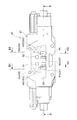
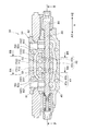
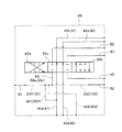
図1乃至図5に示す本実施の形態にかかる方向切換弁30は、スプール孔33が形成された弁本体31と、スプール孔33に挿入されたスプール80と、複数の通路(41,42,45,51,52,53,61,62(以下、(41〜62)と記す。))と、通路(101,102,301,302)を形成可能な複数の領域(201,202,401,402)と、チェック弁又は盲栓を設けるための規制部材設置部(701〜704)を形成可能な複数の領域(711〜714)と、を備える。   The direction switching valve 30 according to the present embodiment shown in FIGS. 1 to 5 includes a valve body 31 in which a spool hole 33 is formed, a spool 80 inserted in the spool hole 33, and a plurality of passages (41, 42, 45, 51, 52, 53, 61 (hereinafter referred to as (41-62)) and a plurality of regions (201, 202, 401, 402) and a plurality of regions (711 to 714) capable of forming restriction member installation portions (701 to 704) for providing check valves or blind plugs.

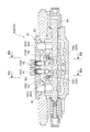
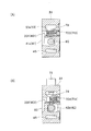
説明の便宜上、通路(101,102,301,302)を形成可能な複数の領域(201,202,401,402)のうちの通路(201,202)は、図2において、二点鎖線で囲まれている。通路(401,402)は、図1乃至図3において、二点鎖線で囲まれている。図5において領域(201,202,401,402)に対応する部分は、二点鎖線で示されている。また、規制部材設置部(701〜704)を形成可能な複数の領域(711〜714)のうちの領域(711,712)は、図2において、一点鎖線で囲まれている。領域(713,714)は、図3において、一点鎖線で囲まれている。   For convenience of explanation, the passages (201, 202) among the plurality of regions (201, 202, 401, 402) which can form the passages (101, 102, 301, 302) are surrounded by a two-dot chain line in FIG. It is. The passages (401, 402) are surrounded by a two-dot chain line in FIGS. In FIG. 5, portions corresponding to the regions (201, 202, 401, 402) are indicated by two-dot chain lines. Moreover, the area | region (711,712) of the some area | regions (711-714) which can form a control member installation part (701-704) is enclosed with the dashed-dotted line in FIG. The region (713, 714) is surrounded by a one-dot chain line in FIG.

この方向切換弁30は、建設機械用油圧回路(図示なし)に適用される方向切換弁である。方向切換弁30は、建設機械用油圧回路において、ポンプ(図示せず)とアクチュエータ(図示)とに接続され、アクチュエータに対して油を供排(供給および排出)するための弁である。   The direction switching valve 30 is a direction switching valve applied to a construction machine hydraulic circuit (not shown). The directional control valve 30 is a valve connected to a pump (not shown) and an actuator (shown) in the construction machine hydraulic circuit for supplying and discharging oil to the actuator.

上記の領域(201,202,401,402)において形成可能な通路(101,102,301,302)は、ポンプの吐出油を、アクチュエータに供給するための通路である。この方向切換弁30は、複数の領域(201,202,401,402)の少なくともいずれかにおいて通路(101,102,301,302)が形成された場合に、アクチュエータに対して油を供排(供給および排出)することが可能となる。   The passages (101, 102, 301, 302) that can be formed in the above regions (201, 202, 401, 402) are passages for supplying pump discharge oil to the actuator. The direction switching valve 30 drains oil to the actuator when the passage (101, 102, 301, 302) is formed in at least one of the plurality of regions (201, 202, 401, 402). Supply and discharge).

すなわち、図1乃至図5に示す方向切換弁30は、油圧回路に適用されて適切に油を切り換える方向切換弁を製造するための中間体(ベース体あるいはベース部材)とも言える。この方向切換弁30は、上記のような複数の領域(201,202,401,402)を備えることにより、ポンプからアクチュエータに供給するための複数種類の通路パターンを、選択的に形成することが可能となっている。   That is, the direction switching valve 30 shown in FIGS. 1 to 5 can be said to be an intermediate body (base body or base member) for manufacturing a direction switching valve that is applied to a hydraulic circuit and appropriately switches oil. The direction switching valve 30 includes a plurality of regions (201, 202, 401, 402) as described above, so that a plurality of types of passage patterns for supplying the actuator from the pump can be selectively formed. It is possible.

方向切換弁30が接続されるアクチュエータは、建設機械を作動させる油圧アクチュエータである。この方向切換弁30が接続可能なアクチュエータの種類には、油圧モータと、油圧シリンダと、がある。方向切換弁30が接続されるアクチュエータは、第1ポートと、第2ポートと、を備えるアクチュエータである。第1ポートおよび第2ポートのそれぞれは、アクチュエータに対する油の供排口(供給口および排出口)である。このようなアクチュエータは、第1ポートに油が供給され、かつ、第2ポートから油が排出されることにより、一方側に作動する。具体的には例えば、油圧シリンダが伸びる、また例えば、油圧モータが一方側に回転する。第2ポートに油が供給され、かつ、第1ポートから油が排出されることにより、アクチュエータは他方側(上記「一方側」とは逆側)に作動する。具体的には例えば、油圧シリンダが縮む、また例えば、油圧モータが他方側に回転する。方向切換弁30は、このようなアクチュエータに後述するアクチュエータ通路(61・62)を介して接続されることが想定されている。   The actuator to which the direction switching valve 30 is connected is a hydraulic actuator that operates the construction machine. The types of actuators that can be connected to the direction switching valve 30 include a hydraulic motor and a hydraulic cylinder. The actuator to which the direction switching valve 30 is connected is an actuator that includes a first port and a second port. Each of the first port and the second port is an oil supply / discharge port (supply port and discharge port) for the actuator. Such an actuator operates on one side by supplying oil to the first port and discharging oil from the second port. Specifically, for example, the hydraulic cylinder extends, and for example, the hydraulic motor rotates to one side. When oil is supplied to the second port and oil is discharged from the first port, the actuator operates on the other side (the side opposite to the above "one side"). Specifically, for example, the hydraulic cylinder contracts, and for example, the hydraulic motor rotates to the other side. The direction switching valve 30 is assumed to be connected to such an actuator via an actuator passage (61, 62) described later.

この方向切換弁30は、スプール孔33に対するスプール80の位置(ストローク位置)に応じて、油の方向などを変えるスプール弁である。方向切換弁30は、スプール80のストローク位置に応じて、切換位置を切り換える。方向切換弁30の切換位置には、中立位置30a(図2、図4および図5に示す位置)と、中立位置30aから図中の右側に移動した第1作動位置30b(図5参照)と、中立位置30aから図中の左側に移動した第2作動位置30c(図5参照)と、がある。   The direction switching valve 30 is a spool valve that changes the direction of oil or the like according to the position (stroke position) of the spool 80 with respect to the spool hole 33. The direction switching valve 30 switches the switching position according to the stroke position of the spool 80. The switching position of the direction switching valve 30 includes a neutral position 30a (the position shown in FIGS. 2, 4 and 5), and a first operating position 30b (see FIG. 5) moved from the neutral position 30a to the right side in the drawing. And a second operating position 30c (see FIG. 5) moved from the neutral position 30a to the left side in the figure.

弁本体31は、スプール孔33、通路(41〜62)、領域(201,202,401,402)および領域(711〜714)が形成される部分である。弁本体31は、ブロック状(塊状)である。   The valve body 31 is a portion where the spool hole 33, the passages (41 to 62), the regions (201, 202, 401, 402), and the regions (711 to 714) are formed. The valve body 31 is block-like (bulk).

スプール孔33は、弁本体31(の内部)に形成される。スプール孔33は、スプール80を差し込み可能な孔である。スプール80は、着脱可能に、スプール孔33に挿入される。   The spool hole 33 is formed in (the inside of) the valve body 31. The spool hole 33 is a hole into which the spool 80 can be inserted. The spool 80 is detachably inserted into the spool hole 33.

複数の通路(41〜62)の各々は、油が流れる流路(油路、配管)である。複数の通路(41〜62)の各々は、弁本体31(の内部)に形成される。複数の通路(41〜62)のうちの通路(41,42,45,53,61,62)は、スプール孔33に開口する。スプール孔33に開口する通路(41,42,45,53,61,62)のスプール孔33への開口は、例えばスプール孔33の周方向に延びる。複数の通路(41〜62)のうちの通路(41,42,45,61,62)は、弁本体31の外部と連通するように、弁本体31の表面に開口する。また、複数の通路(41〜62)のうちの通路(51,52)も、弁本体31の外部と連通するように、弁本体31の表面に開口する。複数の通路(41〜62)には、アンロード通路(41・42)と、タンク通路45と、供給通路(51・52)と、ブリッジ通路53と、アクチュエータ通路(61・62)と、がある。   Each of the plurality of passages (41 to 62) is a flow path (oil path, piping) through which oil flows. Each of the plurality of passages (41 to 62) is formed in (inside) the valve body 31. Of the plurality of passages (41 to 62), the passages (41, 42, 45, 53, 61, 62) open to the spool hole 33. The opening to the spool hole 33 of the passage (41, 42, 45, 53, 61, 62) that opens to the spool hole 33 extends in the circumferential direction of the spool hole 33, for example. The passages (41, 42, 45, 61, 62) among the plurality of passages (41 to 62) open to the surface of the valve body 31 so as to communicate with the outside of the valve body 31. Further, the passages (51, 52) among the plurality of passages (41 to 62) also open to the surface of the valve body 31 so as to communicate with the outside of the valve body 31. The plurality of passages (41-62) include an unload passage (41, 42), a tank passage 45, a supply passage (51, 52), a bridge passage 53, and an actuator passage (61, 62). is there.

アンロード通路(41・42)は、ポンプの吐出油を、アクチュエータに供給せずに、タンクに戻すための通路(バイパス通路)である。但し、例えばアンロード通路(41・42)から他の通路が分岐する場合(図示なし)は、アンロード通路(41・42)からアクチュエータに油が供給されてもよい。アンロード通路(41・42)は、2本設けられる(いわばデュアルバイパスである)。アンロード通路(41・42)は、第1アンロード通路41と、第2アンロード通路42と、を備える。   The unloading passages (41 and 42) are passages (bypass passages) for returning the pump discharge oil to the tank without supplying the oil to the actuator. However, for example, when another passage branches from the unload passage (41, 42) (not shown), oil may be supplied from the unload passage (41, 42) to the actuator. Two unload passages (41, 42) are provided (so-called dual bypass). The unload passage (41, 42) includes a first unload passage 41 and a second unload passage 42.

第1アンロード通路41と第2アンロード通路42とは、方向切換弁30が油圧回路に適用された場合に、互いに異なるポンプに接続される通路である。以下、第1アンロード通路41が接続されるポンプを第1ポンプ(図示せず)と呼ぶ。第2アンロード通路42が接続されるポンプを第2ポンプ(図示せず)と呼ぶ。   The first unload passage 41 and the second unload passage 42 are passages connected to different pumps when the direction switching valve 30 is applied to a hydraulic circuit. Hereinafter, the pump to which the first unload passage 41 is connected is referred to as a first pump (not shown). The pump to which the second unload passage 42 is connected is called a second pump (not shown).

第1アンロード通路41は、第1ポンプに接続される通路である。第1アンロード通路41は、タンクに接続される通路である。第1アンロード通路41は、上流側第1アンロード通路41aと、下流側第2アンロード通路42bと、を備える。上流側第1アンロード通路41aは、第1アンロード通路41のうち、スプール孔33よりも上流側(第1ポンプ側)の通路である。下流側第1アンロード通路41bは、第1アンロード通路41のうち、スプール孔33よりも下流側(タンク側)の通路である。   The first unloading passage 41 is a passage connected to the first pump. The first unloading passage 41 is a passage connected to the tank. The first unload passage 41 includes an upstream first unload passage 41a and a downstream second unload passage 42b. The upstream first unloading passage 41 a is a passage on the upstream side (first pump side) of the first unloading passage 41 with respect to the spool hole 33. The downstream first unloading passage 41 b is a passage on the downstream side (tank side) of the first unloading passage 41 with respect to the spool hole 33.

第2アンロード通路42は、第1アンロード通路41が接続する第1ポンプとは異なる第2ポンプに接続される通路である。第2アンロード通路42は、タンクに接続される通路である。第2アンロード通路42は、上流側第2アンロード通路42aと、下流側第2アンロード通路42bと、を備える。上流側第2アンロード通路42aは、第2アンロード通路42のうち、スプール孔33よりも上流側(第2ポンプ側)の通路である。下流側第2アンロード通路42bは、第2アンロード通路42のうち、スプール孔33よりも下流側(タンク側)の通路である。   The second unload passage 42 is a passage connected to a second pump different from the first pump to which the first unload passage 41 is connected. The second unloading passage 42 is a passage connected to the tank. The second unload passage 42 includes an upstream second unload passage 42a and a downstream second unload passage 42b. The upstream second unloading passage 42 a is a passage on the upstream side (second pump side) of the second unloading passage 42 with respect to the spool hole 33. The downstream second unloading passage 42 b is a passage on the downstream side (tank side) of the second unloading passage 42 than the spool hole 33.

タンク通路45は、タンク(図示せず)に接続される通路である。タンク通路45は、アクチュエータから排出された油をタンクに戻すための通路である。   The tank passage 45 is a passage connected to a tank (not shown). The tank passage 45 is a passage for returning the oil discharged from the actuator to the tank.

供給通路(51・52)は、ポンプの吐出油を、アクチュエータに供給するための通路である。供給通路(51・52)は、第1供給通路51と、第2供給通路52と、を備える。   The supply passages (51, 52) are passages for supplying pump discharge oil to the actuator. The supply passages (51, 52) include a first supply passage 51 and a second supply passage 52.

第1供給通路51は、ポンプに接続可能な通路である。なお、第1供給通路51は、ポンプに接続されなくてもよい。第1供給通路51は、スプール孔33に直接的に開口していない。第1供給通路51は、ポンプに接続される場合、第1アンロード通路41が接続する第1ポンプに接続される。第1供給通路51は、第1ポンプに接続される場合、第1ポンプの吐出油を、アクチュエータに供給するために、受け入れる。第1供給通路51は、第1ポンプに接続される場合、第1アンロード通路41(上流側第1アンロード通路41a)に接続されてもよい。言い換えると、第1供給通路51は、第1アンロード通路41を介して第1ポンプに接続されてもよい。この場合、第1供給通路51の第1アンロード通路41への接続は、方向切換弁30の外部で行われる。   The first supply passage 51 is a passage that can be connected to the pump. The first supply passage 51 may not be connected to the pump. The first supply passage 51 does not open directly to the spool hole 33. When the first supply passage 51 is connected to the pump, the first supply passage 51 is connected to the first pump to which the first unload passage 41 is connected. When connected to the first pump, the first supply passage 51 receives the discharge oil of the first pump to supply the actuator. When the first supply passage 51 is connected to the first pump, the first supply passage 51 may be connected to the first unload passage 41 (upstream first unload passage 41a). In other words, the first supply passage 51 may be connected to the first pump via the first unload passage 41. In this case, the connection of the first supply passage 51 to the first unload passage 41 is performed outside the direction switching valve 30.

第2供給通路52は、ポンプに接続可能な通路である。なお、第2供給通路52は、ポンプに接続されなくてもよい。第2供給通路52は、スプール孔33に直接的に開口していない。第2供給通路52は、ポンプに接続される場合、第2アンロード通路42が接続する第2ポンプに接続される。第2供給通路52は、第2ポンプに接続される場合、第2ポンプの吐出油を、アクチュエータに供給するために、受け入れる。第2供給通路52は、第2ポンプに接続される場合、第2アンロード通路42(上流側第2アンロード通路42a)に接続されてもよい。言い換えると、第2供給通路52は、第2アンロード通路42を介して第2ポンプに接続されてもよい。この場合、第2供給通路52の第2アンロード通路42への接続は、方向切換弁30の外部で行われる。   The second supply passage 52 is a passage connectable to the pump. The second supply passage 52 may not be connected to the pump. The second supply passage 52 does not open directly to the spool hole 33. When the second supply passage 52 is connected to the pump, the second supply passage 52 is connected to the second pump to which the second unload passage 42 is connected. When the second supply passage 52 is connected to the second pump, the second supply passage 52 receives the discharged oil of the second pump to supply the actuator. When the second supply passage 52 is connected to the second pump, the second supply passage 52 may be connected to the second unloading passage 42 (the upstream second unloading passage 42a). In other words, the second supply passage 52 may be connected to the second pump via the second unload passage 42. In this case, the connection of the second supply passage 52 to the second unload passage 42 is performed outside the direction switching valve 30.

ブリッジ通路53は、複数の領域(201,202,401,402)の少なくともいずれかにおいて通路(101,102,301,302)が形成された場合に、第1ポンプおよび第2ポンプのうちの少なくともいずれかからの吐出油を、アクチュエータに供給するための通路である。図2に示すように、ブリッジ通路53は、第1ブリッジ通路53aと、第2ブリッジ通路53bと、を備える。第1ブリッジ通路53aは、第1ポンプおよび第2ポンプのうちの少なくともいずれかからの吐出油を、第1アクチュエータ通路61(下記)に供給するための通路である。第2ブリッジ通路53bは、第1ポンプおよび第2ポンプのうちの少なくともいずれかからの吐出油を、第2アクチュエータ通路62(下記)に供給するための通路である。   The bridge passage 53 is at least one of the first pump and the second pump when the passage (101, 102, 301, 302) is formed in at least one of the plurality of regions (201, 202, 401, 402). It is a passage for supplying the discharge oil from either to the actuator. As shown in FIG. 2, the bridge passage 53 includes a first bridge passage 53a and a second bridge passage 53b. The first bridge passage 53a is a passage for supplying discharged oil from at least one of the first pump and the second pump to the first actuator passage 61 (described below). The second bridge passage 53b is a passage for supplying discharged oil from at least one of the first pump and the second pump to the second actuator passage 62 (described below).

アクチュエータ通路(61・62)は、複数の領域(201,202,401,402)の少なくともいずれかにおいて通路(101,102,301,302)が形成された場合に、第1ポンプおよび第2ポンプのうちの少なくともいずれかからの吐出油を、ブリッジ通路53を介して、アクチュエータに供給するための通路である。アクチュエータ通路(61・62)は、アクチュエータに接続される。アクチュエータ通路(61・62)は、上述した第1アクチュエータ通路61と、第2アクチュエータ通路62と、を備える。   The actuator passage (61/62) is configured such that when the passage (101, 102, 301, 302) is formed in at least one of the plurality of regions (201, 202, 401, 402), the first pump and the second pump This is a passage for supplying discharged oil from at least one of the actuators to the actuator via the bridge passage 53. The actuator passage (61, 62) is connected to the actuator. The actuator passages (61, 62) include the first actuator passage 61 and the second actuator passage 62 described above.

第1アクチュエータ通路61は、アクチュエータの第1ポートに接続される通路である。第2アクチュエータ通路62は、アクチュエータの第2ポートに接続される通路である。   The first actuator passage 61 is a passage connected to a first port of the actuator. The second actuator passage 62 is a passage connected to the second port of the actuator.

領域(201,202,401,402)は、第1ポンプおよび第2ポンプのうちの少なくともいずれかの吐出油を、アクチュエータに供給するための通路(101,102,301,302)を形成するための領域である。領域(201,202,401,402)には、第1パラレル用領域201、第2パラレル用領域202、第1タンデム用領域401および第2タンデム用領域402がある。   The region (201, 202, 401, 402) forms a passage (101, 102, 301, 302) for supplying the discharge oil of at least one of the first pump and the second pump to the actuator. It is an area. The areas (201, 202, 401, 402) include a first parallel area 201, a second parallel area 202, a first tandem area 401, and a second tandem area 402.

第1パラレル用領域201は、第1供給通路51とブリッジ通路53とを接続する第1パラレル通路101を形成可能な領域である。第2パラレル用領域202は、第2供給通路52とブリッジ通路53とを接続する第2パラレル通路102を形成可能な領域である。   The first parallel region 201 is a region where the first parallel passage 101 that connects the first supply passage 51 and the bridge passage 53 can be formed. The second parallel area 202 is an area in which the second parallel passage 102 connecting the second supply passage 52 and the bridge passage 53 can be formed.

第1タンデム用領域401は、第1アンロード通路41とブリッジ通路53とを接続する第1タンデム通路301を形成可能な領域である。第1タンデム通路301は、第1アンロード通路41とブリッジ通路53とを方向切換弁30の内部で接続するものでもよい。第1タンデム通路301は、第1アンロード通路41とブリッジ通路53とを方向切換弁30の外部で接続するものでもよい。図5に示すように、本実施の形態では、第1タンデム通路301は、形成された場合に、第1アンロード通路41とブリッジ通路53とを方向切換弁30の内部で接続するものである。第2タンデム用領域402は、第2アンロード通路42とブリッジ通路53とを接続する第2タンデム通路302を形成可能な領域である。第2タンデム通路302は、第2アンロード通路42とブリッジ通路53とを方向切換弁30の内部で接続するものでもよい。第2タンデム通路302は、第2アンロード通路42とブリッジ通路53とを方向切換弁30の外部で接続するものでもよい。図5に示すように、本実施の形態では、第2タンデム通路302は、形成された場合に、第2アンロード通路42とブリッジ通路53とを方向切換弁30の外部で接続するものである。   The first tandem area 401 is an area in which a first tandem passage 301 connecting the first unloading passage 41 and the bridge passage 53 can be formed. The first tandem passage 301 may connect the first unloading passage 41 and the bridge passage 53 inside the direction switching valve 30. The first tandem passage 301 may connect the first unloading passage 41 and the bridge passage 53 outside the direction switching valve 30. As shown in FIG. 5, in the present embodiment, when the first tandem passage 301 is formed, the first unload passage 41 and the bridge passage 53 are connected inside the direction switching valve 30. . The second tandem area 402 is an area capable of forming a second tandem passage 302 connecting the second unloading passage 42 and the bridge passage 53. The second tandem passage 302 may connect the second unloading passage 42 and the bridge passage 53 inside the direction switching valve 30. The second tandem passage 302 may connect the second unloading passage 42 and the bridge passage 53 outside the direction switching valve 30. As shown in FIG. 5, in the present embodiment, when formed, the second tandem passage 302 connects the second unloading passage 42 and the bridge passage 53 outside the direction switching valve 30. .

第1パラレル用領域201に第1パラレル通路101が形成された場合に、ブリッジ通路53は、第1供給通路51に接続される。第2パラレル用領域202に第2パラレル通路102が形成された場合に、ブリッジ通路53は、第2供給通路52に接続される。第1パラレル用領域201に第1パラレル通路101が形成され、第2パラレル用領域202に第2パラレル通路102が形成された場合に、ブリッジ通路53は、第1供給通路51および第2供給通路52に接続される。   When the first parallel passage 101 is formed in the first parallel area 201, the bridge passage 53 is connected to the first supply passage 51. When the second parallel passage 102 is formed in the second parallel area 202, the bridge passage 53 is connected to the second supply passage 52. When the first parallel passage 101 is formed in the first parallel region 201 and the second parallel passage 102 is formed in the second parallel region 202, the bridge passage 53 includes the first supply passage 51 and the second supply passage. 52.

第1パラレル用領域201に第1パラレル通路101が形成され、第1供給通路51が第1ポンプに接続される場合には、ブリッジ通路53には、第1供給通路51を流れる油が流れることが可能となる。第2パラレル用領域202に第2パラレル通路102が形成され、第2供給通路52が第2ポンプに接続される場合には、ブリッジ通路53には、第2供給通路52を流れる油が流れることが可能となる。第1パラレル用領域201に第1パラレル通路101が形成され、第1供給通路51が第1ポンプに接続され、第2パラレル用領域202に第2パラレル通路102が形成され、第2供給通路52が第2ポンプに接続される場合には、ブリッジ通路53には、第1供給通路51を流れる油と第2供給通路52を流れる油とが合流した油が流れることが可能となる。   In the case where the first parallel passage 101 is formed in the first parallel area 201 and the first supply passage 51 is connected to the first pump, the oil flowing in the first supply passage 51 flows in the bridge passage 53. Is possible. In the case where the second parallel passage 102 is formed in the second parallel region 202 and the second supply passage 52 is connected to the second pump, oil flowing in the second supply passage 52 flows in the bridge passage 53. Is possible. A first parallel passage 101 is formed in the first parallel region 201, a first supply passage 51 is connected to the first pump, a second parallel passage 102 is formed in the second parallel region 202, and a second supply passage 52 is formed. When it is connected to the second pump, it becomes possible for the bridge passage 53 to flow the combined oil of the oil flowing through the first supply passage 51 and the oil flowing through the second supply passage 52.

第1タンデム用領域401に第1タンデム通路301が形成された場合に、ブリッジ通路53は、第1アンロード通路41に接続される。第2タンデム用領域402に第2タンデム通路302が形成された場合に、ブリッジ通路53は、第2アンロード通路42に接続される。第1タンデム用領域401に第1タンデム通路301が形成され、第2タンデム用領域402に第2タンデム通路302が形成された場合に、ブリッジ通路53は、第1アンロード通路41および第2アンロード通路42に接続される。   When the first tandem passage 301 is formed in the first tandem region 401, the bridge passage 53 is connected to the first unload passage 41. When the second tandem passage 302 is formed in the second tandem area 402, the bridge passage 53 is connected to the second unloading passage 42. When the first tandem passage 301 is formed in the first tandem region 401 and the second tandem passage 302 is formed in the second tandem region 402, the bridge passage 53 includes the first unloading passage 41 and the second unloading passage 41. Connected to the load passage 42.

第1タンデム用領域401に第1タンデム通路301が形成される場合には、ブリッジ通路53には、第1アンロード通路41を流れる油が流れることが可能となる。第2タンデム用領域402に第2タンデム通路302が形成される場合には、ブリッジ通路53には、第2アンロード通路42を流れる油が流れることが可能となる。第1タンデム用領域401に第1タンデム通路301が形成され、第2タンデム用領域402に第2タンデム通路302が形成される場合には、ブリッジ通路53には、第1アンロード通路41を流れる油と第2第2アンロード通路42を流れる油とが合流した油が流れることが可能となる。   In the case where the first tandem passage 301 is formed in the first tandem area 401, the oil flowing through the first unloading passage 41 can flow through the bridge passage 53. When the second tandem passage 302 is formed in the second tandem region 402, oil flowing through the second unload passage 42 can flow through the bridge passage 53. When the first tandem passage 301 is formed in the first tandem region 401 and the second tandem passage 302 is formed in the second tandem region 402, the bridge passage 53 flows through the first unloading passage 41. It becomes possible for the oil, which is a combination of the oil and the oil flowing through the second second unload passage 42, to flow.

また、第1パラレル用領域201に第1パラレル通路101が形成され、第1供給通路51が第1ポンプに接続され、第1タンデム用領域401に第1タンデム通路301が形成される場合には、ブリッジ通路53には、第1供給通路51を流れる油と第1アンロード通路41を流れる油とが合流した油が流れることが可能となる。   When the first parallel passage 101 is formed in the first parallel region 201, the first supply passage 51 is connected to the first pump, and the first tandem passage 301 is formed in the first tandem region 401, The bridge passage 53 can flow oil in which the oil flowing through the first supply passage 51 and the oil flowing through the first unloading passage 41 are combined.

第2パラレル用領域202に第2パラレル通路102が形成され、第2供給通路52が第2ポンプに接続され、第2タンデム用領域402に第2タンデム通路302が形成される場合には、ブリッジ通路53には、第2供給通路52を流れる油と第2アンロード通路42を流れる油とが合流した油が流れることが可能となる。   When the second parallel passage 102 is formed in the second parallel region 202, the second supply passage 52 is connected to the second pump, and the second tandem passage 302 is formed in the second tandem region 402, the bridge In the passage 53, oil in which the oil flowing through the second supply passage 52 and the oil flowing through the second unloading passage 42 join can flow.

第1パラレル用領域201に第1パラレル通路101が形成され、第1供給通路51が第1ポンプに接続され、第1タンデム用領域401に第1タンデム通路301が形成され、第2パラレル用領域202に第2パラレル通路102が形成され、第2供給通路52が第2ポンプに接続され、第2タンデム用領域402に第2タンデム通路302が形成される場合には、ブリッジ通路53には、第1供給通路51を流れる油と第1アンロード通路41を流れる油とが合流した油、および、第2供給通路52を流れる油と第2アンロード通路42を流れる油とが合流した油が流れることが可能となる。なお、第1パラレル通路101、第2パラレル通路102、第1タンデム通路301および第2タンデム通路302の一以上が形成された場合のブリッジ通路53に対する油の流入パターンは、上記以外のパターンも存在する。   A first parallel passage 101 is formed in the first parallel region 201, the first supply passage 51 is connected to the first pump, a first tandem passage 301 is formed in the first tandem region 401, and a second parallel region When the second parallel passage 102 is formed in 202, the second supply passage 52 is connected to the second pump, and the second tandem passage 302 is formed in the second tandem region 402, the bridge passage 53 includes: Oil in which the oil flowing in the first supply passage 51 and the oil flowing in the first unload passage 41 merge, and the oil in which the oil flowing in the second supply passage 52 and the oil flowing in the second unload passage 42 merge. It becomes possible to flow. The oil inflow pattern to the bridge passage 53 when one or more of the first parallel passage 101, the second parallel passage 102, the first tandem passage 301, and the second tandem passage 302 are formed includes patterns other than those described above. To do.

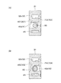
図2および図3に示すように、領域(711〜714)は、チェック弁又は盲栓を設けるための規制部材設置部(701〜704)を形成するための領域である。領域(711〜714)には、第1規制部材設置部701を形成可能な第1規制部材用領域711、第2規制部材設置部702を形成可能な第2規制部材用領域712、第3規制部材設置部703を形成可能な第3規制部材用領域713および第4規制部材設置部704を形成可能な第4規制部材用領域714がある。   As shown in FIGS. 2 and 3, the regions (711 to 714) are regions for forming restricting member installation portions (701 to 704) for providing check valves or blind plugs. The regions (711 to 714) include a first restricting member region 711 capable of forming the first restricting member installing portion 701, a second restricting member region 712 capable of forming the second restricting member installing portion 702, and a third restricting member. There is a third restricting member region 713 capable of forming the member installing portion 703 and a fourth restricting member region 714 capable of forming the fourth restricting member installing portion 704.

図2に示すように、第1規制部材用領域711は、第1パラレル用領域201に第1パラレル通路101が形成された場合に、第1パラレル通路101とブリッジ通路53との間にチェック弁または盲栓を設けることが可能な第1規制部材設置部701を形成するための領域である。第1規制部材用領域711に形成される第1規制部材設置部701は、第1パラレル用領域201に第1パラレル通路101が形成された場合に、ブリッジ通路53から第1パラレル通路101への油の逆流を防ぐチェック弁を設ける部分として機能する。第1規制部材設置部701は、例えば第1パラレル用領域201に形成された第1パラレル通路101が不要となった場合に、ブリッジ通路53と第1パラレル通路101との連通を遮断する盲栓を設ける部分として機能する。   As shown in FIG. 2, the first restricting member region 711 has a check valve between the first parallel passage 101 and the bridge passage 53 when the first parallel passage 101 is formed in the first parallel region 201. Or it is an area | region for forming the 1st control member installation part 701 which can provide a blind plug. When the first parallel passage 101 is formed in the first parallel area 201, the first restriction member installation portion 701 formed in the first restriction member area 711 is connected from the bridge path 53 to the first parallel path 101. It functions as a part where a check valve is provided to prevent backflow of oil. The first restricting member installation portion 701 is a blind plug that blocks communication between the bridge passage 53 and the first parallel passage 101 when the first parallel passage 101 formed in the first parallel region 201 is not required, for example. It functions as a part to provide.

第2規制部材用領域712は、第2パラレル用領域202に第2パラレル通路102が形成された場合に、第2パラレル通路102とブリッジ通路53との間にチェック弁または盲栓を設けることが可能な第2規制部材設置部702を形成するための領域である。第2規制部材用領域712に形成される第2規制部材設置部702は、第2パラレル用領域202に第1パラレル通路102が形成された場合に、ブリッジ通路53から第2パラレル通路102への油の逆流を防ぐチェック弁を設ける部分として機能する。第2規制部材設置部702は、例えば第2パラレル用領域202に形成された第2パラレル通路102が不要となった場合に、ブリッジ通路53と第2パラレル通路102との連通を遮断する盲栓を設ける部分として機能する。   When the second parallel passage 102 is formed in the second parallel region 202, the second restriction member region 712 may provide a check valve or a blind plug between the second parallel passage 102 and the bridge passage 53. This is an area for forming a possible second restricting member installation portion 702. When the first parallel passage 102 is formed in the second parallel area 202, the second restriction member installation portion 702 formed in the second restriction member area 712 is formed from the bridge passage 53 to the second parallel passage 102. It functions as a part where a check valve is provided to prevent backflow of oil. The second restricting member installation portion 702 is a blind plug that blocks communication between the bridge passage 53 and the second parallel passage 102 when the second parallel passage 102 formed in the second parallel region 202 is not required, for example. It functions as a part to provide.

図3に示すように、第3規制部材用領域713は、第1タンデム用領域401に第1タンデム通路301が形成された場合に、第1タンデム通路301とブリッジ通路53との間にチェック弁または盲栓を設けることが可能な第3規制部材設置部703を形成するための領域である。第3規制部材用領域713に形成される第3規制部材設置部703は、第1タンデム用領域401に第1タンデム通路301が形成された場合に、ブリッジ通路53から第1タンデム通路301への油の逆流を防ぐチェック弁を設ける部分として機能する。第3規制部材設置部703は、例えば第1タンデム用領域401に形成された第1タンデム通路301が不要となった場合に、ブリッジ通路53と第1タンデム通路301との連通を遮断する盲栓を設ける部分として機能する。   As shown in FIG. 3, the third regulating member region 713 is a check valve between the first tandem passage 301 and the bridge passage 53 when the first tandem passage 301 is formed in the first tandem region 401. Or it is an area | region for forming the 3rd control member installation part 703 which can provide a blind plug. The third restricting member installation portion 703 formed in the third restricting member region 713 is formed from the bridge passage 53 to the first tandem passage 301 when the first tandem passage 301 is formed in the first tandem region 401. It functions as a part where a check valve is provided to prevent backflow of oil. The third restricting member installation portion 703 is a blind plug that blocks communication between the bridge passage 53 and the first tandem passage 301 when the first tandem passage 301 formed in the first tandem region 401 is not required, for example. It functions as a part to provide.

第4規制部材用領域714は、第2タンデム用領域402に第2タンデム通路302が形成された場合に、第2タンデム通路302とブリッジ通路53との間にチェック弁または盲栓を設けることが可能な第4規制部材設置部704を形成するための領域である。第4規制部材用領域714に形成される第4規制部材設置部704は、第2タンデム用領域402に第2タンデム通路302が形成された場合に、ブリッジ通路53から第2タンデム通路302への油の逆流を防ぐチェック弁を設ける部分として機能する。第4規制部材設置部704は、例えば第2タンデム用領域402に形成された第2タンデム通路401が不要となった場合に、ブリッジ通路53と第2タンデム通路302との連通を遮断する盲栓を設ける部分として機能する。   The fourth restricting member region 714 may provide a check valve or a blind plug between the second tandem passage 302 and the bridge passage 53 when the second tandem passage 302 is formed in the second tandem region 402. This is an area for forming a possible fourth restricting member installation portion 704. The fourth restricting member installation portion 704 formed in the fourth restricting member area 714 is formed from the bridge path 53 to the second tandem path 302 when the second tandem path 302 is formed in the second tandem area 402. It functions as a part where a check valve is provided to prevent backflow of oil. The fourth restricting member installation portion 704 is a blind plug that blocks communication between the bridge passage 53 and the second tandem passage 302 when, for example, the second tandem passage 401 formed in the second tandem region 402 becomes unnecessary. It functions as a part to provide.

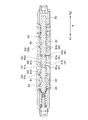
スプール80は、図2および図4に示すように、スプール孔33に挿入される。スプール80は、略円柱状である。スプール80の軸方向(略円柱の中心軸の方向)を、スプール軸方向Aとする。スプール軸方向Aにおける一方側を一方側A1、他方側を他方側A2とする。スプール80は、スプール孔33に対してスプール軸方向Aにスライド(ストローク)自在である。   As shown in FIGS. 2 and 4, the spool 80 is inserted into the spool hole 33. The spool 80 is substantially cylindrical. The axial direction of the spool 80 (the direction of the central axis of the substantially cylinder) is defined as the spool axial direction A. One side in the spool axial direction A is one side A1, and the other side is the other side A2. The spool 80 can slide (stroke) in the spool axial direction A with respect to the spool hole 33.

スプール80は、通路どうし(例えば、ブリッジ通路53とアクチュエータ通路(61・62))の接続および遮断を切り換える。このスプール80は、通路どうしの接続の有無、および、接続の開度(弁開度)を切り換える。さらに詳しくは、スプール80は、通路どうしを「遮断状態」ならびに「接続状態」(「全開状態」および「絞り状態」)のいずれかの状態にする。
「遮断状態」は、通路どうしが接続されていない状態(遮断された状態)である。
「接続状態」は、通路どうしが接続された状態(連通された状態)である。この「接続状態」には、「全開状態」と「絞り状態」とがある。
「全開状態」は、通路どうしの流路の開度が最大の状態(スプール80を一方側A1の端から他方側A2の端までストロークさせたときに開度が様々に変化するところ、この開度が最大の状態)である。例えば、「全開状態」は、通路どうしの流路が絞られていない状態である。
「絞り状態」は、通路どうしの流路が、上記「全開状態」よりも絞られた状態(遮断状態を除く)である。
The spool 80 switches connection and disconnection between the passages (for example, the bridge passage 53 and the actuator passage (61, 62)). The spool 80 switches the presence / absence of connection between the passages and the opening degree (valve opening degree) of the connection. More specifically, the spool 80 brings the passages into any one of a “blocking state” and a “connected state” (“fully open state” and “throttle state”).
The "blocked state" is a state in which the passages are not connected (blocked state).
The "connected state" is a state in which the passages are connected (connected). The "connected state" includes "full open state" and "squeezed state".
The “fully open state” is a state in which the opening degree of the flow path between the passages is maximum (the opening degree changes variously when the spool 80 is stroked from the end of the one side A1 to the end of the other side A2). The degree is the maximum). For example, in the “full open state”, the flow paths between the passages are not narrowed.
The “squeezed state” is a state where the flow path between the passages is narrower than the “fully open state” (excluding the shut-off state).

このスプール80は、複数の領域(201,202,401,402)に形成される通路(101,102,301,302)のパターンによって、異なる構成が採用される。具体的には、ブリッジ通路53に第1ポンプおよび第2ポンプの両方からの吐出油が流れるように通路(101,102,301,302)が形成された場合と、ブリッジ通路53に第1ポンプのみからの吐出油が流れるように通路(101,102,301,302)が形成された場合と、ブリッジ通路53に第2ポンプのみからの吐出油が流れるように通路(101,102,301,302)が形成された場合とで、異なる構成のスプールが用いられる。   The spool 80 has a different configuration depending on the pattern of the passages (101, 102, 301, 302) formed in the plurality of regions (201, 202, 401, 402). Specifically, when the passages (101, 102, 301, 302) are formed in the bridge passage 53 so that the discharge oil from both the first pump and the second pump flows, the first pump is provided in the bridge passage 53. When the passage (101, 102, 301, 302) is formed so that the discharge oil from only the flow can flow, and the passage (101, 102, 301, so that the discharge oil from the second pump only flows into the bridge passage 53). In the case where 302) is formed, spools of different configurations are used.

図1乃至図5に示すスプール80は、ブリッジ通路53に第1ポンプおよび第2ポンプの両方からの吐出油が流れるように通路(101,102,301,302)が形成された場合に用いられるスプールを示している。   The spool 80 shown in FIGS. 1 to 5 is used when the passages (101, 102, 301, 302) are formed in the bridge passage 53 so that the discharge oil from both the first pump and the second pump flows. Shows the spool.

<ブリッジ通路に第1ポンプおよび第2ポンプの両方からの吐出油が流れる構成の場合>
この場合、スプール80では、以下の構成が採用される。
スプール80は、ブリッジ通路53と、アクチュエータ通路(61・62)と、の接続および遮断を切り換える。
スプール80は、アクチュエータ通路(61・62)と、タンク通路45と、の接続および遮断を切り換える。
スプール80は、上流側第1アンロード通路41aと、下流側第1アンロード通路41bと、の接続および遮断を切り換える。
スプール80は、上流側第2アンロード通路42aと、下流側第2アンロード通路42bと、の接続および遮断を切り換える。
<When the configuration is such that discharge oil from both the first pump and the second pump flows into the bridge passage>
In this case, the spool 80 employs the following configuration.
The spool 80 switches connection and disconnection between the bridge passage 53 and the actuator passage (61, 62).
The spool 80 switches connection and disconnection between the actuator passage (61 and 62) and the tank passage 45.
The spool 80 switches connection and disconnection between the upstream first unload passage 41a and the downstream first unload passage 41b.
The spool 80 switches connection and disconnection between the upstream side second unload passage 42a and the downstream side second unload passage 42b.

スプール80は、図4に示すように、切欠き部81と、ランド部83と、を備える。切欠き部81とランド部83とは、スプール軸方向Aに交互に配置される(形成される)。   As shown in FIG. 4, the spool 80 includes a notch portion 81 and a land portion 83. The notches 81 and the lands 83 are alternately arranged (formed) in the spool axial direction A.

切欠き部81は、通路どうし(通路間)を接続させる。切欠き部81は、通路のスプール孔33への開口どうしを接続させる。以下、スプール孔33への開口を、「開口」という。なお、図示の例では、複数の通路(41〜62)のうちの通路(41,42,45,53,61,62)がスプール孔33へ開口する。切欠き部81は、通路どうしを、スプール孔33を介して接続させる。図4に示すように、切欠き部81は、ランド部83に対して、スプール80の径方向内側に凹む部分である。切欠き部81は、複数設けられ、例えば4か所設けられる(2か所、3か所、または5か所以上設けられてもよい)。切欠き部81は、第1アンロード通路用切欠き部81aと、第2アンロード通路用切欠き部81bと、を備える。第1アンロード通路用切欠き部81aは、上流側第1アンロード通路41aと下流側第1アンロード通路41bとを接続させる。第2アンロード通路用切欠き部81bは、上流側第2アンロード通路42aと下流側第2アンロード通路42bとを接続させる。   The notches 81 connect the passages (between the passages). The notch 81 connects openings of the passage to the spool hole 33. Hereinafter, the opening to the spool hole 33 is referred to as "opening". In the illustrated example, the passages (41, 42, 45, 53, 61, 62) of the plurality of passages (41 to 62) open to the spool hole 33. The notch 81 connects the passages through the spool hole 33. As shown in FIG. 4, the notch portion 81 is a portion that is recessed inward in the radial direction of the spool 80 with respect to the land portion 83. A plurality of notches 81 are provided, for example, four places (two places, three places, or five or more places may be provided). The notch 81 includes a first unloading passage notch 81 a and a second unloading passage notch 81 b. The first unloading passage cutout portion 81a connects the upstream first unloading passage 41a and the downstream first unloading passage 41b. The second unloading passage notch portion 81 b connects the upstream second unloading passage 42 a and the downstream second unloading passage 42 b.

ランド部83は、通路どうしが接続されない状態(遮断状態)にする。ランド部83は、切欠き部81による通路どうしの接続が行われないようにする。ランド部83は、スプール孔33(の内面)に接触する。ランド部83は、通路(41,42,45,53,61,62)の開口を塞ぐ。または、ランド部83は、通路どうしの間のスプール孔33を塞ぐ。ランド部83は、通路どうしを絞り状態にする。ランド部83は、通路(41,42,45,53,61,62)の開口を、全開状態よりも狭くする。ランド部83は、複数設けられ、例えば5か所設けられる(4か所以下、または6か所以上設けられてもよい)。ランド部83は、アンロード通路用ランド部(83a〜83c)を備える。   The land portion 83 is in a state in which the passages are not connected (blocked state). The land portion 83 prevents the passages from being connected to each other by the notch portion 81. The land portion 83 contacts (the inner surface of) the spool hole 33. The land portion 83 closes the opening of the passage (41, 42, 45, 53, 61, 62). Alternatively, the land portion 83 closes the spool hole 33 between the passages. The land portion 83 squeezes the passages. The land part 83 makes the opening of the passage (41, 42, 45, 53, 61, 62) narrower than the fully opened state. A plurality of land portions 83 are provided, for example, 5 locations (4 locations or less, or 6 locations or more may be provided). The land portion 83 includes unload passage land portions (83a to 83c).

アンロード通路用ランド部(83a〜83c)は、アンロード通路(41・42)を遮断可能である(遮断状態にすることが可能である)。アンロード通路用ランド部(83a〜83c)は、第1アンロード通路用ランド部83aと、第2アンロード通路用ランド部83bと、第3アンロード通路用ランド部83cと、を備える。   The unloading passage lands (83a to 83c) can shut off the unloading passages (41 and 42) (can be put in a shutoff state). The unload passage land portions (83a to 83c) include a first unload passage land portion 83a, a second unload passage land portion 83b, and a third unload passage land portion 83c.

第1アンロード通路用ランド部83aは、図4に示す中立位置30aから図中の右側に移動した第1作動位置30b(図5参照)のときに、第1アンロード通路41を遮断状態または絞り状態(図示なし)にする。第2アンロード通路用ランド部83bは、図4に示す中立位置30aから図中の左側に移動した第2作動位置30c(図5参照)のときに、第2アンロード通路42を遮断状態または絞り状態(図示なし)にする。   When the first unload passage land portion 83a is in the first operation position 30b (see FIG. 5) moved from the neutral position 30a shown in FIG. Set to the aperture state (not shown). The second unloading passage land portion 83b blocks the second unloading passage 42 when the second operation position 30c (see FIG. 5) is moved to the left in the figure from the neutral position 30a shown in FIG. Set to the aperture state (not shown).

第3アンロード通路用ランド部83cは、第1アンロード通路41を遮断可能、かつ、第2アンロード通路42を遮断可能である。この構成では、第3アンロード通路用ランド部83cが2つの用途に使われるため、ランド部を共通化できる。第3アンロード通路用ランド部83cは、第1作動位置30bのときに、第2アンロード通路42を遮断状態または絞り状態(図示なし)にする。第3アンロード通路用ランド部83cは、第2作動位置30cのときに、第1アンロード通路41を遮断状態または絞り状態(図示なし)にする。以上が、ブリッジ通路53に第1ポンプおよび第2ポンプの両方からの吐出油が流れる構成の場合のスプール80の構成である。ブリッジ通路53に第1ポンプおよび第2ポンプのうちのいずれかからの吐出油が流れる構成の場合は、スプール80は、以下の構成が採用される   The third unloading passage land 83 c can shut off the first unloading passage 41 and can shut off the second unloading passage 42. In this configuration, since the third unload passage land portion 83c is used for two purposes, the land portion can be shared. The third unloading passage land portion 83c brings the second unloading passage 42 into the blocking state or the throttling state (not shown) when in the first operation position 30b. The third unload passage land portion 83c puts the first unload passage 41 into a cut-off state or a throttled state (not shown) at the second operating position 30c. The above is the configuration of the spool 80 in the configuration in which the discharged oil from both the first pump and the second pump flows through the bridge passage 53. In the case where the discharge oil from either the first pump or the second pump flows into the bridge passage 53, the spool 80 adopts the following configuration.

<ブリッジ通路に第1ポンプのみからの吐出油が流れる構成の場合>
この場合、スプール80では、以下の構成が採用される。
スプール80は、ブリッジ通路53と、アクチュエータ通路(61・62)と、の接続および遮断を切り換える。
スプール80は、アクチュエータ通路(61・62)と、タンク通路45と、の接続および遮断を切り換える。
スプール80は、上流側第1アンロード通路41aと、下流側第1アンロード通路41bと、の接続および遮断を切り換える。
スプール80は、上流側第2アンロード通路42aと、下流側第2アンロード通路42bと、を常時、接続状態とする。
<In the case where the oil discharged from only the first pump flows through the bridge passage>
In this case, the spool 80 employs the following configuration.
The spool 80 switches connection and disconnection between the bridge passage 53 and the actuator passage (61, 62).
The spool 80 switches connection and disconnection between the actuator passage (61 and 62) and the tank passage 45.
The spool 80 switches connection and disconnection between the upstream first unload passage 41a and the downstream first unload passage 41b.
The spool 80 always connects the upstream second unload passage 42a and the downstream second unload passage 42b.

この場合、アンロード通路用ランド部(83a〜83c)が、以下のように機能する。   In this case, the unload passage land portions (83a to 83c) function as follows.

第1アンロード通路用ランド部83aは、図4に示す中立位置30aから図中の右側に移動した第1作動位置30b(図5参照)のときに、第1アンロード通路41を遮断状態または絞り状態(図示なし)にする。第2アンロード通路用ランド部83bは、図4に示す中立位置30aから図中の左側に移動した第2作動位置30c(図5参照)のときに、第2アンロード通路42を遮断状態または絞り状態にする機能を有さない(全開状態に維持する)。   When the first unload passage land portion 83a is in the first operation position 30b (see FIG. 5) moved from the neutral position 30a shown in FIG. Set to the aperture state (not shown). When the second unload passage land portion 83b is in the second operating position 30c (see FIG. 5) moved from the neutral position 30a shown in FIG. It does not have the function to bring it into a squeezed state (maintained in the fully open state).

第3アンロード通路用ランド部83cは、第1作動位置30bのときに、第2アンロード通路42を遮断状態または絞り状態にする機能を有さない(全開状態に維持する)。第3アンロード通路用ランド部83cは、第2作動位置30cのときに、第1アンロード通路41を遮断状態または絞り状態(図示なし)にする。   The third unloading passage land portion 83c does not have a function of bringing the second unloading passage 42 into the blocking state or the throttling state in the first operation position 30b (maintaining the second unloading passage 42 in the fully open state). The third unloading passage land portion 83c brings the first unloading passage 41 into the blocking state or the throttling state (not shown) when in the second operation position 30c.

その他の構成は、ブリッジ通路53に第1ポンプおよび第2ポンプの両方からの吐出油が流れる構成の場合と同様である。   Other configurations are the same as the configuration in which the discharge oil from both the first pump and the second pump flows through the bridge passage 53.

<ブリッジ通路に第2ポンプのみからの吐出油が流れる構成の場合>
この場合、スプール80では、以下の構成が採用される。
スプール80は、ブリッジ通路53と、アクチュエータ通路(61・62)と、の接続および遮断を切り換える。
スプール80は、アクチュエータ通路(61・62)と、タンク通路45と、の接続および遮断を切り換える。
スプール80は、上流側第1アンロード通路41aと、下流側第1アンロード通路41bと、を常時、接続状態とする。
スプール80は、上流側第2アンロード通路42aと、下流側第2アンロード通路42bと、の接続および遮断を切り換える。
<In the case where the discharge oil from only the second pump flows through the bridge passage>
In this case, the spool 80 employs the following configuration.
The spool 80 switches connection and disconnection between the bridge passage 53 and the actuator passage (61, 62).
The spool 80 switches connection and disconnection between the actuator passage (61 and 62) and the tank passage 45.
The spool 80 always connects the upstream first unload passage 41a and the downstream first unload passage 41b.
The spool 80 switches connection and disconnection between the upstream side second unload passage 42a and the downstream side second unload passage 42b.

この場合、アンロード通路用ランド部(83a〜83c)が、以下のように機能する。   In this case, the unload passage land portions (83a to 83c) function as follows.

第1アンロード通路用ランド部83aは、図4に示す中立位置30aから図中の右側に移動した第1作動位置30b(図5参照)のときに、第1アンロード通路41を遮断状態または絞り状態にする機能を有さない(全開状態に維持する)。第2アンロード通路用ランド部83bは、図4に示す中立位置30aから図中の左側に移動した第2作動位置30c(図5参照)のときに、第2アンロード通路42を遮断状態または絞り状態(図示なし)にする。   When the first unload passage land portion 83a is in the first operation position 30b (see FIG. 5) moved from the neutral position 30a shown in FIG. It does not have the function to bring it into a squeezed state (maintained in the fully open state). The second unloading passage land portion 83b blocks the second unloading passage 42 when the second operation position 30c (see FIG. 5) is moved to the left in the figure from the neutral position 30a shown in FIG. Set to the aperture state (not shown).

第3アンロード通路用ランド部83cは、第1作動位置30bのときに、第2アンロード通路42を遮断状態または絞り状態(図示なし)にする。第3アンロード通路用ランド部83cは、第2作動位置30cのときに、第1アンロード通路41を遮断状態または絞り状態にする機能を有さない(全開状態に維持する)。   The third unloading passage land portion 83c brings the second unloading passage 42 into the blocking state or the throttling state (not shown) when in the first operation position 30b. The third unloading passage land portion 83c does not have a function of bringing the first unloading passage 41 into the blocking state or the throttling state when in the second operating position 30c (maintaining a fully open state).

その他の構成は、ブリッジ通路53に第1ポンプおよび第2ポンプの両方からの吐出油が流れる構成の場合と同様である。   Other configurations are the same as the configuration in which the discharge oil from both the first pump and the second pump flows through the bridge passage 53.

(通路(41〜62)の配置)
図2に示す複数の通路(41〜62)のうちのスプール孔33に開口する通路(41,42,45,53,61,62)の開口(スプール孔33への開口)は、スプール軸方向Aの一方側A1から他方側A2の順に、例えば次の順に並ぶ。一方側A1のタンク通路45、第1アクチュエータ通路61、第1ブリッジ通路53a(一方側A1のブリッジ通路53)、アンロード通路(41・42)、第2ブリッジ通路53b(他方側A2のブリッジ通路53)、第2アクチュエータ通路62、他方側A2のタンク通路45。一方側A1のタンク通路45の開口と、他方側A2のタンク通路45の開口とは、弁本体31の内部で連通する(弁本体31の内部で連通しなくてもよい)。
(Arrangement of passages (41-62))
The openings (openings to the spool hole 33) of the passages (41, 42, 45, 53, 61, 62) that open to the spool hole 33 among the plurality of passages (41 to 62) shown in FIG. For example, the one side A1 to the other side A2 of A are arranged in the following order. One side A1 tank passage 45, first actuator passage 61, first bridge passage 53a (one side A1 bridge passage 53), unload passage (41, 42), second bridge passage 53b (the other side A2 bridge passage) 53), the second actuator passage 62, the tank passage 45 on the other side A2. The opening of the tank passage 45 on the one side A1 and the opening of the tank passage 45 on the other side A2 communicate with each other inside the valve body 31 (it is not necessary to communicate with each other inside the valve body 31).

(アンロード通路(41・42)の配置)
図2に示すアンロード通路(41・42)は、次のように配置される。アンロード通路(41・42)は、スプール軸方向Aにおけるスプール孔33(図2参照)の寸法(スプール80の寸法)が大きくなりすぎることを抑制できるように配置される。具体的には次の通りである。
(Arrangement of unload passage (41, 42))
The unloading passages (41 and 42) shown in FIG. 2 are arranged as follows. The unload passages (41, 42) are arranged so that the size of the spool hole 33 (see FIG. 2) in the spool axial direction A (the size of the spool 80) can be suppressed from becoming too large. Specifically, it is as follows.

(アンロード通路(41・42)の配置順)
アンロード通路(41・42)は、第1アンロード通路41および第2アンロード通路42の両方の接続および遮断を切り換える必要がある場合に、第1アンロード通路41および第2アンロード通路42で第3アンロード通路用ランド部83cの共通化(上記)ができるように配置される。具体的には、第1アンロード通路41と第2アンロード通路42とは、隣り合う(スプール軸方向Aに隣り合う、以下同様)ように配置される(「隣り合う」については下記)。例えば、下流側第1アンロード通路41bと上流側第2アンロード通路42aとは、隣り合うように配置される。例えば、上流側第1アンロード通路41aと下流側第1アンロード通路41bとは、隣り合うように配置される。例えば、上流側第2アンロード通路42aと下流側第2アンロード通路42bとは、隣り合うように配置される。
(Arrangement order of unload passages (41, 42))
The unload passages (41, 42) are connected to and disconnected from both the first unload passage 41 and the second unload passage 42 when the first unload passage 41 and the second unload passage 42 are switched. And the third unloading passage land portion 83c can be made common (as described above). Specifically, the first unload passage 41 and the second unload passage 42 are arranged so as to be adjacent (adjacent to the spool axis direction A, the same applies hereinafter) (“adjacent” is described below). For example, the downstream first unload passage 41b and the upstream second unload passage 42a are arranged adjacent to each other. For example, the upstream first unload passage 41a and the downstream first unload passage 41b are arranged adjacent to each other. For example, the upstream second unload passage 42a and the downstream second unload passage 42b are arranged adjacent to each other.

ここで、通路αと通路βとが「隣り合う」とは、次の[配置例1]または[配置例2]のように配置されることである。[配置例1]通路αと通路βとの間に、他の通路(通路αおよび通路β以外の通路)が配置されない。スプール孔33(図2参照)では、通路αの開口(スプール孔33への開口)と、通路βの開口と、の間に他の通路の開口が配置されない。[配置例2]通路αと通路βとがスプール軸方向Aに順番に配置される。さらに詳しくは、スプール軸方向Aの一方側A1から他方側A2の順に、通路αの次に通路βが配置される(または、通路βの次に通路αが配置される)。スプール孔33(図2参照)では、通路αの開口と通路βの開口とがスプール軸方向Aに順番に配置される。   Here, the passage α and the passage β are “adjacent” means that they are arranged as in the following [Arrangement Example 1] or [Arrangement Example 2]. [Arrangement Example 1] No other passage (passage other than passage α and passage β) is placed between passage α and passage β. In the spool hole 33 (see FIG. 2), no other passage opening is disposed between the opening of the passage α (opening to the spool hole 33) and the opening of the passage β. [Arrangement Example 2] The passage α and the passage β are sequentially arranged in the spool axis direction A. More specifically, the passage β is arranged next to the passage α in the order from the one side A1 to the other side A2 in the spool axial direction A (or the passage α is arranged next to the passage β). In the spool hole 33 (see FIG. 2), the opening of the passage α and the opening of the passage β are sequentially arranged in the spool axial direction A.

図1および図4に示すように、第1アンロード通路41および第2アンロード通路42は、弁本体31の一側面とこの側面に対向する他側面とにわたって、スプール軸方向Aに直交する方向に延びている。詳しくは、第1アンロード通路41では、上流側第1アンロード通路41aが、スプール孔33への開口側からスプール軸方向Aに直交する方向に延びて、弁本体31の前記一側面において弁本体31の外部に開口する。下流側第1アンロード通路41bは、スプール孔33への開口側から、スプール軸方向Aに直交する方向における上流側第1アンロード通路41aが延びる側とは反対側に延びて、弁本体31の前記他側面において弁本体31の外部に開口する。第2アンロード通路42では、上流側第2アンロード通路42aが、スプール孔33への開口側からスプール軸方向Aに直交する方向に延びて、弁本体31の前記一側面において弁本体31の外部に開口する。下流側第2アンロード通路42bは、スプール孔33への開口側から、スプール軸方向Aに直交する方向における上流側第2アンロード通路42aが延びる側とは反対側に延びて、弁本体31の前記他側面において弁本体31の外部に開口する。   As shown in FIGS. 1 and 4, the first unload passage 41 and the second unload passage 42 extend in a direction perpendicular to the spool axial direction A across one side surface of the valve body 31 and the other side surface opposite to the side surface. It extends to. Specifically, in the first unload passage 41, the upstream first unload passage 41 a extends from the opening side to the spool hole 33 in a direction perpendicular to the spool axial direction A, and the valve on the one side surface of the valve main body 31. Open to the outside of the main body 31. The downstream first unload passage 41 b extends from the opening side to the spool hole 33 to the opposite side to the side where the upstream first unload passage 41 a extends in the direction orthogonal to the spool axial direction A. The valve body 31 opens on the other side of the valve body 31. In the second unload passage 42, the upstream second unload passage 42 a extends from the opening side to the spool hole 33 in a direction perpendicular to the spool axial direction A, and on the one side surface of the valve body 31, Open to the outside. The downstream second unload passage 42b extends from the opening side to the spool hole 33 to the side opposite to the side on which the upstream second unload passage 42a extends in the direction orthogonal to the spool axial direction A. The valve body 31 opens on the other side of the valve body 31.

(供給通路(51・52)の配置)
図1および図2に示すように、供給通路(51・52)は、アンロード通路(41・42)に沿って延びている。供給通路(51・52)は、アンロード通路(41・42)よりも径方向外側に配置される。第1供給通路51は、第1アンロード通路41(上流側第1アンロード通路41a)が開口する弁本体31の前記一側面から前記他側面に向けて延びる。第1供給通路51は、弁本体31の前記一側面と前記他側面との間の中間位置に至る。第2供給通路52は、第2アンロード通路42(上流側第2アンロード通路42a)が開口する弁本体31の前記一側面から前記他側面に向けて延びる。第2供給通路51は、弁本体31の前記一側面と前記他側面との間の中間位置に至る。第1アンロード通路41と第1供給通路51とは、互いの少なくとも一部が径方向で重なる位置に配置される。第2アンロード通路42と第2供給通路52とは、互いの少なくとも一部が径方向で重なる位置に配置される。
(Arrangement of supply passages (51, 52))
As shown in FIGS. 1 and 2, the supply passages (51, 52) extend along the unload passages (41, 42). The supply passages (51, 52) are disposed radially outward of the unload passages (41, 42). The first supply passage 51 extends from the one side surface of the valve body 31 where the first unload passage 41 (upstream side first unload passage 41a) opens toward the other side surface. The first supply passage 51 reaches an intermediate position between the one side and the other side of the valve body 31. The second supply passage 52 extends from the one side surface of the valve main body 31 where the second unload passage 42 (upstream second unload passage 42a) opens toward the other side surface. The second supply passage 51 reaches an intermediate position between the one side and the other side of the valve body 31. The first unload passage 41 and the first supply passage 51 are arranged at positions where at least a part of each other overlaps in the radial direction. The second unload passage 42 and the second supply passage 52 are arranged at positions where at least a part of each other overlaps in the radial direction.

(ブリッジ通路(53)の配置)
図2に示すように、アンロード通路(41・42)および供給通路(51・52)が延びる方向に直交する断面視において、第1ブリッジ通路53aは、スプール孔33への開口側からスプール軸方向Aに対する径方向の外側に延び、その後、スプール軸方向Aに沿って第2ブリッジ通路53b側に延びる。そして、第1ブリッジ通路53aは、第1供給通路51の径方向外側に至る。第2ブリッジ通路53bは、スプール孔33への開口側からスプール軸方向Aに対する径方向の外側に延び、その後、スプール軸方向Aに沿って第1ブリッジ通路53a側に延びる。そして、第2ブリッジ通路53bは、第2供給通路52の径方向外側に至る。そして、第1ブリッジ通路53aと第2ブリッジ通路53bとは、第1供給通路51および第2供給通路52の径方向外側の位置で互いに接続する。
(Arrangement of bridge passageway (53))
As shown in FIG. 2, in a cross-sectional view orthogonal to the direction in which the unload passages (41, 42) and the supply passages (51, 52) extend, the first bridge passage 53 a extends from the opening side to the spool hole 33 to the spool shaft. It extends radially outward with respect to the direction A, and then extends along the spool axial direction A toward the second bridge passage 53b. The first bridge passage 53 a extends radially outward of the first supply passage 51. The second bridge passage 53b extends outward in the radial direction with respect to the spool axial direction A from the opening side to the spool hole 33, and then extends along the spool axial direction A toward the first bridge passage 53a. The second bridge passage 53 b extends radially outward of the second supply passage 52. The first bridge passage 53 a and the second bridge passage 53 b are connected to each other at positions radially outside the first supply passage 51 and the second supply passage 52.

図2に示す断面視で、ブリッジ通路53は、逆U字状に形成される。ブリッジ通路53は、アンロード通路(41・42)および供給通路(51・52)を、スプール軸方向Aの両側および径方向の外側から覆っている。図2に示すように、第1ブリッジ通路53aのうちの第2ブリッジ通路53bとの接続部側の部分と第1供給通路51とは、径方向で重なっている。第2ブリッジ通路53bのうちの第1ブリッジ通路53aとの接続部側の部分と第2供給通路52とは、径方向で重なっている。一方、図1に示す側面視で、第1ブリッジ通路53aの中間部分(スプール孔33への開口側と第2ブリッジ通路53bとの接続部側との中間位置)と第1アンロード通路41(上流側第1アンロード通路41a)とは、スプール軸方および径方向で近接している。第2ブリッジ通路53bの中間部分(スプール孔33への開口側と第1ブリッジ通路53aとの接続部側との中間位置)と第2アンロード通路42(上流側第2アンロード通路42a)とは、スプール軸方向および径方向で近接している。   In the cross-sectional view shown in FIG. 2, the bridge passage 53 is formed in an inverted U shape. The bridge passage 53 covers the unload passage (41, 42) and the supply passage (51, 52) from both sides in the spool axial direction A and from the outside in the radial direction. As shown in FIG. 2, the portion of the first bridge passage 53 a on the connection portion side with the second bridge passage 53 b and the first supply passage 51 overlap in the radial direction. The portion of the second bridge passage 53 b on the side of the connection with the first bridge passage 53 a overlaps the second supply passage 52 in the radial direction. On the other hand, in a side view shown in FIG. 1, an intermediate portion of the first bridge passage 53a (intermediate position between the opening side to the spool hole 33 and the connecting portion side of the second bridge passage 53b) and the first unload passage 41 ( The upstream first unload passage 41a) is close to the spool in the axial direction and the radial direction. An intermediate portion of the second bridge passage 53b (an intermediate position between the opening side to the spool hole 33 and the connecting portion side of the first bridge passage 53a), a second unload passage 42 (upstream second unload passage 42a), Are close in the spool axial direction and in the radial direction.

(領域(201,202,401,402)の位置)
図2に示すように、第1パラレル用領域201は、その一部が第1供給通路51に面し、他の一部が、ブリッジ通路53に面する位置に設定される。具体的には、第1パラレル用領域201は、第1ブリッジ通路53aのうちの第2ブリッジ通路53bとの接続部側の部分と第1供給通路51との間に設定される。すなわち、第1ブリッジ通路53aのうちの第2ブリッジ通路53bとの接続部側の部分と、第1パラレル用領域201と、第1供給通路51とは、径方向で重なっている。これにより、第1ブリッジ通路53aから第1供給通路51に向けて径方向に沿って第1パラレル用領域201に孔を形成することにより、第1パラレル通路101を形成できる。第2パラレル用領域202は、その一部が第2供給通路52に面し、他の一部が、ブリッジ通路53に面する位置に設定される。具体的には、第2パラレル用領域202は、第2ブリッジ通路53bのうちの第1ブリッジ通路53aとの接続部側の部分と第2供給通路52との間に設定される。すなわち、第2ブリッジ通路53bのうちの第1ブリッジ通路53aとの接続部側の部分と、第2パラレル用領域202と、第2供給通路52とは、径方向で重なっている。これにより、第2ブリッジ通路53bから第2供給通路52に向けて径方向に沿って第2パラレル用領域202に孔を形成することにより、第2パラレル通路102を形成できる。
(Location (201, 202, 401, 402) position)
As shown in FIG. 2, the first parallel region 201 is set so that a part thereof faces the first supply passage 51 and another part faces the bridge passage 53. Specifically, the first parallel region 201 is set between the first supply passage 51 and a portion of the first bridge passage 53a on the connection portion side with the second bridge passage 53b. That is, the portion of the first bridge passage 53a on the connection portion side with the second bridge passage 53b, the first parallel region 201, and the first supply passage 51 overlap in the radial direction. Accordingly, the first parallel passage 101 can be formed by forming a hole in the first parallel region 201 along the radial direction from the first bridge passage 53 a toward the first supply passage 51. A part of the second parallel region 202 faces the second supply passage 52 and the other part thereof is set at a position facing the bridge passage 53. Specifically, the second parallel region 202 is set between the second supply passage 52 and a portion of the second bridge passage 53b that is connected to the first bridge passage 53a. That is, the portion of the second bridge passage 53b on the connection portion side with the first bridge passage 53a, the second parallel region 202, and the second supply passage 52 overlap in the radial direction. Thus, the second parallel passage 102 can be formed by forming a hole in the second parallel region 202 along the radial direction from the second bridge passage 53 b toward the second supply passage 52.

図1乃至図3に示すように、第1タンデム用領域401は、その一部が第1アンロード通路41および弁本体31の外部に面し、他の一部が、ブリッジ通路53に面する位置に設定される。具体的には、図1に示すように、第1タンデム用領域401は、第1ブリッジ通路53aの中間部分と第1アンロード通路41(上流側第1アンロード通路41a)との間に設定される。これにより、第1タンデム用領域401においては、弁本体31の一側面から第1ブリッジ通路53aの中間部分と第1アンロード通路41(上流側第1アンロード通路41a)との間に孔を形成することにより、第1タンデム通路301をコンパクトに形成できる。なお、第1タンデム通路301が弁本体31の外部で第1アンロード通路41に接続される構成のときは、第1タンデム用領域401の一部は、第1アンロード通路41に面していなくてもよい。   As shown in FIGS. 1 to 3, a portion of the first tandem region 401 faces the outside of the first unloading passage 41 and the valve body 31, and the other portion faces the bridge passage 53. Set to position. Specifically, as shown in FIG. 1, the first tandem region 401 is set between the intermediate portion of the first bridge passage 53a and the first unload passage 41 (upstream first unload passage 41a). Is done. As a result, in the first tandem region 401, a hole is formed between an intermediate portion of the first bridge passage 53a and the first unload passage 41 (upstream first unload passage 41a) from one side surface of the valve body 31. By forming the first tandem passage 301, the first tandem passage 301 can be made compact. When the first tandem passage 301 is connected to the first unload passage 41 outside the valve body 31, a part of the first tandem region 401 faces the first unload passage 41. It does not have to be.

第2タンデム用領域402は、その一部が第2アンロード通路42に面し、他の一部が、弁本体31の外部に面する位置に設定される。具体的には、図1に示すように、第2タンデム用領域402は、第2ブリッジ通路53bの中間部分と第2アンロード通路42(上流側第2アンロード通路42a)との間に設定される。これにより、第2タンデム用領域402においては、弁本体31の一側面から第2ブリッジ通路53bの中間部分と第2アンロード通路42(上流側第2アンロード通路42a)との間に孔を形成することにより、第2タンデム通路302をコンパクトに形成できる。なお、第2タンデム通路302が弁本体31の内部で第2アンロード通路42に接続される構成のときは、第2タンデム用領域402の一部は、第2アンロード通路42に面するように設定される。   A part of the second tandem region 402 faces the second unload passage 42 and the other part is set at a position facing the outside of the valve body 31. Specifically, as shown in FIG. 1, the second tandem area 402 is set between the middle portion of the second bridge passage 53 b and the second unloading passage 42 (the upstream second unloading passage 42 a). Is done. As a result, in the second tandem region 402, a hole is formed between an intermediate portion of the second bridge passage 53b and the second unload passage 42 (upstream second unload passage 42a) from one side surface of the valve body 31. By forming the second tandem passage 302, the second tandem passage 302 can be made compact. When the second tandem passage 302 is connected to the second unload passage 42 inside the valve body 31, a part of the second tandem region 402 faces the second unload passage 42. Set to

(領域(711〜714)の位置)
図2に示すように、第1規制部材用領域711は、第1パラレル用領域201に第1パラレル通路101が形成される場合に、第1規制部材用領域711のうちの一部が、第1パラレル通路101とブリッジ通路53との接続位置に面し、その他の一部が、方向切換弁30の外部に面する位置に設定される。これにより、第1規制部材設置部701を、ブリッジ通路53の内部、第1パラレル通路101の内部および方向切換弁30の外部に連通する孔として形成できる。これにより、方向切換弁30の外部から第1規制部材設置部701を通して、第1パラレル通路101とブリッジ通路53との間に、チェック弁又は盲栓を設けることができる。具体的には、第1規制部材用領域711は、第1ブリッジ通路53aのうちの第2ブリッジ通路53bとの接続部側の部分と、第1パラレル用領域201と、第1供給通路51とに、径方向で重なる位置に設定される。
(Position of region (711-714))
As shown in FIG. 2, when the first parallel path 101 is formed in the first parallel region 201, the first restricting member region 711 has a part of the first restricting member region 711 that The first parallel passage 101 and the bridge passage 53 face a connection position, and the other part is set to a position facing the outside of the direction switching valve 30. Accordingly, the first restricting member installation portion 701 can be formed as a hole communicating with the inside of the bridge passage 53, the inside of the first parallel passage 101, and the outside of the direction switching valve 30. Thereby, a check valve or a blind plug can be provided between the first parallel passage 101 and the bridge passage 53 through the first restriction member installation portion 701 from the outside of the direction switching valve 30. Specifically, the first restricting member region 711 includes a portion of the first bridge passage 53a on the connection portion side with the second bridge passage 53b, the first parallel region 201, and the first supply passage 51. In addition, it is set at a position overlapping in the radial direction.

第2規制部材用領域712は、第2パラレル用領域202に第2パラレル通路102が形成される場合に、第2規制部材用領域712のうちの一部が、第2パラレル通路102とブリッジ通路53との接続位置に面し、その他の一部が、方向切換弁30の外部に面する位置に設定される。これにより、第2規制部材設置部702を、ブリッジ通路53の内部、第2パラレル通路102の内部および方向切換弁30の外部に連通する孔として形成できる。これにより、方向切換弁30の外部から第2規制部材設置部702を通して、第2パラレル通路102とブリッジ通路53との間に、チェック弁又は盲栓を設けることができる。具体的には、第2規制部材用領域712は、第2ブリッジ通路53bのうちの第1ブリッジ通路53aとの接続部側の部分と、第2パラレル用領域202と、第2供給通路52とに、径方向で重なる位置に設定される。   When the second parallel passage 102 is formed in the second parallel region 202, the second restricting member region 712 includes a part of the second restricting member region 712, the second parallel passage 102 and the bridge passage. The other part is set at a position facing the outside of the direction switching valve 30. Accordingly, the second restricting member installation portion 702 can be formed as a hole communicating with the inside of the bridge passage 53, the inside of the second parallel passage 102, and the outside of the direction switching valve 30. Thereby, a check valve or a blind plug can be provided between the second parallel passage 102 and the bridge passage 53 through the second restricting member installation portion 702 from the outside of the direction switching valve 30. Specifically, the second restricting member region 712 includes a portion of the second bridge passage 53b that is connected to the first bridge passage 53a, a second parallel region 202, and a second supply passage 52. In the radial direction.

図3(A)に示すように、第3規制部材用領域713は、第1タンデム用領域401に第1タンデム通路301が形成される場合に、第3規制部材用領域713のうちの一部が、第1タンデム通路301とブリッジ通路53との接続位置に面し、その他の一部が、方向切換弁30の外部に面する位置に設定される。これにより、第3規制部材設置部703を、ブリッジ通路53の内部、第1タンデム通路301の内部および方向切換弁30の外部に連通する孔として形成できる。これにより、方向切換弁30の外部から第3規制部材設置部703を通して、第1タンデム通路301とブリッジ通路53との間に、チェック弁又は盲栓を設けることができる。具体的に、第3規制部材用領域713は、アンロード通路(41・42)および供給通路(51・52)が延びる方向で、第1タンデム用領域401に重なる位置に設定される。   As shown in FIG. 3A, the third restricting member region 713 is a part of the third restricting member region 713 when the first tandem passage 301 is formed in the first tandem region 401. However, it faces the connection position of the first tandem passage 301 and the bridge passage 53, and the other part is set to a position facing the outside of the direction switching valve 30. Thus, the third restricting member installation portion 703 can be formed as a hole communicating with the inside of the bridge passage 53, the inside of the first tandem passage 301, and the outside of the direction switching valve 30. Accordingly, a check valve or a blind plug can be provided between the first tandem passage 301 and the bridge passage 53 through the third restriction member installation portion 703 from the outside of the direction switching valve 30. Specifically, the third restricting member region 713 is set at a position overlapping the first tandem region 401 in the direction in which the unload passages (41, 42) and the supply passages (51, 52) extend.

図3(B)に示すように、第4規制部材用領域714は、第2タンデム用領域402に第2タンデム通路302が形成される場合に、第4規制部材用領域714のうちの一部が、第2タンデム通路302とブリッジ通路53との接続位置に面し、その他の一部が、方向切換弁30の外部に面する位置に設定される。これにより、第4規制部材設置部704を、ブリッジ通路53の内部、第2タンデム通路302の内部および方向切換弁30の外部に連通する孔として形成できる。これにより、方向切換弁30の外部から第4規制部材設置部704を通して、第2タンデム通路302とブリッジ通路53との間に、チェック弁又は盲栓を設けることができる。具体的に、第4規制部材用領域714は、アンロード通路(41・42)および供給通路(51・52)が延びる方向で、第2タンデム用領域402に重なる位置に設定される。   As shown in FIG. 3B, the fourth regulating member region 714 is a part of the fourth regulating member region 714 when the second tandem passage 302 is formed in the second tandem region 402. However, it faces the connection position between the second tandem passage 302 and the bridge passage 53, and the other part is set at a position facing the outside of the direction switching valve 30. Accordingly, the fourth restricting member installation portion 704 can be formed as a hole communicating with the inside of the bridge passage 53, the inside of the second tandem passage 302, and the outside of the direction switching valve 30. Accordingly, a check valve or a blind plug can be provided between the second tandem passage 302 and the bridge passage 53 through the fourth restriction member installation portion 704 from the outside of the direction switching valve 30. Specifically, the fourth restriction member region 714 is set at a position overlapping the second tandem region 402 in the direction in which the unload passages (41, 42) and the supply passages (51, 52) extend.

(作動)
方向切換弁30は、方向切換弁30の操作(建設機械の操縦者による操作、例えばレバー操作)に応じて作動することが可能である。この操作に応じて、方向切換弁30は、中立位置30aと、第1作動位置30bと、第2作動位置30cと、を切り換える。この操作に応じて、図2に示すスプール80は、ストローク位置を変える。その結果、スプール80は、通路どうしの接続の有無、および、接続の開度(弁開度)を切り換える。そして、複数の領域(201,202,401,402)の少なくともいずれかにおいて通路(101,102,301,302)が形成された場合に、第1ポンプおよび第2ポンプのうちの少なくともいずれかからの吐出油のアクチュエータへの油の供排(供給および排出)の有無、および、アクチュエータに対して供排する油の流量を調整することが可能となる。
(Operation)
The direction switching valve 30 can be operated in response to an operation of the direction switching valve 30 (an operation by a construction machine operator, for example, a lever operation). In response to this operation, the direction switching valve 30 switches between the neutral position 30a, the first operating position 30b, and the second operating position 30c. In response to this operation, the spool 80 shown in FIG. 2 changes the stroke position. As a result, the spool 80 switches the presence / absence of connection between the passages and the opening degree (valve opening degree) of the connection. And when a channel | path (101,102,301,302) is formed in at least any one of several area | regions (201,202,401,402), from at least any one of a 1st pump and a 2nd pump. It is possible to adjust the presence / absence of supply / discharge (supply and discharge) of oil to and from the actuator and the flow rate of oil supplied to and discharged from the actuator.

スプール80は、複数の領域(201,202,401,402)に形成される通路(101,102,301,302)のパターンによって、異なる作動を実施する。具体的には、ブリッジ通路53に第1ポンプおよび第2ポンプの両方からの吐出油が流れるように通路(101,102,301,302)が形成された場合と、ブリッジ通路53に第1ポンプのみからの吐出油が流れるように通路(101,102,301,302)が形成された場合と、ブリッジ通路53に第2ポンプのみからの吐出油が流れるように通路(101,102,301,302)が形成された場合とで、異なる作動を実施する。パターンごとに、異なる作動を実施する場合には、それぞれのパターンに対応したスプール80が用いられる。   The spool 80 performs different operations depending on the pattern of the passages (101, 102, 301, 302) formed in the plurality of regions (201, 202, 401, 402). Specifically, when the passages (101, 102, 301, 302) are formed in the bridge passage 53 so that the discharge oil from both the first pump and the second pump flows, the first pump is provided in the bridge passage 53. When the passage (101, 102, 301, 302) is formed so that the discharge oil from only the flow can flow, and the passage (101, 102, 301, so that the discharge oil from the second pump only flows into the bridge passage 53). In the case where 302) is formed, different operations are performed. When performing different operations for each pattern, the spool 80 corresponding to each pattern is used.

<ブリッジ通路に第1ポンプおよび第2ポンプの両方からの吐出油が流れる構成の場合>
第1ポンプおよび第2ポンプの両方からの吐出油が、ブリッジ通路53に流れるように、領域(201,202,401,402)において通路(101,102,301,302)が形成された場合には、方向切換弁30は、以下のように作動する。
<When the configuration is such that discharge oil from both the first pump and the second pump flows into the bridge passage>
When the passage (101, 102, 301, 302) is formed in the region (201, 202, 401, 402) so that the discharge oil from both the first pump and the second pump flows into the bridge passage 53. The direction switching valve 30 operates as follows.

(中立位置30a)
方向切換弁30の切換位置が中立位置30aのとき、方向切換弁30は、次のように作動する。
[作動1a]図2に示すように、方向切換弁30は、第1アンロード通路41を全開状態にする。具体的には、上流側第1アンロード通路41aと下流側第1アンロード通路41bとを、第1アンロード通路用切欠き部81a(図4参照)を介して、全開状態にする。
[作動1b]方向切換弁30は、第2アンロード通路42を全開状態にする。具体的には、方向切換弁30は、上流側第2アンロード通路42aと下流側第2アンロード通路42bとを、第2アンロード通路用切欠き部81b(図4参照)を介して、全開状態にする。
[作動1c]方向切換弁30は、ブリッジ通路53(第1ブリッジ通路53aおよび第2ブリッジ通路53b)を遮断状態にする。
[作動1d]方向切換弁30は、アクチュエータ通路(61・62)を遮断状態にする。
[作動1e]方向切換弁30は、タンク通路45を遮断状態にする。
[作動1f]その結果、アンロード通路(41・42)がタンクに接続された場合に、第1ポンプおよび第2ポンプの吐出油は、アンロード通路(41・42)を通り、タンクに戻される状態となる。アクチュエータ通路(61・62)がアクチュエータに接続された場合に、第1ポンプおよび第2ポンプの吐出油は、方向切換弁30からアクチュエータに供給されない状態となる。
(Neutral position 30a)
When the switching position of the direction switching valve 30 is the neutral position 30a, the direction switching valve 30 operates as follows.
[Operation 1a] As shown in FIG. 2, the direction switching valve 30 fully opens the first unload passage 41. Specifically, the upstream first unload passage 41a and the downstream first unload passage 41b are fully opened through the first unload passage notch 81a (see FIG. 4).
[Operation 1b] The direction switching valve 30 fully opens the second unloading passage 42. Specifically, the direction switching valve 30 connects the upstream second unload passage 42a and the downstream second unload passage 42b via a second unload passage notch 81b (see FIG. 4). Fully open.
[Operation 1c] The direction switching valve 30 puts the bridge passage 53 (the first bridge passage 53a and the second bridge passage 53b) into a closed state.
[Operation 1d] The direction switching valve 30 shuts off the actuator passage (61, 62).
[Operation 1e] The direction switching valve 30 shuts off the tank passage 45.
[Operation 1f] As a result, when the unload passage (41, 42) is connected to the tank, the discharged oil of the first pump and the second pump passes through the unload passage (41, 42) and returns to the tank. It will be in a state to be. When the actuator passage (61, 62) is connected to the actuator, the discharge oil of the first pump and the second pump is not supplied from the direction switching valve 30 to the actuator.

(第1作動位置30b)
切換位置が第1作動位置30bのときの方向切換弁30は、アクチュエータ通路(61・62)に対する油の供排をする状態となる。方向切換弁30の切換位置が第1作動位置30bのとき、方向切換弁30は、次のように作動する。
[作動2a]方向切換弁30は、第1アンロード通路41を、遮断状態または絞り状態(図示なし)にする。具体的には、方向切換弁30は、上流側第1アンロード通路41aと下流側第1アンロード通路41bとを、第1アンロード通路用ランド部83a(図4参照)により、遮断状態または絞り状態にする。
[作動2b]方向切換弁30は、第2アンロード通路42を、遮断状態または絞り状態(図示なし)にする。具体的には、方向切換弁30は、上流側第2アンロード通路42aと下流側第2アンロード通路42bとを、第3アンロード通路用ランド部83c(図4参照)により、遮断状態または絞り状態にする。
[作動2c]方向切換弁30は、第1ブリッジ通路53a(ブリッジ通路53)と、第1アクチュエータ通路61と、を接続状態にする。
[作動2d]方向切換弁30は、第2ブリッジ通路53bを遮断状態にする。
[作動2e]方向切換弁30は、第2アクチュエータ通路62とタンク通路45とを接続状態にする。
[作動2f]その結果、第1ポンプおよび第2ポンプの吐出油は、ブリッジ通路53に流れる状態となる。
[作動2g]ブリッジ通路53を流れる油は、第1アクチュエータ通路61を流れる状態となる。第1アクチュエータ通路61がアクチュエータに接続された場合に、第1アクチュエータ通路61を流れる油が、アクチュエータに供給される状態となる。アクチュエータから排出される油は、第2アクチュエータ通路62を介して、タンク通路45を流れる状態になる。タンク通路45を流れる油は、タンクに戻る状態となる。
(First operation position 30b)
When the switching position is the first operating position 30b, the direction switching valve 30 is in a state where oil is supplied to and discharged from the actuator passage (61, 62). When the switching position of the direction switching valve 30 is the first operating position 30b, the direction switching valve 30 operates as follows.
[Operation 2a] The direction switching valve 30 brings the first unload passage 41 into a shut-off state or a throttled state (not shown). Specifically, the direction switching valve 30 is configured to shut off the upstream first unload passage 41a and the downstream first unload passage 41b by the first unload passage land portion 83a (see FIG. 4). Set to the aperture state.
[Operation 2b] The direction switching valve 30 brings the second unload passage 42 into a cutoff state or a throttle state (not shown). Specifically, the direction switching valve 30 is configured to shut off the upstream second unload passage 42a and the downstream second unload passage 42b by the third unload passage land portion 83c (see FIG. 4). Set to the aperture state.
[Operation 2c] The direction switching valve 30 brings the first bridge passage 53a (bridge passage 53) and the first actuator passage 61 into a connected state.
[Operation 2d] The direction switching valve 30 shuts off the second bridge passage 53b.
[Operation 2e] The direction switching valve 30 brings the second actuator passage 62 and the tank passage 45 into a connected state.
[Operation 2f] As a result, the discharge oil of the first pump and the second pump flows into the bridge passage 53.
[Operation 2g] The oil flowing in the bridge passage 53 flows in the first actuator passage 61. When the first actuator passage 61 is connected to the actuator, the oil flowing through the first actuator passage 61 is supplied to the actuator. The oil discharged from the actuator flows through the tank passage 45 via the second actuator passage 62. The oil flowing through the tank passage 45 returns to the tank.

(第2作動位置30c)
切換位置が第2作動位置30cのときの方向切換弁30は、アクチュエータ通路(61・62)に対する油の供排をする状態となる。方向切換弁30の切換位置が第2作動位置30cのとき、方向切換弁30は、次のように作動する。
[作動3a]方向切換弁30は、第1アンロード通路41を、遮断状態または絞り状態にする。具体的には、方向切換弁30は、上流側第1アンロード通路41aと下流側第1アンロード通路41bとを、第3アンロード通路用ランド部83c(図2参照)により、遮断状態または絞り状態にする。
[作動3b]方向切換弁30は、第2アンロード通路42を、遮断状態または絞り状態(図示なし)にする。具体的には、方向切換弁30は、上流側第2アンロード通路42aと下流側第2アンロード通路42bとを、第2アンロード通路用ランド部83b(図2参照)により、遮断状態または絞り状態にする。
[作動3c]方向切換弁30は、第2ブリッジ通路53b(ブリッジ通路53)と、第2アクチュエータ通路62と、を接続状態にする。
[作動3d]方向切換弁30は、第1ブリッジ通路53aを遮断状態にする。
[作動3e]方向切換弁30は、第1アクチュエータ通路61とタンク通路45とを接続状態にする。
[作動3f]その結果、第1ポンプおよび第2ポンプの吐出油は、ブリッジ通路53に流れる状態となる。
[作動3g]ブリッジ通路53を流れる油は、第2アクチュエータ通路62を流れる状態となる。第2アクチュエータ通路62がアクチュエータに接続された場合に、第2アクチュエータ通路62を流れる油が、アクチュエータに供給される状態となる。アクチュエータから排出される油は、第1アクチュエータ通路61を介して、タンク通路45を流れる状態になる。タンク通路45を流れる油は、タンクに戻る状態となる。
(Second operating position 30c)
When the switching position is the second operating position 30c, the direction switching valve 30 is in a state where oil is supplied to and discharged from the actuator passage (61, 62). When the switching position of the direction switching valve 30 is the second operating position 30c, the direction switching valve 30 operates as follows.
[Operation 3a] The direction switching valve 30 brings the first unloading passage 41 into the shutoff state or the throttling state. Specifically, the direction switching valve 30 is configured to shut off the upstream first unload passage 41a and the downstream first unload passage 41b by the third unload passage land portion 83c (see FIG. 2). Set to the aperture state.
[Operation 3b] The direction switching valve 30 brings the second unload passage 42 into a shut-off state or a throttled state (not shown). Specifically, the direction switching valve 30 is configured to shut off the upstream second unload passage 42a and the downstream second unload passage 42b by the second unload passage land portion 83b (see FIG. 2). Set to the aperture state.
[Operation 3c] The direction switching valve 30 brings the second bridge passage 53b (bridge passage 53) and the second actuator passage 62 into a connected state.
[Operation 3d] The direction switching valve 30 shuts off the first bridge passage 53a.
[Operation 3e] The direction switching valve 30 brings the first actuator passage 61 and the tank passage 45 into a connected state.
[Operation 3f] As a result, the discharge oil of the first pump and the second pump flows into the bridge passage 53.
[Operation 3g] The oil flowing in the bridge passage 53 flows in the second actuator passage 62. When the second actuator passage 62 is connected to the actuator, the oil flowing through the second actuator passage 62 is supplied to the actuator. Oil discharged from the actuator flows through the tank passage 45 via the first actuator passage 61. The oil flowing through the tank passage 45 returns to the tank.

<ブリッジ通路に第1ポンプのみからの吐出油が流れる構成の場合>
第1ポンプからの吐出油のみが、ブリッジ通路53に流れるように、領域(201,202,401,402)において通路(101,102,301,302)が形成された場合には、方向切換弁30は、第1作動位置30bにおいて、以下のように作動する。
[作動2a−1]方向切換弁30は、第1アンロード通路41を、遮断状態または絞り状態(図示なし)にする。
[作動2b−1]方向切換弁30は、第2アンロード通路42を、全開状態とする。
[作動2f−1]第1ポンプの吐出油は、ブリッジ通路53に流れる状態となる。
方向切換弁30は、第2作動位置30cにおいて、以下のように作動する。
[作動3a−1]方向切換弁30は、第1アンロード通路41を、遮断状態または絞り状態(図示なし)にする。
[作動3b−1]方向切換弁30は、第2アンロード通路42を、全開状態とする。
[作動3f−1]第1ポンプの吐出油は、ブリッジ通路53に流れる状態となる。
<In the case where the oil discharged from only the first pump flows through the bridge passage>
When the passage (101, 102, 301, 302) is formed in the region (201, 202, 401, 402) so that only the discharge oil from the first pump flows into the bridge passage 53, the direction switching valve 30 operates as follows at the first operating position 30b.
[Operation 2a-1] The direction switching valve 30 brings the first unload passage 41 into a shut-off state or a throttled state (not shown).
[Operation 2b-1] The direction switching valve 30 fully opens the second unloading passage 42.
[Operation 2f-1] The discharge oil of the first pump flows into the bridge passage 53.
The direction switching valve 30 operates in the second operating position 30c as follows.
[Operation 3a-1] The direction switching valve 30 brings the first unload passage 41 into a shut-off state or a throttled state (not shown).
[Operation 3b-1] The direction switching valve 30 fully opens the second unloading passage 42.
[Operation 3f-1] The discharge oil of the first pump flows into the bridge passage 53.

その他の構成は、ブリッジ通路53に第1ポンプおよび第2ポンプの両方からの吐出油が流れる構成の場合と、同様である。   Other configurations are the same as the configuration in which the discharge oil from both the first pump and the second pump flows through the bridge passage 53.

<ブリッジ通路に第2ポンプのみからの吐出油が流れる構成の場合>
第2ポンプからの吐出油のみが、ブリッジ通路53に流れるように、領域(201,202,401,402)において通路(101,102,301,302)が形成された場合には、方向切換弁30は、第1作動位置30bにおいて、以下のように作動する。
[作動2a−2]方向切換弁30は、第1アンロード通路41を、全開状態とする。
[作動2b−2]方向切換弁30は、第2アンロード通路42を、遮断状態または絞り状態(図示なし)にする。
[作動2f−2]第2ポンプの吐出油は、ブリッジ通路53に流れる状態となる。
方向切換弁30は、第2作動位置30cにおいて、以下のように作動する。
[作動3a−2]方向切換弁30は、第1アンロード通路41を、全開状態とする。
[作動3b−2]方向切換弁30は、第2アンロード通路42を、遮断状態または絞り状態(図示なし)にする。
[作動3f−2]第2ポンプの吐出油は、ブリッジ通路53に流れる状態となる。
<In the case where the discharge oil from only the second pump flows through the bridge passage>
When the passage (101, 102, 301, 302) is formed in the region (201, 202, 401, 402) so that only the discharge oil from the second pump flows into the bridge passage 53, the direction switching valve 30 operates as follows at the first operating position 30b.
[Operation 2a-2] The direction switching valve 30 fully opens the first unloading passage 41.
[Operation 2b-2] The direction switching valve 30 brings the second unload passage 42 into a shut-off state or a throttled state (not shown).
[Operation 2f-2] The discharge oil of the second pump flows into the bridge passage 53.
The direction switching valve 30 operates in the second operating position 30c as follows.
[Operation 3a-2] The direction switching valve 30 fully opens the first unloading passage 41.
[Operation 3b-2] The direction switching valve 30 brings the second unload passage 42 into a shut-off state or a throttled state (not shown).
[Operation 3f-2] The discharge oil of the second pump flows into the bridge passage 53.

その他の構成は、ブリッジ通路53に第1ポンプおよび第2ポンプの両方からの吐出油が流れる構成の場合と、同様である。   Other configurations are the same as the configuration in which the discharge oil from both the first pump and the second pump flows through the bridge passage 53.

(効果1)
図1乃至図5に示した方向切換弁30による効果を説明する。方向切換弁30は、スプール孔33が形成された弁本体31と、スプール孔33に挿入されたスプール80と、を備える。弁本体31は、スプール孔33に開口し、第1ポンプに接続される第1アンロード通路41と、スプール孔33に開口し、第2ポンプに接続される第2アンロード通路42と、スプール孔33に直接的に開口せず、第1ポンプに接続可能な第1供給通路51と、スプール孔33に直接的に開口せず、第2ポンプに接続可能な第2供給通路52と、スプール孔33に開口し、アクチュエータに接続されるアクチュエータ通路(61・62)と、スプール孔33に開口するブリッジ通路53と、を有する。弁本体31はさらに、第1供給通路51とブリッジ通路53とを接続する第1パラレル通路101を形成可能な第1パラレル用領域201と、第2供給通路52とブリッジ通路53とを接続する第2パラレル通路102を形成可能な第2パラレル用領域202と、第1アンロード通路41とブリッジ通路53とを接続する第1タンデム通路301を形成可能な第1タンデム用領域401と、第2アンロード通路302とブリッジ通路53とを接続する第2タンデム通路302を形成可能な第2タンデム用領域402と、を有する。スプール80は、その位置によって、ブリッジ通路53とアクチュエータ通路(61・62)との接続および遮断を切り換える。
(Effect 1)
The effect of the direction switching valve 30 shown in FIGS. 1 to 5 will be described. The direction switching valve 30 includes a valve main body 31 in which a spool hole 33 is formed, and a spool 80 inserted into the spool hole 33. The valve body 31 opens to the spool hole 33 and is connected to the first pump. The first unload passage 41 is connected to the first pump. The second unload passage 42 is connected to the second pump and connected to the second pump. A first supply passage 51 that does not directly open to the hole 33 and can be connected to the first pump; a second supply passage 52 that does not directly open to the spool hole 33 and can be connected to the second pump; and a spool It has an actuator passage (61, 62) that opens to the hole 33 and is connected to the actuator, and a bridge passage 53 that opens to the spool hole 33. The valve body 31 further includes a first parallel region 201 capable of forming a first parallel passage 101 that connects the first supply passage 51 and the bridge passage 53, and a second connection passage 52 that connects the second supply passage 52 and the bridge passage 53. A second parallel region 202 capable of forming the two parallel passages 102, a first tandem region 401 capable of forming the first tandem passage 301 connecting the first unload passage 41 and the bridge passage 53, A second tandem region 402 capable of forming a second tandem passage 302 that connects the load passage 302 and the bridge passage 53. The spool 80 switches connection and disconnection between the bridge passage 53 and the actuator passage (61, 62) depending on its position.

この構成によれば、第1パラレル用領域201、第2パラレル用領域202、第1タンデム用領域401および第2タンデム用領域402の中から、通路(101,102,301,302)を選択的に一つまたは複数形成することができる。これにより、ポンプ(第1ポンプ、第2ポンプ)とブリッジ通路53とを接続する複数種類のパターンを形成することができる。そして、スプール80は、その位置によって、ブリッジ通路53とアクチュエータ通路(61・62)との接続および遮断を切り換える。これにより、選択的に形成された通路(101,102,301,302)に応じた複数種類の通路パターンで、ポンプからブリッジ通路53に油を供給することが可能となる。よって、この方向切換弁30によれば、第1パラレル用領域201、第2パラレル用領域202、第1タンデム用領域401および第2タンデム用領402の中から、通路(101,102,301,302)を選択的に一つまたは複数形成することにより、ポンプからアクチュエータに油を供給するための複数種類の通路パターンを、選択的に形成できる。   According to this configuration, the passage (101, 102, 301, 302) is selectively selected from the first parallel area 201, the second parallel area 202, the first tandem area 401, and the second tandem area 402. One or more can be formed. Thereby, a plurality of types of patterns that connect the pumps (first pump, second pump) and the bridge passage 53 can be formed. The spool 80 switches between connection and disconnection of the bridge passage 53 and the actuator passage (61, 62) depending on the position. Thereby, oil can be supplied from the pump to the bridge passage 53 in a plurality of types of passage patterns corresponding to the selectively formed passages (101, 102, 301, 302). Therefore, according to the direction switching valve 30, the passages (101, 102, 301, and so on) are selected from the first parallel region 201, the second parallel region 202, the first tandem region 401, and the second tandem region 402. By selectively forming one or more of 302), it is possible to selectively form a plurality of passage patterns for supplying oil from the pump to the actuator.

(その他の効果)
弁本体31は、第1規制部材用領域711と、第2規制部材用領域712と、第3規制部材用領域713と、第4規制部材用領域714と、を有する。第1規制部材用領域711は、第1パラレル用領域201に第1パラレル通路101が形成された場合に、第1パラレル通路101とブリッジ通路53との間にチェック弁または盲栓を設けることが可能な第1規制部材設置部701を形成するための領域である。第2規制部材用領域712は、第2パラレル用領域202に第2パラレル通路102が形成された場合に、第2パラレル通路102とブリッジ通路53との間にチェック弁または盲栓を設けることが可能な第2規制部材設置部702を形成するための領域である。第3規制部材用領域713は、第1タンデム用領域401に第1タンデム通路301が形成された場合に、第1タンデム通路301とブリッジ通路53との間にチェック弁または盲栓を設けることが可能な第3規制部材設置部703を形成するための領域である。第4規制部材用領域714は、第2タンデム用領域402に第2タンデム通路302が形成された場合に、第2タンデム通路302とブリッジ通路53との間にチェック弁または盲栓を設けることが可能な第4規制部材設置部704を形成するための領域である。
(Other effects)
The valve main body 31 includes a first restricting member region 711, a second restricting member region 712, a third restricting member region 713, and a fourth restricting member region 714. The first restricting member region 711 may be provided with a check valve or a blind plug between the first parallel passage 101 and the bridge passage 53 when the first parallel passage 101 is formed in the first parallel region 201. This is an area for forming a possible first restricting member installation portion 701. The second restricting member region 712 may be provided with a check valve or a blind plug between the second parallel passage 102 and the bridge passage 53 when the second parallel passage 102 is formed in the second parallel region 202. This is an area for forming a possible second restricting member installation portion 702. When the first tandem passage 301 is formed in the first tandem region 401, the third restricting member region 713 may be provided with a check valve or a blind plug between the first tandem passage 301 and the bridge passage 53. This is an area for forming a possible third restricting member installation portion 703. The fourth restriction member region 714 may be provided with a check valve or a blind plug between the second tandem passage 302 and the bridge passage 53 when the second tandem passage 302 is formed in the second tandem region 402. This is an area for forming a possible fourth restricting member installation portion 704.

この構成によれば、第1パラレル用領域201に第1パラレル通路101が形成された場合に、ブリッジ通路53から第1パラレル通路101への油の逆流を防ぐチェック弁を設けることができる。この場合、油圧回路において適切に油を通流させることができる。また、例えば第1パラレル用領域201に形成された第1パラレル通路101が不要となった場合に、ブリッジ通路53と第1パラレル通路101との連通を遮断する盲栓を設けることができる。この場合、方向切換弁30における、ポンプからアクチュエータに油を供給するための通路パターンを、異なる通路パターンに切り換えることができる。第2規制部材用領域712、第3規制部材用領域713および第4規制部材用領域714も、第1規制部材用領域711と同様の効果を奏する。   According to this configuration, when the first parallel passage 101 is formed in the first parallel region 201, it is possible to provide a check valve that prevents backflow of oil from the bridge passage 53 to the first parallel passage 101. In this case, oil can be appropriately flowed in the hydraulic circuit. In addition, for example, when the first parallel passage 101 formed in the first parallel region 201 is not necessary, a blind plug that blocks communication between the bridge passage 53 and the first parallel passage 101 can be provided. In this case, the passage pattern for supplying oil from the pump to the actuator in the direction switching valve 30 can be switched to a different passage pattern. The second restricting member region 712, the third restricting member region 713, and the fourth restricting member region 714 also have the same effect as the first restricting member region 711.

方向切換弁30においてポンプからアクチュエータに油を供給するための複数種類の通路パターンを、選択的に形成した例を以下に説明する。   An example in which a plurality of passage patterns for supplying oil from the pump to the actuator in the direction switching valve 30 is selectively formed will be described below.

図6は、通路パターンが形成された図1の方向切換弁30(30A,30B)が複数適用された建設機械用油圧回路1(以下、油圧回路1と記す。)を示している。油圧回路1は、建設機械(図示なし)に用いられる油圧回路である。建設機械は、建設作業を行うための機械である。建設機械は、例えば油圧ショベルである。図6に示すように、油圧回路1は、ポンプ(11・12)と、タンク15と、アクチュエータ20(20A,20B)と、通路パターンが形成された図1乃至図5の方向切換弁30(30A,30B)と、を備える。   FIG. 6 shows a construction machine hydraulic circuit 1 (hereinafter referred to as a hydraulic circuit 1) to which a plurality of the directional control valves 30 (30A, 30B) of FIG. The hydraulic circuit 1 is a hydraulic circuit used for a construction machine (not shown). A construction machine is a machine for performing construction work. The construction machine is, for example, a hydraulic shovel. As shown in FIG. 6, the hydraulic circuit 1 includes a pump (11, 12), a tank 15, an actuator 20 (20 </ b> A, 20 </ b> B), and a direction switching valve 30 (FIG. 1 to FIG. 5) in which a passage pattern is formed. 30A, 30B).

ポンプ(11・12)は、油(圧油、作動油)を吐出する油圧ポンプである。ポンプ(11・12)は、容量可変型である。ポンプ(11・12)では、斜板の傾転角が変わることで容量が変わり、容量が変わると吐出量(入力軸1回転あたりの油の吐出量)が変わる。ポンプ(11・12)は、2つのポンプで構成される。ポンプ(11・12)は、第1ポンプ11と、第2ポンプ12と、を備える。ポンプ(11・12)は、例えばスプリットポンプである。スプリットポンプは、1つの入力軸により、複数のポンプ(第1ポンプ11および第2ポンプ12)が駆動されるポンプである。スプリットポンプでは、第1ポンプ11と第2ポンプ12とが一体的に構成される。スプリットポンプでは、第1ポンプ11の吐出量と第2ポンプ12の吐出量とが等しい。なお、ポンプ(11・12)は、スプリットポンプでなくてもよい。第1ポンプ11と第2ポンプ12とは、別体でもよい。第1ポンプ11の入力軸と第2ポンプ12の入力軸とは、共通でもよく、共通でなくてもよい。第1ポンプ11の吐出量と第2ポンプ12の吐出量とは、同一でもよく、相違してもよい。   The pumps (11, 12) are hydraulic pumps that discharge oil (pressure oil, hydraulic oil). The pump (11, 12) is of variable displacement type. In the pumps (11 and 12), the capacity changes by changing the tilt angle of the swash plate, and the discharge amount (the oil discharge amount per one rotation of the input shaft) changes when the capacity changes. The pump (11 12) is composed of two pumps. The pump (11 · 12) includes a first pump 11 and a second pump 12. The pump (11, 12) is, for example, a split pump. The split pump is a pump in which a plurality of pumps (first pump 11 and second pump 12) are driven by one input shaft. In the split pump, the first pump 11 and the second pump 12 are integrally configured. In the split pump, the discharge amount of the first pump 11 and the discharge amount of the second pump 12 are equal. The pumps (11 and 12) may not be split pumps. The first pump 11 and the second pump 12 may be separated. The input shaft of the first pump 11 and the input shaft of the second pump 12 may or may not be common. The discharge amount of the first pump 11 and the discharge amount of the second pump 12 may be the same or different.

タンク15は、油を貯留する。タンク15は、ポンプ(11・12)に油を供給する。タンク15には、ポンプ(11・12)から吐出され、アクチュエータ20を通った油が戻される。タンク15には、ポンプ(11・12)から吐出され、アクチュエータ20を通らない油が戻される。   The tank 15 stores oil. The tank 15 supplies oil to the pump (11, 12). The oil discharged from the pump (11, 12) and returned to the tank 15 is returned to the tank 15. Oil discharged from the pump (11, 12) and not passing through the actuator 20 is returned to the tank 15.

アクチュエータ20は、建設機械を作動させる。アクチュエータ20は、ポンプ(11・12)から油が供給されることにより駆動する、油圧アクチュエータである。アクチュエータ20は、第1ポンプ11および第2ポンプ12の少なくとも一方から油が供給されることで駆動する。建設機械が油圧ショベルの場合、アクチュエータ20の用途には、走行用、旋回用、バケット回動用、アーム起伏用、およびブーム起伏用などがある。   The actuator 20 operates the construction machine. The actuator 20 is a hydraulic actuator that is driven by oil supplied from the pumps (11, 12). The actuator 20 is driven by oil supplied from at least one of the first pump 11 and the second pump 12. When the construction machine is a hydraulic excavator, applications of the actuator 20 include traveling, turning, bucket rotating, arm raising and lowering, and boom raising and lowering.

図中のアクチュエータ20Aは、一例として、ブームに対してアームを起伏(上げ下げ、回動)させるための油圧シリンダ(アーム用シリンダ)である。アクチュエータ20Bは、一例として、下部走行体に対して上部旋回体を旋回させるための油圧モータ(旋回用モータ)である。アクチュエータ20Aおよびアクチュエータ20Bのそれぞれは、第1ポート21および第2ポート22を有する。第1ポート21および第2ポート22それぞれは、アクチュエータ20に対する油の供排口(供給口および排出口)である。第1ポート21に油が供給され、かつ、第2ポート22から油が排出されることにより、アクチュエータ20は一方側に作動する。具体的には例えば、油圧シリンダが伸びる、また例えば、油圧モータ(図示なし)が一方側に回転する。第2ポート22に油が供給され、かつ、第1ポート21から油が排出されることにより、アクチュエータ20は他方側(上記「一方側」とは逆側)に作動する。具体的には例えば、油圧シリンダが縮む、また例えば、油圧モータが他方側に回転する。   The actuator 20A in the drawing is, as an example, a hydraulic cylinder (arm cylinder) for raising and lowering (raising and lowering, rotating) the arm with respect to the boom. The actuator 20B is, for example, a hydraulic motor (turning motor) for turning the upper swing body with respect to the lower traveling body. Each of the actuator 20A and the actuator 20B has a first port 21 and a second port 22. Each of the first port 21 and the second port 22 is an oil supply / discharge port (supply port and discharge port) for the actuator 20. When the oil is supplied to the first port 21 and the oil is discharged from the second port 22, the actuator 20 operates to one side. Specifically, for example, the hydraulic cylinder extends, and for example, a hydraulic motor (not shown) rotates to one side. When oil is supplied to the second port 22 and oil is discharged from the first port 21, the actuator 20 operates on the other side (opposite side to the above "one side"). Specifically, for example, the hydraulic cylinder contracts, and for example, the hydraulic motor rotates to the other side.

油圧回路1では、それぞれ異なる通路パターンが形成された図1の方向切換弁30(30A,30B)が適用されている。方向切換弁30Aは、第1ポンプ11および第2ポンプ12とアクチュエータ20Aとの間に配置され、これら第1ポンプ11および第2ポンプ12とアクチュエータ20Aとに接続されている。方向切換弁30Aは、タンク15に接続されている。方向切換弁30Bは、第1ポンプ11および第2ポンプ12とアクチュエータ20Bとの間に配置され、これら第1ポンプ11および第2ポンプ12とアクチュエータ20Bとに接続されている。方向切換弁30Bは、タンク15に接続されている。   In the hydraulic circuit 1, the direction switching valve 30 (30A, 30B) of FIG. 1 in which respectively different passage patterns are formed is applied. The direction switching valve 30A is disposed between the first pump 11 and the second pump 12 and the actuator 20A, and is connected to the first pump 11 and the second pump 12 and the actuator 20A. The direction switching valve 30A is connected to the tank 15. The direction switching valve 30B is disposed between the first pump 11 and the second pump 12 and the actuator 20B, and is connected to the first pump 11 and the second pump 12 and the actuator 20B. The direction switching valve 30 B is connected to the tank 15.

方向切換弁30Aは、第1ポンプ11および第2ポンプ12と、タンク15との間において、方向切換弁30Bの下流側に配置されている。方向切換弁30Aは、方向切換弁30Bのアンロード通路(41・42)を介して第1ポンプ11および第2ポンプ12に接続されている。方向切換弁30Bは、方向切換弁30Aのアンロード通路(41・42)を介してタンク15に接続されている。   The direction switching valve 30 </ b> A is disposed downstream of the direction switching valve 30 </ b> B between the first pump 11 and the second pump 12 and the tank 15. The direction switching valve 30A is connected to the first pump 11 and the second pump 12 via unload passages (41, 42) of the direction switching valve 30B. The direction switching valve 30B is connected to the tank 15 via an unload passage (41, 42) of the direction switching valve 30A.

方向切換弁30Aでは、第1パラレル用領域201に第1パラレル通路101が形成されている。第2パラレル用領域202に第2パラレル通路102が形成されている。第1タンデム用領域401に第1タンデム通路301が形成されている。第2タンデム用領域402に第2タンデム通路302が形成されている。したがって、第1ポンプ11および第2ポンプ12の吐出油を、4つの通路(101,102,301,302)からブリッジ通路53を介してアクチュエータ20Aに供給することが可能となっている。   In the direction switching valve 30 </ b> A, the first parallel passage 101 is formed in the first parallel region 201. A second parallel passage 102 is formed in the second parallel area 202. A first tandem passage 301 is formed in the first tandem region 401. A second tandem passage 302 is formed in the second tandem region 402. Therefore, the oil discharged from the first pump 11 and the second pump 12 can be supplied to the actuator 20A from the four passages (101, 102, 301, 302) via the bridge passage 53.

方向切換弁30Aでは、第1規制部材用領域711に第1規制部材設置部701が形成されている。第2規制部材用領域712に第2規制部材設置部702が形成されている。第3規制部材用領域713に第3規制部材設置部703が形成されている。第4規制部材用領域714に第4規制部材設置部704が形成されている。第1規制部材設置部701には、ブリッジ通路53から第1パラレル通路101への油の逆流を防ぐチェック弁71が設けられている。第2規制部材設置部702には、ブリッジ通路53から第2パラレル通路102への油の逆流を防ぐチェック弁72が設けられている。第3規制部材設置部703には、ブリッジ通路53から第1タンデム通路301への油の逆流を防ぐチェック弁73が設けられている。第4規制部材設置部704には、ブリッジ通路53から第2タンデム通路302への油の逆流を防ぐチェック弁74が設けられている。   In the direction switching valve 30 </ b> A, a first restriction member installation portion 701 is formed in the first restriction member region 711. A second restricting member installation portion 702 is formed in the second restricting member region 712. A third restricting member installation portion 703 is formed in the third restricting member region 713. A fourth restricting member installation portion 704 is formed in the fourth restricting member region 714. The first restricting member installation portion 701 is provided with a check valve 71 that prevents the backflow of oil from the bridge passage 53 to the first parallel passage 101. The second restricting member installation portion 702 is provided with a check valve 72 that prevents the backflow of oil from the bridge passage 53 to the second parallel passage 102. The third restricting member installation portion 703 is provided with a check valve 73 for preventing the backflow of oil from the bridge passage 53 to the first tandem passage 301. The fourth restricting member installation portion 704 is provided with a check valve 74 that prevents the backflow of oil from the bridge passage 53 to the second tandem passage 302.

ここで、チェック弁71、チェック弁72、チェック弁73、およびチェック弁74では、それぞれで絞り量を異なるように設定することで、いずれの通路(101,102,301,302)からブリッジ通路53に油が優先的に供給されるかを調整することができる。   Here, the check valve 71, the check valve 72, the check valve 73, and the check valve 74 are set so that the throttle amounts are different from each other, so that any of the passages (101, 102, 301, 302) is changed to the bridge passage 53. It can be adjusted whether oil is supplied preferentially.

図7乃至図9には、第1パラレル通路101、第2パラレル通路102、第1タンデム通路301および第2タンデム通路302の形成状態、第1規制部材設置部701、第2規制部材設置部702、第3規制部材設置部703および第4規制部材設置部704の形成状態、チェック弁71、チェック弁72、チェック弁73およびチェック弁74の配置状態が示されている。通路(101,102,301,302)の形成は、例えば切削加工で行われる。同様に、設置部(701〜704)の形成は、例えば切削加工で行われる。本実施の形態の構成では、第1パラレル通路101および第2パラレル通路102は、第1規制部材設置部701および第2規制部材設置部702が弁本体31の外部から工具で形成された後に、これら第1規制部材設置部701および第2規制部材設置部702を通して、工具によって形成される。   In FIG. 7 to FIG. 9, the formation states of the first parallel passage 101, the second parallel passage 102, the first tandem passage 301 and the second tandem passage 302, the first restricting member installing portion 701, the second restricting member installing portion 702. The formation state of the third restriction member installation portion 703 and the fourth restriction member installation portion 704 and the arrangement state of the check valve 71, the check valve 72, the check valve 73, and the check valve 74 are shown. The passages (101, 102, 301, 302) are formed by, for example, cutting. Similarly, the installation portions (701 to 704) are formed by cutting, for example. In the configuration of the present embodiment, the first parallel passage 101 and the second parallel passage 102 are formed after the first restricting member installing portion 701 and the second restricting member installing portion 702 are formed from the outside of the valve body 31 with a tool. The first restricting member installing portion 701 and the second restricting member installing portion 702 are formed by tools.

また、図6に示すように、方向切換弁30Bでは、第1パラレル用領域201に第1パラレル通路101が形成されている。第2パラレル用領域202に第2パラレル通路102が形成されていない。第1タンデム用領域401に第1タンデム通路301が形成されている。第2タンデム用領域402に第2タンデム通路302が形成されていない。したがって、第1ポンプ11のみの吐出油を、2つの通路(101,301)からブリッジ通路53を介してアクチュエータ20Bに供給することが可能となっている。   Further, as shown in FIG. 6, in the direction switching valve 30 </ b> B, the first parallel passage 101 is formed in the first parallel area 201. The second parallel passage 102 is not formed in the second parallel region 202. A first tandem passage 301 is formed in the first tandem region 401. The second tandem passage 302 is not formed in the second tandem region 402. Therefore, the discharge oil of only the first pump 11 can be supplied to the actuator 20B from the two passages (101, 301) via the bridge passage 53.

方向切換弁30Bでは、第1規制部材用領域711に第1規制部材設置部701が形成されている。第2規制部材用領域712に第2規制部材設置部702が形成されていない。第3規制部材用領域713に第3規制部材設置部703が形成されている。第4規制部材用領域714に第4規制部材設置部704が形成されていない。第1規制部材設置部701には、ブリッジ通路53から第1パラレル通路101への油の逆流を防ぐチェック弁71が設けられている。第3規制部材設置部703には、ブリッジ通路53から第1タンデム通路301への油の逆流を防ぐチェック弁73が設けられている。通路(101,301)の形成は、例えば切削加工で行われる。同様に、設置部(701,703)の形成は、例えば切削加工で行われる。   In the direction switching valve 30 </ b> B, a first restriction member installation portion 701 is formed in the first restriction member region 711. The second restricting member installation portion 702 is not formed in the second restricting member region 712. A third restricting member installation portion 703 is formed in the third restricting member region 713. The fourth restriction member installation portion 704 is not formed in the fourth restriction member region 714. The first restricting member installation portion 701 is provided with a check valve 71 that prevents the backflow of oil from the bridge passage 53 to the first parallel passage 101. The third restricting member installation portion 703 is provided with a check valve 73 for preventing the backflow of oil from the bridge passage 53 to the first tandem passage 301. The formation of the passages (101, 301) is performed, for example, by cutting. Similarly, the installation portions (701, 703) are formed by cutting, for example.

このように、図1の方向切換弁30によれば、第1パラレル用領域201、第2パラレル用領域202、第1タンデム用領域401および第2タンデム用領402の中から、通路(101,102,301,302)を選択的に一つまたは複数形成することにより、ポンプからアクチュエータに油を供給するための複数種類の通路パターンを、選択的に形成できる。方向切換弁30では、図6乃至図9に示した例の他にも複数の通路パターンを形成できる。例えば、第2パラレル通路102のみを形成した場合には、第2ポンプ12のみからの吐出油を、1つの通路からブリッジ通路52を介してアクチュエータに供給する通路パターンを形成可能である。   As described above, according to the direction switching valve 30 in FIG. 1, the passage (101, 101) is selected from the first parallel region 201, the second parallel region 202, the first tandem region 401, and the second tandem region 402. By selectively forming one or a plurality of (102, 301, 302), a plurality of types of passage patterns for supplying oil from the pump to the actuator can be selectively formed. In the direction switching valve 30, a plurality of passage patterns can be formed in addition to the examples shown in FIGS. For example, when only the second parallel passage 102 is formed, it is possible to form a passage pattern in which discharged oil from only the second pump 12 is supplied from one passage to the actuator via the bridge passage 52.

1 建設機械用油圧回路
11 第1ポンプ
12 第2ポンプ
15 タンク
20,20A,20B アクチュエータ
21 第1ポート
22 第2ポート
30,30A,30B 方向切換弁
30a 中立位置
30b 第1作動位置
30c 第2作動位置
31 弁本体
33 スプール孔
41 第1アンロード通路
41a 上流側第1アンロード通路
41b 下流側第1アンロード通路
42 第2アンロード通路
42a 上流側第2アンロード通路
42b 下流側第2アンロード通路
45 タンク通路
51 第1供給通路
52 第2供給通路
53 ブリッジ通路
53a 第1ブリッジ通路
53b 第2ブリッジ通路
61 第1アクチュエータ通路
62 第2アクチュエータ通路
71,72,73,74 チェック弁
80 スプール
81 切欠き部
81a 第1アンロード通路用切欠き部
81b 第2アンロード通路用切欠き部
83 ランド部
83a 第1アンロード通路用ランド部
83b 第2アンロード通路用ランド部
83c 第3第1アンロード通路用ランド部
101 第1パラレル通路
102 第2パラレル通路
201 第1パラレル用領域
202 第2パラレル用領域
301 第1タンデム通路
302 第2タンデム通路
401 第1タンデム用領域
402 第2タンデム用領域
701 第1規制部材設置部
702 第2規制部材設置部
703 第3規制部材設置部
704 第4規制部材設置部
711 第1規制部材用領域
712 第2規制部材用領域
713 第3規制部材用領域
714 第4規制部材用領域
DESCRIPTION OF SYMBOLS 1 Construction machinery hydraulic circuit 11 1st pump 12 2nd pump 15 Tank 20, 20A, 20B Actuator 21 1st port 22 2nd port 30, 30A, 30B Directional switching valve 30a Neutral position 30b 1st operation position 30c 2nd operation Position 31 Valve body 33 Spool hole 41 First unload passage 41a Upstream first unload passage 41b Downstream first unload passage 42 Second unload passage 42a Upstream second unload passage 42b Downstream second unload Passage 45 tank passage 51 first supply passage 52 second supply passage 53 bridge passage 53a first bridge passage 53b second bridge passage 61 first actuator passage 62 second actuator passages 71, 72, 73, 74 check valve 80 spool 81 off Notch 81a first unload passage notch 81b first Unload passage cutout 83 Land portion 83a First unload passage land portion 83b Second unload passage land portion 83c Third first unload passage land portion 101 First parallel passage 102 Second parallel passage 201 1st parallel area 202 2nd parallel area 301 1st tandem passage 302 2nd tandem passage 401 1st tandem area 402 2nd tandem area 701 1st regulation member installation part 702 2nd regulation member installation part 703 3rd Restriction member installation portion 704 Fourth restriction member installation portion 711 First restriction member region 712 Second restriction member region 713 Third restriction member region 714 Fourth restriction member region

Claims (1)

スプール孔が形成された弁本体と、
前記スプール孔に挿入されたスプールと、を備え、
前記弁本体は、
前記スプール孔に開口し、第1ポンプに接続される第1アンロード通路と、
前記スプール孔に開口し、第2ポンプに接続される第2アンロード通路と、
前記スプール孔に直接的に開口せず、前記第1ポンプに接続可能な第1供給通路と、
前記スプール孔に直接的に開口せず、前記第2ポンプに接続可能な第2供給通路と、
前記スプール孔に開口し、アクチュエータに接続されるアクチュエータ通路と、
前記スプール孔に開口するブリッジ通路と、
前記第1供給通路と前記ブリッジ通路とを接続する第1パラレル通路を形成可能な第1パラレル用領域と、
前記第2供給通路と前記ブリッジ通路とを接続する第2パラレル通路を形成可能な第2パラレル用領域と、
前記第1アンロード通路と前記ブリッジ通路とを接続する第1タンデム通路を形成可能な第1タンデム用領域と、
前記第2アンロード通路と前記ブリッジ通路とを接続する第2タンデム通路を形成可能な第2タンデム用領域と、を有し、
前記ブリッジ通路は、両端部を前記スプール孔に開口するU字状であり、
一つの前記ブリッジ通路と前記スプール孔との間に、前記第1パラレル用領域と前記第1タンデム用領域とが隣り合って位置し、前記第2パラレル用領域と前記第2タンデム用領域とが隣り合って位置し、
前記スプールは、その位置によって、前記ブリッジ通路と前記アクチュエータ通路との接続および遮断を切り換える、方向切換弁。
A valve body in which a spool hole is formed;
A spool inserted into the spool hole,
The valve body is
A first unloading passage opened in the spool hole and connected to a first pump;
A second unloading passage opened in the spool hole and connected to a second pump;
A first supply passage connectable to the first pump without directly opening to the spool hole;
A second supply passage connectable to the second pump without directly opening to the spool hole;
An actuator passage that opens into the spool hole and is connected to the actuator;
A bridge passage that opens into the spool hole;
A first parallel area capable of forming a first parallel passage connecting the first supply passage and the bridge passage;
A second parallel area capable of forming a second parallel passage connecting the second supply passage and the bridge passage;
A first tandem region capable of forming a first tandem passage connecting the first unload passage and the bridge passage;
A second tandem region capable of forming a second tandem passage connecting the second unload passage and the bridge passage,
The bridge passage is U-shaped with both ends open to the spool hole,
Between the one bridge passage and the spool hole, the first parallel region and the first tandem region are adjacent to each other, and the second parallel region and the second tandem region are Next to each other,
The directional control valve, wherein the spool switches connection and disconnection between the bridge passage and the actuator passage depending on its position.
JP2015014773A 2015-01-28 2015-01-28 Directional switching valve Active JP6552829B2 (en)

Priority Applications (3)

Application Number Priority Date Filing Date Title
JP2015014773A JP6552829B2 (en) 2015-01-28 2015-01-28 Directional switching valve
KR1020160009352A KR101790427B1 (en) 2015-01-28 2016-01-26 Direction converter valve
CN201610060582.1A CN105822793B (en) 2015-01-28 2016-01-28 Reversal valve

Applications Claiming Priority (1)

Application Number Priority Date Filing Date Title
JP2015014773A JP6552829B2 (en) 2015-01-28 2015-01-28 Directional switching valve

Publications (2)

Publication Number Publication Date
JP2016138619A JP2016138619A (en) 2016-08-04
JP6552829B2 true JP6552829B2 (en) 2019-07-31

Family

ID=56559034

Family Applications (1)

Application Number Title Priority Date Filing Date
JP2015014773A Active JP6552829B2 (en) 2015-01-28 2015-01-28 Directional switching valve

Country Status (3)

Country Link
JP (1) JP6552829B2 (en)
KR (1) KR101790427B1 (en)
CN (1) CN105822793B (en)

Families Citing this family (3)

* Cited by examiner, † Cited by third party
Publication number Priority date Publication date Assignee Title
JP6773421B2 (en) * 2016-02-08 2020-10-21 ナブテスコ株式会社 Direction switching valve and hydraulic system
JP6755814B2 (en) * 2017-02-09 2020-09-16 ナブテスコ株式会社 Direction switching valve
CN108797696A (en) * 2018-07-06 2018-11-13 佛山信卓派思机械科技有限公司 A kind of excavator operation mode switching control valve

Family Cites Families (18)

* Cited by examiner, † Cited by third party
Publication number Priority date Publication date Assignee Title
DE2364282C3 (en) * 1973-12-22 1983-01-13 O & K Orenstein & Koppel Ag, 1000 Berlin Circuit arrangement for hydraulic motors
JPS5842803A (en) * 1981-09-08 1983-03-12 Handoothe- Kogyo Kk Control valve and work machine circuit using it
JPS58127205U (en) * 1982-02-22 1983-08-29 株式会社ナブコ Actuator drive circuit
JPH08184301A (en) * 1994-10-31 1996-07-16 Kayaba Ind Co Ltd Hydraulic control device
JP3763045B2 (en) 1995-10-03 2006-04-05 ナブテスコ株式会社 Shuttle valve mechanism for multiple directional control valves
JP3662676B2 (en) 1996-07-08 2005-06-22 東芝機械株式会社 Hydraulic circuit of excavator
JPH10267142A (en) * 1997-03-26 1998-10-09 Kayaba Ind Co Ltd Four position selector valve
JPH11257303A (en) * 1998-03-12 1999-09-21 Kayaba Ind Co Ltd Switching valve
JP2004138170A (en) 2002-10-18 2004-05-13 Nabco Ltd Directional control valve
JP4276491B2 (en) * 2003-08-04 2009-06-10 日立建機株式会社 Directional valve block
DE10336334B3 (en) * 2003-08-08 2005-08-04 Cnh Baumaschinen Gmbh Hydraulic control system for construction machinery, in particular for excavators
JP4994051B2 (en) * 2007-01-26 2012-08-08 カヤバ工業株式会社 Hydraulic control device
US9103355B2 (en) * 2010-11-25 2015-08-11 Volvo Construction Equipment Ab Flow control valve for construction machine
JP5916450B2 (en) * 2012-03-15 2016-05-11 Kyb株式会社 Switching valve
JP5975463B2 (en) 2012-05-16 2016-08-23 Kyb株式会社 Valve device
JP5984575B2 (en) 2012-08-15 2016-09-06 Kyb株式会社 Switching valve
CN203641577U (en) * 2014-01-26 2014-06-11 温岭市金盾工程机械制造有限公司 Lifting valve block structure in multi-way valve
JP6522320B2 (en) * 2014-11-11 2019-05-29 ナブテスコ株式会社 Directional switching valve

Also Published As

Publication number Publication date
CN105822793A (en) 2016-08-03
KR101790427B1 (en) 2017-10-25
JP2016138619A (en) 2016-08-04
KR20160092935A (en) 2016-08-05
CN105822793B (en) 2018-02-06

Similar Documents

Publication Publication Date Title
JP6773421B2 (en) Direction switching valve and hydraulic system
JP6773418B2 (en) Direction switching valve and hydraulic system
US10969026B2 (en) Valve device
JP6552829B2 (en) Directional switching valve
US9551361B2 (en) Travel control valve
JP6647826B2 (en) Directional valve and hydraulic system
JP6514522B2 (en) Hydraulic drive system of unloading valve and hydraulic shovel
KR20180121958A (en) Fluid pressure control device
KR101831494B1 (en) Direction converter valve
JP6423754B2 (en) Flow control valve
JP6918538B2 (en) Multiple direction switching valve
US11339884B2 (en) Valve device
KR102500484B1 (en) directional seated valve
WO2023189508A1 (en) Directional control valve
JP2020148233A (en) Control valve and construction machine hydraulic system
JP7397561B2 (en) valve device
JP6220680B2 (en) Hydraulic circuit for construction machinery
JP7121641B2 (en) Fluid pressure controller
WO2023189986A1 (en) Flow rate control valve
JP6898834B2 (en) Fluid pressure controller

Legal Events

Date Code Title Description
A621 Written request for application examination

Free format text: JAPANESE INTERMEDIATE CODE: A621

Effective date: 20171213

A977 Report on retrieval

Free format text: JAPANESE INTERMEDIATE CODE: A971007

Effective date: 20181015

A131 Notification of reasons for refusal

Free format text: JAPANESE INTERMEDIATE CODE: A131

Effective date: 20181102

A601 Written request for extension of time

Free format text: JAPANESE INTERMEDIATE CODE: A601

Effective date: 20181227

A521 Request for written amendment filed

Free format text: JAPANESE INTERMEDIATE CODE: A523

Effective date: 20190131

TRDD Decision of grant or rejection written
A01 Written decision to grant a patent or to grant a registration (utility model)

Free format text: JAPANESE INTERMEDIATE CODE: A01

Effective date: 20190607

A61 First payment of annual fees (during grant procedure)

Free format text: JAPANESE INTERMEDIATE CODE: A61

Effective date: 20190703

R150 Certificate of patent or registration of utility model

Ref document number: 6552829

Country of ref document: JP

Free format text: JAPANESE INTERMEDIATE CODE: R150

R250 Receipt of annual fees

Free format text: JAPANESE INTERMEDIATE CODE: R250

R250 Receipt of annual fees

Free format text: JAPANESE INTERMEDIATE CODE: R250