JP6552130B2 - Method and apparatus for NFV management and orchestration - Google Patents
Method and apparatus for NFV management and orchestration Download PDFInfo
- Publication number
- JP6552130B2 JP6552130B2 JP2017538393A JP2017538393A JP6552130B2 JP 6552130 B2 JP6552130 B2 JP 6552130B2 JP 2017538393 A JP2017538393 A JP 2017538393A JP 2017538393 A JP2017538393 A JP 2017538393A JP 6552130 B2 JP6552130 B2 JP 6552130B2
- Authority
- JP
- Japan
- Prior art keywords
- vnf
- pop
- network
- nfvi
- request
- Prior art date
- Legal status (The legal status is an assumption and is not a legal conclusion. Google has not performed a legal analysis and makes no representation as to the accuracy of the status listed.)
- Expired - Fee Related
Links
- 238000000034 method Methods 0.000 title claims description 46
- 230000006870 function Effects 0.000 claims description 35
- 238000012545 processing Methods 0.000 claims description 25
- 230000004044 response Effects 0.000 claims description 14
- 238000003860 storage Methods 0.000 claims description 6
- 238000012790 confirmation Methods 0.000 claims description 3
- 238000011156 evaluation Methods 0.000 claims description 3
- 238000004590 computer program Methods 0.000 claims description 2
- 238000010586 diagram Methods 0.000 description 24
- 238000012546 transfer Methods 0.000 description 9
- 230000006854 communication Effects 0.000 description 5
- 238000004891 communication Methods 0.000 description 5
- 230000011664 signaling Effects 0.000 description 4
- 238000004519 manufacturing process Methods 0.000 description 3
- 230000008569 process Effects 0.000 description 3
- 238000005516 engineering process Methods 0.000 description 2
- 230000010354 integration Effects 0.000 description 2
- 230000007774 longterm Effects 0.000 description 2
- 239000000203 mixture Substances 0.000 description 2
- 238000012986 modification Methods 0.000 description 2
- 230000004048 modification Effects 0.000 description 2
- 238000012544 monitoring process Methods 0.000 description 2
- 238000006467 substitution reaction Methods 0.000 description 2
- 230000009471 action Effects 0.000 description 1
- 238000004458 analytical method Methods 0.000 description 1
- 230000006399 behavior Effects 0.000 description 1
- 230000003542 behavioural effect Effects 0.000 description 1
- 230000009286 beneficial effect Effects 0.000 description 1
- 230000007175 bidirectional communication Effects 0.000 description 1
- 230000005540 biological transmission Effects 0.000 description 1
- 230000001413 cellular effect Effects 0.000 description 1
- 230000008859 change Effects 0.000 description 1
- 238000007405 data analysis Methods 0.000 description 1
- 238000001514 detection method Methods 0.000 description 1
- 238000009826 distribution Methods 0.000 description 1
- 239000013307 optical fiber Substances 0.000 description 1
- 230000001960 triggered effect Effects 0.000 description 1
Images

Classifications
-
- H—ELECTRICITY
- H04—ELECTRIC COMMUNICATION TECHNIQUE
- H04L—TRANSMISSION OF DIGITAL INFORMATION, e.g. TELEGRAPHIC COMMUNICATION
- H04L41/00—Arrangements for maintenance, administration or management of data switching networks, e.g. of packet switching networks
- H04L41/12—Discovery or management of network topologies
- H04L41/122—Discovery or management of network topologies of virtualised topologies, e.g. software-defined networks [SDN] or network function virtualisation [NFV]
-
- H—ELECTRICITY
- H04—ELECTRIC COMMUNICATION TECHNIQUE
- H04L—TRANSMISSION OF DIGITAL INFORMATION, e.g. TELEGRAPHIC COMMUNICATION
- H04L41/00—Arrangements for maintenance, administration or management of data switching networks, e.g. of packet switching networks
- H04L41/08—Configuration management of networks or network elements
- H04L41/0895—Configuration of virtualised networks or elements, e.g. virtualised network function or OpenFlow elements
-
- H—ELECTRICITY
- H04—ELECTRIC COMMUNICATION TECHNIQUE
- H04L—TRANSMISSION OF DIGITAL INFORMATION, e.g. TELEGRAPHIC COMMUNICATION
- H04L41/00—Arrangements for maintenance, administration or management of data switching networks, e.g. of packet switching networks
- H04L41/12—Discovery or management of network topologies
-
- H—ELECTRICITY
- H04—ELECTRIC COMMUNICATION TECHNIQUE
- H04L—TRANSMISSION OF DIGITAL INFORMATION, e.g. TELEGRAPHIC COMMUNICATION
- H04L41/00—Arrangements for maintenance, administration or management of data switching networks, e.g. of packet switching networks
- H04L41/40—Arrangements for maintenance, administration or management of data switching networks, e.g. of packet switching networks using virtualisation of network functions or resources, e.g. SDN or NFV entities
-
- H—ELECTRICITY
- H04—ELECTRIC COMMUNICATION TECHNIQUE
- H04L—TRANSMISSION OF DIGITAL INFORMATION, e.g. TELEGRAPHIC COMMUNICATION
- H04L41/00—Arrangements for maintenance, administration or management of data switching networks, e.g. of packet switching networks
- H04L41/50—Network service management, e.g. ensuring proper service fulfilment according to agreements
- H04L41/5041—Network service management, e.g. ensuring proper service fulfilment according to agreements characterised by the time relationship between creation and deployment of a service
- H04L41/5051—Service on demand, e.g. definition and deployment of services in real time
-
- H—ELECTRICITY
- H04—ELECTRIC COMMUNICATION TECHNIQUE
- H04L—TRANSMISSION OF DIGITAL INFORMATION, e.g. TELEGRAPHIC COMMUNICATION
- H04L45/00—Routing or path finding of packets in data switching networks
- H04L45/302—Route determination based on requested QoS
- H04L45/306—Route determination based on the nature of the carried application
Landscapes
- Engineering & Computer Science (AREA)
- Computer Networks & Wireless Communication (AREA)
- Signal Processing (AREA)
- Data Exchanges In Wide-Area Networks (AREA)
Description
この特許出願は、2016年1月20日に出願され、発明の名称を「Method and Apparatus for NFV Management and Orchestration」とする米国非仮出願第15/001,745号、2015年2月23日に出願され、発明の名称を「Method and apparatus for NFV management and orchestration」とする米国仮出願第62/119,620号、および2015年1月20日に出願され、発明の名称を「Systems and Methods for SDT to Interwork with NFV and SDN」とする米国仮出願第62/105,486号の優先権を主張し、これによって、それらはその全体が再現されたかのように参照によりここに組み込まれる。 This patent application was filed on January 20, 2016, and was filed on February 23, 2015, US non-provisional application No. 15 / 001,745 with the name of the invention `` Method and Apparatus for NFV Management and Orchestration ''. No. 62 / 119,620, filed on January 20, 2015, entitled "Methods and apparatus for NFV management and orchestration," entitled "Systems and Methods for SDT to Interwork with Claims priority of US Provisional Application No. 62 / 105,486, “NFV and SDN”, which is hereby incorporated by reference as if reproduced in its entirety.
本発明は、ネットワーク仮想化のための方法および装置、特定の実施形態では、ネットワーク機能仮想化の管理およびオーケストレーション(network functions virtualization (NFV)-management and orchestration (MANO))のための方法および装置に関する。 The present invention is a method and apparatus for network virtualization, and in certain embodiments, a method and apparatus for network functions virtualization (NFV) -management and orchestration (MANO). About.
欧州電気通信標準化機構(European Telecommunications Standards Institute (ETSI))のNFVアーキテクチャにおいて、オーケストレータは、典型的に、ネットワーク・サービス・カタログ、仮想化ネットワーク機能(virtualized network function (VNF))カタログ、NFVインスタンス・リポジトリ、NFVインフラストラクチャ(NFV infrastructure (NFVI))リソースリポジトリを含むデータリポジトリへのアクセスを有する。 In the European Telecommunications Standards Institute (ETSI) NFV architecture, orchestrators typically have network service catalogs, virtualized network function (VNF) catalogs, NFV instance Repository, with access to data repositories including the NFV Infrastructure (NFVI) Resource Repository.
ネットワーク・サービス・カタログは、すべての搭載されたネットワークサービスのリポジトリである。それは、ネットワークサービス記述子(network services descriptor (NSD))、仮想リンク記述子(virtual link descriptor (VLD))、およびVNF転送グラフ記述子(VNF forwarding graph descriptor (VNFFGD))を含む。VLDは、VNFと物理ネットワーク機能(physical network function (PNF))とエンドポイントとの間のリンクに必要なリソース要求を記述する。VNFFGDは、順序付きリストに関連するルール/ポリシーと共に接続ポイントの順序付きリストを含むネットワーク転送パス(network forwarding path (NFP))要素を含む。 The Network Services Catalog is a repository of all installed network services. It includes a network services descriptor (NSD), a virtual link descriptor (VLD), and a VNF forwarding graph descriptor (VNFFGD). The VLD describes the resource requirements needed for the link between the VNF and the physical network function (PNF) and the endpoint. The VNFFGD includes a network forwarding path (NFP) element that includes an ordered list of connection points along with rules / policies associated with the ordered list.
VNFカタログは、すべての搭載されたVNFパッケージのリポジトリであり、VNF記述子(VNF descriptor (VNFD))およびソフトウェアイメージを含む。VNFDは、その配置および動作挙動に関してVNFを記述し、仮想ネットワーク機能マネージャ(virtual network function manager (VNFM))によってVNFをインスタンス化するために、かつVNFのライフサイクル管理のために使用される。 The VNF Catalog is a repository of all loaded VNF packages, including VNF descriptors (VNFD) and software images. The VNFD describes the VNF in terms of its placement and operational behavior, and is used to instantiate the VNF by a virtual network function manager (VNFM) and for VNF lifecycle management.
NFVインスタンス・リポジトリは、すべてのVNFインスタンスおよびネットワークサービス(network service (NS))インスタンスの情報を保持する。各VNFインスタンスは、VNFレコードで表現され、各NSインスタンスは、NSレコードで表現される。 The NFV instance repository holds information on all VNF instances and network service (NS) instances. Each VNF instance is represented by a VNF record, and each NS instance is represented by an NS record.
NFVIリソースリポジトリは、事業者のインフラストラクチャドメインにわたる仮想インフラストラクチャ・マネージャ(virtual infrastructure manager (VIM))によって抽象化される利用可能な/予約された/割り当てられたNFVIリソースに関する情報を保持し、リソースの予約、割り当て、および監視のために使用される。 The NFVI Resource Repository is a resource that holds information about available / reserved / assigned NFVI resources that are abstracted by the virtual infrastructure manager (VIM) across the operator's infrastructure domain, and resources Used for reservations, assignments, and monitoring.
技術的利点は、ネットワーク機能仮想化(NFV)の管理およびオーケストレーション(MANO)のための方法および装置を説明するこの開示の実施形態によって、一般に達成される。 Technical advantages are generally achieved by the embodiments of the present disclosure that describe methods and apparatus for network function virtualization (NFV) management and orchestration (MANO).
一実施形態によれば、ネットワーク機能仮想化の管理およびオーケストレーション(NFV-MANO)のための方法が提供される。この例では、方法は、処理システムによって、ネットワークサービスについての顧客要求を受信するステップを含む。また、方法は、顧客要求に基づいて仮想化ネットワーク機能転送グラフ(virtualized network function (VNF)-forwarding graph (FG))を生成するステップを含む。VNF-FGは、複数のVNFを含む。この方法を実行するための装置も提供される。 According to one embodiment, a method for network function virtualization management and orchestration (NFV-MANO) is provided. In this example, the method includes receiving, by the processing system, a customer request for a network service. The method also includes generating a virtualized network function (VNF) -forwarding graph (FG) based on the customer request. VNF-FG includes a plurality of VNFs. An apparatus is also provided for performing this method.
別の実施形態によれば、非一時的なコンピュータ読み取り可能な記憶媒体を含むコンピュータプログラム製品が提供される。この例では、非一時的なコンピュータ読み取り可能な記憶媒体は、ネットワークサービスについての顧客要求に基づいて仮想化ネットワーク機能転送グラフ(VNF-FG)を生成するための命令を含むプログラミングを記憶する。VNF-FGは、複数のVNFを含む。 According to another embodiment, a computer program product is provided that includes a non-transitory computer readable storage medium. In this example, a non-transitory computer readable storage medium stores programming including instructions for generating a virtualized network function transfer graph (VNF-FG) based on customer requests for network services. VNF-FG includes a plurality of VNFs.
本発明およびその利点のより完全な理解のために、添付図面に関してなされる以下の説明への参照がここで行われる。 For a more complete understanding of the present invention and its advantages, reference is now made to the following description taken in conjunction with the accompanying drawings.
異なる図面の対応する数字および記号は、違ったふうに示されるのでなければ、一般に、対応する部分を指す。図面は、実施形態の関連する態様を明確に例示するために描かれ、必ずしも一定の縮尺で描かれていない。 Corresponding numerals and symbols in different drawings generally refer to corresponding parts, unless indicated differently. The drawings are drawn to clearly illustrate relevant aspects of the embodiments and are not necessarily drawn to scale.
この開示の実施形態の製作および使用が、以下で詳細に論じられる。しかしながら、本ここに開示されている概念は、幅広く様々な具体的な状況において具体化されることが可能であり、ここに論じられている具体的な実施形態は単なる例示であり、請求項の範囲を限定するように働かないことが理解されるべきである。さらに、添付の請求項によって規定されるこの開示の思想および範囲から逸脱することなく、ここに様々な変更、置換、および修正が行われることが可能であることが理解されるべきである。 The manufacture and use of embodiments of this disclosure are discussed in detail below. However, the concepts disclosed herein may be embodied in a wide variety of specific contexts, and the specific embodiments discussed herein are merely exemplary, and It should be understood that it does not work to limit the scope. Furthermore, it should be understood that various changes, substitutions and modifications can be made herein without departing from the spirit and scope of this disclosure as defined by the appended claims.
欧州電気通信標準化機構(ETSI)準拠のネットワーク機能仮想化の管理およびオーケストレーション(NFV-MANO)のアーキテクチャ・フレームワーク内で、オーケストレータは、ネットワークサービス(NS)要求を受信し、NS要求に基づいて仮想化ネットワーク機能転送グラフ(VNF-FG)を決定する。VNF-FGは、利用可能なNS要求ごとに予め定義され、NS要求およびVNF-FGは、手動で定義され得る。オーケストレータは、NSカタログから、NS要求に対応するVNF-FGを選択し得る。 Within the European Telecommunications Standards Institute (ETSI) compliant Network Function Virtualization Management and Orchestration (NFV-MANO) architectural framework, the orchestrator receives network service (NS) requests and is based on the NS requests. To determine the virtual network function transfer graph (VNF-FG). A VNF-FG is predefined for each available NS request, and the NS request and VNF-FG can be manually defined. The orchestrator may select a VNF-FG corresponding to the NS request from the NS catalog.
本開示の態様は、ネットワークサービスについての顧客要求からVNF-FGを生成するための方法を提供する。一実施形態では、VNF-FGは、顧客要求に含まれるネットワークサービス情報を使用して生成される。そのような実施形態では、VNF-FGは、予め定義されていないが、顧客要求に基づいて自動的に生成される。また、NS要求は、顧客要求のネットワークサービス情報およびVNF-FGを使用して構築されてもよく、NSリポジトリまたはカタログに追加されてもよい。また、本開示の態様は、VNF-FGが顧客要求に基づいて生成される、NFV-MANOを実行するための様々な実施形態のシステムを提供する。VNF-FG、VNF-FG内のVNFに対するNFVインフラストラクチャ存在点(NFV infrastructure (NFVI)-points of presence (PoPs) (NFVI-PoP))の決定およびVNFのインスタンス化は、1つのソフトウェアエンティティによって、または異なるソフトウェアエンティティによって実行されてもよい。これらおよび他の発明の態様は、以下でより詳細に説明される。 Aspects of the present disclosure provide a method for generating VNF-FG from a customer request for network service. In one embodiment, VNF-FG is generated using network service information included in the customer request. In such an embodiment, the VNF-FG is not predefined but is automatically generated based on customer requirements. Also, NS requests may be constructed using customer requested network service information and VNF-FG, and may be added to an NS repository or catalog. Also, aspects of the present disclosure provide systems of various embodiments for performing NFV-MANO, in which VNF-FG is generated based on customer requirements. VNF-FG, the determination of the NFV infrastructure presence point (NFVI)-points of presence (PoPs) (NFVI-PoP) for VNF in VNF-FG and the instantiation of VNF, by one software entity Or may be performed by different software entities. These and other inventive aspects are described in more detail below.
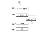
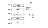
図1は、ETSI NFV-MANOシステムとして配置され得る実施形態のNFV-MANOシステム100のブロック図を例示する。システム100は、オーケストレータ102、仮想ネットワーク機能マネージャ(VNFM)104、および仮想インフラストラクチャ・マネージャ(VIM)106を含む。いくつかの実施形態では、オーケストレータ102は、NFVI上のNFVサービストポロジを実現するとともに、NFVリソースのネットワークワイドのオーケストレーションおよび管理の責任を負う。例えば、オーケストレータ102は、複数のVIMにわたるNFVIリソースおよびネットワークサービスのライフサイクルを管理するように構成され得る。VNFM 104は、VNFインスタンスのライフサイクル管理を提供するように構成され、VIM 106は、ドメイン内のNFVIコンピューティング、記憶装置、およびネットワークリソースを制御および管理するように構成される。
FIG. 1 illustrates a block diagram of an embodiment NFV-
図1に表されたように、オーケストレータ102は、ネットワークサービス要求などのネットワーク要求108を受信する。受信された要求108に従って、オーケストレータ102は、転送グラフ(FG)を決定する。いくつかの実施形態では、転送グラフの決定は、NSカタログ110に従って行われる。その全体が再現されているかのようにここに組み込まれる、2013年10月に発行され、「Network Functions Virtualisation (NFV); Terminology for Main Concepts in NFV」と題する(ETSI)グループ仕様(group specification (GS))NFV 003 v1.1.1に説明されているように、ネットワークサービスは、ネットワーク機能の構成であり、その機能的および挙動的な仕様によって規定される。ETSI NFV-MANOアーキテクチャ・フレームワークによれば、ネットワークサービス要求は、VNF-FGによって記述されることが可能であり、VNF-FGは、ネットワークサービスごとに予め定義される。VNF-FGは、要求されたネットワークサービスに対応する論理トポロジを定義する。ネットワーク機能(NF)転送グラフは、NFノード間のトラフィックフローを記述する目的のための、これらのNFノードを接続する論理リンクのグラフである。VNF-FGは、少なくとも1つのNFノードがVNFノードであるNF転送グラフである。VNF-FGは、サービスプロバイダによって、またはそのシステム・インテグレーション・パートナーによって配置されてもよい。従来のサービスプロバイダネットワークは、典型的に、ネットワークサービスについてのネットワーク要求を受信したときにVNF-FGを生成するために要員(例えば、内容の専門家)に依存している。一実施形態では、サービスプロバイダは、カスタマイズされたネットワークサービスを手動で定義するために典型的なネットワークサービスのテンプレートを使用する。ネットワークサービス(NS)カタログは、ネットワークサービスを対応するVNF-FGにマッピングすることができるネットワークサービスデータベースと見なされ得る。ネットワーク要求108を受信したオーケストレータ102は、ネットワークサービスデータベースから、ネットワーク要求108についての対応するVNF-FGを選択し得る。この開示を通して、「ネットワーク要求」という用語および「ネットワークサービス(NS)要求」という用語は交換可能に使用される。この開示を通して、「NS要求」という用語は、対応するVNF-FGを有するネットワークサービス、またはVNF-FGによって記述されたネットワークサービスを含み得る。この開示を通して、「VNF-FG」および「FG」という用語は交換可能に使用される。「NFVI-PoP」および「PoP」という用語も交換可能に使用される。
As represented in FIG. 1, the
オーケストレータ102は、VNF-FGに含まれるVNFについてNFVI-PoPを決定し、決定されたNFVI-PoPでVNFをインスタンス化し得る。NFVI-PoPは、ネットワーク機能がVNFとして配置されているまたは配置され得るネットワーク存在点である。ここでのVNFのインスタンス化は、NFVI-PoPに対応する1つ以上の物理ネットワークデバイス上でVNFのインスタンスを作成することを指す。
The
ソフトウェア定義トポロジ(software defined topology (SDT))エンティティは、サービスのために仮想ネットワークトポロジまたは仮想データプレーン論理トポロジを確立し得る。SDTエンティティは、ネットワークサービス要求に従って仮想ネットワークトポロジを自律的に作成する。いくつかの実施形態では、SDTエンティティは、FG内のネットワーク機能のインスタンスの数を含むFGを決定し得る。SDTエンティティはまた、FG内の各ネットワーク機能について転送パス(例えば、コントロールプレーンおよびデータプレーンのための)および存在点(PoP)を決定し得る。いくつかの実施形態では、SDTエンティティは、トポロジマネージャ内の機能として実装されてもよく、トポロジマネージャは、顧客要求に基づいてFGを生成し、オーケストレータの機能も実行してもよい。 A software defined topology (SDT) entity may establish a virtual network topology or virtual data plane logical topology for services. The SDT entity autonomously creates a virtual network topology according to the network service request. In some embodiments, the SDT entity may determine an FG that includes the number of network function instances in the FG. The SDT entity may also determine a forwarding path (eg, for the control plane and data plane) and a point of presence (PoP) for each network function in the FG. In some embodiments, the SDT entity may be implemented as a function within the topology manager, which may generate an FG based on the customer request and also perform the function of the orchestrator.
SDTエンティティは、NFVエンティティと組み合わされ得る。一例では、SDTエンティティは、NFV-MANOによってインスタンス化される仮想機能である。SDTエンティティは、NS要求に対応するオーケストレータに論理トポロジを提供し、SDTエンティティとオーケストレータとの間の管理インターフェースを介してオーケストレータと通信し得る。 The SDT entity can be combined with the NFV entity. In one example, the SDT entity is a virtual function instantiated by NFV-MANO. The SDT entity may provide a logical topology to the orchestrator corresponding to the NS request and communicate with the orchestrator via a management interface between the SDT entity and the orchestrator.
SDTエンティティへの入力は、ネットワークサービス要求、トラフィック情報、NFVI情報、およびトリガを含み得る。ネットワークサービス要求は、ノード分布、トラフィック特性などを含み得るサービストラフィック記述を提供する。また、ネットワークサービス要求は、サービス機能チェーンまたはVNF-FGを含み得るサービス機能記述、および機能特性を提供し得る。機能チェーンおよび機能特性の例は、ステートレス機能またはステートフル機能、記憶装置、CPU、およびトラフィックレートにおける機能オーバーヘッド、ならびにPoPの最小数または最大数および優先/非優先PoPなどの機能インスタンス化制約を含む。 Inputs to the SDT entity may include network service requests, traffic information, NFVI information, and triggers. The network service request provides a service traffic description that may include node distribution, traffic characteristics, and the like. The network service request may also provide a service function description and functional characteristics that may include a service function chain or VNF-FG. Examples of functional chains and functional characteristics include functional overhead in stateless or stateful functions, storage, CPU, and traffic rates, and functional instantiation constraints such as minimum or maximum number of PoPs and priority / non-priority PoPs.
トラフィック品質要件は、トラフィックQoS要件およびユーザの体験品質(Quality of Experience (QoE))要件を含み得る。サービス機能品質要件は、有効性および効率性の要件を含み得る。機能有効性は、イベント検出の確率または誤警報の確率を含み得る。機能効率性は、報告応答遅延を含み得る。トラフィック情報は、物理リンク当たり、ノード当たり、および/または論理リンク当たりの統計的な負荷を含んでもよく、例えばデータ解析から得られてもよい。 The traffic quality requirements may include traffic QoS requirements and user quality of experience (QoE) requirements. The service function quality requirements may include the requirements of effectiveness and efficiency. Functional effectiveness may include the probability of event detection or the probability of false alarms. Functional efficiency may include report response delay. The traffic information may include a statistical load per physical link, per node, and / or logical link, and may be obtained from, for example, data analysis.
NFVI情報は、PoPロケーション、PoPごとの機能の利用可能性、およびPoPごとの処理負荷限度を含み得る。一実施形態では、NFVI情報は、物理リンク容量および無線リソースなどの残りの公称ネットワークリソースとともに、デバイス、基地局(BS)、ルータ、およびNFVI-PoPの間の統計的な負荷、遅延、容量を含み得る。トリガイベントは、ネットワークサービスの変化を開始し得る。一実施形態では、トリガイベントは、タイムアウト期間の後または性能条件が満たされたとき、例えば、サービス、SDT、および/またはトラフィックエンジニアリング(TE)性能メトリックが閾値を下回ったときまたは上回ったとき)に発生する。別の実施形態では、トリガイベントは、人間の行為によって誘発され、例えば、サービスプロバイダが、手動でトリガイベントを誘発させる。 The NFVI information may include PoP location, availability of features per PoP, and processing load limits per PoP. In one embodiment, the NFVI information includes the statistical load, delay, capacity between the device, base station (BS), router, and NFVI-PoP along with the remaining nominal network resources such as physical link capacity and radio resources. May be included. A triggering event may initiate a change in network service. In one embodiment, the trigger event is after a timeout period or when a performance condition is met (eg, when a service, SDT, and / or traffic engineering (TE) performance metric falls below or exceeds a threshold). Occur. In another embodiment, the triggering event is triggered by human action, eg, the service provider manually triggers the triggering event.
図2は、NFV-MANOを実行するための実施形態のシステム200のブロック図を例示する。システム200は、トポロジマネージャ202、VNFM 204、およびVIM 206を含む。トポロジマネージャ202は、顧客要求208に基づいてFGを生成するとともに、オーケストレータの機能を実行するように構成されたソフトウェアモジュールまたはエンティティであり得る。いくつかの実施形態では、トポロジマネージャ202は、入ってくる顧客要求をVNF-FGに変換してもよく、これは、本質的に、論理リンク(またはエッジ)によって相互接続される、サービス特有のVNF(または頂点)を含む論理トポロジ(またはグラフ)である。トポロジマネージャ202は、FGを生成するためにSDT技術を使用し得る。VNFカタログ210は、インスタンス化されることが可能である様々なVNFのデータベースを備えてもよく、FG内のVNFのインスタンス化においてトポロジマネージャ202によってアクセスされてもよい。
FIG. 2 illustrates a block diagram of an
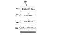
図3は、図2のシステム200において使用され得るNFV-MANOの実施形態の方法300のフローチャートを例示する。表されたように、トポロジマネージャは、顧客から、ネットワークサービスについての顧客要求を受信する(ステップ302)。顧客要求の受信に応答して、トポロジマネージャは、顧客要求に従ってVNF-FGを生成または決定する(ステップ304)。顧客要求は、VNF-FGを構築するために使用される、基本ネットワーク構成要素またはサービス要求のチェックリストを含み得る。例えば、顧客は、(例えば、テンプレートのリストから)ロング・ターム・エボリューション(Long Term Evolution (LTE))ネットワークおよび追加のサービス特有のネットワーク機能を要求することができる。トポロジマネージャは、チェックリストの使用によってネットワークサービスを構築し、例えばネットワーク・サービス・カタログを使用して、構築されたネットワークサービスに従ってVNF-FGを生成し得る。一実施形態では、VNF-FGは、サービス特有ではないが、ネットワーク性能の評価および強化に関連する追加のVNFを含んでもよく、例えば、VNF-FGは、トラフィック解析またはQoEモニタのためのVNFを含んでもよい。これらの追加のVNFも、VNFカタログからアクセス可能であり得る。
FIG. 3 illustrates a flowchart of a
そして、トポロジマネージャは、VNF-FG内のVNFのそれぞれについてNFVI-PoPを決定し得る(ステップ306)。NFVI-PoPは、ネットワーク機能がVNFとして配置されているまたは配置され得るネットワーク存在点である。例えば、トポロジマネージャは、転送グラフが埋め込まれ得る物理ネットワーク内のVNF-FG内のVNFに対応するNFVI-PoPを特定し得る。一実施形態では、VNFに関連付けられるNFVI-PoPは、例えば、VIMを介してアクセス可能なNFVI情報を使用して、VNFをサポートすることができる複数の利用可能なNFVI-PoPの実行可能性をチェックし、複数の利用可能なNFVI-PoPから実行可能なNFVI-PoPを選択することによって決定され得る。NFVI-PoPが決定され、そしてトポロジマネージャは、1つ以上のVNFMおよびVIMを使用して、決定されたNFVI-PoPでVNFをインスタンス化することができる(ステップ308)。一実施形態では、NFVI-PoPが決定された後、トポロジマネージャは、1つ以上のVNFMおよびVIMに、対応するVNFをインスタンス化するよう命令し得る。一実施形態では、VIMは、VNFのそれぞれについてコンテナ、例えば、ネットワークノードにおけるコンピューティングリソースを予約してもよく、VNFMは、コンテナでVNFをインスタンス化してもよい。いくつかの実施形態では、トポロジマネージャは、VNF-FGおよびNFVI-PoPを、順次的ではなく一緒に決定し得る。 The topology manager may then determine NFVI-PoP for each of the VNFs in the VNF-FG (step 306). NFVI-PoP is a network presence point where network functions are or can be deployed as VNFs. For example, the topology manager may identify NFVI-PoPs that correspond to VNFs in VNF-FGs in the physical network in which the forwarding graph may be embedded. In one embodiment, an NFVI-PoP associated with a VNF can use multiple NFVI-PoP feasibility that can support VNF using, for example, NFVI information accessible via VIM. It can be determined by checking and selecting a viable NFVI-PoP from the plurality of available NFVI-PoPs. The NFVI-PoP is determined, and the topology manager can instantiate VNF with the determined NFVI-PoP using one or more of the VNFM and VIM (step 308). In one embodiment, after the NFVI-PoP is determined, the topology manager may instruct one or more VNFMs and VIMs to instantiate the corresponding VNF. In one embodiment, the VIM may reserve a computing resource in a container, eg, a network node, for each VNF, and the VNFM may instantiate the VNF in the container. In some embodiments, the topology manager may determine VNF-FG and NFVI-PoP together rather than sequentially.
イベント/命令(例えば、VNFスケール・イン/アウト)は、トポロジマネージャがVNFを新しいPoPに移動することを命令または要求するように、VIMまたはVNFMを促し得る。トポロジマネージャは、ステップ306〜308と同様の一連のステップを実行することによってVNFを新しいPoPに移動し得る。 An event / command (eg, VNF scale in / out) may prompt the VIM or VNFM to instruct or require the topology manager to move the VNF to the new PoP. The topology manager may move the VNF to a new PoP by performing a series of steps similar to steps 306-308.
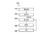
図4は、NFV-MANOを実行するための別の実施形態のシステム400のブロック図を例示する。システム400は、SDT-FGエンティティ402、SDT-PoPエンティティ404、VNFM 406、およびVIM 408を含む。いくつかの実施形態では、SDT-FGエンティティ402およびSDT-PoPエンティティ404は、それぞれ、顧客要求410に基づいて転送グラフを生成する、および転送グラフ内のVNFに対するPoPを決定するためのソフトウェアモジュールまたはエンティティである。一実施形態では、SDT-FGエンティティ402は、顧客要求410に基づいて転送グラフを生成するSDT技術を使用し得る。また、SDT-PoPエンティティ404は、1つ以上のVNFM 406および1つ以上のVIM 408を使用して転送グラフ内のVNFのインスタンス化を命令するように構成され得る。いくつかの実施形態では、顧客要求410に対応するサービス要求は、SDT-FGエンティティ402によって、VNFおよび論理リンクを含む転送グラフに変換され得る。そして、結果として得られた転送グラフは、NS要求としてSDT-PoPエンティティ404に提供され得る。NFVIにおけるリソースの利用可能性に基づいて、VNFに対応するPoPは、VNFM 406およびVIM 408に、対応するPoPにおいてVNFをインスタンス化させるための命令を生成し得るSDT-PoPエンティティ404によって決定され得る。
FIG. 4 illustrates a block diagram of another
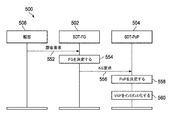
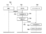
図5は、図4のシステム400で使用され得るNFV-MANOの実施形態の方法500のメッセージフロー図を例示する。SDT-FGエンティティ502は、顧客506から、ネットワークサービスについての顧客要求を受信し(ステップ552)、顧客要求に従ってVNF-FGを生成または決定する(ステップ554)。一実施形態では、SDT-FGエンティティ502は、新しいネットワークサービスを構築し、新しいネットワークサービスおよびネットワーク・サービス・カタログを使用してVNF-FGを生成するために、顧客要求において提供される基本ネットワークサービスを使用し、または組み合わせ得る。SDT-FGエンティティ502は、ネットワークサービス(NS)要求を構築し、SDT-PoPエンティティ504に送信し得る(ステップ556)。NS要求は、生成されたVNF-FG、およびVNF-FGに対応するネットワークサービスを含み得る。NS要求は、SDT-FGエンティティ502によって構成され得る。SDT-PoPエンティティ504は、NS要求を受信すると、VNF-FGに示されているVNFに対するNFVI-PoPを決定し(ステップ558)、1つ以上のVNFMおよびVIMを使用してVNFをインスタンス化し得る(ステップ560)。
FIG. 5 illustrates a message flow diagram of a
図5に表された実施形態では、FGおよびNFVI-PoPは、それぞれSDT-FGエンティティ502およびSDT-PoPエンティティ504によって順次的に決定される。さらに、FGおよびNFVI-PoPは、異なるエンティティによって決定され、提供されるが、これは、SDT-FGエンティティ502およびSDT-PoPエンティティ504が異なるベンダーによってサポートされ、維持管理され得るので有益であり得る。SDT-FGエンティティ502およびSDT-PoPエンティティ504のそれぞれは、互いと通信し得るように定義されたインターフェースを有し得る。VNFスケール・イン/アウト・トリガがVNFM 406またはVIM 408などのVNFMまたはVIMに送信される場合、このトリガのトリガメッセージは、SDT-PoPエンティティ504に転送されてもよく、SDT-PoPエンティティ504は、新しいNFVI-PoPを決定し、新しいPoPでVNFをインスタンス化するステップ558および560を繰り返してもよい。
In the embodiment depicted in FIG. 5, FG and NFVI-PoP are determined sequentially by SDT-
図6は、NFV-MANOを実行するための別の実施形態のシステム600のブロック図を例示する。この例では、システム600は、SDT-FGエンティティ602、オーケストレータ604、VNFM 606、およびVIM 608を含む。SDT-FGエンティティ602は、顧客要求610に基づいてFGを生成するように構成される。この生成されたFGは、生成されたFGおよび顧客要求610に含まれるネットワークサービス情報を用いてNSカタログ614を更新するために使用されることが可能である。例えば、顧客要求610を受信すると、SDT-FGエンティティ602は、顧客要求のサービス要件をFGに変換し得る。FGは、オーケストレータ604に提供される。オーケストレータ604は、FG内のVNFに対するPoPを決定し、対応するPoPで、1つ以上のVNFM 606および1つ以上のVIM 608を使用した、VNFのインスタンス化を命令するように構成される。一実施形態では、SDT-FGエンティティ602は、生成されたFGを使用してNS要求を構築し、VNFのPoPの決定およびインスタンス化のためにオーケストレータ604にNS要求を送信し得る。この例では、システム600は、図1に表されたようなNFV-MANOシステム100に基づいて構築されてもよく、SDT-FGエンティティ602の出力、すなわちNS要求は、NFV-MANOシステム100の入力として使用される。
FIG. 6 illustrates a block diagram of another embodiment of a
図7は、図6のシステム600において使用され得るNFV-MANOの実施形態の方法のシーケンス図700を例示する。SDT-FGエンティティ702は、顧客712から、ネットワークサービスについての顧客要求を受信する(ステップ752)。顧客要求の受信752に応答して、SDT-FG702は、顧客要求に対応するFGを決定し、または生成する(ステップ754)。一実施形態では、SDT-FGエンティティ702は、ネットワーク・サービス・テンプレート、および基本ネットワーク機能を含むチェックリストを使用してFGを生成し得る。そして、SDT-FGエンティティ702は、顧客要求情報および生成されたFGを含むNS要求を構築し、このNS要求をNSリポジトリまたはカタログに追加する(ステップ756)。一実施形態では、ネットワークサービスおよび対応するFGを含むNS要求が構築されてもよく、NSカタログにアーカイブされた後に再利用されてもよい。例えば、FGは、同様のネットワークサービスについての顧客要求が受信されたときに再利用され得る。
FIG. 7 illustrates a sequence diagram 700 of a method of an NFV-MANO embodiment that may be used in the
SDT-FGエンティティ702は、NS要求をオーケストレータ704に送信する(ステップ762)。NS要求を受信すると、オーケストレータ704は、図1に例示された方法を含む複数の異なる方法のいずれかを使用して、要求について動作する。例えば、NS要求に基づいて、オーケストレータ704は、FGに示されているVNFに対するNFVI-PoPを決定し(ステップ764)、VNFM 606およびVIM 608などの1つ以上のVNFMおよびVIMにVNFをインスタンス化するように命令し得る(ステップ766)ことができる。この技術分野の当業者は、ステップ762においてNS要求を送信することは、ステップ756においてNSリポジトリを修正することを待つ必要がないことを理解するであろう。これらのステップは、表された順序と逆の順序で起こることが可能であり、または同時に起こることが可能である。
The SDT-
いくつかの実施形態では、VNFスケール・イン/アウト・トリガがVNFMまたはVIMのいずれかに送信される場合、トリガメッセージは、オーケストレータ704に転送されてもよく、オーケストレータ704は、図7に例示されたようなステップ764および766を繰り返してもよい。代わりに、VNFMまたはVIMは、スケール・イン/アウトの必要性の表示を受信し、トリガを直接処理し得る。
In some embodiments, if the VNF scale in / out trigger is sent to either VNFM or VIM, the trigger message may be forwarded to the
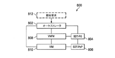
図8は、NFV-MANOを実行するための別の実施形態のシステム800を例示する。システム800は、オーケストレータ802、SDT-FGエンティティ804、SDT-PoPエンティティ806、VNFM 808、およびVIM 810を含む。SDT-FGエンティティ804は、顧客要求812に基づいてFGを生成する。顧客要求812は、オーケストレータ802によって受信され、そしてSDT-FGエンティティ804に転送されることが可能である。SDT-FG 804は、オーケストレータ802から受信された顧客要求812に関連する情報に従ってFGを生成する。SDT-PoPエンティティ806は、FG内のVNFに対するPoPを決定する。オーケストレータ802は、1つ以上のVNFM 808および1つ以上のVIM 810を使用して、PoPでのFG内のVNFのインスタンス化を命令するように構成される。
FIG. 8 illustrates another
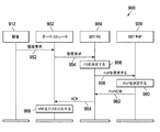
図9は、図8に例示されたようなシステム800において使用され得るNFV-MANOの実施形態の方法900のシーケンス図を例示する。オーケストレータ902は、顧客912から、ネットワークサービスについての顧客要求を受信する(ステップ952)。顧客要求、または顧客要求に従って決定された情報は、SDT-FGエンティティ904に送信される(ステップ954)。SDT-FGエンティティ904は、受信された情報に従ってFGを生成する(ステップ956)。決定されたFGに基づいて、FGをインスタンス化するために要求されるPoPの決定についての要求が、SDT-PoPエンティティ906に送信される(ステップ958)。そしてSDT-PoPエンティティ906は、受信された要求に従ってVNFに対するPoPを決定し(ステップ960)、要求PoPコマンドに応答して、PoPの決定が完了したことを示す、PoP応答メッセージなどのメッセージをSDT-FGエンティティ904に送信する(ステップ962)。この技術分野の当業者は、ステップ958で送信される、PoPについての要求は、決定されたFGを含み得ることを理解するであろう。同様に、ステップ962のPoP応答メッセージは、FG内の各VNFについての選択されたPoPのリストを含み得る。SDT-FGエンティティ904は、PoP応答メッセージを受信したとき、FGの生成およびFG内のVNFに対するNFVI-PoPの決定を示す確認(ACK)メッセージをオーケストレータ902に送信し得る(ステップ964)。ACKメッセージを受信すると、オーケストレータ902は、1つ以上のVNFMおよびVIMを使用した、NFVI-PoPに基づく、FGに含まれるVNFのインスタンス化を命令することができる(ステップ966)。
FIG. 9 illustrates a sequence diagram of a
いくつかの実施形態では、オーケストレータ902は、SDT-FGエンティティ904からのACKメッセージの受信に応答して、VNFをインスタンス化するための命令を発行し得る。インスタンス化するための命令は、VNFのPoP、例えばステップ960でSDT-PoP 906により特定されたPoPに関連するVNFMおよびVIMに送信され得る。代わりに、VNFをインスタンス化するための命令は、また、PoPが決定された後にSDT-PoPエンティティ906から直接出され得る。例えば、SDT-PoPエンティティ906は、PoPが決定された後にインスタンス化コマンドをVNFMに送信し得る。1つ以上のVNFが新しいPoPに移動され、または新しいPoPでインスタンス化されることを要求するVNFスケール・イン/アウト・トリガがVNFMまたはVIMのいずれかに送信される場合、トリガメッセージは、SDT-PoPエンティティ906に転送されてもよく、そしてステップ960〜966が繰り返されてもよい。例えば、トリガメッセージを受信すると、SDT-PoPエンティティ906は、要求された新しいPoPを決定し、PoP応答をSDT-FGエンティティ904に送信する。そしてSDT-FGエンティティ904は、確認メッセージをオーケストレータ902に送信し、オーケストレータ902は、新しいPoPでVNFをインスタンス化するための命令を送信する。
In some embodiments, the
いくつかの実施形態では、本開示の実施形態におけるオーケストレータ、SDT-FGエンティティ、およびSDT-PoPエンティティは、同じサービスプロバイダまたは異なるサービスプロバイダによって実装され得る。他の実施形態では、オーケストレータ、SDT-FGエンティティ、およびSDT-PoPエンティティは、互いとやり取りするためのインターフェースを有する異なるエンティティとして実装され得る。これらのエンティティは、ソフトウェアによって動作可能にされてもよく、仮想化されたエンティティであってもよい。 In some embodiments, the orchestrator, SDT-FG entity, and SDT-PoP entity in embodiments of the present disclosure may be implemented by the same service provider or by different service providers. In other embodiments, the orchestrator, SDT-FG entity, and SDT-PoP entity may be implemented as different entities with interfaces for interacting with each other. These entities may be enabled by software or may be virtualized entities.
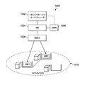
図10は、単一のデータセンタ(DC)でVNFがインスタンス化された実施形態のNFV-MANOシステム1000の図を例示する。トポロジマネージャまたはオーケストレータ1002は、VIM 1004を通して全体のネットワークについてのリソースの利用可能性のビューを有する。トポロジマネージャ1002は、顧客要求に基づいてVNFのVNF-FG、すなわち論理トポロジを決定し、VNF-FG内のVNFに対するPoP、すなわちVNFに対する物理トポロジを決定する。この例では、VNF-FGは、一緒にリンクされた2つのVNF、すなわちVNF1およびVNF2を含み、2つのVNFは、同じNFVI-PoP 1010(この例では、NFVI-PoP 1010は単一のデータセンタである)に共同配置されている。VIM 1004は、2つのVNFに対する仮想化コンテナおよび物理リンクなどのリソースを割り当て、予約する。オーケストレータ1002から受信された命令について動作するVNFM 1006は、VNFをインスタンス化する。NFVI-PoP 1010、すなわちデータセンタにおいて、ソフトウェア定義ネットワークコントローラ(software defined network controller (SDN-C))1008は、そのNFVI-PoP内の物理リンクを決定し、インスタンス化されるVNFを含むデータプレーンのための転送ルールを提供する。
FIG. 10 illustrates a diagram of an embodiment NFV-
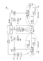
図11は、複数のDCにわたりVNFがインスタンス化された別の実施形態NFV-MANOシステム1100の図を例示する。システム1100は、システム1100内のVNFリソースのオーケストレーションおよび管理の責任を負うトポロジマネージャ1102と、複数のVIM 1104であって、それぞれがそれぞれのドメイン内のリソースを予約し、割り当てるように構成された複数のVIM 1104と、複数のVNFM 1106であって、それぞれがそれぞれのドメイン内のVNFをインスタンス化するように構成された複数のVNFM 1106とを含む。また、システム1100は、複数のSDN-C 1108であって、それぞれがVIM 1104のドメイン内にある複数のSDN-C 1108を含む。SDN-C 1108のそれぞれは、対応する物理リンクを決定し、そのNFVI-PoP内の転送ルールを提供する。システム1100は、複数の広域ネットワーク・インフラストラクチャ・マネージャ(WIM)1110をさらに含み、これらのそれぞれは、特殊なVIMであり、NFVI-PoP 1122および1124間のリソースの抽象化ビューをトポロジマネージャ1102に提供する。WIM 1110の管理ドメイン内のSDN-C 1112は、物理リンクを決定し、NFVI-PoP 1122および1124間の転送ルールを提供する。VIM 1104またはWIM 1110のそれぞれは、その管理ドメイン内の接続サービスを提供し、リソースの抽象化をトポロジマネージャ1102に提供する。VIM 1104またはWIM 1110のそれぞれは、また、そのドメイン内のNFVIリソースリポジトリを維持管理する。図11に表されたように広域ネットワークを通過するエンドポイント(end point (EP))1114からEP 1116への、ネットワークサービスに対応する顧客要求について、転送グラフは、NFVI-PoP 1122およびNFVI-PoP 1124にそれぞれ対応する2つのVNF、すなわちVNF1およびVNF2を含むように決定され得る。VNF1は、VNFM 1106によってNFVI-PoP 1122でインスタンス化されてもよく、VNF2は、別のVNFM 1106によってNFVI-PoP 1124でインスタンス化されてもよい。トポロジマネージャ1102がEP 1114をNFVI-PoP1 1122内のVNF1と接続するために使用されるリソースへの可視性(およびその制御)を有するように、第2のWIM 1110およびSDN-C 1112がトポロジマネージャ1102に利用可能であり得ることがこの技術分野の当業者によって理解されるであろう。これは、NFVI-PoP1 1122とNFVI-PoP2 1124との間で動作するWIM 1110とほとんど同じように動作する。別々のエンティティとして表されているが、2つのWIM 1110は、データセンタの外部に1組のみのWIMおよび対応するSDN-Cが存在するように2つのSDN-C 1112と共に組み合わされ得る。WIMおよび対応するSDN-Cの数は、動作上の決定である。
FIG. 11 illustrates a diagram of another embodiment NFV-
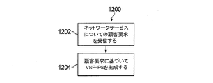
図12は、処理システムによって実行され得るNFV-MANOのための実施形態の方法1200のフローチャートを例示する。方法1200では、ステップ1202において、ネットワークサービスについての顧客要求が受信される。ステップ1204において、受信された顧客要求に従って、VNF-FGが生成される。VNF-FGは、複数のVNFを含むことができる。一実施形態では、VNF-FGは、ネットワーク性能の評価および強化に関連するVNFを含み得る。一実施形態では、方法1200はさらに、VNF-FG内の複数のVNFのそれぞれについてNFVI-PoPを決定し、NFVI-PoPでVIMおよびVNFMを使用して複数のVNFをインスタンス化し得る。別の実施形態では、方法1200は、生成されたVNF-FGを含むNS要求を構築し、このNS要求を送信してもよく、このNS要求に基づいて、複数のVNFに対するNFVI-PoPが決定されてもよい。構築されたNS要求は、NSカタログに追加され得る。別の実施形態では、方法1200は、複数のVNFに対するNFVI-PoPの決定について要求するコマンドを送信し、VNF-FG内の複数のVNFに対するNFVI-PoPの決定を示すコマンドに応答してメッセージを受信し得る。さらに別の実施形態では、方法1200はまた、顧客要求に応答して、VNF-FGの生成およびVNF-FG内の複数のVNFに対するNFVI-PoPの決定を示す確認メッセージを送信し得る。
FIG. 12 illustrates a flowchart of an
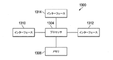
図13は、ホストデバイスに設置され得る、ここに説明されるシステムおよび方法を実装するための実施形態の処理システム1300のブロック図を例示する。処理システム1300は、本開示の実施形態におけるオーケストレータ、SDT-FGエンティティ、およびSDT-PoPエンティティのうちのいずれか1つ以上の機能を実行するために使用され得る。表されたように、処理システム1300は、プロセッサ1304、メモリ1306、およびインターフェース1310〜1314を含み、これらは、図13に表されたように配置されてもよい(または配置されなくてもよい)。プロセッサ1304は、計算および/または他の処理関連タスクを実行するように適合されたいずれかの構成要素または構成要素の集合であってよく、メモリ1306は、プロセッサ1304による実行のためのプログラミングおよび/または命令を記憶するように適合されたいずれかの構成要素または構成要素の集合であってもよい。一実施形態では、メモリ1306は、非一時的なコンピュータ読み取り可能な媒体を含む。インターフェース1310、1312、1314は、処理システム1300が他のデバイス/構成要素および/またはユーザと通信することを可能にするいずれかの構成要素または複数の構成要素の集合であってもよい。例えば、インターフェース1310、1312、1314のうちの1つ以上は、プロセッサ1304からのデータ、制御、または管理のメッセージを、ホストデバイスおよび/またはリモートデバイスにインストールされたアプリケーションに伝達するように適合され得る。別の例として、インターフェース1310、1312、1314のうちの1つ以上は、ユーザまたはユーザデバイス(例えば、パーソナルコンピュータ(PC)など)が処理システム1300とやり取り/通信することを可能にするように適合され得る。処理システム1300は、長期記憶(例えば、不揮発性メモリなど)のような、図13には描かれていない追加の構成要素を含み得る。
FIG. 13 illustrates a block diagram of an
いくつかの実施形態では、処理システム1300は、電気通信ネットワークにアクセスする、またはそうでなければ電気通信ネットワークの一部であるネットワークデバイスに含まれる。一例では、処理システム1300は、無線または有線電気通信ネットワーク内の、基地局、中継局、スケジューラ、コントローラ、ゲートウェイ、ルータ、アプリケーションサーバ、または電気通信ネットワーク内のいずれかの他のデバイスなどのネットワーク側デバイス内にある。他の実施形態では、処理システム1300は、無線または有線電気通信ネットワークにアクセスする、移動局、ユーザ機器(UE)、パーソナルコンピュータ(PC)、タブレット、ウェアラブル通信デバイス(例えば、スマートウォッチなど)、または電気通信ネットワークにアクセスするように適合されたいずれかの他のデバイスなどのユーザ側デバイス内にある。
In some embodiments, the
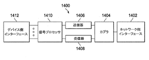
いくつかの実施形態では、インターフェース1310、1312、1314のうちの1つ以上は、処理システム1300を、電気通信ネットワーク上でシグナリングを送信し、受信するように適合されたトランシーバに接続する。図14は、電気通信ネットワーク上でシグナリングを送信し、受信するように適合されたトランシーバ1400のブロック図を例示する。トランシーバ1400は、ホストデバイスに設置され得る。表されたように、トランシーバ1400は、ネットワーク側インターフェース1402、カプラ1404、送信器1406、受信器1408、信号プロセッサ1410、および1つ以上のデバイス側インターフェース1412を含む。ネットワーク側インターフェース1402は、無線または有線電気通信ネットワーク上でシグナリングを送信し、受信するように適合されたいずれかの構成要素または構成要素の集合を含み得る。カプラ1404は、ネットワーク側インターフェース1402上で双方向通信を容易にするように適合されたいずれかの構成要素または構成要素の集合を含み得る。送信器1406は、ベースバンド信号を、ネットワーク側インターフェース1402上での送信に適した変調された搬送波信号に変換するように適合されたいずれかの構成要素または構成要素の集合(例えば、アップコンバータ、電力増幅器など)を含み得る。受信器1408は、ネットワーク側インターフェース1402上で受信された搬送波信号をベースバンド信号に変換するように適合されたいずれかの構成要素または構成要素の集合(例えば、ダウンコンバータ、低雑音増幅器など)を含み得る。信号プロセッサ1410は、ベースバンド信号を、デバイス側インターフェース1412上の通信に適したデータ信号に、またはその逆に変換するように適合されたいずれかの構成要素または構成要素の集合を含み得る。デバイス側インターフェース1412は、信号プロセッサ1410とホストデバイス内の構成要素(例えば、処理システム1300、ローカル・エリア・ネットワーク(LAN)ポートなど)との間でデータ信号を伝達するように適合されたいずれかの構成要素または構成要素の集合を含み得る。
In some embodiments, one or more of the
トランシーバ1400は、いずれかの種類の通信媒体上で信号を送信し、受信し得る。いくつかの実施形態では、トランシーバ1400は、無線媒体上で信号を送信し、受信する。例えば、トランシーバ1400は、セルラプロトコル(例えば、LTEなど)、無線ローカル・エリア・ネットワーク(WLAN)プロトコル(例えば、Wi-Fiなど)、またはいずれかの他の種類の無線プロトコル(例えば、ブルートゥース(登録商標)、近距離通信(NFC)など)のような無線電気通信プロトコルに従って通信するように適合された無線トランシーバであり得る。そのような実施形態では、ネットワーク側インターフェース1402は、1つ以上のアンテナ/放射素子を備える。例えば、ネットワーク側インターフェース1402は、単一のアンテナ、複数の別々のアンテナ、またはマルチレイヤ通信のために構成されたマルチアンテナアレイ、例えば、単入力多出力(single input multiple output (SIMO))、多入力単出力(multiple input single output (MISO))、多入力多出力(multiple input multiple output (MIMO))などを含み得る。他の実施形態では、トランシーバ1400は、有線媒体、例えば、ツイストペアケーブル、同軸ケーブル、光ファイバなどの上でシグナリングを送信し、受信する。特定の処理システムおよび/またはトランシーバは、表された構成要素のすべてを利用してもよく、または構成要素のサブセットのみを利用してもよく、統合レベルは、デバイスごとに変わり得る。
The
説明が詳細に記載されたが、添付の請求項によって規定されるような、この開示の思想および範囲から逸脱することなく、様々な変更、置換、および修正が行われることが可能であることが理解されるべきである。さらに、現在存在し、または後に開発されるプロセス、機械、製造品、物の組成、手段、方法、またはステップが、ここに説明された対応する実施形態と実質的に同じ機能を実行し、または実質的に同じ結果を達成し得ることを、この技術分野の当業者はこの開示から容易に理解するので、開示の範囲は、ここに説明された特定の実施形態に限定されることは意図されない。したがって、添付の請求項は、そのようなプロセス、機械、製造品、物の組成、手段、方法、またはステップをその範囲内に含むことが意図される。 Although the description has been set forth in detail, various changes, substitutions, and modifications can be made without departing from the spirit and scope of this disclosure as defined by the appended claims. Should be understood. In addition, a process, machine, article of manufacture, product composition, means, method, or step that currently exists or is later developed performs substantially the same function as the corresponding embodiment described herein, or As those skilled in the art will readily appreciate from this disclosure that substantially the same results can be achieved, the scope of the disclosure is not intended to be limited to the specific embodiments described herein. . Accordingly, the appended claims are intended to include within their scope such processes, machines, manufacture, compositions of matter, means, methods, or steps.
100、200、400、600、800、1000、1100 システム
102、604、802、902 オーケストレータ
104、204、406、606、808、1006、1106 仮想ネットワーク機能マネージャ
106、206、408、608、810、1004、1104 仮想インフラストラクチャ・マネージャ
108 ネットワーク要求
110、614 NSカタログ
202、1002、1102 トポロジマネージャ
208、410、610、812 顧客要求
210 VNFカタログ
300、500、900、1200 方法
302、304、306、308、552、554、556、558、560、752、754、756、762、764、766、952、954、956、958、960、962、964、966、1202、1204 ステップ
402、502、602、702、804、904 SDT-FGエンティティ
404、504、704、806、906 SDT-PoPエンティティ
506、712、912 顧客
700 シーケンス図
1008、1108、1112 ソフトウェア定義ネットワークコントローラ
1010 NFVI-PoP
1110 広域ネットワーク・インフラストラクチャ・マネージャ
1114 エンドポイント1
1116 エンドポイント2
1122 NFVI-PoP1
1124 NFVI-PoP2
1300 処理システム
1304 プロセッサ
1306 メモリ
1310、1312、1314 インターフェース
1400 トランシーバ
1402 ネットワーク側インターフェース
1404 カプラ
1406 送信器
1408 受信器
1410 信号プロセッサ
1412 デバイス側インターフェース
100, 200, 400, 600, 800, 1000, 1100 systems
102, 604, 802, 902 Orchestrator
104, 204, 406, 606, 808, 1006, 1106 Virtual Network Function Manager
106, 206, 408, 608, 810, 1004, 1104 Virtual Infrastructure Manager
108 Network Request
110, 614 NS Catalog
202, 1002, 1102 Topology Manager
208, 410, 610, 812 customer requirements
210 VNF Catalog
300, 500, 900, 1200 methods
302, 304, 306, 308, 552, 554, 556, 558, 560, 752, 754, 756, 762, 764, 766, 952, 954, 958, 960, 962, 964, 962, 1202, 1204 steps
402, 502, 602, 702, 804, 904 SDT-FG entities
404, 504, 704, 806, 906 SDT-PoP entities
506, 712, 912 customers
700 sequence diagram
1008, 1108, 1112 software defined network controller
1010 NFVI-PoP
1110 Wide Area Network Infrastructure Manager
1114
1116
1122 NFVI-PoP1
1124 NFVI-PoP2
1300 processing system
1304 processor
1306 Memory
1310, 1312, 1314 interface
1400 transceiver
1402 Network Side Interface
1404 coupler
1406 transmitter
1408 receiver
1410 signal processor
1412 Device side interface
Claims (18)
処理システムによって、ネットワークサービスについての顧客要求を受信するステップであって、前記顧客要求は、ネットワーク構成要素またはネットワークサービス要求のチェックリストを含む、ステップと、
前記処理システムによって、前記顧客要求に含まれるチェックリストを使用してネットワークサービス(NS)を構築するステップと、
ネットワークサービス(NS)カタログを使用して、前記構築されたNSに従って、複数の仮想化ネットワーク機能(VNF)および前記複数のVNFのうちの2つを接続するリンクを含む仮想化ネットワーク機能転送グラフ(VNF-FG)を生成するステップと
を含む方法。 A method for network function virtualization management and orchestration (NFV-MANO),
Receiving by the processing system a customer request for network services, the customer request including a checklist of network components or network service requests ;
Establishing a network service (NS) by the processing system using a checklist included in the customer request;
A virtualized network function forwarding graph comprising a plurality of virtualized network functions (VNF) and a link connecting two of the plurality of VNFs according to the constructed NS using a network service (NS) catalog ( Generating a VNF-FG).
をさらに含む、請求項1に記載の方法。 The method of claim 1, further comprising: determining an NFV infrastructure presence point (NFVI-PoP) for each of the plurality of VNFs in the VNF-FG.
をさらに含む、請求項1または2に記載の方法。 By the processing system, further comprising the step of sending instructions for instantiating the plurality of VNF using virtual infrastructure manager (VIM) and virtual network feature manager (VNFM), in claim 1 or 2 Method described.
前記処理システムによって、前記VNF-FG内の前記複数のVNFのそれぞれに対するNFVI-PoPを決定するために、前記ネットワークサービス要求を送信するステップと
をさらに含む、請求項1に記載の方法。 Establishing by the processing system a network service (NS) request including the generated VNF-FG and the constructed network service ;
By the processing system, in order to determine the NFVI-PoP for each of the plurality of VNF in the VNF-FG, further comprising the step of transmitting said network service request method according to claim 1.
をさらに含む、請求項1に記載の方法。 The method according to claim 1, further comprising: transmitting, by the processing system, a command requesting determination of NFVI-PoP for the plurality of VNFs in the VNF-FG.
をさらに含む、請求項6に記載の方法。 7. The method of claim 6 , further comprising receiving a message indicating the determination of the NFVI-PoP for the plurality of VNFs in the VNF-FG in response to the command.
をさらに含む、請求項7に記載の方法。 The method of claim 7 , further comprising: sending a confirmation message in response to the customer request indicating creation of the VNF-FG and determination of NFVI-PoP for the plurality of VNFs in the VNF-FG. .
プロセッサと、
前記プロセッサによる実行のためのプログラミングを記憶する非一時的なコンピュータ読み取り可能な記憶媒体とを含み、前記プログラミングが、
ネットワークサービスについての顧客要求を受信するための命令であって、前記顧客要求は、ネットワーク構成要素またはネットワークサービス要求のチェックリストを含む、命令と、
前記顧客要求に含まれるチェックリストを使用してネットワークサービス(NS)を構築するための命令と、
ネットワークサービス(NS)カタログを使用して、前記構築されたNSに従って、複数の仮想化ネットワーク機能(VNF)および前記複数のVNFのうちの2つを接続するリンクを含む仮想化ネットワーク機能転送グラフ(VNF-FG)を生成するための命令と
を含む、装置。 A device,
A processor,
A non-transitory computer readable storage medium storing programming for execution by said processor, said programming comprising
Instructions for receiving a customer request for a network service, the customer request including a checklist of network components or network service requests ;
Instructions for establishing a network service (NS) using the checklist included in the customer request;
A virtualized network function forwarding graph comprising a plurality of virtualized network functions (VNF) and a link connecting two of the plurality of VNFs according to the constructed NS using a network service (NS) catalog ( Instruction to generate VNF-FG)
Devices , including:
前記VNF-FG内の前記複数のVNFのそれぞれについてNFVインフラストラクチャ存在点(NFVI-PoP)を決定する
ためのさらなる命令を含む、請求項10に記載の装置。 The programming is
Wherein for each of said plurality of VNF in VNF-FG containing further instructions for determining NFV infrastructure exists point (NFVI-PoP), according to claim 1 0.
仮想インフラストラクチャ・マネージャ(VIM)および仮想ネットワーク機能マネージャ(VNFM)を使用して前記複数のVNFをインスタンス化するための命令を送信する
ためのさらなる命令を含む、請求項10または11に記載の装置。 The programming is
Including further instructions to send instructions for instantiating the plurality of VNF using virtual infrastructure manager (VIM) and virtual network feature manager (VNFM), according to claim 1 0 or 11 apparatus.
前記生成されたVNF-FGおよび前記構築されたネットワークサービスを含むネットワークサービス(NS)要求を構築し、
前記VNF-FG内の前記複数のVNFのそれぞれに対するNFVI-PoPの決定のために、前記構築されたNS要求を送信する
ためのさらなる命令を含む、請求項10に記載の装置。 The programming is
Construct a network service (NS) request including the generated VNF-FG and the constructed network service ,
Wherein for for each of the plurality of VNF in VNF-FG determination of NFVI-PoP, including additional instructions for transmitting the constructed NS request, according to claim 1 0.
前記VNF-FG内の前記複数のVNFに対するNFVI-PoPの決定を要求するコマンドを送信する
ためのさらなる命令を含む、請求項10に記載の装置。 The programming is
It includes further instructions for sending a command requesting the determination of NFVI-PoP to the plurality of VNF in the VNF-FG, The apparatus of claim 1 0.
前記コマンドに応答して、前記VNF-FG内の前記複数のVNFに対する前記NFVI-PoPの決定を示すメッセージを受信するためのさらなる命令を含む、請求項15に記載の装置。 The programming is
In response to the command, the include further instructions for receiving a message indicating the determination of the NFVI-PoP to the plurality of VNF in VNF-FG, The apparatus of claim 1 5.
前記顧客要求に応答して、前記VNF-FGの生成および前記VNF-FG内の前記複数のVNFに対するNFVI-PoPの決定を示す確認メッセージを送信する
ためのさらなる命令を含む、請求項16に記載の装置。 The programming is
In response to the customer's request, including additional instructions for transmitting an acknowledgment message indicating the generation and determination of NFVI-PoP to the plurality of VNF in the VNF-FG of the VNF-FG, to claim 1 6 The device described.
Applications Claiming Priority (7)
| Application Number | Priority Date | Filing Date | Title |
|---|---|---|---|
| US201562105486P | 2015-01-20 | 2015-01-20 | |
| US62/105,486 | 2015-01-20 | ||
| US201562119620P | 2015-02-23 | 2015-02-23 | |
| US62/119,620 | 2015-02-23 | ||
| PCT/US2016/014146 WO2016118636A1 (en) | 2015-01-20 | 2016-01-20 | Method and apparatus for nfv management and orchestration |
| US15/001,745 | 2016-01-20 | ||
| US15/001,745 US10447547B2 (en) | 2015-01-20 | 2016-01-20 | Method and apparatus for NFV management and orchestration |
Publications (2)
| Publication Number | Publication Date |
|---|---|
| JP2018503319A JP2018503319A (en) | 2018-02-01 |
| JP6552130B2 true JP6552130B2 (en) | 2019-07-31 |
Family
ID=56408632
Family Applications (1)
| Application Number | Title | Priority Date | Filing Date |
|---|---|---|---|
| JP2017538393A Expired - Fee Related JP6552130B2 (en) | 2015-01-20 | 2016-01-20 | Method and apparatus for NFV management and orchestration |
Country Status (10)
| Country | Link |
|---|---|
| US (1) | US10447547B2 (en) |
| EP (1) | EP3241318B1 (en) |
| JP (1) | JP6552130B2 (en) |
| KR (2) | KR102178225B1 (en) |
| CN (1) | CN107113232B (en) |
| AU (1) | AU2016209319B2 (en) |
| BR (1) | BR112017015480A2 (en) |
| CA (1) | CA2974501C (en) |
| SG (1) | SG11201705956WA (en) |
| WO (1) | WO2016118636A1 (en) |
Families Citing this family (63)
| Publication number | Priority date | Publication date | Assignee | Title |
|---|---|---|---|---|
| US9578664B1 (en) | 2013-02-07 | 2017-02-21 | Sprint Communications Company L.P. | Trusted signaling in 3GPP interfaces in a network function virtualization wireless communication system |
| EP3116177B1 (en) * | 2014-03-24 | 2020-02-26 | Huawei Technologies Co. Ltd. | Service implementation method for nfv system, and communications unit |
| FR3030966A1 (en) * | 2014-12-23 | 2016-06-24 | Orange | SYSTEM FOR GENERATING A VIRTUALIZED NETWORK FUNCTION |
| WO2016118636A1 (en) | 2015-01-20 | 2016-07-28 | Huawei Technologies Co., Ltd. | Method and apparatus for nfv management and orchestration |
| BR112017015617A2 (en) * | 2015-01-20 | 2018-04-10 | Huawei Tech Co Ltd | sdt systems and methods work interconnected with nfv and sdn. |
| US9560078B2 (en) * | 2015-02-04 | 2017-01-31 | Intel Corporation | Technologies for scalable security architecture of virtualized networks |
| US9686240B1 (en) | 2015-07-07 | 2017-06-20 | Sprint Communications Company L.P. | IPv6 to IPv4 data packet migration in a trusted security zone |
| EP3337095A1 (en) * | 2015-08-31 | 2018-06-20 | Huawei Technologies Co., Ltd. | Resource management method and device |
| US9749294B1 (en) | 2015-09-08 | 2017-08-29 | Sprint Communications Company L.P. | System and method of establishing trusted operability between networks in a network functions virtualization environment |
| KR20180061299A (en) * | 2015-09-29 | 2018-06-07 | 후아웨이 테크놀러지 컴퍼니 리미티드 | Network function virtualization resource processing method and virtual network function manager |
| US10542115B1 (en) | 2015-10-01 | 2020-01-21 | Sprint Communications Company L.P. | Securing communications in a network function virtualization (NFV) core network |
| US9811686B1 (en) | 2015-10-09 | 2017-11-07 | Sprint Communications Company L.P. | Support systems interactions with virtual network functions in a trusted security zone |
| US9781016B1 (en) | 2015-11-02 | 2017-10-03 | Sprint Communications Company L.P. | Dynamic addition of network function services |
| US10728054B2 (en) | 2015-11-04 | 2020-07-28 | Futurewei Technologies, Inc. | System and method for VNF termination management |
| JP6467360B2 (en) * | 2016-02-09 | 2019-02-13 | 日本電信電話株式会社 | Network configuration recommendation device, network configuration recommendation method and program |
| WO2017167688A1 (en) * | 2016-03-29 | 2017-10-05 | Nokia Solutions And Networks Oy | Methods and apparatuses for moving virtualized network function instances between network service instances |
| WO2017222613A1 (en) * | 2016-06-20 | 2017-12-28 | Intel IP Corporation | End-to-end techniques to create pm (performance measurement) thresholds at nfv (network function virtualization) infrastructure |
| WO2018033878A1 (en) * | 2016-08-18 | 2018-02-22 | Telefonaktiebolaget Lm Ericsson (Publ) | A network service design and deployment process for nfv systems |
| US10411964B2 (en) | 2016-09-09 | 2019-09-10 | Huawei Technologies Co., Ltd. | Method and apparatus for network slicing |
| CN107819598A (en) * | 2016-09-13 | 2018-03-20 | 中兴通讯股份有限公司 | A kind of method and device for managing network function node |
| US10250498B1 (en) | 2016-10-03 | 2019-04-02 | Sprint Communications Company L.P. | Session aggregator brokering of data stream communication |
| US10164914B2 (en) | 2016-11-16 | 2018-12-25 | Sprint Communications Company L.P. | Network function virtualization (NFV) software-defined network (SDN) network-to-network interfaces (NNIs) |
| KR102588689B1 (en) * | 2016-11-28 | 2023-10-12 | 한국전자통신연구원 | method for scaling-out of virtualized network function, virtualized network function manager using the same, and network function virtualization system using the same |
| US10764394B2 (en) | 2016-11-30 | 2020-09-01 | At&T Intellectual Property I, L.P. | Resource based framework to support service programmability for a 5G or other next generation mobile core network |
| WO2018118050A1 (en) * | 2016-12-21 | 2018-06-28 | Intel Corporation | Community wifi access point (ap) virtual network function (vnf) with wifi protected access 2 (wpa2) pass-through |
| US11096119B2 (en) | 2016-12-21 | 2021-08-17 | Maxlinear, Inc. | Dynamic functional partitioning for WiFi protected access 2 (WPA2) pass-through virtual network function (VNF) |
| CN108243110B (en) * | 2016-12-26 | 2021-09-14 | 华为技术有限公司 | Resource adjusting method, device and system |
| BR112019014501A2 (en) * | 2017-01-13 | 2020-02-18 | Telefonaktiebolaget Lm Ericsson (Publ) | METHOD FOR IMPLEMENTING THE VIRTUALIZED MANAGED ELEMENTS, ELEMENT AND NETWORK MANAGERS, AND, WE OF THE ELEMENT MANAGER AND THE NETWORK MANAGER |
| TWI655877B (en) | 2017-02-06 | 2019-04-01 | 財團法人工業技術研究院 | User equipment registration method for network slice selection and network controller and network communication system using the same |
| US20180241635A1 (en) * | 2017-02-21 | 2018-08-23 | Huawei Technologies Co., Ltd. | Method for enabling automation of management and orchestration of network slices |
| US20180302343A1 (en) * | 2017-04-14 | 2018-10-18 | Argela Yazilim ve Bilisim Teknolojileri San. ve Tic. A.S. | System and method for convergence of software defined network (sdn) and network function virtualization (nfv) |
| US11405798B2 (en) * | 2017-04-25 | 2022-08-02 | Apple Inc. | Management of gNB in network functions virtualization framework |
| US11051183B2 (en) * | 2017-05-10 | 2021-06-29 | Huawei Technologies Co., Ltd. | Service provision steps using slices and associated definitions |
| CN110476402B (en) | 2017-05-22 | 2021-03-30 | 华为技术有限公司 | Method, device and communication system for creating network slice |
| US10348638B2 (en) | 2017-05-30 | 2019-07-09 | At&T Intellectual Property I, L.P. | Creating cross-service chains of virtual network functions in a wide area network |
| EP3635549A1 (en) | 2017-06-09 | 2020-04-15 | Telefonaktiebolaget LM Ericsson (publ) | Method for coordinating infrastructure upgrade with hosted applications/virtual network functions (vnfs) |
| WO2019012485A1 (en) * | 2017-07-14 | 2019-01-17 | Telefonaktiebolaget Lm Ericsson (Publ) | A method for vnf managers placement in large-scale and distributed nfv systems |
| CN109391982B (en) * | 2017-08-10 | 2022-06-07 | 中国移动通信有限公司研究院 | Information packet generation method and arrangement management method, network element and storage medium |
| CN109391499A (en) * | 2017-08-11 | 2019-02-26 | 中国电信股份有限公司 | For loading the device and method of virtual network function |
| US10348488B1 (en) | 2017-08-25 | 2019-07-09 | Sprint Communications Company L.P. | Tiered distributed ledger technology (DLT) in a network function virtualization (NFV) core network |
| US11128705B2 (en) * | 2017-09-15 | 2021-09-21 | Nec Corporation | Application function management using NFV MANO system framework |
| FR3071948A1 (en) * | 2017-09-29 | 2019-04-05 | Orange | METHOD AND DEVICE FOR PROCESSING AN INSTALLATION REQUEST OF A NETWORK SERVICE. |
| KR101976958B1 (en) * | 2017-12-15 | 2019-05-09 | 연세대학교 산학협력단 | Method of selecting graph based on response time for QoS of end-to-end network service |
| CN110018877B (en) * | 2018-01-08 | 2021-09-28 | 普天信息技术有限公司 | Method and device for quickly instantiating VNF according to affinity principle |
| US10965522B2 (en) * | 2018-03-12 | 2021-03-30 | Apple Inc. | Management services for 5G networks and network functions |
| CN108737261B (en) * | 2018-05-10 | 2020-03-17 | 电子科技大学 | Two-stage virtual network function forwarding graph design method |
| EP4716172A2 (en) * | 2018-06-01 | 2026-03-25 | Huawei Technologies Co., Ltd. | Multiple server-architecture cluster for providing a virtual network function |
| US11303722B2 (en) * | 2018-07-30 | 2022-04-12 | Telefonaktiebolaget Lm Ericsson (Publ) | Machine learning method for adaptive virtual network functions placement and readjustment |
| EP3609128A1 (en) * | 2018-08-07 | 2020-02-12 | Siemens Aktiengesellschaft | Communication system, provider node, communication node and method for providing a virtual network function to a customer node |
| WO2020031158A1 (en) * | 2018-08-10 | 2020-02-13 | Nokia Technologies Oy | Method and apparatus for providing service path vectors in service based architecture of communication network |
| DE112018008127B4 (en) * | 2018-12-07 | 2024-09-12 | Nokia Solutions And Networks Oy | METHOD AND APPARATUS FOR MAPPING NETWORK SLICES TO NETWORK INFRASTRUCTURES WITH SLA GUARANTEE |
| CN111385114B (en) | 2018-12-28 | 2022-04-26 | 华为技术有限公司 | VNF service instantiation method and device |
| CN111082960B9 (en) * | 2019-04-15 | 2023-01-24 | 中兴通讯股份有限公司 | Data processing method and device |
| CN111966444A (en) * | 2019-05-20 | 2020-11-20 | 中兴通讯股份有限公司 | System and method for realizing virtualized network function VNF management |
| US10958539B1 (en) * | 2019-12-02 | 2021-03-23 | Cisco Technology, Inc. | Network function virtualization compute element image upgrade |
| EP3860048A1 (en) * | 2020-01-31 | 2021-08-04 | InterDigital CE Patent Holdings | Method for instantiating a network service and corresponding apparatus |
| US11985534B2 (en) * | 2020-03-18 | 2024-05-14 | Equinix, Inc. | Application workload routing and interworking for network defined edge routing |
| US11304115B2 (en) * | 2020-03-18 | 2022-04-12 | Equinix, Inc. | Network defined edge routing for an application workload |
| US11847205B1 (en) | 2020-10-26 | 2023-12-19 | T-Mobile Innovations Llc | Trusted 5G network function virtualization of virtual network function elements embedded on a system-on-chip |
| TWI789014B (en) | 2021-09-15 | 2023-01-01 | 中華電信股份有限公司 | System and method for managing virtual network function and multi-access edge computing topology |
| US12536041B2 (en) | 2022-05-16 | 2026-01-27 | Bank Of America Corporation | System and method for determining memory resource configuration for network nodes to operate in a distributed computing network |
| EP4515834A4 (en) * | 2022-05-31 | 2025-08-20 | Huawei Tech Co Ltd | X-CENTRIC COMMUNICATIONS INFRASTRUCTURE TO SUPPORT AN ANYTH-AS-A-SERVICE SERVICE MODEL |
| CN116962483A (en) * | 2023-06-13 | 2023-10-27 | 奇安信科技集团股份有限公司 | A service chain orchestration method and device |
Family Cites Families (25)
| Publication number | Priority date | Publication date | Assignee | Title |
|---|---|---|---|---|
| US7853643B1 (en) * | 2001-11-21 | 2010-12-14 | Blue Titan Software, Inc. | Web services-based computing resource lifecycle management |
| US7843906B1 (en) * | 2004-02-13 | 2010-11-30 | Habanero Holdings, Inc. | Storage gateway initiator for fabric-backplane enterprise servers |
| US8756302B2 (en) | 2008-10-22 | 2014-06-17 | 6Fusion Usa Inc. | Method and system for determining computer resource usage in utility computing |
| WO2013144747A1 (en) * | 2012-03-29 | 2013-10-03 | Telefonaktiebolaget L M Ericsson (Publ) | Implementing epc in a cloud computer with openflow data plane |
| CN103379010B (en) * | 2012-04-20 | 2018-09-21 | 中兴通讯股份有限公司 | A kind of virtual network realization method and system |
| CN103428025A (en) | 2012-05-25 | 2013-12-04 | 中兴通讯股份有限公司 | Method, apparatus and system for managing virtual network service |
| US8817625B1 (en) | 2013-09-13 | 2014-08-26 | Telefonaktiebolaget L M Ericsson (Publ) | Service placement for inline services chaining with multiple instances |
| CN105247826B (en) * | 2013-01-11 | 2018-07-13 | 华为技术有限公司 | The network function of the network equipment virtualizes |
| US10291515B2 (en) | 2013-04-10 | 2019-05-14 | Huawei Technologies Co., Ltd. | System and method for a control plane reference model framework |
| US10333779B2 (en) | 2013-04-10 | 2019-06-25 | Huawei Technologies Co., Ltd. | System and method for providing a software defined protocol stack |
| US10034222B2 (en) | 2013-06-06 | 2018-07-24 | Huawei Technologies Co., Ltd. | System and method for mapping a service-level topology to a service-specific data plane logical topology |
| US9325636B2 (en) * | 2013-06-14 | 2016-04-26 | Cisco Technology, Inc. | Scaling interconnected IP fabric data centers |
| US9736041B2 (en) | 2013-08-13 | 2017-08-15 | Nec Corporation | Transparent software-defined network management |
| EP3028528A4 (en) * | 2013-08-27 | 2017-05-03 | Huawei Technologies Co., Ltd. | System and method for mobile network function virtualization |
| US9288143B2 (en) | 2013-10-14 | 2016-03-15 | Hewlett Packard Enterprise Development Lp | Data flow path determination |
| US9755901B2 (en) | 2014-01-21 | 2017-09-05 | Huawei Technologies Co., Ltd. | System and method for a software defined protocol network node |
| WO2015126430A1 (en) * | 2014-02-24 | 2015-08-27 | Hewlett-Packard Development Company, L.P. | Virtual network function management with deactivated virtual machines |
| EP2911347B1 (en) | 2014-02-24 | 2019-02-13 | Hewlett-Packard Enterprise Development LP | Providing policy information |
| US9998320B2 (en) * | 2014-04-03 | 2018-06-12 | Centurylink Intellectual Property Llc | Customer environment network functions virtualization (NFV) |
| US9838253B2 (en) | 2014-04-10 | 2017-12-05 | Fujitsu Limited | Object-oriented network virtualization |
| US9594649B2 (en) * | 2014-10-13 | 2017-03-14 | At&T Intellectual Property I, L.P. | Network virtualization policy management system |
| CN105591784A (en) * | 2014-10-24 | 2016-05-18 | 中兴通讯股份有限公司 | Alarm processing method and device |
| KR101951273B1 (en) * | 2014-12-04 | 2019-02-22 | 노키아 솔루션스 앤드 네트웍스 게엠베하 운트 코. 카게 | Steering of virtualized resources |
| US9882815B2 (en) * | 2014-12-22 | 2018-01-30 | Telefonaktiebolaget Lm Ericsson (Publ) | Adaptive load balancing in packet processing |
| WO2016118636A1 (en) | 2015-01-20 | 2016-07-28 | Huawei Technologies Co., Ltd. | Method and apparatus for nfv management and orchestration |
-
2016
- 2016-01-20 WO PCT/US2016/014146 patent/WO2016118636A1/en not_active Ceased
- 2016-01-20 AU AU2016209319A patent/AU2016209319B2/en not_active Ceased
- 2016-01-20 KR KR1020177023089A patent/KR102178225B1/en not_active Expired - Fee Related
- 2016-01-20 KR KR1020197018880A patent/KR20190079718A/en not_active Ceased
- 2016-01-20 EP EP16740682.6A patent/EP3241318B1/en active Active
- 2016-01-20 US US15/001,745 patent/US10447547B2/en active Active
- 2016-01-20 BR BR112017015480A patent/BR112017015480A2/en not_active IP Right Cessation
- 2016-01-20 SG SG11201705956WA patent/SG11201705956WA/en unknown
- 2016-01-20 JP JP2017538393A patent/JP6552130B2/en not_active Expired - Fee Related
- 2016-01-20 CN CN201680005628.8A patent/CN107113232B/en active Active
- 2016-01-20 CA CA2974501A patent/CA2974501C/en not_active Expired - Fee Related
Also Published As
| Publication number | Publication date |
|---|---|
| BR112017015480A2 (en) | 2018-01-30 |
| US20160212016A1 (en) | 2016-07-21 |
| CN107113232A (en) | 2017-08-29 |
| KR20190079718A (en) | 2019-07-05 |
| EP3241318A1 (en) | 2017-11-08 |
| EP3241318B1 (en) | 2023-05-31 |
| CN107113232B (en) | 2020-09-25 |
| WO2016118636A1 (en) | 2016-07-28 |
| EP3241318A4 (en) | 2017-11-08 |
| SG11201705956WA (en) | 2017-08-30 |
| KR102178225B1 (en) | 2020-11-12 |
| AU2016209319A1 (en) | 2017-08-24 |
| US10447547B2 (en) | 2019-10-15 |
| CA2974501A1 (en) | 2016-07-28 |
| AU2016209319B2 (en) | 2019-01-17 |
| CA2974501C (en) | 2019-09-10 |
| JP2018503319A (en) | 2018-02-01 |
| KR20170105597A (en) | 2017-09-19 |
Similar Documents
| Publication | Publication Date | Title |
|---|---|---|
| JP6552130B2 (en) | Method and apparatus for NFV management and orchestration | |
| CN115462045B (en) | Functional architecture and interfaces for non-real-time RAN intelligent controllers | |
| US10958525B2 (en) | Network slice management method and apparatus | |
| Debbabi et al. | An overview of interslice and intraslice resource allocation in B5G telecommunication networks | |
| EP3295630B1 (en) | System and methods for virtual infrastructure management between operator networks | |
| CN107637111B (en) | System and method for providing and allocating spectral resources | |
| CN111200878B (en) | Information transmission method and device | |
| CN107005480B (en) | System and method for interworking of SDT with NFV and SDN | |
| CN113079541A (en) | Method, device and system for sending report information | |
| WO2023141985A1 (en) | Communication method and apparatus | |
| KR102123750B1 (en) | Network Service Request | |
| WO2023032102A1 (en) | Performance index value calculation system and performance index value calculation method | |
| WO2023032101A1 (en) | Performance index value calculation system and performance index value calculation method | |
| CN120770181A (en) | Managing resource usage in radio access networks | |
| WO2025242048A1 (en) | Communication method and communication apparatus | |
| CN120935585A (en) | Information transmission method and communication device | |
| di Pietro et al. | Deliverable 3.3 Initial integration report of 5G NPN lab implementation |
Legal Events
| Date | Code | Title | Description |
|---|---|---|---|
| A521 | Request for written amendment filed |
Free format text: JAPANESE INTERMEDIATE CODE: A523 Effective date: 20170824 |
|
| A621 | Written request for application examination |
Free format text: JAPANESE INTERMEDIATE CODE: A621 Effective date: 20170824 |
|
| A977 | Report on retrieval |
Free format text: JAPANESE INTERMEDIATE CODE: A971007 Effective date: 20180815 |
|
| A131 | Notification of reasons for refusal |
Free format text: JAPANESE INTERMEDIATE CODE: A131 Effective date: 20181001 |
|
| A521 | Request for written amendment filed |
Free format text: JAPANESE INTERMEDIATE CODE: A523 Effective date: 20181225 |
|
| TRDD | Decision of grant or rejection written | ||
| A01 | Written decision to grant a patent or to grant a registration (utility model) |
Free format text: JAPANESE INTERMEDIATE CODE: A01 Effective date: 20190610 |
|
| A61 | First payment of annual fees (during grant procedure) |
Free format text: JAPANESE INTERMEDIATE CODE: A61 Effective date: 20190701 |
|
| R150 | Certificate of patent or registration of utility model |
Ref document number: 6552130 Country of ref document: JP Free format text: JAPANESE INTERMEDIATE CODE: R150 |
|
| LAPS | Cancellation because of no payment of annual fees |