JP6550303B2 - Toner container dispense end seal - Google Patents
Toner container dispense end seal Download PDFInfo
- Publication number
- JP6550303B2 JP6550303B2 JP2015172176A JP2015172176A JP6550303B2 JP 6550303 B2 JP6550303 B2 JP 6550303B2 JP 2015172176 A JP2015172176 A JP 2015172176A JP 2015172176 A JP2015172176 A JP 2015172176A JP 6550303 B2 JP6550303 B2 JP 6550303B2
- Authority
- JP
- Japan
- Prior art keywords
- ring
- foam
- opening
- slit
- double
- Prior art date
- Legal status (The legal status is an assumption and is not a legal conclusion. Google has not performed a legal analysis and makes no representation as to the accuracy of the status listed.)
- Active
Links
Images


Classifications
-
- G—PHYSICS
- G03—PHOTOGRAPHY; CINEMATOGRAPHY; ANALOGOUS TECHNIQUES USING WAVES OTHER THAN OPTICAL WAVES; ELECTROGRAPHY; HOLOGRAPHY
- G03G—ELECTROGRAPHY; ELECTROPHOTOGRAPHY; MAGNETOGRAPHY
- G03G15/00—Apparatus for electrographic processes using a charge pattern
- G03G15/06—Apparatus for electrographic processes using a charge pattern for developing
- G03G15/08—Apparatus for electrographic processes using a charge pattern for developing using a solid developer, e.g. powder developer
- G03G15/0822—Arrangements for preparing, mixing, supplying or dispensing developer
- G03G15/0877—Arrangements for metering and dispensing developer from a developer cartridge into the development unit
- G03G15/0881—Sealing of developer cartridges
- G03G15/0884—Sealing of developer cartridges by a sealing film to be ruptured or cut
-
- G—PHYSICS
- G03—PHOTOGRAPHY; CINEMATOGRAPHY; ANALOGOUS TECHNIQUES USING WAVES OTHER THAN OPTICAL WAVES; ELECTROGRAPHY; HOLOGRAPHY
- G03G—ELECTROGRAPHY; ELECTROPHOTOGRAPHY; MAGNETOGRAPHY
- G03G15/00—Apparatus for electrographic processes using a charge pattern
- G03G15/06—Apparatus for electrographic processes using a charge pattern for developing
- G03G15/08—Apparatus for electrographic processes using a charge pattern for developing using a solid developer, e.g. powder developer
- G03G15/0822—Arrangements for preparing, mixing, supplying or dispensing developer
- G03G15/0877—Arrangements for metering and dispensing developer from a developer cartridge into the development unit
- G03G15/0881—Sealing of developer cartridges
- G03G15/0886—Sealing of developer cartridges by mechanical means, e.g. shutter, plug
-
- B—PERFORMING OPERATIONS; TRANSPORTING
- B41—PRINTING; LINING MACHINES; TYPEWRITERS; STAMPS
- B41J—TYPEWRITERS; SELECTIVE PRINTING MECHANISMS, i.e. MECHANISMS PRINTING OTHERWISE THAN FROM A FORME; CORRECTION OF TYPOGRAPHICAL ERRORS
- B41J35/00—Other apparatus or arrangements associated with, or incorporated in, ink-ribbon mechanisms
-
- G—PHYSICS
- G03—PHOTOGRAPHY; CINEMATOGRAPHY; ANALOGOUS TECHNIQUES USING WAVES OTHER THAN OPTICAL WAVES; ELECTROGRAPHY; HOLOGRAPHY
- G03G—ELECTROGRAPHY; ELECTROPHOTOGRAPHY; MAGNETOGRAPHY
- G03G15/00—Apparatus for electrographic processes using a charge pattern
- G03G15/06—Apparatus for electrographic processes using a charge pattern for developing
- G03G15/08—Apparatus for electrographic processes using a charge pattern for developing using a solid developer, e.g. powder developer
- G03G15/0822—Arrangements for preparing, mixing, supplying or dispensing developer
- G03G15/0877—Arrangements for metering and dispensing developer from a developer cartridge into the development unit
- G03G15/0881—Sealing of developer cartridges
- G03G15/0882—Sealing of developer cartridges by a peelable sealing film
-
- G—PHYSICS
- G03—PHOTOGRAPHY; CINEMATOGRAPHY; ANALOGOUS TECHNIQUES USING WAVES OTHER THAN OPTICAL WAVES; ELECTROGRAPHY; HOLOGRAPHY
- G03G—ELECTROGRAPHY; ELECTROPHOTOGRAPHY; MAGNETOGRAPHY
- G03G15/00—Apparatus for electrographic processes using a charge pattern
- G03G15/06—Apparatus for electrographic processes using a charge pattern for developing
- G03G15/08—Apparatus for electrographic processes using a charge pattern for developing using a solid developer, e.g. powder developer
- G03G15/0894—Reconditioning of the developer unit, i.e. reusing or recycling parts of the unit, e.g. resealing of the unit before refilling with toner
-
- G—PHYSICS
- G03—PHOTOGRAPHY; CINEMATOGRAPHY; ANALOGOUS TECHNIQUES USING WAVES OTHER THAN OPTICAL WAVES; ELECTROGRAPHY; HOLOGRAPHY
- G03G—ELECTROGRAPHY; ELECTROPHOTOGRAPHY; MAGNETOGRAPHY
- G03G15/00—Apparatus for electrographic processes using a charge pattern
- G03G15/06—Apparatus for electrographic processes using a charge pattern for developing
- G03G15/08—Apparatus for electrographic processes using a charge pattern for developing using a solid developer, e.g. powder developer
- G03G15/0822—Arrangements for preparing, mixing, supplying or dispensing developer
- G03G15/0865—Arrangements for supplying new developer
- G03G15/0867—Arrangements for supplying new developer cylindrical developer cartridges, e.g. toner bottles for the developer replenishing opening
- G03G15/087—Developer cartridges having a longitudinal rotational axis, around which at least one part is rotated when mounting or using the cartridge
- G03G15/0872—Developer cartridges having a longitudinal rotational axis, around which at least one part is rotated when mounting or using the cartridge the developer cartridges being generally horizontally mounted parallel to its longitudinal rotational axis
-
- G—PHYSICS
- G03—PHOTOGRAPHY; CINEMATOGRAPHY; ANALOGOUS TECHNIQUES USING WAVES OTHER THAN OPTICAL WAVES; ELECTROGRAPHY; HOLOGRAPHY
- G03G—ELECTROGRAPHY; ELECTROPHOTOGRAPHY; MAGNETOGRAPHY
- G03G2215/00—Apparatus for electrophotographic processes
- G03G2215/06—Developing structures, details
- G03G2215/066—Toner cartridge or other attachable and detachable container for supplying developer material to replace the used material
- G03G2215/0687—Toner cartridge or other attachable and detachable container for supplying developer material to replace the used material using a peelable sealing film
Description
本教示は印刷装置の分野に関連し、より具体的には、印刷装置で使用するトナー容器に関する。 The present teachings relate to the field of printing devices, and more particularly, to toner containers for use in printing devices.
レーザープリンタなどの印刷装置はテキストまたは画像を形成するために粉末トナーを使用する。ポータブルなトナー容器(例えば、トナーボトルまたはカートリッジ)内のトナーはプリンタ内に設置され、その後トナーは容器から分配される。例えば、プリンタからのディスペンスオーガは、容器の開口部に挿入されることができ、次にボトルおよび/またはディスペンスオーガはトナーをオーガに供給するために回転することができる。トナーはそれからプリントエンジンに輸送される。 Printing devices such as laser printers use powder toner to form text or images. The toner in a portable toner container (e.g., a toner bottle or cartridge) is placed in the printer and then the toner is dispensed from the container. For example, a dispense auger from the printer can be inserted into the opening of the container, and the bottle and / or dispense auger can then be rotated to supply toner to the auger. The toner is then transported to the print engine.
容器の開口部からのオーガの挿入または除去の間、またはプリンタの輸送の間、固体粉末トナーは容器からプリンタ内に漏れることがある。このトナーは印刷品質およびプリンタの寿命を引き下げることがあるので、定期保守は通常、プリンタの内部からトナー汚染を除去するように行われる。 Solid powder toner may leak from the container into the printer during insertion or removal of the auger from the opening of the container or during transport of the printer. Since this toner can reduce print quality and printer life, routine maintenance is usually performed to remove toner contamination from the interior of the printer.
トナー漏れを減少させる試みにおいて、常置のシールを容器の開口部に設置することができる。発泡体シールは互いに垂直な2つのスリットを含む。使用の間に、ディスペンスオーガはスリットを通って容器の中に伸びる。しかしながら、発泡体シールがオーガの挿入の間に損傷を受けないようにスリットの長さはオーガの直径より大きく、プリンタの使用の間、オーガの挿入および除去の間、および/またはプリンタの輸送の間に、トナーはスリットの端から漏れることがある。 In an effort to reduce toner leakage, permanent seals can be placed at the opening of the container. The foam seal comprises two slits perpendicular to one another. During use, the dispense auger extends through the slit and into the container. However, the length of the slit is greater than the diameter of the auger so that the foam seal is not damaged during auger insertion, during use of the printer, during auger insertion and removal, and / or of the transport of the printer In the meantime, toner may leak from the end of the slit.
トナー漏れに陥りにくいトナー容器、およびトナー容器を含むプリンタが望ましいであろう。 It would be desirable to have a toner container that is resistant to toner leakage, and a printer that includes the toner container.
下記は本教示の1つまたは複数の実施形態のいくつかの実施態様の基本的な理解を提供するために単純化された概要を提示する。この概要は広範囲な概観でなく、本教示の鍵もしくは不可欠な要素を識別し、または本開示の有効範囲を限定するように意図されるものでもない。むしろ、その主な目的はただ、後に提示される詳細な説明の前置きとして単純化された形で1つまたは複数の概念を提示することである。 The following presents a simplified summary in order to provide a basic understanding of some implementations of one or more embodiments of the present teachings. This summary is not an extensive overview, nor is it intended to identify key or critical elements of the present teachings or to limit the scope of the present disclosure. Rather, its main purpose is merely to present one or more concepts in a simplified form as a prelude to the more detailed description that is presented later.
本教示の実施形態はプリンタ用のトナー容器アセンブリを含み、トナー容器アセンブリはシールアセンブリを含み、シールアセンブリは、非接着性キャリア、非接着性キャリアの表面上の第1の接着剤層、および外側の保持リングを通る第1の開口部を備える外側の保持リングと、それを通る第2の開口部を備える発泡体リングであって、第1の接着剤で外側の保持リングに取り付けられる発泡体リングと、発泡体リングに取り付けられた両面接着剤層と、それを通る第1のスリットおよびそれを通る第2のスリットを備える固形発泡体ディスクであって、第1のスリットは第2のスリットに垂直であり固形発泡体ディスクは両面接着剤層によって発泡体リングに取り付けられる、固形発泡体ディスクとを含む。 Embodiments of the present teachings include a toner container assembly for a printer, the toner container assembly including a seal assembly, the non-adhesive carrier, the first adhesive layer on the surface of the non-adhesive carrier, and the outer side. An outer retaining ring with a first opening through the retaining ring and a foam ring with a second opening through the foam, the foam attached to the outer retaining ring with a first adhesive A solid foam disk comprising a ring, a double-sided adhesive layer attached to a foam ring, a first slit passing therethrough and a second slit passing therethrough, the first slit being a second slit The solid foam disc is perpendicular to the solid foam disc and is attached to the foam ring by a double-sided adhesive layer.
本教示のもう1つの実施形態は、シールアセンブリを含むトナー容器アセンブリを有するプリンタを含むことができ、シールアセンブリは、非接着性キャリア、非接着性キャリアの表面上の第1の接着剤層、および外側の保持リングを通る第1の開口部を備える外側の保持リングと、それを通る第2の開口部を備える発泡体リングであって、第1の接着剤で外側の保持リングに取り付けられる発泡体リングと、発泡体リングに取り付けられた両面接着剤層と、それを通る第1のスリットおよびそれを通る第2のスリットを備える固形発泡体ディスクであって、第1のスリットは第2のスリットに垂直であり固形発泡体ディスクは両面接着剤層によって発泡体リングに取り付けられる、固形発泡体ディスクとを含む。プリンタはさらに含むことができる。プリンタはトナー容器アセンブリを収納するプリンタ筐体をさらに含むことができる。 Another embodiment of the present teachings can include a printer having a toner container assembly that includes a seal assembly, the seal assembly comprising a non-adhesive carrier, a first adhesive layer on the surface of the non-adhesive carrier, And an outer retaining ring with a first opening through the outer retaining ring, and a foam ring with a second opening through the first retaining ring and attached to the outer retaining ring with a first adhesive A solid foam disc comprising a foam ring, a double-sided adhesive layer attached to the foam ring, and a first slit passing therethrough and a second slit passing therethrough, the first slit being a second slit The solid foam disc is perpendicular to the slits of the solid foam disc and is attached to the foam ring by a double-sided adhesive layer. The printer can further include. The printer may further include a printer housing containing the toner container assembly.
本明細書に組み込まれその一部を構成する添付の図面は、本教示の実施形態を例示し記述とともに本開示の原理を説明するのに役立つ。 The accompanying drawings, which are incorporated in and constitute a part of the specification, illustrate embodiments of the present teachings and, together with the description, serve to explain the principles of the present disclosure.
図面のいくつかの細部は単純化されており、厳密な構造的精度、細部および縮尺を維持するよりむしろ、本教示の理解を容易にするように描かれることは注意されるべきである。 It should be noted that some details of the drawings are simplified and drawn to facilitate the understanding of the present teachings, rather than maintaining strict structural accuracy, details and scale.
次に、その実施例が添付の図面に例示される、本教示の例示的な実施形態に詳細に言及する。可能な限り、同じまたは同様の部品を参照するために、図面全体で同じ参照番号が使用されるであろう。 Reference will now be made in detail to the exemplary embodiments of the present teachings, examples of which are illustrated in the accompanying drawings. Wherever possible, the same reference numbers will be used throughout the drawings to refer to the same or like parts.
別途指定されない限り、本明細書で使用される単語「プリンタ」は、デジタル複写機、書籍製造機、ファクシミリ機、複合機、静電写真装置などの、任意の目的の印刷出力機能を実行する任意の装置を包含する。別途指定されない限り、単語「ポリマー」は、熱硬化性ポリイミド、熱可塑性プラスチック、樹脂、ポリカーボネート、エポキシ、および当該技術分野で公知の関連した化合物を含む長鎖分子から形成される炭素系化合物の広範囲の任意の1つを包含する。 Unless otherwise specified, the word "printer" as used herein is any option that performs any desired print output function, such as a digital copier, book maker, facsimile machine, multifunction machine, electrostatographic device, etc. Devices. Unless otherwise specified, the word "polymer" refers to a wide range of carbon-based compounds formed from long chain molecules including thermosetting polyimides, thermoplastics, resins, polycarbonates, epoxies, and related compounds known in the art. Include any one of
本教示の実施形態はいくつかの従来のトナー容器よりトナー漏れが起こりにくいトナー容器を提供することができる。本教示のトナー容器は、プリンタの内部構成要素へのトナー漏れを減少させることにより、プリンタ運転に関連した保守コストを減少させ、印刷品質およびプリンタ寿命を向上させることができる。 Embodiments of the present teachings can provide a toner container that is less prone to toner leakage than some conventional toner containers. The toner containers of the present teachings can reduce maintenance costs associated with printer operation and improve print quality and printer life by reducing toner leakage to the internal components of the printer.
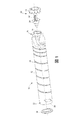
図1は本教示の実施形態に従ったトナー容器アセンブリ10、およびプリンタの一部とすることができるディスペンスオーガアセンブリ40を示す。
FIG. 1 illustrates a
トナー容器アセンブリ10は、容器12のディスペンス端部16にディスペンス開口部14を有する容器12、容器12の充填端部22における充填開口部20内に使用中配置されるトナー充填栓18、および使用中、ディスペンス開口部14内に配置されるシールアセンブリ24を含むことができる。容器12の表面は、1つまたは複数の表面溝26を含むことができる。
The
ディスペンスオーガアセンブリ40は、公知のプリンタ構造に従って、ディスペンスオーガ42および容器駆動連結体44を含む。
使用の前に、容器12は充填開口部20を通してトナー90(図4)を充填され、容器12内にトナー90を保持するように、トナー充填栓18は充填開口部20の中に設置される。トナー容器アセンブリ10は、オーガ管42がディスペンス開口部14を通って容器12に入ることを可能にしているオーガアセンブリ40上に設置される。オーガアセンブリ40は、ディスペンスオーガ42がシールアセンブリ24の開口部を通して容器12の中に伸びるように配置される。使用中に、容器および/またはディスペンスオーガ42は容器12内のトナーがディスペンスオーガ42によってすくい上げられプリントエンジンに輸送されるように回転する(簡潔にするために個別に示さない)。使用中に、1つまたは複数の表面溝26は、容器12の回転の間にトナーをディスペンス端部16およびディスペンスオーガ42の方へ促すのを助ける。
Prior to use, the
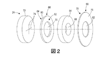
本教示の実施形態によるシールアセンブリ24は、図2の分解概略斜視描写に示される。シールアセンブリ24は、それを通る穴62および内側面上に接着剤78を有する外側の保持リング60、それを通る穴66を有する発泡体リング64、それを通る穴70を有する両面接着リング68、およびそれを通る1対の交差するスリット74(すなわち、十字型スリット)を有する固形発泡体ディスク72を含む。図3は固形発泡体ディスク72側から見たときの組み立てられたシールアセンブリ24を示す。固形発泡体ディスク72の主要な表面は両面接着リング68に物理的に接触する。発泡体リング64の主要な表面は外側の保持リング60の内側表面の接着剤78に物理的に接触する。外側の保持リング60は片側のみに接着剤78を有し、したがって、接着剤78を含む片面接着リングである。
A
約12mmから18mmまでの、例えば約15mmの直径を有するディスペンスオーガ42とのシールアセンブリ24の例示的な使用法を以下に説明する。シールアセンブリ24の個別の要素のそれぞれのサイズは容器12およびオーガアセンブリ40の具体的な個別の構成によって異なることは理解されるであろう。
An exemplary use of
外側の保持リング60上の接着剤78は発泡体リング64の主要な面に接着される。外側の保持リング60上の接着剤78は、完成したシールアセンブリ24を容器12におよび、より具体的には、ディスペンス開口部14を画定する容器縁28に接着するために使用される。そのようなものとして、外側の保持リング60の直径は他のシールアセンブリ構成要素64、68、72のいずれの外径よりも大きいであろう。例えば、外側の保持リング60は約38mmから約44mmまでの、例えば約41mmの外径を有することができる。リング60を通る開口部62は、両面接着リング68の直径より小さいが、発泡体リング64を通る開口部66の直径より大きい直径を有することができる。例えば、外側の保持リング60を通る開口部62は約17mmから約23mmまで、例えば約20mmとすることができる。外側の保持リング60は、非接着性のキャリア材76、およびキャリア材76の片側の主要な表面上の接着剤層78を含むことができる。例えば、非接着性のキャリア材76はポリエチレンテレフタレート(PET)などのポリマーまたはMylar(登録商標)(デラウェア州、ウィルミントンのE.I.DuPont de Nemours,Inc.から入手可能)などの二軸延伸ポリエチレンテレフタレートポリエステル樹脂フィルムとすることができる。接着剤層78はアクリル接着剤または圧力接着剤、熱硬化性(thermoset)接着剤、熱可塑性接着剤、熱硬化性(heat−curable)接着剤などの他の接着剤とすることができる。外側の保持リング60は約0.25mmから約0.75mmまでの、例えば約0.5mmの厚さを有することができる。
The
発泡体リング64は、発泡体材料、例えばポリエチレン発泡体、ウレタン発泡体などのポリマー発泡体を含むように製造することができる。発泡体リング64は約29mmから約35mmまでの、例えば約32mmの外径を有することができる。発泡体リング64は約4mmから約8mmまでの、例えば約6mmの厚さを有することができる。
The
一般に、発泡体リング64を通る開口部66は、ディスペンスオーガ42の断面形状と一致する形状、およびディスペンスオーガ42の幅または直径とほぼ同じかまたはそれより少し小さい幅または直径を有するであろう。発泡体リング64を通る開口部66は約5mmから約11mmまで、例えば約8mmとすることができる。
Generally, the
両面接着リング68は接着剤80の単一層とすることができる。もう1つの実施形態において、両面接着リング68は、キャリア80の第1の側(すなわち、第1の主要な表面)上に第1の接着剤層82およびキャリア80の第2の側(すなわち、第2の主要な表面)上に第2の接着剤層84を有する非接着性のキャリア80を含むことができる。両面接着リング68は発泡体リング64を固形発泡体ディスク72の主要な表面に接着するであろう。両面接着リング68は約29mmから約35mmまでの、例えば約32mmの外径を有することができる。両面接着リング68を通る開口部70は、外側の保持リング60を通る開口部62とほぼ同じサイズとすることができ、約17mmから約23mmまで、または約20mmとすることができる。両面接着リング68は0.1mmから約0.3mmまで、または約0.2mmの厚さを有することができる。キャリアの使用を含む実施形態において、非接着性のキャリア材80はポリエチレンテレフタレート(PET)などのポリマーまたはMylar(登録商標)などの二軸延伸ポリエチレンテレフタレートポリエステル樹脂フィルムとすることができる。キャリアの実施形態、または独立型接着剤の実施形態のいずれにおいても、接着剤はアクリル接着剤または圧力接着剤、熱硬化性(thermoset)接着剤、熱可塑性接着剤、熱硬化性(heat−curable)接着剤などの他の接着剤とすることができる。
The double-sided
固形発泡体ディスク72は、発泡体材料、例えばポリエチレン発泡体、ウレタン発泡体などのポリマー発泡体を含むように製造することができる。固形発泡体ディスク72は約29mmから約35mまで、または約32mmの外径を有することができる。固形発泡体ディスク72を通るそれぞれのスリット74は約10mmから約20mmまで、または約13mmから約18mmまで、または約15.5mmの長さ、あるいは使用中にディスペンスオーガ42の挿入および引出しから固形発泡体ディスク72への損傷が生じないために十分なサイズの長さを有することができる。2つのスリット74は、図示されるように、互いにほぼ垂直としそれぞれのスリット74の中央で交差することができる。固形発泡体ディスク72はちょうど2つのスリット74を含んでもよいし、2つより多いスリット74を含んでもよい。実施形態において、2つ以上のスリットは直線または曲線とすることができる。固形発泡体ディスク72は約4mmから約8mmまでの、例えば約6mmの厚さを有することができる。
The
したがって、上述のように、発泡体リング64、両面接着リング68、および固形発泡体ディスク72のそれぞれは、ほぼ等しい外径を有することができ、それぞれの外径はディスペンス開口部14の直径とほぼ等しい。もう1つの実施形態において、両面接着リング68が使用中に構造物68、72を互いに接着するのに十分な限り、両面接着リング68の外径は発泡体リング64および固形発泡体ディスク72の外径より小さくすることができる。
Thus, as mentioned above, each of the
図4に示されるように、容器12の使用中、シールアセンブリ24はトナー容器12の開口部14内に配置される。シールアセンブリ24はトナー90を容器12内に封じ込めて、出荷および保管の間、ならびにプリンタへの取付け、通常の使用、および交換の間のプリンタからの除去の間、容器12からのトナー90の漏れを減少させまたは防止する。開口部62、66、および70のそれぞれ、ならびにスリット74のそれぞれの中央は、シールアセンブリ24の軸92に沿って互いに整列し、軸は、外側の保持リング60の主要な表面、発泡体リング64の主要な表面、両面接着リング68の主要な表面、および固形発泡体ディスク72の主要な表面に垂直をなしている。固形発泡体ディスク72内のスリット74を画定する固形発泡体ディスク72の内側のエッジは、トナー90を容器12内に封じ込めるために互いに接触する。発泡体リング64内の開口部66の直径はスリット74の長さより小さいので、発泡体リング64はスリット74のそれぞれの外側の範囲(例えばそれぞれの端)を封ずる。トナー90を分配するために、図5に示すように、ディスペンスオーガ42は、外側の保持リング60を通る開口部62へ、発泡体リング64を通る開口部66へ、両面接着リング68を通る開口部70へ、および固形発泡体ディスク72を通るスリット74へ挿入される。トナー容器12の交換の間に、ディスペンスオーガはシールアセンブリ24のさまざまな開口部およびスリットから引出される。
As shown in FIG. 4, during use of the
スリットシールアセンブリのみを使用する従来のトナー容器用シールアセンブリと対照的に、本教示の実施形態によるシールアセンブリは、その中に開口部66を有する発泡体リング64に両面接着リング68で取り付けられた、その中に少なくとも2つのスリットを有する固形発泡体ディスク72を含む。発泡体リング64の開口部66はディスペンスオーガ42の幅とほぼ同じサイズのまたはそれより小さい幅または直径を有する。発泡体リング64は、トナー容器アセンブリの輸送および保管、ディスペンスオーガ42のシールアセンブリ24への挿入、プリンタ内でのトナー容器アセンブリの使用、およびシールアセンブリ24からのディスペンスオーガ42の引出しの間に、トナー90がスリットの端で漏れるのを防ぐように、スリット74の端に接触して置かれる。さらに、発泡体リング64は、固形発泡体ディスク72とディスペンスオーガ42の不完全な接触の任意の他の領域の間からのトナー90の漏れを減少させるまたは防止するようにディスペンスオーガ42の周りに円周状シールを提供する。
In contrast to a conventional toner container seal assembly using only a slit seal assembly, a seal assembly according to an embodiment of the present teachings is attached by a double-sided
本教示に従ってシールアセンブリ24を製造するためにさまざまな技術が使用できることは、本明細書の説明から当業者には明らかであろう。
It will be apparent to those skilled in the art from the description herein that various techniques can be used to manufacture
図面は、他の構造物が追加されてもよく現在の構造物が削除または修正されてもよい、一般化された概略の具体例を表すことが理解されるであろう。例えば、両面接着リング68は、固形発泡体ディスク72が発泡体リング64に十分に取り付けられる限り、接着リングでない別の接着剤層とすることができる。
It will be appreciated that the drawings represent generalized schematic examples, in which other structures may be added and current structures may be deleted or modified. For example, double-sided
図6は本教示の実施形態を含むプリンタ100を示す。プリンタ100は、その中にシールアセンブリ24を含む少なくとも1つのトナー容器10(図1)が設置されていて、トナー容器10を収納するプリンタ筐体102を含む。動作中に、トナー90(図5)はトナー容器10から、例えばディスペンスオーガアセンブリ40(図1)を使用して、プリントエンジン104に移送される。プリントエンジン104は、トナー90から紙シート、プラスチックなどの印刷媒体110上にテキストおよび/または画像108を作り出すようにデジタル命令およびプリンタ制御パネル106からのユーザ入力に従って運転される。
FIG. 6 shows a
本教示の広い適用範囲を明記している数値範囲およびパラメータは近似であるにもかかわらず、具体的な実施例で明記された数値は可能な限り正確に報告される。しかしながら、任意の数値は、各試験測定においてみられる標準偏差から必然的に生じる一定の誤差を本質的に含有する。さらに、本明細書に開示されたすべての範囲は、その中に包括された任意のおよびすべての部分範囲を包含すると理解されるべきである。例えば、「10未満」という範囲は、最小値のゼロと最大値の10との間の(およびこれらを含む)任意のおよびすべての部分範囲、すなわち、例えば1から5までなど、ゼロ以上の最小値および10以下の最大値を有する任意のおよびすべての部分範囲を含むことができる。一定の場合において、パラメータとして定められた数値は負値をとることができる。この場合、「10未満」として定められた範囲の例値は、例えば、−1、−2、−3、−10、−20、−30などの負値を想定することができる。 Notwithstanding that the numerical ranges and parameters setting forth the broad scope of the present teachings are approximations, the numerical values set forth in the specific examples are reported as precisely as possible. However, any numerical value inherently contains certain errors necessarily resulting from the standard deviation found in each test measurement. Further, all ranges disclosed herein should be understood to encompass any and all subranges subsumed therein. For example, the range "less than 10" is any and all subranges between (and including) the minimum value of zero and the maximum value of 10, ie, a minimum of zero or more, such as, for example, 1 to 5 It can include any and all subranges having a value and a maximum value of 10 or less. In certain cases, the numeric value defined as the parameter can be negative. In this case, for example, negative values such as -1, -2, -3, -10, -20, -30 can be assumed as the example value of the range defined as "less than 10".
本教示は1つまたは複数の実施に関して例示してきたが、添付の特許請求の範囲の精神および範囲から逸脱することなく、例示された実施例に変更および/または修正がなされ得る。例えば、プロセスは一連の動作または事象として説明されるが、本教示はこのような動作または事象の順序性によって限定されないことは、理解されるであろう。本明細書で説明されたもの以外に、いくつかの動作は異なった順序でおよび/または他の動作または事象と同時に起こることがある。同様に、本教示の1つまたは複数の実施態様または実施形態に従って方法論を実施するためにすべてのプロセス段階が必要とされるとは限らない。構造的な構成要素および/または処理段階が追加できること、あるいは現在の構造的な構成要素および/または処理段階が削除または修正できることは、理解されるであろう。さらに、本明細書に示された1つまたは複数の動作は、1つまたは複数の別個の動作および/または段階で遂行することができる。そのうえ、用語「含む(including)」、「含む(includes)」、「有する(having)」、「有する(has)」、「有する(with)」、またはそれらの変形が詳細な説明および特許請求の範囲のいずれかで使用される限り、そのような用語は用語「備える(comprising)」と同様に包括的であることが意図される。用語「のうちの少なくとも1つ」は、列挙された項目のうちの1つまたは複数が選択できることを意味するように使用される。さらに、本明細書の議論および特許請求の範囲において、一方が他方の「上(on)」にある、2つの物質に関して使用される用語「上(on)」は、物質間の少なくともいくらかの接触を意味し、他方「上(over)」は、接触が可能であるが必要とされないように、物質は近接しているが、おそらく1つまたは複数のさらなる介在物質があることを意味する。本明細書で使用される「上(on)」と「上(over)」のいずれも、方向性を意味しない。用語「コンフォーマル(conformal)」は、下にある物質の角度がコンフォーマルな物質によって維持される被覆材を記述する。用語「約(about)」は、変更が、例示された実施形態にプロセスまたは構造の不適合をもたらさない限り、列挙された値をいくぶん変更できることを示す。最後に、「例示的(exemplary)」は、その説明が理想であることを暗示するよりむしろ、実施例として使用されることを示す。本教示の他の実施形態は、本明細書に開示の仕様および実施を考慮することにより当業者に明らかであろう。本教示の真の範囲および精神は以下の特許請求の範囲によって示され、明細および実施例は例示としてのみ考慮されることを意図している。 While the present teachings have been illustrated in connection with one or more implementations, changes and / or modifications can be made to the illustrated embodiments without departing from the spirit and scope of the appended claims. For example, although a process is described as a series of acts or events, it will be understood that the present teachings are not limited by the order of such acts or events. In addition to those described herein, some operations may occur in different orders and / or concurrently with other operations or events. Similarly, not all process steps may be required to implement a methodology in accordance with one or more embodiments or embodiments of the present teachings. It will be appreciated that structural components and / or processing steps can be added, or that current structural components and / or processing steps can be deleted or modified. Additionally, one or more of the operations set forth herein may be performed in one or more separate operations and / or stages. Moreover, the terms "including", "includes", "having", "has", "with" or variations thereof are described in detail and in the claims. As used in any of the ranges, such terms are intended to be as inclusive as the term "comprising". The term "at least one of" is used to mean that one or more of the listed items can be selected. Furthermore, in the discussion and claims herein, the term "on" used in reference to two substances, one being "on" the other, is at least some contact between the substances. On the other hand, "over" means that the substances are in close proximity, but possibly with one or more further interventions, so that contact is possible but not required. As used herein, "on" and "over" do not imply directionality. The term "conformal" describes a dressing in which the angle of the underlying material is maintained by the conformal material. The term "about" indicates that the values recited may be altered somewhat as long as the alteration does not result in process or structural incompatibility in the illustrated embodiment. Finally, "exemplary" indicates that the description is used as an example, rather than implying that it is ideal. Other embodiments of the present teachings will be apparent to those skilled in the art from consideration of the specification and practice disclosed herein. The true scope and spirit of the present teachings are set forth by the following claims, and the specification and examples are intended to be considered as exemplary only.
本出願で使用される相対的位置の用語は、加工物の向きにかかわらず、加工物の従来の平面または加工表面に平行な平面に基づき定義される。本出願で使用される「水平」または「横方向」という用語は、加工物の向きにかかわらず、加工物の従来の平面または加工表面に平行な平面として定義される。「垂直」という用語は水平面と垂直に交わる方向を意味する。「上(on)」、「側(side)」(「側壁(sidewall)」にあるように)、「より高い(higher)」「より低い(lower)」「上(over)」「最上部(top)」および「下(under)」などの用語は、加工物の方向にかかわらず、加工物の最上面上にある従来の平面または加工表面に関して定義される。 The term relative position as used in the present application is defined on the basis of a plane parallel to the conventional plane or work surface of the workpiece, regardless of the orientation of the workpiece. The terms "horizontal" or "lateral" as used in the present application are defined as a plane parallel to the conventional plane or work surface of the workpiece, regardless of the orientation of the workpiece. The term "vertical" means the direction perpendicular to the horizontal plane. 'On', 'side' (as in 'sidewall'), 'higher', 'lower', 'over', 'top' Terms such as "top" and "under" are defined with respect to a conventional flat or work surface on the top surface of the work, regardless of the direction of the work.
Claims (15)
外側の保持リングであって、非接着性キャリアと、前記非接着性キャリアの表面上の第1の接着剤層と、前記外側の保持リングを通る第1の開口部とを備え、38mmから44mmまでの外径を有する、外側の保持リングと、
発泡体リングであって、前記発泡体リングを通る第2の開口部を備え、前記発泡体リングは前記第1の接着剤層で前記外側の保持リングに取り付けられ、29mmから35mmまでの外径を有する、発泡体リングと、
前記発泡体リングに取り付けられる両面接着剤リングであって、前記両面接着剤リングを通る第3の開口部を備え、29mmから35mmまでの外径を有する、前記両面接着剤リングと、
固形発泡体ディスクであって、前記固形発泡体ディスクを通る第1のスリットと、前記固形発泡体ディスクを通る第2のスリットと、前記両面接着剤リングに物理的に接触する主要な表面とを備え、29mmから35mmまでの外径を有する、固形発泡体ディスクと、
を備え、
前記第1のスリットは前記第2のスリットに垂直であり、前記固形発泡体ディスクは前記両面接着剤リングによって前記発泡体リングに取り付けられ、
前記第1の開口部、前記第2の開口部、前記第3の開口部、前記第1のスリットの中心および前記第2のスリットの中心は、前記固形発泡体ディスクの前記主要な表面と垂直な軸に沿ってほぼ整列される、トナー容器アセンブリ。 A toner container assembly for a printer, the toner container assembly comprising a seal assembly, the seal assembly comprising:
An outer retaining ring comprising a non-adhesive carrier, a first adhesive layer on the surface of the non-adhesive carrier, and a first opening through the outer retaining ring, 38 mm to 44 mm An outer retaining ring, having an outer diameter of up to
A foam ring comprising a second opening through the foam ring, the foam ring being attached to the outer retaining ring with the first adhesive layer and having an outer diameter of 29 mm to 35 mm With a foam ring,
A double-sided adhesive ring attached to the foam ring, comprising a third opening through the double-sided adhesive ring and having an outer diameter of 29 mm to 35 mm;
A solid foam disk, comprising: a first slit passing through the solid foam disk; a second slit passing through the solid foam disk; and a major surface physically contacting the double-sided adhesive ring A solid foam disc, having an outer diameter of from 29 mm to 35 mm;
Equipped with
The first slit is perpendicular to the second slit, and the solid foam disc is attached to the foam ring by the double-sided adhesive ring
The first opening, the second opening, the third opening, the center of the first slit and the center of the second slit are perpendicular to the main surface of the solid foam disc A toner container assembly that is substantially aligned along an axis.
ディスペンス端部に開口部を備えるトナー容器をさらに備え、
前記シールアセンブリは前記トナー容器の前記開口部内に配置され、
前記シールアセンブリは前記外側の保持リングおよび前記第1の接着剤層を使用して前記トナー容器に取り付けられる、トナー容器アセンブリ。 A toner container assembly according to claim 1, wherein
The toner container further comprises an opening at the dispensing end,
The seal assembly is disposed within the opening of the toner container;
A toner container assembly, wherein the seal assembly is attached to the toner container using the outer retaining ring and the first adhesive layer.
前記両面接着剤リングは0.1mmから0.3mmまでの厚さを有し、
前記発泡体リングは4mmから8mmまでの厚さを有し、
前記固形発泡体ディスクは4mmか8mmまでの厚さを有し、
前記第1のスリット及び前記第2のスリットの夫々は10mmから20mmまでの長さを有する、
請求項1に記載のトナー容器アセンブリ。 The outer retaining ring has a thickness of 0.25 mm to 0.75 mm,
The double-sided adhesive ring has a thickness of 0.1 mm to 0.3 mm,
The foam ring has a thickness of 4 mm to 8 mm,
The solid foam disc has a thickness of up to 4 mm or 8 mm,
Each of the first slit and the second slit has a length of 10 mm to 20 mm,
A toner container assembly according to claim 1.
前記発泡体リングを通る前記第2の開口部は5mmから11mmまでの直径を有し、
前記両面接着剤リングを通る前記第3の開口部は17mmから23mmまでの直径を有する、
請求項3に記載のトナー容器アセンブリ。 The first opening through the outer retaining ring has a diameter of 17 mm to 23 mm,
The second opening through the foam ring has a diameter of 5 mm to 11 mm,
The third opening through the double-sided adhesive ring has a diameter of 17 mm to 23 mm,
The toner container assembly of claim 3.
外側の保持リングであって、非接着性キャリアと、前記非接着性キャリアの表面上の第1の接着剤層と、前記外側の保持リングを通る第1の開口部とを備える、外側の保持リングと、
発泡体リングであって、前記発泡体リングを通る第2の開口部を備え、前記発泡体リングは前記第1の接着剤層で前記外側の保持リングに取り付けられる、発泡体リングと、
前記発泡体リングに取り付けられる両面接着剤層と、
固形発泡体ディスクであって、前記固形発泡体ディスクを通る第1のスリットと前記固形発泡体ディスクを通る第2のスリットとを備え、前記第1のスリットは前記第2のスリットに垂直であり、前記固形発泡体ディスクは前記両面接着剤層によって前記発泡体リングに取り付けられる、固形発泡体ディスクと、
を備える、トナー容器アセンブリと、
前記外側の保持リングを通る前記第1の開口部内、前記発泡体リングを通る前記第2の開口部内、および前記両面接着剤層を通る第3の開口部内に配置されるディスペンスオーガと、
前記トナー容器アセンブリを収納するプリンタ筐体と、
を備える、プリンタ。 A toner container assembly comprising a seal assembly, the seal assembly comprising:
An outer retaining ring comprising a non-adhesive carrier, a first adhesive layer on the surface of the non-adhesive carrier, and a first opening through the outer retaining ring. With the ring,
A foam ring comprising a second opening through the foam ring, the foam ring being attached to the outer retaining ring with the first adhesive layer;
A double sided adhesive layer attached to the foam ring;
A solid foam disc comprising a first slit passing through the solid foam disc and a second slit passing through the solid foam disc, the first slit being perpendicular to the second slit A solid foam disc, wherein said solid foam disc is attached to said foam ring by means of said double-sided adhesive layer;
A toner container assembly comprising:
A dispense auger disposed in the first opening through the outer retaining ring, in the second opening through the foam ring, and in a third opening through the double-sided adhesive layer;
A printer housing for housing the toner container assembly;
With a printer.
ディスペンス端部に開口部を備えるトナー容器をさらに備え、
前記シールアセンブリは前記トナー容器の前記開口部内に配置され、
前記シールアセンブリは前記外側の保持リングおよび前記第1の接着剤層を使用して前記トナー容器に取り付けられる、プリンタ。 The printer according to claim 6, wherein
The toner container further comprises an opening at the dispensing end,
The seal assembly is disposed within the opening of the toner container;
The printer, wherein the seal assembly is attached to the toner container using the outer retaining ring and the first adhesive layer.
前記固形発泡体ディスクの主要な表面は前記両面接着剤リングに物理的に接触し、
前記第1の開口部、前記第2の開口部、前記第3の開口部、前記第1のスリットの中心および前記第2のスリットの中心は、前記固形発泡体ディスクの前記主要な表面と垂直な軸に沿ってほぼ整列される、
請求項6に記載のプリンタ。 The double-sided adhesive layer is a double-sided adhesive ring, the double-sided adhesive ring comprising a third opening passing through the double-sided adhesive ring,
The major surface of the solid foam disc is in physical contact with the double-sided adhesive ring,
The first opening, the second opening, the third opening, the center of the first slit and the center of the second slit are perpendicular to the main surface of the solid foam disc Generally aligned along a common axis,
The printer according to claim 6.
前記両面接着剤リングは29mmから35mmまでの外径を有し、
前記発泡体リングは29mmから35mmまでの外径を有し、
前記固形発泡体ディスクは29mmから35mmまでの外径を有する、
請求項8に記載のプリンタ。 The outer retaining ring has an outer diameter of 38 mm to 44 mm,
The double-sided adhesive ring has an outer diameter of 29 mm to 35 mm,
The foam ring has an outer diameter of 29 mm to 35 mm,
The solid foam disc has an outer diameter of 29 mm to 35 mm,
The printer according to claim 8.
前記両面接着剤リングは0.1mmから0.3mmまでの厚さを有し、
前記発泡体リングは4mmから8mmまでの厚さを有し、
前記固形発泡体ディスクは4mmか8mmまでの厚さを有し、
前記第1のスリット及び前記第2のスリットの夫々は10mmから20mmまでの長さを有する、
請求項8に記載のプリンタ。 The outer retaining ring has a thickness of 0.25 mm to 0.75 mm,
The double-sided adhesive ring has a thickness of 0.1 mm to 0.3 mm,
The foam ring has a thickness of 4 mm to 8 mm,
The solid foam disc has a thickness of up to 4 mm or 8 mm,
Each of the first slit and the second slit has a length of 10 mm to 20 mm,
The printer according to claim 8.
前記発泡体リングを通る前記第2の開口部は5mmから11mmまでの直径を有し、
前記両面接着剤リングを通る前記第3の開口部は17mmから23mmまでの直径を有する、
請求項10に記載のプリンタ。 The first opening through the outer retaining ring has a diameter of 17 mm to 23 mm,
The second opening through the foam ring has a diameter of 5 mm to 11 mm,
The third opening through the double-sided adhesive ring has a diameter of 17 mm to 23 mm,
The printer according to claim 10.
前記ディスペンスオーガが、前記トナーを前記プリントエンジンに輸送するように構成される、
請求項13に記載のプリンタ。 The printer further comprises a print engine housed in the printer housing,
The dispense auger is configured to transport the toner to the print engine;
The printer according to claim 13.
外側の保持リングであって、非接着性キャリアと、前記非接着性キャリアの表面上の第1の接着剤層と、前記外側の保持リングを通る第1の開口部とを備え、0.25mmから0.75mmまでの厚さを有する、外側の保持リングと、
発泡体リングであって、前記発泡体リングを通る第2の開口部を備え、前記発泡体リングは前記第1の接着剤層で前記外側の保持リングに取り付けられ、4mmから8mmまでの厚さを有する、発泡体リングと、
前記発泡体リングに取り付けられる両面接着剤リングであって、前記両面接着剤リングを通る第3の開口部を備え、0.1mmから0.3mmまでの厚さを有する、両面接着剤リングと、
固形発泡体ディスクであって、前記固形発泡体ディスクを通る第1のスリットと、前記固形発泡体ディスクを通る第2のスリットと、前記両面接着剤リングに物理的に接触する主要な表面とを備える固形発泡体ディスクと、
を備え、
前記固形発泡体ディスクは4mmか8mmまでの厚さを有し、
前記第1のスリット及び前記第2のスリットの夫々は10mmから20mmまでの長さを有し、
前記第1のスリットは前記第2のスリットに垂直であり、前記固形発泡体ディスクは前記両面接着剤リングによって前記発泡体リングに取り付けられ、
前記第1の開口部、前記第2の開口部、前記第3の開口部、前記第1のスリットの中心および前記第2のスリットの中心は、前記固形発泡体ディスクの前記主要な表面と垂直な軸に沿ってほぼ整列される、トナー容器アセンブリ。 A toner container assembly for a printer, the toner container assembly comprising a seal assembly, the seal assembly comprising:
An outer retaining ring comprising a non-adhesive carrier, a first adhesive layer on the surface of the non-adhesive carrier, and a first opening through the outer retaining ring, 0.25 mm An outer retaining ring, having a thickness from
A foam ring comprising a second opening through the foam ring, the foam ring being attached to the outer retaining ring with the first adhesive layer and having a thickness of 4 mm to 8 mm With a foam ring,
A double-sided adhesive ring attached to the foam ring, comprising a third opening through the double-sided adhesive ring, having a thickness of 0.1 mm to 0.3 mm;
A solid foam disk, comprising: a first slit passing through the solid foam disk; a second slit passing through the solid foam disk; and a major surface physically contacting the double-sided adhesive ring A solid foam disc,
Equipped with
The solid foam disc has a thickness of up to 4 mm or 8 mm,
Each of the first slit and the second slit has a length of 10 mm to 20 mm,
The first slit is perpendicular to the second slit, and the solid foam disc is attached to the foam ring by the double-sided adhesive ring
The first opening, the second opening, the third opening, the center of the first slit and the center of the second slit are perpendicular to the main surface of the solid foam disc A toner container assembly that is substantially aligned along an axis.
Applications Claiming Priority (2)
| Application Number | Priority Date | Filing Date | Title |
|---|---|---|---|
| US14/486,036 US9217956B1 (en) | 2014-09-15 | 2014-09-15 | Dispense-end seal for toner containers |
| US14/486,036 | 2014-09-15 |
Publications (3)
| Publication Number | Publication Date |
|---|---|
| JP2016062098A JP2016062098A (en) | 2016-04-25 |
| JP2016062098A5 JP2016062098A5 (en) | 2018-10-04 |
| JP6550303B2 true JP6550303B2 (en) | 2019-07-24 |
Family
ID=54847948
Family Applications (1)
| Application Number | Title | Priority Date | Filing Date |
|---|---|---|---|
| JP2015172176A Active JP6550303B2 (en) | 2014-09-15 | 2015-09-01 | Toner container dispense end seal |
Country Status (7)
| Country | Link |
|---|---|
| US (1) | US9217956B1 (en) |
| JP (1) | JP6550303B2 (en) |
| KR (1) | KR102201836B1 (en) |
| CN (1) | CN105425561B (en) |
| DE (1) | DE102015216644B4 (en) |
| RU (1) | RU2671104C2 (en) |
| TW (1) | TWI661948B (en) |
Families Citing this family (2)
| Publication number | Priority date | Publication date | Assignee | Title |
|---|---|---|---|---|
| JP6692516B2 (en) * | 2017-03-23 | 2020-05-13 | 京セラドキュメントソリューションズ株式会社 | Toner transport device and image forming apparatus including the toner transport device |
| EP4235308A1 (en) * | 2021-12-07 | 2023-08-30 | General Plastic Industrial Co., Ltd. | Power cartridge coupling mechanism |
Family Cites Families (20)
| Publication number | Priority date | Publication date | Assignee | Title |
|---|---|---|---|---|
| US4599851A (en) * | 1984-10-04 | 1986-07-15 | Marpac Industries, Inc. | Dry toner cartridge system and method of filling same |
| JPH0658569B2 (en) * | 1987-07-13 | 1994-08-03 | コニカ株式会社 | Developer container |
| JP3776958B2 (en) * | 1995-09-11 | 2006-05-24 | 大日本印刷株式会社 | Toner container lid film and toner container |
| TWI227815B (en) * | 1998-12-22 | 2005-02-11 | Ricoh Kk | Toner container and image forming method and apparatus using the same |
| US6137972A (en) * | 1999-08-30 | 2000-10-24 | Xerox Corporation | Imaging material dispensing system |
| JP2001072100A (en) * | 1999-09-06 | 2001-03-21 | Ricoh Co Ltd | Powder replenishing container and powder replenishing device |
| JP2002072650A (en) * | 2000-09-01 | 2002-03-12 | Ricoh Co Ltd | Developer storing container and image forming device |
| JP3958511B2 (en) | 2000-09-28 | 2007-08-15 | 株式会社リコー | Toner supply device and image forming apparatus |
| US6363232B1 (en) * | 2000-10-10 | 2002-03-26 | Xerox Corporation | Developer material cartridge having a robust multiple function seal |
| ES2383157T3 (en) * | 2001-02-19 | 2012-06-18 | Canon Kabushiki Kaisha | Toner supply container |
| DE20321859U1 (en) * | 2002-09-20 | 2011-12-16 | Ricoh Company, Ltd. | Image forming apparatus, powder feeder unit, toner containers and powder containers |
| JP2004191851A (en) * | 2002-12-13 | 2004-07-08 | Ricoh Co Ltd | Toner stirring device, toner carrying device and electrophotographic image forming apparatus |
| JP3948400B2 (en) * | 2002-12-19 | 2007-07-25 | 富士ゼロックス株式会社 | Image forming apparatus, toner collection bottle |
| JP4241172B2 (en) * | 2003-05-06 | 2009-03-18 | 株式会社リコー | Toner supply device and image forming apparatus |
| JP2006145873A (en) * | 2004-11-19 | 2006-06-08 | Ricoh Co Ltd | Seal structure of developer container, developer container, and image forming apparatus |
| JP2006235360A (en) * | 2005-02-25 | 2006-09-07 | Kyocera Mita Corp | Developing unit |
| JP4698694B2 (en) * | 2008-03-17 | 2011-06-08 | 株式会社リコー | Toner cartridge |
| KR101410388B1 (en) * | 2010-03-17 | 2014-06-23 | 가부시키가이샤 리코 | Cap, developer container, developer supply device, and image forming apparatus |
| JP5931711B2 (en) | 2012-12-21 | 2016-06-08 | 京セラドキュメントソリューションズ株式会社 | Photosensitive drum, image forming apparatus, and vibration-proof structure |
| JP5565714B2 (en) * | 2013-07-26 | 2014-08-06 | 株式会社リコー | Toner container, image forming apparatus, toner container manufacturing method, and toner container recycling method. |
-
2014
- 2014-09-15 US US14/486,036 patent/US9217956B1/en active Active
-
2015
- 2015-08-17 TW TW104126747A patent/TWI661948B/en active
- 2015-08-26 KR KR1020150120050A patent/KR102201836B1/en active IP Right Grant
- 2015-08-31 CN CN201510548510.7A patent/CN105425561B/en active Active
- 2015-08-31 DE DE102015216644.9A patent/DE102015216644B4/en active Active
- 2015-09-01 JP JP2015172176A patent/JP6550303B2/en active Active
- 2015-09-07 RU RU2015137940A patent/RU2671104C2/en active
Also Published As
| Publication number | Publication date |
|---|---|
| RU2015137940A3 (en) | 2018-09-24 |
| RU2015137940A (en) | 2017-03-15 |
| KR102201836B1 (en) | 2021-01-11 |
| JP2016062098A (en) | 2016-04-25 |
| CN105425561B (en) | 2018-06-05 |
| DE102015216644B4 (en) | 2021-06-17 |
| KR20160031956A (en) | 2016-03-23 |
| TW201609446A (en) | 2016-03-16 |
| RU2671104C2 (en) | 2018-10-29 |
| DE102015216644A1 (en) | 2016-03-17 |
| CN105425561A (en) | 2016-03-23 |
| TWI661948B (en) | 2019-06-11 |
| US9217956B1 (en) | 2015-12-22 |
Similar Documents
| Publication | Publication Date | Title |
|---|---|---|
| US9304441B2 (en) | Developer accommodating container, developer accommodating unit, process cartridge and image forming apparatus | |
| CN104820348B (en) | Developer reservoir, box and imaging device | |
| JP6550303B2 (en) | Toner container dispense end seal | |
| JP2013114037A (en) | Developer storage unit, process cartridge, electrophotographic image forming apparatus | |
| JP2014149511A5 (en) | Developer container, developing device, process cartridge, electrophotographic image forming apparatus | |
| US9229366B2 (en) | Developer storage container and image forming apparatus provided with same | |
| US10031440B2 (en) | Developing device and image forming member including a clearance closing member with grooves | |
| JP5891681B2 (en) | Developer cartridge | |
| JP4022351B2 (en) | Developer container | |
| JP6926950B2 (en) | Plug member, liquid storage unit | |
| JP2018091892A (en) | Developing device | |
| JP2005234164A (en) | Side seal structure for rotary body | |
| JP2016062098A5 (en) | ||
| US20190121258A1 (en) | Toner container, image forming apparatus | |
| JP2019132924A (en) | Toner cartridge | |
| JP2002072650A (en) | Developer storing container and image forming device | |
| JP2017173676A (en) | Developing unit | |
| JPS60146271A (en) | Developer vessel | |
| KR101745790B1 (en) | Removable device which can rotate for remove the sealing tape for tonor leak-proof | |
| JP2015219403A (en) | Developer housing body, image forming unit and image forming device | |
| US20160342111A1 (en) | Powder container, image forming apparatus, and transport member disposed therein | |
| JP6447483B2 (en) | Developing device, image forming apparatus | |
| JP2015105970A (en) | Developer cartridge, image forming unit, and image forming apparatus | |
| JP2014032425A5 (en) | ||
| JP2002169363A (en) | Toner cartridge |
Legal Events
| Date | Code | Title | Description |
|---|---|---|---|
| A521 | Request for written amendment filed |
Free format text: JAPANESE INTERMEDIATE CODE: A523 Effective date: 20180821 |
|
| A621 | Written request for application examination |
Free format text: JAPANESE INTERMEDIATE CODE: A621 Effective date: 20180821 |
|
| A871 | Explanation of circumstances concerning accelerated examination |
Free format text: JAPANESE INTERMEDIATE CODE: A871 Effective date: 20180821 |
|
| A975 | Report on accelerated examination |
Free format text: JAPANESE INTERMEDIATE CODE: A971005 Effective date: 20181105 |
|
| A977 | Report on retrieval |
Free format text: JAPANESE INTERMEDIATE CODE: A971007 Effective date: 20181105 |
|
| A131 | Notification of reasons for refusal |
Free format text: JAPANESE INTERMEDIATE CODE: A131 Effective date: 20181113 |
|
| A521 | Request for written amendment filed |
Free format text: JAPANESE INTERMEDIATE CODE: A523 Effective date: 20190130 |
|
| A131 | Notification of reasons for refusal |
Free format text: JAPANESE INTERMEDIATE CODE: A131 Effective date: 20190226 |
|
| A521 | Request for written amendment filed |
Free format text: JAPANESE INTERMEDIATE CODE: A523 Effective date: 20190520 |
|
| TRDD | Decision of grant or rejection written | ||
| A01 | Written decision to grant a patent or to grant a registration (utility model) |
Free format text: JAPANESE INTERMEDIATE CODE: A01 Effective date: 20190604 |
|
| A61 | First payment of annual fees (during grant procedure) |
Free format text: JAPANESE INTERMEDIATE CODE: A61 Effective date: 20190701 |
|
| R150 | Certificate of patent or registration of utility model |
Ref document number: 6550303 Country of ref document: JP Free format text: JAPANESE INTERMEDIATE CODE: R150 |
|
| R250 | Receipt of annual fees |
Free format text: JAPANESE INTERMEDIATE CODE: R250 |
|
| R250 | Receipt of annual fees |
Free format text: JAPANESE INTERMEDIATE CODE: R250 |