JP6549864B2 - Fuel cell stack - Google Patents
Fuel cell stack Download PDFInfo
- Publication number
- JP6549864B2 JP6549864B2 JP2015050496A JP2015050496A JP6549864B2 JP 6549864 B2 JP6549864 B2 JP 6549864B2 JP 2015050496 A JP2015050496 A JP 2015050496A JP 2015050496 A JP2015050496 A JP 2015050496A JP 6549864 B2 JP6549864 B2 JP 6549864B2
- Authority
- JP
- Japan
- Prior art keywords
- plate
- uneven portion
- fuel cell
- porous carbon
- cell stack
- Prior art date
- Legal status (The legal status is an assumption and is not a legal conclusion. Google has not performed a legal analysis and makes no representation as to the accuracy of the status listed.)
- Active
Links
Images


Classifications
-
- Y—GENERAL TAGGING OF NEW TECHNOLOGICAL DEVELOPMENTS; GENERAL TAGGING OF CROSS-SECTIONAL TECHNOLOGIES SPANNING OVER SEVERAL SECTIONS OF THE IPC; TECHNICAL SUBJECTS COVERED BY FORMER USPC CROSS-REFERENCE ART COLLECTIONS [XRACs] AND DIGESTS
- Y02—TECHNOLOGIES OR APPLICATIONS FOR MITIGATION OR ADAPTATION AGAINST CLIMATE CHANGE
- Y02E—REDUCTION OF GREENHOUSE GAS [GHG] EMISSIONS, RELATED TO ENERGY GENERATION, TRANSMISSION OR DISTRIBUTION
- Y02E60/00—Enabling technologies; Technologies with a potential or indirect contribution to GHG emissions mitigation
- Y02E60/30—Hydrogen technology
- Y02E60/50—Fuel cells
Description
本発明は、電解質膜の両側に電極が配設される電解質膜・電極構造体と、セパレータとを有する発電セルを備え、複数の前記発電セルが積層される積層体を設ける燃料電池スタックに関する。 The present invention relates to a fuel cell stack including a power generation cell having an electrolyte membrane-electrode assembly in which electrodes are disposed on both sides of an electrolyte membrane, and a separator, and a stack in which a plurality of power generation cells are stacked.
例えば、固体高分子型燃料電池は、高分子イオン交換膜からなる電解質膜の一方の面にアノード電極が、他方の面にカソード電極が、それぞれ配設された電解質膜・電極構造体(MEA)を備えている。電解質膜・電極構造体は、セパレータ(バイポーラ板)によって挟持されることにより、発電セルを構成している。燃料電池は、通常、所定の数の発電セルが積層されることにより、例えば、車載用燃料電池スタックとして燃料電池車両(燃料電池電気自動車等)に組み込まれている。 For example, in a polymer electrolyte fuel cell, an electrolyte membrane-electrode assembly (MEA) in which an anode is disposed on one side of an electrolyte membrane comprising a polymer ion exchange membrane and a cathode is disposed on the other side. Is equipped. The electrolyte membrane electrode assembly constitutes a power generation cell by being sandwiched by a separator (bipolar plate). For example, a fuel cell is incorporated into a fuel cell vehicle (fuel cell electric vehicle or the like) as a vehicle fuel cell stack, for example, by stacking a predetermined number of power generation cells.
燃料電池スタックでは、外部への放熱により他の発電セルに比べて温度低下が惹起され易い発電セルが存在している。例えば、積層方向端部に配置されている発電セル(以下、端部発電セルともいう)は、例えば、電力取り出し用ターミナルプレート(集電板)や、エンドプレート等からの放熱が多く、上記の温度低下が顕著になっている。 In fuel cell stacks, there are power generation cells in which a temperature drop is more likely to occur than in other power generation cells due to heat dissipation to the outside. For example, a power generation cell (hereinafter also referred to as an end power generation cell) disposed at the end in the stacking direction has a large heat dissipation from, for example, a terminal plate for power extraction (collector plate) or an end plate. The temperature drop is remarkable.
そこで、簡単な構成で、端部発電セルの温度低下を確実に阻止することを目的として、例えば、特許文献1に開示されている燃料電池スタックが提案されている。この燃料電池スタックでは、絶縁部材に凹部が形成されるとともに、前記凹部には、断熱部材及びターミナルプレートが収容され、且つ、前記断熱部材が前記ターミナルプレートと積層体との間に積層されることを特徴としている。 Therefore, for the purpose of reliably preventing the temperature decrease of the end power generation cell with a simple configuration, for example, a fuel cell stack disclosed in Patent Document 1 has been proposed. In the fuel cell stack, a recess is formed in the insulating member, the heat insulating member and the terminal plate are accommodated in the recess, and the heat insulating member is stacked between the terminal plate and the laminate. It is characterized by
本発明は、この種の技術に関連してなされたものであり、積層体の積層方向端部からの放熱を可及的に抑制することができ、良好な発電性能を確実に維持することが可能な燃料電池スタックを提供することを目的とする。 The present invention has been made in connection with this type of technology, and can suppress heat radiation from the end in the stacking direction of the laminate as much as possible, and reliably maintain good power generation performance. It aims to provide a possible fuel cell stack.
本発明に係る燃料電池スタックは、電解質膜の両側に電極が配設される電解質膜・電極構造体と、セパレータとを有する発電セルを備えている。複数の発電セルが積層される積層体の積層方向両端には、外方に向かってターミナルプレート、インシュレータ及びエンドプレートが配設されている。 A fuel cell stack according to the present invention includes a power generation cell having an electrolyte membrane / electrode assembly in which electrodes are disposed on both sides of an electrolyte membrane, and a separator. A terminal plate, an insulator, and an end plate are disposed outwardly at both ends in the stacking direction of the stack in which the plurality of power generation cells are stacked.
積層体の積層方向一端とターミナルプレートとの間には、断熱部材が介装されるとともに、前記断熱部材は、前記ターミナルプレートに接触する多孔質カーボンプレートを備えている。ターミナルプレートの多孔質カーボンプレートに対向するプレート面には、第1凹凸部が形成される一方、前記多孔質カーボンプレートの前記ターミナルプレートに対向するプレート面には、前記第1凹凸部と互いにかみ合う第2凹凸部が形成されている。そして、第1凹凸部と第2凹凸部とは、少なくとも一方の凹部底面と他方の凸部頂面とが当接して接触面を形成し、前記第1凹凸部を形成する凸部の両側面と前記第2凹凸部を形成する凹部の両側面とが互いに離間するとともに前記第1凹凸部を形成する凹部の両側面と前記第2凹凸部を形成する凸部の両側面とが互いに離間して空気層を形成する。
A heat insulating member is interposed between one end of the laminate in the stacking direction and the terminal plate, and the heat insulating member includes a porous carbon plate in contact with the terminal plate. A first uneven portion is formed on a plate surface facing the porous carbon plate of the terminal plate, while a plate surface facing the terminal plate of the porous carbon plate is engaged with the first uneven portion. A second uneven portion is formed. The first uneven portion and the second uneven portion are in contact with at least one of the recessed portion bottom surface and the other protruding portion top surface to form a contact surface, and both side surfaces of the protruding portion forming the first uneven portion. And both side surfaces of the concave portion forming the second uneven portion are separated from each other, and both side surfaces of the concave portion forming the first uneven portion and both side surfaces of the convex portion forming the second uneven portion are separated from each other It forms an air layer Te.
また、この燃料電池スタックでは、インシュレータは、積層体に向かって開口される凹部を設け、前記凹部には、少なくとも多孔質カーボンプレート及びターミナルプレートが収容されることが好ましい。 In the fuel cell stack, preferably, the insulator is provided with a recess opened toward the stack, and at least the porous carbon plate and the terminal plate are accommodated in the recess.
本発明によれば、ターミナルプレートのプレート面に形成された第1凹凸部と、多孔質カーボンプレートのプレート面に形成された第2凹凸部とは、互いにかみ合うことにより、接触面が形成されている。従って、熱伝導に起因するターミナルプレートと多孔質カーボンプレートとの接触面積が良好に削減されるため、端部発電セルから外部への放熱を抑制することができる。これにより、燃料電池スタックの発電不良を阻止し、良好な発電性能を確保するとともに、耐久性の向上を図ることが可能になる。 According to the present invention, the first uneven portion formed on the plate surface of the terminal plate and the second uneven portion formed on the plate surface of the porous carbon plate mesh with each other to form a contact surface. There is. Therefore, since the contact area of the terminal plate and porous carbon plate resulting from heat conduction is favorably reduced, it is possible to suppress heat radiation from the end portion power generation cell to the outside. As a result, generation failure of the fuel cell stack can be prevented, good power generation performance can be secured, and durability can be improved.
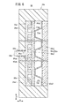
図1及び図2に示すように、本発明の第1の実施形態に係る燃料電池スタック10は、複数の発電セル12が水平方向(矢印A方向)又は重力方向(矢印C方向)に積層された積層体14を備える。燃料電池スタック10は、図示しないが、燃料電池電気自動車等の燃料電池車両に搭載される。
As shown in FIGS. 1 and 2, in the
積層体14の積層方向(矢印A方向)一端には、ターミナルプレート16a、インシュレータ(絶縁プレート)18a及びエンドプレート20aが外方に向かって、順次、配設される(図2参照)。積層体14の積層方向他端には、ターミナルプレート16b、インシュレータ(絶縁プレート)18b及びエンドプレート20bが外方に向かって、順次、配設される。ターミナルプレート16a、16bは、電気導電性を有する材料から構成され、例えば、銅、アルミニウム又はステンレススチール等の金属で構成される。
A
図1に示すように、エンドプレート20a、20bは、横長(縦長でもよい)の長方形状を有するとともに、各辺間には、連結バー24が配置される。各連結バー24は、両端をエンドプレート20a、20bの内面にボルト26を介して固定され、複数の積層された発電セル12に積層方向(矢印A方向)の締め付け荷重を付与する。なお、燃料電池スタック10では、エンドプレート20a、20bを端板とする筐体を備え、前記筐体内に積層体14を収容するように構成してもよい。
As shown in FIG. 1, the
発電セル12は、図3及び図4に示すように、樹脂枠付き電解質膜・電極構造体28が、第1セパレータ30及び第2セパレータ32により挟持される。第1セパレータ30及び第2セパレータ32は、例えば、鋼板、ステンレス鋼板、アルミニウム板、めっき処理鋼板、あるいはその金属表面に防食用の表面処理を施した金属薄板を波形にプレス成形して構成される。第1セパレータ30及び第2セパレータ32は、金属セパレータに代えて、例えば、カーボンセパレータを用いてもよい。
In the
発電セル12の長辺方向である矢印B方向(図4中、水平方向)の一端縁部には、矢印A方向(積層方向)に互いに連通して、酸化剤ガス入口連通孔34a、冷却媒体入口連通孔36a及び燃料ガス出口連通孔38bが設けられる。酸化剤ガス入口連通孔34a、冷却媒体入口連通孔36a及び燃料ガス出口連通孔38bは、矢印C方向に配列して設けられ、前記酸化剤ガス入口連通孔34aは、酸化剤ガス、例えば、酸素含有ガスを供給する。冷却媒体入口連通孔36aは、冷却媒体を供給し、燃料ガス出口連通孔38bは、燃料ガス、例えば、水素含有ガスを排出する。
At one end edge in the direction of arrow B (horizontal direction in FIG. 4) which is the long side direction of the
発電セル12の矢印B方向の他端縁部には、矢印A方向に互いに連通して、燃料ガス入口連通孔38a、冷却媒体出口連通孔36b及び酸化剤ガス出口連通孔34bが、矢印C方向に配列して設けられる。燃料ガス入口連通孔38aは、燃料ガスを供給し、冷却媒体出口連通孔36bは、冷却媒体を排出するとともに、酸化剤ガス出口連通孔34bは、酸化剤ガスを排出する。
The fuel gas
第1セパレータ30の樹脂枠付き電解質膜・電極構造体28に向かう面30aには、例えば、矢印B方向に延在する燃料ガス流路40が形成される。燃料ガス流路40は、入口通路部41aを介して燃料ガス入口連通孔38aに連通するとともに、出口通路部41bを介して燃料ガス出口連通孔38bに連通する。入口通路部41aは、後述する第1シール部材46により一体成形される島状部を有し、該島状部間に燃料ガス入口連通路が形成される。出口通路部41bは、入口通路部41aと同様に第1シール部材46により一体成形される島状部を有し、該島状部間に燃料ガス出口連通路が形成される。
For example, a
第2セパレータ32の樹脂枠付き電解質膜・電極構造体28に向かう面32aには、例えば、矢印B方向に延在する酸化剤ガス流路42が設けられる。酸化剤ガス流路42は、入口通路部43aを介して酸化剤ガス入口連通孔34aに連通するとともに、出口通路部43bを介して酸化剤ガス出口連通孔34bに連通する。入口通路部43aは、後述する第2シール部材48により一体成形される島状部を有し、該島状部間に酸化剤ガス入口連通路が形成される。出口通路部43bは、入口通路部43aと同様に第2シール部材48により一体成形される島状部を有し、該島状部間に酸化剤ガス出口連通路が形成される。
For example, an
互いに隣接する第1セパレータ30の面30bと第2セパレータ32の面32bとの間には、冷却媒体入口連通孔36aと冷却媒体出口連通孔36bとに連通する冷却媒体流路44が形成される。冷却媒体流路44は、燃料ガス流路40が形成された第1セパレータ30の裏面形状と、酸化剤ガス流路42が形成された第2セパレータ32の裏面形状とが重なり合って形成される。
A
第1セパレータ30の面30a、30bには、この第1セパレータ30の外周端部を周回して、第1シール部材46が一体化される。第2セパレータ32の面32a、32bには、この第2セパレータ32の外周端部を周回して、第2シール部材48が一体化される。
The
図3に示すように、第1シール部材46は、面30a、30bに亘って設けられ、均一の厚さを有して延在する平面シール46fを有する。平面シール46fには、面30a側で、樹脂枠付き電解質膜・電極構造体28を構成する樹脂枠部材56(後述する)に当接する第1凸状シール46aが一体に成形される。平面シール46fには、面30b側で、隣接する第2セパレータ32の第2シール部材48に当接する二重シールである第2凸状シール46b及び第3凸状シール46cが一体に成形される。
As shown in FIG. 3, the
第2シール部材48は、面32a、32bに亘って設けられ、均一の厚さを有して延在する平面シール48fを有する。平面シール48fには、面32a側で、樹脂枠付き電解質膜・電極構造体28aの外方に突出して第1シール部材46に当接する第4凸状シール48aが一体に成形される。なお、第4凸状シール48aに代えて、第1シール部材46に凸状シール(図示せず)を設けてもよい。
The
第1シール部材46及び第2シール部材48には、例えば、EPDM、NBR、フッ素ゴム、シリコーンゴム、フロロシリコーンゴム、ブチルゴム、天然ゴム、スチレンゴム、クロロプレーン又はアクリルゴム等のシール材、クッション材、あるいはパッキン材等の弾性を有するシール部材が用いられる。
For the
樹脂枠付き電解質膜・電極構造体28は、段差MEAである電解質膜・電極構造体28aを備える。電解質膜・電極構造体28aは、例えば、パーフルオロスルホン酸の薄膜に水が含浸された固体高分子電解質膜(陽イオン交換膜)50と、前記固体高分子電解質膜50を挟持するアノード電極52及びカソード電極54とを有する。
The resin frame attached electrolyte membrane /
固体高分子電解質膜50は、フッ素系電解質の他、HC(炭化水素)系電解質を使用してもよい。なお、樹脂枠付き電解質膜・電極構造体28に代えて、後述する樹脂枠部材56を設けない電解質膜・電極構造体(MEA)を用いてもよい。
The solid
カソード電極54は、固体高分子電解質膜50及びアノード電極52よりも小さな平面寸法(外形寸法)を有する。なお、上記の構成に代えて、アノード電極52は、固体高分子電解質膜50及びカソード電極54よりも小さな平面寸法を有するように構成してもよい。また、アノード電極52、カソード電極54及び固体高分子電解質膜50は、同一の平面寸法に設定されてもよい。
The
アノード電極52は、固体高分子電解質膜50の一方の面50aに接合される第1電極触媒層52aと、前記第1電極触媒層52aに積層される第1ガス拡散層52bとを設ける。第1電極触媒層52a及び第1ガス拡散層52bは、同一の外形寸法を有するとともに、固体高分子電解質膜50と同一(又は同一未満)の外形寸法に設定される。
The
カソード電極54は、固体高分子電解質膜50の面50bに接合される第2電極触媒層54aと、前記第2電極触媒層54aに積層される第2ガス拡散層54bとを設ける。第2電極触媒層54a及び第2ガス拡散層54bは、同一の(又は異なる)外形寸法を有するとともに、固体高分子電解質膜50の外形寸法よりも小さな外形寸法に設定される。
The
第1電極触媒層52aは、例えば、白金合金が表面に担持された多孔質カーボン粒子が第1ガス拡散層52bの表面に一様に塗布されて形成される。第2電極触媒層54aは、例えば、白金合金が表面に担持された多孔質カーボン粒子が第2ガス拡散層54bの表面に一様に塗布されて形成される。第1ガス拡散層52b及び第2ガス拡散層54bは、カーボンペーパ、カーボンクロス等からなる。第1電極触媒層52a及び第2電極触媒層54aは、固体高分子電解質膜50の両方の面50a、50bに形成される。
The first
樹脂枠付き電解質膜・電極構造体28は、固体高分子電解質膜50の外周を周回するとともに、アノード電極52及びカソード電極54に接合される枠形状の樹脂枠部材56を備える。樹脂枠部材56は、例えば、PPS(ポリフェニレンサルファイド)、PPA(ポリフタルアミド)、PEN(ポリエチレンナフタレート)、PES(ポリエーテルサルフォン)、LCP(リキッドクリスタルポリマー)、PVDF(ポリフッ化ビニリデン)、シリコーン樹脂、フッ素樹脂、又はm−PPE(変性ポリフェニレンエーテル樹脂)等で構成される。樹脂枠部材56は、その他、PET(ポリエチレンテレフタレート)、PBT(ポリブチレンテレフタレート)又は変性ポリオレフィンで構成してもよい。
The resin-framed electrolyte membrane /
樹脂枠部材56は、固体高分子電解質膜50の外周縁部が接合される薄肉状の内側膨出部56aと、第1シール部材46の第1凸状シール46aが当接する薄肉状の外側膨出部56bとを有する。
The
図3に示すように、積層体14の積層方向両端には、発電セル12が端部発電セル12A、12Bとして配置される。端部発電セル12Aは、ターミナルプレート16a側に配置される一方、端部発電セル12Bは、ターミナルプレート16b側に配置される。
As shown in FIG. 3, the
図2に示すように、ターミナルプレート16a、16bの一方のプレート面16a1、16b1の略中央には、積層方向外方に延在する端子部64a、64bが設けられる。端子部64a、64bは、絶縁性筒体66a、66bに挿入されてインシュレータ18a、18bの孔部68a、68b及びエンドプレート20a、20bの孔部70a、70bを貫通して前記エンドプレート20a、20bの外部に突出する。
As shown in FIG. 2,
ターミナルプレート16a、16bの他方のプレート面(第1多孔質カーボンプレート80a、80bに対向するプレート面)16a2、16b2には、第1凹凸部72a、72bが形成される。図2及び図5に示すように、第1凹凸部72aでは、凹部と凸部とが矢印B方向に延在し且つ矢印C方向に交互に設けられる。第1凹凸部72aは、凹部の内面に設けられる第1凹部底面72abと凸部の先端面に設けられる第1凸部頂面72asとを有する。
First
図2に示すように、第1凹凸部72bでは、凹部と凸部とが矢印B方向に延在し且つ矢印C方向に交互に設けられる。第1凹凸部72bは、凹部の内面に設けられる第1凹部底面72bbと凸部の先端面に設けられる第1凸部頂面72bsとを有する。
As shown in FIG. 2, in the first
インシュレータ18a、18bは、絶縁性材料、例えば、ポリカーボネート(PC)やフェノール樹脂等で形成される。インシュレータ18a、18bの中央部には、積層体14に向かって開口される凹部74a、74bが形成され、前記凹部74a、74bは、孔部68a、68bに連通する。
The
図2及び図3に示すように、凹部74aには、ターミナルプレート16a及び断熱部材78aが収容される一方、凹部74bには、ターミナルプレート16b及び断熱部材78bが収容される。なお、断熱部材78a又は断熱部材78bのいずれか一方のみを設けてもよい。
As shown in FIGS. 2 and 3, the
断熱部材78aは、それぞれ矩形状(長方形又は正方形)の第1多孔質カーボンプレート80a、波板状の金属製プレート82a及び第2多孔質カーボンプレート84aを備える。なお、断熱部材78aは、少なくとも第1多孔質カーボンプレート80aを備えていればよい。第1多孔質カーボンプレート80aは、電気導電性を有する材料から構成される。
The
図2及び図5に示すように、第1多孔質カーボンプレート80aのターミナルプレート16aに対向するプレート面80a1には、第2凹凸部86aが形成される。第2凹凸部86aでは、凹部と凸部とが矢印B方向に延在し且つ矢印C方向に交互に設けられる。第2凹凸部86aは、凹部の内面に設けられる第2凹部底面86abと凸部の先端面に設けられる第2凸部頂面86asとを有する。
As shown in FIGS. 2 and 5, a second
図5に示すように、ターミナルプレート16aの第1凹凸部72aと第1多孔質カーボンプレート80aの第2凹凸部86aとは、互いにかみ合うことにより接触面が形成される。第1凹凸部72aの凸部は、第2凹凸部86aの凹部に配置される一方、前記第1多孔質カーボンプレート80aの凸部は、前記第1凹凸部72aの凹部に配置される。
As shown in FIG. 5, the first
第1凹凸部72aの凸部の幅寸法h1は、第2凹凸部86aの凹部の幅寸法h2よりも小さな寸法(h1<h2)に設定される。第2凹凸部86aの凸部の幅寸法h3は、第1凹凸部72aの凹部の幅寸法h4よりも小さな寸法(h3<h4)に設定される。第1凹凸部72aの第1凸部頂面72asは、第2凹凸部86aの第2凹部底面86abに当接する。ターミナルプレート16aと第1多孔質カーボンプレート80aとの間には、空気層88が形成され、断熱層として機能する。
The width dimension h1 of the convex portion of the first
第1凸部頂面72asは、積層方向から見て、金属製プレート82aの第1多孔質カーボンプレート80a側に突出する凸部と重なっている。第2凹凸部86aの第2凸部頂面86asは、第1凹凸部72aの第1凹部底面72abから距離tだけ離間する。
The top surface 72as of the first convex portion overlaps the convex portion protruding toward the first
第1多孔質カーボンプレート80aのプレート面80a2(プレート面80a1とは反対の面)は、平坦面を形成する。第2多孔質カーボンプレート84aは、両面が平坦な形状を有する。
The plate surface 80a2 (surface opposite to the plate surface 80a1) of the first
断熱部材78bは、上記の断熱部材78aと同様に構成されており、同一の構成要素には、同一の参照符号にaに代えてbを付し、その詳細な説明は省略する。
The
このように構成される燃料電池スタック10の動作について、以下に説明する。
The operation of the
先ず、図1に示すように、酸素含有ガス等の酸化剤ガスは、エンドプレート20aの酸化剤ガス入口連通孔34aに供給される。水素含有ガス等の燃料ガスは、エンドプレート20aの燃料ガス入口連通孔38aに供給される。純水やエチレングリコール、オイル等の冷却媒体は、エンドプレート20aの冷却媒体入口連通孔36aに供給される。
First, as shown in FIG. 1, an oxidant gas such as an oxygen-containing gas is supplied to the oxidant
酸化剤ガスは、図4に示すように、酸化剤ガス入口連通孔34aから第2セパレータ32の酸化剤ガス流路42に導入される。酸化剤ガスは、酸化剤ガス流路42に沿って矢印B方向に移動し、電解質膜・電極構造体28aのカソード電極54に供給される。
The oxidant gas is introduced from the oxidant
一方、燃料ガスは、燃料ガス入口連通孔38aから第1セパレータ30の燃料ガス流路40に導入される。燃料ガスは、燃料ガス流路40に沿って矢印B方向に移動し、電解質膜・電極構造体28aのアノード電極52に供給される。
On the other hand, the fuel gas is introduced into the fuel
従って、各電解質膜・電極構造体28aでは、カソード電極54に供給される酸化剤ガスと、アノード電極52に供給される燃料ガスとが、第2電極触媒層54a及び第1電極触媒層52a内で電気化学反応により消費されて、発電が行われる。
Therefore, in each of the
次いで、カソード電極54に供給されて消費された酸化剤ガスは、酸化剤ガス出口連通孔34bに沿って矢印A方向に排出される。アノード電極52に供給されて消費された燃料ガスは、燃料ガス出口連通孔38bに沿って矢印A方向に排出される。
Then, the oxidant gas supplied to and consumed by the
また、冷却媒体入口連通孔36aに供給された冷却媒体は、第1セパレータ30と第2セパレータ32との間の冷却媒体流路44に導入された後、矢印B方向に流通する。この冷却媒体は、電解質膜・電極構造体28aを冷却した後、冷却媒体出口連通孔36bから排出される。
Further, the cooling medium supplied to the cooling medium
この場合、第1の実施形態では、図5に示すように、ターミナルプレート16aのプレート面16a2に第1凹凸部72aが形成される一方、第1多孔質カーボンプレート80aのプレート面80a1に第2凹凸部86aが形成されている。そして、第1凹凸部72aと第2凹凸部86aとは、互いにかみ合うことにより、接触面が形成されている。
In this case, in the first embodiment, as shown in FIG. 5, while the first
従って、熱伝導に起因するターミナルプレート16aと第1多孔質カーボンプレート80aとの接触面積が良好に削減されるため、端部発電セル12Aから外部への放熱を抑制することができる(図3参照)。しかも、第1凹凸部72aの第1凸部頂面72asは、第2凹凸部86aの第2凹部底面86abに当接しており、通電が確実に遂行される。
Therefore, the contact area between the
これにより、燃料電池スタック10の発電不良を阻止し、良好な発電性能を確保するとともに、耐久性の向上を図ることが可能になるという効果が得られる。なお、端部発電セル12B側においても、同様の効果が得られる。
As a result, generation failure of the
また、第1の実施形態では、2枚のセパレータ間に樹脂枠付き電解質膜・電極構造体を挟持したセルユニットを構成し、各セルユニット間に冷却媒体流路を形成する、所謂、各セル冷却構造を採用しているが、これに限定されるものではない。 Further, in the first embodiment, a cell unit in which a resin-framed membrane electrode assembly is sandwiched between two separators is configured, and a cooling medium flow path is formed between the cell units. Although a cooling structure is adopted, it is not limited to this.
例えば、3枚以上のセパレータと2枚以上の樹脂枠付き電解質膜・電極構造体を備え、前記セパレータと前記樹脂枠付き電解質膜・電極構造体とを交互に積層したセルユニットを構成し、各セルユニット間に冷却媒体流路を形成する、所謂、間引き冷却構造を採用してもよい。 For example, a cell unit comprising three or more separators and two or more resin-framed electrolyte membrane / electrode structures, wherein the separators and the resin-framed electrolyte membrane / electrode structures are alternately laminated, A so-called thinned cooling structure may be employed in which a cooling medium flow channel is formed between cell units.
さらに、図2に示すように、第1凹凸部72a、72bと第2凹凸部86a、86bとは、水平方向(矢印B方向)(長手方向)に延在し且つ鉛直方向(矢印C方向)に交互に設けられているが、これに限定されるものではない。例えば、各凹凸部は、鉛直方向(矢印C方向)に延在し且つ水平方向(矢印B方向)に交互に設けられてもよい。
Furthermore, as shown in FIG. 2, the first
さらにまた、各凹凸部は、水平方向及び鉛直方向に延在する(十字状)凹部と、水平方向及び鉛直方向に延在する(十字状)凸部とを有していてもよい。また、各凹凸部は、リング状に周回してもよく、傾斜してもよく、種々の形状を採用することができる。以下に説明する第2の実施形態でも、同様に構成することが可能である。 Furthermore, each uneven portion may have a (cross-shaped) concave portion extending in the horizontal direction and the vertical direction, and a (cross-shaped) convex portion extending in the horizontal direction and the vertical direction. In addition, each uneven portion may circulate in a ring shape or may be inclined, and various shapes can be adopted. The second embodiment described below can be configured in the same manner.
図6は、本発明の第2の実施形態に係る燃料電池スタック90のインシュレータ18a側の一部断面説明図である。なお、第1の実施形態に係る燃料電池スタック10と同一の構成要素には、同一の参照符号を付して、その詳細な説明は省略する。
FIG. 6 is a partial cross-sectional view of the
インシュレータ18aの凹部74aには、ターミナルプレート16a及び断熱部材92aが収容される。断熱部材92aは、それぞれ矩形状(長方形又は正方形)の第1多孔質カーボンプレート94a、金属製プレート82a及び第2多孔質カーボンプレート84aを備える。
The
第1多孔質カーボンプレート94aのターミナルプレート16aに対向するプレート面94a1には、第2凹凸部96aが形成される。第2凹凸部96aでは、凹部と凸部とが矢印B方向に延在し且つ矢印C方向に交互に設けられる。第2凹凸部96aは、第2凹部底面96abと第2凸部頂面96asとを有する。ターミナルプレート16aの第1凹凸部72aと第1多孔質カーボンプレート94aの第2凹凸部96aとは、互いにかみ合うことにより接触面が形成される。
A second
第1凹凸部72aの凸部は、第2凹凸部96aの凹部に配置される一方、前記第1多孔質カーボンプレート94aの凸部は、前記第1凹凸部72aの凹部に配置される。第2凹凸部96aの第2凸部頂面96asは、第1凹凸部72aの第1凹部底面72abに当接する。
The convex portion of the first
このように構成される第2の実施形態では、熱伝導に起因するターミナルプレート16aと第1多孔質カーボンプレート94aとの接触面積が良好に削減されるため、端部発電セル12Aから外部への放熱を抑制することができる。しかも、第1凹凸部72aの第1凸部頂面72asは、第2凹凸部96aの第2凹部底面96abに当接するとともに、第2凹凸部96aの第2凸部頂面96asは、第1凹凸部72aの第1凹部底面72abに当接している。これにより、通電が確実に遂行される等、上記の第1の実施形態と同様の効果が得られる。
In the second embodiment configured as described above, the contact area between the
10、90…燃料電池スタック 12…発電セル
12A、12B…端部発電セル 14…積層体
16a、16b…ターミナルプレート 18a、18b…インシュレータ
20a、20b…エンドプレート 28…樹脂枠付き電解質膜・電極構造体
28a…電解質膜・電極構造体 30、32…セパレータ
34a…酸化剤ガス入口連通孔 34b…酸化剤ガス出口連通孔
36a…冷却媒体入口連通孔 36b…冷却媒体出口連通孔
38a…燃料ガス入口連通孔 38b…燃料ガス出口連通孔
40…燃料ガス流路 42…酸化剤ガス流路
44…冷却媒体流路 46、48…シール部材
50…固体高分子電解質膜 52…アノード電極
54…カソード電極 56…樹脂枠部材
72a、72b、86a、86b、96a…凹凸部
72ab、72bb、86ab、96ab…凹部底面
72as、72bs、86as、96as…凸部頂面
74a、74b…凹部 78a、78b、92a…断熱部材
80a、84a、94a…多孔質カーボンプレート
82a…金属製プレート
DESCRIPTION OF
Claims (2)
少なくとも前記積層体の積層方向一端と前記ターミナルプレートとの間には、断熱部材が介装されるとともに、
前記断熱部材は、前記ターミナルプレートに接触する多孔質カーボンプレートを備え、
前記ターミナルプレートの前記多孔質カーボンプレートに対向するプレート面には、第1凹凸部が形成される一方、
前記多孔質カーボンプレートの前記ターミナルプレートに対向するプレート面には、前記第1凹凸部と互いにかみ合う第2凹凸部が形成され、
前記第1凹凸部と前記第2凹凸部とは、少なくとも一方の凹部底面と他方の凸部頂面とが当接して接触面を形成し、
前記第1凹凸部を形成する凸部の両側面と前記第2凹凸部を形成する凹部の両側面とが互いに離間するとともに前記第1凹凸部を形成する凹部の両側面と前記第2凹凸部を形成する凸部の両側面とが互いに離間して空気層を形成することを特徴とする燃料電池スタック。 A power generating cell having an electrolyte membrane / electrode assembly in which electrodes are disposed on both sides of an electrolyte membrane, and a separator, and facing outward at both ends in the stacking direction of the stacked body in which a plurality of power generating cells are stacked. A fuel cell stack in which the terminal plate, the insulator and the end plate are disposed,
A heat insulating member is interposed between at least one end of the stack in the stacking direction and the terminal plate.
The heat insulating member comprises a porous carbon plate in contact with the terminal plate,
While the first uneven portion is formed on the plate surface of the terminal plate facing the porous carbon plate,
On the plate surface of the porous carbon plate facing the terminal plate, a second uneven portion engaging with the first uneven portion is formed,
The first indented portion and the second indented portion abut on at least one of the concave bottom surface and the other convex top surface to form a contact surface ,
Both side surfaces of the convex portion forming the first uneven portion and both side surfaces of the concave portion forming the second uneven portion are separated from each other and both side surfaces of the concave portion forming the first uneven portion and the second uneven portion What is claimed is: 1. A fuel cell stack, comprising: an air layer formed by mutually separating side surfaces of a convex portion forming a gap ;
Priority Applications (1)
| Application Number | Priority Date | Filing Date | Title |
|---|---|---|---|
| JP2015050496A JP6549864B2 (en) | 2015-03-13 | 2015-03-13 | Fuel cell stack |
Applications Claiming Priority (1)
| Application Number | Priority Date | Filing Date | Title |
|---|---|---|---|
| JP2015050496A JP6549864B2 (en) | 2015-03-13 | 2015-03-13 | Fuel cell stack |
Publications (2)
| Publication Number | Publication Date |
|---|---|
| JP2016171006A JP2016171006A (en) | 2016-09-23 |
| JP6549864B2 true JP6549864B2 (en) | 2019-07-24 |
Family
ID=56983970
Family Applications (1)
| Application Number | Title | Priority Date | Filing Date |
|---|---|---|---|
| JP2015050496A Active JP6549864B2 (en) | 2015-03-13 | 2015-03-13 | Fuel cell stack |
Country Status (1)
| Country | Link |
|---|---|
| JP (1) | JP6549864B2 (en) |
Families Citing this family (2)
| Publication number | Priority date | Publication date | Assignee | Title |
|---|---|---|---|---|
| CN107069062B (en) * | 2017-05-26 | 2020-05-26 | 温州益蓉机械有限公司 | Structure convenient for heat dissipation of fuel cell |
| JP7087624B2 (en) * | 2018-04-19 | 2022-06-21 | 日産自動車株式会社 | Fuel cell stack |
Family Cites Families (5)
| Publication number | Priority date | Publication date | Assignee | Title |
|---|---|---|---|---|
| US20060204823A1 (en) * | 2005-03-08 | 2006-09-14 | Hydrogenics Corporation | End assembly for an electrochemical cell stack |
| JP5230155B2 (en) * | 2007-09-18 | 2013-07-10 | 三洋電機株式会社 | Fuel cell stack |
| JP2009224042A (en) * | 2008-03-13 | 2009-10-01 | Toyota Motor Corp | Fuel cell |
| JP5184274B2 (en) * | 2008-07-09 | 2013-04-17 | 本田技研工業株式会社 | Fuel cell stack |
| JP5608713B2 (en) * | 2011-12-21 | 2014-10-15 | 本田技研工業株式会社 | Fuel cell stack |
-
2015
- 2015-03-13 JP JP2015050496A patent/JP6549864B2/en active Active
Also Published As
| Publication number | Publication date |
|---|---|
| JP2016171006A (en) | 2016-09-23 |
Similar Documents
| Publication | Publication Date | Title |
|---|---|---|
| JP6037905B2 (en) | Electrolyte membrane / electrode structure with resin frame for fuel cells | |
| JP5608713B2 (en) | Fuel cell stack | |
| JP6092060B2 (en) | Electrolyte membrane / electrode structure with resin frame for fuel cells | |
| JP2014049383A (en) | Fuel cell stack | |
| US9368826B2 (en) | Fuel cell stack | |
| JP6778249B2 (en) | Fuel cell stack | |
| JP2019114509A (en) | Power generation cell | |
| JP6117745B2 (en) | Fuel cell stack | |
| US10003099B2 (en) | Fuel cell stack | |
| JP6549864B2 (en) | Fuel cell stack | |
| JP2021086649A (en) | Separator for fuel cell and power generation cell | |
| US9373852B2 (en) | Fuel cell stack | |
| JP2019061772A (en) | Fuel cell stack | |
| JP6204328B2 (en) | Fuel cell stack | |
| JP6170868B2 (en) | Fuel cell | |
| JP2021002515A (en) | Fuel cell stack | |
| JP2016170927A (en) | Fuel battery | |
| JP6621605B2 (en) | Electrolyte membrane / electrode structure with resin frame for fuel cells | |
| JP6208650B2 (en) | Fuel cell | |
| JP6445398B2 (en) | Fuel cell stack | |
| JPH06333582A (en) | Solid polyelectrolyte fuel cell | |
| JP6606357B2 (en) | Fuel cell stack and heat dissipation adjustment method thereof | |
| JP2016157601A (en) | Fuel cell stack | |
| US10297842B2 (en) | Fuel cell stack | |
| JP6180609B2 (en) | Electrolyte membrane / electrode structure with resin frame for fuel cells |
Legal Events
| Date | Code | Title | Description |
|---|---|---|---|
| A621 | Written request for application examination |
Free format text: JAPANESE INTERMEDIATE CODE: A621 Effective date: 20171129 |
|
| A977 | Report on retrieval |
Free format text: JAPANESE INTERMEDIATE CODE: A971007 Effective date: 20181017 |
|
| A131 | Notification of reasons for refusal |
Free format text: JAPANESE INTERMEDIATE CODE: A131 Effective date: 20181127 |
|
| A521 | Written amendment |
Free format text: JAPANESE INTERMEDIATE CODE: A523 Effective date: 20190125 |
|
| TRDD | Decision of grant or rejection written | ||
| A01 | Written decision to grant a patent or to grant a registration (utility model) |
Free format text: JAPANESE INTERMEDIATE CODE: A01 Effective date: 20190625 |
|
| A61 | First payment of annual fees (during grant procedure) |
Free format text: JAPANESE INTERMEDIATE CODE: A61 Effective date: 20190628 |
|
| R150 | Certificate of patent or registration of utility model |
Ref document number: 6549864 Country of ref document: JP Free format text: JAPANESE INTERMEDIATE CODE: R150 |