JP6548610B2 - Plasma jet plug - Google Patents

Plasma jet plug Download PDF

Info

Publication number
JP6548610B2
JP6548610B2 JP2016122696A JP2016122696A JP6548610B2 JP 6548610 B2 JP6548610 B2 JP 6548610B2 JP 2016122696 A JP2016122696 A JP 2016122696A JP 2016122696 A JP2016122696 A JP 2016122696A JP 6548610 B2 JP6548610 B2 JP 6548610B2
Authority
JP
Japan
Prior art keywords
tip
end side
plasma jet
metal shell
packing
Prior art date
Legal status (The legal status is an assumption and is not a legal conclusion. Google has not performed a legal analysis and makes no representation as to the accuracy of the status listed.)
Expired - Fee Related
Application number
JP2016122696A
Other languages
Japanese (ja)
Other versions
JP2017228394A (en
Inventor
直志 向山
直志 向山
大輔 笠原
大輔 笠原
祐介 藤
祐介 藤
Current Assignee (The listed assignees may be inaccurate. Google has not performed a legal analysis and makes no representation or warranty as to the accuracy of the list.)
NGK Spark Plug Co Ltd
Original Assignee
NGK Spark Plug Co Ltd
Priority date (The priority date is an assumption and is not a legal conclusion. Google has not performed a legal analysis and makes no representation as to the accuracy of the date listed.)
Filing date
Publication date
Application filed by NGK Spark Plug Co Ltd filed Critical NGK Spark Plug Co Ltd
Priority to JP2016122696A priority Critical patent/JP6548610B2/en
Publication of JP2017228394A publication Critical patent/JP2017228394A/en
Application granted granted Critical
Publication of JP6548610B2 publication Critical patent/JP6548610B2/en
Expired - Fee Related legal-status Critical Current
Anticipated expiration legal-status Critical

Links

Images

Description

本明細書は、内燃機関等において燃料ガスに点火するためのプラズマジェットプラグに関する。   The present specification relates to a plasma jet plug for igniting a fuel gas in an internal combustion engine or the like.

内燃機関において、燃料ガスに点火するための点火プラグの1つとして、プラズマジェットプラグが知られている(例えば、特許文献1)。プラズマジェットプラグでは、セラミックス等の絶縁体で囲まれた放電空間(キャビティとも呼ぶ)の内部に、中心電極と接地電極との間の火花ギャップが配置される。火花ギャップに火花を発生(放電)させると、キャビティ内の気体が励起されることによって、キャビティ内にプラズマが生成される。そして、キャビティ内で生成されたプラズマが、キャビティの外部に噴出することによって、燃料ガスへの点火が行われる。プラズマジェットプラグは、火花放電によって直接に燃料ガスに点火するスパークプラグと比較して、燃焼の広がりが速く、空燃比の高い希薄混合気に対しても確実に点火することができる利点がある。   In an internal combustion engine, a plasma jet plug is known as one of spark plugs for igniting fuel gas (for example, Patent Document 1). In the plasma jet plug, a spark gap between the center electrode and the ground electrode is disposed in a discharge space (also referred to as a cavity) surrounded by an insulator such as ceramic. When a spark is generated (discharged) in the spark gap, the gas in the cavity is excited to generate plasma in the cavity. Then, the plasma generated in the cavity ejects to the outside of the cavity to ignite the fuel gas. The plasma jet plug has an advantage that combustion spreads faster and can be reliably ignited also for a lean mixture having a high air-fuel ratio, as compared with a spark plug that ignites fuel gas directly by spark discharge.

特開2008−45449号公報JP 2008-45449 A

しかしながら、プラズマジェットプラグのキャビティが比較的大きい場合には、キャビティ内に生成されるプラズマが外部に噴出される量が低下しやすいために、着火性能が低下しやすい。また、キャビティが比較的小さい場合には、キャビティを形成する絶縁体に沿って火花が発生する沿面放電によって絶縁体が損傷を受けやすいために、耐久性能が低下しやすい。さらに、絶縁体の温度が過度に高くなるとプレイグニッションが発生することから、プラズマジェットプラグでは、着火性能と耐久性能と熱引き性能との全てを満たすことが困難であるという課題があった。   However, when the cavity of the plasma jet plug is relatively large, the amount of plasma generated in the cavity is likely to be reduced to the outside, and the ignition performance is likely to be reduced. In addition, when the cavity is relatively small, the durability is likely to be deteriorated because the insulator is easily damaged by a creeping discharge which generates a spark along the insulator forming the cavity. Furthermore, since preignition occurs when the temperature of the insulator becomes excessively high, there is a problem that it is difficult for the plasma jet plug to satisfy all of the ignition performance, the durability performance and the heat drawing performance.

本明細書に開示される技術は、上述の課題の少なくとも一部を解決するためになされたものであり、以下の適用例として実現することが可能である。   The technology disclosed in the present specification is made to solve at least a part of the above-mentioned problems, and can be realized as the following application example.

[適用例1]軸線方向に延びる棒状の中心電極と、
前記軸線方向に延び、先端側に前記中心電極が配置された軸孔を有する筒状の絶縁体と、
前記絶縁体の外周に配置され、外周面にネジが形成された主体金具と、
前記主体金具に電気的に接続され、前記絶縁体の先端側に配置されたオリフィス電極と、
を備えるプラズマジェットプラグであって、
前記絶縁体は、
大径部と、前記大径部よりも小さな外径を有し前記大径部より先端側に配置された小径部と、を備え、前記軸孔を有する第1部材と、
前記軸線方向に延び、後端側に前記小径部が内挿された貫通孔を有する第2部材と、
を備え、
前記第1部材の先端部分と、前記第2部材の先端部分と、前記中心電極の表面と、前記オリフィス電極の内面と、によってキャビティが形成され、
前記プラズマジェットプラグは、さらに、
前記第1部材の外面と接触するとともに、前記主体金具の内面と接触する第1パッキンと、
前記第2部材の外面と接触するとともに、前記主体金具の内面と接触する第2パッキンと、
を備え、
前記第1パッキンの前記軸線方向の位置は、前記主体金具の外周面に前記ネジが形成されている前記軸線方向の範囲内であることを特徴とする、プラズマジェットプラグ。
Application Example 1 A rod-like center electrode extending in the axial direction
A cylindrical insulator having an axial hole which extends in the axial direction and in which the central electrode is disposed at the tip end side;
A metal shell disposed on the outer periphery of the insulator and having a screw formed on the outer peripheral surface thereof;
An orifice electrode electrically connected to the metal shell and disposed on the tip side of the insulator;
A plasma jet plug comprising
The insulator is
A first member having a large diameter portion and a small diameter portion having an outer diameter smaller than the large diameter portion and disposed on the tip end side of the large diameter portion, and having the shaft hole,
A second member extending in the axial direction and having a through hole into which the small diameter portion is inserted at the rear end side;
Equipped with
A cavity is formed by the tip portion of the first member, the tip portion of the second member, the surface of the center electrode, and the inner surface of the orifice electrode,
The plasma jet plug is further
A first packing in contact with the outer surface of the first member and in contact with the inner surface of the metal shell;
A second packing in contact with the outer surface of the second member and in contact with the inner surface of the metal shell;
Equipped with
The position of the said axial direction of a said 1st packing is in the range of the said axial direction by which the said screw is formed in the outer peripheral surface of the said metal shell, The plasma jet plug characterized by the above-mentioned.

上記構成によれば、第1部材の先端部分と、第2部材の先端部分と、中心電極の表面と、オリフィス電極の内面と、によってキャビティが形成される。この結果、キャビティを形成する絶縁体の表面の形状を複雑化することができる。このために、キャビティの容量を過度に大きくすることなく、絶縁体の表面に沿って火花が放電する経路(以下、沿面経路)を長くすることができる。この結果、プラズマの噴出量を低下させることなく、沿面放電の発生を抑制できるので、プラズマジェットプラグの耐久性能と着火性能とを両立することができる。さらに、第1パッキンは、第1部材の外面と接触するとともに、主体金具の内面と接触しており、第2パッキンは、第2部材の外面と接触するとともに、主体金具の内面と接触している。そして、第1パッキンの軸線方向の位置は、ネジが形成されている軸線方向の範囲内である。この結果、絶縁体の熱引き性能を向上することができる。この結果、プラズマジェットプラグは、着火性能と耐久性能と熱引き性能との全てを満たすことができる。   According to the above configuration, a cavity is formed by the tip portion of the first member, the tip portion of the second member, the surface of the center electrode, and the inner surface of the orifice electrode. As a result, the shape of the surface of the insulator forming the cavity can be complicated. For this reason, it is possible to lengthen the path (hereinafter, creeping path) along which the spark is discharged along the surface of the insulator without excessively increasing the capacity of the cavity. As a result, since the generation of the creeping discharge can be suppressed without reducing the ejection amount of plasma, both the durability performance and the ignition performance of the plasma jet plug can be achieved. Further, the first packing is in contact with the outer surface of the first member and in contact with the inner surface of the metal shell, and the second packing is in contact with the outer surface of the second member and in contact with the inner surface of the metal shell There is. And the position of the axial direction of the 1st packing is in the range of the axial direction in which a screw is formed. As a result, the heat transfer performance of the insulator can be improved. As a result, the plasma jet plug can satisfy all of the ignition performance, the durability performance and the heat transfer performance.

[適用例2]適用例1に記載のプラズマジェットプラグであって、さらに、
前記主体金具の先端側に固定されるとともに、前記第2部材を先端側から後端側に向かって支持する先端金具を備えることを特徴とする、プラズマジェットプラグ。
Application Example 2 The plasma jet plug according to Application Example 1, further comprising:
A plasma jet plug comprising: a tip fitting fixed to the tip end side of the metal shell and supporting the second member from the tip end side toward the rear end side.

上記構成によれば、先端金具によって、第2部材を先端側から後端側に向かって支持するので、第1部材を、第1パッキンを介して、主体金具と接触させるとともに、第2部材を、第2パッキンを介して、主体金具と接触させる構造を容易に実現できる。   According to the above configuration, since the second member is supported from the front end side toward the rear end by the front end fitting, the first member is brought into contact with the metal shell via the first packing, and the second member is The structure to be in contact with the metal shell through the second packing can be easily realized.

[適用例3]適用例1または2に記載のプラズマジェットプラグであって、
前記第2パッキンの前記軸線方向の位置は、前記主体金具の外周面に前記ネジが形成されている前記軸線方向の範囲内であることを特徴とする、プラズマジェットプラグ。
Application Example 3 The plasma jet plug according to Application Example 1 or 2
The position of the said axial direction of a said 2nd packing is in the range of the said axial direction by which the said screw is formed in the outer peripheral surface of the said metal shell, The plasma jet plug characterized by the above-mentioned.

上記構成によれば、第2部材の熱引き性能を、さらに、向上することができる。   According to the above configuration, the heat transfer performance of the second member can be further improved.

[適用例4]適用例1〜3のいずれか一項に記載のプラズマジェットプラグであって、
前記主体金具は、内周面から径方向の内側に向かって突出する棚部を備え、
前記第1部材は、前記第1パッキンを介して、前記棚部の後端側に接触し、
前記第2部材は、前記第2パッキンを介して、前記棚部の先端側に接触する、プラズマジェットプラグ。
Application Example 4 The plasma jet plug according to any one of Application Examples 1 to 3,
The metal shell includes a shelf projecting radially inward from an inner circumferential surface,
The first member contacts the rear end side of the shelf via the first packing,
The plasma jet plug according to claim 1, wherein the second member contacts the front end side of the shelf through the second packing.

上記構成によれば、第1部材を、第1パッキンを介して、主体金具と接触させるとともに、第2部材を、第2パッキンを介して、主体金具と接触させる構造を容易に実現できる。   According to the above configuration, it is possible to easily realize a structure in which the first member is in contact with the metal shell via the first packing, and the second member is in contact with the metal shell via the second packing.

なお、本明細書に開示される技術は、種々の態様で実現することが可能であり、例えば、プラズマジェットプラグやプラズマジェットプラグを用いた点火装置、そのプラズマジェットプラグを搭載する内燃機関、そのプラズマジェットプラグを用いた点火装置を搭載する内燃機関、プラズマジェットプラグ用の絶縁体の製造方法等の態様で実現することができる。   Note that the technology disclosed in the present specification can be realized in various aspects, for example, an ignition device using a plasma jet plug or a plasma jet plug, an internal combustion engine equipped with the plasma jet plug, The present invention can be realized in an aspect such as an internal combustion engine equipped with an ignition device using a plasma jet plug, a method of manufacturing an insulator for a plasma jet plug, and the like.

実施形態のプラズマジェットプラグ100の全体を示す図。The figure showing the whole plasma jet plug 100 of an embodiment. 実施形態のプラズマジェットプラグ100の先端近傍の断面図。Sectional drawing of tip vicinity of plasma jet plug 100 of embodiment. 点火装置500の概略構成を示すブロック図。FIG. 2 is a block diagram showing a schematic configuration of an ignition device 500. 比較形態のプラズマジェットプラグの先端近傍の断面図。Sectional drawing of tip vicinity of the plasma jet plug of a comparison form.

A.実施形態:
A−1.プラズマジェットプラグの全体構成:
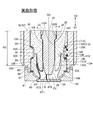
以下、本発明の実施の態様を実施形態に基づいて説明する。図1は本実施形態のプラズマジェットプラグ100の全体を示す図である。図1の軸線COより右側には、プラズマジェットプラグ100の外観が図示され、軸線COの左側には、軸線COを含む面で切断した断面図が示されている。図2は、プラズマジェットプラグ100の先端近傍を、軸線COが含まれる面で切断した断面図である。軸線COと平行な方向(図1、図2の上下方向)を軸線方向とも呼ぶ。軸線COを中心とする円の径方向を、単に「径方向」とも呼び、軸線COを中心とする円の周方向を、単に「周方向」とも呼ぶ。図1、図2における下方向を先端方向D1と呼び、上方向を後端方向D2とも呼ぶ。図1、図2における下側をプラズマジェットプラグ100の先端側と呼び、図1、図2における上側をプラズマジェットプラグ100の後端側と呼ぶ。
A. Embodiment:
A-1. Overall configuration of plasma jet plug:
Hereinafter, embodiments of the present invention will be described based on the embodiments. FIG. 1 is a view showing the whole of a plasma jet plug 100 of the present embodiment. The appearance of the plasma jet plug 100 is illustrated on the right side of the axis CO in FIG. 1, and a cross-sectional view cut along a plane including the axis CO is illustrated on the left of the axis CO. FIG. 2 is a cross-sectional view of the vicinity of the tip of the plasma jet plug 100 cut along a plane including the axis CO. The direction parallel to the axis CO (vertical direction in FIGS. 1 and 2) is also referred to as the axial direction. The radial direction of a circle centered on the axis CO is also referred to simply as the “radial direction”, and the circumferential direction of a circle centered on the axis CO is also referred to simply as the “circumferential direction”. The downward direction in FIGS. 1 and 2 is referred to as a front end direction D1, and the upward direction is also referred to as a rear end direction D2. The lower side in FIGS. 1 and 2 is referred to as the front end side of the plasma jet plug 100, and the upper side in FIGS. 1 and 2 is referred to as the rear end side of the plasma jet plug 100.

プラズマジェットプラグ100は、絶縁体10と、中心電極20と、接地電極30と、端子金具40と、主体金具50と、先端金具60と、を備える(図1)。   The plasma jet plug 100 includes an insulator 10, a center electrode 20, a ground electrode 30, a terminal fitting 40, a metal shell 50, and a tip fitting 60 (FIG. 1).

絶縁体10は、軸線方向に沿って延び、絶縁体10を貫通する軸孔12Aを有する略円筒形状を有する筒状体である。絶縁体10は、第1部材10Aと、第2部材10Bと、の2個の部材によって構成されている。第1部材10Aと第2部材10Bとは、アルミナ等を焼成して形成されている。   The insulator 10 is a cylindrical body having a substantially cylindrical shape having an axial hole 12A extending along the axial direction and penetrating the insulator 10. The insulator 10 is comprised by two members, the 1st member 10A and the 2nd member 10B. The first member 10A and the second member 10B are formed by firing alumina or the like.

第1部材10Aは、絶縁体10の大部分を占める略円筒形状を有する部材であり、上述した軸孔12Aは、第1部材10Aに形成されている。第1部材10Aは、鍔部19Aと、後端側胴部18Aと、先端側胴部17Aと、脚長部13Aと、を備えている。後端側胴部18Aは、鍔部19Aより後端側に位置し、鍔部19Aの外径より小さな外径を有している。先端側胴部17Aは、鍔部19Aより先端側に位置し、後端側胴部18Aの外径より小さな外径を有している。脚長部13Aは、先端側胴部17Aより先端側に位置し、先端側胴部17Aの外径より小さな外径を有している。先端側胴部17Aの外径は、脚長部13Aの外径より大きいので、先端側胴部17Aを、第1部材10Aの「大径部」とも呼び、脚長部13Aを、第1部材10Aの「小径部」とも呼ぶ。   The first member 10A is a member having a substantially cylindrical shape that occupies most of the insulator 10, and the above-described axial hole 12A is formed in the first member 10A. The first member 10A includes a collar 19A, a rear end side body 18A, a front end side body 17A, and a long leg 13A. The rear end side body portion 18A is located on the rear end side of the collar portion 19A, and has an outer diameter smaller than the outer diameter of the collar portion 19A. The front end side body 17A is positioned on the front end side of the collar 19A and has an outer diameter smaller than the outer diameter of the rear end side body 18A. The long leg portion 13A is located on the tip end side of the tip end side body portion 17A, and has an outer diameter smaller than the outer diameter of the tip end side body portion 17A. Since the outer diameter of the tip end side body 17A is larger than the outer diameter of the leg length 13A, the tip end side body 17A is also referred to as the "large diameter portion" of the first member 10A, and the leg length 13A is the first member 10A. Also called "small diameter part".

第2部材10Bは、軸線方向に沿って延び、第2部材10Bを貫通する貫通孔12Bを有する略円筒形状を有する部材である。第2部材10Bの軸線方向の長さは、第1部材10Aより短く、第1部材10Aの脚長部13Aより僅かに長い。第2部材10Bの貫通孔12Bの後端側には、第1部材10Aの脚長部13A(小径部)が挿入(内挿)されている。第1部材10Aと第2部材10Bの構成の詳細については、後述する。   The second member 10B is a member having a substantially cylindrical shape having a through hole 12B extending along the axial direction and penetrating the second member 10B. The axial length of the second member 10B is shorter than that of the first member 10A and slightly longer than the leg length 13A of the first member 10A. The leg long portion 13A (small diameter portion) of the first member 10A is inserted (interpolated) on the rear end side of the through hole 12B of the second member 10B. Details of the configuration of the first member 10A and the second member 10B will be described later.

主体金具50は、導電性の金属材料(例えば、低炭素鋼材)で形成され、内燃機関のエンジンヘッド(図示省略)にプラズマジェットプラグ100を固定するための略円筒形状の部材(筒状体)である。主体金具50は、軸線COに沿って貫通する挿通孔59が形成されている。主体金具50は、絶縁体10の外周に配置されている。より詳しくは、挿通孔59内に、絶縁体10のうちの第2部材10Bの後端側と、第1部材10Aの後端側胴部18Aの先端側の一部と、鍔部19Aと、先端側胴部17Aと、脚長部13Aと、が配置されている。   The metal shell 50 is formed of a conductive metal material (for example, low carbon steel material), and is a substantially cylindrical member (cylindrical body) for fixing the plasma jet plug 100 to an engine head (not shown) of an internal combustion engine. It is. The metal shell 50 is formed with an insertion hole 59 penetrating along the axis CO. The metal shell 50 is disposed on the outer periphery of the insulator 10. More specifically, the rear end side of the second member 10B of the insulator 10, a part of the front end side of the rear end side body 18A of the first member 10A, and the collar 19A in the insertion hole 59; A front end side body 17A and a leg length 13A are disposed.

主体金具50は、スパークプラグレンチが係合する六角柱形状の工具係合部51と、内燃機関に取り付けるための取付ネジ部52と、工具係合部51と取付ネジ部52との間に形成された鍔状の座部54と、を備えている(図1)。例えば、取付ネジ部52の呼び径は、M8(8mm(ミリメートル))、M10、M12、M14、M18のいずれかとされている。   The metal shell 50 is formed between a tool engagement portion 51 in the form of a hexagonal column engaged with the spark plug wrench, a mounting screw portion 52 for mounting on an internal combustion engine, and the tool engagement portion 51 and the mounting screw portion 52. And a hooked seat 54 (FIG. 1). For example, the nominal diameter of the mounting screw portion 52 is any one of M8 (8 mm (millimeter)), M10, M12, M14, and M18.

主体金具50の取付ネジ部52と座部54との間には、金属板を折り曲げて形成された環状のガスケット5が嵌挿されている(図1)。ガスケット5は、プラズマジェットプラグ100が内燃機関に取り付けられた際に、プラズマジェットプラグ100と内燃機関(エンジンヘッド)との隙間を封止する。   An annular gasket 5 formed by bending a metal plate is inserted between the mounting screw 52 and the seat 54 of the metal shell 50 (FIG. 1). The gasket 5 seals a gap between the plasma jet plug 100 and the internal combustion engine (engine head) when the plasma jet plug 100 is attached to the internal combustion engine.

主体金具50は、さらに、工具係合部51の後端側に設けられた薄肉の加締部53と、座部54と工具係合部51との間に設けられた薄肉の圧縮変形部58と、を備えている(図1)。主体金具50における工具係合部51から加締部53に至る部位の内周面と、第1部材10Aの後端側胴部18Aの外周面との間に形成される環状の領域には、環状の線パッキン6、7が配置されている。当該領域における2つの線パッキン6、7の間には、タルク(滑石)9の粉末が充填されている。   The metal shell 50 further includes a thin caulking portion 53 provided on the rear end side of the tool engagement portion 51, and a thin compression deformation portion 58 provided between the seat portion 54 and the tool engagement portion 51. And (FIG. 1). In an annular region formed between the inner peripheral surface of the portion from the tool engaging portion 51 to the caulking portion 53 in the metal shell 50 and the outer peripheral surface of the rear end side body portion 18A of the first member 10A, Annular wire packings 6, 7 are arranged. A powder of talc (talc) 9 is filled between the two line packings 6 and 7 in the area concerned.

加締部53の後端は、径方向内側に折り曲げられて、第1部材10Aの外周面に固定されている。主体金具50の圧縮変形部58は、製造時において、第1部材10Aの外周面に固定された加締部53が先端側に押圧されることにより、圧縮変形する。   The rear end of the crimped portion 53 is bent inward in the radial direction, and is fixed to the outer peripheral surface of the first member 10A. The compression deformation portion 58 of the metal shell 50 is compressed and deformed when the crimped portion 53 fixed to the outer peripheral surface of the first member 10A is pressed toward the tip end during manufacturing.

中心電極20は、軸線COに沿って延びる棒状の部材であり、第1部材10Aの軸孔12Aの先端側の部分に配置されている。中心電極20は、導電性を有し、高温での耐酸化性に優れる金属材料、例えば、ニッケル(Ni)またはNiを主成分とする合金(具体的には、NCF600、NCF601)を用いて形成されている。なお、中心電極20は、内部に埋設され、Ni又はNiを主成分として含む合金よりも熱伝導性に優れる金属、例えば、銅または銅を主成分とする合金で形成された芯材を含んでもよい。   The center electrode 20 is a rod-like member extending along the axis CO, and is disposed at a tip end side of the shaft hole 12A of the first member 10A. The center electrode 20 is formed using a metal material which has conductivity and is excellent in oxidation resistance at high temperature, such as nickel (Ni) or an alloy mainly composed of Ni (specifically, NCF 600, NCF 601). It is done. In addition, the center electrode 20 is embedded in the inside and includes a core material formed of a metal having a thermal conductivity better than Ni or an alloy containing Ni as a main component, for example, copper or an alloy containing copper as a main component Good.

先端金具60は、主体金具50の先端に接合されている。接地電極30は、先端金具60に取り付けられている。先端金具60および接地電極30は、導電性を有し、高温での耐酸化性に優れる金属材料を用いて形成されている。例えば、先端金具60には、ニッケル(Ni)またはNiを主成分とする合金(具体的には、NCF600、NCF601)が用いられる。また、接地電極30には、イリジウム(Ir)、白金(Pt)、タングステン(W)や、これらの金属を主成分とする合金などが用いられる。中心電極20、先端金具60、接地電極30を含むプラズマジェットプラグ100の先端近傍の構成の詳細については、後述する。   The end fitting 60 is joined to the end of the metal shell 50. The ground electrode 30 is attached to the end fitting 60. The end fitting 60 and the ground electrode 30 are formed using a metal material which has conductivity and is excellent in oxidation resistance at high temperature. For example, for the end fitting 60, nickel (Ni) or an alloy containing Ni as a main component (specifically, NCF 600, NCF 601) is used. Further, for the ground electrode 30, iridium (Ir), platinum (Pt), tungsten (W), an alloy mainly composed of these metals, or the like is used. Details of the configuration in the vicinity of the tip of the plasma jet plug 100 including the center electrode 20, the tip fitting 60, and the ground electrode 30 will be described later.

端子金具40は、軸線COに沿って延びる棒状の部材である。端子金具40は、導電性の金属材料(例えば、低炭素鋼)で形成され、その表面は、防食のための金属層(例えば、Ni層)がメッキなどによって形成されている。端子金具40は、軸線方向の所定位置に形成された鍔部42と、鍔部42より後端側に位置するキャップ装着部41と、鍔部42より先端側の脚部43と、を備えている。端子金具40の後端を含むキャップ装着部41は、絶縁体10の後端側に露出している。端子金具40の先端を含む脚部43は、第1部材10Aの軸孔12Aに挿入されている。キャップ装着部41には、高圧ケーブル(図示省略)が接続されたプラグキャップが装着され、火花を発生するための高電圧が印加される。   The terminal fitting 40 is a rod-like member extending along the axis CO. The terminal fitting 40 is formed of a conductive metal material (for example, low carbon steel), and on the surface thereof, a metal layer (for example, Ni layer) for corrosion prevention is formed by plating or the like. The terminal fitting 40 includes a hook portion 42 formed at a predetermined position in the axial direction, a cap mounting portion 41 positioned on the rear end side of the hook portion 42, and a leg portion 43 on the tip end side of the hook portion 42. There is. The cap mounting portion 41 including the rear end of the terminal fitting 40 is exposed to the rear end side of the insulator 10. The leg 43 including the tip of the terminal fitting 40 is inserted into the shaft hole 12A of the first member 10A. A plug cap to which a high voltage cable (not shown) is connected is mounted on the cap mounting portion 41, and a high voltage for generating a spark is applied.

第1部材10Aの軸孔12A内において、端子金具40の脚部43の先端と中心電極20の後端との間の領域は、導電性シール4によって埋められている。これにより、端子金具40と中心電極20とは、電気的に導通している。導電性シール4は、例えば、金属粒子とガラス粒子とを含む組成物で形成されている。   In the axial hole 12A of the first member 10A, a region between the front end of the leg portion 43 of the terminal fitting 40 and the rear end of the center electrode 20 is filled with the conductive seal 4. Thereby, the terminal fitting 40 and the center electrode 20 are electrically conducted. The conductive seal 4 is formed of, for example, a composition including metal particles and glass particles.

A−2. プラズマジェットプラグ100の先端近傍の構成:
上述したプラズマジェットプラグ100の先端近傍の構成について、図2の断面図を参照して、さらに、詳細に説明する。
A-2. Configuration near the tip of plasma jet plug 100:
The configuration in the vicinity of the tip of the above-described plasma jet plug 100 will be described in more detail with reference to the cross-sectional view of FIG.

第1部材10Aに形成された軸孔12Aは、後端側の大径孔121Aと、先端側の小径孔123Aと、大径孔121Aと小径孔123Aとの間に位置し、後端側から先端側に向かって縮径する縮径孔122Aと、を含んでいる。   The shaft hole 12A formed in the first member 10A is located between the large diameter hole 121A at the rear end side, the small diameter hole 123A at the front end side, the large diameter hole 121A and the small diameter hole 123A, and from the rear end side And a diameter reducing hole 122A whose diameter decreases toward the tip end side.

中心電極20は、頭部23と、鍔部24と、脚部25と、放電部26と、を備えている。鍔部24は、頭部23より先端側に位置し、頭部23より大きな外径を有する。脚部25は、鍔部24より先端側に位置する。脚部25の外径は、鍔部24より小さく、小径孔123Aの径とほぼ等しい。放電部26は、脚部25より先端側に位置し、脚部25より小さな外径を有する。また、放電部26の外径は、後端側から先端側に向かって縮径している。放電部26の先端側の面は、接地電極30との間で、火花ギャップを形成する放電面26Sである。鍔部24の先端側の面は、第1部材10Aの縮径孔122Aを形成する内周面(縮内径面)によって先端側から支持されている。頭部23および鍔部24は、導電性シール4によって後端側から支持されている。これによって、中心電極20は、脚部25および放電部26が小径孔123A内に位置するように、第1部材10Aの軸孔12A内に保持されている。   The center electrode 20 includes a head 23, a collar 24, a leg 25, and a discharger 26. The collar portion 24 is located on the tip side of the head 23 and has an outer diameter larger than that of the head 23. The legs 25 are located on the tip side of the buttocks 24. The outer diameter of the leg portion 25 is smaller than that of the collar portion 24 and substantially equal to the diameter of the small diameter hole 123A. The discharge portion 26 is located on the tip side of the leg 25 and has an outer diameter smaller than that of the leg 25. Further, the outer diameter of the discharge portion 26 is reduced in diameter from the rear end side toward the front end side. The tip side surface of the discharge portion 26 is a discharge surface 26S that forms a spark gap with the ground electrode 30. The surface on the tip end side of the collar portion 24 is supported from the tip end side by the inner peripheral surface (diameter reducing inner diameter surface) forming the diameter reducing hole 122A of the first member 10A. The head portion 23 and the collar portion 24 are supported from the rear end side by the conductive seal 4. Thus, the center electrode 20 is held in the shaft hole 12A of the first member 10A such that the leg portion 25 and the discharge portion 26 are positioned in the small diameter hole 123A.

主体金具50の挿通孔59を形成する内周面には、径方向の内側に向かって突出する棚部56が形成されている。棚部56は、棚部56の後端に位置し、後端側から先端側に向かって内径が縮径した縮内径部56Aと、棚部56の先端に位置し、後端側から先端側に向かって内径が拡径した拡内径部56Bと、を備えている。   On an inner circumferential surface forming the insertion hole 59 of the metal shell 50, a shelf portion 56 which protrudes inward in the radial direction is formed. The shelf 56 is located at the rear end of the shelf 56, and the reduced diameter portion 56A whose inner diameter is reduced from the rear end toward the tip, and at the front end of the shelf 56, from the rear end to the tip And an inner diameter portion 56B of which the inner diameter is expanded toward the end.

第1部材10Aの先端側胴部17Aは、第1後端等径部171Aと、第1後端等径部171Aより先端側の第1先端等径部173Aと、第1後端等径部171Aと第1先端等径部173Aとの間に位置する中間縮外径部172Aと、を備えている。中間縮外径部172Aの外径は、後端側から先端側に向かって縮径している。   The front end side body 17A of the first member 10A includes a first rear end equal diameter portion 171A, a first front end equal diameter portion 173A at the front end side of the first rear end equal diameter portion 171A, and a first rear end equal diameter portion And an intermediate reduced outer diameter portion 172A positioned between the first end portion 171A and the first tip end portion 173A. The outer diameter of the intermediate reduced outer diameter portion 172A decreases from the rear end side toward the front end side.

先端側胴部17Aの中間縮外径部172Aと、棚部56の縮内径部56Aと、の間には、金属製の環状の板パッキンである第1パッキン8Aが配置されている。上述したように、製造時において、第1部材10Aの外周面に固定された加締部53(図1)が先端方向D1に押圧されることにより、圧縮変形部58が圧縮変形すると、線パッキン6、7およびタルク9を介し、第1部材10Aが主体金具50の挿通孔59内で先端方向D1に押圧される。この結果、第1部材10Aは、第1パッキン8Aを介して、主体金具50の棚部56の後端側の縮内径部56Aに接触する。これによって、第1部材10Aの外周面と、主体金具50の内周面との間は、第1パッキン8Aによって封止され、キャビティCV内の高温のガスが、主体金具50と第1部材10Aとの隙間から外部に漏れることが防止される。また、金属製の第1パッキン8Aは、熱伝導率が、絶縁体10(第1部材10Aや第2部材10B)より高く、後述するように、絶縁体10の熱を主体金具50に逃がす役割を果たす。なお、第1パッキン8Aの軸線方向の位置は、主体金具50の取付ネジ部52において、外周面にネジが形成されている軸線方向の範囲RG内である。   A first packing 8A, which is an annular sheet packing made of metal, is disposed between the intermediate reduced outer diameter portion 172A of the front end side body 17A and the reduced diameter portion 56A of the shelf 56. As described above, when the compression deformation portion 58 is compressed and deformed by pressing the caulking portion 53 (FIG. 1) fixed to the outer peripheral surface of the first member 10A in the tip direction D1 at the time of manufacturing The first member 10A is pressed in the front end direction D1 in the insertion hole 59 of the metal shell 50 via the sixth and seventh and talc 9. As a result, the first member 10A contacts the reduced-diameter portion 56A on the rear end side of the shelf 56 of the metal shell 50 via the first packing 8A. Thereby, the space between the outer peripheral surface of the first member 10A and the inner peripheral surface of the metal shell 50 is sealed by the first packing 8A, and the high temperature gas in the cavity CV is the metal shell 50 and the first member 10A. Leakage to the outside from the gap between the In addition, the first packing 8A made of metal has a thermal conductivity higher than that of the insulator 10 (the first member 10A and the second member 10B), and plays a role of dissipating the heat of the insulator 10 to the metal shell 50 as described later. Play. The position of the first packing 8A in the axial direction is within the axial range RG in which a screw is formed on the outer peripheral surface of the mounting screw portion 52 of the metal shell 50.

第1部材10Aの脚長部13Aは、第1部材10Aの最も先端側の部分であり、内部には、上述した小径孔123Aが形成されている。脚長部13Aは、等径の後端部131Aと、後端部131Aより先端側に位置し、後端側から先端側に向かって外径が縮径する先端部132Aと、を備えている。第1部材10Aの先端、すなわち、脚長部13Aの先端部132Aの先端は、中心電極20の放電面26Sより後端側に位置している。   The leg long portion 13A of the first member 10A is the most distal end portion of the first member 10A, and the above-described small diameter hole 123A is formed inside. The leg length portion 13A includes a rear end portion 131A of equal diameter, and a front end portion 132A located on the front end side with respect to the rear end portion 131A and having an outer diameter reduced from the rear end side toward the front end side. The front end of the first member 10A, that is, the front end of the front end portion 132A of the leg length portion 13A is located on the rear end side of the discharge surface 26S of the center electrode 20.

第2部材10Bの内部には、上述した貫通孔12Bが形成されている。貫通孔12Bには、上述したように、第1部材10Aの脚長部13Aが内挿されている。第2部材10Bは、第2後端等径部13Bと、第2後端等径部13Bより先端側の第2先端等径部15Bと、第2後端等径部13Bと第2先端等径部15Bとの間に位置する中間拡外径部14Bと、第2先端等径部15Bより先端側の先端縮径部16Bと、を備えている。第2先端等径部15Bの外径は、第2後端等径部13Bの外径より大きい。中間拡外径部14Bの外径は、後端側から先端側に向かって拡径している。先端縮径部16Bでは、外径および内径が、後端側から先端側に向かって縮径している。第2部材10Bの先端(先端縮径部16Bの先端)は、中心電極20の放電面26Sより先端側に位置している。   The above-described through hole 12B is formed inside the second member 10B. As described above, the leg long portion 13A of the first member 10A is inserted into the through hole 12B. The second member 10B includes a second rear end equal-diameter portion 13B, a second front-end equal-diameter portion 15B on the front end side of the second rear-end equal-diameter portion 13B, a second rear-end equal-diameter portion 13B, a second front end, etc. An intermediate outer diameter portion 14B positioned between the second portion 15B and the diameter portion 15B, and a tip reduced diameter portion 16B on the tip end side of the second tip equal diameter portion 15B are provided. The outer diameter of the second front end equal diameter portion 15B is larger than the outer diameter of the second rear end equal diameter portion 13B. The outer diameter of the middle outer diameter portion 14B is expanded from the rear end side toward the front end side. The outer diameter and the inner diameter of the fore-end reduced diameter portion 16B decrease from the rear end side toward the fore end side. The tip of the second member 10B (the tip of the tip reduced diameter portion 16B) is located on the tip side of the discharge surface 26S of the center electrode 20.

先端金具60は、軸線COが通る部分に開口63を有する略円環形状を有しており、外縁部61と、内縁部62と、を備えている。外縁部61の後端には、後端側に延出した延出部64が形成されている。延出部64は、主体金具50の先端部50Sに、嵌合されている。先端金具60の延出部64と、主体金具50の先端部50Sとは、レーザ溶接によって接合されている。これによって、先端金具60は、主体金具50の先端側に固定されている。このために、図2に示すように、延出部64と先端部50Sとを跨ぐ溶接部WDが形成されている。内縁部62は、主体金具50の内周面より径方向の内側に延出しており、先端縮径部16Bの先端側の一部を覆っている。   The end fitting 60 has a substantially annular shape having an opening 63 at a portion through which the axis CO passes, and includes an outer edge portion 61 and an inner edge portion 62. At the rear end of the outer edge portion 61, an extension 64 extending to the rear end is formed. The extension portion 64 is fitted to the end portion 50S of the metal shell 50. The extension portion 64 of the end fitting 60 and the end portion 50S of the metal shell 50 are joined by laser welding. Thus, the end fitting 60 is fixed to the end side of the metal shell 50. For this purpose, as shown in FIG. 2, a welded portion WD is formed across the extension portion 64 and the distal end portion 50S. The inner edge portion 62 extends inward in the radial direction from the inner circumferential surface of the metal shell 50, and covers a part of the tip side of the tip reduced diameter portion 16B.

第2部材10Bの中間拡外径部14Bと、主体金具50の棚部56の拡内径部56Bと、の間には、金属製の環状の板パッキンである第2パッキン8Bが配置されている。また、先端金具60の外縁部61と、第2部材10Bの第2先端等径部15Bと、の間には、環状の板パッキンである第3パッキン8Cが配置されている。製造時において、先端金具60は、第3パッキン8Cを介して、第2部材10Bを後端方向D2に押圧した状態で、主体金具50の先端部50Sに接合される。このように、先端金具60は、第3パッキン8Cを介して、第2部材10Bを先端側から後端側に向かって支持している。この結果、第2部材10Bは、第2パッキン8Bを介して、主体金具50の棚部56の先端側の拡内径部56Bに接触する。これによって、第2部材10Bの外周面と、主体金具50の内周面との間は、第2パッキン8Bによって封止され、キャビティCV内の高温のガスが、主体金具50と第2部材10Bとの隙間から外部に漏れることが防止される。また、金属製の第2パッキン8Bは、熱伝導率が、絶縁体10(第1部材10Aや第2部材10B)より高く、第1パッキン8Aと同様に、絶縁体10の熱を主体金具50に逃がす役割を果たす。なお、第2パッキン8Bの軸線方向の位置は、第1パッキン8Aと同様に、取付ネジ部52において外周面にネジが形成されている軸線方向の範囲RG内である。   A second packing 8B, which is an annular plate packing made of metal, is disposed between the middle outer diameter portion 14B of the second member 10B and the inner diameter portion 56B of the shelf 56 of the metal shell 50. . A third packing 8C, which is an annular sheet packing, is disposed between the outer edge portion 61 of the end fitting 60 and the second end equal-diameter portion 15B of the second member 10B. At the time of manufacture, the tip end fitting 60 is joined to the tip end portion 50S of the metal shell 50 with the second member 10B pressed in the rear end direction D2 via the third packing 8C. As described above, the end fitting 60 supports the second member 10B from the end side toward the rear end side via the third packing 8C. As a result, the second member 10B is in contact with the inner diameter portion 56B on the tip side of the shelf 56 of the metal shell 50 via the second packing 8B. Thereby, the space between the outer peripheral surface of the second member 10B and the inner peripheral surface of the metal shell 50 is sealed by the second packing 8B, and the high temperature gas in the cavity CV is the metal shell 50 and the second member 10B. Leakage to the outside from the gap between the Further, the second packing 8B made of metal has a thermal conductivity higher than that of the insulator 10 (the first member 10A and the second member 10B), and, like the first packing 8A, the heat of the insulator 10 Play a role in The position of the second packing 8B in the axial direction is within an axial range RG in which a screw is formed on the outer peripheral surface of the mounting screw portion 52, as in the case of the first packing 8A.

接地電極30は、略円径の板部材であり、第2部材10Bの貫通孔12Bの先端側を覆っている。接地電極30の軸線COと交差する部分には、連通孔31(以下、オリフィス31とも呼ぶ)が形成されている。接地電極30の外縁部分は、先端金具60の内縁部62の径方向内側の端に、例えば、レーザ溶接によって接合されている。接地電極30には、オリフィス31が形成されているので、接地電極30をオリフィス電極とも呼ぶ。   The ground electrode 30 is a plate member having a substantially circular diameter, and covers the tip end side of the through hole 12B of the second member 10B. A communication hole 31 (hereinafter also referred to as an orifice 31) is formed in a portion intersecting the axis CO of the ground electrode 30. The outer edge portion of the ground electrode 30 is joined to the radially inner end of the inner edge portion 62 of the end fitting 60, for example, by laser welding. Since the orifice 31 is formed in the ground electrode 30, the ground electrode 30 is also referred to as an orifice electrode.

脚長部13Aの先端部分と、第2部材10Bの先端部分と、中心電極20の表面と、接地電極30の内面(後端側の面)と、によって、キャビティCVが形成されている。具体的には、例えば、脚長部13Aの先端部132Aの内周面および外周面は、キャビティCVの一部を形成している。また、例えば、先端縮径部16Bおよび第2先端等径部15Bの内周面は、キャビティCVの一部を形成している。また、中心電極20の放電面26Sおよび放電部26の外周面は、キャビティCVの一部を形成している。放電面26Sと接地電極30との間の火花ギャップは、キャビティCV内に位置している。   A cavity CV is formed by the tip end portion of the leg long portion 13A, the tip end portion of the second member 10B, the surface of the center electrode 20, and the inner surface (surface on the rear end side) of the ground electrode 30. Specifically, for example, the inner peripheral surface and the outer peripheral surface of the tip end portion 132A of the leg long portion 13A form a part of the cavity CV. Also, for example, the inner peripheral surfaces of the tip reduced diameter portion 16B and the second tip equal diameter portion 15B form a part of the cavity CV. Further, the discharge surface 26S of the center electrode 20 and the outer peripheral surface of the discharge portion 26 form a part of the cavity CV. The spark gap between the discharge surface 26S and the ground electrode 30 is located in the cavity CV.

A−3.プラズマジェットプラグ100の動作:
図3は、点火装置500の概略構成を示すブロック図である。プラズマジェットプラグ100は、図3に一例を示す点火装置500に接続され、点火装置500から電力の供給を受けることにより、内燃機関の燃焼室内の混合気への点火を行う。
A-3. Operation of Plasma Jet Plug 100:
FIG. 3 is a block diagram showing a schematic configuration of the ignition device 500. As shown in FIG. The plasma jet plug 100 is connected to an igniter 500 shown in an example in FIG. 3, and ignites the mixture in the combustion chamber of the internal combustion engine by receiving power supply from the igniter 500.

点火装置500は、例えば、自動車のECU(電子制御回路)からの指示に従ってプラズマジェットプラグ100に電力を供給する。点火装置500は、火花放電回路部540、プラズマ放電回路部560、制御回路部530、550、および逆流防止用の2つのダイオード545、565が設けられている。   The ignition device 500 supplies power to the plasma jet plug 100, for example, in accordance with an instruction from an ECU (Electronic Control Circuit) of a vehicle. The ignition device 500 is provided with a spark discharge circuit unit 540, a plasma discharge circuit unit 560, control circuit units 530 and 550, and two diodes 545 and 565 for backflow prevention.

火花放電回路部540は、プラズマジェットプラグ100の中心電極20と接地電極30の火花ギャップに、高電圧を印加することで絶縁破壊させて火花放電を生じさせる、いわゆるトリガー放電を行うための電源回路である。火花放電回路部540は、ECUに接続された制御回路部530によって制御される。火花放電回路部540は、ダイオード545を介し、電力供給先となるプラズマジェットプラグ100の中心電極20に電気的に接続されている。   The spark discharge circuit unit 540 is a power supply circuit for performing so-called trigger discharge, which causes a dielectric breakdown by applying a high voltage to the spark gap between the center electrode 20 and the ground electrode 30 of the plasma jet plug 100. It is. The spark discharge circuit unit 540 is controlled by a control circuit unit 530 connected to the ECU. The spark discharge circuit unit 540 is electrically connected to the center electrode 20 of the plasma jet plug 100 as a power supply destination via the diode 545.

また、プラズマ放電回路部560は、火花放電回路部540によって行われるトリガー放電により絶縁破壊が生じた火花ギャップに高エネルギーを供給するための電源回路である。プラズマ放電回路部560は、上記同様、ECUに接続された制御回路部550によって制御される。プラズマ放電回路部560も同様に、逆流防止用のダイオード565を介し、プラズマジェットプラグ100の中心電極20に接続されている。なお、プラズマジェットプラグ100の接地電極30は、主体金具50を介し、接地されている。   Further, the plasma discharge circuit unit 560 is a power supply circuit for supplying high energy to the spark gap in which the dielectric breakdown occurs due to the trigger discharge performed by the spark discharge circuit unit 540. The plasma discharge circuit unit 560 is controlled by the control circuit unit 550 connected to the ECU as described above. Similarly, the plasma discharge circuit unit 560 is also connected to the center electrode 20 of the plasma jet plug 100 via a diode 565 for backflow prevention. The ground electrode 30 of the plasma jet plug 100 is grounded via the metal shell 50.

プラズマ放電回路部560は、電気エネルギーを蓄えておくコンデンサ562と、コンデンサ562を充電するための高電圧発生回路561と、を備えている。コンデンサ562は、一端が接地され、他端が、高電圧発生回路561と、上記ダイオード565を介して中心電極20に接続されている。ここで、1回のプラズマ噴出を行うため、火花ギャップに供給されるエネルギー量EG(単位は、mJ)は、トリガー放電によるエネルギーの供給量と、コンデンサ562からのエネルギーの供給量との和である。コンデンサ562の静電容量は、エネルギー量EGが、規定量となるように調整されている。なお、プラズマジェットプラグ100は、例えば、プラズマ放電回路部560を備えていないタイプの点火装置、すなわち、トリガー放電によるエネルギーのみを供給するタイプの点火装置でも駆動することができるが、図3に示すような点火装置500を用いることによって、より高エネルギーのプラズマを生成することができる。   The plasma discharge circuit unit 560 includes a capacitor 562 for storing electrical energy and a high voltage generation circuit 561 for charging the capacitor 562. One end of the capacitor 562 is grounded, and the other end is connected to the center electrode 20 via the high voltage generation circuit 561 and the diode 565. Here, in order to perform plasma ejection once, the amount of energy EG (unit: mJ) supplied to the spark gap is the sum of the amount of energy supplied by the trigger discharge and the amount of energy supplied from the capacitor 562 is there. The capacitance of the capacitor 562 is adjusted so that the energy amount EG becomes a prescribed amount. The plasma jet plug 100 can also be driven by, for example, an ignition device of a type not provided with the plasma discharge circuit unit 560, that is, an ignition device of a type of supplying only energy by trigger discharge, as shown in FIG. By using such an igniter 500, a higher energy plasma can be generated.

点火装置500によって高電圧が供給されることによって、プラズマジェットプラグ100の火花ギャップに火花放電が生じると、点火装置500から供給される火花放電のエネルギーによって、図2に示すキャビティCV内の気体が励起されて、キャビティCV内にプラズマが形成される。キャビティCV内に形成されたプラズマが膨張し、キャビティCV内の圧力が高まると、キャビティCV内のプラズマは、火柱状に、接地電極30に形成されたオリフィス31から噴出される。噴出された火柱状のプラズマをプラズマとも呼ぶ。噴出されたプラズマによって、内燃機関の燃焼室内の混合気が着火される。   When spark discharge occurs in the spark gap of plasma jet plug 100 by the high voltage supplied by igniter 500, the energy of the spark discharge supplied from igniter 500 causes the gas in cavity CV shown in FIG. It is excited to form a plasma in the cavity CV. When the plasma formed in the cavity CV expands and the pressure in the cavity CV increases, the plasma in the cavity CV is ejected from the orifice 31 formed in the ground electrode 30 in a fire column. The ejected flame plasma is also called plasma. The mixture in the combustion chamber of the internal combustion engine is ignited by the ejected plasma.

以上説明した本実施形態のプラズマジェットプラグ100によれば、絶縁体10は、第1部材10Aと第2部材10Bとを備え、第1部材10Aの先端部分と、第2部材10Bの先端部分と、中心電極20の表面と、接地電極30(オリフィス電極)の内面と、によってキャビティが形成される。この結果、キャビティCVを形成する絶縁体10の表面の形状を複雑化することができる。このために、キャビティCVの容量を過度に大きくすることなく、絶縁体10の表面に沿って火花が放電する経路(以下、沿面経路)を長くすることができる。この結果、プラズマの噴出量を低下させることなく、沿面放電の発生を抑制できるので、プラズマジェットプラグ100の耐久性能と着火性能とを両立することができる。   According to the plasma jet plug 100 of the present embodiment described above, the insulator 10 includes the first member 10A and the second member 10B, and the tip portion of the first member 10A and the tip portion of the second member 10B A cavity is formed by the surface of the center electrode 20 and the inner surface of the ground electrode 30 (orifice electrode). As a result, the shape of the surface of the insulator 10 forming the cavity CV can be complicated. For this reason, it is possible to lengthen a path (hereinafter, creeping path) along which the spark is discharged along the surface of the insulator 10 without excessively increasing the capacity of the cavity CV. As a result, since the generation of the creeping discharge can be suppressed without reducing the ejection amount of plasma, both the durability performance and the ignition performance of the plasma jet plug 100 can be achieved.

プラズマジェットプラグ100の中心電極20と接地電極30との間で生じる火花放電の放電経路には、気中経路RT1と、沿面経路RT2と、の2種類の経路が考えられる。図2に示すように、気中経路RT1は、中心電極20から接地電極30までの間の空間を通る放電経路である。図2に示すように、沿面経路RT2は、絶縁体10(第1部材10Aおよび第2部材10B)の表面に沿った経路である。例えば、図2の沿面経路RT2は、先端部132Aの表面を通り、第2部材10B(第2先端等径部15Bおよび先端縮径部16B)の内周面を通り、接地電極30に至る経路である。   As a discharge path of the spark discharge generated between the center electrode 20 and the ground electrode 30 of the plasma jet plug 100, two types of paths, an air path RT1 and a surface path RT2 can be considered. As shown in FIG. 2, the air route RT <b> 1 is a discharge route passing through a space from the center electrode 20 to the ground electrode 30. As shown in FIG. 2, the surface route RT2 is a route along the surface of the insulator 10 (the first member 10A and the second member 10B). For example, the surface route RT2 in FIG. 2 passes through the surface of the tip portion 132A, passes through the inner circumferential surface of the second member 10B (the second tip equal diameter portion 15B and the tip reduced diameter portion 16B), and reaches the ground electrode 30. It is.

気中経路のみを通る火花放電を気中放電とも呼ぶ。沿面経路を含む経路を通る火花放電を沿面放電とも呼ぶ。沿面放電よりも気中放電が好ましい。沿面放電が発生すると、火花のエネルギーによって、絶縁体10が損傷を受けるからである。例えば、絶縁体10に傷や、チャンネリングと呼ばれる溝状の削れなどが発生し得る。この結果、プラズマジェットプラグ100の耐久性能が低下し得る。   Spark discharge that passes only through the air path is also called air discharge. A spark discharge passing through a path including a creeping path is also called a creeping discharge. Air discharge is preferable to creeping discharge. When a creeping discharge occurs, the energy of the spark damages the insulator 10. For example, a scratch, groove-like scraping called channeling, or the like may occur in the insulator 10. As a result, the durability of the plasma jet plug 100 may be reduced.

また、オリフィス31から噴出されるプラズマの噴出量が低下すると、燃焼室内の混合気に着火するためのエネルギーが低下するために、プラズマジェットプラグ100の着火性能が低下する。プラズマの噴出量の低下は、例えば、キャビティCVの容積が過度に大きい場合に引き起こされる。   In addition, when the ejection amount of the plasma ejected from the orifice 31 decreases, the energy for igniting the mixture in the combustion chamber decreases, so the ignition performance of the plasma jet plug 100 decreases. The decrease in the amount of ejected plasma is caused, for example, when the volume of the cavity CV is excessively large.

例えば、第2先端等径部15Bや先端縮径部16Bの径方向の内側に、先端部132Aが存在するような絶縁体10の先端部分の形状を、2個の部材を接合することなく、1個の部材で作製することは困難である。一般的に、絶縁体を形成するセラミックスは、例えば、鉄などの金属と比較して、延性が低く、脆性が高い。このために、絶縁体を形成するセラミックスは、例えば、鉄などの金属と比較して、塑性加工や切削加工の加工性が低いためである。本実施形態の絶縁体10は、別々に作製された第1部材10Aと第2部材10Bとを接合することによって作製されているので、キャビティCVの一部を形成する先端部分の形状を複雑にすることができる。   For example, without joining two members, the shape of the tip portion of the insulator 10 in which the tip portion 132A exists inside in the radial direction of the second tip uniform diameter portion 15B and the tip reduced diameter portion 16B. It is difficult to make one piece. In general, ceramics forming an insulator have low ductility and high brittleness, for example, as compared to metals such as iron. For this reason, it is because the ceramics which form an insulator have the low workability of plastic processing or cutting compared with metals, such as iron, for example. Since the insulator 10 of the present embodiment is manufactured by joining the first member 10A and the second member 10B which are separately manufactured, the shape of the tip portion forming a part of the cavity CV is complicated. can do.

この結果、本実施形態では、キャビティCVの形状を複雑にできるので、キャビティCVの形状が単純である場合と比較して、キャビティCVの容積を大きくすることなく、沿面経路RT2の経路長を長くすることができる。したがって、プラズマの噴出量を低下させることなく、沿面放電の発生を抑制して、プラズマジェットプラグ100の耐久性能と着火性能とを両立することができる。   As a result, in the present embodiment, since the shape of the cavity CV can be complicated, compared with the case where the shape of the cavity CV is simple, the path length of the surface route RT2 is increased without increasing the volume of the cavity CV. can do. Therefore, the generation of the creeping discharge can be suppressed and the durability and the ignition performance of the plasma jet plug 100 can be compatible with each other without reducing the ejection amount of plasma.

さらに、本実施形態では、第1パッキン8Aは、第1部材10Aの外面(具体的には、中間縮外径部172Aの縮外径面)と接触するとともに、主体金具50の内面(具体的には、縮内径部56Aの縮内径面)と接触している。また、第2パッキン8Bは、第2部材10Bの外面(具体的には、中間拡外径部14Bの拡外径面)と接触するとともに、主体金具50の内面(具体的には、拡内径部56Bの拡内径面)と接触している。換言すれば、第1部材10Aは、第1パッキン8Aを介して、主体金具50と接触しているとともに、第2部材10Bは、第2パッキン8Bを介して、主体金具50と接触している。そして、第1パッキン8Aの軸線方向の位置は、主体金具50においてネジが形成されている軸線方向の範囲RG内である。この結果、絶縁体10の熱引き性能を向上することができる。この結果、プレイグニッションの発生を抑制することができる。以上のように、本実施形態のプラズマジェットプラグは、着火性能と耐久性能と熱引き性能との全てを満たすことができる。   Furthermore, in the present embodiment, the first packing 8A is in contact with the outer surface of the first member 10A (specifically, the reduced outer diameter surface of the intermediate reduced outer diameter portion 172A), and the inner surface of the metal shell 50 (specifically Contact with the reduced diameter surface of the reduced diameter portion 56A. The second packing 8B is in contact with the outer surface of the second member 10B (specifically, the outer diameter surface of the intermediate outer diameter portion 14B), and the inner surface (specifically, the inner diameter of the metal shell 50). Contact with the inner diameter surface of the portion 56B). In other words, the first member 10A is in contact with the metal shell 50 via the first packing 8A, and the second member 10B is in contact with the metal shell 50 via the second packing 8B. . The axial position of the first packing 8A is within the axial range RG in which a screw is formed in the metal shell 50. As a result, the heat transfer performance of the insulator 10 can be improved. As a result, the occurrence of pre-ignition can be suppressed. As described above, the plasma jet plug of the present embodiment can satisfy all of the ignition performance, the durability performance, and the heat transfer performance.

本実施形態では、キャビティCV内に、燃焼ガスや火花放電、プラズマ生成によって、第1部材10Aの先端(先端部132Aの先端)近傍や、第2部材10Bの先端(先端縮径部16Bの先端)近傍が加熱される。第1部材10Aの先端の熱は、図2に矢印AR1で示すように、第1パッキン8Aを介して、主体金具50に伝えられる。また、第2部材10Bの先端の熱は、図2に矢印AR2で示すように、第2パッキン8Bを介して、主体金具50に伝えられる。また、第1パッキン8Aの軸線方向の位置は、ネジが形成されている軸線方向の範囲RG(図2)内であるので、第1パッキン8Aを介して、第1部材10Aから主体金具50へと伝えられた熱は、ネジを介して、内燃機関の外壁(例えば、エンジンヘッド)へと伝えられ易くなる。以上より、第1部材10Aおよび第2部材10Bの先端近傍の熱を主体金具50に効率的に逃がすことができ、ひいては、熱をエンジンヘッドに効率的に逃がすことができる。この結果、絶縁体10の熱引き性能が向上することができる。   In the present embodiment, the vicinity of the tip of the first member 10A (tip of the tip portion 132A) or the tip of the tip of the second member 10B (tip of the tip reduced diameter portion 16B) in the cavity CV by combustion gas or spark discharge or plasma generation. ) The neighborhood is heated. The heat of the tip of the first member 10A is transmitted to the metallic shell 50 through the first packing 8A as shown by an arrow AR1 in FIG. Further, the heat of the tip of the second member 10B is transmitted to the metallic shell 50 through the second packing 8B as shown by an arrow AR2 in FIG. Further, since the axial position of the first packing 8A is within the axial range RG (FIG. 2) in which the screw is formed, the first member 10A to the metal shell 50 via the first packing 8A. The transferred heat is easily transferred to the outer wall (for example, the engine head) of the internal combustion engine through the screw. As described above, the heat in the vicinity of the tips of the first member 10A and the second member 10B can be efficiently dissipated to the metal shell 50, and thus the heat can be dissipated efficiently to the engine head. As a result, the heat transfer performance of the insulator 10 can be improved.

図4は、比較形態のプラズマジェットプラグの先端近傍の断面図である。比較形態のプラズマジェットプラグ100は、実施形態と同様に、絶縁体は、第1部材10AXと、第2部材10BXとによって構成されている。そして、第1部材10AXは、先端側胴部17AXと脚長部13AXとを備える。第2部材10BXは、後端等径部13BXと、中間縮外径部14BXと、先端等径部15BXと、先端縮径部16BXと、を備えている。そして、第1部材10AXの脚長部13AXは、第2部材10BXの貫通孔12Xに挿入されている。そして、第2部材10BXの中間縮外径部14BXの外面と、主体金具50X(取付ネジ部52X)に形成された縮内径部56Xの内面と、の間に、パッキン8Xが挟まれている。中心電極20X、導電性シール4X、接地電極30Xの構成は、実施形態のプラズマジェットプラグ100とほぼ同様であるので、説明を省略する。   FIG. 4 is a cross-sectional view of the vicinity of the tip of the plasma jet plug of the comparative embodiment. In the plasma jet plug 100 of the comparative embodiment, as in the embodiment, the insulator is configured of the first member 10AX and the second member 10BX. The first member 10AX includes a tip end side body portion 17AX and a leg length portion 13AX. The second member 10BX is provided with a rear end equal diameter portion 13BX, an intermediate reduced outer diameter portion 14BX, a tip end equal diameter portion 15BX, and a tip reduction diameter portion 16BX. The leg length 13AX of the first member 10AX is inserted into the through hole 12X of the second member 10BX. The packing 8X is sandwiched between the outer surface of the intermediate reduced outer diameter portion 14BX of the second member 10BX and the inner surface of the reduced diameter portion 56X formed in the metal shell 50X (attachment screw portion 52X). The configurations of the center electrode 20X, the conductive seal 4X, and the ground electrode 30X are substantially the same as those of the plasma jet plug 100 according to the embodiment, and thus the description thereof is omitted.

比較形態のプラズマジェットプラグでは、第2部材10BXは、パッキン8Xを介して主体金具50と接触しているが、第1部材10AXは、パッキンを介して、主体金具50と接触していない。このために、比較形態のプラズマジェットプラグでは、第2部材10BXの先端(先端縮径部16BXの先端)の熱は、図4に矢印AR6で示すように、パッキン8Xを介して、主体金具50Xに逃がされる。さらに、比較形態では、実施形態とは異なり、第1部材10AXの先端(脚長部13AXの先端)の熱は、図4に矢印AR4、AR5で示すように、第2部材10Bに伝えられた後に、矢印AR6で示すように、パッキン8Xを介して、主体金具50Xに逃がされる。このように、比較形態では、第2部材10BXと、第1部材10AXと、の熱の両方が、パッキン8Xを介して、主体金具50Xに逃がされるために、実施形態と比較して効率良く熱を逃がすことができないことが解る。特に、第1部材10AXの熱は、矢印AR4、AR5に示すように、第1部材10AXと第2部材10BXとの境界を介して、逃がされるが、第1部材10AXと第2部材10BXとの境界は、隙間や接触抵抗が高い部位を含むために、熱伝導率が低い。このために、比較形態では、特に、第1部材10AXの熱を効率良く主体金具50に逃がすことができないために、熱引き性能が低下する。図2の実施形態では、このような不都合を解消して、プラズマジェットプラグ100の熱引き性能を向上することができ、ひいては、プレイグニッションの発生を抑制することができる。   In the plasma jet plug of the comparative embodiment, the second member 10BX is in contact with the metal shell 50 via the packing 8X, but the first member 10AX is not in contact with the metal shell 50 via the packing. For this reason, in the plasma jet plug of the comparative embodiment, the heat of the tip of the second member 10BX (the tip of the tip reduced diameter portion 16BX) passes through the packing 8X as shown by arrow AR6 in FIG. Be missed. Furthermore, in the comparative embodiment, unlike the embodiment, the heat of the tip of the first member 10AX (the tip of the leg length 13AX) is transmitted to the second member 10B as shown by arrows AR4 and AR5 in FIG. As shown by the arrow AR6, the metal shell 50X is released through the packing 8X. As described above, in the comparative embodiment, heat of both the second member 10BX and the first member 10AX is dissipated to the metal shell 50X through the packing 8X, so heat is efficiently conducted as compared with the embodiment. Understand that they can not escape. In particular, the heat of the first member 10AX is dissipated through the boundary between the first member 10AX and the second member 10BX as shown by arrows AR4 and AR5, but the heat of the first member 10AX and the second member 10BX The boundary has a low thermal conductivity because it includes a gap and a portion with high contact resistance. For this reason, in the comparative embodiment, in particular, the heat of the first member 10AX can not be efficiently dissipated to the metal shell 50, so the heat drawing performance is reduced. In the embodiment of FIG. 2, such a disadvantage can be eliminated, and the heat drawing performance of the plasma jet plug 100 can be improved, and in turn, the occurrence of pre-ignition can be suppressed.

さらに、本実施形態のプラズマジェットプラグ100は、主体金具50の先端側に固定されるとともに、第2部材10Bを先端側から後端側に向かって支持する先端金具60を備えている。この結果、先端金具60によって、第2部材10Bを先端側から後端側に向かって支持できるので、第1部材10Aを、第1パッキン8Aを介して、主体金具50と接触させるとともに、第2部材10Bを、第2パッキン8Bを介して、主体金具50と接触させる構造を容易に実現できる。   Furthermore, the plasma jet plug 100 of the present embodiment is provided with a tip fitting 60 that is fixed to the tip end side of the metal shell 50 and supports the second member 10B from the tip end toward the rear end side. As a result, since the second member 10B can be supported from the front end side toward the rear end side by the front end fitting 60, the first member 10A is brought into contact with the metal shell 50 via the first packing 8A. A structure in which the member 10B is in contact with the metal shell 50 via the second packing 8B can be easily realized.

さらに、本実施形態では、第2パッキン8Bの軸線方向の位置は、第1パッキン8Aと同様に、主体金具50の外周面にネジが形成されている軸線方向の範囲RG内である(図2)。この結果、第2パッキン8Bを介して、第2部材10Bから主体金具50へと伝えられた熱は、ネジを介して、内燃機関の外壁(例えば、エンジンヘッド)へと伝えられ易くなる。この結果、第2部材10Bの熱引き性能を、さらに、向上することができる。   Furthermore, in the present embodiment, the position of the second packing 8B in the axial direction is within the axial range RG in which a screw is formed on the outer peripheral surface of the metal shell 50 as in the first packing 8A (FIG. 2) ). As a result, the heat transmitted from the second member 10B to the metallic shell 50 through the second packing 8B is easily transmitted to the outer wall (for example, the engine head) of the internal combustion engine through the screw. As a result, the heat transfer performance of the second member 10B can be further improved.

さらに、本実施形態では、主体金具50は、内周面から径方向の内側に向かって突出する棚部56を備えている。そして、第1部材10Aは、第1パッキン8Aを介して、棚部56の後端側に接触し、第2部材10Bは、第2パッキン8Bを介して、棚部56の先端側に接触している。この結果、第1部材10Aを、第1パッキン8Aを介して、主体金具50と接触させるとともに、第2部材10Bを、第2パッキン8Bを介して、主体金具50と接触させる構造を容易に実現できる。   Furthermore, in the present embodiment, the metal shell 50 is provided with the shelf portion 56 which protrudes inward in the radial direction from the inner peripheral surface. Then, the first member 10A contacts the rear end side of the shelf 56 via the first packing 8A, and the second member 10B contacts the front end side of the shelf 56 via the second packing 8B. ing. As a result, a structure in which the first member 10A is brought into contact with the metallic shell 50 via the first packing 8A and the second member 10B is brought in contact with the metallic shell 50 via the second packing 8B is easily realized. it can.

B.変形例
例えば、図2に示すプラズマジェットプラグ100の先端部の具体的構成は、一例であり、様々な変形が可能である。
B. Modified Example For example, the specific configuration of the tip portion of the plasma jet plug 100 shown in FIG. 2 is an example, and various modifications are possible.

(1)例えば、第3パッキン8Cは、省略可能であり、先端金具60が直接に第2部材10Bと接触していても良い。第3パッキン8Cが省略されても、先端金具60によって第2部材10Bを先端側から後端側に向かって支持することによって、第2部材10Bを第2パッキン8Bを介して主体金具50に接触させることは十分に可能である。 (1) For example, the third packing 8C can be omitted, and the end fitting 60 may be in direct contact with the second member 10B. Even if the third packing 8C is omitted, the second member 10B is in contact with the metal shell 50 via the second packing 8B by supporting the second member 10B from the front end side toward the rear end side by the front end metal fitting 60 It is possible enough to

(2)先端金具60の延出部64および主体金具50の先端部50Sが省略されて、先端金具60の外縁部61の後端面と、主体金具50の先端面と、を接触させても良い。そして、先端金具60の外縁部61に対して、先端側からレーザを照射することによって、先端金具60と主体金具50とが接合されても良い。 (2) The extended portion 64 of the end fitting 60 and the end portion 50S of the metal shell 50 may be omitted, and the rear end surface of the outer edge portion 61 of the end fitting 60 may be in contact with the end surface of the metal shell 50 . Then, the distal end fitting 60 and the metal shell 50 may be joined by irradiating the outer edge portion 61 of the distal end fitting 60 with a laser from the distal end side.

(3)脚長部13Aの先端部132Aの肉厚は、より薄くても良いし、先端部132Aの外径は縮径していなくても良い。ただし、先端部132Aの肉厚は、厚いほど、過度に加熱されることを抑制できるので、よりプレイグニッションを抑制できる。また、先端部132Aの外径が縮径することによって、後端側ほど肉厚を厚くする方が、先端部132Aの熱を後端側に移動させ易いために、より熱引き性能を向上できる。 (3) The thickness of the distal end portion 132A of the leg long portion 13A may be thinner, and the outer diameter of the distal end portion 132A may not be reduced. However, as the thickness of the tip portion 132A is thicker, excessive heating can be suppressed, so pre-ignition can be further suppressed. In addition, since the heat of the tip end portion 132A can be easily moved to the back end side if the thickness is increased toward the rear end side by reducing the outer diameter of the tip end portion 132A, the heat drawing performance can be further improved. .

(4)第2パッキン8Bの軸線方向の位置は、ネジが形成されている軸線方向の範囲RGより先端側であっても良い。 (4) The axial position of the second packing 8B may be on the tip side of the axial range RG in which the screw is formed.

(5)第1部材10Aを第1パッキン8Aを介して主体金具50に接触させ、第2部材10Bを第2パッキン8Bを介して主体金具50に接触させる図2の構造は、一例であり、他の構造が採用されても良い。例えば、図示は省略するが、主体金具50の内周面に、第1棚部と、第1棚部より先端側の第2棚部を形成しても良い。この場合には、例えば、第1棚部の後端側と、第1部材10Aの中間縮外径部172Aと、の間に、第1パッキン8Aが配置されても良い。そして、第2棚部の後端側と、第2部材10Bの第2先端等径部15Bの先端面との間に、第2パッキン8Bが配置されても良い。 (5) The structure of FIG. 2 in which the first member 10A is in contact with the metal shell 50 via the first packing 8A and the second member 10B is in contact with the metal shell 50 via the second packing 8B is an example. Other structures may be employed. For example, although the illustration is omitted, a first shelf and a second shelf on the tip side of the first shelf may be formed on the inner circumferential surface of the metal shell 50. In this case, for example, the first packing 8A may be disposed between the rear end side of the first shelf portion and the intermediate reduced outer diameter portion 172A of the first member 10A. Then, the second packing 8B may be disposed between the rear end side of the second shelf and the front end surface of the second front end equal diameter portion 15B of the second member 10B.

(6)プラズマジェットプラグ100の発火部の構成としては、上記実施形態の構成に代えて、他の種々の構成を採用可能である。例えば、接地電極30には、複数個のオリフィス31が設けられても良い。また、中心電極20の放電部26の先端には、Ir、Pt、Wや、これらの金属を主成分とする合金で形成されたチップが接合されていても良い。 (6) As the configuration of the ignition unit of the plasma jet plug 100, various other configurations can be adopted instead of the configuration of the above embodiment. For example, the ground electrode 30 may be provided with a plurality of orifices 31. Further, a tip formed of Ir, Pt, W, or an alloy containing any of these metals as a main component may be joined to the tip of the discharge portion 26 of the center electrode 20.

以上、実施形態、変形例に基づき本発明について説明してきたが、上記した本発明の実施形態、変形例は、本発明の理解を容易にするためのものであり、本発明を限定するものではない。本発明は、その趣旨並びに特許請求の範囲を逸脱することなく、変更、改良され得ると共に、本発明にはその等価物が含まれる。   Although the present invention has been described above based on the embodiment and the modification, the embodiment and the modification of the present invention described above are for the purpose of facilitating the understanding of the present invention, and the present invention is not limited thereto. Absent. The present invention can be modified and improved without departing from the spirit and the scope of the claims, and the present invention includes the equivalents thereof.

4...導電性シール、5...ガスケット、6、7...線パッキン、8A...第1パッキン、8B...第2パッキン、8C...第3パッキン、9...タルク、10...絶縁体、10A...第1部材、10B...第2部材、12A...軸孔、12B...貫通孔、13A...脚長部、13B...第2後端等径部、14B...中間拡外径部、15B...第2先端等径部、16B...先端縮径部、17A...先端側胴部、18A...後端側胴部、19A...鍔部、20...中心電極、23...頭部、24...鍔部、25...脚部、26...放電部、26S...放電面、30...接地電極、31...オリフィス、40...端子金具、41...キャップ装着部、42...鍔部、43...脚部、50...主体金具、50S...先端部、51...工具係合部、52...取付ネジ部、53...加締部、54...座部、56...棚部、56A...縮内径部、56B...拡内径部、58...圧縮変形部、59...挿通孔、60...先端金具、61...外縁部、62...内縁部、63...開口、64...延出部、100...プラズマジェットプラグ、121A...大径孔、122A...縮径孔、123A...小径孔、131A...後端部、132A...先端部、171A...第1後端等径部、172A...中間縮外径部、173A...第1先端等径部、500...点火装置、530...制御回路部、540...火花放電回路部、545...ダイオード、550...制御回路部、560...プラズマ放電回路部、561...高電圧発生回路、562...コンデンサ、565...ダイオード、RG...範囲、CO...軸線、CV...キャビティ、RT1...気中経路、RT2...沿面経路   4 ... conductive seal, 5 ... gasket, 6, 7 ... wire packing, 8A ... 1st packing, 8B ... 2nd packing, 8C ... 3rd packing, 9. .. Talc, 10: insulator, 10A: first member, 10B: second member, 12A: axial hole, 12B: through hole, 13A: leg length, 13B .. Second rear-end equal-diameter portion 14B: intermediate outer diameter portion 15B: second-tip equal-diameter portion 16B: leading-end reduced diameter portion 17A: leading-end-side body portion 18A. ... Rear end side body portion 19A: collar portion 20: central electrode 23: head portion 24: collar portion 25: leg portion 26: discharge portion 26S: discharge surface, 30: ground electrode, 31: orifice, 40: terminal fitting, 41: cap mounting portion, 42: collar portion, 43: leg portion, 50 ... Main metal fitting, 50S ... Tip part, 51 ... Tool engaging part, 52 ... Mounting screw part, 53 ... Crimping part, 54 ... Seat part, 56 ... Shelf Part, 56A ... reduced diameter part 56B: inner diameter portion, 58: compression deformation portion, 59: insertion hole, 60: tip fitting, 61: outer edge portion, 62: inner edge portion, 63: opening, 64 extension part 100 plasma jet plug 121A large diameter hole 122A reduced diameter hole 123A small diameter hole 131A rear end 132A. ... Tip end portion 171A: first rear end equal diameter portion 172A: intermediate reduced outer diameter portion 173A: first tip equal diameter portion 500: ignition device 530: control circuit Unit 540 spark discharge circuit unit 545 diode 550 control circuit unit 560 plasma discharge circuit unit 561 high voltage generation circuit 562 capacitor 565 ... Diode, RG ... Range, CO ... Axis, CV ... Cavity, RT 1 ... Air path, RT 2 ... Creepage path

Claims (4)

軸線方向に延びる棒状の中心電極と、
前記軸線方向に延び、先端側に前記中心電極が配置された軸孔を有する筒状の絶縁体と、
前記絶縁体の外周に配置され、外周面にネジが形成された主体金具と、
前記主体金具に電気的に接続され、前記絶縁体の先端側に配置されたオリフィス電極と、
を備えるプラズマジェットプラグであって、
前記絶縁体は、
大径部と、前記大径部よりも小さな外径を有し前記大径部より先端側に配置された小径部と、を備え、前記軸孔を有する第1部材と、
前記軸線方向に延び、後端側に前記小径部が内挿された貫通孔を有する第2部材と、
を備え、
前記第1部材の先端部分と、前記第2部材の先端部分と、前記中心電極の表面と、前記オリフィス電極の内面と、によってキャビティが形成され、
前記プラズマジェットプラグは、さらに、
前記第1部材の外面と接触するとともに、前記主体金具の内面と接触する第1パッキンと、
前記第2部材の外面と接触するとともに、前記主体金具の内面と接触する第2パッキンと、
を備え、
前記第1パッキンの前記軸線方向の位置は、前記主体金具の外周面に前記ネジが形成されている前記軸線方向の範囲内であることを特徴とする、プラズマジェットプラグ。
An axially extending rod-shaped center electrode,
A cylindrical insulator having an axial hole which extends in the axial direction and in which the central electrode is disposed at the tip end side;
A metal shell disposed on the outer periphery of the insulator and having a screw formed on the outer peripheral surface thereof;
An orifice electrode electrically connected to the metal shell and disposed on the tip side of the insulator;
A plasma jet plug comprising
The insulator is
A first member having a large diameter portion and a small diameter portion having an outer diameter smaller than the large diameter portion and disposed on the tip end side of the large diameter portion, and having the shaft hole,
A second member extending in the axial direction and having a through hole into which the small diameter portion is inserted at the rear end side;
Equipped with
A cavity is formed by the tip portion of the first member, the tip portion of the second member, the surface of the center electrode, and the inner surface of the orifice electrode,
The plasma jet plug is further
A first packing in contact with the outer surface of the first member and in contact with the inner surface of the metal shell;
A second packing in contact with the outer surface of the second member and in contact with the inner surface of the metal shell;
Equipped with
The position of the said axial direction of a said 1st packing is in the range of the said axial direction by which the said screw is formed in the outer peripheral surface of the said metal shell, The plasma jet plug characterized by the above-mentioned.
請求項1に記載のプラズマジェットプラグであって、さらに、
前記主体金具の先端側に固定されるとともに、前記第2部材を先端側から後端側に向かって支持する先端金具を備えることを特徴とする、プラズマジェットプラグ。
The plasma jet plug according to claim 1, further comprising:
A plasma jet plug comprising: a tip fitting fixed to the tip end side of the metal shell and supporting the second member from the tip end side toward the rear end side.
請求項1または2に記載のプラズマジェットプラグであって、
前記第2パッキンの前記軸線方向の位置は、前記主体金具の外周面に前記ネジが形成されている前記軸線方向の範囲内であることを特徴とする、プラズマジェットプラグ。
The plasma jet plug according to claim 1 or 2, wherein
The position of the said axial direction of a said 2nd packing is in the range of the said axial direction by which the said screw is formed in the outer peripheral surface of the said metal shell, The plasma jet plug characterized by the above-mentioned.
請求項1〜3のいずれか一項に記載のプラズマジェットプラグであって、
前記主体金具は、内周面から径方向の内側に向かって突出する棚部を備え、
前記第1部材は、前記第1パッキンを介して、前記棚部の後端側に接触し、
前記第2部材は、前記第2パッキンを介して、前記棚部の先端側に接触する、プラズマジェットプラグ。
The plasma jet plug according to any one of claims 1 to 3, wherein
The metal shell includes a shelf projecting radially inward from an inner circumferential surface,
The first member contacts the rear end side of the shelf via the first packing,
The plasma jet plug according to claim 1, wherein the second member contacts the front end side of the shelf through the second packing.
JP2016122696A 2016-06-21 2016-06-21 Plasma jet plug Expired - Fee Related JP6548610B2 (en)

Priority Applications (1)

Application Number Priority Date Filing Date Title
JP2016122696A JP6548610B2 (en) 2016-06-21 2016-06-21 Plasma jet plug

Applications Claiming Priority (1)

Application Number Priority Date Filing Date Title
JP2016122696A JP6548610B2 (en) 2016-06-21 2016-06-21 Plasma jet plug

Publications (2)

Publication Number Publication Date
JP2017228394A JP2017228394A (en) 2017-12-28
JP6548610B2 true JP6548610B2 (en) 2019-07-24

Family

ID=60892108

Family Applications (1)

Application Number Title Priority Date Filing Date
JP2016122696A Expired - Fee Related JP6548610B2 (en) 2016-06-21 2016-06-21 Plasma jet plug

Country Status (1)

Country Link
JP (1) JP6548610B2 (en)

Families Citing this family (4)

* Cited by examiner, † Cited by third party
Publication number Priority date Publication date Assignee Title
CN111868228A (en) 2017-11-28 2020-10-30 国立研究开发法人科学技术振兴机构 Novel microalgae and use thereof
JP6678199B2 (en) * 2018-05-23 2020-04-08 日本特殊陶業株式会社 Spark plug
JP7202793B2 (en) 2018-06-27 2023-01-12 株式会社Soken Spark plug for internal combustion engine
JP7186044B2 (en) 2018-09-26 2022-12-08 株式会社Soken Spark plug for internal combustion engine

Family Cites Families (5)

* Cited by examiner, † Cited by third party
Publication number Priority date Publication date Assignee Title
US3882338A (en) * 1974-01-16 1975-05-06 Bendix Corp Igniter plug
JPS5811033Y2 (en) * 1979-09-04 1983-03-01 日産自動車株式会社 spark plug
JPS5644464A (en) * 1979-09-19 1981-04-23 Nissan Motor Co Ltd Ignition plug of internal combustion engine
JP2868685B2 (en) * 1993-04-26 1999-03-10 日本特殊陶業株式会社 Split type insulator for spark plug
JP6419109B2 (en) * 2016-06-08 2018-11-07 日本特殊陶業株式会社 Plasma jet plug

Also Published As

Publication number Publication date
JP2017228394A (en) 2017-12-28

Similar Documents

Publication Publication Date Title
US8082897B2 (en) Plasma jet ignition plug and ignition device for the same
JP5249385B2 (en) Plasma jet ignition plug
JP5167257B2 (en) Spark plug
CN101276997B (en) Plasma jet spark plug
JP6548610B2 (en) Plasma jet plug
JP2011175980A5 (en)
JP5476360B2 (en) Spark plug
JP6419109B2 (en) Plasma jet plug
WO2021111719A1 (en) Spark plug
JP6611769B2 (en) Spark plug
JP6034199B2 (en) Plasma jet ignition plug
JP5847259B2 (en) Spark plug
JP6071955B2 (en) Plasma jet plug
KR20150095852A (en) Ignition plug
JP5140718B2 (en) Plasma jet ignition plug
JP6347712B2 (en) Spark plug
US8946977B2 (en) Spark plug having fusion zone
JP6270802B2 (en) Spark plug
JP6418987B2 (en) Plasma jet plug
JP6411433B2 (en) Spark plug
JP6910992B2 (en) Igniter plug
JP6045466B2 (en) Plasma jet plug
JP5671446B2 (en) Plasma jet ignition plug

Legal Events

Date Code Title Description
A621 Written request for application examination

Free format text: JAPANESE INTERMEDIATE CODE: A621

Effective date: 20180626

A977 Report on retrieval

Free format text: JAPANESE INTERMEDIATE CODE: A971007

Effective date: 20190528

TRDD Decision of grant or rejection written
A01 Written decision to grant a patent or to grant a registration (utility model)

Free format text: JAPANESE INTERMEDIATE CODE: A01

Effective date: 20190604

A61 First payment of annual fees (during grant procedure)

Free format text: JAPANESE INTERMEDIATE CODE: A61

Effective date: 20190625

R150 Certificate of patent or registration of utility model

Ref document number: 6548610

Country of ref document: JP

Free format text: JAPANESE INTERMEDIATE CODE: R150

LAPS Cancellation because of no payment of annual fees