JP6546196B2 - Ophthalmic surgery system, method and apparatus - Google Patents
Ophthalmic surgery system, method and apparatus Download PDFInfo
- Publication number
- JP6546196B2 JP6546196B2 JP2016566199A JP2016566199A JP6546196B2 JP 6546196 B2 JP6546196 B2 JP 6546196B2 JP 2016566199 A JP2016566199 A JP 2016566199A JP 2016566199 A JP2016566199 A JP 2016566199A JP 6546196 B2 JP6546196 B2 JP 6546196B2
- Authority
- JP
- Japan
- Prior art keywords
- sterile
- surgical
- tray
- reusable
- handpiece
- Prior art date
- Legal status (The legal status is an assumption and is not a legal conclusion. Google has not performed a legal analysis and makes no representation as to the accuracy of the status listed.)
- Active
Links
- UAEPNZWRGJTJPN-UHFFFAOYSA-N CC1CCCCC1 Chemical compound CC1CCCCC1 UAEPNZWRGJTJPN-UHFFFAOYSA-N 0.000 description 1
Images


Classifications
-
- A—HUMAN NECESSITIES
- A61—MEDICAL OR VETERINARY SCIENCE; HYGIENE
- A61F—FILTERS IMPLANTABLE INTO BLOOD VESSELS; PROSTHESES; DEVICES PROVIDING PATENCY TO, OR PREVENTING COLLAPSING OF, TUBULAR STRUCTURES OF THE BODY, e.g. STENTS; ORTHOPAEDIC, NURSING OR CONTRACEPTIVE DEVICES; FOMENTATION; TREATMENT OR PROTECTION OF EYES OR EARS; BANDAGES, DRESSINGS OR ABSORBENT PADS; FIRST-AID KITS
- A61F9/00—Methods or devices for treatment of the eyes; Devices for putting-in contact lenses; Devices to correct squinting; Apparatus to guide the blind; Protective devices for the eyes, carried on the body or in the hand
- A61F9/007—Methods or devices for eye surgery
-
- A—HUMAN NECESSITIES
- A61—MEDICAL OR VETERINARY SCIENCE; HYGIENE
- A61B—DIAGNOSIS; SURGERY; IDENTIFICATION
- A61B50/00—Containers, covers, furniture or holders specially adapted for surgical or diagnostic appliances or instruments, e.g. sterile covers
- A61B50/10—Furniture specially adapted for surgical or diagnostic appliances or instruments
- A61B50/15—Mayo stands; Tables
-
- A—HUMAN NECESSITIES
- A61—MEDICAL OR VETERINARY SCIENCE; HYGIENE
- A61B—DIAGNOSIS; SURGERY; IDENTIFICATION
- A61B50/00—Containers, covers, furniture or holders specially adapted for surgical or diagnostic appliances or instruments, e.g. sterile covers
- A61B50/20—Holders specially adapted for surgical or diagnostic appliances or instruments
-
- A—HUMAN NECESSITIES
- A61—MEDICAL OR VETERINARY SCIENCE; HYGIENE
- A61B—DIAGNOSIS; SURGERY; IDENTIFICATION
- A61B50/00—Containers, covers, furniture or holders specially adapted for surgical or diagnostic appliances or instruments, e.g. sterile covers
- A61B50/30—Containers specially adapted for packaging, protecting, dispensing, collecting or disposing of surgical or diagnostic appliances or instruments
- A61B50/33—Trays
-
- A—HUMAN NECESSITIES
- A61—MEDICAL OR VETERINARY SCIENCE; HYGIENE
- A61B—DIAGNOSIS; SURGERY; IDENTIFICATION
- A61B90/00—Instruments, implements or accessories specially adapted for surgery or diagnosis and not covered by any of the groups A61B1/00 - A61B50/00, e.g. for luxation treatment or for protecting wound edges
- A61B90/50—Supports for surgical instruments, e.g. articulated arms
-
- A—HUMAN NECESSITIES
- A61—MEDICAL OR VETERINARY SCIENCE; HYGIENE
- A61L—METHODS OR APPARATUS FOR STERILISING MATERIALS OR OBJECTS IN GENERAL; DISINFECTION, STERILISATION OR DEODORISATION OF AIR; CHEMICAL ASPECTS OF BANDAGES, DRESSINGS, ABSORBENT PADS OR SURGICAL ARTICLES; MATERIALS FOR BANDAGES, DRESSINGS, ABSORBENT PADS OR SURGICAL ARTICLES
- A61L2/00—Methods or apparatus for disinfecting or sterilising materials or objects other than foodstuffs or contact lenses; Accessories therefor
- A61L2/02—Methods or apparatus for disinfecting or sterilising materials or objects other than foodstuffs or contact lenses; Accessories therefor using physical phenomena
- A61L2/08—Radiation
-
- A—HUMAN NECESSITIES
- A61—MEDICAL OR VETERINARY SCIENCE; HYGIENE
- A61L—METHODS OR APPARATUS FOR STERILISING MATERIALS OR OBJECTS IN GENERAL; DISINFECTION, STERILISATION OR DEODORISATION OF AIR; CHEMICAL ASPECTS OF BANDAGES, DRESSINGS, ABSORBENT PADS OR SURGICAL ARTICLES; MATERIALS FOR BANDAGES, DRESSINGS, ABSORBENT PADS OR SURGICAL ARTICLES
- A61L2/00—Methods or apparatus for disinfecting or sterilising materials or objects other than foodstuffs or contact lenses; Accessories therefor
- A61L2/24—Apparatus using programmed or automatic operation
-
- A—HUMAN NECESSITIES
- A61—MEDICAL OR VETERINARY SCIENCE; HYGIENE
- A61L—METHODS OR APPARATUS FOR STERILISING MATERIALS OR OBJECTS IN GENERAL; DISINFECTION, STERILISATION OR DEODORISATION OF AIR; CHEMICAL ASPECTS OF BANDAGES, DRESSINGS, ABSORBENT PADS OR SURGICAL ARTICLES; MATERIALS FOR BANDAGES, DRESSINGS, ABSORBENT PADS OR SURGICAL ARTICLES
- A61L2/00—Methods or apparatus for disinfecting or sterilising materials or objects other than foodstuffs or contact lenses; Accessories therefor
- A61L2/26—Accessories or devices or components used for biocidal treatment
-
- A—HUMAN NECESSITIES
- A61—MEDICAL OR VETERINARY SCIENCE; HYGIENE
- A61B—DIAGNOSIS; SURGERY; IDENTIFICATION
- A61B50/00—Containers, covers, furniture or holders specially adapted for surgical or diagnostic appliances or instruments, e.g. sterile covers
- A61B50/30—Containers specially adapted for packaging, protecting, dispensing, collecting or disposing of surgical or diagnostic appliances or instruments
- A61B2050/3008—Containers specially adapted for packaging, protecting, dispensing, collecting or disposing of surgical or diagnostic appliances or instruments having multiple compartments
-
- A—HUMAN NECESSITIES
- A61—MEDICAL OR VETERINARY SCIENCE; HYGIENE
- A61F—FILTERS IMPLANTABLE INTO BLOOD VESSELS; PROSTHESES; DEVICES PROVIDING PATENCY TO, OR PREVENTING COLLAPSING OF, TUBULAR STRUCTURES OF THE BODY, e.g. STENTS; ORTHOPAEDIC, NURSING OR CONTRACEPTIVE DEVICES; FOMENTATION; TREATMENT OR PROTECTION OF EYES OR EARS; BANDAGES, DRESSINGS OR ABSORBENT PADS; FIRST-AID KITS
- A61F9/00—Methods or devices for treatment of the eyes; Devices for putting-in contact lenses; Devices to correct squinting; Apparatus to guide the blind; Protective devices for the eyes, carried on the body or in the hand
- A61F9/007—Methods or devices for eye surgery
- A61F9/00736—Instruments for removal of intra-ocular material or intra-ocular injection, e.g. cataract instruments
-
- A—HUMAN NECESSITIES
- A61—MEDICAL OR VETERINARY SCIENCE; HYGIENE
- A61F—FILTERS IMPLANTABLE INTO BLOOD VESSELS; PROSTHESES; DEVICES PROVIDING PATENCY TO, OR PREVENTING COLLAPSING OF, TUBULAR STRUCTURES OF THE BODY, e.g. STENTS; ORTHOPAEDIC, NURSING OR CONTRACEPTIVE DEVICES; FOMENTATION; TREATMENT OR PROTECTION OF EYES OR EARS; BANDAGES, DRESSINGS OR ABSORBENT PADS; FIRST-AID KITS
- A61F9/00—Methods or devices for treatment of the eyes; Devices for putting-in contact lenses; Devices to correct squinting; Apparatus to guide the blind; Protective devices for the eyes, carried on the body or in the hand
- A61F9/007—Methods or devices for eye surgery
- A61F9/008—Methods or devices for eye surgery using laser
- A61F9/00821—Methods or devices for eye surgery using laser for coagulation
-
- A—HUMAN NECESSITIES
- A61—MEDICAL OR VETERINARY SCIENCE; HYGIENE
- A61L—METHODS OR APPARATUS FOR STERILISING MATERIALS OR OBJECTS IN GENERAL; DISINFECTION, STERILISATION OR DEODORISATION OF AIR; CHEMICAL ASPECTS OF BANDAGES, DRESSINGS, ABSORBENT PADS OR SURGICAL ARTICLES; MATERIALS FOR BANDAGES, DRESSINGS, ABSORBENT PADS OR SURGICAL ARTICLES
- A61L2202/00—Aspects relating to methods or apparatus for disinfecting or sterilising materials or objects
- A61L2202/10—Apparatus features
- A61L2202/14—Means for controlling sterilisation processes, data processing, presentation and storage means, e.g. sensors, controllers, programs
-
- A—HUMAN NECESSITIES
- A61—MEDICAL OR VETERINARY SCIENCE; HYGIENE
- A61L—METHODS OR APPARATUS FOR STERILISING MATERIALS OR OBJECTS IN GENERAL; DISINFECTION, STERILISATION OR DEODORISATION OF AIR; CHEMICAL ASPECTS OF BANDAGES, DRESSINGS, ABSORBENT PADS OR SURGICAL ARTICLES; MATERIALS FOR BANDAGES, DRESSINGS, ABSORBENT PADS OR SURGICAL ARTICLES
- A61L2202/00—Aspects relating to methods or apparatus for disinfecting or sterilising materials or objects
- A61L2202/10—Apparatus features
- A61L2202/16—Mobile applications, e.g. portable devices, trailers, devices mounted on vehicles
-
- A—HUMAN NECESSITIES
- A61—MEDICAL OR VETERINARY SCIENCE; HYGIENE
- A61L—METHODS OR APPARATUS FOR STERILISING MATERIALS OR OBJECTS IN GENERAL; DISINFECTION, STERILISATION OR DEODORISATION OF AIR; CHEMICAL ASPECTS OF BANDAGES, DRESSINGS, ABSORBENT PADS OR SURGICAL ARTICLES; MATERIALS FOR BANDAGES, DRESSINGS, ABSORBENT PADS OR SURGICAL ARTICLES
- A61L2202/00—Aspects relating to methods or apparatus for disinfecting or sterilising materials or objects
- A61L2202/10—Apparatus features
- A61L2202/18—Aseptic storing means
-
- A—HUMAN NECESSITIES
- A61—MEDICAL OR VETERINARY SCIENCE; HYGIENE
- A61L—METHODS OR APPARATUS FOR STERILISING MATERIALS OR OBJECTS IN GENERAL; DISINFECTION, STERILISATION OR DEODORISATION OF AIR; CHEMICAL ASPECTS OF BANDAGES, DRESSINGS, ABSORBENT PADS OR SURGICAL ARTICLES; MATERIALS FOR BANDAGES, DRESSINGS, ABSORBENT PADS OR SURGICAL ARTICLES
- A61L2202/00—Aspects relating to methods or apparatus for disinfecting or sterilising materials or objects
- A61L2202/20—Targets to be treated
- A61L2202/24—Medical instruments, e.g. endoscopes, catheters, sharps
Description
関連出願の相互参照
本出願はPCT出願であり、MULTI−USE SURGICAL TRAY SYSTEMという名称の2014年12月12日出願の米国仮特許出願第62/091,384号明細書、OPHTHALMIC SURGICAL SYSTEMS,METHODS,AND DEVICESという名称の2014年11月26日出願の米国特許出願第14/554,865号明細書、OPHTHALMIC SURGICAL SYSTEMS,METHODS,AND DEVICESという名称の2014年11月26日出願のPCT出願であるPCT/米国特許出願公開第2014/067717号明細書、およびOPHTHALMIC SURGICAL SYSTEMSという名称の2014年5月7日出願の米国仮特許出願第61/990,021号明細書に対する優先権を主張する。前述の出願のそれぞれは、その全体が参照により本明細書に援用される。
This application is a PCT application and is US Provisional Patent Application No. 62 / 091,384, filed December 12, 2014, entitled MULTI-USE SURGICAL TRAY SYSTEM, OPHTHALMIC SURGICAL SYSTEMS, METHODS, US patent application Ser. No. 14 / 554,865 filed Nov. 26, 2014 entitled AND DEVICES PCT, a PCT application filed Nov. 26, 2014, entitled OPHTHALMIC SURGICAL SYSTEMS, METHODS, AND DEVICES / US Patent Application Publication No. 2014/067717 and U.S. Provisional Patent Application filed May 7, 2014 entitled OPHTHALMIC SURGICAL SYSTEMS Claims priority to Application No. 61 / 990,021. Each of the aforementioned applications is hereby incorporated by reference in its entirety.
本開示は概して眼科手術の分野に関し、詳細には、眼科手術システム、方法および装置に関する。 The present disclosure relates generally to the field of ophthalmic surgery, and more particularly to ophthalmic surgery systems, methods and apparatus.
成人の寿命が延び、世界人口において高齢世代の割合が増え続けるにつれ、眼科の領域は今日の社会においてますます重要になっている。視力への配慮および眼球の病気または状態への処置は近年、薬理学および医療装置技術の両方の進歩から恩恵を受けている。微小手術器具および革新的な手術技法は、外科医が、到達不可能および不可侵とこれまで考えられていた目の部分を治療または交換することを可能にしている。特に、特定の処置の組(硝子体切除または白内障除去処置など)に専用の様々な機能を提供するコンソールシステムを今日外科医は利用可能であり、技術の改善および更新が定期的に行われている。往々にしてこれらのコンソールは非常に高価であり、外科医、病院または外来外科センターによる高額の設備投資を必要とする。それらはまた、システムの単回使用用の使い捨て要素のため、高額の経常費が掛かることが多く、同じく高額のメンテナンス費用が掛かることもある。競合製品との差別化を図るため、コンソールは多くの不要なまたは頻繁に使われることのない機能を組み込んでいることが多い。従って、コストが掛かることに加え、コンソールは大型で、重く、嵩高で、騒音を出し、電力消費量が多く、肥大化した機械であることが多く、それが取り扱うように設計される小さく繊細な目と明確に対照をなす。さらに、これらのシステムの欠点は、それらが外科医から距離を取って配置されることをしばしば要求することであり、この結果、システムの性能に悪影響を及ぼす一方でコストを増大する長いチューブセットおよび/またはケーブルが使用される。従って、特定の処置を実行するのに必要である主な機能を組み込んだ、より小型で、より持ち運びやすく、より内蔵型であり、より費用対効果に優れたシステムに対する必要性が存在する。 The field of ophthalmology is becoming increasingly important in today's society as the lifespan of adults increases and the percentage of older generations in the world population continues to increase. Vision awareness and treatment of ocular diseases or conditions have recently benefited from advances in both pharmacology and medical device technology. Microsurgical instruments and innovative surgical techniques allow surgeons to treat or replace parts of the eye previously thought to be unreachable and impenetrable. In particular, nowadays surgeons are able to use console systems that offer various functions dedicated to specific treatment sets (such as vitrectomy or cataract removal treatments), and technology improvements and updates are regularly performed. . Often these consoles are very expensive and require expensive capital outlays by surgeons, hospitals or outpatient surgery centers. They are also often expensive recurring expenses due to the single use disposable elements of the system, and can also be expensive maintenance costs. Consoles often incorporate many unnecessary or infrequently used functions in order to differentiate them from competing products. Thus, in addition to being costly, the console is large, heavy, bulky, noisy, power intensive, often a bloated machine, small and delicate, designed to handle it Contrast clearly with your eyes. Furthermore, the disadvantage of these systems is that they often require them to be placed at a distance from the surgeon, which results in long tube sets and / or costs that adversely affect system performance. Or a cable is used. Thus, there is a need for a smaller, more portable, more self-contained, more cost-effective system that incorporates the primary functionality needed to perform a particular procedure.
本明細書の開示は、眼科手術用システム、方法および装置を提供する。いくつかの実施形態では、手術装置またはトレイは、1つまたは複数の再利用可能な構成要素と、再利用可能な構成要素と共に使用されるように構成された1つまたは複数の使い捨て構成要素とを含む。いくつかの実施形態では、使い捨て構成要素は、単回使用後または制限された使用回数後に処分されるように構成可能である。いくつかの実施形態では、1つまたは複数の再利用可能な部分は、無菌手術環境内に存在しないように構成された非無菌構成要素を含み、一方で1つまたは複数の使い捨て構成要素は、無菌手術環境内で使用されるように構成される。いくつかの実施形態では、無菌使い捨て部分は、非無菌の再利用可能な部分を封じ込めるように、または無菌手術環境から隔絶するように構成される。いくつかの実施形態では、手持ち手術器具は、手術機能を制御するための感圧ボタンを含む。いくつかの実施形態では、感圧ボタンは、手術器具の本体の周囲に円周方向に配置され、その結果、円周周りのいずれの位置においてもまたは実質的にいずれの位置においても(または例えば全円周の約350、325、300、275、250、225、200または180度など、所定の範囲内のいずれの位置においても)ボタンに適用された外圧は、感圧ボタンによって検出される。いくつかの実施形態では、手持ち手術器具は、例えば空気圧、液圧、光学および/または同様のボタンなど、非電気的なボタンを含む。いくつかの実施形態では、眼科手術システムは、再利用可能なベースと、それに結合された使い捨ての無菌手術用トレイとを利用するように構成される。いくつかの実施形態では、いくつかの機能が使い捨てトレイ内に含まれるか、またはそれに結合され、その機能とは、例えば、流体および/またはハンドピース;ならびに例えば、再利用可能なベース内に配置されたハンドピース用の動力源(例えば、電気的、機械的、液圧的、空気圧的、光学的および/またはそれらに類するもの)などの再利用可能な構成要素である。いくつかの実施形態では、ある機能がそれを通過することを可能にする1つまたは複数の機能的インターフェースを含む特注の手術用ドレープが提供される。いくつかの実施形態では、通過するように構成される機能は、電流、光線、空気圧または流体結合、および/もしくは機械的結合または他の特徴部を含み得る。いくつかの実施形態では、眼科手術システムは、自動的に更新されるように構成されるか、またはRFIDタグ、近距離無線通信装置、メモリーカード/USB、もしくは他の記憶装置、および/またはそれらに類するものなどのタグの検出に応答するように構成される。 The disclosure herein provides systems, methods and apparatus for ophthalmic surgery. In some embodiments, the surgical device or tray comprises one or more reusable components and one or more disposable components configured for use with the reusable components. including. In some embodiments, the disposable component can be configured to be disposed of after a single use or after a limited number of uses. In some embodiments, the one or more reusable parts comprise non-sterile components configured to not be within the sterile surgical environment, while the one or more disposable components are It is configured to be used in a sterile surgical environment. In some embodiments, the sterile disposable portion is configured to contain a non-sterile recyclable portion or to isolate it from a sterile surgical environment. In some embodiments, the hand-held surgical instrument includes a pressure sensitive button to control the surgical function. In some embodiments, the pressure sensitive button is circumferentially disposed about the body of the surgical instrument so that it is at any position or substantially at any position around the circumference (or for example The external pressure applied to the button) at any position within a predetermined range, such as about 350, 325, 300, 275, 250, 225, 200 or 180 degrees of the full circumference, is detected by the pressure sensitive button. In some embodiments, the hand-held surgical instrument includes non-electrical buttons, such as, for example, pneumatic, hydraulic, optical and / or similar buttons. In some embodiments, the ophthalmic surgery system is configured to utilize a reusable base and a disposable sterile surgical tray coupled thereto. In some embodiments, some features are contained within or coupled to the disposable tray, such as, for example, fluid and / or hand pieces; and, for example, disposed within a reusable base Reusable components such as power sources for the handpiece (eg, electrical, mechanical, hydraulic, pneumatic, optical and / or the like). In some embodiments, a custom surgical drape is provided that includes one or more functional interfaces that allow a function to pass therethrough. In some embodiments, the features configured to pass may include current, light, pneumatic or fluid coupling, and / or mechanical coupling or other features. In some embodiments, the ophthalmic surgery system is configured to be updated automatically, or an RFID tag, near field communication device, memory card / USB, or other storage device, and / or the like. Configured to respond to the detection of a tag such as
いくつかの実施形態によれば、外科的処置の間、外科医が使用するための手術用装置は、外科的処置の前に開封され、かつ単回または制限された回数の外科的処置後に処分されるように構成された1つまたは複数の密封された滅菌済み手術パックを含み、1つまたは複数の密封された滅菌済み手術パックは、無菌手術器具、および外科的処置の無菌領域の一部であるように構成された上面を含む無菌手術用トレイを含み、無菌手術用トレイはさらに、再利用可能な非無菌モジュールを受け入れるようにサイズを決められかつ構成された凹部を画定する壁を含み、凹部は、再利用可能な非無菌モジュールを完全または部分的に封じ込めて再利用可能な非無菌モジュールを外科的処置の無菌領域から隔絶するように構成され、ここで無菌手術用トレイの壁は、再利用可能な非無菌モジュールの1つまたは複数の機能が凹部の外側の外科的処置の無菌領域で利用されることを可能にするように配置かつ構成された1つまたは複数のインターフェースを含む。いくつかの実施形態では、1つまたは複数のインターフェースは、再利用可能な非無菌モジュールの電子制御器が無菌手術用トレイまたは無菌手術器具と電子的に通信することを可能にするように構成された少なくとも電子通信インターフェースを含む。 According to some embodiments, the surgical device for use by the surgeon during the surgical procedure is opened prior to the surgical procedure and disposed of after a single or limited number of surgical procedures. Containing one or more sealed sterile surgical packs, one or more sealed sterile surgical packs, a sterile surgical instrument and a part of the sterile area of the surgical procedure The sterile surgical tray further includes a wall defining a recess sized and configured to receive the reusable non-sterile module, including a sterile surgical tray including an upper surface configured to be one side, The recess is configured to completely or partially contain the reusable non-sterile module to isolate the reusable non-sterile module from the sterile area of the surgical procedure, where the sterile surgical gear B) one or more arranged and configured to allow one or more functions of the reusable non-sterile module to be utilized in the aseptic area of the surgical procedure outside the recess Including the interface. In some embodiments, the one or more interfaces are configured to allow the electronic controller of the reusable non-sterile module to be in electronic communication with the sterile surgical tray or the sterile surgical instrument. At least an electronic communication interface.
いくつかの実施形態では、凹部は無菌手術用トレイの中心に配置される。いくつかの実施形態では、無菌手術用トレイは、再利用可能な非無菌モジュールを封じ込める凹部を形成するために選択的に相互に結合可能である少なくとも2つの部品を含む。いくつかの実施形態では、無菌手術用トレイは、凹部にアクセスするためのヒンジ式開口部を含む。いくつかの実施形態では、1つまたは複数のインターフェースが、再利用可能な非無菌モジュールのモータから、無菌手術用トレイに接続された流体ポンプへ回転運動を伝達するための機械的結合部を含む。いくつかの実施形態では、1つまたは複数のインターフェースは、再利用可能な非無菌モジュールの光源から無菌手術器具へ光を伝送するための光伝送結合部を含む。いくつかの実施形態では、1つまたは複数のインターフェースは、非無菌モジュールから無菌手術用トレイへ電力を送るための電気伝導性結合部を含む。いくつかの実施形態では、1つまたは複数のインターフェースは、非無菌モジュールと無菌手術用トレイまたは無菌手術器具との間で電子通信を可能にする電子通信結合部を含む。いくつかの実施形態では、再利用可能な非無菌モジュールの1つまたは複数の機能は、機械的動力を提供すること、電力を提供すること、電子的処理または制御を提供すること、レーザ源を提供すること、光源を提供すること、および情報を表示することのうちの少なくとも1つを含む。いくつかの実施形態では、無菌手術用トレイの上面は、無菌手術器具を配置するための受入構造を含む。 In some embodiments, the recess is located at the center of the sterile surgical tray. In some embodiments, the sterile surgical tray includes at least two components that can be selectively coupled together to form a recess that encloses the reusable non-sterile module. In some embodiments, the sterile surgical tray includes a hinged opening for accessing the recess. In some embodiments, the one or more interfaces include mechanical couplings for transferring rotational movement from the reusable non-sterile module motor to the fluid pump connected to the sterile surgical tray . In some embodiments, the one or more interfaces include a light transmission coupling for transmitting light from the light source of the reusable non-sterile module to the sterile surgical instrument. In some embodiments, the one or more interfaces include an electrically conductive connection for transferring power from the non-sterile module to the sterile surgical tray. In some embodiments, the one or more interfaces include an electronic communication coupling that enables electronic communication between the non-sterile module and the sterile surgical tray or sterile surgical instrument. In some embodiments, one or more functions of the reusable non-sterile module provide mechanical power, provide power, provide electronic processing or control, laser source At least one of providing, providing a light source, and displaying information. In some embodiments, the top surface of the sterile surgical tray includes a receiving structure for placing sterile surgical instruments.
いくつかの実施形態によれば、外科的処置の間、外科医が使用するための手術用装置は、外科的処置の前に開封され、かつ単回または制限された回数の外科的処置後に処分されるように構成された1つまたは複数の密封された滅菌済み手術パックを含み、1つまたは複数の密封された滅菌済み手術パックは、無菌手術器具、および外科的処置の無菌領域の一部であるように構成された上面と、再利用可能な支持構造体の上面に結合されかつ上面によって支持されるようにサイズを決められかつ構成された底面とを含む無菌手術用トレイを含み、再利用可能な支持構造体は、モータ、光源、および使用者インターフェースディスプレイのうちの少なくとも1つを含み、ここで、無菌手術用トレイは、支持構造体のモータから、無菌手術用トレイに接続された流体ポンプへ回転運動を伝達するための機械的結合部、支持構造体の光源から無菌手術器具へ光を伝送するための光伝送結合部、および透明材料であって、支持構造体の使用者インターフェースディスプレイを外科的処置の無菌領域でその透明材料を通して見ることを可能にするように配置された透明材料のうちの少なくとも1つを含む。 According to some embodiments, the surgical device for use by the surgeon during the surgical procedure is opened prior to the surgical procedure and disposed of after a single or limited number of surgical procedures. Containing one or more sealed sterile surgical packs, one or more sealed sterile surgical packs, a sterile surgical instrument and a part of the sterile area of the surgical procedure A sterile surgical tray comprising a top surface configured in some manner, and a bottom surface coupled to the top surface of the reusable support structure and sized and configured to be supported by the top surface; Possible support structures include at least one of a motor, a light source, and a user interface display, wherein the sterile surgical tray comprises a motor for the support structure, a sterile surgical tray A mechanical coupling for transmitting rotational movement to the connected fluid pump, a light transmitting coupling for transmitting light from the light source of the support structure to the sterile surgical instrument, and a transparent material, of the support structure The user interface display includes at least one of the transparent materials arranged to allow viewing through the transparent material in the sterile area of the surgical procedure.
いくつかの実施形態では、1つまたは複数の密封された滅菌済み手術パックはさらに、無菌手術用トレイの底面と、再利用可能な支持構造体の上面との間に配置されるようにサイズを決められた無菌ドレープを含む。いくつかの実施形態では、無菌ドレープは、電流が再利用可能な支持構造体から無菌手術用トレイへ流れることを可能にするように構成された伝導性インターフェースを含む。いくつかの実施形態では、再利用可能な支持構造体は非無菌である。いくつかの実施形態では、無菌手術用トレイは、折り畳まれた輸送用構成と、展開された手術時使用構成とを含む。いくつかの実施形態では、無菌手術用トレイの少なくとも一部は、折り畳まれた輸送用構成において、無菌手術器具を損傷から保護するように構成される。いくつかの実施形態では、再利用可能な支持構造体はモータを含み、1つまたは複数の密封された滅菌済み手術パックはさらに無菌ポンプモジュールを含み、および無菌ポンプモジュールは無菌手術用トレイから分離し、かつ再利用可能な支持構造体に別々に結合されかつ再利用可能な支持構造体によって支持されるように構成され、ここで、無菌ポンプモジュールは、モータからポンプモジュールの流体ポンプへ回転運動を伝達するための回転結合部を含む。いくつかの実施形態では、無菌手術用トレイの上面は、無菌手術器具を配置するための受入構造を含む。 In some embodiments, the one or more sealed sterile surgical packs are further sized to be disposed between the bottom of the sterile surgical tray and the top of the reusable support structure. Includes defined sterile drapes. In some embodiments, the sterile drape includes a conductive interface configured to allow current to flow from the reusable support structure to the sterile surgical tray. In some embodiments, the reusable support structure is non-sterile. In some embodiments, the sterile surgical tray includes a folded shipping configuration and a deployed surgical use configuration. In some embodiments, at least a portion of the sterile surgical tray is configured to protect the sterile surgical instrument from damage in the folded shipping configuration. In some embodiments, the reusable support structure includes a motor, the one or more sealed sterile surgical packs further include a sterile pump module, and the sterile pump module is separated from the sterile surgical tray And configured to be separately coupled to and supported by the reusable support structure, wherein the aseptic pump module is rotated from the motor to the fluid pump of the pump module Includes a rotational coupling for transmitting the In some embodiments, the top surface of the sterile surgical tray includes a receiving structure for placing sterile surgical instruments.
いくつかの実施形態によれば、外科的処置の間、外科医が使用するための手術用装置は、外科的処置の前に開封され、かつ単回または制限された回数の外科的処置後に処分されるように構成された1つまたは複数の密封された滅菌済み手術パックを含み、1つまたは複数の密封された滅菌済み手術パックは、無菌手術器具、および外科的処置の無菌領域の一部であるように構成された上面を含む無菌手術器具ホルダを含み、上面は無菌手術器具を配置するための受入構造を含み、無菌手術器具ホルダはさらに、再利用可能な支持構造体の第1凹部内に受け入れられるようにサイズを決められかつ構成された底面と、再利用可能な構造体の第2凹部内に受け入れられるようにサイズを決められかつ構成された無菌注入モジュールとを含み、無菌注入モジュールは、無菌領域または手術部位への流体のポンピングを可能にするために再利用可能な支持構造体のモータと結合するように構成されたポンプヘッドを含む。いくつかの実施形態では、1つまたは複数の密封された滅菌済み手術パックはさらに、無菌領域または手術部位から出る流体のポンピングを可能にするために再利用可能な支持構造体のモータと結合するように構成されたポンプヘッドを含む無菌吸引モジュールを含む(または無菌手術器具、無菌手術器具ホルダおよび/もしくは無菌注入モジュールは無菌吸引モジュールと置き換えられる)。いくつかの実施形態では、無菌注入モジュールおよび/または無菌吸引モジュールは、再利用可能な支持構造体のモータと結合するように構成されたポンプヘッドの代わりに、モータに結合されたポンプヘッドを含む。 According to some embodiments, the surgical device for use by the surgeon during the surgical procedure is opened prior to the surgical procedure and disposed of after a single or limited number of surgical procedures. Containing one or more sealed sterile surgical packs, one or more sealed sterile surgical packs, a sterile surgical instrument and a part of the sterile area of the surgical procedure The sterile surgical instrument holder including the upper surface configured to have a top surface, the upper surface including the receiving structure for placing the sterile surgical instrument, the sterile surgical instrument holder further being within the first recess of the reusable support structure A sterile infusion module sized and configured to be accepted by the user, and a sterile injection module sized and configured to be received within the second recess of the reusable structure Input module includes a pump configured head to mate with the motor of the reusable support structure to allow pumping of fluid into the sterile field or surgical site. In some embodiments, one or more sealed sterile surgical packs are further coupled to the motor of the reusable support structure to allow pumping of fluid out of the sterile area or surgical site (A sterile surgical instrument, a sterile surgical instrument holder and / or a sterile infusion module are replaced with a sterile aspiration module) comprising a pump head configured as such. In some embodiments, the sterile injection module and / or the sterile suction module includes a pump head coupled to the motor instead of the pump head configured to couple with the motor of the reusable support structure. .
いくつかの実施形態では、無菌手術器具ホルダは、折り畳み構成と、展開構成とを含み、折り畳み構成は輸送時に手術器具を保護するように構成され、展開構成は外科的処置の無菌領域内で手術器具へのアクセスを可能にするように構成される。いくつかの実施形態では、1つまたは複数の密封された滅菌済み手術パックはさらに、第2の無菌手術器具を配置するための受入構造を含む第2の無菌手術器具ホルダを含み、手術器具ホルダは、輸送時に手術器具を保護するために折り畳み構成において1つに結合するように成形かつ構成される。いくつかの実施形態では、手術器具は、再利用可能な支持構造体の光源、再利用可能な支持構造体の電子制御装置、再利用可能な支持構造体の機械的駆動装置(例えば、伝達ケーブルもしくはトルクコイル、および/またはそれらに類するもの)、および再利用可能な支持構造体の空気圧または液圧駆動装置(例えば、ポンプ、圧縮源、および/またはそれらに類するもの)のうちの1つまたは複数と結合するように構成される。いくつかの実施形態では、再利用可能な支持構造体は非無菌である。いくつかの実施形態では、1つまたは複数の密封された滅菌済み手術パックはさらに、非無菌の再利用可能な支持構造体と、手術器具ホルダおよび注入モジュールのうちの少なくとも1つとの間に配置されるように構成された手術用ドレープを含む。 In some embodiments, the sterile surgical instrument holder includes a folded configuration and a deployed configuration, wherein the folded configuration is configured to protect the surgical instrument during transport, the deployed configuration operating within the sterile area of the surgical procedure Configured to allow access to the device. In some embodiments, the one or more sealed sterile surgical packs further include a second sterile surgical instrument holder including a receiving structure for placing a second sterile surgical instrument, the surgical instrument holder Are shaped and configured to bond together in a folded configuration to protect the surgical instrument during transport. In some embodiments, the surgical instrument comprises a light source of the reusable support structure, an electronic controller of the reusable support structure, a mechanical drive of the reusable support structure (e.g., a transmission cable). Or torque coil, and / or the like), and pneumatic or hydraulic drive of the reusable support structure (eg, pump, compression source, and / or the like) or Configured to combine with multiple. In some embodiments, the reusable support structure is non-sterile. In some embodiments, the one or more sealed sterile surgical packs are further disposed between the non-sterile reusable support structure and at least one of the surgical instrument holder and the infusion module A surgical drape configured to be
いくつかの実施形態によれば、外科的処置の間、外科医が使用するための手術用装置は、外科的処置の前に開封され、かつ単回または制限された回数の外科的処置後に処分されるように構成された1つまたは複数の密封された滅菌済み手術パックであって、無菌注入モジュールおよび無菌吸引モジュールの1つまたは複数を含む、1つまたは複数の密封された滅菌済み手術パックを含む、無菌注入および吸引モジュールはそれぞれ、再利用可能な支持構造体の凹部に取外し可能に受け入れられるようにサイズを決められかつ構成された壁と、外科的処置の無菌領域の一部であるように構成された少なくとも1つの外側表面とを含むハウジングと、流体を手術部位へまたは手術部位からポンピングするためのポンプと、ポンプのロータを回転させるためにポンプに結合されたモータとを含み、ここで、ハウジングはさらに、モータに動力供給するために再利用可能な支持構造体から電力を受け取るように構成された電気的インターフェースを含み、ここで無菌注入モジュールは、流体を手術部位へポンピングするように構成され、および無菌吸引モジュールは、流体を手術部位からポンピングするように構成される。 According to some embodiments, the surgical device for use by the surgeon during the surgical procedure is opened prior to the surgical procedure and disposed of after a single or limited number of surgical procedures. One or more sealed sterile surgical packs configured to perform one or more sealed sterile surgical packs including one or more of a sterile infusion module and a sterile aspiration module Each of the sterile infusion and aspiration modules, including: a wall, sized and configured to be removably received in the recess of the reusable support structure, and part of the sterile area of the surgical procedure A housing including at least one outer surface configured to rotate the pump rotor for pumping fluid to or from the surgical site; And a motor coupled to the pump, wherein the housing further includes an electrical interface configured to receive power from the reusable support structure to power the motor, The aseptic injection module is configured to pump fluid to the surgical site, and the sterile suction module is configured to pump fluid from the surgical site.
いくつかの実施形態では、1つまたは複数の密封された滅菌済み手術パックは、無菌注入モジュールおよび無菌吸引モジュールのそれぞれの少なくとも1つを含む。いくつかの実施形態では、ポンプは滅菌構成を含み、滅菌構成では最大で1つの狭窄地点がポンプのぜん動チューブに形成される。いくつかの実施形態では、ポンプは、滅菌位置から作動位置へ再配置可能な複数のローラを含み、ここで、滅菌位置において、ローラは作動位置のときよりもポンプの中心軸により近づく。いくつかの実施形態では、1つまたは複数の密封された滅菌済み手術パックはさらに、無菌手術器具と、外科的処置の無菌領域の一部であるように構成された上面を含む無菌手術器具ホルダとを含み、上面は無菌手術器具をその中にまたはその上に配置するための受入部分を含み、無菌手術器具ホルダはさらに、再利用可能な支持構造体の異なる凹部に受け入れられるようにサイズを決められかつ構成された底面を含む。いくつかの実施形態では、再利用可能な支持構造体は非無菌であり、および1つまたは複数の密封された滅菌済み手術パックはさらに、非無菌の再利用可能な支持構造体と、モジュールのうちの少なくとも1つとの間に配置されるように構成された手術用ドレープを含む。 In some embodiments, one or more sealed sterile surgical packs include at least one of each of a sterile infusion module and a sterile aspiration module. In some embodiments, the pump includes a sterile configuration, wherein at most one stenosis point is formed in the peristaltic tube of the pump. In some embodiments, the pump includes a plurality of rollers repositionable from the sterile position to the operative position, where in the sterile position the rollers are closer to the central axis of the pump than in the operative position. In some embodiments, the one or more sealed sterile surgical packs further comprises a sterile surgical instrument and a sterile surgical instrument holder including a top surface configured to be part of a sterile area of a surgical procedure And the upper surface includes a receiving portion for placing the sterile surgical instrument therein or thereon, the sterile surgical instrument holder further being sized to be received in different recesses of the reusable support structure Includes a fixed and configured bottom surface. In some embodiments, the reusable support structure is non-sterile, and the one or more sealed sterile surgical packs further comprise: a non-sterile reusable support structure; And a surgical drape configured to be disposed between at least one of the plurality.
いくつかの実施形態によれば、外科的処置用の手持ち医療器具は、人間の手によって保持されかつ操作されるように成形された外側表面を有する本体と、本体の遠位端から延びる手術ツールと、手術ツールの作動を制御するための感圧ボタンとを含み、感圧ボタンは本体の外側表面に隣接して配置された作動表面を含み、感圧ボタンはさらに圧力検出装置を含み、圧力検出装置は手術ツールの機能を制御するために信号の出力を可能にするように構成され、信号は作動表面の位置に比例する。 According to some embodiments, a hand-held medical instrument for surgical procedures comprises a body having an outer surface shaped to be held and manipulated by a human hand, and a surgical tool extending from a distal end of the body. And a pressure sensitive button for controlling the operation of the surgical tool, the pressure sensitive button including an operative surface disposed adjacent to the outer surface of the body, the pressure sensitive button further including a pressure sensing device; The detection device is configured to enable the output of a signal to control the function of the surgical tool, the signal being proportional to the position of the working surface.
いくつかの実施形態では、圧力検出装置は、作動表面の位置に基づいて抵抗を変える力感受性抵抗器を含む。いくつかの実施形態では、作動表面は本体の外面の周囲を円周方向に延在し、力感受性抵抗器の伝導性表面の周囲に少なくとも部分的に配置される。いくつかの実施形態では、圧力検出装置は、本体に対する作動表面の移動が光ファイバを変形させるように配置された光ファイバを含む。いくつかの実施形態では、圧力検出装置は、光ファイバおよび光検出部材を含み、ここで本体に対する作動表面の移動が光検出部材を光ファイバの光信号に影響を及ぼすような方法で移動させる。いくつかの実施形態では、圧力検出装置は、作動表面に結合された変形可能部材を含み、それにより本体に対する作動表面の移動が変形可能部材を変形させ、変形可能部材内の圧力の変化を引き起こすようにする。いくつかの実施形態では、圧力検出装置は、作動表面に結合された圧電材料を含み、それにより本体に対する作動表面の移動が圧電材料の変形を引き起こすようにする。いくつかの実施形態では、手術ツールは、吸引装置、内部照明装置、レーザ治療装置、水晶体除去装置、小柱状網目構造除去装置、および硝子体切断装置のうちの少なくとも1つを含む。いくつかの実施形態では、手術ツールの制御される機能は、速度および強度の少なくとも1つを含む。例えば、制御される機能は、注入圧力または吸引真空の強度を制御するように構成可能である。いくつかの実施形態では、作動表面の位置に対する信号の比例は線形である。用語「線形」は本明細書で使用される際、幅広い意味を有する用語であり、別段の指示のない限り、この用語はその意味合いにおいて、限定することなく、ある入力(例えば適用された力または屈折)に比例する可変出力の概念への言及を含むことができるが、いくつかの実施形態では、用語「線形」は必ずしも線形に比例する反応ではない反応のことを指すことができ、また非線形の反応(例えば、線形入力に基づく対数的または指数応答)を含むことができ、およびいくつかの実施形態では、用語「線形」は線形と非線形反応の組合せである反応を指すことができる(例えば、入力の初期範囲は線形の初期反応を生成し、入力の第2の範囲は非線形の反応を生成する)。いくつかの実施形態では、作動表面は、完全外方位置と完全押圧位置との間で移動可能であり、ここで作動表面は外方に付勢され、その結果、作動表面は、付勢力に打ち勝つ外力が適用されるまで完全外方位置のままである。いくつかの実施形態では、信号は手術ツールの機能と、少なくとも1つの他の手術機能とを同時に制御するように構成される。いくつかの実施形態では、手持ち医療器具はさらに、第2作動表面を含む第2感圧ボタンと、第2手術機能の制御を可能にするように構成された第2圧力検出装置とを含む。いくつかの実施形態では、手持ち医療器具はさらに、手術用トレイに結合されたテザーを含む。いくつかの実施形態では、圧力検出装置は、手術ツールの機能を制御するべく信号を解釈するために医療器具の外部のプロセッサ(例えば、コンピュータプロセス、制御装置、マイクロエレクトロニクス、および/またはそれらに類するもの)に信号を伝達するように構成される。いくつかの実施形態では、信号は信号が解釈のために医療器具の外部のプロセッサに伝達されることなく手術ツールの機能を制御する。いくつかの実施形態では、本体は、細長い円筒形状および細長い丸みを帯びた形状の少なくとも一方を含む。 In some embodiments, the pressure sensing device includes a force sensitive resistor that changes resistance based on the position of the working surface. In some embodiments, the actuating surface extends circumferentially around the outer surface of the body and is at least partially disposed around the conductive surface of the force sensitive resistor. In some embodiments, the pressure sensing device includes an optical fiber arranged such that movement of the working surface relative to the body deforms the optical fiber. In some embodiments, the pressure detection device includes an optical fiber and a light detection member, wherein movement of the working surface relative to the body moves the light detection member in such a way as to affect the light signal of the optical fiber. In some embodiments, the pressure sensing device includes a deformable member coupled to the working surface such that movement of the working surface relative to the body deforms the deformable member causing a change in pressure in the deformable member. Let's do it. In some embodiments, the pressure sensing device includes a piezoelectric material coupled to the working surface such that movement of the working surface relative to the body causes deformation of the piezoelectric material. In some embodiments, the surgical tool includes at least one of a suction device, an internal illumination device, a laser treatment device, a lens removal device, a trabecular meshwork removal device, and a vitreous cutting device. In some embodiments, the controlled features of the surgical tool include at least one of velocity and intensity. For example, the function to be controlled can be configured to control the strength of the injection pressure or suction vacuum. In some embodiments, the proportion of the signal to the position of the working surface is linear. The term "linear" as used herein is a term having a broad meaning, and unless otherwise indicated, this term in its meaning, and without limitation, certain inputs (eg applied force or Reference to the notion of variable output proportional to refraction), but in some embodiments the term “linear” can refer to a reaction that is not necessarily a linear proportional response, and is also non-linear (Eg, logarithmic or exponential response based on linear input), and in some embodiments, the term “linear” can refer to a reaction that is a combination of linear and nonlinear reactions (eg, The initial range of the input produces a linear initial response, and the second range of the input produces a non-linear response). In some embodiments, the actuating surface is movable between a fully out position and a fully depressed position, wherein the actuating surface is biased outwardly such that the actuating surface is biased to a biasing force. It remains in the fully outward position until an overcoming external force is applied. In some embodiments, the signal is configured to simultaneously control the function of the surgical tool and at least one other surgical function. In some embodiments, the hand-held medical device further includes a second pressure sensitive button including a second actuation surface and a second pressure sensing device configured to allow control of the second surgical function. In some embodiments, the hand-held medical device further includes a tether coupled to the surgical tray. In some embodiments, the pressure sensing device is a processor external to the medical instrument (eg, computer processes, controllers, microelectronics, and / or the like to interpret the signals to control the function of the surgical tool) To transmit the signal to the In some embodiments, the signal controls the functionality of the surgical tool without the signal being communicated to a processor external to the medical instrument for interpretation. In some embodiments, the body comprises at least one of an elongated cylindrical shape and an elongated rounded shape.
いくつかの実施形態によれば、外科的処置用の手持ち医療器具は、人間によって保持されかつ操作されるように成形された外側表面を有する本体と、本体の遠位端から延びる手術ツールと、手術ツールの作動を制御するためのボタンであって本体の外側表面に隣接して配置されるボタンとを含み、ボタンは非電気的検出機構と、手術ツールの機能を制御するために非電気的検出機構から信号の出力を可能にするように構成された信号伝送管路とを含む。 According to some embodiments, a hand-held medical instrument for surgical procedures comprises: a body having an outer surface shaped to be held and manipulated by a human; a surgical tool extending from a distal end of the body; A button for controlling the operation of the surgical tool, the button being disposed adjacent to the outer surface of the body, the button being a non-electrical detection mechanism and a non-electrical for controlling the function of the surgical tool And a signal transmission conduit configured to enable output of the signal from the detection mechanism.
いくつかの実施形態では、信号伝送管路は光ファイバを含み、検出機構は光ファイバの端部表面を含む。いくつかの実施形態では、信号伝送管路は光ファイバを含み、検出機構は光検出部材を含み、ここで本体に対する光検出部材の移動が光ファイバの光信号に影響を及ぼす。いくつかの実施形態では、信号伝送管路は光ファイバを含み、検出機構は、本体に対する作動表面の移動によって変形可能な光ファイバの一部を含む。いくつかの実施形態では、信号伝送管路は空気圧および液圧チューブの1つを含み、検出機構はチューブの開口またはチューブに流体的に結合された開口を含み、開口は本体の外側表面に隣接して配置される。いくつかの実施形態では、信号伝送管路は空気圧および液圧チューブの1つを含み、検出機構は本体に移動可能に結合される作動表面を含み、本体に対する作動表面の移動がチューブの一部の1つを変形させ、変形部材はチューブに流体的に結合される。いくつかの実施形態では、手術ツールは、吸引装置、内部照明装置、レーザ治療装置、水晶体除去装置、小柱状網目構造除去装置、および硝子体切断装置のうちの少なくとも1つを含む。いくつかの実施形態では、手術ツールの制御される機能は、速度および強度の少なくとも1つを含む。いくつかの実施形態では、手持ち医療器具はさらに、手術用トレイに結合されたテザーを含む。いくつかの実施形態では、圧力検出装置は、手術ツールの機能を制御するべく信号を解釈するために医療器具の外部のプロセッサに信号を伝達するように構成される。いくつかの実施形態では、本体は、細長い円筒形状および細長い丸みを帯びた形状の少なくとも一方を含む。 In some embodiments, the signal transmission line comprises an optical fiber and the detection mechanism comprises an end surface of the optical fiber. In some embodiments, the signal transmission line includes an optical fiber, and the detection mechanism includes a light detection member, wherein the movement of the light detection member relative to the body affects the light signal of the optical fiber. In some embodiments, the signal transmission conduit comprises an optical fiber, and the detection mechanism comprises a portion of the optical fiber deformable by the movement of the working surface relative to the body. In some embodiments, the signal transmission line includes one of pneumatic and hydraulic tubes, the detection mechanism includes an opening in the tube or an opening fluidically coupled to the tube, the opening being adjacent to the outer surface of the body Will be placed. In some embodiments, the signal transmission line includes one of pneumatic and hydraulic tubes, and the detection mechanism includes an actuation surface movably coupled to the body, the movement of the actuation surface relative to the body being a portion of the tube The deformation member is fluidly coupled to the tube. In some embodiments, the surgical tool includes at least one of a suction device, an internal illumination device, a laser treatment device, a lens removal device, a trabecular meshwork removal device, and a vitreous cutting device. In some embodiments, the controlled features of the surgical tool include at least one of velocity and intensity. In some embodiments, the hand-held medical device further includes a tether coupled to the surgical tray. In some embodiments, the pressure sensing device is configured to signal the processor external to the medical instrument to interpret the signal to control the function of the surgical tool. In some embodiments, the body comprises at least one of an elongated cylindrical shape and an elongated rounded shape.
いくつかの実施形態によれば、無菌作業領域で使用するための手術用ドレープは、第1および第2手術装置の間に少なくとも部分的に挟まれるように、および第1および第2手術装置間に無菌バリヤを維持するために第2手術装置を少なくとも部分的に覆うようにサイズを決められた柔軟性シートと、柔軟性シートに一体的に形成されるか結合された少なくとも1つのアクセスインターフェースとを含み、アクセスインターフェースは、電流、光、機械的結合、光学的結合、流体的結合および空気圧的結合のうちの少なくとも1つが、無菌バリヤを維持しながらそれを通過することを可能にするように構成される。 According to some embodiments, a surgical drape for use in a sterile work area is at least partially sandwiched between the first and second surgical devices, and between the first and second surgical devices A flexible sheet sized to at least partially cover the second surgical device to maintain the sterility barrier, and at least one access interface integrally formed or coupled to the flexible sheet And the access interface allows at least one of current, light, mechanical coupling, optical coupling, fluid coupling and pneumatic coupling to pass through while maintaining the sterility barrier Configured
いくつかの実施形態では、アクセスインターフェースは、第1および第2手術装置の電気的インターフェースに配置可能であり、およびアクセスインターフェースは、電流が通過できるように構成された電気接点を含む。いくつかの実施形態では、アクセスインターフェースは、第1および第2手術装置の電気的インターフェースに配置可能であり、およびアクセスインターフェースは異方性伝導性材料を含む。いくつかの実施形態では、アクセスインターフェースは光学的に透過性の窓を含む。いくつかの実施形態では、アクセスインターフェースは、穿孔領域を含む。いくつかの実施形態では、機能的インターフェースは、穿孔された領域の周りにシールを形成するシール特徴部を含む。いくつかの実施形態では、アクセスインターフェースは、穿刺される領域を含む。いくつかの実施形態では、機能的インターフェースは、穿刺領域の周りにシールを形成するシール特徴部を含む。いくつかの実施形態では、第2手術装置は、再利用可能なベースを含み、第1手術装置は、ベースに分離可能に結合されるように構成された無菌手術用トレイを含み、柔軟性シートは再利用可能なベースと形状が一致する。 In some embodiments, the access interface can be disposed at an electrical interface of the first and second surgical devices, and the access interface includes an electrical contact configured to allow current to pass therethrough. In some embodiments, the access interface can be disposed at the electrical interface of the first and second surgical devices, and the access interface comprises an anisotropic conductive material. In some embodiments, the access interface includes an optically transparent window. In some embodiments, the access interface includes a perforated area. In some embodiments, the functional interface includes seal features that form a seal around the perforated area. In some embodiments, the access interface includes an area to be punctured. In some embodiments, the functional interface includes sealing features that form a seal around the puncture area. In some embodiments, the second surgical device includes a reusable base, and the first surgical device includes a sterile surgical tray configured to be releasably coupled to the base, and the flexible sheet The shape matches the reusable base.
本概要のために、本発明の特定の態様、利点および新規の特徴がここに記載される。必ずしも全てのそのような利点は本発明の特定の実施形態に従って達成されないことは理解されよう。従って、例えば、当業者であれば、本明細書に教示または暗示され得る他の利点を必ずしも達成することなく、本明細書に教示される1つの利点または利点の群を達成する方法で本発明は具現化または実行されてもよいことを認識するであろう。 For the purpose of this summary, certain aspects, advantages and novel features of the present invention are described herein. It is to be understood that not necessarily all such advantages are achieved in accordance with certain embodiments of the present invention. Thus, for example, the present invention in a manner that achieves one advantage or group of advantages taught herein, without necessarily achieving other advantages taught or implied herein by one of ordinary skill in the art. It will be appreciated that may be embodied or implemented.
本発明の前述のおよび他の特徴、態様および利点は様々な実施形態の図面を参照して以下に詳細に記載される。図面は説明を目的とし本発明を限定することは意図されない。図面は以下の図を含む。 The foregoing and other features, aspects, and advantages of the present invention are described in detail below with reference to the drawings of the various embodiments. The drawings are for the purpose of illustration and are not intended to limit the present invention. The drawings include the following figures.
いくつかの実施形態、例および説明が以下に開示されているが、当業者であれば、本明細書に記載されている発明は特定的に開示されている実施形態、例および説明を超えて拡大し、本発明の他の使用法およびその明らかな修正形態および均等物を含むことを理解するであろう。本発明の実施形態は添付の図面を参照して記載され、図面中、全体を通して、同様の番号は類似の要素を指す。本明細書に提示される記載で使用される用語は、本発明の特定的な特別の実施形態の詳細な記載と併せて使用されているに過ぎないため、限定的にも制限的にも解釈されることを意図しない。加えて、本発明の実施形態はいくつかの新規の特徴を含むことができ、1つの特徴がその所望の特性に全責任を負うこともなければ、記載されている本明細書中の本発明を実行するために不可欠ということもない。 Several embodiments, examples and descriptions are disclosed below, but those skilled in the art will appreciate that the invention described herein goes beyond the specifically disclosed embodiments, examples and descriptions. It will be appreciated that it is expanded and includes other uses of the invention and obvious modifications and equivalents thereof. Embodiments of the present invention will be described with reference to the accompanying drawings, in which like numerals refer to like elements throughout. The terms used in the description presented herein are to be interpreted either as a limitation or a limitation, as they are only used in conjunction with the detailed description of a particular specific embodiment of the present invention Not intended to be In addition, embodiments of the present invention may include several novel features, one of which is not described in the present specification unless it is entirely responsible for its desired properties. It is not essential to carry out.
いくつかの実施形態は、手術部位に隣接してまたはすぐ近くに(例えば目を手術する間、患者の頭部に隣接してまたはその周りに)位置付けられる手術用トレイまたはコンソールを含む。トレイは手術部位の骨格に適応するようにU字形、L字形に成形されるか、または他の方法で湾曲または角度を付けられ得る。いくつかの実施形態は、一時的、半永久的または永久的な手段を介して患者のストレッチャー、患者のヘッドレスト、外科医のアームレストまたは外科用顕微鏡に取り付けられるか、固定されるか、または装着される手術用トレイを含む。いくつかの実施形態は、ストレッチャー、アームレストまたは他の固定具に確実に取り付けられた別個の永久的または半永久的ベースユニットを含み、その結果、トレイをベースに確実に配置することまたは位置付けることができるようになっている。いくつかの実施形態では、ベースは外科医のアームレストに取って代わり、またはアームレストに取り付けられ、従って外科医の腕および手を支えるための強度を備えて設計される。他の実施形態では、トレイ自体が、確実な取付けを可能にする例えばクリップ、ストラップ、クランプまたは他の特徴部を用いて、固定具(アームレスト、ストレッチャー、顕微鏡等)に直接取り付けられる。 Some embodiments include a surgical tray or console positioned adjacent to or close to the surgical site (eg, adjacent to or around the patient's head during eye surgery). The trays may be U-shaped, L-shaped, or otherwise curved or angled to conform to the skeleton of the surgical site. Some embodiments are attached, fixed or attached to the patient's stretcher, patient's headrest, surgeon's armrest or surgical microscope via temporary, semi-permanent or permanent means Includes a surgical tray. Some embodiments include a separate permanent or semi-permanent base unit securely attached to a stretcher, armrest or other fastener, such that the tray can be securely placed or positioned on the base It can be done. In some embodiments, the base replaces or is attached to the armrest of the surgeon and thus is designed with strength to support the surgeon's arms and hands. In other embodiments, the tray itself is directly attached to the fixture (armrest, stretcher, microscope, etc.) using, for example, clips, straps, clamps or other features that allow for secure attachment.
モジュール式またはハイブリッド式手術用トレイ
いくつかの実施形態では、モジュール式またはハイブリッド式手術装置またはトレイは、1つまたは複数の再利用可能な構成要素と、1つまたは複数の使い捨て構成要素(いくつかの実施形態では単回使用後に廃棄することができるか、またはいくつかの実施形態では制限された使用回数の後で廃棄することができる)とを含み、それぞれの少なくとも一部は無菌作業部位内またはそのすぐ近くに含まれる。例えば、1つまたは複数の使い捨て構成要素は、無菌作業部位内に存在するように構成された無菌構成要素を含み得、1つまたは複数の再利用可能な構成要素は、無菌作業部位のすぐ近くに残り続ける間、少なくとも部分的に、使い捨て無菌構成要素内に包含されるか、使い捨て無菌構成要素内に封じ込められるか、または(例えば無菌ドレープを使用して)無菌作業部位から隔絶されるように構成され得る。
Modular or Hybrid Surgical Trays In some embodiments, the modular or hybrid surgical device or tray comprises one or more reusable components and one or more disposable components (several Embodiments can be disposed of after a single use, or in some embodiments can be disposed of after a limited number of uses), at least a portion of each being within the sterile work site Or included in the immediate vicinity. For example, the one or more disposable components may include sterile components configured to reside within the sterile work site, and one or more reusable components may be in close proximity to the sterile work site. To be at least partially contained within the disposable sterile component, contained within the disposable sterile component, or isolated (eg using a sterile drape) from the sterile work site while remaining at It can be configured.
典型的な使用のシナリオにおいて、1つまたは複数の再利用可能な構成要素は必ずしも無菌であると見なされず、その一方で1つまたは複数の使い捨て部分は外科的処置の間に使用するために無菌パッケージにおいて提供される。非無菌の再利用可能な部分は、システムの無菌部分と併せて1つまたは複数の機能を提供するが、1つまたは複数の理由のため、再利用可能な部分は単回使用、すなわち使い捨てであるように設計されない。例えば、再利用可能な部分は、単回使用後に廃棄するには高価過ぎるか、大き過ぎるか、価値があり過ぎるか、無駄が多過ぎるか、または危険過ぎると考えられるまたは考えられる可能性がある構成要素を含み得る。使い捨て型および再利用可能の両方の態様を一体化するハイブリッド式手術用トレイシステムにはいくつかの恩恵があり、それらにはコスト削減、低減された環境への影響、およびより高い販売利益が含まれるがそれらに限定されない。 In typical use scenarios, one or more reusable components are not necessarily considered sterile while one or more disposable parts are sterile for use during a surgical procedure. Provided in a package. Non-sterile reusable parts provide one or more functions in conjunction with the sterile part of the system, but for one or more reasons, the reusable parts are single-use or disposable It is not designed to be. For example, a reusable part may be considered too expensive, too big, too big, too valuable, too much waste, or too dangerous to discard after a single use It may include components. A hybrid surgical tray system that integrates both disposable and reusable aspects has several benefits, including cost savings, reduced environmental impact, and higher sales benefits. But not limited to them.
使い捨て部分は、いくつかの実施形態では、使用中に汚染されるか、単回使用後に磨滅されるか、または延長した使用もしくは複数回の使用に適していないシステムの構成要素を含み得る。これらの構成要素は(非限定的に)流体チューブライン、流体コネクタを含む流体構成要素、止水栓、逆止弁、フィルタ、ポンプまたはその一部(例えばポンプチューブ、ぜん動ポンプロータおよびローラ、および/またはそれらに類するもの)、圧力および流れセンサ、および/またはそれらに類するもの;目または他の手術部位に挿入される器具(または取外し可能な針などの器具の一部);無菌ドレープ、バッグ、シェルまたは他のカバー;トレイ、筐体、作業表面、器具保持具、および/または手術トレイの他の構造的要素を含み得る。いくつかの実施形態では、使い捨て部分はまた、電子部品、電気相互接続部分、および/またはバッテリを含み得る。いくつかの実施形態では、使い捨て部分は光学構成要素を含み得、それにはファイバ、ファイバ束、光パイプ、LED、レンズおよび/またはそれらに類するものが含まれるがそれらに限定されない。 The disposable part may, in some embodiments, include components of the system that are contaminated during use, worn away after single use, or not suitable for extended use or multiple uses. These components include (but not limited to) fluid tubing lines, fluid components including fluid connectors, water stopcocks, check valves, filters, pumps or parts thereof (eg, pump tubes, peristaltic pump rotors and rollers, and And / or the like), pressure and flow sensors, and / or the like; instruments inserted into the eye or other surgical site (or part of instruments such as removable needles); sterile drapes, bags , Shell or other cover; tray, housing, working surface, instrument holder, and / or other structural elements of the surgical tray. In some embodiments, the disposable portion may also include electronic components, electrical interconnect portions, and / or batteries. In some embodiments, the disposable portion can include optical components including, but not limited to, fibers, fiber bundles, light pipes, LEDs, lenses and / or the like.
再利用可能な部分は、いくつかの実施形態では、(いくつかの実施形態ではハイブリッド式/モジュール式手術装置の設計によって)外科的処置の間に汚染されない、または使用後に殺菌あるいは除染可能な構成要素を含み得る。これらの構成要素は(非限定的に)電子部品、ディスプレイ、電源、バッテリ、ポンプまたはその一部(例えばモータおよび/またはギヤアセンブリ)、レーザ、光源、光学構成要素、コンプレッサ、ガス源、筐体、作業表面、器具保持器、手術用トレイの他の構造的要素、および/またはそれらに類するものを含み得る。 The reusable part, in some embodiments (by the design of the hybrid / modular surgical device in some embodiments) is not contaminated during the surgical procedure, or can be sterilized or decontaminated after use It may include components. These components include (without limitation) electronic components, displays, power supplies, batteries, pumps or parts thereof (eg motors and / or gear assemblies), lasers, light sources, optical components, compressors, gas sources, enclosures , Work surfaces, instrument holders, other structural elements of the surgical tray, and / or the like.
本開示に記載されるような「多数回使用型」手術用トレイシステム(例えば使い捨て型および再利用可能な構成要素の両方を含むハイブリッド式またはモジュール式システム)に関連する大きい課題は、システムの設計および使用法が、適切な無菌処置および汚染危険性配慮を忠実に守ることを確実にすることである。特に、トレイの無菌使い捨て部分と非無菌の再利用可能な部分との間のインターフェース要件には課題がある。最先端手術システムの多くの現在の状況において、再利用可能な手術アセンブリは無菌領域および手術部位から距離を取って配置されることになり、延長された長さのインターフェース(例えば電気ケーブル、光ファイバ、空気圧/流体チューブ、および/またはそれらに類するもの)が無菌および非無菌バリヤと交差し、再利用可能なアセンブリを使い捨てアセンブリ(例えば手術用手持ち器具)に接続する。しかしながら本開示の実施形態は、無菌作業領域内またはそのすぐ近くに非無菌の再利用可能な部分と無菌使い捨て部分との両方を含む。 The major challenges associated with "multiple use" surgical tray systems (e.g., hybrid or modular systems including both disposable and reusable components) as described in this disclosure are system design And to ensure that the use adheres to appropriate aseptic procedures and contamination risk considerations. In particular, the interface requirements between the sterile disposable part and the non-sterile reusable part of the tray present challenges. In many current situations of state-of-the-art surgery systems, the reusable surgical assembly will be placed at a distance from the sterile area and the surgical site, and an interface of extended length (eg, electrical cables, optical fibers) , Pneumatic / fluid tubing, and / or the like, cross sterile and non-sterile barriers and connect the reusable assembly to a disposable assembly (eg, a surgical hand-held instrument). However, embodiments of the present disclosure include both non-sterile recyclable portions and sterile disposable portions in or near the sterile work area.
この機能的インターフェースを達成するための1つの技法は、ドレープまたはカバーであり、それらドレープまたはカバーは、無菌使い捨て部分と非無菌の再利用可能な部分との間の無菌バリヤが維持されるようにドレープまたはカバーを介して1つまたは複数の種類のインターフェース(例えば電気的、機械的、光学的、流体的および/またはそれらの類似形態)を可能にする。この機能的なドレープ技法の例は、図3A〜3Cを参照して以下により詳細に記載されている。 One technique for achieving this functional interface is drapes or covers, which are such that a sterile barrier between the sterile disposable part and the non-sterile reusable part is maintained. Enables one or more types of interface (eg, electrical, mechanical, optical, fluid and / or similar forms) via the drape or cover. Examples of this functional drape technique are described in more detail below with reference to FIGS. 3A-3C.
外科手術室の設定における標準的な無菌慣行を忠実に守りながら無菌作業領域内またはそのすぐ近くで無菌および非無菌構成要素(すなわち使い捨て型および再利用可能な構成要素)のこの機能的なインターフェースを達成するための他の技法が、同じく本明細書に開示されている。いくつかの実施形態では、システムの無菌使い捨て部分(単独でまたは1つもしくは複数の他の使い捨て型もしくは再利用可能な部分と組み合わせて)は、外科的処置の間、無菌バリヤが常に維持されるように1つの非無菌の再利用可能な部分(または複数の非無菌部分)を囲む、覆うか、または保護するか、または隔絶する無菌の無菌容器として機能する。これは、いくつかの実施形態では、よりコストの掛かる、すなわち顧客に応じて設計されるドレープの必要性がないという点で、およびいくつかの実施形態では、無菌ドレープを通していずれかのものを貫通させる、刺す、または通過させる必要性がないという点でドレープ解決策に好適であり得る。なぜなら、いくつかの実施形態では、無菌使い捨て部分は非無菌の再利用可能な部分を囲むか中に入れ、2つ以上の部分間の必要な機能的なインターフェースを直接作り出すことができるからである。いくつかの実施形態では、しかしながら、両方の概念を組み合わせること、すなわち、機能的なインターフェース面を有するドレープと、非無菌構成要素を少なくとも部分的に隔絶する無菌構成要素との両方を利用することが望ましい場合がある。 This functional interface of sterile and non-sterile components (ie disposable and reusable components) in or near the sterile work area while adhering to standard sterile practices in a surgical setting Other techniques for achieving are also disclosed herein. In some embodiments, the sterile disposable portion of the system (alone or in combination with one or more other disposable or recyclable portions) maintains a sterile barrier at all times during the surgical procedure As such, it acts as a sterile, sterile container that encloses, covers, protects, or isolates one non-sterile reusable part (or multiple non-sterile parts). This is in some embodiments in that it is more expensive, ie there is no need for a drape designed for the customer, and in some embodiments it penetrates anything through the sterile drape It may be suitable for the drape solution in that it does not need to be pierced, pierced or passed through. Because, in some embodiments, the sterile disposable part can be placed around or within the non-sterile reusable part to directly create the necessary functional interface between the two or more parts. . In some embodiments, however, combining both concepts, ie utilizing both a drape with a functional interface surface and a sterile component that at least partially isolates the non-sterile component It may be desirable.
非無菌構成要素を無菌作業領域から隔絶する無菌構成要素の例示的な使用のシナリオにおいて、無菌移動手順が多数回使用型手術用トレイを開梱し設置するために使用される。「手洗い消毒」し適切に手術衣を着用した(従って汚染されていない)外科医が無菌作業領域内に存在し、助手(無菌であると見なされない)は無菌作業領域の外に存在するであろう。助手は無菌梱包されたトレイ(使い捨て部分)を開封し外科医に渡し、この際、助手は無菌トレイ自体には触れることなく外側パッケージ(無菌であると見なされない)に触れるのみであろう。外科医はパッケージの外側に触れることなく使い捨てトレイをパッケージから取り出すであろう。単回使用トレイ実施形態(それによりトレイ全体は外科的処置後に処分され、従って使い捨て部分と再利用可能な部分との間のインターフェースは必要ない)において、トレイはこのとき患者の近くに設置され、手術が開始されるであろう。多数回使用型またはハイブリッド式実施形態において、外科医は、助手が非無菌の再利用可能なモジュールを中に配置するであろう無菌トレイの一部である無菌筐体を開封するか、または他の方法でそれへのアクセスを可能にするであろう。本明細書に開示される様々な実施形態、例えば以下でさらに詳細に記載される図12A〜12C、13A〜13Cおよび14A〜14Cは、非無菌の再利用可能なモジュールを挿入するための無菌筐体またはキャビティを含むそのような多数回使用型またはハイブリッド式手術用トレイを説明する。 In an exemplary use scenario of a sterile component that isolates non-sterile components from a sterile work area, a sterile transfer procedure is used to unpack and place a multi-use surgical tray. Surgeons who are “hand-washed” and appropriately dressed in surgical clothing (and thus uncontaminated) are in the sterile work area, and assistants (not considered sterile) are outside the sterile work area. I will. The assistant will open the aseptically packaged tray (disposable part) and give it to the surgeon, where the assistant will only touch the outer package (not considered as sterile) without touching the aseptic tray itself. The surgeon will remove the disposable tray from the package without touching the outside of the package. In the single-use tray embodiment (whereby the entire tray is disposed of after the surgical procedure, so no interface between the disposable part and the reusable part is necessary), the tray is then placed near the patient, Surgery will be started. In multi-use or hybrid embodiments, the surgeon opens or otherwise encloses a sterile housing that is part of a sterile tray in which the assistant will place the non-sterile reusable module therein. It will allow access to it in a way. Various embodiments disclosed herein, such as FIGS. 12A-12C, 13A-13C and 14A-14C, described in more detail below, are sterile enclosures for inserting non-sterile, reusable modules. Such multi-use or hybrid surgical trays that include a body or cavity are described.
いくつかの実施形態では、手術用トレイの使い捨て部分の寸法を低減するために(これは例えば全体コストおよびごみの削減に役立ち得る)、使い捨て部分は、再利用可能なモジュール(機能的要素を包含する)を包含するために(例えば完全または部分的に封じ込めるために)十分に大きくなるように設計され得るが、再利用可能なモジュールとの機能的なインターフェースを必要としないトレイの他の構造的または支持側面は、再利用できるように、例えば外科的処置前に布で覆われるように設計可能である。使い捨て部分はまた、いくつかの実施形態では、比較的薄いプラスチックまたは同様の材料(例えば射出成形または真空成形が低コストおよび薄いプラスチック特徴部にとって好ましい選択肢である)を含み得るが、この際、追加的な構造的支持が再利用可能な部分によって提供され、その再利用可能な部分の上にそれは配置または結合される)。使い捨て部分はいくつかの実施形態では(標準的なドレープの必要性を低減または排除する)ドレープまたは無菌バリヤとして機能し得、またはいくつかの実施形態では、使い捨て部分が再利用可能な部分上に配置される前に標準的な無菌ドレープが再利用可能な部分上で使用され得る。 In some embodiments, the disposable part includes a reusable module (containing functional elements) to reduce the size of the disposable part of the surgical tray (which may for example help to reduce the overall cost and waste) Other structural aspects of the tray that may be designed to be large enough (eg to completely or partially contain) but do not require a functional interface with reusable modules Alternatively, the support side can be designed to be reusable, eg, covered with a cloth prior to a surgical procedure. The disposable part may also, in some embodiments, comprise a relatively thin plastic or similar material (eg, injection molding or vacuum forming is the preferred option for low cost and thin plastic features), but with the addition Structural support is provided by the reusable part, which is placed or bonded onto the reusable part). The disposable part may function as a drape or sterility barrier in some embodiments (reducing or eliminating the need for standard drapes), or in some embodiments, the disposable part is on a reusable part Standard sterile drapes can be used on the reusable part prior to placement.
特定の実施形態はまた、手持ち器具を再利用可能な構成要素と使い捨て構成要素とに分割する。例えば、内部照明装置器具または目に挿入される他の器具(例えば、図8Aに示される器具)の針はハンドピースの残部から切り離すことができ、それにより汚染された部分(例えば針)を処分できる一方で、ハンドピースの残部(これは例えばコストまたは他の考えにより処分することが望ましくない可能性がある)を拭くまたは他の方法で殺菌する、あるいは処置の間汚染を回避するために「袋詰めする」または布掛けすることができる。同様に手持ち器具の硝子体または組織カッター、軟質先端型押出し器具または水晶体除去装置の針および吸引流体構成要素はいくつかの実施形態では新しい無菌構成要素と交換するためにハンドピースの残部から切り離されるように構成され得る。同様に、ジアテルミー針アセンブリは、使い捨て部分を再利用可能な要素から分離するためにハンドピースの残部から切り離されるように構成され得る。 Certain embodiments also divide the hand-held instrument into reusable components and disposable components. For example, the needle of an internal lighting device or other device inserted into the eye (eg, the device shown in FIG. 8A) can be disconnected from the rest of the handpiece, thereby disposing of the contaminated portion (eg, the needle) While wiping or otherwise disinfecting the rest of the handpiece (which may be undesirable for example due to cost or other considerations) while being able to avoid contamination during the procedure It can be bagged or clothed. Similarly, the vitreous or tissue cutter of the hand-held instrument, the needle and the aspiration fluid component of the soft tip pusher or lens removal device are, in some embodiments, separated from the rest of the handpiece for replacement with a new sterile component. Can be configured as follows. Similarly, the diathermy needle assembly may be configured to be separated from the remainder of the handpiece to separate the disposable portion from the reusable element.
機能的インターフェース
本明細書に開示される手術システムの様々な実施形態は、使い捨ておよび/または無菌構成要素を再利用可能および/または非無菌構成要素と機能的に結合するための1つまたは複数の機能的インターフェースを含む。そのような機能的インターフェースは例えば再利用可能および/または非無菌構成要素が電力、光、流体、電子的通信および/または様々な他の機能を使い捨ておよび/または無菌構成要素に提供することを可能にし得、使い捨ておよび/または無菌構成要素が1つまたは複数の手術機能を実行することを可能にし得る。無菌構成要素と非無菌構成要素との間で利用され得る機能的接続またはインターフェースのいくつかの例が、本明細書中に開示されている。例えば、図2A〜2Kは、以下にさらに記載するように、様々な機械的回転結合を示す。そのような結合は例えば再利用可能なモータまたはギヤボックスが使い捨てポンプヘッドと結合することを可能にし得る。図3A〜3Cは特注の手術用ドレープ内の様々な機能的インターフェースを示す。示されている概念はまた、いくつかの実施形態では、無菌構成要素と非無菌構成要素との間の直接的な機能的接続においても利用され得る。図4Cは例えば電力および/または電子的通信を伝送するために電気的インターフェースを利用する実施形態を含む様々な実施形態で利用され得る電気的な機能的インターフェースの例を示す。図4Cに示される実施形態は電力および/または電子的通信用の経路を提供するために相手方電気伝導性接点を使用する例を示す。いくつかの実施形態では、しかしながら、電力および/または通信は非接触式または非電気式手段を介して伝送される。例えば、電力はいくつかの実施形態では無線および/または誘導結合を使用して伝送され得る。通信はいくつかの実施形態では光学結合および/またはそれに類する方法を介して、無線式に伝送され得る。いくつかの実施形態では機能的インターフェースは、システムの使用者が、再利用可能な構成要素の電子ディスプレイ、光および/またはそれらに類するものを見ることを可能にする透明な(または少なくとも部分的に透明な)窓、開口、または無菌構成要素の一部(例えば図4Eに示される開口408)を含み得る。いくつかの実施形態では、電気的な機能的インターフェースは、伝導性コネクタ、誘導インターフェースおよび/またはそれらに類するものを含む。いくつかの実施形態では、光学的な機能的インターフェースは、再利用可能な構成要素から使い捨て構成要素への光の伝達を可能にする光管構成要素および/またはそれに類するものを含む。いくつかの実施形態では、機能的インターフェースは、流体を再利用可能な構成要素からまたは再利用可能な構成要素へ送ることを可能にする流体コネクタを含む。
Functional Interfaces The various embodiments of the surgical system disclosed herein provide one or more for functionally coupling disposable and / or sterile components to reusable and / or non-sterile components. Includes functional interface. Such functional interfaces allow, for example, reusable and / or non-sterile components to provide power, light, fluid, electronic communication and / or various other functions to disposable and / or sterile components. And disposable and / or sterile components may allow one or more surgical functions to be performed. Several examples of functional connections or interfaces that can be utilized between sterile components and non-sterile components are disclosed herein. For example, Figures 2A-2K show various mechanical rotational couplings, as described further below. Such coupling may, for example, allow a reusable motor or gearbox to be coupled with the disposable pump head. Figures 3A-3C illustrate various functional interfaces within a custom surgical drape. The concepts shown can also, in some embodiments, be utilized in direct functional connection between sterile and non-sterile components. FIG. 4C illustrates an example of an electrical functional interface that may be utilized in various embodiments, including, for example, embodiments that utilize an electrical interface to transmit power and / or electronic communications. The embodiment shown in FIG. 4C shows an example of using a mating electrically conductive contact to provide a path for power and / or electronic communication. In some embodiments, however, power and / or communication is transmitted via contactless or non-electrical means. For example, power may be transmitted using wireless and / or inductive coupling in some embodiments. Communication may be transmitted wirelessly via optical coupling and / or the like in some embodiments. In some embodiments, the functional interface is transparent (or at least partially) to allow the user of the system to view electronic displays of reusable components, lights and / or the like. It may include a transparent) window, an opening, or a portion of a sterile component (eg, opening 408 shown in FIG. 4E). In some embodiments, the electrical functional interface comprises a conductive connector, an inductive interface and / or the like. In some embodiments, the optical functional interface includes light pipe components and / or the like that allow transmission of light from the reusable component to the disposable component. In some embodiments, the functional interface includes a fluid connector that allows fluid to be delivered from or to the reusable component.
いくつかの実施形態では、無菌使い捨てトレイ(またはトレイの構成要素)と非無菌の再利用可能な構成要素またはモジュールとの間のインターフェースは、電気的、機械的、光学的、流体的、および/またはそれらに類する形態内の1つまたは複数であることができる。電気的な機能的インターフェースは、いくつかの実施形態では、単一または複数導体のコネクタ(例えば図4Cに示されるようなもの)、ばねまたはばね接触、「ゴールドフィンガ(gold finger)」コネクタ、エッジコネクタおよび/またはそれらに類するものを含み得る。電気的インターフェースはまた、いくつかの実施形態では、誘導性または無線リンクを介して達成され得る。電気的インターフェースはまた、いくつかの実施形態では、単一または多数導体ケーブルまたはコード、ジャック、プラグおよび/またはそれらに類するものを含み得る。電気的インターフェース(または他の種類の機能的インターフェース)はいくつかの実施形態では、使い捨てトレイ(またはその構成要素)上の電気接点および再利用可能なモジュール上の電気接点がトレイおよび/またはモジュール上の機械的特徴部によって整列されるように設計され得る。再利用可能なモジュールはまた、いくつかの実施形態では、有線または無線インターフェースを介して、フットペダルなどの外部に位置する構成要素、外部に位置する電源、または別個の手術用コンソールと接続し得る。 In some embodiments, the interface between the sterile disposable tray (or component of the tray) and the non-sterile reusable component or module is electrical, mechanical, optical, fluidic, and / or Or one or more of the like forms. Electrical functional interfaces are, in some embodiments, single or multi-conductor connectors (eg as shown in FIG. 4C), springs or spring contacts, "gold finger" connectors, edges It may include connectors and / or the like. Electrical interface may also be achieved via inductive or wireless links in some embodiments. The electrical interface may also include single or multiple conductor cables or cords, jacks, plugs and / or the like in some embodiments. Electrical interfaces (or other types of functional interfaces) are, in some embodiments, electrical contacts on disposable trays (or components thereof) and electrical contacts on reusable modules on trays and / or modules May be designed to be aligned by the mechanical features of the. The reusable module may also connect with an externally located component such as a foot pedal, an externally located power supply, or a separate surgical console, in some embodiments via a wired or wireless interface .
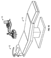
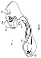
機械的な機能的インターフェースはいくつかの実施形態では再利用可能なモータ(例えば図18に示されるようなぜん動ポンプロータ、ローラおよびチューブを含む)と使い捨てポンプヘッドとの間の結合または再利用可能なポンプヘッドと使い捨てぜん動チューブ(ここでは例えば外科医または他の使用者は再利用可能なポンプヘッドの上に単回使用または有限使用のぜん動チューブを伸張または他の方法で導入するであろう)との間の結合を含み得る。機械的なインターフェースはまた、いくつかの実施形態では、例えば手持ち器具などの非隣接システムを作動するためにベルト、チェーン、伝達コイル、トルクコイル、ロータリケーブルおよび/またはそれらに類するものに接続されたモータまたは他のアクチュエータを含み得る。いくつかの実施形態では、モータまたはアクチュエータとその相手方構成要素との間のインターフェースは、スプライン結合、スパイダー結合、シャフト結合等などの機械的連結または結合であり得る。ロータリ機械的結合のいくつかの例が以下に記載されるように図2A〜2Kに示されている。 The mechanical functional interface can be coupled or reusable between the reusable motor (including, for example, a peristaltic pump rotor, rollers and tubes as shown in FIG. 18) and a disposable pump head in some embodiments Pump heads and disposable peristaltic tubes (where, for example, a surgeon or other user would extend or otherwise introduce a single-use or finite-use peristaltic tube over a reusable pump head) May include a bond between The mechanical interface is also, in some embodiments, connected to belts, chains, transmission coils, torque coils, rotary cables and / or the like to operate non-adjacent systems such as hand-held instruments It may include a motor or other actuator. In some embodiments, the interface between the motor or actuator and its counterpart component may be mechanical coupling or coupling such as spline coupling, spider coupling, shaft coupling, and the like. Some examples of rotary mechanical connections are shown in FIGS. 2A-2K as described below.
光学的な機能的インターフェースは、いくつかの実施形態では、再利用可能な光源と使い捨てファイバ、ファイバ束、光管および/または他の導波路との間の結合を含み得る。光源はいくつかの実施形態では内部照明、処置レーザ(例えば532nmまたは1064nmの光凝固)、またはイメージングレーザ(例えば光コヒーレンス断層撮影法)用の、LED(いくつかの実施形態ではRGBまたは白)または白色ランプであり得る。インターフェースはいくつかの実施形態ではレンズ、ミラー、ファイバ、ファイバ束、プリズム、光管および導波路および/または再利用可能な部分からシステムの使い捨て部分への光の案内かつ結合を補助する他の光学素子を含み得る。 Optical functional interfaces may include, in some embodiments, coupling between reusable light sources and disposable fibers, fiber bundles, light tubes and / or other waveguides. The light source is an LED (in some embodiments RGB or white in some embodiments) or an internal illumination in some embodiments, a treatment laser (for example 532 nm or 1064 nm photocoagulation), or an imaging laser (for example optical coherence tomography) It may be a white lamp. The interface is in some embodiments lenses, mirrors, fibers, fiber bundles, prisms, light pipes and waveguides and / or other optics that help guide and couple light from the reusable part to the disposable part of the system It may include an element.
流体的な機能的インターフェースはいくつかの実施形態では使い捨て柔軟性チューブと再利用可能なセンサ(例えば圧力センサ、流れセンサ、流体センサおよび/またはそれらに類するもの)との間のインターフェースまたは使い捨て柔軟性チューブとコンプレッサ、圧縮ガス、加圧液体、ポンプおよび/またはそれらに類するものなどの空気圧源または流体源との間のインターフェースを含み得る。インターフェースはいくつかの実施形態では、再利用可能な構成要素と使い捨て構成要素とが結合、組合せまたは互いに所望の位置に配置される場合に嵌合される流体コネクタを含み得る。 The fluidic functional interface in some embodiments is the interface or disposable flexibility between the disposable flexible tube and the reusable sensor (e.g. pressure sensor, flow sensor, fluid sensor and / or the like) An interface may be included between the tube and a pneumatic or fluid source such as a compressor, compressed gas, pressurized liquid, pump and / or the like. The interface may, in some embodiments, include fluid connectors that mate when the reusable component and the disposable component are combined, combined or placed in the desired position relative to one another.
いくつかの実施形態では、無菌使い捨てトレイ(またはその構成要素)は、例えば再利用可能モジュールに一体化された1つまたは複数のディスプレイを使用者が見ることを可能にするために透明または部分的透明材料を含む光学的な機能的インターフェースを含み得る。いくつかの実施形態では、無菌使い捨てトレイ(またはその構成要素)は、使用者が無菌使い捨てトレイを介して再利用可能なモジュール上に配置されたボタンを起動することを可能にするように構成された、薄い、柔軟性の、または曲げやすいあるいは順応性の材料を含み得る。いくつかの実施形態では、無菌使い捨てトレイは、薄い真空成形されたプラスチックおよび/またはそれらに類するものを含み得る。いくつかの実施形態では、透明材料の一部は、着色、染色または他の方法で不透明にされ得、その結果、材料の一部(光学的インターフェース部など)のみが使用中に透明のまま残る。 In some embodiments, the sterile disposable tray (or component thereof) is transparent or partially, for example, to allow the user to view one or more displays integrated in the reusable module. It may include an optical functional interface comprising a transparent material. In some embodiments, the sterile disposable tray (or component thereof) is configured to allow the user to activate a button disposed on the reusable module via the sterile disposable tray. It may include thin, flexible, flexible or flexible materials. In some embodiments, the sterile disposable tray may comprise thin vacuum formed plastic and / or the like. In some embodiments, part of the transparent material may be colored, dyed or otherwise opaque so that only part of the material (such as the optical interface portion) remains transparent during use .
本明細書に開示される機能的インターフェースはいずれも、再利用可能な構成要素が使い捨て構成要素に結合される(または使い捨て構成要素に対する所望の位置に配置される)とき、所望の位置または構成に自動的に係合または配置されるように構成または配置され得る。あるいは、1つまたは複数の機能的インターフェースは、再利用可能な構成要素が使い捨て構成要素に結合される前または後、使用者によって手動で係合されるように構成され得る。 Any of the functional interfaces disclosed herein are in the desired position or configuration when the reusable component is coupled to the disposable component (or placed in the desired position relative to the disposable component). It may be configured or arranged to be automatically engaged or arranged. Alternatively, one or more functional interfaces may be configured to be manually engaged by the user before or after the reusable component is coupled to the disposable component.
いくつかの実施形態では、再利用可能な部分および/または使い捨て部分は、それら部分のおよび/またはそれらの機能的インターフェースの嵌合または相互接続を補助するために、それら自体の整列、位置合わせまたは位置付けを補助する特徴部を含み得る。例えば、1つまたは複数の部分は、電気的接触または相互接続、機械的相互接続(例えば再利用可能モータシャフトと使い捨てぜん動ポンプロータ、カムおよび/またはそれらに類するものとの間の、または再利用可能ポンプモータおよびローラと使い捨てぜん動チューブとの間の)、空気圧的または流体的相互接続(例えば使い捨て部分を再利用可能センサ、空気圧源または流体源、圧縮ガス、ぜん動ポンプ、ベンチュリポンプ、および他のポンプ、および/またはそれらに類するものに接続するための)、および/または光学的相互接続(例えば使い捨て部分を再利用可能な光源、レーザおよび/またはそれらに類するものに接続するための)の整列または接続を補助するための特徴部を含み得る。いくつかの実施形態ではシステムの異なる構成要素を整列または固定するために磁石も使用され得る。再利用可能なモジュールはいくつかの実施形態では、無菌使い捨てトレイ(またはその構成要素)内に導入またはそれに取り付けられる(または結合される)と、自動的に電源をオンにされるか起動されるかイネーブルにされるか、またはそれが適切に「ドッキングされている」ことを判定するための手段を有し得る。 In some embodiments, reusable parts and / or disposable parts may be aligned, aligned or aligned themselves to assist in the fitting or interconnection of the parts and / or their functional interfaces. Features may be included to aid in positioning. For example, one or more parts may be in electrical contact or interconnection, mechanical interconnection (e.g., between reusable motor shaft and disposable peristaltic pump rotor, cam and / or the like, or recycled) Pneumatically or fluidly interconnect (eg disposable parts with reusable sensors, pneumatic source or fluid source, compressed gas, peristaltic pump, venturi pump, and other) Alignment of pumps, and / or to connect them, and / or optical interconnection (eg, to connect disposable parts to reusable light sources, lasers, and / or their like) Or, it may include features to assist in connection. Magnets may also be used to align or secure different components of the system in some embodiments. A reusable module, in some embodiments, is automatically powered on or activated when introduced into or attached to (or coupled to) a sterile disposable tray (or component thereof) It may be enabled or have means for determining that it is properly "docked".
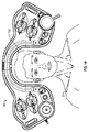
手術用トレイコンソール
図1A〜1Fは、眼科外科的処置で使用され得る手術用トレイ10の実施形態を示す。図1Aは患者2と一緒に使用する際の手術用トレイ10の頭上図または上面図を示す。この実施形態では手術用トレイ10は、患者の頭部周囲に配置された空隙または切欠き102を含む。図1B〜1Fはさらに手術用トレイ10と、手術用トレイ10を手術台、椅子またはストレッチャー13に取り付けることができる1つの方法とを示す。いくつかの実施形態では、図1Cに示されるような手術台13は、図1Bにより詳細に示される手首支持体などの支持体12を含む。支持体12は支持バー16と、手術台13の頭部に接続するように構成された端部14とを含む。図1Eに示されるように、いくつかの実施形態では、手術用トレイ10は、ベース部分104と嵌合するように構成された天板部分101を含み得る。ここに示されている実施形態においてベース104は、手術台13への天板部分101の効果的かつ構成可能な取付けを可能にする取付構造部分として望ましくは意図される。いくつかの実施形態では、本明細書中さらに記載されるように、ベース部分は、例えばモータおよび/またはポンプ、電子機器および/またはそれらに類するものなど、さらなる機能的特徴部を含み得る。ベース部分104は、ベース104を手術台13の支持体112に取り付けるまたは結合することを可能にするように構成された1つまたは複数の溝穴106または他の特徴部を含み得る。いくつかの実施形態では、ベース部分104を支持体112に保持するためにストラップが使用され、このときストラップは溝穴、溝、または凹部106を通過する。いくつかの実施形態では、手術用トレイ10は、とりわけ、天板部分101とベース部分104との間の弛みを除去し天板部分101とベース部分104との間のより頑丈な接続を維持することを補助するようにベース部分104の頂部に配置されたパッド108を含む。
Surgical Tray Console FIGS. 1A-1F illustrate an embodiment of a
図1Fで見ることができるように、いくつかの実施形態では、手術用トレイは、ベースと摺動可能に係合するように構成される。この実施形態では、手術用トレイ天板部分101は、ベース104と係合するラッチ126を含む。いくつかの実施形態では、レバーまたはスイッチまたはハンドル124により、手術用トレイ10の使用者は天板部分101を適所でベース104と選択的に係合またはロックすることが可能になる。いくつかの実施形態では、ラッチ126は、天板部分101が、異なる大きさの患者および/または使用者の嗜好を受け入れるためなど、複数の位置でロックすることを可能にするために調整可能である。例えば、手術用トレイ10の底面図である図1Fに示される実施形態では、天板部分101は、完全係合位置のほぼ半分の位置で適所にロックされた状態で示されている。
As can be seen in FIG. 1F, in some embodiments, the surgical tray is configured to slideably engage with the base. In this embodiment, the surgical
天板部分101、ベース104および支持体112の分解図である図1Eは、手術用トレイ10のいくつかの特徴部を示す。例えば、手術用トレイ10は、1つまたは複数のハンドピースまたは手術器具110を、この実施形態では4つのハンドピース110を含む。ハンドピース110は、例えば硝子体切断、ジアテルミーまたは電気焼灼、照射および/またはそれらに類する機能などの手術的機能を実行するための1つまたは複数の器具を含み得る。いくつかの実施形態では、ハンドピース110は、ケーブルまたはテザー112を介して天板部分101に繋ぎ止められる。いくつかの実施形態では、ケーブルまたはテザー112は、例えば動力伝達、電子的通信、空気圧的または光学的など他の方法を介した通信、および/またはそれらに類似する特徴など、1つまたは複数の特徴を含む。
FIG. 1E, which is an exploded view of the
手術用トレイ10はさらに、ハンドピースが必要とされるまでおよび/または次の外科的処置までの間、ハンドピースを適所に保持するためにハンドピース110と係合するように構成された複数の凹部または保管構造111を含む。手術用トレイ10はさらに、例えば流体注入、油注入、空気注入および/またはそれらに類する機能など手術用トレイ10の複数の機能を制御するための複数の制御装置114を含む。手術用トレイ10はさらに、手術用トレイ10の1つまたは複数の装置に対する動力を操作するように構成された動力ボタン116を含む。手術用トレイ10の1つまたは複数のディスプレイまたはインジケータおよび/または光源118は、外科的処置の間、情報が、例えば使用者または外科医に伝達されることを可能にする。いくつかの実施形態では、1つまたは複数のディスプレイまたはインジケータ118は手術用トレイ10から離れて、例えば顕微鏡にまたは壁に配置され、有線または無線接続を介してトレイに接続されてもよい。手術用トレイ10はさらに流体貯蔵器受入装置120および平衡塩類溶液(BSS)ボトル、容器、無菌筐体または他のホルダ122を含む。この実施形態では、モータは、図1Fに示されるポンプヘッド123に対し取外し可能であり、および/または取外し可能に結合される。ポンプヘッドはさらにポンプ入力および/または出力チューブ123を含む。いくつかの実施形態では、モータを手術用トレイ10および/またはポンプヘッド123から取外し可能とし、それにより、例えば、比較的高価なおよび/またはより高い品質のモータが利用され得る一方で、ポンプヘッド123を含む手術用トレイ10の残部は単回処置または所定の処置回数後に処分できるようにすることが望ましいことがあり得る。モータをポンプヘッド123に結合するために使用され得る結合機構の様々な実施形態を、図2A〜2Kを参照して以下でさらに詳細に記載する。
The
いくつかの実施形態では、例えば図1A〜1Fに示される手術用トレイ10など、本明細書に開示される1つまたは複数の手術用トレイは、STERILE SURGICAL TRAYという名称の米国特許第8,568,391号明細書に記載されているものと同様の1つまたは複数の特徴および/またはそれと同様に作動し得る1つまたは複数の特徴を含み得、前出の特許はその全体が参照により本明細書に援用される。
In some embodiments, one or more of the surgical trays disclosed herein, such as, for example, the
様々な実施形態は、トレイの機能を制御する取外し可能および/または取外し不可能な電子機器を含み得る。電子機器は、1つまたは複数のマイクロコントローラ、マイクロプロセッサ、マイクロエレクトロニクス、および/またはそれらに類するものを含み得、電子機器は、圧力、真空、流れ、温度、光強度、電圧/電流/電力、および慣性測定センサを含むがそれらに限定されない様々なセンサのいずれかを含み得る。電子機器はまた、低コストであるように、従って単回使用後または制限された使用回数後に処分できるように設計され得る。電子機器は、製造者によって意図されていた使用を超える電子機器の使用を防止するソフトウェアまたはハードウェア特徴部を含み得る。例えば、電子機器は、患者に安全リスクが生じ得る(例えばシステムがもはや無菌でないために)再使用を防止するために、および製造業者の販売収入を保護するために単回使用後に動作不能になり得る。電子機器はまた、いくつかの実施形態では、制限された使用回数、制限時間量の間、または所定の使用期限まで機能するように設計され得る。例えば、これは、信頼できると考えられる使用を超えるシステムの使用を防止するのに有用であろう(例えば、特定の構成要素は故障の可能性が危険な状態になる前に制限された使用回数を有し得るか、またはシステムの特定の構成要素の効力または無菌性は制限された寿命を有し得る)。これはまた、記名式販売モデルで使用され得、その際、外科医または病院は、追加の外科的処置用にシステムを使用するために、またはシステムの追加機能を加える/ロック解除するために、追加のクレジットを購入することができる。いくつかの実施形態はまた、再利用を制限する非電子的および非ソフトウェア手段を利用し得、例えばハンドピースおよび/またはトレイ構成要素はオートクレーブ滅菌に耐えない材料から製造され得る。 Various embodiments may include removable and / or non-removable electronics that control the functionality of the tray. The electronics may include one or more microcontrollers, microprocessors, microelectronics, and / or the like, where the electronics are pressure, vacuum, flow, temperature, light intensity, voltage / current / power, And any of a variety of sensors, including but not limited to inertial measurement sensors. The electronics can also be designed to be low cost and thus be disposable after a single use or after a limited number of uses. The electronics may include software or hardware features that prevent the use of the electronics beyond the use intended by the manufacturer. For example, the electronics can become inoperable after a single use to prevent re-use, which may pose a safety risk to the patient (eg because the system is no longer sterile), and to protect the manufacturer's sales revenue obtain. The electronics may also be designed, in some embodiments, to function for a limited number of uses, for a limited amount of time, or until a predetermined expiration date. For example, this may be useful to prevent the use of the system beyond the use considered to be reliable (e.g. certain components may have a limited number of uses before the possibility of failure is at risk) Or the efficacy or sterility of certain components of the system may have a limited lifetime). This can also be used in a registered sales model, where the surgeon or hospital adds to use the system for additional surgical procedures or to add / unlock additional features of the system You can buy credits for. Some embodiments may also utilize non-electronic and non-software means to limit reuse, for example, handpiece and / or tray components may be manufactured from materials that do not withstand autoclave sterilization.
いくつかの実施形態のトレイは内部電源、または変圧器およびAC壁電流をより低い電圧DCに変換する整流器を組み込み得る。トレイは代替的にトレイから分離された電源(例えば「壁のこぶ(wall−wart)」型変圧器または外部ブリック状電源)を利用し得る。トレイはまた、1つまたは複数の単回使用型(一次)バッテリ(例えば、アルカリ、リチウム、マンガンまたは他の化学的性質)または充電可能型(二次)バッテリ(例えばLi−ion、Li−Poly、NiMH、NiCdまたは他の化学的性質)によって動力供給され得る。バッテリは、いくつかの実施形態では、トレイ自体から取り出し可能な自蔵型バッテリパックとして構成され得る。トレイはまた、トレイが結合される別個のコンソールシステムから、または外科用顕微鏡から動力(電気的、空気圧的および/または他の方式)を得る場合がある。 The trays of some embodiments may incorporate an internal power supply, or a transformer and a rectifier that converts AC wall current to a lower voltage DC. The tray may alternatively utilize a power supply separate from the tray (e.g., a "wall-wart" type transformer or an external brick-like power supply). The trays may also be one or more single-use (primary) batteries (eg, alkaline, lithium, manganese or other chemicals) or rechargeable (secondary) batteries (eg, Li-ion, Li-Poly) , NiMH, NiCd or other chemical properties). The battery may, in some embodiments, be configured as a self-contained battery pack that can be removed from the tray itself. The tray may also get power (electrically, pneumatically and / or otherwise) from a separate console system to which the tray is coupled or from a surgical microscope.
トレイ自体と別個の再利用可能または半永久的ベースを含む実施形態において、ベースは、トレイの製造コストを削減すること、ごみを削減すること、およびより高い品質の再利用可能な構成要素を使用することを含む利点のために以下のいずれか1つまたはいくつかを組み込むように設計され得る:電子装置;ディスプレイ;センサ(例えば圧力、流れ);電源;1つまたは複数の一次または二次バッテリまたはバッテリパック;例えば注入、吸引、および/または空気圧もしくは液圧器具を駆動するためのポンプまたはポンプの構成要素およびサブアセンブリ(例えばモータおよび駆動回路);ハンドピース駆動モータ(例えば硝子体カッターまたは他の機械的器具に接続された伝達ケーブルまたはトルクコイルを移動または回転するためのもの);内部照明光源;光凝固レーザ。ベースおよびトレイは、トレイが一時的であるが確実にベースに取り付けられることを可能にし、ならびに例えば異なる患者の形状を受け入れるためにトレイの位置を調整または平行移動することを可能にする特徴部を実装し得る。さらに別の実施形態では、これらの特徴部のいくつかまたは全ては、手術用トレイおよびハンドピースの機能を制御するために使用される1つのフットペダル(または2つ以上のフットペダル)に配置され得る。フットペダルは、電気的接続(例えばケーブルアセンブリ)、空気圧/液圧的接続(例えばチューブ)、光学的接続(例えば、照明、レーザ治療、撮像等用に使用可能な広帯域または狭い帯域の波長光用の1つまたは複数の光ファイバ)、および機械的連結接続(例えば、フットペダル筐体に配置されたモータ、ピストン等の運動をトレイまたはハンドピースに伝達するための伝達ケーブルまたはコイル)を介して、トレイおよび/またはハンドピースに繋ぎ止められ得る。関連の実施形態では、フットペダルは、これらの要素のいくつかを含み得るが、ポンプと患者との間のチューブ長さが最小化されるようにベースユニットまたはトレイに配置されたポンプ(例えば注入および/または吸引用)に接続され得る。 In embodiments that include a reusable or semi-permanent base separate from the tray itself, the base reduces the manufacturing cost of the tray, reduces waste, and uses higher quality reusable components. Can be designed to incorporate any one or more of the following for advantages including: electronic devices; displays; sensors (eg pressure, flow); power supplies; one or more primary or secondary batteries or Battery pack; eg pump or pump components and subassemblies (eg motor and drive circuit) for driving eg injection, suction and / or pneumatic or hydraulic instruments; handpiece drive motors (eg vitreous cutter or other) Move or rotate the transfer cable or torque coil connected to the mechanical device Ones); internal light source; photocoagulation laser. The base and tray allow features that allow the tray to be temporarily but securely attached to the base, and allow features such as adjusting or translating the position of the tray to accommodate different patient shapes, for example. It can be implemented. In yet another embodiment, some or all of these features are located on one foot pedal (or more than one foot pedal) used to control the function of the surgical tray and hand piece obtain. Foot pedals can be used for electrical connections (eg cable assemblies), pneumatic / hydraulic connections (eg tubes), optical connections (eg lighting, laser treatment, imaging etc.) for broadband or narrow band wavelength light And one or more of the optical fibers) and a mechanical connection (eg, a motor disposed in the foot pedal housing, a transfer cable or coil for transferring movement of a piston or the like to the tray or hand piece) , Trays and / or handpieces. In related embodiments, the foot pedal may include some of these elements, but the pump (e.g., an infusion) disposed on the base unit or tray such that the tube length between the pump and the patient is minimized. And / or for suction).
別個のベース内にポンプモータおよび/またはハンドピース駆動モータを備えた実施形態において、ポンプモータはトレイ内のポンプヘッドと結合し得、および駆動モータは、トレイがベースに取り付けられるか配置されると整列されかつ係合するスプライン結合、シャフト結合または同様のものを介して伝達ケーブルまたはトルクコイルと結合し得る。図2A〜2Kは、モータ入力シャフトおよび/またはトルク伝達機構204のポンプヘッド202への取外し可能な結合を可能にするように構成され得る結合装置または結合機構205の様々な実施形態を示す。ここに示されている実施形態は、ポンプ側結合部分206とモータ側結合部分208とを含む。図2A〜2Cに示される実施形態において、ポンプ側結合部分206は、モータ結合部分208の雌型スプラインと結合するように構成された雄型スプラインを含む。雄型スプライン206は、雌型スプライン208と摺動可能に結合しトルクがモータからポンプヘッド202へ伝達されることを可能にするように構成され得る。図2Dは、結合装置205の実施形態を示し、ここでは雄型部分206および雌型部分208は、それらを介したトルクの伝達を可能にする六角ヘッドボルトおよびソケットと同様に、嵌合用平坦部を含む。図2E〜2Kは様々な実施形態を示し、ここではポンプ側結合部分206の交互に存在する頂部および窪みが、モータ側部分208の交互に存在する頂部および窪みと係合し、それらを介したトルクの伝達を可能にする。様々な他の取外し可能なトルク伝達結合装置が代替的に使用され得る。他の実施形態では、ポンプモータおよびポンプヘッドは簡単に分離できず、代わりにポンプチューブがポンプヘッドから分離可能である。
In embodiments where the pump motor and / or the handpiece drive motor are in separate bases, the pump motor may be coupled to the pump head in the tray, and the drive motor may be configured such that when the tray is attached to or disposed at the base It may be coupled with the transfer cable or torque coil through aligned and engaged splined connections, shafted connections or the like. 2A-2K illustrate various embodiments of coupling devices or
機能的無菌バリヤ
いくつかの実施形態では、眼科手術システムは、トレイをベースに配置する前に無菌バリヤを形成するために非無菌永久ベースを布で覆うために使用可能なドレープなどの特注無菌バリヤを含む。ドレープはいくつかの実施形態ではベースおよびトレイに形状が適合され得る。ドレープはいくつかの実施形態では、光、電気装置、機械的装置および/またはそれらに類するものがそれを通過することを可能にする1つまたは複数の特徴部などの1つまたは複数の機能的特徴部を含み得る。例えば、ドレープは、ベース内のディスプレイを見ることを可能にする1つまたは複数の透明な窓を含み得る。いくつかの実施形態では、ドレープは、電気的、機械的および/または流体的/空気圧的な接続がトレイとベースとの間に設けられることを可能にするためにトレイがベースに取り付けられるとき破られるか穴あけされる穿孔を含み得る。いくつかの実施形態では、ドレープは穿孔を一切含まないこともあるが、それにもかかわらず、トレイおよびベースが嵌合されるとき特定の領域に穿刺または穿孔され得る。いくつかの実施形態では、トレイおよびベースは、設置プロセスの間無菌バリヤが確実に維持されるように穿孔が形成される前に穿孔される領域の周囲にシールを形成し得る。いくつかの実施形態では、ドレープは、ドレープを破ることもなければ穿刺することもなく、および無菌バリヤを妥協することもなく1つまたは複数の電気的接続がベースとトレイの間に形成できるように一体化された電気接点を有し得る。これらの電気接点はいくつかの実施形態では、別個の接点をドレープ材料に一体化することによって形成され得、またはドレープ材料自体が、異方性伝導性である材料から作製され得るかそのような材料を適切な領域に組み込み得、その結果、電流が薄いドレープ材料を通って流れることができるが、多数の隣接する電流経路は互いに相互作用しない。他の実施形態では、動力はドレープの両側に配置された2つのアンテナの誘導結合を経由して、または同様の無線式動力伝送方法を経由して、ドレープを介して無線式に伝送される。
Functional Aseptic Barriers In some embodiments, the ophthalmic surgery system is a custom aseptic barrier such as a drape that can be used to cloth a non-sterile permanent base to form a sterile barrier prior to placing the tray on the base. including. The drape may be conformed in shape to the base and tray in some embodiments. The drape is, in some embodiments, one or more functional, such as one or more features that allow light, electrical devices, mechanical devices and / or the like to pass through it. It may include features. For example, the drape may include one or more transparent windows that allow the display in the base to be viewed. In some embodiments, the drape breaks when the tray is attached to the base to allow an electrical, mechanical and / or fluid / pneumatic connection to be provided between the tray and the base It can include perforations that are drilled or drilled. In some embodiments, the drape may not include any perforations, but nevertheless may be punctured or perforated in specific areas when the tray and base are mated. In some embodiments, the tray and base may form a seal around the area to be perforated before the perforations are formed to ensure that the sterility barrier is maintained during the installation process. In some embodiments, the drape is such that one or more electrical connections can be made between the base and the tray without breaking or piercing the drape and without compromising the sterility barrier. Can have integrated electrical contacts. These electrical contacts may, in some embodiments, be formed by integrating separate contacts into the drape material, or such that the drape material itself may be made of a material that is anisotropically conductive. Material can be incorporated into the appropriate area so that current can flow through the thin drape material, but multiple adjacent current paths do not interact with one another. In another embodiment, power is wirelessly transmitted via the drape via inductive coupling of two antennas located on either side of the drape, or via a similar wireless power transmission method.
図3Aは、複数の機能的特徴部を組み込むドレープ300の実施形態の上面図を示す。ドレープ300は、手術中無菌バリヤを確実に維持するために、例えば手術用トレイのベース部分およびまたは患者の頭部を覆って掛けられるように構成および/または成形および/または寸法決めされた柔軟性材料のシート302を含む。いくつかの実施形態では、ドレープは、以下でさらに考察されるように、図4Fに示されるものなど、少なくとも部分的に手術用トレイのベース部分と天板部分との間に配置されるように構成される。図3Aに示される実施形態において、ドレープ300は、簡単にするため長方形として示されている。しかしながら、他の実施形態では、ドレープ300は、ドレープが手術用トレイの少なくとも一部を覆って所定の構成で配置されることができるように異なって成形され得、および/または注文に応じて適合され得る。
FIG. 3A shows a top view of an embodiment of a
ドレープ300は、使用者がそれを通して手術用トレイの1つまたは複数のディスプレイを見ることができるように配置された透明領域などの2つの窓304を含む。例えば、窓304は、以下でさらに記載されるように、使用者が図4Aに示されるディスプレイ118を見ることができるように配置され得る。ドレープ300はさらに、穿孔を含む穿孔領域306を含み、穿孔はドレープ300が適所に配置されるとき穿孔領域306が破られおよび/または取り除かれることを可能にし、機能的装置がそこを通過することを可能にする。例えば、電気的接続がそこを通過し得、機械的結合がそこを通過し得、空気圧的および/または流体的結合がそこを通過し得、光学的結合がそこを通過し得、および/またはそれに類するものがそこを通過し得る。ドレープ300はさらに代替的な穿孔構造308を含む。穿孔308は、チューブまたは他の機能的部材がそこを通過することを可能にするためになど、十字の形状の穿孔を含む。
いくつかの実施形態では、ドレープ300の1つまたは複数の機能的領域は、穿孔308の周囲の円形領域として図3Aに示されるシール部分310を含む。シール部分310は、例えば、穿孔308が破られるまたは裂かれる、すなわち開口される前に、例えば手術用トレイの天板部分と底部分との間に無菌シールを形成することを可能にするまたは補助する材料を含み得る。いくつかの実施形態では、シール部分310は、ゴムなどの弾性材料を含み得る。いくつかの実施形態では、シール部分310は、主ドレープ材料302よりも硬い材料のリング(または他の方法で成形される)を含む。
In some embodiments, one or more functional areas of the
いくつかの実施形態では、ドレープ300は、電気接点部分または領域またはブロック312を含む。電気接点部分312はこの実施形態では、ドレープ300の片側の相手方接点をドレープ300の反対側の相手方接点と電気的に連通させることを可能にする電気伝導性材料などの複数の電気接点314を含む。図3Bは電気接点部分312の断面を示す。この実施形態では複数の電気接点314がドレープ300の片側からドレープ300の反対側へ通過し、従って電流が同じく、無菌側などのストリート300の片側から非無菌側などのドレープ300の反対側へ通過することを可能にすることを図3Bで見ることができる。
In some embodiments, the
図3Cは電気接点部分312’の代替実施形態の断面を示す。この実施形態では、電気接点部分312’は、図3Cに概略的に示されるような異方性導電性材料を含み、異方性導電性材料は、電流がドレープ300の片側からドレープ300の反対側へなど、一方向に移動することを可能にするが、横切る方向、すなわち垂直方向に移動することを不可能にする。従って、トレイの天板部分の複数の電気接点は、電気接点部分に複数の離散した電気接点を必要とすることなく電気接点部分312’を介して手術用トレイの底部分の複数の電気接点と電気的に連通するように構成され得る。これは、とりわけ、低減された製造コストおよび/または手術用トレイに対するドレープの位置の増大した許容度を可能にし得る。
FIG. 3C shows a cross section of an alternative embodiment of the electrical contact portion 312 '. In this embodiment, the
モジュール式手術用トレイシステム
いくつかの実施形態では、本明細書に記載されるような手術用トレイはモジュール式であり得、1つまたは複数のモジュールがそれに結合されるように構成されたベース、すなわち再利用可能な部分を有する。いくつかの実施形態では、ベース部分は、少なくとも所定の処置回数および/または使用長さの間、再利用できるように構成される一方で、モジュールの実施形態における1つまたは複数は単回使用後などに処分できるように構成される。いくつかの実施形態では、モジュール式手術用トレイシステムは、再利用可能底トレイ部分に結合された使い捨て天板トレイ部分を含む。いくつかの実施形態では、モジュール式手術用トレイシステムは、モータ/ポンプモジュール、流体貯蔵器受入装置モジュール、電流アダプタモジュール、1つまたは複数のハンドピースを含むモジュール式器具インサート、および/またはそれらに類するものなど、1つまたは複数の機能的モジュールを挿入するための1つまたは複数の位置を有する再利用可能トレイを含む。
Modular Surgical Tray System In some embodiments, a surgical tray as described herein may be modular and a base configured to have one or more modules coupled thereto, That is, it has a reusable part. In some embodiments, the base portion is configured to be reusable for at least a predetermined number of treatments and / or length of use while one or more of the module embodiments are after a single use It is configured to be disposable. In some embodiments, a modular surgical tray system includes a disposable top tray portion coupled to a reusable bottom tray portion. In some embodiments, the modular surgical tray system comprises a motor / pump module, a fluid reservoir receiver module, a current adapter module, a modular instrument insert comprising one or more handpieces, and / or And the like, including reusable trays having one or more locations for inserting one or more functional modules.
いくつかの実施形態では、ベース部分など、モジュール式手術用トレイシステムの再利用可能な部分は、1つまたは複数のモジュールの1つまたは複数の使い捨て機能ユニットと結合する、連通するおよび/またはそれらに類する状態であるように構成された1つまたは複数の再利用可能な機能的ユニットを含む。例えば、いくつかの実施形態では、再利用可能ベース部分は、使い捨てモジュール部分の使い捨てポンプハウジングと結合するように構成されたモータを含み得る。いくつかの実施形態では、手術用トレイシステムまたはアセンブリのベース部分など、再利用可能な部分は、1つまたは複数の手術用具の動作を制御するように、および/または1つもしくは複数の制御装置および/もしくは使い捨て部分の手術用具からの入力または状況を検出するように構成された電気処理ユニットを含み得る。いくつかの実施形態では、モジュール式手術用トレイシステムは、再利用可能、すなわちベース部分と使い捨ての、すなわち天板部分またはモジュールとの間に配置されるように構成された図3A〜3Cに関連して上に記載したような特注手術用ドレープを含む。 In some embodiments, a reusable portion of a modular surgical tray system, such as a base portion, is coupled to, in communication with and / or in one or more disposable functional units of one or more modules. And one or more reusable functional units configured to be similar to one another. For example, in some embodiments, the reusable base portion can include a motor configured to couple with the disposable pump housing of the disposable module portion. In some embodiments, the reusable portion, such as the base portion of the surgical tray system or assembly, controls operation of one or more surgical tools, and / or one or more control devices And / or may include an electrical processing unit configured to detect input or status from the surgical tool of the disposable portion. In some embodiments, the modular surgical tray system is associated with FIGS. 3A-3C, which is reusable, ie, configured to be disposed between the base portion and the disposable, ie top plate portion or module. And customized surgical drapes as described above.
図4Aは、底部分、すなわち再利用可能な部分404と結合された天板、すなわち使い捨て部分402を含むモジュラー式手術用トレイシステムの実施形態の斜視図を示す。底部404は、手術台の頭部の支持体などの支持体112に結合される。底部404は、例えば、図4Bに示されるストラップ412など、溝穴を通過するストラップなどの様々な方法で支持体112と連結されるように構成され得る。図4Aに示される手術用トレイ410は、例えば、複数のハンドピース110、ハンドピース用保管または支持位置111、ハンドピース110をこの実施形態では底部404に接続する複数のテザーまたはケーブル112、複数の制御装置114、動力ボタン116、2つのディスプレイ118、流体貯蔵器受入装置120、およびBSSボトル122など、本明細書に記載される他の実施形態の特徴部に設計が類似した複数の特徴部を含む。図4Aに示される実施形態は追加的に、手術用トレイシステム410の1つまたは複数の特徴部の制御を可能にするために底部404に繋がれたまたはそれと連通するフットペダル406を含む。
FIG. 4A shows a perspective view of an embodiment of a modular surgical tray system that includes a top or
図4Bは手術用トレイシステム410の分解図を示し、支持体112に取り付けられたベース部分404を示すが、天板、すなわち使い捨て部分402はベース部分404に依然として結合されていない。この実施形態では、ベース部分404のいくつかの機能的特徴部が示され、それにはディスプレイ118、光源418(この実施形態ではLEDであり、他の実施形態では光源はレーザ、ハロゲンランプ、またはそれらに類するものであることができる)、および2つのポンプ414が含まれる。図4Cは、天板部分402と底部分404との間の電気的接続を可能にする機能的特徴部の別の例を示す。この実施形態では、テザーまたはケーブル112が、使い捨てトレイ部分402の一部であるかそれに結合される天板電気コネクタ418に接続される。天板コネクタ部分418は、複数の電気接点またはピン419を含み、複数の電気接点またはピン419は天板コネクタ部分から突出し、かつベース部分404の一部であるかそれに結合される底部コネクタ部分420の相手方電気接点421と係合するように構成される。従って、この実施形態では、ハンドピースは、天板部分402をベース部分404に結合するとベース部分404の電子機器または他の特徴部に自動的に接続され得る。換言すると、システムの使用者は、ベース部分404の上に手術用トレイ天板部分402を配置した後、各ハンドピースを個々に差し込まなくてもよい。いくつかの実施形態では、そのような構成は、例えば、より高価なおよび/または耐久性のある構成要素がベース、すなわち再利用可能な部分404の一部であることまたはそれと結合されることを可能にする一方で、使い捨て部分402の天板が1回の手術に利用され手術後に処分される準備が出来ている単一無菌アセンブリとして提供され得るのに有利であり得る。
FIG. 4B shows an exploded view of the
図4Dは手術用トレイシステム410の上面図を示す。図4Eは手術用トレイシステム410の天板、すなわち使い捨て部分402の底面斜視図を示す。図4Eの見た目は、ディスプレイ118を見るための開口408と、BSSボトル122に結合されたポンプヘッドに機械的に結合されるように構成された結合装置など、モータ122Aの駆動部分204とをより詳細に示す。いくつかの実施形態では、上に記載したように、モータ122Aは再利用可能であるように構成され得、および/または別の使い捨て部分402と一緒に使用するために天板、すなわち使い捨て部分402から取外し可能であるように構成され得る。
FIG. 4D shows a top view of the
図4Fは、ドレープ430が間に配置された状態で底部404の上に位置付けられている手術用トレイシステム410の天板、すなわち使い捨て部分402の完全組み立て図および分解図を示す。ドレープ430が、ドレープ430を介して底部分404のディスプレイを見ることを可能にするディスプレイ窓432を含むことを図4Fで見ることができる。ドレープ430はさらに、図3A〜3Cを参照して上に記載したような、1つまたは複数の追加の機能的インターフェースを含み得る。
FIG. 4F shows a fully assembled and exploded view of the top or
図5Aは、底部、すなわち再利用可能な部分504に結合された天板、すなわち使い捨て部分502を含むモジュール式手術用トレイシステムは510の別の実施形態を示す。モジュール式手術用トレイシステム510は上に記載したモジュール式手術用トレイシステム410に機能的に類似しているが、特徴部のいくつかの異なる配置および/または設計を有する。手術用トレイシステム510の様々な要素は、手術用トレイシステム410の特徴部に類似した特徴部を表すために同様の参照番号を使用する。図5Bは手術用トレイシステム510の上面図を示し、ここではハンドピースは取り外され、完全なハンドピース支持または保管位置111を示している。さらに、BSSボトル122は取り外され、モータ受入れポケットまたは領域502をより詳細に示している。
FIG. 5A shows another embodiment of a modular
図6A〜6Fはモジュール式手術用トレイシステム610の別の実施形態を示している。この実施形態では、モジュール式手術用トレイシステム610は、1つまたは複数のモジュールを受け入れるまたはそれと結合するように構成された複数の位置またはインターフェース部を有する再利用可能な、すなわちベース部分650を含む。この実施形態では、システム610は、モータおよびポンプモジュール622、流体貯蔵器受入装置モジュール620、動力アダプタモジュール654、およびモジュール式器具インサート652を含む。ある実施形態では、モータおよびポンプモジュール622は、BSSボトルホルダを含むことができる。ある実施形態では、モータおよびポンプモジュール622は、注入ポンプおよび/または圧力センサ用の駆動電子装置を含むことができる。ある実施形態では、駆動電子装置および/または圧力センサは、トレイの再利用可能な部分に位置付けることができる。ある実施形態では、流体貯蔵器受入装置モジュール620は、吸入流体貯蔵器および吸入ポンプを含むことができる。ある実施形態では、流体貯蔵器受入装置モジュール620は、吸入ポンプおよび圧力センサ用の駆動電子装置を含むことができる(またはこれらの一方または両方が代わりにトレイの再利用可能な部分に位置付けられ得る)。ある実施形態では、動力アダプタモジュール654は、ディスプレイの1つに組み込むことができる。ある実施形態では、動力アダプタモジュール654は、トレイの下方に(再利用可能な部分に)または他の場所に(例えば地面またはそれに類する場所に)位置付けることができる。図6Bはモータおよびポンプモジュール622(またはいくつかの実施形態ではBSSボトルホルダ622)の側面図を示す。図6Cは流体貯蔵器受入装置モジュール620の側面図を示す。図6Dはモータおよびポンプモジュール622(またはいくつかの実施形態ではBSSボトルホルダ622)、流体受入装置モジュール620、および無菌作業環境で使用する準備が出来ている無菌パッケージまたはアセンブリとして実現し得るものなど、モジュール式工具インサート652の斜視図を示す。この実施形態では、モジュール式工具インサート652がインサートの全体梱包サイズを低減するために、例えば保管または輸送の間サイズを低減するためにインサートをそれ自体の上に折り畳むことを可能にする折り畳みまたはヒンジジョイント653を含むことを見ることができる。
6A-6F illustrate another embodiment of a modular
図6Eは、BSSホルダも流体受入装置も工具インサートモジュールも結合されていないベース部分650の斜視図を示す。ベース部分650は、流体受入装置モジュール620と結合するように成形または構成された流体受入装置インターフェース部621と、モータおよびポンプモジュール622(またはBSSモジュール622)と結合するように構成または成形されたモータインターフェース部623(またはBSSインターフェース部623)とを含む。ベース部分650はさらに、工具インサート652を配置および/または保持するための凹部領域を含む2つの工具インサートインターフェース部653を含む。図6Aはさらに、ベース部分652を支持体112に保持するように構成されたストラップ412を示す。いくつかの実施形態では、ストラップ412(またはベース部分650の別の部分)は、フックアンドループ式ファスナ、磁石および/またはそれらに類するものなど、モジュール式工具インサート652をベース部分650に保持することを補助する特徴部を含み得る。図6Fはモジュール式手術用トレイシステム610の分解図を示す。
FIG. 6E shows a perspective view of the
図6A〜6Eに示される例示的実施形態において、再利用可能な部分650は、手術ベッドまたは椅子に直接または間接的に取り付けられるベースを含む。再利用可能な部分650は電子装置、ディスプレイ、モータ、ポンプ、コンプレッサまたは圧縮ガス源、センサ、光源、電源、バッテリおよび/またはそれらに類するものを含み得る。使い捨て部分652は、半分の所で折り畳まれ得るかヒンジ接続され得るトレイ(例えば真空形成または成形されたプラスチックトレイ)を含み得、トレイは開く、広げるまたは梱包から取り出すと、直接または間に無菌ドレープを備えた状態で、再利用可能トレイ650に配置することができる。使い捨てトレイ652はハンドピース110、流体構成要素、光学構成要素、ポンプ、電子装置、モータおよびアクチュエータ、および/またはこれらまたは他の構成要素の一部を含み得る。使い捨てトレイ652はいくつかの実施形態では位置合わせ特徴部、切欠き、竪穴、ポケット、磁石および/またはそれらに類するものを用いて再利用可能な部分650に取り付けまたは装着され得る。
In the exemplary embodiment shown in FIGS. 6A-6E, the
他の実施形態では、再利用可能ベース650は、能動的構成要素(例えば電子装置、ディスプレイ、モータ、ポンプ、コンプレッサまたは圧縮ガス源、センサおよび/またはそれらに類するもの)をほとんどまたは全く組み込まず、使い捨てトレイ652(および/またはBSSボトルおよび貯蔵器モジュール622、620)に構造的支持体を単に提供する。再利用可能トレイ650はいくつかの実施形態では無菌バリヤを提供するために標準的なドレープで覆われその上に使い捨てトレイ652が配置され得る。なぜなら、再利用可能な部分650が能動的または機能的構成要素を全く組み込まない実施形態ではドレープを介した機能的なインターフェースは必要ないためである。そのような場合に、再利用可能トレイ652は、再利用可能な機能的モジュールを、例えば無菌環境から隔絶されたキャビティ内に収容するために特徴部(例えば図12A〜12Cおよび13A〜13Cを参照して以下に記載されるものと同様のもの)を含み得る。
In other embodiments,
追加的な構成要素も他の関連実施形態に存在し得る。例えば、図6A〜6Fに示されるようなモジュール式構成要素620、622(使い捨て型または再利用可能のいずれか)は、再利用可能トレイ650に配置することができる。いくつかの実施形態では、注入機能および吸引機能が、別個のモジュール620、622に分離され、別個のモジュール620、622はいずれかの機能に必要な構成要素の一部または実質的に全部の構成要素を含む。図6A〜6Fでは、吸引および注入モジュール620、622は、同じ形状係数を共有しかつ再利用可能トレイ650の両側に導入可能な2つの別個のモジュールである。これは、例えば、吸引モジュール620または他の機能的構成要素またはモジュールを保持するために反対側スペースを場合により使用しながら外科的処置を受ける目に隣接した注入モジュール622の配置を可能にするのに有益であり得る。
Additional components may also be present in other related embodiments. For example,
図6Fは、場合により無菌ドレープ、バッグまたは類似のものによって分離される、再利用可能な部分または別個の使い捨て部分650の上に配置または支持される(例えば射出成形または真空形成された)使い捨てトレイ652を展開する例を示す。展開された使い捨てトレイ652はいくつかの実施形態では、本明細書に開示される他の実施形態に関連してさらに考察されるように、例えば様々な整列特徴部または磁石を介して、再利用可能な底部分650の上に整列し得る。折り畳み可能な使い捨てトレイ652はハンドピース110を含み得、および/またはそれは吸引機能的モジュールおよび/または注入機能的モジュール(ポンプ、モータ、ポンプヘッド、流体貯蔵器タンク、電子装置;チューブ、フィルタ、止水栓、流体コネクタおよび/またはそれらに類するものを含む流体構成要素のいくつかまたは全てを含む)などの他の機能的要素も含み得る。あるいは、いくつかの実施形態では、それら機能的モジュールのいくつかまたは全ては、ハンドピース110を保持する使い捨てトレイ部分652と別個のものであることができる。
6F is a disposable tray (eg, injection molded or vacuum formed) disposed or supported on a reusable or separate
トレイはいくつかの実施形態ではまた別個の手術用コンソールに接続するか連結するように設計され得る。トレイおよびコンソールは互いに電気的、機械的、空気圧的、液圧的、無線式または他のインターフェース部を共有し得る。例えば、いくつかの実施形態では、トレイは、患者の近くに都合よく配置可能なハンドピース用の「ドッキングステーション」またはハブを提供し得る。このハブは別個の手術用コンソールに(電気的、空気圧的、および/またはそれらに類する方法で)接続可能であり、および動力(電気、照明、空気圧/圧縮空気、液圧、機械的な、および/またはそれらに類するもの)を適切なハンドピースに分配することができる。同じくトレイはいくつかの実施形態では、情報をコンソールに伝え、例えば動力源(電圧、電流、空気圧、光強度、および/またはそれらに類するもの)を制御すること、および/または情報を手術用コンソールのディスプレイに表示することもできる。 The trays may also be designed to connect or connect to a separate surgical console in some embodiments. The tray and console may share electrical, mechanical, pneumatic, hydraulic, wireless or other interface parts with one another. For example, in some embodiments, the tray may provide a "docking station" or hub for a handpiece that can be conveniently placed near the patient. This hub can be connected (in electrical, pneumatic and / or similar ways) to a separate surgical console, and power (electrical, lighting, pneumatic / compressed air, hydraulic, mechanical, and And / or the like) can be distributed to appropriate handpieces. Also, in some embodiments, the tray conveys information to the console, such as controlling a power source (voltage, current, air pressure, light intensity, and / or the like), and / or a console for operating information It can also be displayed on the display of.
トレイはまた、いくつかの実施形態では、手術用顕微鏡またはその一部に接続、取り付けまたは連結するようにも設計され得る。例えば、トレイは、手術部位に隣接して掛かるように外科用顕微鏡の光学ヘッド部分に取り付けられ得るか、またはトレイは手術部位に隣接して配置されるように顕微鏡のベースまたは支柱部分に取り付けられ得る。トレイはまた、いくつかの実施形態では、顕微鏡から、または顕微鏡に接続または取り付けられたモジュールから動力(電気的、レーザ、照明、空気圧、液圧またはその他)および/または他の機能(例えばデータ通信)を繋ぐようにも設計され得る。 The tray may also, in some embodiments, be designed to connect, attach or couple to a surgical microscope or a portion thereof. For example, the tray may be attached to the optical head portion of the surgical microscope to hang adjacent to the surgical site, or the tray may be attached to the base or post portion of the microscope to be disposed adjacent to the surgical site obtain. The trays also, in some embodiments, power (electrical, laser, lighting, pneumatic, hydraulic or other) and / or other functions (eg, data communication) from the microscope or from modules connected or attached to the microscope ) Can also be designed to connect.
プロファイルの構成
トレイおよび/またはベースユニットはまた、いくつかの実施形態では、使用者が特定の設定および/または使用者プロファイルをローディングすることを可能にする方法を含み得る。例えば、トレイまたはベースは、いくつかの実施形態では、吸引および注入範囲、ボタン機能、ハンドピース設定および/またはそれらに類するものなど、使用者の嗜好によってプログラムされた「タグ」(例えば使用者のIDバッジに位置する)を読み取る無線RFIDリーダまたは近距離無線通信(NFC)リンクを含み得る。いくつかの実施形態では、タグは、タグ自体が使用者の嗜好でプログラムされる代わりに、使用者の嗜好に関連付けられた識別子を含む。いくつかの実施形態では、システムは、タグが無線リーダによって読み取られると、自動的に使用者の嗜好を適用するようにおよび/または特定の使用者またはタグに関連付けられる設定をローディングするように構成される。いくつかの実施形態では、トレイは無線リーダのアンテナ部分を含み、ベースは、トレイがベースに接続されているときアンテナ部分に電気的に接続されることができる、処理ユニットなどの無線リーダの別の部分を含む。そのような設計は、処理ユニットなど無線リーダのより高価な部分を再利用できるようにするために有利であり得る。トレイおよび/またはベースユニットは、いくつかの実施形態では、とりわけ設定および/または使用者プロファイルをローディングまたは設定するために、使用者が情報をトレイまたはベースに伝送することを可能にするUSBまたはメモリカードインターフェースまたは同様の手段を含み得る。
Profile Configuration The tray and / or base unit may also, in some embodiments, include methods that allow the user to load specific settings and / or user profiles. For example, the tray or base may, in some embodiments, be “tags” programmed by the user's preferences, such as suction and injection areas, button functions, handpiece settings and / or the like (eg, the user's It may include a wireless RFID reader or near field communication (NFC) link that reads the ID badge). In some embodiments, the tag includes an identifier associated with the user's preference instead of the tag itself being programmed with the user's preference. In some embodiments, the system is configured to automatically apply user preferences and / or load settings associated with a particular user or tag when the tag is read by the wireless reader. Be done. In some embodiments, the tray includes the antenna portion of the wireless reader, and the base is another of the wireless reader, such as a processing unit, that can be electrically connected to the antenna portion when the tray is connected to the base. Including the part of Such a design may be advantageous to allow reuse of more expensive parts of the wireless reader, such as a processing unit. The tray and / or base unit may, in some embodiments, be a USB or memory that allows the user to transmit information to the tray or base, among other things to load or configure settings and / or user profiles. It may include a card interface or similar means.
図7は図1Aに示される手術用トレイ10と設計が類似した手術用トレイ710の上面図を示す。しかしながら、手術用トレイ710はさらに、パラメータ、使用者の嗜好、および/またはそれらに類するものの設定を可能にするために、タグ、近距離無線通信装置、および/またはそれらに類するものと無線式に通信するように構成されたアンテナ702を含む。いくつかの実施形態では、アンテナ702は処理ユニットに電気的に結合され、処理ユニットがパラメータ、嗜好および/またはそれらに類するものを設定することを可能にし得る。
FIG. 7 shows a top view of a
手術用トレイ構成要素/機能
様々な実施形態における手術用トレイは、外科的処置を実行するために多数の構成要素および/または機能の1つまたは複数を提供するように構成可能である。上に記載した構成要素および機能に加えて、構成要素および/または機能は、非限定的に、注入、吸引、1つまたは複数のハンドピース、照明、レーザ治療、ディスプレイ、音響フィードバック、1つまたは複数のフットペダル、および貯蔵器を含み得る。これらの構成要素および機能を以下でより詳細に記載する。
Surgical Tray Components / Functions The surgical tray in various embodiments can be configured to provide one or more of a number of components and / or functions to perform a surgical procedure. In addition to the components and functions described above, the components and / or functions include, but are not limited to, injection, suction, one or more handpieces, lighting, laser treatment, display, acoustic feedback, one or more It may include multiple foot pedals and reservoirs. These components and functions are described in more detail below.
注入
いくつかの実施形態においてトレイは、例えば、本明細書に開示される様々なハンドピース実施形態の1つなどのハンドピースを使用することによって、流体(平衡塩類溶液(BSSとしても知られる)およびシリコーン油を含む他の流体、粘弾性ゲル、染料/染剤、および/またはそれらに類するもの)および/またはガスを目の中へ、後眼房または前眼房のいずれかへ注入することを実現し得る。注入源(例えばボトルまたはバッグ)は、充填レベルを照らすために照明(例えばLED)を含み得るが、好ましくは必ずしも外科医の低光量の視界に対する影響を最小化するためにその色が赤であるということはない。注入流体経路はいくつかの実施形態では注入圧力および/または眼圧および/または注入流量を測定するために圧力および/または流れセンサを含み得る。流体経路およびセンサはいくつかの実施形態ではフィルタまたは膜によって分離され得、流体の汚染および/またはセンサの損傷を防止し、またはいくつかの実施形態では非接触型の測定法が利用され得る。トレイはいくつかの実施形態では、カップホルダまたはフックおよび/またはそれらに類するものなど、注入流体ボトルまたはバッグを保持または固定する手段、およびボトルまたはバッグの中身を抽出するためのスパイク、針、または流体アタッチメントを含み得る。トレイは異なる流体またはガスを同時に、必要に応じて、または特定の順序で注入する1つまたは複数の注入システムを含み得る。トレイは、異なる注入源(例えばBSSまたは油)または注入位置(例えば左目の隣の注入ポートに対し右目の隣の注入ポート)の間で選択できるように止水栓または他の弁(手動または自動化されている)を含み得る。
Infusion In some embodiments, the tray is a fluid (e.g., balanced salt solution (also known as BSS), for example, by using a handpiece such as one of the various handpiece embodiments disclosed herein. And other fluids including silicone oils, visco-elastic gels, dyes / stains, and / or the like) and / or gases into the eye, either in the posterior or anterior chamber Can be realized. The infusion source (e.g. bottle or bag) may include illumination (e.g. LED) to illuminate the fill level, but preferably the color is red to minimize the impact on the low light view of the surgeon There is nothing to do. The infusion fluid path may include pressure and / or flow sensors to measure the infusion pressure and / or intraocular pressure and / or infusion flow rate in some embodiments. Fluid pathways and sensors may be separated by filters or membranes in some embodiments to prevent fluid contamination and / or sensor damage, or in some embodiments non-contact measurement methods may be utilized. The tray, in some embodiments, means for holding or securing the infusion fluid bottle or bag, such as a cup holder or hook and / or the like, and spikes, needles, or for extracting the contents of the bottle or bag It may include a fluid attachment. The tray may include one or more injection systems that inject different fluids or gases simultaneously, as needed, or in a specific order. Trays can be selected from different injection sources (eg BSS or oil) or injection positions (eg injection ports next to the left eye, next to the right eye with the right eye) Water stopcocks or other valves (manual or automated) Can be included.
いくつかの実施形態では、トレイは、複数注入システム、例えば、トレイの両側に配置された2つの別個のシステムであって各システムが隣接する目に対して使用されるように割り当てられている別個のシステムを含み得る。これは、注入システムから患者の目までのチューブ長さを確実に最小化することを補助するのに有利であり得る。トレイはまた、いくつかの実施形態では、異なる粘性流体向けに最適化された複数注入システム(例えば1つはBSS用、1つはシリコーン油用)を含み得る。好ましい実施形態では、注入源(例えばBSSボトル)または注入ポンプのいずれかから(患者の目に挿入される)注入カニューレまでの合計チューブ長さまたは流体経路長さは、最小化される。この流体経路長さを最小化することにより注入システムの全体的な性能を改善することができる。外科的処置の間(例えばフィードバック制御を介して)眼圧レベルを能動的に維持する注入システムの応答性は、注入源または注入ポンプを目に接続するチューブセットの長さに直接関連付けられる。患者のすぐ隣に配置されない商業的に入手可能な眼科手術用コンソールで一般的なように、より長いチューブセットを備えた注入システムは、より短いチューブセットを備えたものと比較して眼圧を測定または調整するとき望ましくない遅れまたは遅延をもたらす。注入カニューレはまた、短いチューブセットを備えた注入システムにおいて(患者の目に挿入する前に)より速く準備されることができる。好ましい実施形態では、この長さ(源からカニューレまで、またはポンプからカニューレまで)は24インチ以下であるが、この長さが36インチ以上に達することを許容する追加の実施形態が利用される場合がある。 In some embodiments, the tray is a multi-infusion system, for example, two separate systems arranged on either side of the tray, each system being assigned to be used for an adjacent eye System can be included. This may be advantageous to help ensure that the tube length from the infusion system to the patient's eye is minimized. The tray may also, in some embodiments, include a multiple injection system (eg, one for BSS, one for silicone oil) optimized for different viscous fluids. In a preferred embodiment, the total tube length or fluid path length from either the infusion source (eg, BSS bottle) or the infusion pump (inserted into the patient's eye) is minimized. Minimizing this fluid path length can improve the overall performance of the infusion system. The responsiveness of the infusion system to actively maintain intraocular pressure levels during a surgical procedure (eg, via feedback control) is directly related to the length of the tubing set connecting the infusion source or infusion pump to the eye. As is common with commercially available ophthalmic surgery consoles not placed immediately next to the patient, the infusion system with the longer tube set has intraocular pressure compared to that with the shorter tube set This leads to undesired delays or delays when measuring or adjusting. The infusion cannula can also be prepared faster (before insertion into the patient's eye) in an infusion system with a short tube set. In a preferred embodiment, this length (from source to cannula or pump to cannula) is 24 inches or less, but if additional embodiments are used which allow this length to reach 36 inches or more. There is.
一実施形態において、トレイシステムは、シリコーン油および同様の粘性流体を注入するための別個の注入システムを含む。油注入システムは、油の注入を必要とする手術の場合に限り利用される別個のモジュールであり得る。油注入システムは、動力を油注入システムに供給し油注入システムとトレイまたはベース電子装置との間に通信インターフェースを提供するためにハンドピースコネクタに接続され得る。いくつかの実施形態では、油注入システムは、油または流体を目の中に注入するために使用される内視鏡的な針またはチューブを備えたハンドピースとして設計される。他の実施形態では、油注入システムは、BSS注入のためにあらかじめ目に挿入された注入カニューレとインターフェースする。油の注入は手動で(例えばプランジャおよび/またはそれに類するものを押圧または絞ることによって)行われ得るか、空気圧的または液圧的に(例えば別個のポンプ、コンプレッサ、圧縮ガス源およびそれらに類するものを使用して)行われ得るか、電気機械的に、例えばモータ、ソレノイド、または油を注入できる類似のアクチュエータ(例えばボールねじ/親ねじ、油をシリンジまたはカートリッジから押し出すためにプランジャを移動するハミルトンシリンジ型構造、および/またはそれらに類するもの)を用いて行われ得る。 In one embodiment, the tray system includes a separate injection system for injecting silicone oil and similar viscous fluids. The oil injection system may be a separate module that is utilized only in the case of surgery requiring oil injection. The oil injection system may be connected to a handpiece connector to supply power to the oil injection system to provide a communication interface between the oil injection system and the tray or base electronics. In some embodiments, the oil injection system is designed as a hand piece with an endoscopic needle or tube used to inject oil or fluid into the eye. In another embodiment, the oil injection system interfaces with an injection cannula previously inserted into the eye for BSS injection. The injection of oil may be performed manually (e.g. by pressing or squeezing the plunger and / or the like) or pneumatically or hydraulically (e.g. separate pumps, compressors, compressed gas sources and the like) Can be performed electromechanically, e.g. a motor, solenoid, or similar actuator capable of injecting oil (e.g. a ball screw / lead screw, Hamilton moving the plunger to push the oil out of the syringe or cartridge) It may be performed using a syringe-type structure, and / or the like.
いくつかの実施形態は、流体注入を実現するためにポンプまたは他の手段を利用する。ポンプの様式は、標準型ベンチュリ、ぜん動性、またはダイヤフラム設計、あるいは別の標準型または非標準型ポンプ種であり得る。注入システムは、いくつかの実施形態では、流体注入を達成するために他の動作機構、例えば、手動で(例えば外科医または助手によって)または自動的に(例えばシリンジポンプ機構、アクチュエータ、モータ、サーボ、ボールねじ/親ねじ、ばね、および/またはそれらに類するものを経由して)押圧される流体が充填されたシリンジを利用する場合もある。 Some embodiments utilize a pump or other means to achieve fluid injection. The type of pump may be a standard Venturi, peristaltic, or diaphragm design, or another standard or non-standard pump type. The injection system may, in some embodiments, other operating mechanisms to achieve fluid injection, eg manually (eg by a surgeon or an assistant) or automatically (eg syringe pump mechanism, actuators, motors, servos, Fluid filled syringes may also be utilized that are pressed via ball screws / lead screws, springs, and / or the like.
いくつかの実施形態は、BSSボトルまたはバッグを上昇または下降させるために手動または自動で調整可能な支柱を使用するように構成され得、流体源の高さに関連付けられる様々な注入圧力を提供するために重力を活用する。 Some embodiments can be configured to use manually or automatically adjustable struts to raise or lower the BSS bottle or bag to provide various injection pressures associated with the height of the fluid source To use gravity.
いくつかの実施形態は、注入圧力を、ひいては眼圧を制御するために空気を流体ボトルへポンプ送給するか流体ボトルからポンプ送出するように構成され得る(強制ガス注入)。ガスをボトルへポンプ送給することにより注入圧力が増大される一方、ポンピング、減圧または通気を経由して(例えば、その吸気口が水位よりも上に位置するチューブまたは針を介して)空気をボトルから引き抜くことにより注入圧力は低減される。この技法の使用は、注入圧力の正確な制御を可能にするばかりでなく、それはまた圧力スパイクおよび降下の減衰を促進する。注入圧力を増大するべく空気を流体ボトルにポンプ送給するためにぜん動ポンプを使用するとき、ぜん動ポンプの脈動する流れ出力を最小化することもできる。 Some embodiments may be configured to pump air into the fluid bottle or pump it out of the fluid bottle to control the injection pressure and thus the intraocular pressure (forced gas injection). Pumping gas into the bottle increases the injection pressure while pumping, depressurizing or ventilating air (eg, through a tube or needle whose inlet is above water level) The withdrawal pressure is reduced by withdrawal from the bottle. The use of this technique not only allows accurate control of the injection pressure, but it also promotes the damping of pressure spikes and drops. The pulsating flow output of the peristaltic pump can also be minimized when using the peristaltic pump to pump air into the fluid bottle to increase injection pressure.
いくつかの実施形態は、(例えばベンチュリ作用または強制ガス注入を経由して)流体注入を可能にするために、圧縮ガス、例えば窒素または他のガス(好ましくは不活性)が充填されたカートリッジ、キャニスタまたはタンクを圧力源として利用する。カートリッジ、キャニスタまたはタンクは、再利用可能/再充填可能または使い捨て型であり得、および単回使用または有限使用向けに作製され得る。 Some embodiments include a cartridge filled with a compressed gas, such as nitrogen or another gas (preferably inert), to allow fluid injection (eg, via venturi or forced gas injection). Use a canister or tank as a pressure source. The cartridge, canister or tank may be reusable / rechargeable or disposable and may be made for single use or limited use.
いくつかの実施形態は、(ガラスまたは剛性プラスチックボトルと対照的に)軟質の注入流体バッグを利用する。軟質バッグは、いくつかの実施形態では、1つまたは複数の軸においてバッグを圧迫するまたはバッグに圧力を掛ける2つ以上のプレートの間で取付具内に配置され得る。プレート間の距離(従って圧迫力)は外科医または助手によって手動で、または自動的に、例えば、アクチュエータ、モータ、サーボ、カム、ソレノイド、ギヤ、ラチェット、ラックアンドピニオン、バンド、ベルト、プーリ、チェーン、および/またはそれらに類するもののうちの1つまたは複数を含む機械的システムを介して、制御可能である。圧迫力を増大することにより注入圧力は増大され、圧迫力を低減することにより注入圧力は低減される。同様に、類似の機構を、注入流体のより小さい容器に対して、例えば注入流体が元の注入ボトルまたはバッグからその中へ滴下または流れる貯蔵器に対して使用可能である。いくつかの実施形態では元のボトルまたはバッグへの逆流を防止するために逆止弁を含むことができる。軟質バッグはまた気密剛性容器内に配置され得、気密剛性容器はバッグの外側表面に対する圧力を増大または低減するためにポンプ送給されるかポンプ送出される(または通気される)空気を有することができる。バッグは剛性でなく圧縮性であるため、注入圧力は剛性容器内の圧力を調整することによって調整可能である。同様に、類似の機構を、注入流体のより小さい容器に対して、例えば注入流体が元の注入ボトルまたはバッグからその中へ滴下または流れる貯蔵器に対して使用可能である。元の注入ボトルまたはバッグへの逆流を防止するために逆止弁を含むことができる。 Some embodiments utilize a soft infusion fluid bag (as opposed to a glass or rigid plastic bottle). The flexible bag may, in some embodiments, be disposed within the fitting between two or more plates that compress the bag in one or more axes or exert pressure on the bag. The distance between the plates (and hence the compression force) may be manually or automatically by the surgeon or an assistant, eg, actuators, motors, servos, cams, solenoids, gears, ratchets, racks and pinions, bands, belts, pulleys, chains, It is controllable via a mechanical system that includes one or more of and / or the like. The injection pressure is increased by increasing the compression force and the injection pressure is reduced by reducing the compression force. Similarly, similar mechanisms can be used for smaller containers of infusion fluid, such as for reservoirs where the infusion fluid drips or flows into it from the original infusion bottle or bag. In some embodiments, a check valve can be included to prevent backflow to the original bottle or bag. The flexible bag may also be placed in a tight and tight container, the tight rigid container having air pumped or pumped (or vented) to increase or reduce the pressure on the outer surface of the bag. Can. Because the bag is not rigid but compressible, the injection pressure can be adjusted by adjusting the pressure in the rigid container. Similarly, similar mechanisms can be used for smaller containers of infusion fluid, such as for reservoirs where the infusion fluid drips or flows into it from the original infusion bottle or bag. A check valve can be included to prevent backflow to the original infusion bottle or bag.
いくつかの実施形態では注入流体はトレイおよび流体が外科的処置後に処分できる単一システムとして梱包、殺菌および輸送されるように、トレイシステム内に含まれるかトレイシステムに一体化される。これは、全く異なる製造業者に由来し得る注入流体(例えばBSSボトル)と別個の構成要素としてトレイが梱包、殺菌および輸送されるシステムと対照的である。そのようなシステムはまた、例えば含まれる流体が外科的処置の間に使い果たされる場合に注入流体をシステムの流体経路に導入する別個の追加的手段を含み得る。 In some embodiments, the infusion fluid is contained within or integrated into the tray system such that the tray and fluid may be packaged, sterilized and transported as a single system that can be disposed of after surgical procedures. This is in contrast to a system in which the trays are packaged, sterilized and transported as separate components from the infusion fluid (e.g. BSS bottle) which can come from a totally different manufacturer. Such systems may also include separate and additional means for introducing infusion fluid into the fluid path of the system, for example, if the fluid involved is exhausted during a surgical procedure.
吸引
いくつかの実施形態では、トレイは、例えば硝子体カッター、軟質先端または水晶体ハンドピースから吸引機能を提供し得る。吸引機能はポンプの使用を介してまたは別の手段によって提供され得る。ポンプの様式は、標準型ベンチュリ、ぜん動性、またはダイヤフラム設計、あるいは別の種類であり得る。吸引ポンプシステムは同じく、針先端での真空引きを達成するために他の動作機構、例えば、直接またはチューブを介して吸引針に接続された押圧プランジャを備えたシリンジを利用する場合もあり、前記プランジャは真空力を生成するために引き戻され、引き戻しの動作は手動で(例えば外科医または助手によって外科医に対して)または半自動化または完全自動化プロセス(例えばシリンジポンプ機構、アクチュエータ、モータ、サーボ、ボールねじ/親ねじ、ばね、および/またはそれらに類するもの)を介して、および/またはそれらに類する方法を介して達成される。いくつかの実施形態は、例えばベンチュリ作用を介して吸引用に真空を生成するために、圧縮ガス(前に記載したものなど)を利用し得る。吸引流体経路は、いくつかの実施形態では、吸引真空圧および/または吸引された流体流量を測定するために圧力または流れセンサを含み得る。流体経路およびセンサは、いくつかの実施形態では、流体の汚染およびセンサの損傷を防止するためにフィルタまたは膜によって分離され得、または非接触式の測定方法が利用され得る。
Suction In some embodiments, the tray may provide suction capability from, for example, a vitreous cutter, soft tip or lens handpiece. The suction function may be provided through the use of a pump or by another means. The type of pump may be a standard venturi, peristaltic or diaphragm design, or another type. The suction pump system may also utilize other operating mechanisms, such as a syringe with a push plunger connected to the suction needle directly or through a tube to achieve vacuum at the needle tip, The plunger is pulled back to generate a vacuum force and the pull back operation is manual (eg by the surgeon or assistant to the surgeon) or semi-automated or fully-automated process (eg syringe pump mechanism, actuator, motor, servo, ball screw / Via a lead screw, a spring, and / or the like, and / or via a similar method. Some embodiments may utilize compressed gas (such as those described above) to generate a vacuum for suction, for example via a venturi action. The aspiration fluid path may, in some embodiments, include a pressure or flow sensor to measure aspiration vacuum pressure and / or aspirated fluid flow. Fluid pathways and sensors may be separated by filters or membranes to prevent fluid contamination and sensor damage in some embodiments, or non-contact measurement methods may be utilized.
いくつかの実施形態では、トレイはまた、廃棄された吸引流体および組織を保持するための貯蔵タンクを組み込み得る。トレイは窓および/または照明(例えばLED)を含み得るが、好ましくは必ずしも外科医の視界に対する影響を最小化するためにその色が赤であるということはなく、外科医が貯蔵タンク内の流体レベルを視認することを可能にする。貯蔵タンクはいくつかの実施形態では吸引された流体のレベルと残りの空いた容積とを測定するために流体レベルセンサを含み得る。これは例えば、貯蔵タンクがほぼ全容量である場合に外科医に警告するように利用され得る。貯蔵タンクはいくつかの実施形態では内側の流体体積が増大するにつれて(例えばバルーンまたはブラダ式貯蔵器、アコーディオン式圧潰可能壁を備えた貯蔵器、および/またはそれらに類するもののように)拡張するように構成され得る。 In some embodiments, the tray may also incorporate a storage tank to hold discarded aspiration fluid and tissue. The tray may include windows and / or lights (e.g. LEDs), but preferably it is not necessarily red in order to minimize its impact on the surgeon's view, the surgeon should not level the fluid in the storage tank. Make it possible to view. The storage tank may include a fluid level sensor to measure the level of fluid aspirated and the remaining free volume in some embodiments. This can be used, for example, to warn the surgeon when the storage tank is near full capacity. The storage tank may expand in some embodiments as the fluid volume inside increases (eg, a balloon or bladder reservoir, a reservoir with accordion collapsible walls, and / or the like) Can be configured.
吸引ポンプおよび廃棄物貯蔵器をトレイ内またはその近くにおよび患者のすぐ近くに、すなわち無菌領域内に配置することは、とりわけ、必要なチューブ長さを最小化するためにいくつかの実施形態では好ましい可能性があり、これにより吸引システムの性能および応答性が改善される。これは吸引される流体の経路長さを低減し、それにより吸引機構の要件を低減し、および(例えば外科医が吸引速度を変えるまたは吸引から逆流へ切り換えるときに)反応時間を遅らせ、また手術室内の外科医および助手と絡む可能性のある長いチューブ設定を排除する。 Placing the suction pump and waste reservoir in or near the tray and in close proximity to the patient, ie in the sterile area, inter alia, in some embodiments, to minimize the required tube length It may be desirable, which improves the performance and responsiveness of the aspiration system. This reduces the path length of the fluid being aspirated, thereby reducing the requirements of the aspiration mechanism and delaying the reaction time (e.g. when the surgeon changes the aspiration rate or switches from aspiration to backflow), and also in the operating room Eliminate long tube settings that may be entangled with surgeons and assistants.
トレイはいくつかの実施形態では異なる吸入取入源(例えば、硝子体カッターハンドピースおよび軟質トリップ押出しハンドピース)の間で選択するために止水栓または他の弁(手動または自動化されている)を含み得る。 The tray may be a water stop valve or other valve (manual or automated) to select between different suction intakes (eg, vitreous cutter handpieces and soft trip push handpieces) in some embodiments. May be included.
ハンドピース
いくつかの実施形態では、トレイシステムは、外科的処置の間に目の前眼房または後眼房のいずれかへ挿入される針(例えば18ゲージ、20ゲージ、23ゲージ、25ゲージ、27ゲージまたは他のサイズ)を含み得る1つまたは複数の手持ちプローブまたはハンドピースを含み得る(例えば図1E、4A、5A、6Aおよび8Aを参照して本明細書に記載した様々なハンドピースのうちの1つまたは複数など)。ハンドピースはいくつかの実施形態では、硝子体カッター/吸引器、内部照明装置、レーザ治療/光凝固プローブ、ジアテルミー/電気焼灼器/アブレーションプローブ、剪刃、軟質先端押出しプローブ、水晶体超音波吸引/水晶体細片除去プローブ、眼内水晶体(IOL)挿入装置、鉗子、機械的プローブ、および/または他の一般的に使用される器具のうちの1つまたは複数を含み得る。いくつかのハンドピースは、1つより多くの機能を組み込み得る。ハンドピースはいくつかの実施形態では、外科医がその特定ハンドピースの機能および/または場合によっては他の機能(例えば注入または吸引速度など)も制御することを可能にする1つまたは複数のボタンおよび/または他の使用者インターフェース特徴部を含み得る。
Handpiece In some embodiments, the tray system is a needle (eg, 18 gauge, 20 gauge, 23 gauge, 25 gauge) that is inserted into either the anterior or posterior chamber of the eye during a surgical procedure. May include one or more hand-held probes or handpieces that may include 27 gauges or other sizes) (eg, various handpieces described herein with reference to FIGS. 1E, 4A, 5A, 6A and 8A) One or more of them). The handpiece may, in some embodiments, be a vitreous cutter / suction machine, an internal illumination device, a laser treatment / photocoagulation probe, a diathermy / electric cautery / ablation probe, a cutting blade, a soft tip extrusion probe, a crystalline ultrasound aspiration / It may include one or more of a lens strip removal probe, an intraocular lens (IOL) insertion device, forceps, mechanical probes, and / or other commonly used instruments. Some handpieces may incorporate more than one function. The handpiece, in some embodiments, one or more buttons that allow the surgeon to control the functions of the particular handpiece and / or possibly other functions (eg, infusion or aspiration rate, etc.) and And / or other user interface features may be included.
硝子体カッターハンドピース
いくつかの実施形態では、トレイシステムは、硝子体網膜処置の間、硝子体を取り除くための硝子体カッターハンドピースを含む。このハンドピースはいくつかの実施形態では、動力を供給する複数導体ケーブルと、任意選択の通信インターフェース(例えばトレイまたはベースユニット電子装置と通信するために、例えばハンドピース上のボタンを押した状態で)とを経由してトレイに繋がれ得る。いくつかの実施形態では、カッター機構は、ハンドピースの内側のモータまたはモータおよびギヤアセンブリによって動力を供給され得る。いくつかの実施形態では、カッター機構は、1つまたは複数の柔軟性空気圧チューブを経由してハンドピースに接続される外部空気圧源(例えばポンプ、コンプレッサ、圧縮ガス源および/またはそれらに類するもの)によって空気圧的に動力を供給され得る。外部空気圧源は、トレイまたは非使い捨てベースユニット(前に記載したようなベースを組み込む実施形態の場合)内に配置され得る。カッター機構はいくつかの実施形態では、1つまたは複数の軸内を回転、往復または平行移動する伝達ケーブルまたはトルクコイルによって動力を供給され得る。電磁気の原理を用いることにより、ケーブルまたはコイルは、例えば磁石をワイヤコイルの近くで回転または移動させ、ハンドピースの電子装置に動力を供給することができる電流を生成することによって、ハンドピースに動力を供給するためにも使用され得る。ケーブルまたはコイルは、ハンドピースの外側に、例えばトレイまたは非使い捨てベースユニット内に配置されるモータ、ソレノイド、電磁石、線形アクチュエータ、および/またはそれらに類するものによって駆動され得る。ハンドピースに接続されたケーブルまたはコイルは、手術室の外科医または助手による簡単な設定を可能にするために、シャフト結合、スプライン結合、または同様のものを経由してベース内のモータまたは駆動アクチュエータに結合され得る。いくつかの実施形態では、モータとケーブルまたはコイルとの間に無菌領域を維持するために磁性結合が使用され得る。切断速度、吸引速度および他の機能はハンドピース自体の上のボタンまたは他の使用者インターフェースによって、またはフットペダルを介して制御され得る。
Vitreous Cutter Handpiece In some embodiments, the tray system includes a vitreous cutter handpiece for removing the vitreous during vitreoretinal procedures. The handpiece, in some embodiments, provides a powered multi-conductor cable and an optional communication interface (eg, with a button on the handpiece pressed to communicate with a tray or base unit electronics) And can be connected to the tray. In some embodiments, the cutter mechanism may be powered by a motor or motor and gear assembly inside the hand piece. In some embodiments, the cutter mechanism is an external air pressure source (eg, pump, compressor, compressed gas source and / or the like) connected to the handpiece via one or more flexible pneumatic tubes Powered pneumatically. The external air pressure source may be arranged in a tray or non-disposable base unit (for embodiments incorporating a base as described above). The cutter mechanism may, in some embodiments, be powered by a transfer cable or torque coil that rotates, reciprocates or translates within one or more axes. By using the electromagnetic principle, the cable or coil powers the handpiece, for example by rotating or moving the magnet near the wire coil and generating an electrical current that can power the electronics of the handpiece. Can also be used to supply The cables or coils may be driven by motors, solenoids, electromagnets, linear actuators, and / or the like located on the outside of the handpiece, for example, in a tray or non-disposable base unit. The cable or coil connected to the handpiece can be connected to the motor or drive actuator in the base via a shaft connection, spline connection, or the like to allow easy setup by the surgeon or assistant in the operating room It can be combined. In some embodiments, magnetic coupling may be used to maintain a sterile area between the motor and the cable or coil. The cutting speed, suction speed and other functions may be controlled by a button or other user interface on the hand piece itself or via a foot pedal.
同様の駆動構造は、水晶体除去または水晶体細片除去ハンドピースならびに他の機械的に駆動される器具にも使用され得る。 Similar drive structures may be used for lens removal or lens strip removal hand pieces as well as other mechanically driven devices.
いくつかの実施形態では、硝子体カッターハンドピースは、以下でより詳細に記載するような図8Aおよび8Bに示されるようなハンドピース810であり得る。いくつかの実施形態では、硝子体カッターハンドピースは、その全体が参照により本明細書に援用されるDISPOSABLE VITRECTOMY HANDPIECEという表題の米国特許出願公開第2008/0208233号明細書に開示されているものと同様の1つまたは複数の特徴部を含み得る。
In some embodiments, the vitreous cutter handpiece may be a
内部照明装置ハンドピース
いくつかの実施形態では、トレイシステムは、目の内側に照明を提供する内部照明装置ハンドピースを含み得る。このハンドピースは、いくつかの実施形態では、動力を供給する複数導体ケーブルと、任意選択の通信インターフェース(例えばトレイまたはベースユニット電子装置と通信するために、例えばハンドピース上のボタンを押した状態で)とを経由してトレイに繋がれ得る。内部照明装置はいくつかの実施形態では、内視鏡的な針に導入されたファイバまたはファイバ束に結合された光源(例えば白色LEDまたはRGB LED)を組み込み得る。あるいは、光源は、トレイまたはベースユニット内に配置され得、ハンドピース内の内視鏡的な針内で終端するファイバまたはファイバ束に(永久的にまたは着脱可能なインターフェース部を用いて)結合され得る。
Internal Lighting Device Handpiece In some embodiments, the tray system may include an internal lighting device handpiece that provides illumination to the inside of the eye. The handpiece, in some embodiments, includes a powered multi-conductor cable and an optional communication interface (eg, a button pressed on the handpiece to communicate with the tray or base unit electronics) And can be connected to the tray. The internal lighting device may, in some embodiments, incorporate a light source (eg, a white LED or RGB LED) coupled to a fiber or fiber bundle introduced into the endoscopic needle. Alternatively, the light source may be disposed in the tray or base unit and coupled (permanently or with the aid of a removable interface section) to the fiber or fiber bundle terminating in the endoscopic needle in the handpiece obtain.
いくつかの実施形態では、内部照明装置ハンドピースは、その全体が参照により本明細書に援用されるPORTABLE HANDHELD ILLUMINATION SYSTEMという名称の米国特許第8,172,834号明細書に開示されているものと同様の1つまたは複数の特徴部を含み得る。 In some embodiments, the internal lighting device handpiece is disclosed in US Pat. No. 8,172,834 entitled PORTABLE HANDHELD ILLUMINATION SYSTEM, which is incorporated herein by reference in its entirety. And one or more similar features.
軟質先端押出しハンドピース
トレイシステムは、いくつかの実施形態では、網膜から硝子体および流体を吸引するために軟質チューブ材料(例えばシリコーンまたはそれに類するもの)を組み込む軟質先端押出しハンドピースを含み得る。このハンドピースはいくつかの実施形態では動力を供給する複数導体ケーブルと、任意選択の通信インターフェース(例えばトレイまたはベースユニット電子装置と通信するために、例えばハンドピース上のボタンを押した状態で)とを経由してトレイに繋がれ得る。吸引速度および他の機能はハンドピース自体の上のボタンまたは他の使用者インターフェース特徴部によって、またはフットペダルを介して制御され得る。内部照明出力および他の機能(注入速度など)はいくつかの実施形態ではハンドピース自体の上のボタンまたは他の使用者インターフェース特徴部によって、またはフットペダルを介して制御され得る。
Soft tip pusher hand piece The tray system may, in some embodiments, include a soft tip pusher hand piece that incorporates soft tubing (eg, silicone or the like) to aspirate vitreous and fluid from the retina. The handpiece may, in some embodiments, power a multi-conductor cable and an optional communication interface (eg, press a button on the handpiece to communicate with the tray or base unit electronics) And can be connected to the tray. Suction rate and other functions may be controlled by buttons or other user interface features on the handpiece itself or via a foot pedal. Internal lighting output and other functions (such as infusion rate) may be controlled by a button or other user interface feature on the handpiece itself in some embodiments, or via a foot pedal.
ジアテルミー/電気焼灼器ハンドピース
トレイシステムは、いくつかの実施形態では、組織の制御された焼灼を可能にする双極性電気焼灼器ハンドピースを含み得る。このハンドピースはいくつかの実施形態では、絶縁層(例えばポリイミドチューブまたはそれに類するものなど)によって分離された2つの入れ子型針またはチューブを含み得る。2つの針またはチューブの露出された遠位端は双極性電気焼灼器の電極として機能する。このハンドピースはいくつかの実施形態では動力を供給する複数導体ケーブルと、任意選択の通信インターフェース(例えばトレイまたはベースユニット電子装置と通信するために、例えばハンドピース上のボタンを押した状態で)とを経由してトレイに繋がれ得る。このハンドピースはいくつかの実施形態では、電気焼灼器に必要な高電圧波形を生成するために一体化された電子装置を有し得、代替的には電気焼灼器迂遠はトレイまたはベースユニット内に配置され得、絶縁ワイヤを介してハンドピースに供給され得る。ジアテルミー/電気焼灼器機能および他の機能はハンドピース自体の上のボタンまたは他の使用者インターフェース特徴部によって、および/またはフットペダルを介して制御され得る。
A diathermy / electrocautery handpiece tray system may, in some embodiments, include a bipolar electrocautery handpiece that allows for controlled ablation of tissue. The hand piece may, in some embodiments, include two nested needles or tubes separated by an insulating layer (eg, a polyimide tube or the like). The exposed distal ends of the two needles or tubes function as electrodes in a bipolar electrocautery. The handpiece may, in some embodiments, power a multi-conductor cable and an optional communication interface (eg, press a button on the handpiece to communicate with the tray or base unit electronics) And can be connected to the tray. The handpiece may, in some embodiments, have electronic devices integrated to produce the high voltage waveforms required for the electrocautery, alternatively the electrocautery bypass may be in a tray or base unit. And may be supplied to the handpiece via an insulated wire. The diathermy / electric cautery function and other functions may be controlled by buttons or other user interface features on the handpiece itself and / or via a foot pedal.
レーザ治療ハンドピース
トレイシステムは、いくつかの実施形態では、光凝固を可能にするファイバーベースレーザハンドピースを含み得る。このハンドピースはいくつかの実施形態では動力を供給する複数導体ケーブルと、任意選択の通信インターフェース(例えばボタン押圧およびシステム状況をトレイ電子装置に伝えるため)とを経由してトレイに繋がれ得る。このハンドピースはいくつかの実施形態では、光凝固のために十分な出力を有するレーザダイオードなどの光源を組み込み得る。レーザダイオードはいくつかの実施形態では、目または他の手術部位に挿入するための内視鏡的な針の内側に取り付けられたファイバまたはファイバ束に結合され得る。代替的に、光源および関連する光学素子は、いくつかの実施形態では、トレイまたはベースユニット内に配置され得、ハンドピース内に配置された内視鏡的な針内で終端するファイバまたはファイバ束との永久的または交換可能な光学インターフェース部を有する。レーザ治療出力および他の機能は、いくつかの実施形態では、ハンドピース自体の上のボタンまたは他の使用者インターフェース特徴部によって、および/またはフットペダルを介して制御され得る。
Laser Treatment Handpiece The tray system may, in some embodiments, include a fiber based laser handpiece that allows for photocoagulation. The handpiece may be tethered to the tray via a powered multi-conductor cable in some embodiments and an optional communication interface (eg, to communicate button press and system status to the tray electronics). The handpiece may, in some embodiments, incorporate a light source such as a laser diode having sufficient power for photocoagulation. The laser diode may, in some embodiments, be coupled to a fiber or fiber bundle attached to the inside of an endoscopic needle for insertion at the eye or other surgical site. Alternatively, the light source and associated optics may, in some embodiments, be disposed in a tray or base unit, and a fiber or fiber bundle terminating in an endoscopic needle disposed in a handpiece Permanent or replaceable optical interface unit. Laser therapy output and other functions may be controlled, in some embodiments, by buttons or other user interface features on the handpiece itself and / or via a foot pedal.
剪刃
トレイシステムは、いくつかの実施形態では、外科医が、剪刃の切断機構を圧搾、摺動または起動するために手動操作を必要とすることなく、例えば指を使うことなく組織を切断することを可能にする電動剪刃ハンドピースを含み得る。一実施形態では、剪刃は、動力を供給する複数導体ケーブルと、任意選択の(例えばトレイ電子装置との)通信インターフェースとを経由してトレイに繋がれ得る。切断機構への動力は、いくつかの実施形態では、繋がれたケーブルを経由してトレイによって提供される。切断機構は、いくつかの実施形態では、モータ、ソレノイド、線形アクチュエータ、ニチノールまたは形状記憶合金ワイヤ(例えば、電流がワイヤを通して流されると収縮し電流が止まりワイヤが冷えると拡張するワイヤ)および/またはそれに類するものを含み得る。代替実施形態はアクチュエータをトレイまたはベース内に配置し得、および機械的な切断は、1つまたは複数の軸に沿って回転、往復または平行移動される伝達ケーブルまたはトルクコイルなどの連結具を経由してもたらされ得る。
Pliers The tray system, in some embodiments, allows the surgeon to cut tissue without requiring manual manipulation to squeeze, slide or activate the cutting mechanism of the pliers, for example without using a finger Can include an electric shears handpiece that allows for. In one embodiment, the shears may be tethered to the tray via a powered multi-conductor cable and an optional communication interface (eg, with the tray electronics). Power to the cutting mechanism, in some embodiments, is provided by the tray via a tethered cable. The cutting mechanism may, in some embodiments, be a motor, solenoid, linear actuator, nitinol or shape memory alloy wire (e.g., a wire that contracts when current flows through the wire and wire stops and expands when the wire cools) and / or It may include something similar to that. Alternate embodiments may place the actuators in the tray or base, and mechanical cutting is via connectors such as transmission cables or torque coils that are rotated, reciprocated or translated along one or more axes. Can be brought
ハンドピース保管
いくつかの実施形態では、トレイは、ハンドピースが使用されないときハンドピースを保持するように構成された空間(例えば、図1Eに示される空間111など)を含み得、および/または電気的、流体的、空気圧的、光学的、および/または機械的なインターフェースのうちの1つまたは複数を経由してハンドピースに接続性を提供し得る。ハンドピースを保持するための空間およびトレイの上面は一般に、いくつかの実施形態では、処置の間にトレイ上に存在し得る望ましくない流体に対処する特徴部を含み得る。例えば、トレイの上面およびハンドピース領域(窪んだポケットまたは竪穴であり得る)は、流体を排出するか流体を運び去るための窪んだチャネルまたは穴を有し得る。同様に、いずれの窪んだ領域も、不要な流体を吸収するために吸収材またはスポンジ状材料を含み得る。ハンドピースは手術前設定手順を簡単にするために梱包および殺菌前にトレイ内に取り付けられ得る。トレイはいくつかの実施形態では、例えばトレイの輸送または移動の間、ハンドピースを適所に固定することを可能にするクリップ、ストラップまたは他のロック機構を含み得る。追加的なハンドピースは別個に梱包および殺菌され得、それにより、例えば処置の間、新しいトレイシステム全体を開ける必要なく、故障したハンドピースを交換できるようにする。
Handpiece Storage In some embodiments, the tray may include a space (eg, such as
ハンドピース使用者インターフェース特徴部
ハンドピースのいくつかの実施形態は、ハンドピースに配置された1つまたは複数のボタンまたはスイッチ(例えば膜、触覚性、押しボタン、回転式、ジョイスティック、ホール感知、容量性接触、圧力感知、および/またはそれらに類するものを含む)、および/または慣性センサ(ジャイロ、加速計、磁力計、および/またはそれらに類するもの)などの使用者入力を取得する1つまたは複数の手段を含む。これらの入力方法は、例えばプローブチップ運動および吸引機能を起動、停止および制御するなど、ハンドピースおよび/またはコンソールの1つまたは複数の機能を制御するために使用することができる。例えば、いくつかの実施形態では、外科医は、乳化/細片除去を起動するために1つのボタンを押して保持し、乳化/細片除去を停止するためにそのボタンを離し得る。外科医は、吸引速度を繰り返すために別の別個のボタンを繰り返し押して離し得る。慣性センサはいくつかの実施形態では位置追跡および使用者入力のために使用可能である。例えば、外科医は、ある機能を実行するためにハンドピースを特定の態様で方向付けるまたは移動させ得る。1つの例は、ハンドピースがトレイまたはテーブルの上で上下逆さまに置かれるときシステムを停止することであろう(システムはハンドピースの上下逆さまの向きおよび運動/移動の欠落を認識するであろう)。第2の例は、ある機能を起動または停止するために指でハンドピースを軽く叩くことであろう(加速計が、叩くことによって生じるハンドピースの偏向を検出する)。さらに別の例は、速度吸引または他の何らかの機能を増大するためにハンドピースを時計回りに回転させ、および吸引速度または他の何らかの機能を低減するためにハンドピースを反時計回りに回転させることであろう(この際、角度移動がジャイロによって検出される)。使用者入力はいくつかの実施形態ではハンドピース内で内部で処理または作用され得、または入力はいくつかの実施形態では例えば繋がれた電気的接続(例えば伝導性ワイヤ/ケーブル)または無線接続(例えば、RF、誘導性、または赤外線)を経由して別個のコンソールまたはトレイに中継され得る。ハンドピースはいくつかの実施形態では使用者入力を記録し、ハンドピースの機能を制御し、および/またはシステムの外部構成要素(例えばコンソールまたはトレイ)と通信するためにマイクロコントローラまたはマイクロプロセッサを含み得る。ハンドピースはいくつかの実施形態では別個のコンソール、トレイ、ディスプレイおよび/または他のハンドピースへ/から情報を送るおよび受け取るために無線性能を含み得る。
Handpiece User Interface Features Some embodiments of the handpiece include one or more buttons or switches disposed on the handpiece (eg, membrane, tactile, push button, rotary, joystick, hole sensing, capacitance Obtaining user input such as sexual contact, pressure sensing, and / or the like) and / or inertial sensors (gyros, accelerometers, magnetometers, and / or the like) Includes multiple means. These input methods can be used to control one or more functions of the handpiece and / or console, such as, for example, activating, deactivating and controlling probe tip motion and aspiration functions. For example, in some embodiments, the surgeon may push and hold one button to activate emulsification / debris removal and release the button to stop emulsification / debris removal. The surgeon may repeatedly press and release another separate button to repeat the aspiration rate. Inertial sensors may be used for position tracking and user input in some embodiments. For example, the surgeon may direct or move the handpiece in a particular manner to perform a certain function. One example would be to stop the system when the handpiece is placed upside down on a tray or table (the system would recognize the upside-down orientation of the handpiece and the lack of movement / movement) ). A second example would be to tap the handpiece with a finger to activate or deactivate a function (the accelerometer detects handpiece deflection caused by tapping). Yet another example is to rotate the handpiece clockwise to increase velocity aspiration or some other function, and to rotate the handpiece counterclockwise to reduce aspiration velocity or some other function. (Where angular movement is detected by the gyro). The user input may be processed or operated internally in the handpiece in some embodiments, or the input may for example be connected electrical connections (eg conductive wires / cables) or wireless connections (in some embodiments) For example, it can be relayed to a separate console or tray via RF, inductive or infrared. The handpiece includes a microcontroller or microprocessor to record user input in some embodiments, control the functionality of the handpiece, and / or communicate with external components of the system (e.g., console or tray) obtain. The handpiece may include wireless capabilities to send and receive information to / from separate consoles, trays, displays and / or other handpieces in some embodiments.
いくつかの実施形態は、標準的な二元(オン/オフ)スイッチまたはモーメンタリースイッチよりも繊細なハンドピースの制御を提供するアナログボタン(例えば圧力または偏向感知ボタンなど)を含む。例えば、圧力または偏向に敏感な1つまたは複数のアナログボタンが、例えば切断速度、吸引、または照明/レーザ出力などの機能の繊細な制御を提供するために使用され得る。一実施形態では、ハンドピースのグリップ部分の1つまたは複数の圧力感知ボタンは、吸引速度または切断速度を制御するために使用可能であり、例えば、外科医が強く押圧するほど、切断速度または吸引速度は速くなる。同様に、屈曲、偏向または移動を測定する他のセンサを組み込むことができ、その結果、外科医がボタンをさらに押すか、摺動するか、または移動するほど、例えば吸引の速度または切断速度は速くなる。これは、例えば、適用された入力(圧力または偏向など)に基づいてパラメータ(抵抗値または静電容量など)を変えるボタンを実装することにより達成可能である。例えば、1つのボタンの実装は圧力に敏感であり得、その結果、外科医が強く押すほど、抵抗値が下がり(または上がり)、抵抗値はハンドピース電子装置(および/またはトレイまたはベースに配置された電子装置などの遠隔電子装置)によって測定可能である。別の実装は静電容量の変化を利用し、その結果、2つの平行な伝導性プレート間の距離(ひいては静電容量)はボタンに適用される力によって変わる。別の実装は、どの程度ボタンが押圧されるかまたは移動されるかに依存して、異なる回路を接続し得る。さらに別の実装は、どの程度ボタンが押圧されたかまたは移動されたかを決定するために磁石の位置および/または磁界強度を検出するべく磁力センサを使用し得る。さらに別の実装はアナログ制御を実現するために容量性接触技術を利用する。 Some embodiments include analog buttons (eg, pressure or deflection sensitive buttons, etc.) that provide control of the handpiece more delicate than standard binary (on / off) switches or momentary switches. For example, one or more analog buttons sensitive to pressure or deflection may be used to provide fine control of functions such as cutting speed, suction, or illumination / laser output. In one embodiment, one or more pressure sensitive buttons on the grip portion of the handpiece can be used to control the aspiration rate or cutting rate, eg, the cutting rate or aspiration rate as the surgeon presses harder Will be faster. Similarly, other sensors that measure flexion, deflection or movement can be incorporated, so that the more the surgeon pushes, slides or moves the button, for example, the faster the aspiration speed or cutting speed Become. This can be achieved, for example, by implementing a button that changes a parameter (such as resistance or capacitance) based on the applied input (such as pressure or deflection). For example, the implementation of one button may be pressure sensitive, so that as the surgeon presses harder, the resistance drops (or rises) and the resistance is placed on the handpiece electronics (and / or tray or base) Remote electronic devices such as electronic devices). Another implementation utilizes a change in capacitance so that the distance between two parallel conductive plates (and hence the capacitance) changes with the force applied to the button. Another implementation may connect different circuits depending on how much the button is pressed or moved. Yet another implementation may use a magnetic sensor to detect the position of the magnet and / or the magnetic field strength to determine how much the button was pressed or moved. Yet another implementation utilizes capacitive touch technology to achieve analog control.
図8Aおよび8Bは、複数のボタン812、808を有するハウジングまたは本体802を含むハンドピースまたは手術器具810の実施形態を示す。図8Aはハンドピース810の斜視図であり、図8Bは、ハウジング802の下方に配置された特徴部を見ることができるようにハウジングまたは本体802が取り外されたハンドピース810の斜視図である。ハンドピース810は、ケーブルインターフェース部807に隣接する近位端806と、針などの手術ツール805がそこから延びる遠位端804とを含む。いくつかの実施形態では、手術ツール805は、永久的または半永久的に取り付けられる。いくつかの実施形態では、遠位端804は、手術ツール805を遠位端804と結合により係合した状態に配置することを可能にするように構成される。
8A and 8B show an embodiment of a handpiece or
ハンドピース810は、ハウジング802の外側表面に隣接して配置された3つのボタン808を含む。この実施形態では、ボタン808は、デジタル、二元、またはモーメンタリーボタンまたはスイッチを含み、これはそれらが特徴部を制御するために2つの状態、すなわちオンまたはオフを有することを意味する。ボタン808は例えば、ボタン808の作動表面がハウジング802に対して移動されると電気回路を選択的に開閉する機械的スイッチを含む。
ハンドピース810はさらにこの実施形態では2つの感圧ボタン812を含む。他の実施形態では、ハンドピースは、より少ないまたはより多い感圧ボタンを含み得る。2つの感圧ボタン812のそれぞれは円周方向力感知抵抗器813を含み、力感知抵抗器813はその表面に適用された圧力の大きさに基づいて抵抗値を変えるように構成されている。いくつかの実施形態では、力感知抵抗器813は、薄い多層ポリイミドシートを含む。いくつかの実施形態では、図8Aで見ることができるように、ボタン812は、押圧されると力感知抵抗器813を押す、ハンドピース810および/またはハウジング802の周囲に円周方向に延在する作動表面を含む。いくつかの実施形態では、ボタン812の外側表面は、ハンドピース810および/または本体802の周囲に円周方向に離間された複数の隆起したこぶとして図8Aに示される、接触領域または特徴部814を含む。そのような構成は、例えば、使用者または外科医が、ハンドピース810が使用者の手に対していずれかの回転位置にあるときに特徴部の正確な制御を可能にするために有利であり得る。
本明細書で使用される際、単語「ボタン」は、スイッチ、セレクタ、使用者入力および/またはそれらに類するものなど、他の単語または句と交換可能に使用され得る。当業者であれば、ボタンまたは他の同様の特徴部を含む、様々な使用者インターフェース特徴部が、使用者入力を検出するために本明細書で開示される技術と一緒に使用されてもよいことを認識するであろう。 As used herein, the word "button" may be used interchangeably with other words or phrases, such as switches, selectors, user input and / or the like. Those skilled in the art may use various user interface features, including buttons or other similar features, in conjunction with the techniques disclosed herein to detect user input. You will recognize that.
何らかの種類の電気的または電気機械的な接触に依存する伝統的なオン/オフまたはモーメンタリーボタンおよびアナログボタンに加えて、ハンドピース内の電子装置の必要性を、および/またはハンドピースへの繋がれた動力および通信インターフェース部の必要性を排除する追加的な使用者入力解決策が実現可能である。そのような実施形態は、とりわけ、製造可能性を増大するために、および/またはいくつかの実施形態ではハンドピースなど、システムの使い捨て構成要素の費用を削減するために有利であり得る。 In addition to traditional on / off or momentary and analog buttons that rely on some kind of electrical or electromechanical contact, the need for electronic devices in the handpiece and / or tethering to the handpiece Additional user input solutions are possible that eliminate the need for power and communication interfaces. Such embodiments may be advantageous, inter alia, to increase manufacturability and / or to reduce the cost of disposable components of the system, such as handpieces in some embodiments.
光学ボタン
いくつかの実施形態では、使用者入力は、電気的または電気機械的特徴部の代わりに(またはいくつかの実施形態ではそれに加えて)光学素子および光ファイバの原理に依拠するボタンを使用して検出することができる。例えば、いくつかの実施形態では、1つまたは複数のボタンが、1つまたは複数のファイバ、光管、またはそれに関連付けられる光導波路を有し得、ファイバはハンドピースからトレイまたはベースユニット電子装置まで(連続ファイバとして、または一緒に光学的に接続された1つまたは複数のファイバ部分として)延びる。ファイバは光源(トレイまたはベースユニットに配置される光源など)に結合され得、光をボタンの位置まで伝播し得る。ボタンは押圧されるとファイバを曲げるまたは撓ませるように設計され得、ファイバを通る光の伝播を低減または消去しおよび/またはファイバを通る光の偏光を変化させるが、その両方は電子装置によって検出されおよびボタン押圧を示すように使用することができる。他の実施形態は代わりに、光の経路(例えばボタン上の反射表面、外科医の指先等)を変更するかルーティング/再ルーティングし、それにより変化がボタン押圧として検出され特定されることができるようにする。ファイバ干渉分光法の原理が同じく使用可能であり、その結果、干渉縞およびその位置を変更する相への変化が検出されかつボタン押圧として解釈されることができるようにボタンの押圧がファイバを十分に変更する。同様の方法において、ファイバブラッググレーティングセンサ、長期間ファイバグレーティングセンサおよび同様の実施形態を、歪みを検出するためにファイバに一体化することができ、それによりファイバおよびそれらの位置の変化を検出する。いくつかの実施形態は本明細書に開示される光学技術のうちの1つを利用し得、いくつかの実施形態はそれら光学技術のうちの2つ以上を利用し得、および/またはそれら光学技術のうちの1つまたは複数と、1つまたは複数の非光学技術とを利用し得る。
Optical Button In some embodiments, the user input uses a button that relies on the principles of optical elements and optical fibers instead of (or in addition to) electrical or electromechanical features Can be detected. For example, in some embodiments, one or more buttons may have one or more fibers, light pipes, or optical waveguides associated therewith, the fibers from the handpiece to the tray or base unit electronics Extends (as a continuous fiber or as one or more fiber sections optically connected together). The fiber can be coupled to a light source (such as a light source located in a tray or base unit) and can propagate light to the position of the button. The button can be designed to bend or deflect the fiber when pressed, reducing or eliminating the propagation of light through the fiber and / or changing the polarization of the light through the fiber, both of which are detected by the electronic device And can be used to indicate a button press. Other embodiments may instead alter or route / reroute the light path (e.g., the reflective surface on the button, the surgeon's fingertip, etc.) so that the change can be detected and identified as a button press. Make it The principle of fiber interferometry can also be used, so that the button press enough of the fiber so that the fringes and changes to the phase changing its position can be detected and interpreted as button presses. Change to In a similar manner, fiber Bragg grating sensors, long term fiber grating sensors and similar embodiments can be integrated into the fiber to detect strain, thereby detecting changes in the fibers and their position. Some embodiments may utilize one of the optical techniques disclosed herein, and some embodiments may utilize two or more of those optical techniques and / or their optical One or more of the techniques and one or more non-optical techniques may be utilized.
いくつかの実施形態では、1つまたは複数のボタンがそれぞれ、それに接続された1本の連続ファイバを有する。ファイバはトレイまたはベース内の電子装置からハンドピースのボタンまで、およびトレイまたはベースへ戻るようにルーティングされる(連続ファイバとして、または光学的に一緒に結合された2つ以上の部分として)。ボタンが押圧されると、ファイバは光の伝播を低減または消去するか、検出可能な方法で光の偏光を変えるか、または検出可能な方法で干渉縞を変更するファイバの歪みを誘発するような態様で曲げられる。他の実施形態では、1つまたは複数のボタンはそれぞれ、それに接続された2本のファイバを有し(それぞれ連続ファイバとして、または光学的に一緒に結合された2つ以上の部分として)、一方はトレイからボタンへ光を搬送し、他方はトレイへ戻る光の戻り部分として機能する。ボタンは、押圧されると光がソースファイバから戻りファイバへ伝播することを許容されるように設計される。これは、例えば、押圧されると斜めにされるか適切に位置決めされる反射表面または透過または光管材料を用いて、またはソースファイバから戻りファイバへ光を向け直すために外科医の指先を用いてさえ、達成可能である。 In some embodiments, one or more buttons each have one continuous fiber connected thereto. The fibers are routed from the electronics in the tray or base to the button on the handpiece and back to the tray or base (as a continuous fiber or as two or more parts optically coupled together). When the button is pressed, the fiber reduces or cancels the propagation of light, changes the polarization of the light in a detectable way, or induces distortion of the fiber that changes the fringes in a detectable way It is bent in a manner. In other embodiments, one or more buttons each have two fibers connected to it (each as a continuous fiber or as two or more parts optically coupled together), Transports light from the tray to the button, and the other acts as a return part of the light back to the tray. The button is designed to allow light to propagate from the source fiber to the return fiber when pressed. This may be done, for example, using reflective surfaces or transmissive or light tube materials that are beveled or properly positioned when pressed, or using the surgeon's fingertips to redirect light from the source fiber to the return fiber Even that is achievable.
別の実施形態は、光のソース経路および戻り経路の両方に対し1本のファイバを含む。なぜなら、そのファイバは光を両方向に同時に伝播することができるからである。例えば、光学サーキュレータは、光が(トレイまたはベースユニットなどの)光源でファイバに入射されることを許容する一方で、同時に、光検出器または電子装置内の他のセンサによって検出されるようにあらゆる反射光を同一ファイバに沿って分離するように設計可能である。そのような反射はファイバ端部の反射表面によって(または指先によってさえ)、またはファイバの曲折、屈曲、またはねじれによってさえ、引き起こされ得る。 Another embodiment includes one fiber for both the source and return paths of light. Because the fiber can propagate light in both directions simultaneously. For example, an optical circulator allows light to be incident on the fiber with a light source (such as a tray or a base unit) while at the same time being detected by a light detector or other sensor in the electronic device It can be designed to split the reflected light along the same fiber. Such reflections can be caused by the reflective surface of the fiber end (or even by the fingertips) or by bending, bending or twisting of the fiber.
別の実施形態では、1本のファイバまたは光導波路がソース光を各ボタンに提供し、各ボタンはボタン押圧を示すために追加的な個々の戻りファイバを有する。 In another embodiment, a single fiber or light guide provides source light to each button, each button having an additional individual return fiber to indicate button press.
他の実施形態では、各ボタンの個々のファイバの代わりに、1本のファイバがトレイまたはベースから各ボタンへ直列に、およびトレイまたはベースへ戻るようにルーティングされる。異なるボタンは、偏光または光伝播の異なる量を変更するように設計され、その結果、各ボタンは互いに区別されることができる。あるいは、各ボタン間の光経路の距離(ファイバ長さなど)は、光時間領域後方散乱測定法または同様の方法の原理を使用してファイバに沿ったボタン押圧の位置を、ひいてはいずれのボタンが押圧されたかを決定できるように調整可能である。 In other embodiments, instead of the individual fibers of each button, a single fiber is routed in series from the tray or base to each button and back to the tray or base. Different buttons are designed to change different amounts of polarization or light propagation, so that each button can be distinguished from one another. Alternatively, the distance of the light path between each button (such as the fiber length) can be determined by the position of the button press along the fiber using light time domain backscattering measurement or similar principles, and thus either button It can be adjusted to determine if it has been pressed.
図9A〜9Dは、1つまたは複数の光学ボタンを含む手持ち医療器具、すなわちハンドピースの例示的実施形態を示す。図9Aはハウジングまたは筐体802含むハンドピースを概略的に示し、2本の光ファイバ906がそれを貫いて延びている。この実施形態では、作動部材904は、光ファイバ906の先端または端部907の近くに配置されるとき、光を一方の光ファイバ906から他方の光ファイバ906へ反射するように構成され、その反射は例えば手術用トレイまたはコンソール内のハードウェアによって検出され得る。いくつかの実施形態では、作動部材904は、光を反射するように構成された物理的なボタンの一部である。いくつかの実施形態では、作動部材904は使用者の指であり、いくつかの実施形態では手袋をした指である。
9A-9D illustrate an exemplary embodiment of a hand-held medical device, or handpiece, that includes one or more optical buttons. FIG. 9A schematically illustrates a hand piece including a housing or
いくつかの実施形態では、2本の別個の光ファイバ906はまた、例えば、2つ以上の導波路を有する1本のファイバとして実装され得、例えば、ソース光がコア部分を下って伝播し得、戻り光がファイバの1つまたは複数の被覆部分を下って伝播し、その逆の場合もあるであろう。同じく注目すべきは、1本のソースファイバがいくつかの実施形態では光を複数のボタンに供給し、このとき各ボタンは、注文に応じて設計された戻りファイバ内の、独立戻りファイバまたは独立導波路、例えば複数の被覆部分と対にされる場合もあることである。代替的に、各ボタンは、ボタン毎に異なる周波数で変調された光を供給する別個のソースファイバを、共有の戻りファイバと共に有し得、変調された信号により処理ハードウェアは異なる信号を区別することが可能になる。
In some embodiments, two separate
いくつかの実施形態では、複数のボタンをイネーブルにする技術はフィルタまたは減衰器を組み込むが、このフィルタまたは減衰器は、光の伝播を各ボタンを介して様々に(例えば100%、50%、25%および/またはそれらに類する率で)減衰するか、または残りの波長または動力の減衰が例えば手術用トレイまたはコンソール内などの処理ハードウェアによって測定され得るように1つまたは複数あるいは各ボタンを介して波長(広帯域光源と仮定して)をフィルタリングする。いくつかの実施形態では、光の波長は、広帯域(例えば、白色または多波長光)であり得るか、またはそれは単一波長(例えば赤外線)であり得、および光の他の周囲源との干渉問題を最小化するために変調され得る。 In some embodiments, techniques for enabling multiple buttons incorporate filters or attenuators, which vary the light propagation through each button (eg, 100%, 50%, etc.) Or one or more buttons so that the attenuation of the remaining wavelength or power can be measured by processing hardware such as, for example, in a surgical tray or console) Filter the wavelength (assuming a broadband source). In some embodiments, the wavelength of light can be broadband (eg, white or multi-wavelength light), or it can be a single wavelength (eg, infrared) and interfere with other ambient sources of light It can be modulated to minimize problems.
図9Bは、光学ボタンを含む手術用ハンドピースの別の実施形態を示す。図9Bに示される実施形態は、端部または先端907で終端する光ファイバ906を含む。作動部材904は光反射特性を有し得、それにより、作動部材904が先端907に隣接して配置されるとき、光がファイバ906へ反射し戻され、これが例えばトレイまたはコンソールハードウェアによって検出されることができるようにする。いくつかの実施形態における感受性は、作動部材904が先端907および/またはハンドピース筐体802と接触することを、または単に先端907および/またはハンドピース筐体802に近づくことを必要とするように調整可能である。
FIG. 9B shows another embodiment of a surgical handpiece that includes an optical button. The embodiment shown in FIG. 9B includes an
図9Cは、光学ボタンの別の実施形態を示す。図9Cに示される実施形態は、2本の光ファイバ906と、筐体802および/またはファイバ906に対して移動されると反射部材908を移動させる作動部材904とを含む。反射部材908が光ファイバ906の先端または端部907の前に位置付けられると、光は一方の光ファイバ906から他方の光ファイバ906へ反射され、それにより、例えば手術用トレイまたはコンソールに配置された処理ハードウェアによるボタン押圧の検出が可能になる。
FIG. 9C shows another embodiment of the optical button. The embodiment shown in FIG. 9C includes two
図9Dは、光学ボタンの別の実施形態を示し、ここでは、1つまたは複数の光ファイバ906に接続されたまたはその一部である屈折可能部材または部分910が、作動部材904がハンドピース筐体802に対して移動されると変形されるように配置される。例えば、作動部材904が屈折可能部材910と接触するおよび/またはそれを押すと、屈折可能部材910は、手術用トレイまたはコンソールに配置されたまたはその一部としての処理ハードウェアなどの処理ハードウェアによって検出され得るような態様で曲がるまたはその他の方法で変形し得る。この実施形態では、ボタンが押圧される場合、作動部材904は屈折可能部材910を曲げる。屈折可能部材または部分910が十分に屈折される場合、ファイバを通る光の伝播が著しく低減または消去され、これは処理ハードウェアによって検出され、ボタン押圧として解釈されることができる。代替実施形態では、ボタンがより強くまたは深く押されるにつれ、より少ない光の代わりにより多くの光が伝播することが許容される。
FIG. 9D shows another embodiment of an optical button, in which a deflectable member or
いくつかの実施形態では、図9Dに示される光学ボタン構成は、いくつかの技術のうちの1つまたは複数を介して、線形または感圧フィードバックを提供するように構成することもできる。最初に、光通過量の低減が、どの程度の屈折または曲折をファイバが受けているかに相関付けられる。検出された光の量を使用してボタンの全体位置を決定することができる。そのようにして、例えば、使用者がボタンをより強くまたはより深く押すと、光通過量の測定される変化はより大きくなる。同様に、ファイバの曲折はファイバを通る光の偏光を変化させる。これも同じく処理ハードウェアによって検出されることができ、および屈折の程度を決定するために使用されることができる。さらに有利な光学理論を使用することもできる。例えば、ファイバボタンはファイバベース干渉計(マイケルソン、共通光路、マッハツェンダー、および/またはそれらに類するもの)の1つのアームであることができ、その結果、光路長さの変化および応力または屈曲によるファイバ内に誘発された相変化を処理ハードウェア内で検出可能であり、またどの程度または距離ボタンが押圧されたかを決定するために測定可能である。別の技術は、ファイバブラッググレーティングセンサまたは長期間ファイバグレーティングなどの歪みセンサを生産するために製造の過程でグレーティングをファイバ内に含めることであり、歪みセンサは、(例えばファイバを押すまたは屈折させることにより生じる)ファイバの歪みからもたらされる波長の相関変化により線形または感圧ボタン機能を提供するために使用できる。これらのグレーティングセンサは、各グレーティングの特性が処理ハードウェアによって互いに区別できるようにボタン毎に異なる特性を有するファイバに沿ったグレーティングを設計することによって1本のみのファイバを有する複数のボタンに使用することもできる。 In some embodiments, the optical button configuration shown in FIG. 9D can also be configured to provide linear or pressure sensitive feedback via one or more of several techniques. First, the reduction in light throughput is correlated to how much refraction or bending the fiber is undergoing. The amount of light detected can be used to determine the overall position of the button. In that way, for example, if the user presses the button harder or deeper, the measured change in light throughput will be larger. Similarly, the bending of the fiber changes the polarization of the light passing through the fiber. This too can be detected by the processing hardware and can be used to determine the degree of refraction. A further advantageous optical theory can also be used. For example, the fiber button can be one arm of a fiber based interferometer (Michelson, common path, Mach Zehnder, and / or the like), resulting in changes in optical path length and stress or bending. The phase change induced in the fiber is detectable in the processing hardware and can be measured to determine how much or the distance button has been pressed. Another technique is to include a grating in the fiber in the manufacturing process to produce strain sensors such as fiber Bragg grating sensors or long-term fiber gratings, which strain sensors (e.g. Can be used to provide a linear or pressure sensitive button function due to the correlated changes in wavelength resulting from fiber distortion. These grating sensors are used for multiple buttons with only one fiber by designing the grating along the fiber with different properties for each button so that the properties of each grating can be distinguished from each other by the processing hardware It can also be done.
さらに別の実施形態は、ファイバに沿ったいずれの場所で歪みまたは曲折が誘発されたかを検出し、これを1つまたは複数のボタンの位置と相関させることによって、複数の線形または感圧ボタンに対し1本のファイバを使用することができる。この検出は、時間分域反射率測定の原理を用いて実行可能であり、ここでは、光パルスがファイバを通って伝播し、反射して光源に戻る時間が測定されて距離が決定され、この際、ボタンによって引き起こされる反射がファイバ内の歪みまたはインピーダンスを誘発する。これはファイバ長さが短くなるにつれ難しくなり、いくつかの実施形態ではボタン間の光路長さを増大するためにボタン間のファイバを追加することによって恩恵を受けるであろう。 Yet another embodiment detects multiple strain or bends in a plurality of linear or pressure sensitive buttons by detecting where strain or bend is induced and correlating this with the position of one or more buttons. One fiber can be used. This detection can be performed using the principle of time domain reflectometry, where the light pulse propagates through the fiber and the time to reflect back to the light source is measured to determine the distance When the reflection caused by the button induces distortion or impedance in the fiber. This becomes more difficult as the fiber length decreases, and in some embodiments may benefit from adding fiber between the buttons to increase the optical path length between the buttons.
いくつかの実施形態では、光学ボタン構成は、プラスチック光管またはそれに類するものなど、1つまたは複数の光ファイバに加えてまたはその代わりに1つまたは複数の光導波路を含み得る。さらに、光ファイバに言及する本明細書に開示される様々な実施形態において、それらの光ファイバは連続的な光ファイバであり得、および/または一緒に結合された1つまたは複数の部分を含み得、およびまたはファイバと直列に1つまたは複数の光導波路を含み得ることを理解すべきである。 In some embodiments, the optical button configuration may include one or more optical waveguides in addition to or instead of one or more optical fibers, such as plastic light tubes or the like. Further, in the various embodiments disclosed herein that refer to optical fibers, those optical fibers may be continuous optical fibers and / or include one or more portions coupled together. It should be understood that one may obtain and / or include one or more optical waveguides in series with the fiber.
いくつかの実施形態では、光学ボタンは、ボタン押圧の検出を可能にするために、ソース導波路(またはファイバ)から戻り導波路(またはファイバ)への光の伝播を、例えば、指を含む反射または吸収表面を用いて許容するか、抑止するか、または減衰するように構成される。 In some embodiments, the optical button reflects light propagation from the source waveguide (or fiber) to the return waveguide (or fiber), for example, a finger, to enable detection of button press Or configured to be tolerated, inhibited or dampened using an absorbent surface.
いくつかの実施形態では、光学ボタンは、1本のファイバまたは導波路をループ構成で使用し、検出できるような方法で、例えばファイバまたは導波路を曲折することによって、光の特性を変化させる。この特性は、動力または大きさ(例えば、光通過量を減衰または増大すること)、光の偏光、光の波長(例えば、広帯域光源のある波長を除去し、残った波長を検出することによるか、または例えばグレーティング設計を介して波長をシフトまたはフィルタリングすることによる)、光路長さまたは光の相(例えば、干渉計の設定において検出可能なファイバを曲折または歪ませることによる)であり得る。関連する実施形態は、合計内側反射および「エバネッセント波」の原理に依拠する。例えば、(存在する場合、一切の外側保護コーティングを剥がされた)ファイバの外側表面に触れることによって、ファイバを通る光の伝播を変更し得るファイバインターフェース部の屈折率が変えられる(例えばファイバ対空気に代わりファイバ対指へ)。この変化は十分に感受性のある増幅および処理装置を用いて検出可能であり得る。 In some embodiments, the optical button uses a single fiber or waveguide in a loop configuration to change the characteristics of the light, for example by bending the fiber or waveguide, in such a way that it can be detected. This property may be due to power or magnitude (eg, attenuating or increasing the amount of light passing), polarization of light, wavelength of light (eg, removing certain wavelengths of a broadband light source and detecting remaining wavelengths Or, for example, by shifting or filtering the wavelength through a grating design), optical path length or phase of light (eg, by bending or distorting detectable fibers in an interferometer setting). A related embodiment relies on the principle of total internal reflection and "evanescent wave". For example, by touching the outer surface of the fiber (stripped of any outer protective coating, if present), the refractive index of the fiber interface may be altered which may alter the propagation of light through the fiber (e.g. fiber vs. air) Instead of fiber to finger). This change may be detectable using sufficiently sensitive amplification and processing equipment.
いくつかの実施形態では、光学ボタンは、複数のボタンに対して1本のファイバを使用するが、それは例えば、複数の導波路を有する特注ファイバを使用すること(および場合によっては異なるボタンへのまたはからの信号を変調すること)によって、いずれのボタンが押圧されるかに応じて異なる波長を除去すること(例えば複数の波長または広帯域光を使用すること)によって、いずれのボタンが押圧されるかに応じて異なる量だけ光を減衰することによって、ボタン毎に異なるファイバグレーティングパラメータを使用することによって、ボタンの起動によって引き起こされるファイバの変形または歪みによって反射が引き起こされる場合、反射パルスが伝播する時間を測定することによって(時間分域反射率測定)、実行される。 In some embodiments, the optical button uses a single fiber for multiple buttons, for example, using a custom fiber with multiple waveguides (and possibly different buttons) Or by modulating the signal from or by removing different wavelengths depending on which button is pressed (eg, using multiple wavelengths or broadband light), which buttons are pressed By using different fiber grating parameters for each button by attenuating the light by different amounts depending on whether the reflected pulse propagates if reflection is caused by fiber deformation or distortion caused by button activation It is performed by measuring the time (time domain reflectometry).
空気圧/液圧ボタン
いくつかの実施形態では、空気圧および/または液圧原理を利用するボタンがハンドピースに組み込まれ、これはいくつかの実施形態では(光学ボタン実施形態と同様に)ハンドピースとトレイまたはベースユニットとの間の電子装置または電気的インターフェースの必要性を排除することができる。
Pneumatic / Hydraulic Buttons In some embodiments, a button utilizing pneumatic and / or hydraulic principles is incorporated into the handpiece, which in some embodiments (as in the optical button embodiment) The need for an electronic device or electrical interface with the tray or base unit can be eliminated.
いくつかの実施形態では、ハンドピースの1つまたは複数のボタンは、(流体連通にチューブの連続部分または2つ以上の部分を用いて)トレイまたはベースユニット電子装置に接続される柔軟性空気圧チューブ(例えば、柔軟性シリコーン、ビニルまたはPVCチューブまたはそれらに類するもの)に取り付けられ得るか、またはそれと流体的に結合され得る。電子装置は、例えば、チューブの内側の圧力を測定できる圧力センサを含み得る。これはボタンが押圧されているか否かを判断するために使用可能である。例えば、押圧されたボタンは、通常であれば開放されている、妨害されないまたは開かれているチューブを、圧力センサによって検出できるような方法で封止または狭窄し得る。同様に、いくつかの実施形態では、チューブは、外科医がボタン押圧を示すために(指などを用いて)チューブの端部の穴を覆い得るようにハンドピースで終端し得る。ブラダまたはバルーンが、例えばチューブ端部に含まれ得、それにより、ブラダまたはバルーンが(例えば指からのまたはハンドピースの可動構成要素からの外力によってなど)押圧または他の方法で変形されるとき、内部空気/流体圧力の変化が検出され、ボタン押圧として解釈されることができるようにする。いくつかの実施形態では、周囲圧力を利用する代わりに、チューブは空気または真空源に流体接続され得、それにより、チューブが開かれているかまたは封止されているか否かに依存して、測定される圧力が異なるようにする。この実施形態では、各ボタンは、それ自体の独立したチューブを有するであろう。別の実施形態では、例えば各ボタンがチューブを通る流れを異なる大きさに制限し、その結果、各ボタンが残りのボタンと区別可能であろう場合、複数のボタンが1本のファイバを共有することができる。例えば、第1のボタンがチューブを完全に制限し得る一方、第2のボタンはチューブの内腔を75%に、第3のボタンは50%に、第4のボタンは25%に制限するなどであり、これは流体結合センサによって区別可能であり得る。 In some embodiments, one or more buttons of the handpiece are connected to a flexible pneumatic tube connected to a tray or base unit electronics (using a continuous portion or more than one portion of the tube in fluid communication) It may be attached (eg, to a flexible silicone, vinyl or PVC tube or the like) or be fluidly coupled thereto. The electronic device may include, for example, a pressure sensor capable of measuring the pressure inside the tube. This can be used to determine if the button is pressed. For example, the pressed button may seal or constrict the otherwise normally open, unobstructed or open tube in such a way that it can be detected by the pressure sensor. Similarly, in some embodiments, the tube may be terminated with a hand piece so that the surgeon can cover the hole at the end of the tube (using a finger or the like) to indicate a button press. A bladder or balloon may be included, for example, at the end of the tube, such that when the bladder or balloon is pressed or otherwise deformed (eg, by an external force from a finger or from a movable component of the handpiece) Allows changes in internal air / fluid pressure to be detected and interpreted as button presses. In some embodiments, instead of utilizing ambient pressure, the tube may be fluidly connected to an air or vacuum source, thereby making measurements depending on whether the tube is open or sealed. Make the pressure different. In this embodiment, each button will have its own independent tube. In another embodiment, multiple buttons share one fiber, for example if each button limits the flow through the tube to a different size so that each button will be distinguishable from the remaining buttons be able to. For example, the first button may limit the tube completely while the second button limits the lumen of the tube to 75%, the third button to 50%, the fourth button to 25%, etc. , Which may be distinguishable by the fluid coupled sensor.
図10A〜10Cは、空気圧または液圧ボタンを含むハンドピースの例示的実施形態を示す。図10Aはある例を概略的に示すが、ここでは、指またはボタンの一部などの作動部材904が、変形可能部材1002および/またはチューブ1004内の圧力の変化の検出を可能にするために、チューブ1004と流体接続された変形可能部材1002を変形する。いくつかの実施形態では、内側に何らかのガスまたは流体(例えば空気)を有するバルーンまたはブラダ1002がチューブの端部に取り付けられた柔軟性チューブ(例えばビニルまたはシリコーンチューブ)1004を線形ボタンとして使用することができる。バルーンまたはブラダ1002を強く圧迫、押圧、または圧縮するほど、チューブ内側の圧力は増大し、これは例えば離れたコンソールまたはトレイ内に配置された圧力センサおよび処理電子装置によって測定かつ処理されることができる。
10A-10C illustrate an exemplary embodiment of a handpiece that includes pneumatic or hydraulic buttons. FIG. 10A schematically illustrates an example where an
いくつかの実施形態では、バルーンまたはブラダ1002は、使用者の指によって直接押圧され得るか、または使用者の指または握りによって起動されるボタン、レバーまたは他の特徴部がバルーンまたはブラダに力を適用し得る。
In some embodiments, the balloon or
いくつかの実施形態では、バルーンまたはブラダ1002は別個の構成要素である必要はなく、チューブ1004自体に一体化することができる。チューブ1004はバルーン領域(例えばより大きい直径を有する部分)を有するように設計可能である。同様の結果を、端部を単に封止されるチューブを圧迫または圧縮することによって達成することもできる(例えば圧力の変化が検出され、ボタン押圧として解釈されることができる)。チューブの残部よりも大きい直径を有するバルーンまたはブラダの利点は、圧迫力または圧縮力が増幅され、従って圧力センサおよび処理電子装置による測定をより簡単にし、ノイズまたは干渉の影響を受けにくいことである。
In some embodiments, the balloon or
いくつかの実施形態では、図10Aの設計を繰り返すことによって複数のバルーンをハンドピースに含むことができるが、複数のバルーンまたはブラダを有する1本の柔軟性チューブを用いて複数のボタンを組み込むことも可能である。各バルーンまたはブラダは、例えば一実施形態では、異なる直径/容量を有することができ、その結果、押圧されると、処理ハードウェアが、信号の増幅に基づいて、いずれのボタンが押圧されたか(例えば、いずれのバルーンが圧縮されたか)を判断することができる。この置換は、例えば線形ボタンと対照的にオン/オフまたはモーメンタリーボタンと一緒の使用に望ましいことがあり得るが、これは感圧または線形ボタンと共に使用されることもできる。 In some embodiments, multiple balloons can be included in the hand piece by repeating the design of FIG. 10A, but incorporating multiple buttons using a single flexible tube with multiple balloons or bladders. Is also possible. Each balloon or bladder may have, for example, a different diameter / volume in one embodiment, such that when pressed, which button was pressed based on the amplification of the signal by the processing hardware ( For example, it can be determined which balloon has been compressed). This substitution may be desirable for use with on / off or momentary buttons, as opposed to, for example, linear buttons, but it may also be used with pressure sensitive or linear buttons.
図10Bは空気圧または液圧ボタンの別の実施形態を示し、ここではボタン端部1006で開放されている(例えば封止されていない)柔軟性チューブ1004(例えばビニルまたはシリコーンチューブ)を使用してボタン押圧を検出することができる。使用者がチューブ1004の開放端部1006に指(または別の作動表面)を押し付けると、圧力信号を増幅し処理する圧力センサおよび感受性電子装置は圧力の変化を検出し、ボタン押圧(例えばモーメンタリーまたはオン/オフ)を登録することができる。
FIG. 10B shows another embodiment of a pneumatic or hydraulic button, here using a flexible tube 1004 (eg vinyl or silicone tube) open (eg unsealed) at the
図10Cは、空気圧または液圧ボタンの別の実施形態を示し、ここでは柔軟性チューブ1004(例えば、ビニルまたはシリコーン)は感圧、線形またはデジタル(例えば、オン/オフまたはモーメンタリー)機能を提供することができる。チューブ1004はコンソールまたはトレイからハンドピースへ、およびコンソールまたはトレイへ戻るようにルーティングされる。チューブの一方の端部へ空気をポンプ送給する空気源が、およびチューブの他端に圧力または流れセンサが存在する。使用者の指(または別の作動表面)904がチューブを(または例えば対向部材1008、1010を含むボタン、レバーまたはそれと同様のものを)押すと、チューブは狭窄される。使用者が強く圧迫するほど、チューブは、場合によっては空気が流れることができない地点まで狭窄される。代替的には、チューブを圧迫する代わりに、チューブは曲折されることもあり、これは同様に、柔軟なチューブの圧潰する壁のせいで空気流の低減を引き起こすであろう。この空気流の変化はセンサによって検出可能であり、チューブの圧縮または屈折の量に相関付けられ、それにより線形状のボタン出力を提供する。
FIG. 10C shows another embodiment of a pneumatic or hydraulic button where a flexible tube 1004 (eg, vinyl or silicone) provides pressure sensitive, linear or digital (eg, on / off or momentary) functions. be able to. The
このおよび他の設計の実施形態は、吸引装置および硝子体カッターなどの特定の器具を駆動するために往々にして使用される空気圧源を使用することさえできる。 Embodiments of this and other designs can even use an air pressure source that is often used to drive certain devices such as suction devices and vitreous cutters.
圧電ボタン
いくつかの実施形態では、圧電材料(例えば圧電水晶またはそれに類するもの)を含むボタンが使用者入力機能を提供する。圧電結晶は曲折、屈曲またはその他の方法で屈折されると、入力メカニズムとして使用可能な電圧スパイクを発生する。例えば、圧電材料を屈折するように設計された機械的ボタンは、ボタンが押圧されると電圧を発生する。圧電材料が電気ワイヤを経由してトレイまたはベースユニット内の(またはいくつかの実施形態ではハンドピース内の)電子装置に結合される場合、この電圧スパイクは検出され、ボタン押圧として解釈されることができる。この実施形態においてハンドピースが電気ワイヤによってトレイまたはベースユニット電子装置に繋がれている一方で、この実施形態においてハンドピース自体において必要とされる能動的電子装置はなく、いずれかのワイヤまたはケーブルを経由してハンドピースに動力を供給することは必須ではない。複数のボタンをハンドピースに組み込むことができ、そのそれぞれは別個の回路を完成させ(例えば、ボタン1つあたり2本の独立したワイヤ、または1本の独立したワイヤおよび1本の共有アース線)、あるいはボタンが押圧されると発生される電圧の大きさに基づいて各圧電素子が他と区別可能であるように電圧の異なる範囲を生成するべく各圧電素子を設計することによって、複数のボタンはトレイまたはベースユニットに対して1つの回路またはワイヤ対を共有することができる。
Piezoelectric Buttons In some embodiments, a button comprising a piezoelectric material (e.g., piezoelectric quartz or the like) provides a user input function. Piezoelectric crystals, when bent, bent or otherwise refracted, generate voltage spikes that can be used as an input mechanism. For example, mechanical buttons designed to deflect piezoelectric material generate a voltage when the button is pressed. If the piezoelectric material is coupled to the electronics in the tray or base unit (or in some embodiments in the handpiece) via an electrical wire, this voltage spike can be detected and interpreted as a button press Can. While the handpiece is tied to the tray or base unit electronics by electrical wires in this embodiment, there are no active electronics required in the handpiece itself in this embodiment, either wire or cable It is not essential to power the handpiece via. Multiple buttons can be incorporated into the handpiece, each of which completes a separate circuit (eg, 2 independent wires per button, or 1 independent wire and 1 shared earth wire) Multiple buttons by designing each piezoelectric element to generate different ranges of voltage so that each piezoelectric element is distinguishable from the other based on the magnitude of the voltage generated when the button is pressed or Can share one circuit or wire pair to the tray or base unit.
図11は、ワイヤ1102を横切って測定された電圧差を経由して結晶の変形を検出するために圧電結晶1104などの圧電材料に結合された電気ワイヤ1102を含む圧電ボタンを有するハンドピースの実施形態を示す。いくつかの実施形態では、結晶1104は、作動部材904、904’のうちの1つまたは複数によって変形されるように構成される。
FIG. 11 shows an implementation of a handpiece having a piezoelectric button comprising an
いくつかの実施形態では、圧電ボタンは、トレイまたはコンソールに電気的に接続された1つまたは複数の圧電結晶または素子を組み込む。動力はワイヤを介して圧電結晶に供給されない。代わりに、圧電素子は曲折または屈折されると電圧を発生し、これはトレイまたはコンソール電子装置によって検出されることができる。発生された電圧の増幅は圧電素子の屈折量に比例する − 従って圧電素子が大きく屈折されるほど、電圧スパイクは高くなる。この特性は、圧力感受性または線形式出力を提供するために使用することができる。 In some embodiments, the piezoelectric button incorporates one or more piezoelectric crystals or elements electrically connected to the tray or console. Power is not supplied to the piezoelectric crystal through the wire. Instead, the piezoelectric element generates a voltage when bent or bent, which can be detected by the tray or console electronics. The amplification of the generated voltage is proportional to the amount of refraction of the piezoelectric element-so the more the piezoelectric element is bent, the higher the voltage spike. This property can be used to provide pressure sensitive or linear output.
ボタン毎に設計を単純に繰り返すことなく複数のボタンを組み込むために、複数の圧電素子はいくつかの実施形態では、例えば各圧電素子が所与の屈折で異なる電圧を発生するように設計され、その結果、異なる電圧範囲が互いに区別可能であり特定のボタンに相関付けられることができる場合、1組のワイヤを共有可能である。あるいは、各ボタンは、そのそれぞれの圧電素子を(全ての圧電素子がほぼ同じ仕様を有すると仮定して)異なる量だけ屈折し、それにより、いずれのボタンが押圧されるかに応じて異なる電圧増幅範囲を生成するように設計可能である。 In order to incorporate multiple buttons without simply repeating the design for each button, multiple piezoelectric elements are in some embodiments designed, for example, such that each piezoelectric element generates a different voltage at a given refraction, As a result, a set of wires can be shared if different voltage ranges are distinguishable from one another and can be correlated to a particular button. Alternatively, each button refracts its respective piezoelectric element by a different amount (assuming all the piezoelectric elements have approximately the same specifications), thereby differing voltages depending on which button is pressed It can be designed to generate an amplification range.
図9A〜11に開示される例示的実施形態のいずれにおいても、ボタンは二元オン/オフスイッチであることができ、またはボタンによって受け取られた入力に関連して、線形、非線形、または線形と非線形の組合せである応答または出力を生成する可変スイッチであることができる。 In any of the exemplary embodiments disclosed in FIGS. 9A-11, the button can be a binary on / off switch or, in conjunction with the input received by the button, linear, non-linear, or linear and It can be a variable switch that produces a response or output that is a non-linear combination.
動力源
本明細書に開示される実施形態は、プローブチップおよび吸引の作動、および使用者入力の受信および/または処理を含むがそれらに限定されない意図された機能を実行するために様々な動力源のうちの1つまたは複数を利用し得る。ハンドピースはいくつかの実施形態では、電気ワイヤを経由して動力(例えばDCまたはAC電圧または電流)を供給するコンソールまたはトレイに繋がれ得る。ハンドピースはいくつかの実施形態では、充電可能(二次)内部バッテリ(リチウムイオン/リチウムポリマー、NiMH、NiCdまたは他の化学的性質など)、充電不可能(一次)内部バッテリ(アルカリ、リチウムマンガン、または他の化学的性質など)、および/または十分な容量の内部キャパシタ(「スーパーキャパシタ」または「ウルトラキャパシタ」など)によって動力供給され得る。ハンドピースはいくつかの実施形態では、無線動力結合システムを経由して無線式に動力供給されることができる。例えば、ハンドピースは、ハンドピースの近くに戦略的に配置されかつ電力増幅器によって駆動される「一次」コイルから誘導的に動力供給されることができる「二次」コイルを組み込み得る。例えば、一次コイルは顕微鏡に取り付け可能であり、かつ二次コイルを含み外科的処置の間外科医によって顕微鏡の下方に配置されるハンドピースに動力供給するように使用可能である。誘導性リンク(または異なる誘導性リンク)もいくつかの実施形態では、ハンドピースとトレイまたはコンソールとの間の双方向通信用に使用可能である。ハンドピースはまた、いくつかの実施形態では、乳化および吸引を実現するために、空気圧的にまたは液圧的に動力供給され得る(例えばチューブセットを用いてコンソールまたはトレイに繋がれる)。ハンドピースはいくつかの実施形態では、移動、往復または回転するケーブル伝達またはトルク伝達コイルによって動力供給され得る。ハンドピースはいくつかの実施形態では、巻き取られたばねを経由して動力供給され得る。ハンドピースはいくつかの実施形態では、ケーブル動力、空気圧的動力または液圧的動力を、例えば内部マイクロコントローラ、センサ、アクチュエータ、および/またはボタンに動力供給するために電気に転換するタービンまたは他の手段を含み得る。ハンドピースはいくつかの実施形態では、ハンドピースグリップ部分に対して外科医によってなされる圧迫、握り、回転または滑り運動を有用な運動(例えばプローブチップを起動するための往復または回転運動)に変換することによって動力供給され得る。ハンドピースはいくつかの実施形態では、圧縮空気、例えばハンドピースに挿入されるキャニスタまたはカートリッジ、または外部源によって動力供給され得る。追加的な動力源が、所望の機能を提供するために使用され得、いくつかの実施形態では2つ以上の動力源がハンドピースに動力供給するために使用され得る(例えば水晶体超音波乳化吸引術のために水晶体ハンドピース内に取り付けられた圧電水晶を駆動するAC電圧、および水晶体ハンドピースの吸引を実現するための空気圧動力)。
Power Sources The embodiments disclosed herein provide various power sources to perform intended functions including, but not limited to, activation of the probe tip and aspiration, and reception and / or processing of user input. One or more of the following may be utilized. The handpiece may, in some embodiments, be coupled to a console or tray that provides power (eg, DC or AC voltage or current) via electrical wires. The handpiece, in some embodiments, is rechargeable (secondary) internal battery (such as lithium ion / lithium polymer, NiMH, NiCd or other chemistry), non-rechargeable (primary) internal battery (alkali, lithium manganese) Or other chemistries) and / or may be powered by internal capacitors (such as "supercapacitors" or "ultracapacitors") of sufficient capacity. The handpiece can be powered wirelessly via a wireless power coupling system in some embodiments. For example, the handpiece may incorporate a "secondary" coil that can be inductively powered from a "primary" coil strategically placed near the handpiece and driven by a power amplifier. For example, the primary coil can be attached to the microscope and can be used to power a handpiece that includes the secondary coil and is positioned below the microscope by the surgeon during a surgical procedure. Inductive links (or different inductive links) may also be used in some embodiments for bi-directional communication between the handpiece and the tray or console. The handpiece may also, in some embodiments, be powered pneumatically or hydraulically (eg, tethered to a console or tray using a tube set) to achieve emulsification and aspiration. The handpiece may, in some embodiments, be powered by a moving, reciprocating or rotating cable transfer or torque transfer coil. The handpiece may be powered via a wound spring in some embodiments. The handpiece, in some embodiments, a turbine or other that converts cable power, pneumatic power or hydraulic power into electricity to power, for example, an internal microcontroller, sensor, actuator, and / or button. Means may be included. The handpiece, in some embodiments, converts the compression, grip, rotation, or sliding motion performed by the surgeon on the handpiece grip portion into useful motion (eg, reciprocating or rotational motion to activate the probe tip) Can be powered by The handpiece may, in some embodiments, be powered by compressed air, such as a canister or cartridge inserted into the handpiece, or an external source. Additional power sources may be used to provide the desired function, and in some embodiments more than one power source may be used to power the hand piece (e.g., lens ultrasonic emulsifying suction) AC voltage to drive the piezoelectric crystal mounted in the lens handpiece for surgery and pneumatic power to achieve suction on the lens handpiece.
感圧ハンドピース先端
いくつかの実施形態は、前眼房または後眼房からの眼圧示度を提供するためにハンドピースの遠位先端に圧力センサを組み込む。圧力センサ示度(および/または圧力センサ示度から得られる情報)は(例えば独立型ディスプレイ、ヘッドアップディスプレイ、顕微鏡内ディスプレイ、またはトレイまたはコンソールに一体化されるディスプレイに)視覚的に表示可能であり、および/または音響的に知らせることができる。いくつかの実施形態では、警報および/または安全対策が圧力センサ示度に基づいて起動され得る。さらに、圧力センサ示度は、いくつかの実施形態では、前部領域または後部領域処置の間、注入および/または吸引の速度を制御するためにフィードバック制御ループで使用され得る。圧力センサはいくつかの実施形態では、MEMS種のものであり得る。圧力センサはいくつかの実施形態では、ファイバベース設計であり得る。いくつかの実施形態では、圧力センサは、(例えばハンドピースの遠位先端の代わりに)別個の構成要素に組み込まれ、別個の構成要素も目の前眼房または後眼房に挿入されるかそれに隣接して同様に配置される。例えば、圧力センサは注入カニューレまたはシャンデリア光源に組み込まれ得、圧力測定値は注入速度を制御するために使用される。他の実施形態は、確立された測定技術を介して取得され、ハンドピースまたはトレイ電子装置によって処理される外部IOP測定値を利用するように構成され得る。
Pressure-Sensitive Handpiece Tip Some embodiments incorporate a pressure sensor at the distal tip of the handpiece to provide an eye pressure reading from the anterior or posterior chamber. The pressure sensor readings (and / or the information obtained from the pressure sensor readings) can be displayed visually (for example on a stand-alone display, a head-up display, a display in a microscope, or a display integrated in a tray or console) Yes and / or can be notified acoustically. In some embodiments, alarms and / or safeguards may be triggered based on pressure sensor readings. Additionally, pressure sensor readings may be used in a feedback control loop to control the rate of infusion and / or aspiration during anterior or posterior area treatment, in some embodiments. The pressure sensor may be of MEMS type in some embodiments. The pressure sensor may in some embodiments be a fiber based design. In some embodiments, is the pressure sensor incorporated into a separate component (eg, instead of the distal tip of the handpiece) and is also inserted into the anterior or posterior chamber of the eye? It is similarly arranged adjacent to it. For example, a pressure sensor may be incorporated into the infusion cannula or chandelier light source, and pressure measurements are used to control the infusion rate. Other embodiments may be configured to utilize external IOP measurements obtained through established measurement techniques and processed by handpiece or tray electronics.
照明
いくつかの実施形態では、トレイは手術部位に照明を提供するための1つまたは複数の光源を含み得る。内視鏡に基づく照明装置(内部照明装置)およびシャンデリア照明装置などの他の照明装置は、1本のファイバまたは複数のファイバの束を経由して光源に結合することができる。ファイバはいくつかの実施形態では、結合効果を最大化するために大きい数値の開口を有し得る。ファイバはいくつかの実施形態では、LED源に突合せ結合され得るか、レンズ系を介してインターフェースされ得る。内部照明装置およびシャンデリア照明装置、および/または同様のものは、ファイバを経由して光源に永久的に結合可能であり、またはそれらは、光源からの光をファイバへ効果的に結合しおよびハンドピースのファイバを外科医の意志でまたは要望に応じて取り付けおよび光源から取り外すことを可能にする光学コネクタ構成を経由して結合され得る。トレイはいくつかの実施形態では、高輝度の蛍光体ベースの白色LEDおよび/またはRGB LEDを含み得る。2つ以上の源が、例えば光学的結合を介して1つのハンドピース内部照明装置と1つのシャンデリア照明装置とを同時に受け入れるために提供され得る。あるいは、1つの光源を、自由空間またはファイバスプリッタを介して、2つ以上の照明構成要素の間で共有することができる。RGB LEDの構成色は、いくつかの実施形態では、異なる条件の下で、例えば染料、染剤、またはインジケータの存在下に、改善された視覚を提供するために個々に調整され得る。他の実施形態は、ファイバを経由してハンドピースに結合されたトレイおよびオプチカル内に配置されたキセノン、水銀、ハロゲン、および/または他の光源を含む。代替実施形態は、ハンドピース自体に光源(例えばLEDまたはレーザ)を含む。光源は、光を内部照明装置プローブの遠位先端まで伝播する光管、ファイバまたはファイバ束を含有する針に結合(突合せ結合または他の方法)され得る。ファイバまたはファイバ束はいくつかの実施形態では、LEDとファイバとの間の結合効果を最大化するために大きい数値の開口を有し得る。あるいは、LEDは針の遠位先端に配置され得、好ましくは外部環境からシールされ得る(例えば針の遠位先端で透明窓の後ろで、またはエポキシ中に埋め込まれる)。
Illumination In some embodiments, the tray may include one or more light sources to provide illumination to the surgical site. Endoscope-based lighting devices (internal lighting devices) and other lighting devices such as chandelier lighting devices can be coupled to the light source via a fiber or bundle of fibers. The fiber may, in some embodiments, have large numerical apertures to maximize coupling effects. The fiber may, in some embodiments, be butt coupled to the LED source or interfaced through a lens system. Internal and chandelier lighting devices, and / or the like, can be permanently coupled to the light source via a fiber, or they effectively couple light from the light source to the fiber and a handpiece The fibers can be coupled via an optical connector configuration that allows mounting and removal from the light source at the surgeon's will or request. The tray may, in some embodiments, include high brightness phosphor based white LEDs and / or RGB LEDs. Two or more sources may be provided to simultaneously receive one handpiece internal lighting device and one chandelier lighting device, for example via optical coupling. Alternatively, one light source can be shared between two or more lighting components via free space or fiber splitters. The constituent colors of the RGB LEDs may, in some embodiments, be individually adjusted to provide improved vision under different conditions, for example, in the presence of dyes, dyes or indicators. Other embodiments include a tray coupled to the handpiece via a fiber and xenon, mercury, halogen, and / or other light sources disposed in the optical. Alternative embodiments include the light source (eg, LED or laser) on the handpiece itself. The light source may be coupled (butt coupled or otherwise) to a light pipe that carries light to the distal tip of the internal illuminator probe, a fiber or a needle containing a fiber bundle. The fiber or fiber bundle may, in some embodiments, have a large numerical aperture to maximize the coupling effect between the LED and the fiber. Alternatively, the LED may be disposed at the distal tip of the needle, preferably sealed from the external environment (e.g. embedded in the epoxy at the distal tip of the needle behind a transparent window).
レーザ治療
いくつかの実施形態では、トレイは、手術部位で光凝固、アブレーション、切断、および/または他のレーザ治療を実現するための1つまたは複数のレーザ源を含み得る。例えば、レーザ治療プローブハンドピースは、目に挿入される内視鏡針内に取り付けられるファイバまたはファイバ束を含み得る。ファイバプローブは、処置の間に使用するために治療レーザの焦点を合わせるまたは治療レーザをコリメートするように構成され得る。レーザ治療プローブは、いくつかの実施形態では、ファイバを経由して光源に永久的に結合され得るか、またはそれらはいくつかの実施形態では、光源からの光をファイバに結合する取外し可能な光学コネクタを経由して結合され得る。代替実施形態はハンドピース自体にレーザ源を含む。レーザ源は、光をレーザ治療プローブの遠位先端まで伝播する光管、ファイバまたはファイバ束を含有する針に結合(突合せ結合または他の方法)され得る。
Laser Treatment In some embodiments, the tray may include one or more laser sources to provide photocoagulation, ablation, ablation, and / or other laser treatments at the surgical site. For example, the laser treatment probe hand piece may include a fiber or fiber bundle mounted in an endoscopic needle inserted into the eye. The fiber probe may be configured to focus the treatment laser or to collimate the treatment laser for use during treatment. The laser treatment probe may, in some embodiments, be permanently coupled to the light source via a fiber, or, in some embodiments, removable optics that couple light from the light source to the fiber It can be coupled via a connector. An alternative embodiment includes the laser source on the handpiece itself. The laser source may be coupled (butt coupled or otherwise) to a light tube that carries light to the distal tip of the laser treatment probe, a fiber or a needle containing a fiber bundle.
ディスプレイ
いくつかの実施形態では、トレイは、システム情報を表示するための1つまたは複数のディスプレイ(例えば、インジケータ、インターフェース、LCD、および/またはLDE)を含み得る。トレイは音響フィードバックも含み得る。ディスプレイはまた、トレイから離れて配置され得る。ディスプレイはヘッドアップ構成で(例えば顕微鏡に)取り付けられ得るか、顕微鏡の視野内で表示するために顕微鏡の光路に突出され得る。ディスプレイはいくつかの実施形態では、頭を回すことなく見ることができるように外科医の左および/または右側周囲にトレイにまたはその上に配置され得る。ディスプレイはいくつかの実施形態では、外科医の前でトレイに直接配置され得、下を見ると見ることができ、ディスプレイからの光の汚染が顕微鏡の対物レンズに入射することまたは外科医の視界に影響を及ぼすことを防止するシェードまたはカバーを設けられ得る。あるいは、ディスプレイはフィルム、窓、または他の透明カバーを有し得、それらは偏光されているか、またはレンズ状の溝、パララックスバリヤ、または制限された視野から見ることを可能にするまたは光の汚染を防止するために特定角度のみから透明である他の特徴部を含む。
Display In some embodiments, the tray may include one or more displays (eg, indicators, interfaces, LCDs, and / or LDEs) to display system information. The tray may also include acoustic feedback. The display may also be located remotely from the tray. The display may be mounted in a head-up configuration (e.g., to the microscope) or may be projected into the light path of the microscope for display in the field of view of the microscope. The display may, in some embodiments, be placed on or on the tray around the surgeon's left and / or right sides so that they can be viewed without turning the head. The display can, in some embodiments, be placed directly on the tray in front of the surgeon and can be viewed looking down, and contamination of light from the display may be incident on the microscope objective or affect the surgeon's view A shade or cover may be provided to prevent exerting. Alternatively, the display may have a film, window, or other transparent cover, which is polarized or allows viewing from a lenticular groove, parallax barrier, or restricted view. Includes other features that are transparent only from certain angles to prevent contamination.
音響フィードバック
いくつかの実施形態では、トレイは、外科医にフィードバックを提供する音響性能を含み得る。音響フィードバックはいくつかの実施形態では、異なる周波数、振幅、持続時間および/またはそれらに類するものを有する様々な音調を含み得る。音響フィードバックはいくつかの実施形態では、より有用かつ完全なフィードバック情報を外科医に提供することができる音声プロンプトを含み得る。音声プロンプトはデジタル化された音響記録/サンプルまたは合成された言語であり得、また音声プロンプトは不揮発性メモリ(例えば、フラッシュメモリまたはハードドライブ)に記憶され得る。トレイ電子装置はいくつかの実施形態では、音声プロンプト(および/または音調、および/または他の音響フィードバック)を制御するマイクロコントローラまたはマイクロプロセッサを含み得、外科医、ハンドピースのハードウェアまたはソフトウェア、トレイのハードウェア/ソフトウェア、および/またはそれらに類するものからの入力に基づいて適切な音響フィードバックを起動する。
Acoustic Feedback In some embodiments, the tray may include acoustic capabilities to provide the surgeon with feedback. Acoustic feedback may, in some embodiments, include various tones having different frequencies, amplitudes, durations, and / or the like. Acoustic feedback may, in some embodiments, include a voice prompt that may provide the surgeon with more useful and complete feedback information. Voice prompts may be digitized sound recordings / samples or synthesized languages, and voice prompts may be stored in non-volatile memory (eg, flash memory or hard drive). The tray electronics, in some embodiments, may include a microcontroller or microprocessor that controls voice prompts (and / or tone and / or other acoustic feedback), and the surgeon, handpiece hardware or software, tray Activate appropriate acoustic feedback based on input from hardware / software, and / or the like.
フットペダル
いくつかの実施形態では、トレイは、ハンドピースおよび/またはトレイ機能(例えば、注入および吸引速度、カッター速度、照明出力および/またはそれらに類するものを含む)の制御を可能にする1つまたは複数のフットペダル(繋がれているまたは無線式)を含み得るかそれに接続され得る。
Foot Pedal In some embodiments, a tray is one that allows control of handpiece and / or tray functions such as, for example, injection and suction rates, cutter speeds, lighting output and / or the like. Or may include or be connected to multiple foot pedals (connected or wireless).
保管
いくつかの実施形態では、トレイは、例えばハンドピース、縫合糸、シリンジ/針、トロカール、および/または他の器具または備品を含む、外科的処置の間に使用される物品を保持、保管、または固定するように構成された1つまたは複数の領域(例えば穴、キャビティ、容器、空隙、ポケット、フック、締結具、磁石、および/または同様のもの)を含み得る。トレイはまたいくつかの実施形態では、鋭利物を安全に確保または処分するための一体化された鋭利物用の容器を含み得る。トレイはいくつかの実施形態では、針、鋭利物、および他の金属物品/器具を適所に保持するための磁石または磁性表面を含み得る。
Storage In some embodiments, the tray holds, stores articles used during surgical procedures, including, for example, handpieces, sutures, syringes / needles, trocars, and / or other instruments or supplies. Or, it may include one or more regions (eg, holes, cavities, containers, voids, pockets, hooks, fasteners, magnets, and / or the like) configured to secure. The tray may also, in some embodiments, include an integrated sharps container for securing or disposing of sharps safely. The tray may, in some embodiments, include a magnet or magnetic surface to hold needles, sharps, and other metal articles / devices in place.
例示的な使い捨てトレイ実施形態
1つの好ましい実施形態では、トレイシステムは、使い捨て電子装置および使い捨てポンプ(注入および/または吸引用)を含む使い捨てトレイを含む。トレイシステムはまた、使い捨てハンドピースを含み、使い捨てハンドピースは、ハンドピースの1つまたは複数に一体化された電子装置および機能的構成要素(例えば硝子体カッター用のモータ、照明用のLEDおよび/またはそれらに類するもの)を有する。いくつかの実施形態では、トレイシステム全体は、単回使用後または制限された使用回数後に処分されるように意図されている。
Exemplary Disposable Tray Embodiments In one preferred embodiment, the tray system comprises a disposable tray including disposable electronic devices and disposable pumps (for injection and / or suction). The tray system also includes disposable handpieces, which are electronic devices and functional components integrated in one or more of the handpieces (eg motors for vitreous cutters, LEDs for illumination and / or Or those similar). In some embodiments, the entire tray system is intended to be disposed of after a single use or after a limited number of uses.
第2の好ましい実施形態では、トレイシステムは、使い捨てポンプを有するが能動的電子装置をほとんどまたは全く有さない使い捨てトレイを含む。電子装置は、使い捨てトレイおよびハンドピースとインターフェースをとる利用可能ベースに一体化される。ハンドピースは一体化された電子装置および機能的構成要素を含み得る。 In a second preferred embodiment, the tray system comprises a disposable tray with disposable pumps but with little or no active electronics. The electronic device is integrated into an available base that interfaces with the disposable tray and the handpiece. The handpiece may include integrated electronic devices and functional components.
第3の好ましい実施形態では、トレイ自体は、使い捨て流体構成要素のみを含む。再利用可能ベースユニットは電子装置およびポンプ駆動装置(例えばモータ)を組み込む一方、使い捨てポンプヘッドまたはその一部は使い捨てトレイに配置される。ハンドピースは一体化された電子装置および機能的構成要素を含み得る。 In a third preferred embodiment, the tray itself comprises only disposable fluid components. The reusable base unit incorporates electronics and a pump drive (e.g. motor) while the disposable pump head or part thereof is arranged in the disposable tray. The handpiece may include integrated electronic devices and functional components.
関連する好ましい実施形態では、トレイ自体は、使い捨て流体構成要素のみを含む。再利用可能ベースユニットは電子装置およびポンプ駆動装置(例えばモータ)を組み込む一方、使い捨てポンプヘッドまたはその一部は使い捨てトレイに配置される。他の機能的構成要素が同じく、ハンドピースの代わりにベースに組み込まれる。これらには、カッターおよび類似器具用の機械的な源であって空気圧的または液圧的な源であり得るか伝達ケーブルまたはトルクコイルを駆動するためのモータ源であり得る機械的な源;内部照明装置用の光源;光凝固用のレーザ源が含まれる。いくつかの場合には、ハンドピースは、一体化された電子装置を有さず、使用者入力を取得するファイバベース方法、空気圧的方法、圧電方法、または同様の非電子的な方法を利用する。あるいは、ハンドピースは、ボタンを一切組み込まない場合もあり、全ての制御はフットペダル、またはトレイもしくは再利用可能ベースユニット上のボタンを経由して行われる。 In a related preferred embodiment, the tray itself comprises only disposable fluid components. The reusable base unit incorporates electronics and a pump drive (e.g. motor) while the disposable pump head or part thereof is arranged in the disposable tray. Other functional components are also incorporated into the base instead of the handpiece. These include mechanical sources for cutters and similar equipment that may be pneumatic or hydraulic sources or may be motor sources for driving transmission cables or torque coils; internal A light source for a lighting device; a laser source for photocoagulation is included. In some cases, the handpiece does not have an integrated electronic device and utilizes a fiber-based, pneumatic, piezoelectric, or similar non-electronic method of obtaining user input . Alternatively, the handpiece may not incorporate any buttons and all control is done via the foot pedals or buttons on the tray or reusable base unit.
無菌容器モジュールまたはハイブリッド式トレイ実施形態
本明細書に開示される手術用トレイシステムのいくつかの実施形態は、(上でさらに考察したように)モジュール式またはハイブリッド式の設計を含み、ここでは1つまたは複数の使い捨て部分が1つまたは複数の再利用可能な部分と結合して完全な手術用トレイシステムを形成する。いくつかの実施形態では、使い捨て部分は無菌であり、再利用可能な部分を無菌手術領域から隔絶するように構成された無菌キャビティまたは筐体を含む(または提供するまたは形成する)。いくつかの実施形態では、無菌キャビティは再利用可能な部分を完全に封じ込める。他の実施形態では、無菌キャビティは、再利用可能な部分を無菌手術領域から隔絶するように再利用可能な部分を少なくとも十分に覆うが、再利用可能な部分を完全に封じ込めるわけではない。例えば、キャビティは、再利用可能な部分の上面および側面を覆うように構成されるが、再利用可能な部分の底面は覆わないまま残し、このとき底面は、無菌手術領域の外に置かれるように意図され、従って再利用可能な部分が無菌手術領域のすぐ近くに置かれるとしても、被覆を必要としない。
Sterile Container Module or Hybrid Tray Embodiments Some embodiments of the surgical tray system disclosed herein include modular or hybrid designs (as discussed further above), here 1 One or more disposable parts combine with one or more reusable parts to form a complete surgical tray system. In some embodiments, the disposable portion is sterile and includes (or provides or forms) a sterile cavity or housing configured to isolate the reusable portion from the sterile surgical area. In some embodiments, the sterile cavity completely encloses the reusable part. In other embodiments, the sterile cavity at least sufficiently covers the reusable portion so as to isolate the reusable portion from the sterile surgical area, but does not completely enclose the reusable portion. For example, the cavity is configured to cover the top and sides of the reusable portion, but leaving the bottom of the reusable portion uncovered, such that the bottom is now out of the sterile surgical area It is intended that, even if the reusable part is placed in close proximity to the sterile surgical area, no coating is required.
いくつかの実施形態では、無菌使い捨てトレイ(またはトレイの1つまたは複数の構成要素)は、再利用可能なモジュールが助手によって内側または下方に導入されることを可能にするべく、ヒンジ、クラムシェルまたは他の方式で外科医によって広げられるように構成される(例えば、以下でさらに記載される図12A〜12C参照)。ヒンジ式の蓋またはクラムシェルは続いて閉じられ、再利用可能なモジュールを完全に取り囲みまたは覆いまたは隔絶し、再利用可能なモジュール(無菌であると考えられなくてもよい)と患者および外科医との間に無菌バリヤを維持するであろう。別の実施形態では、クラムシェル式に開ける代わりに、使い捨てトレイまたはその一部は、再利用可能なモジュールが挿入されることを可能にするように開放されることができる引出し、蓋、ドア、窓、または同様の特徴部を含む(例えば、以下でさらに記載される図13A〜13C参照)。別の実施形態では、再利用可能なモジュールは無菌使い捨てトレイ(またはその構成要素)に挿入されるかその下側に取り付けられ、使い捨てトレイは再利用可能なモジュールを保持または固定するためにキャビティ、ポケット、凹部または他の取付け特徴部を提供し得る(例えば、以下でさらに記載される図14A〜14C参照)。そのような実施形態では、カバーも蓋も必要ないことがあり得る。なぜなら、使い捨てトレイが手術部位に取り付けられる方法および位置(例えば患者のベッドまたは椅子あるいは外科医のアームレスト)は無菌領域と非無菌領域との間に適切な境界を提供し得るからである。 In some embodiments, the sterile disposable tray (or one or more components of the tray) may be hinged, clamshell, to allow the reusable module to be introduced inward or downward by the assistant. Or otherwise configured to be spread by the surgeon (see, eg, FIGS. 12A-12C described further below). The hinged lid or clamshell is subsequently closed, completely enclosing or covering or covering the reusable module, and the reusable module (which may not be considered sterile) with the patient and the surgeon. Maintain a sterile barrier between them. In another embodiment, instead of opening in the clamshell style, the disposable tray or part thereof can be opened to allow the reusable module to be inserted, a drawer, a lid, a door, A window, or similar feature is included (see, eg, FIGS. 13A-13C, described further below). In another embodiment, the reusable module is inserted into or attached to a sterile disposable tray (or component thereof), the disposable tray having a cavity for holding or securing the reusable module, Pockets, recesses or other attachment features may be provided (see, eg, FIGS. 14A-14C described further below). In such embodiments, no cover or lid may be required. This is because the manner and location in which the disposable tray is attached to the surgical site (eg, the patient's bed or chair or the surgeon's armrest) can provide a suitable boundary between the sterile area and the non-sterile area.
図12A〜12Cは、非無菌の再利用可能な構成要素1204を挿入するための無菌容器またはキャビティ1260を含むヒンジ式またはクラムシェル式手術用トレイまたは装置1210の実施形態を示す。電気的、機械的、光学的、および/または流体的な接続が、再利用可能な部分1204が単回使用部分1202に挿入されるとき、再利用可能な部分1204と単回使用部分1202との間に形成されるように構成される。これらの図はそのような構成要素の単なる例であることに留意されたい。実際の単回使用構成要素1202はいくつかの実施形態ではより小さく、いくつかの部分は再利用できるように作製され、外科的処置の間無菌バリヤを提供するために単にドレープを掛けられるか他の方法で覆われる。
12A-12C illustrate an embodiment of a hinged or clamshell surgical tray or
図12Aは、使い捨て部分1202と再利用可能な部分1204とを含む手術用トレイ1210の分解図である。いくつかの実施形態では、使い捨て部分1202はさらに、流体貯蔵器1223および/またはBSSボトルホルダまたは注入アセンブリ1222を含む。いくつかの実施形態では、BSSボトルホルダ1222および/または流体貯蔵器1223は本質的にモジュールであり得、他の実施形態を参照して上で記載したのと同様に、使い捨て部分1202から取り外されるおよび/またはそれに挿入されることを可能にする。いくつかの実施形態では、BSSボトルおよび/または貯蔵器特徴部は使い捨て部分1202に一体化され得、取り外すことも交換もできないことがある。図12Bは、再利用可能な部分1204がキャビティ1260に挿入された後であるが蓋1203が閉じられる前の手術用トレイ1210を示す。図12Cは蓋1203が閉じられた後の手術用トレイ1210を示す。
FIG. 12A is an exploded view of a
図12A〜12Cをさらに参照すると、手術用トレイまたは装置1210のこの実施形態は、ベース部分1205と、ヒンジ部分1207を介してベース1205にヒンジ式に接続された蓋1203とを含む。この実施形態では、蓋1203は、手持ち医療器具110を保持するための領域を含む。他の実施形態では、蓋はこの実施形態に示されるよりも小さいか大きく、他の場所に位置付けられ、および/または器具110を保持する領域を含まない場合がある。
With further reference to FIGS. 12A-12C, this embodiment of the surgical tray or
図12A〜12Cの実施形態の再利用可能な部分1204は、再利用可能な部分1204が使い捨て部分1202の無菌キャビティ1260内に配置されるとき使い捨て部分1202を通して見ることができるように構成された1つまたは複数の電子ディスプレイ118を含む。さらに再利用可能な部分1204はいくつかの実施形態では、使い捨て部分1202とインターフェースをとるように構成された1つまたは複数の他の機能的構成要素を含む。例えば、再利用可能な部分1204は、手術用トレイ、光学的光源、レーザ源、流体源および/または貯蔵器、モータ、および/またはそれらに類するもののうちの1つまたは複数の機能を制御するように構成されたコンピュータプロセッサを含み得る。いくつかの実施形態では、蓋1203および再利用可能な部分1204は、図4Cに示されるものと同様の電気コネクタを含み得る。
図13A〜13Cは、無菌使い捨てトレイ1302と再利用可能な部分1304とを含む手術用トレイまたは装置1310の別の実施形態を示す。図13A〜13Cに示される実施形態は、図12A〜12Cに示される実施形態に類似している。しかしながら、手術用トレイ1310は、ヒンジ式またはクラムシェル式の設計を利用する代わりに、再利用可能な部分1304を中に配置するための無菌キャビティにアクセスするために引出し1361を利用する。図13A〜13Cはそのような実施形態の単なる例であることに留意されたい。他の実施形態では、再利用可能な部分を挿入するための開口は、引出しの代わりに、再利用可能なモジュールを導入するために開放されるドアまたは蓋として設計可能である。他の実施形態のように、電気的、機械的、光学的、および/または流体的な接続が、再利用可能な部分1304が単回使用部分1302に挿入されるとき、再利用可能な部分1304と単回使用部分1302との間に形成することができる。
13A-13C illustrate another embodiment of a surgical tray or
図14A〜図14Cは、再利用可能な部分1404を中に挿入するための無菌キャビティまたは容器1460の少なくとも一部を形成する中空シェルを含む手術用トレイまたは装置1410の別の実施形態を示す。手術用トレイ1410は上に記載した手術用トレイ1210および1310に類似している。しかしながら、手術用トレイ1410は、天板部分または蓋1403をベースまたは底部分1405から切り離すまたは取り外すことによってキャビティ1460へのアクセスを可能にする。いくつかの実施形態では、ベースまたは底部分1405は、再利用可能および/または非無菌であるように構成可能であり、その場合、ベースまたは底部分1405にはドレープが掛けられ得る。いくつかの実施形態では、天板部分1403および底部分1405は、手術用トレイ1410の使い捨て部分1402を共に含む。いくつかの実施形態では、より多いまたは少ない構成要素が使い捨て部分1402を含み得る。例えば、使い捨て部分1402は、注入および/または貯蔵器モジュール1222、1223をさらに含み得る。いくつかの実施形態では、使い捨て部分1402は蓋または天板部分1403を含むが、ベース1405を含まない。図14A〜14Cに示される実施形態はそのような中空シェル実施形態の単なる例であることに留意されたい。この実施形態では、天板トレイ1403はシェルであり、再利用可能なモジュール1404は下側に配置される。天板トレイ1403がベース部分1405、取付用ブラケット、ベッド/椅子、および/またはアームレストに取り付けられるとき、非無菌の再利用可能な部分1404は患者および外科医から効果的に隔絶され、無菌バリヤを提供する。電気的、機械的、光学的、および/または流体的な接続が、再利用可能な部分1404が単回使用部分1402に挿入されるとき、再利用可能な部分1402と単回使用部分1404との間に形成されるように構成可能である。この実施形態では、底部分1405が再利用可能であり得(いくつかの実施形態では、単に構造的支持体を提供するか、または場合によっては1つまたは複数の動力供給装置、バッテリ、光源、ポンプ、コンプレッサおよび/またはそれらに類するものを含むがそれらに限定されない機能的要素を含む)、またはそれは別個の使い捨て物品であり得る。底部分1405は、特にそれが再利用可能な構成要素であり外科的処置ごとに無菌性を保証することができない場合、無菌バリヤを提供するために標準的なドレープまたは特注のドレープを掛けられ得る。様々な実施形態において、機能性は全て1つの再利用可能機能的モジュールに一体化され得るか、またはそれは複数の機能的モジュールに分離され得る。
14A-14C illustrate another embodiment of a surgical tray or
追加的モジュール式手術用トレイ実施形態
図15は、モジュール式手術用トレイまたは装置1510の別の実施形態を示す。手術用トレイ1510は使い捨て部分1502と再利用可能ベース部分1504とを含む。手術用トレイ1510は吸引および注入モジュール1223、1222をさらに含む。図15は、システムの再利用可能な態様と別個の1つまたは複数の使い捨て構成要素を有する別の例を示す。再利用可能な部分(いくつかの実施形態では、ベース1504であり、それはディスプレイ118を含む)は無菌ドレープを掛けられ得、またはそれらは、例えば、使い捨て部分1502、1222、1223のいくつかまたは全てと一体化され得るか別個の構成要素として提供され得る薄い真空形成または成形されたプラスチックシェルによって、無菌バリヤを維持するために覆われ得る。いくつかの実施形態では、使い捨て部分1502は、図15に示されるようなハンドピースユニットのことを単に指すために使用され得る。いくつかの実施形態では、しかしながら、手術用トレイ1510の全ての使い捨て構成要素またはモジュールは、集合的に使い捨て部分と称され得る(例えば、ユニット1502、注入モジュール1222、および吸引モジュール1223)。
Additional Modular Surgical Tray Embodiment FIG. 15 shows another embodiment of a modular surgical tray or
図16Aおよび16Bは、モジュール式手術用トレイまたは装置1610の別の実施形態を示す。この実施形態は図15に示されるトレイ1510に類似している。図16Aおよび16Bでは、しかしながら、使い捨てハンドピースユニット1602は3つの別個の構成要素:中心モジュール1670および2つの外側トレイ1671に分割される。手術用トレイ1610の各使い捨て構成要素(例えば、中心モジュール1670、外側トレイ1671、吸引モジュール1223および/または注入モジュール1222)は、再利用可能な部分1604の異なる受入れまたは結合特徴部1672と嵌合または結合するように構成される。ベース1604は所望なら無菌バリヤでドレープ掛けされ得るか別の方法で覆われ得る。いくつかの実施形態では、全ての使い捨て機能的構成要素は主に1つの機能的モジュールに含まれ得るが、他の実施形態では、図16Aおよび16Bに示されるものなど、機能的構成要素は複数のモジュールにわたって分配され得る。
16A and 16B illustrate another embodiment of a modular surgical tray or
無菌BSSボトルホルダ
本明細書に開示される手術用システムのいくつかの実施形態は、多くの手術で利用されるBSSボトルまたは他の注入源に適用されるような無菌移動筐体を含む。1つの例が図17A〜17Cに示され、ここでは非無菌BSSボトル1704が無菌BSSホルダ1700内に封じ込められ、ボトルスパイク1708が無菌作業領域内に配置されている。そのような実施形態は、非無菌BSSボトルが無菌領域に持ち込まれることを可能にし、これは現在の解決策に勝る優れた性能を提供し得る。なぜなら、注入源(BSSボトル)と手術部位との間の流体チューブ長さが低減されるためである。
Sterile BSS Bottle Holders Some embodiments of the surgical system disclosed herein include a sterile transfer housing as applied to BSS bottles or other infusion sources utilized in many procedures. One example is shown in FIGS. 17A-17C, where a
図17Aは組み立てられたBSSボトルホルダ1700を示す。図17BはBSSボトルホルダ1700の分解図を示し、上部またはカバー1702、BSSボトル1704、およびベースまたは底部1706を含む。この実施形態では、カバー1702は、カバー1702をベース1706に取り付けるための機械的ツイストロック特徴部を含む。他の実施形態では、しかしながら、様々な他のロックまたは結合機構が使用され得る。図17Cはベース1706のさらなる詳細を示し、ベース1706は入口および出口チューブ1712、BSSボトル1704を穿刺するためのスパイク1708、および強制ガス注入用の任意選択のチューブ1710を含む。いくつかの実施形態は、チューブ1710はBSSボトル内をBSSボトルの流体レベルより上の領域まで延びるチューブを含み得る。チューブ1710はBSSボトルの内側にまたはそこからガスを導入または除去し、BSSボトル内の圧力を変化させ、制御された注入を可能にするために使用され得る。チューブ1710は、いくつかの実施形態では、例えば16AWGステンレス鋼皮下用チューブなどの医療グレード材料を含み得る。
FIG. 17A shows the
図17A〜17Cの例示的実施形態は、BSSボトルを無菌領域内におよび手術部位のごく近くに配置できるように非無菌BSSボトルを収容し無菌バリヤを提供する無菌容器の使用を示す。BSSボトルを患者のより近くにおよび/またはポンプ源のより近くに配置することは、より優れたおよびより正確な流体管理を可能にすることができる。 The exemplary embodiments of FIGS. 17A-17C illustrate the use of a sterile container that contains a non-sterile BSS bottle and provides a sterile barrier so that the BSS bottle can be placed within the sterile area and in close proximity to the surgical site. Placing the BSS bottle closer to the patient and / or closer to the pump source can allow better and more accurate fluid management.
ぜん動ポンプ
ぜん動ポンプは流体をポンピングするために様々な外科的処置で利用され得る。いくつかの実施形態では、ぜん動ポンプは、酸化エチレン滅菌などのガス滅菌に対応するように構成または設計される。ガスがぜん動ポンプで使用されるチューブに出入りすることを可能にするために、ガスが流入または流出するための進入路も排出路もないようにチューブの一区画または一部分を効果的に捕捉する多数の閉塞「狭窄地点」を回避することが望ましい。これは例えば、2つ以上の位置でチューブを狭窄する3つ以上のローラを有するぜん動ポンプで起こり得る。本明細書に開示される実施形態は、ポンプが滅菌位置または構成を含むことを可能にするように構成された1つまたは複数のローラ(または1つもしくは複数のローラと同じ目的を果たす構成要素)を有するぜん動ポンプまたはポンプヘッドを含む。滅菌位置または構成では、最大で1つの狭窄地点が形成され(いくつかの実施形態では零の狭窄地点)、チューブの「捕捉された」部分が一切ない状態でガス滅菌が実行されることが可能になる。ポンプはポンピング位置、すなわち作動位置または構成も含み得、これは好ましくは滅菌後に利用され、この際、1つより多くの同時狭窄地点が形成される一方で、ポンプは流体をポンピングするために使用されている。例えば、いくつかの実施形態は、2つのローラまたは1つのローラ(または1つもしくは複数のローラと同じ目的を果たす構成要素)を含み、その結果、チューブの最大で1つの部分が、滅菌構成において常に狭窄されるようにする。いくつかの実施形態は、チューブのわずか1つの部分が少なくとも1つの構成(例えば滅菌構成)において狭窄されるようにポンプが構成可能である限り、2つよりも多くのローラさえ含み得る。ポンプ設計は、1つのローラのみが滅菌構成においてチューブと係合されるように組立ての間に適切な位置合わせを保証するキー溝および/または他の特徴部を含み得る。例として図18を参照のこと。図18は、チューブ1808を同時に2箇所で狭窄できる2つのローラ1806を含むがローラ1806はロータ1804が特定の位置(例えば、ロータ1804が図18に示される位置)にある場合、狭窄地点が1箇所のみに形成されるように配置されている。従って、そのようなポンプは、手術で使用する前にガス滅菌を可能にする「ホーム」「開始」または滅菌位置として図18に示される位置または構成を使用するように構成され得る。
Peristaltic Pumps Peristaltic pumps may be utilized in various surgical procedures to pump fluid. In some embodiments, the peristaltic pump is configured or designed to accommodate gas sterilization, such as ethylene oxide sterilization. Many effectively capture a section or portion of the tube so that there is no entry or exit path for the gas to flow in or out to allow the gas to enter and exit the tube used in the peristaltic pump It is desirable to avoid an obstruction 'stenosis point' of This can occur, for example, with a peristaltic pump having more than two rollers that narrow the tube at more than one location. Embodiments disclosed herein are components that serve the same purpose as one or more rollers (or one or more rollers) configured to allow the pump to include a sterile position or configuration. A peristaltic pump or pump head. In the sterile position or configuration, at most one stenosis point is formed (in some embodiments at zero stenosis point) and gas sterilization can be performed without any "captured" portion of the tube become. The pump may also include a pumping position, ie an operating position or configuration, which is preferably utilized after sterilization, wherein the pump is used to pump fluid while more than one simultaneous constriction point is formed It is done. For example, some embodiments include two rollers or one roller (or a component that serves the same purpose as one or more rollers), such that at most one portion of the tube is in a sterile configuration Always be constricted. Some embodiments may even include more than two rollers as long as the pump can be configured such that only one portion of the tube is constricted in at least one configuration (e.g., a sterile configuration). The pump design may include keyways and / or other features that ensure proper alignment during assembly such that only one roller is engaged with the tube in a sterile configuration. See FIG. 18 for an example. FIG. 18 includes two
図18をさらに参照すると、図18は、この構成において1つの狭窄地点1810(この図の12時の位置)を示す2ローラぜん動ポンプ1800(またはポンプのポンプヘッド部分)の上面図である。底部ローラ1806(6時の位置)はこの向きではチューブ1808を狭窄せず、滅菌ガス(例えば酸化エチレン)が製造プロセスの過程でチューブ1808の両端部に出入りすることを許容する。ポンプ1800が起動されると、ロータ1804およびローラ1806はぜん動ポンプ作用をもたらしながら時計回りまたは反時計回りに回転する(この間、2つ以上の狭窄地点が形成される)。いくつかの実施形態は、ポンプ構成要素は、1つのローラのみがチューブを狭窄するように組立ての過程で適切な位置合わせを保証するために鍵穴の開いた領域または他の特徴部を含み得る。
With further reference to FIG. 18, FIG. 18 is a top view of a two-roller peristaltic pump 1800 (or pump head portion of the pump) showing one constriction point 1810 (the 12 o'clock position in this figure) in this configuration. The bottom roller 1806 (6 o'clock position) does not narrow the
いくつかの実施形態では、ぜん動ポンプは他の方法でガス滅菌を可能にし得る。例えば、ポンプは拡張絞りまたは開口型の構造を含み得、それにより初期使用または起動前にローラはチューブ自体よりも小さいまたは大きい直径に沿って切り離され(従ってチューブを狭窄しない)、モータを起動すると、ローラはチューブと実質的に同じ半径に沿って係合し、ぜん動ポンピング作用をもたらす。 In some embodiments, the peristaltic pump may enable gas sterilization in other ways. For example, the pump may include an expanded squeeze or apertured structure, whereby the roller is separated along a smaller or larger diameter than the tube itself (thus not constricting the tube) prior to initial use or activation (when the motor is started) The roller engages along substantially the same radius as the tube to provide a peristaltic pumping action.
図19Aおよび19Bは、効果的なガス滅菌を可能にするように構成されたぜん動ポンプまたはポンプヘッド1900の別の実施形態を示す。図18に示される実施形態と同様に、ぜん動ポンプ1900は、チューブ1908が、捕捉された空気ポケットを含まない滅菌構造と、複数の狭窄地点1910が形成され得る作動構造とを含む。図19Aは滅菌構造にあるぜん動ポンプ1900を示す。この実施形態では、滅菌構造において狭窄地点は存在しない。他の実施形態では、しかしながら、図18に示されるのと同様に、1つの狭窄地点が滅菌構造において利用され得る。図19Bは作動構造にあるぜん動ポンプ1900を示す。この図では、2つの同時狭窄地点1910が形成されている。しかしながら、ロータ1904の位置に依存して、合計3つのローラ1906が同時に狭窄地点1910を形成し得る。
19A and 19B show another embodiment of a peristaltic pump or
ぜん動ポンプ1900はハウジング1902と、ハウジング1902に回転可能に結合されたロータ1904と、複数のローラ1906、この例では3つのローラとを含む。ぜん動ポンプ1900はさらにぜん動チューブ1908を含み、ぜん動チューブ1908は、ロータ1904の周囲に配置され、および流体がチューブ1908内でポンピングされることを可能にするべくローラ1906によって係合可能であるように配置される。図19Aおよび19Bに示される実施形態では、ロータ1904はさらに、ローラ1906毎にチャネル1912(例えば、キー溝、スロット、ガイドおよび/またはそれらに類するもの)を含む。チャネル1912は湾曲状にロータ1904の周囲に延在し、チャネル1912は、一方の端部においてロータ1904の中心軸からより離れ、他方の端部においてロータ1904の中心軸により近い。そのような設計は、チャネルの一端で、図19Aに示されるように、ローラ1906とチューブ1908との間に狭窄地点が形成されないようにチャネル1912内でローラ1906が再配置されることを可能にすることができる。しかしながら、図19Bに示されるように、ローラ1906がチャネルの他端にあるとき、ローラ1906はロータ1904の中心軸からより遠くへ離れ(チューブ1908により近づき)、チューブ1908とローラ1906との間に干渉密着または狭窄地点1910を形成する。
The
いくつかの実施形態では、図19Aおよび19Bに示されるぜん動ポンプ1900は、ローラ1906を自動的に係合および/または分離するように構成可能である。例えば、チャネル1912の方向は、ロータ1904が時計回りに回転すると自動的にローラ1906がロータ1904に対して反時計回りに移動し、従ってチューブ1908と係合するようなものであることができる。同様に、ロータ1904が反時計回りに回転するとローラ1906が自動的にチャネル1912内をロータ1904に対して時計回り方向に移動可能であり、従って自動的にチューブ1908と分離しガス滅菌を可能にする。いくつかの実施形態では、ぜん動ポンプ1900は、ローラ1906をチャネル1912の一端に向けて付勢するばねまたは他の機構を含み得る。例えば、ぜん動ポンプ1900はあるばねを含み得るが、このばねはローラ1906を図19Aに示される分離位置へ付勢し、依然として起動されず動力源に接続されてもいないポンプを用いてガス滅菌を実行できることを保証する。別の例として、ぜん動ポンプ1900はあるばねを含み得るが、このばねはローラ1906を図19Bに示される係合位置へ付勢し、ローラ1906が作動中チューブ1908と係合した状態に保たれることを保証する。いくつかの実施形態では、ばねの代わりに、またはばねに加えて、ロック機構が利用され得、このロック機構はローラ1906をチャネル1912のいずれかの端部の位置にロックし、ポンプ1900が滅菌または作動構造のいずれかに保たれることを保証する。いくつかの実施形態では、ロータ1904の面は、チャネル1912を含むカムディスクを含み得る。カムディスクはロータの残部に対して回転可能であり、ローラ1906が内方および外方に移動することを可能にする。
In some embodiments, the
図19Aおよび19Bに示されるぜん動ポンプ1900は、ぜん動チューブと選択的に係合可能なローラを含むぜん動ポンプの1つの例示的な実施形態を示す。当業者であれば、そのような作用をもたらすために様々な他の設計が利用されてもよいことを認識するであろう。例えば、ぜん動ポンプは、ローラがチューブ1908に対して直接内方および外方へ(例えば、ローラがチューブを狭窄するであろう地点におけるチューブの接線に対して垂直な方向に)移動することを可能にするチャネルまたはキー溝を含み得る。そのような実施形態では、ローラは、例えばローラをチューブと選択的に係合するカム機構によって内方および外方へ移動するように構成され得る。別の実施形態では、ローラは、ローラをチューブと選択的に係合するように内方または外方へ移動され得る回動および/またはばね押しアームに取り付けられ得る。
The
前眼房手術システム
ある実施形態において、本明細書に示される手術用システムは、前眼房外科的処置、例えば水晶体または白内障除去(一般に水晶体超音波乳化吸引術または水晶体細片除去術として知られる)用に構成可能である。手術用システムは、ハンドピース、コンソール、手術用トレイ、ディスプレイ、フットペダルのうちの1つまたは複数を含むことができる。
Anterior Chamber Surgery System In one embodiment, the operative system presented herein is an anterior chamber surgical procedure, such as known as lens or cataract removal (generally known as phacoemulsification or lens debris removal) Configurable). The surgical system can include one or more of a handpiece, a console, a surgical tray, a display, and a foot pedal.
ハンドピース
ある実施形態において、システムは、外科医によって保持されるハンドピースを含み、その遠位端は小さい切開を介して目の前眼房に挿入される。ハンドピースの遠位端は目に挿入可能であり、例えば、サイズ17、18、19、20、21、22、23、24、25、26または27ゲージの、またはいくつかの場合にはより大きいまたは小さいゲージの皮下注射針、チューブ、カニューレ、またはトロカールであることができ、ステンレス鋼、チタニウム、プラスチック、ポリイミドまたはそれらに類する材料を含む多様な材料のいずれかから作製可能である。
Handpiece In one embodiment, the system includes a handpiece held by the surgeon, the distal end of which is inserted into the anterior chamber of the eye through a small incision. The distal end of the handpiece can be inserted into the eye, eg larger in
ある実施形態において、目に挿入される遠位端の1つの機能は、超音波振動、機械的切断および/または撹拌、アブレーション、レーザおよび/または他の技法を介して、白内障または水晶体を細分化、乳化、および/または細片除去することである。ある実施形態において、システムは、流体および組織の吸引または注入のためにプローブチップの内側に中空チャネルを含むことができる。ある実施形態において、システムは、白内障または水晶体を細分化するプローブチップに隣接して配置されるかその近くに位置付けられた注入および吸引用の別個の中空チャネルを含むことができる。 In certain embodiments, one function of the distal end inserted into the eye is to fragment the cataract or lens via ultrasonic vibration, mechanical cutting and / or agitation, ablation, laser and / or other techniques. , Emulsifying, and / or removing debris. In certain embodiments, the system can include a hollow channel inside the probe tip for aspiration or injection of fluid and tissue. In certain embodiments, the system can include separate hollow channels for injection and aspiration positioned adjacent to or located adjacent to the cataract or lens tip subdividing probe tip.
ある実施形態において、システムは、針の位置を1つまたは複数の軸において、例えばキロヘルツまたはより高い範囲の周波数で、振動、発振、往復、回転、片持ち梁状にし、および/または平行移動するための機構を含むことができる。この運動は、時間によって変化する電圧信号によって駆動されるときに振動する圧電材料(チタン酸鉛ジルコネート(PZTとしても知られる)、または一般に入手可能な圧電曲がり素子)の使用を介してもたらすことができ、それは例えば、音声コイルアクチュエータ、ソレノイド、またはモータ構造における電磁気の使用を介してもたらすことができ、それは空気圧または液圧を介してもたらすことができ、それは、回転または往復ケーブル、駆動ベルト、ギヤ付き伝達装置、またはプッシュプル機構などの伝達駆動システムを介してもたらすことができる。 In an embodiment, the system vibrates, oscillates, reciprocates, rotates, cantilevers, and / or translates the position of the needle in one or more axes, for example at frequencies in the kilohertz or higher range. Can be included. This movement can be brought about through the use of piezoelectric materials (lead zirconate titanate (also known as PZT) or commonly available piezoelectric bending elements) that vibrate when driven by a time-varying voltage signal Can, for example, be effected via the use of electromagnetism in a voice coil actuator, solenoid, or motor structure, which can be effected via pneumatic or hydraulic pressure, which can be a rotating or reciprocating cable, drive belt, gear It can be provided via a transmission drive system, such as an attached transmission or a push-pull mechanism.
ある実施形態において、システムは、組織試料(例えば水晶体、白内障)を機械的に切断または撹拌するための機構を含むことができる。これは、硝子体除去または組織デブリドマンで使用されるものなどの断裁または回転(360度またはその一部、例えば180度往復動)切断機構を含むことができる。他の機構は、ホイスク(whisk)の機械的な運動を介して対象の組織を細分化するプローブの遠位端の1つまたは複数の回転式または移動/平行移動式ホイスクを含むことができる。 In certain embodiments, the system can include a mechanism for mechanically cutting or agitating a tissue sample (eg, lens, cataract). This can include a cutting or turning (360 degrees or part of it, eg, 180 degrees reciprocating) cutting mechanism such as that used in vitrectomy or tissue debridement. Other mechanisms may include one or more rotary or translation / translational hoists at the distal end of the probe that fragment tissue of interest via mechanical motion of the whisk.
ある実施形態において、システムは、光化学的、フォトメカニカル的および/または光熱的手段を経由した除去のために対象の白内障、水晶体または他の組織を整えるべく単色性または狭帯域光源(例えばレーザまたはLEDまたはそれらに類するもの)または広帯域光源を利用するように構成可能である。光源はハンドピース自体に配置され得るか他の場所(例えばコンソールまたはトレイ内)に配置され得、(前に記載したような)単一モードまたはマルチモードファイバまたはファイバ束を経由してハンドピースまで光学的にルーティングされ得る。 In certain embodiments, the system comprises a monochromatic or narrow band light source (eg, a laser or LED) to condition the subject's cataract, lens or other tissue for removal via photochemical, photomechanical and / or photothermal means. Or similar) or broadband light sources. The light source may be located on the handpiece itself or elsewhere (for example in a console or tray), to the handpiece via a single mode or multimode fiber or fiber bundle (as described above) It can be optically routed.
ある実施形態において、システムは、対象の組織(白内障および水晶体材料を含むがそれらに限定されない)を焼灼またはアブレーション処理するために熱またはRFエネルギーを利用するように構成可能である。 In certain embodiments, the system is configurable to utilize heat or RF energy to ablate or ablate tissue of interest (including but not limited to cataract and lens material).
ある実施形態において、目に挿入されるハンドピースの遠位端の第2の機能は、プローブチップの作用によって生じた水晶体および白内障細片を含む組織および流体を吸引することであることができる。プローブチップはポンプシステムに接続可能であり、ポンプシステムはニードルチップで真空圧を形成し、ニードルチップの内径よりも小さい細片を吸引し、および内径よりも大きい細片を、それらがニードルチップの作用によって吸引するのに十分小さいサイズまで乳化、細切または細分化されるまで保持する。吸引は前に記載したようなポンプまたは他の手段によって実現可能である。ある実施形態において、吸引機構(ポンプまたはその他)の場所は、ハンドピースから離れてコンソールまたはトレイ内であり得、流体の吸引に適したチューブ、例えば柔軟性ビニルまたはPVCチューブを経由してハンドピースと繋ぐことができる。トレイをごく近くに置くことでチューブセットの長さ必要量は低減され、吸引の性能および応答性が改善される。ある実施形態において、吸引機構(ポンプまたはその他)の場所はハンドピースの内側であるか、またはハンドピースに隣接していることができる。これは以下の理由から有利であり得る。すなわち、そのような設計は吸引される流体の経路長を低減し、それにより吸引機構の要件を低減し、および(例えば外科医が吸引速度を変えたときに)反応時間を遅らせ、また手術室内の外科医および助手と絡む可能性のある長いチューブセットを排除するために有利であり得る。 In one embodiment, the second function of the distal end of the handpiece inserted into the eye can be to aspirate tissue and fluid, including the lens and cataract debris created by the action of the probe tip. The probe tip is connectable to the pump system, and the pump system creates a vacuum pressure at the needle tip, suctions strips smaller than the inner diameter of the needle tip, and strips larger than the inner diameter so that they Hold until emulsified, shredded or subdivided to a size small enough to be aspirated by action. Aspiration can be achieved by a pump or other means as previously described. In an embodiment, the location of the suction mechanism (pump or other) may be remote from the handpiece and in the console or tray, and the handpiece via a tube suitable for fluid suction, such as a flexible vinyl or PVC tube It can be connected with. Placing the trays in close proximity reduces the length requirements of the tube set and improves suction performance and responsiveness. In certain embodiments, the location of the suction mechanism (pump or otherwise) can be inside the handpiece or adjacent to the handpiece. This may be advantageous for the following reasons. That is, such a design reduces the path length of the fluid being aspirated, thereby reducing the requirements of the aspiration mechanism and delaying the reaction time (eg, when the surgeon changes the aspiration rate), and also within the operating room It may be advantageous to eliminate long tube sets that may be entangled with the surgeon and the assistant.
本発明の実施形態は、前に記載したようにハンドピースの遠位端に圧力センサを組み込み、この際、圧力センサ示度は、処置の間、注入(および/または吸引)の速度を制御するために使用される。制御はフィードバック制御ループ(例えば、比例−積分−微分(PIDとしても知られる)、そのサブセット、または同様のもの)の形態であることができる。より簡単な実施形態は外科医に圧力情報を表示し、外科医は次いで注入速度を手動で制御することができる。システムは、圧力がプリセットされた圧力範囲外に低下したとき、外科医に警報を出すことができる。 Embodiments of the present invention incorporate a pressure sensor at the distal end of the handpiece as previously described, wherein the pressure sensor reading controls the rate of injection (and / or aspiration) during the procedure Used for The control can be in the form of a feedback control loop (e.g., proportional-integral-differential (also known as PID), a subset thereof, or the like). A simpler embodiment displays pressure information to the surgeon, who can then control the infusion rate manually. The system can alert the surgeon when the pressure drops outside of the preset pressure range.
ある実施形態において、システムは、前部分の処置に、特に水晶体および白内障の除去に必要な機能のいくつかまたは全てを、1つのハンドピース内に含むように構成可能である。ハンドピースは、(上で前に記載した機構のうちの1つまたは複数を用いる)乳化または細切除去用の機構を含むことができる。ハンドピースはまた吸引用機構(ポンプまたは前に記載した機構のうちの1つまたは複数など)を含むことができる。ハンドピースは目への注入を実現するための機構(前に記載した手段のいずれかを含む)を含み得、または注入は別個の注入カニューレおよび注入流体源によって実現され得、およびハンドピースまたは別個の近くのトレイまたコンソールによって制御/駆動され得る。 In certain embodiments, the system can be configured to include some or all of the functionality required for anterior segment treatment, particularly for lens and cataract removal, in one hand piece. The handpiece can include a mechanism for emulsification or shredding (using one or more of the mechanisms described above). The handpiece may also include a suction mechanism (such as a pump or one or more of the previously described mechanisms). The handpiece may include a mechanism for achieving the injection into the eye (including any of the means previously described), or the injection may be realized by separate injection cannula and injection fluid source, and the handpiece or separate It can be controlled / driven by a nearby tray or console.
内蔵型実施形態において、ハンドピースは、処置の間使用される注入溶液(BSS、粘弾性溶液、シリコーン油、または同様のもの)を含有する貯蔵器を含むことができる。ハンドピースは、吸引された廃棄物用の貯蔵器を含むこともできる。注入および吸引貯蔵器はハンドピース内に含めることができるか、またはハンドピースに完全に一体化することができ、またはそれらはそれ(例えば、ハンドピースから吊り下げられるか外科医の手、手首または腕に固定されるバッグまたはボトル)のすぐ隣に配置され得る。貯蔵器はまた、近くのトレイ、外科医の腕支持材、または患者のヘッドレストに配置可能であるか、それらに取付け可能であるか、またはそれらからもしくは顕微鏡から吊り下げることができる。 In self-contained embodiments, the handpiece can include a reservoir containing an infusion solution (BSS, visco-elastic solution, silicone oil, or the like) used during the procedure. The handpiece can also include a reservoir for the aspirated waste. The infusion and aspiration reservoirs can be included in the handpiece or be fully integrated into the handpiece, or they can be suspended from the handpiece (eg, the surgeon's hand, wrist or arm) It can be placed right next to the bag or bottle fixed to it. The reservoirs can also be placed on, attached to, or suspended from nearby trays, surgeon's arm supports, or patient's headrests, or from them or suspended from the microscope.
ある実施形態において、システムは、吸引および注入システムと直列にフィルタ(例えば、多孔性膜フィルタ)を使用するように構成可能であり、それにより吸引された流体をろ過して再注入することができ、これにより必要な注入溶液の量が著しく減り、手持ちシステムのサイズおよび重量要件が低減される。フィルタ(および吸引ポンプ)はハンドピース内に配置可能であり、またはいくつかの実施形態では、一方または両方が別個の近くのトレイまたはコンソール内に配置され得、この際、短いチューブセットがハンドピースをフィルタおよび/またはポンプに接続している。フィルタ付きシステムは、後部分および硝子体網膜の処置にも使用可能である。 In certain embodiments, the system can be configured to use a filter (eg, a porous membrane filter) in series with the aspiration and injection system, which can filter and reinfuse the aspirated fluid. This significantly reduces the amount of infusion solution required and reduces the size and weight requirements of the hand-held system. The filter (and suction pump) can be placed in the handpiece, or in some embodiments one or both can be placed in a separate nearby tray or console, where the short tube set is the handpiece Connected to the filter and / or pump. Filtered systems can also be used to treat the posterior segment and the vitreous retina.
ある実施形態において、内蔵型ハンドピースは、上で前に記載した一体化圧力センサを、針の遠位端にまたは流体経路に沿って含むことができ、圧力センサは注入(および/または吸引)速度を制御するためにフィードバック制御ループで使用される。 In certain embodiments, the self-contained handpiece can include the integrated pressure sensor described above at the distal end of the needle or along the fluid path, the pressure sensor injecting (and / or aspirating) Used in feedback control loops to control speed.
ある実施形態において、システムは、前眼房からの注入流体の漏れを低減するために、弁付きカニューレおよび/または弁付きトロカールと共に使用されるように構成可能である。これらの装置は硝子体網膜手術および整形外科手術で一般的に使用されるが、前部分の処置では一般的でない。しかしながら、それらを前眼房の処置に組み込むことで、必要な注入流体の量が低減され、その結果、より小型、軽量、およびコンパクトなシステムが得られる。 In certain embodiments, the system can be configured to be used with a valved cannula and / or a valved trocar to reduce leakage of infusion fluid from the anterior chamber. These devices are commonly used in vitreoretinal and orthopedic surgery but are not common in anterior segment procedures. However, incorporating them into the anterior chamber treatment reduces the amount of infusion fluid required, resulting in a smaller, lighter and more compact system.
とりわけ「できる(can)」、「できる可能性がある(could)」、「し得る可能性がある(might)」、または「し得る(may)」)などの条件付きの文言は、別段の記載のない限り、または用いられる文脈内において理解される限り、一般的には、特定の特徴、要素および/またはステップを特定の実施形態が含む一方、他の実施形態は含まないことを示唆することを目的としている。従って、このような条件付きの文言は、特徴、要素および/またはステップが1つまたは複数の実施形態に何らかの形式で必要とされること、および1つまたは複数の実施形態が、使用者入力または指示の有無にかかわらず、これらの特徴、要素および/またはステップがいずれかの特定の実施形態に含まれるかまたはそこで実行されるかどうかを決定するための論理を必ず含むことを暗示することを一般的に目的としていない。本明細書において用いられる見出しは、単に読者の便宜のためのものであり、本発明の範囲も特許請求の範囲も限定することは意図されない。 Conditional words such as "can", "can be", "may be", or "may", among others, Unless otherwise stated or understood within the context in which it is used, it generally implies that a particular embodiment includes certain features, elements and / or steps while others do not. The purpose is that. Thus, such conditional wording requires that the features, elements and / or steps be required in one or more embodiments, and one or more embodiments are user-entered or It is implied that it always includes logic to determine whether these features, elements and / or steps are included in or performed on any particular embodiment, with or without the indication. Generally not intended. The headings used herein are for the convenience of the reader only and are not intended to limit the scope of the present invention or the claims.
本発明の実施形態について、特定の好適な実施形態および例に関連して開示してきたが、当業者であれば、本発明は、具体的に開示された実施形態を超えて本発明の他の代替的実施形態および/または利用ならびに本発明の自明な改変形態およびその均等物にまで及ぶことを理解するであろう。さらに、当業者であれば、上述の方法のいずれも任意の適切な装置を用いて実行できることを認識するであろう。さらに、ある実施形態に関連するいずれの特定の特徴、態様、方法、特性、特質、質、属性、要素またはそれらに類するものに関する本明細書中の開示は、本明細書に記載される全ての他の実施形態で用いられることができる。本明細書に記載される実施形態の全てに関して、方法のステップは連続的に実行されなくてもよい。従って、開示される本明細書中の本発明の範囲は、上に記載される特定的に開示された実施形態に限定されないことが意図される。
なお、本発明の実施形態として、以下の参考例8ないし20も想定される。
[参考例8]
外科的処置の間、外科医が使用するための手術用装置であって、
外科的処置の前に開封され、かつ単回または制限された回数の外科的処置後に処分されるように構成された1つまたは複数の密封された滅菌済み手術パックを含み、前記1つまたは複数の密封された滅菌済み手術パックが、
無菌手術器具、および
前記外科的処置の無菌領域の一部であるように構成された上面と、再利用可能な支持構造体の上面に結合されかつ前記上面よって支持されるようにサイズを決められかつ構成された底面とを含む無菌手術用トレイであって、前記再利用可能な支持構造体が、モータ、光源、使用者インターフェースディスプレイ、動力源、およびコンピュータプロセッサのうちの少なくとも1つを含む、無菌手術用トレイ
を含み、
前記無菌手術用トレイが、前記支持構造体の前記モータから、前記無菌手術用トレイに接続された流体ポンプへ回転運動を伝達するための機械的結合部、前記支持構造体の前記光源から前記無菌手術器具へ光を伝送するための光伝送結合部、透明材料であって、前記支持構造体の前記使用者インターフェースディスプレイを前記外科的処置の前記無菌領域で前記透明材料を通して見ることを可能にするように配置された透明材料、前記支持構造体の前記動力源から前記無菌手術用トレイへ電力を送るための電気的結合部、および前記コンピュータプロセッサから前記無菌手術用トレイへ電気通信を送信するための電気通信結合部のうちの少なくとも1つを含む、手術用装置。
[参考例9]
前記1つまたは複数の密封された滅菌済み手術パックがさらに、前記無菌手術用トレイの前記底面と、前記再利用可能な支持構造体の前記上面との間に配置されるようにサイズを決められた無菌ドレープを含む、参考例8に記載の手術用装置。
[参考例10]
前記無菌ドレープが、電流が前記再利用可能な支持構造体から前記無菌手術用トレイへ流れることを可能にするように構成された伝導性インターフェースを含む、参考例9に記載の手術用装置。
[参考例11]
前記再利用可能な支持構造体が非無菌である、参考例8〜10のいずれか一例に記載の手術用装置。
[参考例12]
前記無菌手術用トレイが、折り畳まれた輸送用構成と、展開された手術時使用構成とを含む、参考例8〜11のいずれか一例に記載の手術用装置。
[参考例13]
前記無菌手術用トレイの少なくとも一部が、前記折り畳まれた輸送用構成において、前記無菌手術ツールを損傷から保護するように構成される、参考例12に記載の手術用装置。
[参考例14]
前記再利用可能な支持構造体が前記モータを含み、前記1つまたは複数の密封された滅菌済み手術パックがさらに無菌ポンプモジュールを含み、および前記無菌ポンプモジュールは前記無菌手術用トレイから分離し、かつ前記再利用可能な支持構造体に別々に結合されかつ前記再利用可能な支持構造体によって支持されるように構成され、前記無菌ポンプモジュールが、前記モータから前記ポンプモジュールの流体ポンプへ回転運動を伝達するための回転結合部を含む、参考例8〜13のいずれか一例に記載の手術用装置。
[参考例15]
外科的処置の間、外科医が使用するための手術用装置であって、
外科的処置の前に開封され、かつ単回または制限された回数の外科的処置後に処分されるように構成された1つまたは複数の密封された滅菌済み手術パックであって、無菌注入モジュールおよび無菌吸引モジュールの1つまたは複数を含む、1つまたは複数の密封された滅菌済み手術パック
を含み、前記無菌注入および吸引モジュールがそれぞれ、
再利用可能な支持構造体の凹部に取外し可能に受け入れられるようにサイズを決められかつ構成された壁と、前記外科的処置の無菌領域の一部であるように構成された少なくとも1つの外側表面とを含むハウジングと、
流体を手術部位へまたは手術部位からポンピングするためのポンプと、
前記ポンプのロータを回転させるために前記ポンプに結合されたモータと
を含み、
前記ハウジングがさらに、前記モータに動力供給するために前記再利用可能な支持構造体から電力を受け取るように構成された電気的インターフェースを含み、
前記無菌注入モジュールが、流体を前記手術部位へポンピングするように構成され、および前記無菌吸引モジュールが、流体を前記手術部位からポンピングするように構成される、手術用装置。
[参考例16]
前記1つまたは複数の密封された滅菌済み手術パックが、前記無菌注入モジュールおよび前記無菌吸引モジュールのそれぞれの少なくとも1つを含む、参考例15に記載の手術用装置。
[参考例17]
前記ポンプが滅菌構成を含み、前記滅菌構成では最大で1つの狭窄地点が前記ポンプのぜん動チューブに形成される、参考例15または16に記載の手術用装置。
[参考例18]
前記1つまたは複数の密封された滅菌済み手術パックがさらに、
無菌手術器具と、
前記外科的処置の前記無菌領域の一部であるように構成された上面を含む無菌手術器具ホルダと
を含み、前記上面は前記無菌手術器具をその中にまたはその上に配置するための受入部分を含み、前記無菌手術器具ホルダはさらに、前記再利用可能な支持構造体の異なる凹部に受け入れられるようにサイズを決められかつ構成された底面を含む、参考例15〜17のいずれか一例に記載の手術用装置。
[参考例19]
前記無菌手術器具が、前記再利用可能な支持構造体の光源、前記再利用可能な支持構造体の電子制御装置、前記再利用可能な支持構造体の機械的駆動装置、前記再利用可能な支持構造体の空気圧駆動装置、および前記再利用可能な支持構造体の流体駆動装置のうちの1つまたは複数と結合するように構成される、参考例18に記載の手術用装置。
[参考例20]
前記再利用可能な支持構造体が非無菌であり、および前記1つまたは複数の密封された滅菌済み手術パックがさらに、前記非無菌の再利用可能な支持構造体と、前記モジュールのうちの少なくとも1つとの間に配置されるように構成された手術用ドレープを含む、参考例15〜19のいずれか一例に記載の手術用装置。
While embodiments of the present invention have been disclosed in connection with certain preferred embodiments and examples, those skilled in the art will appreciate that the present invention extends beyond the specifically disclosed embodiments. It will be appreciated that alternative embodiments and / or uses extend to obvious modifications of the invention and equivalents thereof. Furthermore, one skilled in the art will recognize that any of the above-described methods can be performed using any suitable apparatus. Further, the disclosure herein, with regard to any particular feature, aspect, method, feature, characteristic, quality, attribute, element or the like associated with an embodiment, is herein incorporated by reference in its entirety. It can be used in other embodiments. For all of the embodiments described herein, the method steps may not be performed sequentially. Thus, it is intended that the scope of the invention herein disclosed is not limited to the specifically disclosed embodiments described above.
The following reference examples 8 to 20 are also assumed as embodiments of the present invention.
[Reference Example 8]
A surgical device for use by a surgeon during a surgical procedure, comprising:
One or more sealed, sterile surgical packs adapted to be opened prior to a surgical procedure and to be disposed of after a single or limited number of surgical procedures, said one or more Sealed sterile surgical pack,
Sterile surgical instruments, and
A top surface configured to be part of a sterile area of the surgical procedure, and a bottom surface coupled to the top surface of the reusable support structure and sized and configured to be supported by the top surface Surgical tray, wherein said reusable support structure comprises at least one of a motor, a light source, a user interface display, a power source, and a computer processor.
Including
A mechanical connection for transmitting rotational movement from the motor of the support structure to a fluid pump connected to the sterile operation tray, the sterile surgical tray being sterile from the light source of the support structure Light transmission coupling for transmitting light to a surgical instrument, transparent material, enabling the user interface display of the support structure to be viewed through the transparent material in the sterile area of the surgical procedure Transparent material arranged in such a manner, an electrical connection for transferring power from the power source of the support structure to the sterile surgical tray, and for transmitting electrical communication from the computer processor to the sterile surgical tray A surgical device comprising at least one of the following:
[Reference Example 9]
The one or more sealed sterile surgical packs are further sized to be disposed between the bottom surface of the sterile surgical tray and the top surface of the reusable support structure. The surgical apparatus according to Reference Example 8, comprising a sterile drape.
[Reference Example 10]
The surgical device according to Example 9, wherein the sterile drape comprises a conductive interface configured to allow current to flow from the reusable support structure to the sterile surgical tray.
[Reference Example 11]
The surgical device according to any one of Reference Examples 8 to 10, wherein the reusable support structure is non-sterile.
[Reference Example 12]
The surgical device according to any of Examples 8-11, wherein the sterile surgical tray comprises a folded shipping configuration and a deployed surgical use configuration.
[Reference Example 13]
The surgical device according to
[Reference Example 14]
The reusable support structure includes the motor, the one or more sealed sterile surgical packs further include a sterile pump module, and the sterile pump module separates from the sterile surgical tray; And configured to be separately coupled to and supported by the reusable support structure, wherein the sterile pump module rotates from the motor to the fluid pump of the pump module. The surgical device according to any one of Examples 8 to 13 including a rotary joint for transmitting.
[Reference Example 15]
A surgical device for use by a surgeon during a surgical procedure, comprising:
One or more sealed sterile surgical packs adapted to be opened prior to a surgical procedure and to be disposed of after a single or limited number of surgical procedures, including a sterile infusion module and One or more sealed sterile surgical packs, including one or more sterile suction modules
The sterile infusion and aspiration modules, respectively,
A wall sized and configured to be removably received in the recess of the reusable support structure and at least one outer surface configured to be part of the sterile area of the surgical procedure And a housing including
A pump for pumping fluid to or from the surgical site;
A motor coupled to the pump for rotating the rotor of the pump
Including
The housing further includes an electrical interface configured to receive power from the reusable support structure to power the motor;
The surgical apparatus wherein the sterile infusion module is configured to pump fluid to the surgical site, and the sterile suction module is configured to pump fluid from the surgical site.
[Reference Example 16]
The surgical device according to Reference 15, wherein the one or more sealed sterile surgical packs include at least one of each of the sterile infusion module and the sterile aspiration module.
[Reference Example 17]
The surgical device according to any of
[Reference Example 18]
The one or more sealed sterile surgical packs further comprise:
Sterile surgical instruments,
A sterile surgical instrument holder comprising an upper surface configured to be part of the sterile area of the surgical procedure;
The upper surface includes a receiving portion for placing the sterile surgical instrument therein or thereon, wherein the sterile surgical instrument holder is further adapted to be received in different recesses of the reusable support structure The surgical device according to any one of Reference Examples 15 to 17, including a bottom surface sized and configured.
[Reference Example 19]
The sterile surgical instrument comprises a light source of the reusable support structure, an electronic control device of the reusable support structure, a mechanical drive of the reusable support structure, the reusable support. The surgical device according to example 18, configured to couple with one or more of a pneumatic drive of a structure and a fluid drive of the reusable support structure.
[Reference Example 20]
The reusable support structure is non-sterile, and the one or more sealed sterile surgical packs further comprise: the non-sterile reusable support structure; and at least one of the modules. The surgical device according to any one of examples 15-19, comprising a surgical drape configured to be disposed between the one.
Claims (7)
外科的処置の前に開封され、かつ単回または制限された回数の外科的処置後に処分されるように構成された1つまたは複数の密封された滅菌済み手術パックを含み、前記1つまたは複数の密封された滅菌済み手術パックが、
無菌手術器具、および
前記外科的処置の無菌領域の一部であるように構成された上面を含む無菌手術用トレイ
を含み、
前記無菌手術用トレイがさらに、再利用可能な非無菌モジュールを受け入れるようにサイズを決められかつ構成された凹部を画定する壁を含み、前記凹部が、前記再利用可能な非無菌モジュールを封じ込めて前記再利用可能な非無菌モジュールを前記外科的処置の前記無菌領域から隔絶するように構成され、
前記無菌手術用トレイの前記壁が、前記再利用可能な非無菌モジュールの1つまたは複数の機能が前記凹部の外側の前記外科的処置の前記無菌領域内で利用されることを可能にするように配置かつ構成された1つまたは複数のインターフェースを含み、前記1つまたは複数のインターフェースが、前記再利用可能な非無菌モジュールの電子制御器が前記無菌手術用トレイまたは前記無菌手術器具と電子的に通信することを可能にするように構成された少なくとも電子通信インターフェースを含む、手術用装置。 A surgical device for use by a surgeon during a surgical procedure, comprising:
One or more sealed, sterile surgical packs adapted to be opened prior to a surgical procedure and to be disposed of after a single or limited number of surgical procedures, said one or more Sealed sterile surgical pack,
A sterile surgical instrument, and a sterile surgical tray including an upper surface configured to be part of the sterile area of the surgical procedure;
The sterile surgical tray further includes a wall defining a recess sized and configured to receive a reusable non-sterile module, the recess containing the reusable non-sterile module Configured to isolate the reusable non-sterile module from the sterile area of the surgical procedure;
The wall of the sterile surgical tray to allow one or more functions of the reusable non-sterile module to be utilized within the sterile area of the surgical procedure outside the recess Including one or more interfaces arranged and configured in one or more of the interfaces, wherein the one or more interfaces are electronic with the sterile surgical tray or the sterile surgical instrument, wherein the electronic controller of the reusable non-sterile module is A surgical device comprising at least an electronic communication interface configured to enable communicating with.
Applications Claiming Priority (9)
| Application Number | Priority Date | Filing Date | Title |
|---|---|---|---|
| US201461990021P | 2014-05-07 | 2014-05-07 | |
| US61/990,021 | 2014-05-07 | ||
| PCT/US2014/067717 WO2015081262A1 (en) | 2013-11-28 | 2014-11-26 | Ophtalmic surgical systems, methods, and devices |
| USPCT/US2014/067717 | 2014-11-26 | ||
| US14/554,865 US10537472B2 (en) | 2013-11-28 | 2014-11-26 | Ophthalmic surgical systems, methods, and devices |
| US14/554,865 | 2014-11-26 | ||
| US201462091384P | 2014-12-12 | 2014-12-12 | |
| US62/091,384 | 2014-12-12 | ||
| PCT/US2015/013567 WO2015171189A1 (en) | 2014-05-07 | 2015-01-29 | Ophthalmic surgical systems, methods and devices |
Related Child Applications (1)
| Application Number | Title | Priority Date | Filing Date |
|---|---|---|---|
| JP2019110216A Division JP6761076B2 (en) | 2014-05-07 | 2019-06-13 | Ophthalmic surgery systems, methods and equipment |
Publications (2)
| Publication Number | Publication Date |
|---|---|
| JP2017514604A JP2017514604A (en) | 2017-06-08 |
| JP6546196B2 true JP6546196B2 (en) | 2019-07-17 |
Family
ID=54392825
Family Applications (2)
| Application Number | Title | Priority Date | Filing Date |
|---|---|---|---|
| JP2016566199A Active JP6546196B2 (en) | 2014-05-07 | 2015-01-29 | Ophthalmic surgery system, method and apparatus |
| JP2019110216A Active JP6761076B2 (en) | 2014-05-07 | 2019-06-13 | Ophthalmic surgery systems, methods and equipment |
Family Applications After (1)
| Application Number | Title | Priority Date | Filing Date |
|---|---|---|---|
| JP2019110216A Active JP6761076B2 (en) | 2014-05-07 | 2019-06-13 | Ophthalmic surgery systems, methods and equipment |
Country Status (10)
| Country | Link |
|---|---|
| EP (1) | EP3119358B1 (en) |
| JP (2) | JP6546196B2 (en) |
| KR (1) | KR20170002533A (en) |
| CN (1) | CN106456366B (en) |
| AU (1) | AU2015256600B2 (en) |
| CA (1) | CA2946536C (en) |
| ES (1) | ES2774926T3 (en) |
| MX (1) | MX2016014363A (en) |
| RU (1) | RU2682485C2 (en) |
| WO (1) | WO2015171189A1 (en) |
Families Citing this family (7)
| Publication number | Priority date | Publication date | Assignee | Title |
|---|---|---|---|---|
| EP4052685A1 (en) * | 2017-05-04 | 2022-09-07 | Carl Zeiss Meditec Cataract Technology Inc. | Devices for ocular surgery |
| US11045353B2 (en) | 2017-05-24 | 2021-06-29 | Alcon Inc. | Ophthalmic surgical system with infusion fluid and substance delivery through an infusion cannula |
| KR20210124298A (en) | 2019-02-01 | 2021-10-14 | 칼 짜이스 메디텍 캐터랙트 테크놀로지 인크. | Ophthalmic Cutting Instrument with Integral Suction Pump |
| EP4050536A4 (en) | 2019-10-24 | 2022-12-14 | NEC Corporation | Analysis device, control method, and program |
| RU196560U1 (en) * | 2019-11-15 | 2020-03-04 | федеральное государственное автономное образовательное учреждение высшего образования Первый Московский государственный медицинский университет имени И.М. Сеченова Министерства здравоохранения Российской Федерации (Сеченовский университет) (ФГАОУ ВО Первый МГМУ им. И.М. Сеченова Минздрава России (Се | DEVICE FOR REMOVING DENTAL DEPOSITS WITH OZONING OF CONTACT MEDIA |
| CN113406016B (en) * | 2021-06-15 | 2022-11-04 | 江西师范大学 | FBG-based monitoring device and monitoring method for gas quality of pressure steam sterilizer |
| CN113520606B (en) * | 2021-08-11 | 2023-03-24 | 上海微创医疗机器人(集团)股份有限公司 | Aseptic plate component, surgical robot and surgical robot system |
Family Cites Families (11)
| Publication number | Priority date | Publication date | Assignee | Title |
|---|---|---|---|---|
| US7699855B2 (en) * | 1996-12-12 | 2010-04-20 | Intuitive Surgical Operations, Inc. | Sterile surgical adaptor |
| US6102044A (en) * | 1999-10-08 | 2000-08-15 | Medical Concepts Development, Inc. | Electrode carrying surgical drape and method |
| JP5043414B2 (en) * | 2005-12-20 | 2012-10-10 | インテュイティブ サージカル インコーポレイテッド | Aseptic surgical adapter |
| US8262553B2 (en) * | 2006-09-18 | 2012-09-11 | Novartis Ag | Ophthalmic surgical console system |
| US20100174415A1 (en) * | 2007-04-20 | 2010-07-08 | Mark Humayun | Sterile surgical tray |
| US8568391B2 (en) * | 2007-04-20 | 2013-10-29 | Doheny Eye Institute | Sterile surgical tray |
| WO2008131350A1 (en) * | 2007-04-20 | 2008-10-30 | Doheny Eye Institute | Surgical pack and tray |
| US7886743B2 (en) * | 2008-03-31 | 2011-02-15 | Intuitive Surgical Operations, Inc. | Sterile drape interface for robotic surgical instrument |
| WO2011068000A1 (en) * | 2009-12-04 | 2011-06-09 | オリンパスメディカルシステムズ株式会社 | Hand-held wireless endoscope |
| US8858492B2 (en) * | 2010-05-26 | 2014-10-14 | Bausch & Lomb Incorporated | Ophthalmic surgery kits for priming tubes for ophthalmic surgical procedures |
| WO2014025702A1 (en) * | 2012-08-06 | 2014-02-13 | Xcelerator Labs, Llc | Sterile surgical drape for ophthalmic surgery |
-
2015
- 2015-01-29 KR KR1020167033681A patent/KR20170002533A/en not_active Application Discontinuation
- 2015-01-29 CA CA2946536A patent/CA2946536C/en active Active
- 2015-01-29 JP JP2016566199A patent/JP6546196B2/en active Active
- 2015-01-29 CN CN201580023705.8A patent/CN106456366B/en active Active
- 2015-01-29 MX MX2016014363A patent/MX2016014363A/en unknown
- 2015-01-29 RU RU2016147683A patent/RU2682485C2/en not_active IP Right Cessation
- 2015-01-29 AU AU2015256600A patent/AU2015256600B2/en active Active
- 2015-01-29 ES ES15789716T patent/ES2774926T3/en active Active
- 2015-01-29 WO PCT/US2015/013567 patent/WO2015171189A1/en active Application Filing
- 2015-01-29 EP EP15789716.6A patent/EP3119358B1/en active Active
-
2019
- 2019-06-13 JP JP2019110216A patent/JP6761076B2/en active Active
Also Published As
| Publication number | Publication date |
|---|---|
| AU2015256600A1 (en) | 2016-11-17 |
| ES2774926T3 (en) | 2020-07-23 |
| AU2015256600B2 (en) | 2020-02-06 |
| JP2019193810A (en) | 2019-11-07 |
| EP3119358A1 (en) | 2017-01-25 |
| CN106456366B (en) | 2019-11-05 |
| KR20170002533A (en) | 2017-01-06 |
| MX2016014363A (en) | 2017-03-09 |
| WO2015171189A1 (en) | 2015-11-12 |
| CN106456366A (en) | 2017-02-22 |
| RU2682485C2 (en) | 2019-03-19 |
| JP2017514604A (en) | 2017-06-08 |
| EP3119358B1 (en) | 2019-12-04 |
| JP6761076B2 (en) | 2020-09-23 |
| RU2016147683A (en) | 2018-06-08 |
| EP3119358A4 (en) | 2018-05-16 |
| CA2946536A1 (en) | 2015-11-12 |
| RU2016147683A3 (en) | 2018-08-28 |
| CA2946536C (en) | 2023-01-10 |
Similar Documents
| Publication | Publication Date | Title |
|---|---|---|
| US20220175484A1 (en) | Ophthalmic surgical systems, methods, and devices | |
| US20200100940A1 (en) | Ophthalmic surgical systems,methods, and devices | |
| JP6761076B2 (en) | Ophthalmic surgery systems, methods and equipment | |
| JP6542317B2 (en) | Sterile surgery tray | |
| US6641039B2 (en) | Surgical procedure identification system | |
| WO2014047060A1 (en) | Cataract removal device and integrated tip |
Legal Events
| Date | Code | Title | Description |
|---|---|---|---|
| A621 | Written request for application examination |
Free format text: JAPANESE INTERMEDIATE CODE: A621 Effective date: 20180115 |
|
| A977 | Report on retrieval |
Free format text: JAPANESE INTERMEDIATE CODE: A971007 Effective date: 20180912 |
|
| A131 | Notification of reasons for refusal |
Free format text: JAPANESE INTERMEDIATE CODE: A131 Effective date: 20181030 |
|
| A521 | Request for written amendment filed |
Free format text: JAPANESE INTERMEDIATE CODE: A523 Effective date: 20190111 |
|
| A131 | Notification of reasons for refusal |
Free format text: JAPANESE INTERMEDIATE CODE: A131 Effective date: 20190205 |
|
| A521 | Request for written amendment filed |
Free format text: JAPANESE INTERMEDIATE CODE: A523 Effective date: 20190426 |
|
| TRDD | Decision of grant or rejection written | ||
| A01 | Written decision to grant a patent or to grant a registration (utility model) |
Free format text: JAPANESE INTERMEDIATE CODE: A01 Effective date: 20190521 |
|
| A61 | First payment of annual fees (during grant procedure) |
Free format text: JAPANESE INTERMEDIATE CODE: A61 Effective date: 20190620 |
|
| R150 | Certificate of patent or registration of utility model |
Ref document number: 6546196 Country of ref document: JP Free format text: JAPANESE INTERMEDIATE CODE: R150 |
|
| S111 | Request for change of ownership or part of ownership |
Free format text: JAPANESE INTERMEDIATE CODE: R313113 |
|
| S531 | Written request for registration of change of domicile |
Free format text: JAPANESE INTERMEDIATE CODE: R313531 |
|
| R350 | Written notification of registration of transfer |
Free format text: JAPANESE INTERMEDIATE CODE: R350 |
|
| R250 | Receipt of annual fees |
Free format text: JAPANESE INTERMEDIATE CODE: R250 |
|
| R250 | Receipt of annual fees |
Free format text: JAPANESE INTERMEDIATE CODE: R250 |