JP6542809B2 - Seat reclining mechanism, adjustable seat assembly and method - Google Patents
Seat reclining mechanism, adjustable seat assembly and method Download PDFInfo
- Publication number
- JP6542809B2 JP6542809B2 JP2016570969A JP2016570969A JP6542809B2 JP 6542809 B2 JP6542809 B2 JP 6542809B2 JP 2016570969 A JP2016570969 A JP 2016570969A JP 2016570969 A JP2016570969 A JP 2016570969A JP 6542809 B2 JP6542809 B2 JP 6542809B2
- Authority
- JP
- Japan
- Prior art keywords
- hub
- seat
- assembly
- bearing means
- relative
- Prior art date
- Legal status (The legal status is an assumption and is not a legal conclusion. Google has not performed a legal analysis and makes no representation as to the accuracy of the status listed.)
- Active
Links
- 230000007246 mechanism Effects 0.000 title claims description 75
- 238000000034 method Methods 0.000 title claims description 21
- 238000007373 indentation Methods 0.000 claims description 2
- 238000013461 design Methods 0.000 description 11
- 230000036544 posture Effects 0.000 description 8
- 210000003205 muscle Anatomy 0.000 description 7
- 238000011161 development Methods 0.000 description 6
- 229910000831 Steel Inorganic materials 0.000 description 5
- 230000006870 function Effects 0.000 description 5
- 239000010959 steel Substances 0.000 description 5
- 230000000694 effects Effects 0.000 description 4
- 230000004048 modification Effects 0.000 description 4
- 238000012986 modification Methods 0.000 description 4
- 230000007704 transition Effects 0.000 description 4
- 230000008859 change Effects 0.000 description 3
- 230000000994 depressogenic effect Effects 0.000 description 2
- 239000000463 material Substances 0.000 description 2
- NJPPVKZQTLUDBO-UHFFFAOYSA-N novaluron Chemical compound C1=C(Cl)C(OC(F)(F)C(OC(F)(F)F)F)=CC=C1NC(=O)NC(=O)C1=C(F)C=CC=C1F NJPPVKZQTLUDBO-UHFFFAOYSA-N 0.000 description 2
- 208000008035 Back Pain Diseases 0.000 description 1
- 206010011985 Decubitus ulcer Diseases 0.000 description 1
- 208000002193 Pain Diseases 0.000 description 1
- 208000004210 Pressure Ulcer Diseases 0.000 description 1
- 230000001133 acceleration Effects 0.000 description 1
- 230000008901 benefit Effects 0.000 description 1
- 230000008081 blood perfusion Effects 0.000 description 1
- 244000309466 calf Species 0.000 description 1
- 230000006835 compression Effects 0.000 description 1
- 238000007906 compression Methods 0.000 description 1
- 238000013016 damping Methods 0.000 description 1
- 230000002093 peripheral effect Effects 0.000 description 1
- 239000011120 plywood Substances 0.000 description 1
- 229920000515 polycarbonate Polymers 0.000 description 1
- 239000004417 polycarbonate Substances 0.000 description 1
- 230000002035 prolonged effect Effects 0.000 description 1
- 230000000717 retained effect Effects 0.000 description 1
- 230000002441 reversible effect Effects 0.000 description 1
- 230000003068 static effect Effects 0.000 description 1
- 230000001360 synchronised effect Effects 0.000 description 1
- 210000001519 tissue Anatomy 0.000 description 1
- 238000013519 translation Methods 0.000 description 1
- 238000010200 validation analysis Methods 0.000 description 1
- 239000002023 wood Substances 0.000 description 1
Images


Classifications
-
- A—HUMAN NECESSITIES
- A47—FURNITURE; DOMESTIC ARTICLES OR APPLIANCES; COFFEE MILLS; SPICE MILLS; SUCTION CLEANERS IN GENERAL
- A47C—CHAIRS; SOFAS; BEDS
- A47C7/00—Parts, details, or accessories of chairs or stools
- A47C7/56—Parts or details of tipping-up chairs, e.g. of theatre chairs
- A47C7/58—Hinges, e.g. for mounting chairs in a curved row
-
- A—HUMAN NECESSITIES
- A47—FURNITURE; DOMESTIC ARTICLES OR APPLIANCES; COFFEE MILLS; SPICE MILLS; SUCTION CLEANERS IN GENERAL
- A47C—CHAIRS; SOFAS; BEDS
- A47C3/00—Chairs characterised by structural features; Chairs or stools with rotatable or vertically-adjustable seats
- A47C3/02—Rocking chairs
- A47C3/025—Rocking chairs with seat, or seat and back-rest unit elastically or pivotally mounted in a rigid base frame
- A47C3/0257—Rocking chairs with seat, or seat and back-rest unit elastically or pivotally mounted in a rigid base frame slidingly movable in the base frame, e.g. by rollers
-
- A—HUMAN NECESSITIES
- A47—FURNITURE; DOMESTIC ARTICLES OR APPLIANCES; COFFEE MILLS; SPICE MILLS; SUCTION CLEANERS IN GENERAL
- A47C—CHAIRS; SOFAS; BEDS
- A47C1/00—Chairs adapted for special purposes
- A47C1/02—Reclining or easy chairs
-
- A—HUMAN NECESSITIES
- A47—FURNITURE; DOMESTIC ARTICLES OR APPLIANCES; COFFEE MILLS; SPICE MILLS; SUCTION CLEANERS IN GENERAL
- A47C—CHAIRS; SOFAS; BEDS
- A47C1/00—Chairs adapted for special purposes
- A47C1/02—Reclining or easy chairs
- A47C1/022—Reclining or easy chairs having independently-adjustable supporting parts
- A47C1/028—Reclining or easy chairs having independently-adjustable supporting parts for changing a straight chair into an easy chair, e.g. by inverting or tilting seat and back-rest in the base frame or by overturning the whole chair
-
- A—HUMAN NECESSITIES
- A47—FURNITURE; DOMESTIC ARTICLES OR APPLIANCES; COFFEE MILLS; SPICE MILLS; SUCTION CLEANERS IN GENERAL
- A47C—CHAIRS; SOFAS; BEDS
- A47C1/00—Chairs adapted for special purposes
- A47C1/02—Reclining or easy chairs
- A47C1/031—Reclining or easy chairs having coupled concurrently adjustable supporting parts
- A47C1/034—Reclining or easy chairs having coupled concurrently adjustable supporting parts the parts including a leg-rest or foot-rest
- A47C1/0342—Reclining or easy chairs having coupled concurrently adjustable supporting parts the parts including a leg-rest or foot-rest in combination with movable backrest-seat unit or back-rest
-
- A—HUMAN NECESSITIES
- A47—FURNITURE; DOMESTIC ARTICLES OR APPLIANCES; COFFEE MILLS; SPICE MILLS; SUCTION CLEANERS IN GENERAL
- A47C—CHAIRS; SOFAS; BEDS
- A47C7/00—Parts, details, or accessories of chairs or stools
- A47C7/56—Parts or details of tipping-up chairs, e.g. of theatre chairs
- A47C7/563—Parts or details of tipping-up chairs, e.g. of theatre chairs provided with a back-rest moving with the seat
-
- A—HUMAN NECESSITIES
- A47—FURNITURE; DOMESTIC ARTICLES OR APPLIANCES; COFFEE MILLS; SPICE MILLS; SUCTION CLEANERS IN GENERAL
- A47C—CHAIRS; SOFAS; BEDS
- A47C7/00—Parts, details, or accessories of chairs or stools
- A47C7/56—Parts or details of tipping-up chairs, e.g. of theatre chairs
- A47C7/60—Use of locks or ledges for limiting the seat movement
Landscapes
- Health & Medical Sciences (AREA)
- Dentistry (AREA)
- General Health & Medical Sciences (AREA)
- Chairs For Special Purposes, Such As Reclining Chairs (AREA)
- Seats For Vehicles (AREA)
- Chairs Characterized By Structure (AREA)
Description
本発明は、シートの傾斜角を調整するためのシートリクライニング機構に、そのような機構を有する座席アセンブリに、更に関連した方法に関する。本発明は、背面部と座部との間の角度は、調節の間(例えば、リクライニング)、前記背面部と前記座部が1つとして動くように、固定されているシートについての使用のために、決して限定されるものではないが、特に適用可能である。 The present invention relates to a seat reclining mechanism for adjusting the tilt angle of a seat, to a method further related to a seat assembly having such a mechanism. The invention is for use with a seat in which the angle between the back and the seat is fixed such that the back and the seat move as one during adjustment (e.g. reclining) In particular, but not by way of limitation, it is particularly applicable.
各種調節可能な機構は、チェアの各パラメータに対する能動的あるいは受動的な制御が重要である座席において一般的に使用される。色々な応用は、各オフィスチェア、航空機の座席、自動車の座席、各種ラウンジチェア、各種背痛緩和用チェア、虚弱な高齢者および障碍者のための専門医療用座席、および車椅子を含む。チェアの各支持体の向きを変更する能力は、姿勢、筋活動およびボデー内の負荷の分散に対する制御を与える。特に上体内における負荷の分散は、各脊柱構造および各神経支配組織がストレスを受けている程度を決定する際、重要なファクターであり、そして長期間の着座において、このことは快適さ、不快さおよび痛みの各レベルに影響を及ぼし得る。ボデー/支持体のインターフェースにおける負荷の分散は、皮膚および筋肉に作用する各圧縮力に影響を与え、そしてそれ故、血液かん流を閉塞できる快適さにおける重要な考察である。リスクのある人達にとって、このことは圧迫性潰瘍のマネージメントの重要なコンポーネントである。筋活動は、静的な筋活動を最小に減少させることが長く基本的な人間工学的な原理であった着座においてもまた重要なファクターである。他の各生体力学的な現象と同様に、筋補充はボデーの向きおよび負荷によって影響される。 Various adjustable mechanisms are commonly used in seats where active or passive control of chair parameters is important. Various applications include office chairs, aircraft seats, car seats, various lounge chairs, various back pain relief chairs, specialized medical seats for the weak elderly and disabled, and wheelchairs. The ability to change the orientation of each chair support provides control over the distribution of posture, muscle activity and load within the body. Load distribution, especially in the upper body, is an important factor in determining the degree to which each spinal column structure and each innervated tissue is stressed, and this is comfort, discomfort, and prolonged seating And can affect each level of pain. Load distribution at the body / support interface affects the compression forces acting on the skin and muscles, and is therefore an important consideration in the comfort that can occlude blood perfusion. For those at risk, this is an important component of pressure ulcer management. Muscle activity is also an important factor in seating where reducing static muscle activity to a minimum has long been a basic ergonomic principle. As with each other biomechanical phenomenon, muscle replacement is influenced by body orientation and loading.
チェアの各支持体の向きを変更する能力は、それ故、着座デザインにおいて重要な側面である。各種の変更を行うことができる容易さもまた非常に重要である。色々な人間工学者は、単一で最適な着座姿勢は存在しないこと、および目的は「最大の姿勢は次の姿勢である」連続的な移動のためであるべきことを主張している。この哲学はオフィスの着座の発展において重要な役割を持ってきたが、多分に移動の容易さを通じて高い快適さの各レベルを達成する着座の最良の例は伝統的なロッキングチェアである。それで、2つのことを行う着座の必要性が存在する。即ち、生体力学的に重要な各姿勢を達成すること、および能動的かあるいは受動的かの何れかをそれらの間の遷移の容易さを制御することである。 The ability to change the orientation of the chair supports is therefore an important aspect in seating design. The ease with which various changes can be made is also very important. Various ergonomics claim that there is no single optimal seating posture, and that the purpose is to be "continuous for the maximum posture" for continuous movement. While this philosophy has played an important role in the development of office seating, the best example of seating that achieves each level of high comfort through ease of mobility is the traditional rocking chair. Thus, there is a need for seating that does two things. That is, achieving each biomechanically important pose and controlling the ease of transition between them, either active or passive.
着座の生体力学を改善することを目的とするチェアは、米国特許番号第4,
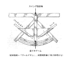
790,599号(これ以降「ゴールドマン」と言及される)に開示されている。従来の各種リクラインニングチェアは、座席に対してバックレストを傾斜させる機構を典型的に有している。多くは、またバックレストの動作の函数としてあるいは独立してかの何れかでレッグレストを上昇させるか、あるいは延長している。ゴールドマンにおいては、前記背面部、座部およびレッグレスト部は、(本図1に示すように)互いに固定的な構造的関係を有している。結果的に得られる調節可能なシート構造は、シートリクラインニング機構、即ち(本図2に示されるように)前記シートを各アームレストのおおよそのレベルにおいて位置するスイング旋回軸に結合する振り子アームを経由して支持構造体(外方のベースフレーム)の内側でスイングする。この構成を用いて且つ末端部のリクラインニング位置において、占有者は従来の各種リクラインニングチェアによって許可されたそれらよりもリラックスを達成するためのより好適な位置であると信じられる、心臓レベルよりそれらの足を上にしていた。
A chair intended to improve the biomechanics of seating is disclosed in U.S. Pat.
No. 790,599 (hereinafter referred to as "Goldman"). Various conventional reclining chairs typically include a mechanism for tilting the backrest relative to the seat. Many also raise or extend the leg rest either as a function of backrest motion or independently. In Goldman, the back, seat and leg rests have a fixed structural relationship to one another (as shown in FIG. 1). The resulting adjustable seat structure is via a seat reclining mechanism, i.e. a pendulum arm that couples the seat (as shown in FIG. 2) to a swing pivot located at the approximate level of each armrest. And swing inside the support structure (outer base frame). With this configuration, and in the terminal reclining position, the occupants are believed to be a better position to achieve relaxation than those permitted by the various conventional reclining chairs, from the heart level to those I was on my feet.
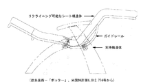
ゴールドマンからの発展は、本図3に示されるように、米国特許第6,012,774号(これ以降「ポッター」と言及される)に開示されている。主たる開発点は、チェアを作製すべく使用できる各タイプのデザインに関する。ポッターにおいて、前記シートをゴールドマンにおけるスイング旋回軸に結合する前記振り子アームは、この振り子アームが妨げになることができないため、実現できる各タイプのデザインを制限することが主張されている。ポッターにおいて、前記シートリクラインニング機構は、ゴールドマンにおける前記ピボットロケーションによって輪郭を定められる周囲に追従すべく形成されるガイドレールを含んでいる。このようにして、前記振り子アームが取り除かれる。 A development from Goldman is disclosed in US Pat. No. 6,012,774 (hereinafter referred to as "potter"), as shown in FIG. The main development point relates to each type of design that can be used to make a chair. In the potter, it is claimed that the pendulum arm, which couples the seat to the swing pivot in Goldman, limits the type of design that can be achieved, as this pendulum arm can not be impeded. In the potter, the sheet reclining mechanism includes guide rails formed to follow the perimeter delineated by the pivot location in Goldman. In this way, the pendulum arm is removed.
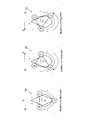
ゴールドマン及びポッターの双方において、物理的にあるいは仮想的に、シートリクラインニング機構は、リクライニング可能なシート構造の動きを決定する単一の固定の回転中心を有する。このことは、ヨーロッパ特許第0918480B1(これ以降「サムソン」として言及される)に記載されていうような各限界を有する。サムソンにおいて、そのような装置についての問題点は、(本図4に示されるように)少なくとも占有される場合、上方位置もしくは完全にリクラインニングした位置の何れかになる、リクライニング可能なシート構造の傾向性であることが主張される。これは、前記占有者と前記リクライニング可能なシート構造の組み合わされた質量中心が、これらの末端部の各位置から動くべく努力を要する中間位置よりもこれらの位置において低いためである。図4において、これは前記ガイドレールによって決定された仮想旋回軸点上に中心づけられた円によって例示されており、その周囲は質量中心を通過し、かくして質量中心のための運動経路を表す。サムソンにおいて、前記リクライニング可能なシート構造体は、本図5において示されるように前記シートリクライニング機構を形成する一対のスイングリンクによって前記支持構造体から吊るされている。前記リクライニング可能なシート構造を吊るす前記各スイングリンクのジオメトリは、前記リクライニング可能なシート構造と任意の占有者の組み合わされた質量中心が、前記チェアの移動の間略一定の高さで維持されているようである。 In both Goldman and Potter, physically or virtually, the sheet reclining mechanism has a single fixed center of rotation that determines the movement of the reclining seat structure. This has its limitations as described in European Patent 0 918 480 B1 (hereinafter referred to as "Samson"). In Samsung, the problem with such devices is that the reclining seat structure is at least either in the upper position or the fully reclined position (as shown in FIG. 4). It is asserted that it is a tendency. This is because the combined center of mass of the occupant and the reclineable seat structure is lower at these positions than at intermediate positions which require effort to move from their respective end positions. In FIG. 4 this is illustrated by a circle centered on an imaginary pivot point determined by the guide rails, the circumference of which passes through the center of mass and thus represents the movement path for the center of mass. In Samson, the reclineable seat structure is suspended from the support structure by a pair of swing links that form the seat reclining mechanism as shown in FIG. The geometry of each of the swing links hanging the reclining seat structure is such that the combined center of mass of the reclining seat structure and any occupant is maintained at a substantially constant height during the movement of the chair It seems to be.
サムソンにおける限界は、前記各スイングリンクが前記チェアを作製すべく使用できる各種のデザインを拘束することである。これは前記各スイングリンクを、(前記各アームレストのちょうど下の)前記支持構造の頂部から、前記シート構造から起立する振り子アームへ枢軸的に結合するためであり、それらのすべてが支障のないようにしなければならない。エントラップメントのリスクを回避すると共に、関連した各安全基準に合致するように、少なくとも前記各スイング結合は比較的に大きく且つ移動不能なアームレスト内に隠さなければならない可能性があり、そしてこのことは前記チェアの側から入口および出口を抑制することを可能にする。これは、固定レッグレストが前部から入ることおよび出ることを困難にするので、重要になる可能性がある。サムソンの他の限定は、スイング結合の使用が前記シートリクライニング機構のジオメトリを拘束することである。サムソンは最適なソリューションでない可能性がある前記各スイング結合によって決定される2個のアークに常に追従するであろう。
各リクライニング姿勢の生体力学を改善するため(ゴールドマン)、これらの各姿勢のために実現できる各種のデザインを改善するため(ポッター)、およびこれらの姿勢の間の遷移の容易さを改善するために(サムソン)、様々な努力がなされてきたことが、ここに報告された従来技術から理解することができる。従来技術を超えて発展させるために、実現可能である前記各種のタイプのデザインに関して柔軟性を可能にしながら、遷移の改善された容易さで同じ(もしくは類似の)各シートリクライニング姿勢を提供するシートリクライニング機構が望まれている。
The limitation in Samsung is to constrain the various designs that each of the swing links can use to make the chair. This is to pivotally couple the swing links from the top of the support structure (just below the armrests) to a pendulum arm standing up from the seat structure, all of which are non-disruptive It must be In order to avoid the risk of entrapment and to meet the relevant safety standards, at least the swing connections may have to be hidden in relatively large and immovable armrests, and this Makes it possible to restrain the entrance and the exit from the side of the chair. This can be important as it makes the fixed leg rest difficult to get in and out of the front. Another limitation of Samsung is that the use of a swing connection constrains the geometry of the seat reclining mechanism. Samsung will always follow the two arcs determined by each of the swing combinations which may not be the optimal solution.
To improve the biomechanics of each reclining position (Goldman), to improve the different designs that can be realized for each of these positions (Potter), and to improve the ease of transition between these positions (Samson) It can be understood from the prior art reported here that various efforts have been made. A seat that provides the same (or similar) seat reclining posture with improved ease of transition, while allowing flexibility with respect to the various types of designs that are feasible to advance beyond the prior art A reclining mechanism is desired.
本発明の第1の態様によれば、座席アセンブリ内で第2のアセンブリに対する第1のアセンブリの運動を制御するためのシートリクライニング機構が提供され、当該機構は:前記第1のアセンブリに取り付けるための第1および第2のベアリング手段と;前記第2のアセンブリに取り付けるためのハブとを含み;当該ハブは第1および第2の各傾斜面を含み、当該第2の各傾斜面は前記第1の傾斜面に対して対向的に面しており;使用に際して、前記第1のベアリング手段は前記第1の傾斜面に対して作用すべく配置され且つ前記第1の傾斜面に対しての前記第1のベアリング手段の相対的な位置は調節可能であり、そして前記第2のベアリング手段は前記第2の傾斜面に対して作用すべく配置され且つ前記第2の傾斜面に対しての前記第2のベアリング手段の相対的な位置は調節可能である。例えば、前記第1のベアリング手段は前記第1の傾斜面に沿って移動可能であり、そして前記第2のベアリング手段は前記第2の傾斜面に沿って移動可能であり(あるいは、代わりに、前記ベアリング手段は適位置に固定されていてもよく、そして前記ハブの各表面は前記ベアリングに対して可動であってもよい)。使用に際して、前記第1および第2のベアリング手段は双方共に前記第1のアセンブリに取り付けられ、それによって分離の固定距離において互いに結合されているので、前記ハブの前記第1および第2の各面に対する前記第1および第2のベアリング手段の移動は、前記第2のアセンブリに対する前記第1のアセンブリの回転を生じさせる。前記ハブの前記第1および第2の前記各傾斜面の配置および前記ハブの前記各面はカムのようなやり方で効率的に機能するように前記第1および第2のベアリング手段は前記第1および第2の前記各面に対して移動可能な方法とのおかげで、前記シートリクライニング機構を前記各姿勢の間の遷移の容易さを持つ各リクライニング姿勢の範囲を提供すべく使用できる。 According to a first aspect of the present invention there is provided a seat reclining mechanism for controlling movement of a first assembly relative to a second assembly in a seat assembly, said mechanism comprising: a mechanism for attaching to said first assembly First and second bearing means; and a hub for attachment to the second assembly; the hub includes first and second inclined surfaces, the second inclined surfaces being the first Facing oppositely to the first inclined plane; in use, said first bearing means are arranged to act against said first inclined plane and relative to said first inclined plane The relative position of said first bearing means is adjustable, and said second bearing means are arranged to act against said second inclined surface and relative to said second inclined surface Said second The relative position of the bearing means is adjustable. For example, the first bearing means may be movable along the first inclined surface, and the second bearing means may be movable along the second inclined surface (or alternatively, The bearing means may be fixed in place, and each surface of the hub may be movable relative to the bearing). In use, the first and second bearing means are both attached to the first assembly and are thereby joined together at a fixed fixed distance, so that the first and second faces of the hub are each The movement of the first and second bearing means with respect to Z causes rotation of the first assembly relative to the second assembly. The arrangement of the first and second inclined surfaces of the hub and the respective surfaces of the hub may function efficiently in a cam-like manner by the first and second bearing means. The seat reclining mechanism can be used to provide a range of reclined positions with ease of transition between the positions, thanks to the method movable relative to the respective second and third faces.
好ましい本実施の形態において、前記シートリクラインニング機構は、前記第1のアセンブリに取り付けるための第3のベアリング手段を更に含み、前記ハブは第3の面を含みそして、使用に際して、前記第3のベアリング手段は前記第3の面に対して作用すべく配置され、そして前記第3の面についての前記第3のベアリング手段の相対的な位置は可動的である(即ち、前記第2のアセンブリに対する前記第1のアセンブリの運動の間)。この第3のベアリング手段のおかげで、前記ベアリング手段すべてが前記ハブ上で保持することができ、かくして前記第1のアセンブリが使用の期間前記第2のアセンブリから着脱可能となることが防止される。 In a presently preferred embodiment, the sheet reclining mechanism further comprises third bearing means for attachment to the first assembly, the hub comprises a third surface and, in use, the third Bearing means are arranged to act against said third surface, and the relative position of said third bearing means with respect to said third surface is movable (i.e. relative to said second assembly) During the movement of the first assembly). By virtue of this third bearing means, all the bearing means can be held on the hub, thus preventing the first assembly from becoming removable from the second assembly for the duration of use .
前記ハブの前記第3の面は、前記ハブの略底部において存在する可能性がある。 The third surface of the hub may be present at approximately the bottom of the hub.
前記ハブの前記第3の面は、前記第3の面に対する前記第3のベアリング手段の相対的な移動の範囲を制限するための停止手段を組み込むことも可能であり、それによって前記第1のアセンブリが前記第2のアセンブリに対して移動可能である全体の量を限定する。ある実施の形態において、前記ハブの前記第3の面は、前記停止手段を組み込むように形が与えられる。 The third side of the hub may also incorporate stop means for limiting the range of relative movement of the third bearing means with respect to the third side, whereby the first Limiting the overall amount that the assembly can move relative to the second assembly. In one embodiment, the third side of the hub is shaped to incorporate the stopping means.
好ましい本実施の形態において、前記ハブの前記第1および第2の各面は、略直線的であると共に、逆向きの「V」字形を形成する。 In the preferred embodiment, the first and second faces of the hub are generally straight and form a reverse "V" shape.
前記ハブの前記第1の面および/もしくは第2の面は、例えば各種溝、各種凹部あるいは各窪みなどの表面の細部を組み込むことが可能であり、前記第2のアセンブリに対して1個もしくはそれ以上の所定の位置において前記第1のアセンブリをして可逆的に保持可能にする、および/もしくはユーザへの触覚フィードバックを与える(例えば、可能な移動の程度の終わりが近づいている時、各振動により指示する)。 The first and / or second side of the hub may incorporate surface details such as, for example, various grooves, various recesses or depressions, one or more for the second assembly Reversibly holding the first assembly in predetermined further positions and / or provide tactile feedback to the user (e.g. when the end of the degree of possible movement is approaching each Instructed by vibration).
好ましい本実施の形態において、前記各面は前記ハブの前記周囲に形成される。
しかしながら、代替的な各実施の形態において、前記各面は前記ハブの前記周囲の内側に形成されてもよい。
In a preferred embodiment, the faces are formed around the hub.
However, in alternative embodiments, the faces may be formed inside the periphery of the hub.
好ましい本実施の形態において、前記ハブは(例えば、鋼材あるいはある他の適切な物質から機械加工される)一体構造体として形成される。 In the preferred embodiment, the hub is formed as a unitary body (eg, machined from steel or some other suitable material).
しかしながら、他の各実施の形態において、前記ハブは、前記各面の1個もしくはそれ以上が1個のハブコンポーネントによって提供され、そして前記各面の1個もしくはそれ以上の他のものは1個もしくはそれ以上の他のハブコンポーネントによって提供されるように、複数のハブコンポーネント(例えば、個別的な空間的に分離されたコンポーネント)を含んでいてもよい。 However, in each of the other embodiments, the hub is provided that one or more of the faces are provided by a single hub component, and one or more of the other ones of the faces are provided. A plurality of hub components (e.g., discrete spatially separated components) may be included, as provided by other hub components or more.
本発明の第2の態様によれば、本発明の第1の態様に従った1個もしくはそれ以上のシートリクラインニイグ機構を含む座席アセンブリが提供される。前記あるいは各シートリクラインニイグ機構に関して、前記第1のベアリング手段は、前記第1の傾斜面に対して作用するように配置され且つ前記第1の傾斜面に対する前記第1のベアリング手段の相対的な位置は調整可能であり、そして前記第2のベアリング手段は、前記第2の傾斜面に対して作用するように配置され且つ前記第2の傾斜面に対する前記第2のベアリング手段の相対的な位置は調節可能である。 According to a second aspect of the present invention there is provided a seat assembly comprising one or more seat reclining nigs in accordance with the first aspect of the present invention. With respect to the or each seat reclining mechanism, the first bearing means is arranged to act against the first inclined surface and relative to the first inclined surface with respect to the first bearing means. Position is adjustable, and the second bearing means is arranged to act against the second inclined surface and relative to the second bearing means with respect to the second inclined surface. The position is adjustable.
好ましい本実施の形態においては、前記座席アセンブリは、前記各シートリクラインニイグ機構の2個、すなわち当該座席アセンブリの各側面に1個を含んでいる。 In the preferred embodiment, the seat assembly includes two of the respective seat reclining nigs, one on each side of the seat assembly.
好ましい本実施の形態においては、前記もしくは各シートリクラインニイグ機構に関して:前記第1および第2のベアリング手段が取り付けられている前記第1のアセンブリは、リクライニング可能なシート構造体であり;前記ハブが取り付けられている前記第2のアセンブリは、前記リクライニング可能なシート構造体のための支持構造体であり;当該リクライニング可能なシート構造体は、前記各面に沿って前記ベアリング手段の移動によってリクライニングするやり方で前記支持構造体に対して移動することが可能である。 In a preferred embodiment, with respect to the or each seat reclining mechanism: the first assembly on which the first and second bearing means are mounted is a reclineable seat structure; the hub Said second assembly to which is attached is a support structure for said reclineable seat structure; said reclining seat structure reclining by movement of said bearing means along said respective faces It is possible to move relative to the support structure in a manner that
しかしながら、ある代替的な実施の形態において、前記もしくは各シートリクラインニイグ機構に関して:前記ハブが取り付けられている前記第2のアセンブリはリクライニング可能なシート構造体であり;前記第1および第2のベアリング手段が取り付けられている前記第1のアセンブリは、前記リクライニング可能なシート構造体のための支持構造体であり;当該リクライニング可能なシート構造体は、前記ベアリング手段の前記各位置に対して前記ハブの回転によってリクライニングするやり方で前記支持構造体に対して移動することが可能である。 However, in an alternative embodiment, with respect to the or each seat reclining mechanism: the second assembly on which the hub is mounted is a reclineable seat structure; said first and second The first assembly to which the bearing means is attached is a support structure for the reclineable seat structure; said reclining seat structure being said relative to said respective positions of said bearing means. It is possible to move relative to the support structure in a reclining manner by rotation of the hub.
前記座席アセンブリは、例えば、1個もしくはそれ以上のスプリングピンなどの直接ロッキングデバイスや、あるいは遠隔作動型リリースを備えたガススプリングなどの遠隔ロッキングデバイスなどの前記支持構造体に対して前記リクライニング可能なシート構造体の角度を可逆的に保証するための手段を更に含んでいる。 The seat assembly may be reclineable relative to the support structure such as, for example, a direct locking device, such as one or more spring pins, or a remote locking device, such as a gas spring with a remotely actuated release. It further comprises means for reversibly securing the angle of the sheet structure.
リクライニング可能なシート構造の構成に関して、好ましい本実施の形態において、これは背面部と、座部と、随意的にレッグレストとを含む。前記背面部および前記座部は、互いに構造的に固定可能であるか、あるいは互いに相対的に調節可能である。同様に、(もし存在するならば)前記レッグレスト部は前記座部に互いに構造的に固定可能であるか、あるいは一定の調節可能な角度であることもできる。 With regard to the configuration of the reclineable seat structure, in the presently preferred embodiment, this includes the back, the seat and optionally the leg rest. The back and the seat may be structurally fixable to one another or may be adjustable relative to one another. Similarly, the leg rests (if present) may be structurally fixable to one another at the seat or may be at an adjustable angle.
前記支持構造体に関して、好ましい本実施の形態において、これは台座ベースおよび随意的に旋回軸(例えば、メモリリターンスピンドル)も具備している。 With respect to the support structure, in the presently preferred embodiment, it also comprises a pedestal base and optionally a pivot (e.g. a memory return spindle).
前記座席アセンブリは、シートリクライニイグ機構の動作に依存して、移動するよう構成された1個もしくはそれ以上の可動部を更に含んでいてもよく、前記各可動部は、例えば、1個もしくはそれ以上の伸縮自在のレッグレスト、(前記シートに対してリクライニイグ可能な)リクラインニイグバックレスト、ヘッドレスト/バックレスト関節部、あるいは折り畳み式アームレストである。 The seat assembly may further include one or more moveable parts configured to move depending on the operation of the seat reclining mechanism, each moveable part being, for example, one or more. Further telescopic leg rests, reclining lug rests (recreasable for the seat), headrest / back rest joints or foldable arm rests.
本発明の第3の態様によれば、座席アセンブリ内の第2のアセンブリに対する第1のアセンブリの運動を制御する方法が提供され、当該方法は第1および第2のベアリング手段を前記第1のアセンブリに取り付け;ハブを前記第2のアセンブリへ取り付け;ここで前記ハブは第1および第2の傾斜面を含み、当該第2の傾斜面は前記第1の傾斜面に対して対向的に面しており;前記ハブの前記第1の傾斜面に対して作用すべく前記第1のベアリング手段を配置し;前記ハブの前記第2の傾斜面に対して作用すべく第2のベアリング手段を配置し;前記ハブの前記第1の傾斜面に対する前記第1のベアリング手段の相対的な位置を調整し;前記ハブの前記第2の傾斜面に対する前記第2のベアリング手段の相対的な位置を調整する方法。 According to a third aspect of the present invention there is provided a method of controlling movement of a first assembly relative to a second assembly in a seat assembly, the method comprising first and second bearing means Mounting on an assembly; mounting a hub on the second assembly; wherein the hub includes first and second sloped surfaces, the second sloped surface being opposite to the first sloped surface Arranging the first bearing means to act against the first inclined surface of the hub; and second bearing means to act against the second inclined surface of the hub. Arranging the relative position of the first bearing means to the first inclined surface of the hub; adjusting the relative position of the second bearing means to the second inclined surface of the hub How to adjust.
前記ハブは、第3の表面を更に含んでいてもよい、そして前記方法は第3のベアリング手段を前記第1のアセンブリに取り付け;前記ハブの前記第3の表面に対して作用すべく前記第3のベアリング手段を配置し、(即ち、前記第2のアセンブリに対する前記第1のアセンブリの運動の間)前記ハブの前記第3の表面に対する前記第3のベアリング手段の相対的な位置を変化させることを含む。更にまた、前記方法は前記第3の面に対する前記第3のベアリング手段の相対的な移動の範囲を制限することを含んでもよい。 The hub may further include a third surface, and the method attaches a third bearing means to the first assembly; the third to act against the third surface of the hub. Placing three bearing means (i.e. during movement of the first assembly relative to the second assembly) changing the relative position of the third bearing means with respect to the third surface of the hub Including. Furthermore, the method may comprise limiting the range of relative movement of the third bearing means with respect to the third surface.
前記方法は、前記第1のアセンブリを前記第2のアセンブリに対して1個あるいはそれ以上の所定の位置において保持させるようにおよび/もしくは前記ユーザの触覚フィードバックを与えるように、前記ハブの前記第1の面および/もしくは前記第2の面における各溝、各凹部、および各窪みなどの表面細部を組み込むことを更に含んでもよい。 The method may include holding the first assembly at one or more predetermined positions relative to the second assembly and / or providing haptic feedback of the user on the hub. It may further include incorporating surface details such as each groove, each recess, and each recess in one surface and / or said second surface.
好ましい本実施の形態において、前記第1のアセンブリはリクライニング可能なシート構造体であり、前記第2のアセンブリは前記リクライニング可能なシート構造体のための支持構造体であり、前記方法は前記各表面に沿って前記ベアリング手段の移動によってリクラインィングするやり方で前記支持構造体に対して前記リクライニング可能なシート構造体を移動させることを更に含む。 In a preferred embodiment, the first assembly is a reclineable seat structure and the second assembly is a support structure for the reclineable seat structure, the method comprising the steps of: And moving the reclineable seat structure relative to the support structure in a reclining manner by movement of the bearing means along.
しかしながら、代替的な実施の形態において、前記第2のアセンブリはリクライニング可能なシート構造体であり、前記第1のアセンブリは前記リクライニング可能なシート構造体のための支持構造体であり、前記方法は:前記ベアリング手段の前記各位置に対して前記ハブの回転によりリクラインニングするやり方で前記支持構造体に対して前記リクライニング可能なシート構造体を移動することも更に含む。 However, in an alternative embodiment, the second assembly is a reclining seat structure, the first assembly is a support structure for the reclining seat structure, and the method comprises Moving the reclineable seat structure relative to the support structure in a manner to reline by rotation of the hub relative to each position of the bearing means.
前記方法は前記支持構造体に対して前記リクライニング可能なシート構造体の角度を可逆的に保証することを更に含んでもよい。 The method may further include reversibly securing the angle of the reclineable seat structure relative to the support structure.
上記のシートリクラインニング機構の好ましい本実施の形態において、座席アセンブリあるいは方法、前記ベアリング手段およびハブは、図8にあるいは図9において例示されたジオメトリに従って互いに相対的に移動するよう好ましく構成される。 In the preferred embodiment of the above seat reclining mechanism, the seat assembly or method, the bearing means and the hub are preferably arranged to move relative to one another according to the geometry illustrated in FIG. 8 or in FIG.
本発明の各実施の形態は、例によってのみ、そして添付図面を参照して記載されるであろう。
各本実施の形態は、本発明を実施する出願人にとって公知の最良の各方法を表している。しかしながら、それらはこれを得ることができる唯一の方法ではない。 Each of the present embodiments represents the best way known to the applicant for practicing the present invention. However, they are not the only way to get this.
各本実施の形態は、シートリクライニング機構によって要求される空間を最小に維持しつつ、改善された着座生体力学および運動制御を目的とした調節可能な各種チェアのために開発されてきた。好ましい各実施の形態は中心ハブの周囲で並進する3個のローラベアリングを含むシートリクライニング機構を提供する。当該各ローラベアリングは前記リクライニング可能なシート構造体に対して固定されてもよく、そして前記ハブは前記支持構造体に対して固定されていてもよい。前記ハブの周囲の形状および前記リクライニング可能なシート構造体に対するその位置は、前記チェアの運動経路およびそのバランスを決定する。 Each of the present embodiments has been developed for a variety of adjustable chairs for improved seating biomechanics and motion control, while keeping the space required by the seat reclining mechanism to a minimum. The preferred embodiments provide a seat reclining mechanism that includes three roller bearings that translate around a central hub. The respective roller bearings may be fixed relative to the reclining seat structure and the hub may be fixed relative to the support structure. The peripheral shape of the hub and its position relative to the reclining seat structure determine the movement path of the chair and its balance.
以下のチェアデザインは例によってのみ与えられ、そして限定するものではない。本例においては、前記背面部、座部およびレッグレスト部が固定された構造的な関係を有するようにゴールドマン、ポッターおよびサムソンによって開示された前記チェアの一般的な構成が続く。 The following chair designs are given by way of example only and are not limiting. In the present example, the general configuration of the chair disclosed by Goldman, Potter and Samson follows, so that the back part, the seat part and the leg rest part have a fixed structural relationship.
図6は本発明を具体化するリクライニングチェア10を例示する。このチェアは、背面部12、座部14およびレッグレスト部16を含む。一緒に、前記背面部12、座部14およびレッグレスト部16はリクライニング可能なシート構造体18を形成する。当該リクライニング可能なシート構造体18は支持構造体20(この場合、外方のベースフレーム)内において可動である。本発明の一実施の形態によれば一対のシートリクライニング機構30は、前記リクライニング可能なシート構造体18と前記支持構造体20との間のインターフェースにおいて、一般的に前記チェアの各側部における前記アームレスト22の下方に設けられている。言い換えるならば、一方のシートリクライニング機構30は前記チェアの一方の側に設けられており、そして他方のシートリクライニング機構30は前記チェアの他方の側に設けられている。なお図6において前記シートリクライニング機構30のリーダの視野が支持構造体20によって不明瞭にならないように、前記チェアの各側部が部分的に透き通るようなやり方で示されていることに注目すべきである。
FIG. 6 illustrates a
本例において、前記チェア10の一般的な構成は、前記リクライニング可能なシート構造体18が各製品の範囲を達成する種々の方法において製造できるようにモヂュールとなっている。各例は、布張バージョン、CNC木材フレームバーション、加圧積層合板バーション、およびコールドモールドポリカルボネートバーションを含む。
In this example, the general configuration of the
本例においては、前記支持構造体20は、「U」字型の形状を創るために形成されたフラットスチールから製造され、そして旋回機能を与えるスターベース26の上に位置したメモリリターンスピンドル24に着座している。前記支持構造体20は、各種チェアモデルの範囲にわたる標準的なコンポーネントであってもよい。同様に、前記スピンドル24およびスターベース26は、各種チェアモデルの範囲にわたる標準的なコンポーネントであってもよい。当業者が認識するように、前記支持構造体20の各半径およびその一般的な各比率であるように、各スピンドルおよび各ペデスタルベースの他の各形状および各構成はもちろん可能である。
In the present example, the
図7に示されるように、遠隔油圧ボタンリリース29付の市販のロック可能なガススプリング28は、前記チェアを解除可能にロックすべく、(即ち、前記ベースに対して前記リクライニング可能なシート構造体の角度を解除可能にロックすべく)、そしてそれが移動するように前記リクライニング可能なシート構造体18の加速を減衰させるべく、採用されてもよい。ある幾つかの実施の形態において、ロック可能あるいはそうでなければ、前記チェアの他方の側に第2のガススプリングを有することもまた好ましい可能性がある。ロックすることおよび減衰させることの2つの機能は1つのコンポーネント内で示唆されるけれども、当該各機能はロックすることのみに特定された、前記チェアの一方の側の専用のダンパー、そして前記チェアの他方の側のガススプリングなどの、2個のコンポーネントに分離しようとすればそれも可能である。任意の観点で、ロック可能なガススプリングは使用の2つのモードを可能にする。すなわち、 (1)前記ボタン29は、前記リクライニング可能なシート構造体18を移動させるべく手動で押さえつけられなければならないと共に当該ボタン29のクイックリリースが前記チェアを剛体的にロックするアクティブリクライニングモード;および(2)前記ボタンを押圧しない連続運動のためのパッシブリクラインニングモードがある。使用の当該2つのモードは、種々の方法で達成可能である。例えば、前記リリースボタン29は、前記ボタンのストロークの約半分押下する際ガススプリングの作動を可能にするが、解除された際、反対にロックすべく跳びはねるばね機構を持っていてもよい。これは、使用のアクテイブモードを達成するであろう。前記パッシブモードにとって、解除された時、それがスプリングバックしないように前記ボタンをその程度押圧することは当該ボタンを適位置にクリックして、そして前記ガススプリングをロックすることが可能である。そのようなボタン機構は次いで力の第2の印加を要求して前記ボタンを拡張された位置まで復帰させることが可能である。油圧およびワイヤ型ボタンリリース機構の双方は、1個もしくはそれ以上のガススプリングを制御するための複数のボタンを許可する各接続部を用いて実行可能である。そのような機構を用いて、標準的なボタンリリースは、前記アクテイブリクライニングモードにとって使用すればそれも可能であり、そして第2のボタンは、上述したように、その程度まで押圧する際、クリックして固定位置になる前記チェア上のより分離したロケーションにおいて利用することが可能と言えばそれも言える。前記チェアをロックするためのガススプリング28を使用する付加的な恩恵は、前記ボタン29をどこに位置させるかに関しての制約が実際上存在しないということである。(実際、ポッターは、ゴールドマンにおけるブレーキアセンブリのための操作レバーが前記チェア上のそのロケーションに起因して部分的に使用するには扱いにくいと説明している。)
As shown in FIG. 7, a commercially available
前記シートリクラインニング機構30およびその動作は、より詳しく記載されるであろう。
The
シートリクラインニング機構 Seat reclining mechanism
前記シートリクライニング機構30のデザインの目的は、使用に際して、(例えば、リクライニング運動あるいは直立運動の間)、任意の占有者にとって質量中心(COM)用の略水平な運動経路となる前記リクライニング可能な機構18用の運動経路を達成することである。この目的はサムソンにおけるそれと類似している。使用中、前記COM用水平な運動経路を持つことによって、チェアはユーザにとってバランスがとれた感じとなり、そしてユーザの方では、最小の労力で使用することが簡単である。このCOMは、ユーザのみならず前記リクライニング可能なシート構造体18の質量を含んでおり、そしてその運動は発明者によって刊行された生体力学モデルの開発を用いてシュミレートされてきた(Wickett, D. H. 2013, リクライニングされた着座姿勢の生体力学モデルの開発、検証、および応用、博士論文、アングリアラスキン大学、ケンブリッジ、英国)。前記生体力学モデルを本シートリクラインニング機構の好ましい実施の形態に適用すると、50番目のパーセントタイルの女性の人体計測モデルのCOMのための運動経路は、5番目および95番目の男性の各モデルにとって水平からの最小変動が付加的な各胸部負荷を含んだ状態で、前記シートの移動の間完全に水平のままであることが判明した。
The purpose of the design of the
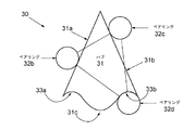
図6乃至9を参照して、各シートリクラインニング機構30は、中心ハブ31と、当該ハブ31の周囲で並進することができる少なくとも2個のベアリングコンポーネント32(本例では、各ローラベアリング)とを含んでいる。好ましい本実施の形態では、前記リクラインニング可能なシート構造体18(例えば、前記各ベアリングスタッドを受けるためのテーパ付の各孔を備えた機械加工された各スチールボス)の前記各外方面において、それらを対となった各コンポーネント内に螺子込ませる各スタッドを、前記各ローラベアリング32は有する。(前記各本例において、機械加工されたスチールコンポーネントである)前記ハブ31は、前記支持構造体20の内方に面する面に固定されている。
6 to 9, each
図6乃至9から認識されるように、前記ハブ31の周囲の前記断面形状は円形状ではない。図6乃至9に示される各本実施の形態において、前記ハブ31の周囲の断面形状は、他の各実施の形態において、これはその場合に必ずしも必要でないけれども、垂直な軸の回りの鏡面対称性を有している。例を用いて図9を参照し、前記ハブ31の周囲は、その上で前記上方の2個の負荷軸受用ローラベアリング32b, 32cが夫々作用する(1個のローラベアリングが各傾斜した上面の各々の上で作用する)2個の対向的に面し、上方に面する傾斜した(例えば対角的に配向される)各面31a,31bを有する。そのように行う際、前記上方の2個のローラベアリング32b, 32cは、前記ハブ31を経由して、前記ベース20へ下方に前記リクライニング可能なシート構造体18(および前記ユーザ)の重量を伝達する。
As will be appreciated from FIGS. 6-9, the cross-sectional shape around the
当業者が認識するように、前記ハブ31は前記各ローラベアリング32b, 32cが前記カムの前記各傾斜面に作用した状態で、効果的にカムとして作用する。
As those skilled in the art will appreciate, the
各本実施の形態において、前記ハブ31の周囲の各傾斜面31a,31bは、当該各傾斜面31a,31bが頂部あるいは丸くされた先端部において合致した状態で、反転した「V」字形状を略形成する。しかしながら、代替的な各実施の形態において、1個もしくはそれ以上の他の面は、前記各傾斜面31a,31bの間に挟まれてもよい。そのような代替的な各ジオメトリの幾つかの例は、図10(a)および10(b)に示される。これらの例示の各々において、前記各ベアリングは前記各円によって描写され、そして前記ハブは他の形によって描写される。図10(a)は、その上で前記各ベアリングが作用する前記2個の傾斜面の間に挟まれた平坦面を例示し、図10(b)は、その上で前記各ベアリングが作用する前記2個の傾斜面の間に挟まれた曲面を例示する。
In each of the present embodiments, the
各本実施の形態において、前記ハブ31は(例えば、スチールあるいはある他の適切な物質から機械加工された)一体構造体として形成される。しかしながら、他の各実施の形態において、前記各ベアリング面の1個もしくはそれ以上が1個のハブコンポーネントによって提供され、そして前記各ベアリング面の1個もしくはそれ以上の他のものが1個もしくはそれ以上の他のハブコンポーネントによって提供されるように、前記ハブ31は複数のハブコンポーネント(例えば、個別的で空間的に分離した各コンポーネント)を含んでもよい。
In each of the present embodiments, the
そのような配列の幾つかの例は、各図10(c)および10(d)、更に各図11(a)および11(b)において示されている。図10(c)は、2個の空間的に分離されたハブコンポーネントを例示している。(各円によって描写される)2個のベアリングは、各ベアリングが(その他の形状によって描写される)各ハブコンポーネントの傾斜した上面に作用した状態で、前記ハブに対して作用する。図10(d)は、2個の空間的に分離されたハブコンポーネントをまた含むハブと、当該ハブに対して作用するが、各ベアリングが(その他の各形状によって描写される)各ハブコンポーネントの傾斜した内面に作用した状態で、(各円によって描写される)2個のベアリングとを備えた異なった配列を例示している。 Some examples of such arrangements are shown in each of Figures 10 (c) and 10 (d), and further in each of Figures 11 (a) and 11 (b). FIG. 10 (c) illustrates two spatially separated hub components. Two bearings (depicted by each circle) act on the hub with each bearing acting on the inclined upper surface of each hub component (depicted by the other shape). FIG. 10 (d) shows a hub which also comprises two spatially separated hub components and which acts on the hub, but in which each bearing (depicted by each other shape) Fig. 6 illustrates a different arrangement with two bearings (depicted by each circle), acting on an inclined inner surface.
図11(a)において、前記ハブは3個の空間的に分離されたハブコンポーネントを例示している。(各円によって描写される)3個のベアリングは、各ベアリングが(その他の各形状によって描写される)各ハブコンポーネントの傾斜した外方面に作用した状態で、前記ハブに対して作用する。図11(b)は、3個の空間的に分離されたハブコンポーネントを再び含むハブと、当該ハブに対して作用するが、各ベアリングが(その他の各形状によって描写される)各ハブコンポーネントの内面に作用する(各円によって描写される)3個のベアリングとを備えた異なった配列を例示している。 In FIG. 11 (a), the hub illustrates three spatially separated hub components. Three bearings (depicted by each circle) act on the hub with each bearing acting on the inclined outer surface of each hub component (depicted by each other shape). FIG. 11 (b) shows the hub again comprising three spatially separated hub components and, for each hub component acting on the hub, each bearing (depicted by each other shape) Fig. 7 illustrates a different arrangement with three bearings (depicted by each circle) acting on the inner surface.
(例えば、各図6−9に示されるような)好ましい本実施の形態において、前記各負荷軸受用ローラベアリング32b, 32cの各々は、使用際して、前記ハブ31の周囲の前記各傾斜上面31a, 31bの略全長に沿って移動することができる。しかしながら、これがその場合ではない他の各実施の形態も考えることが可能である。
In the presently preferred embodiment (as shown, for example, in each of FIGS. 6-9), each of the load bearing roller bearings 32b, 32c, when in use, each of the inclined top surfaces around the
好ましい各本実施の形態において、前記ハブ31の周囲の各傾斜上面31a, 31bの各々は、スムーズで単様なジオメトリ(例えば、線状のプロファイルもしくは、代替物として、スムーズで単様な曲線)を有し、前記各ローラベアリングのスムーズな並進かくして前記シートの角度のスムーズな調節を可能にする。しかしながら、各代替的な実施の形態において、前記ハブ31の周囲の各傾斜上面31a, 31bは、1個もしくはそれ以上の留め金あるいは各他の凹凸部を備えて、例えば、使用に際して前記各ベアリング32b, 32cの並進運動を調節してもよい。例えば、そのような各留め金は、リクラインニング運動の前、その間あるいはその後に、前記シート角度が保留されるであろう1個もしくはそれ以上の位置を決定することを可能にする。そのような位置において保留される場合、ユーザの重量あるいは幾らかの他の力(実際には、比較的わずかな力)の印加の再分散は、前記留め金の効果に打ち勝つことを要求され、それによって前記シートの角度の更なる調節を可能にするだろう。
In each preferred embodiment, each of the inclined
随意的に、例えば、各図6−9に示されるように、前記ハブ31の周囲の下面31cに対して作用し、前記ハブ31上のすべての前記各ベアリング32b, 32c, 32dを保持し(それによって使用の間前記各リクラインニング可能なシート構造体18が前記支持構造体20から取り外し可能となることが防止され)および/もしくは前記シートの角度の調節の範囲を限定する、第3のローラベアリング32dが提供されてもよい。アセンブリにとって、第3の(即ち、最も低い)ローラベアリング32dは、前記各ローラベアリング32と前記ハブ31との間の許容度を減少させる調節を有する。
Optionally, it acts against the
その上で前記ローラベアリング32dが作用する前記ハブ31の前記下面31cは、各図6, 7および9に示されるように輪郭が描かれ、前記シートの角度の調節の全体の範囲を限定するように、各端部においてストップ33a, 33bを効果的に組み込んでもよい。
The
図8は、各本実施の形態が導出されるジオメトリを示している。当該ジオメトリは、側面図における予測されたCOMロケーションにおいて位置する水平なベースと、上方の頂点を備えた2等辺3角形に基づいている。各頂点A, B, C, Dおよび前記リクラインニング可能な構造体は、固定された幾何学的関係を有している。各頂点 B, C, Dは、前記各ローラベアリング(32b,32c,32d)のためのロケーションを表現し、更に頂点Aは前記COMのロケーションを表現する。各頂点 B, Cは、前記リクラインニング可能なシート構造体18および占有者の運動経路を定義する前記2等辺3角形の各脚部に沿って移動すべく拘束されている。頂点Dは、BとCによって定義される前記軌跡に拘束される。頂点Dにおける前記ローラベアリング(32d)の目的は、すべてのローラベアリング(32b,32c,32d)および前記ハブ31に対する前記リクラインニング可能なシート構造体18をロックすることである;BとCからのその距離は任意である。
FIG. 8 shows the geometry from which each of the present embodiments is derived. The geometry is based on an isosceles triangle with a horizontal base located at the predicted COM location in the side view and an upper vertex. Each vertex A, B, C, D and the recorable structure have a fixed geometrical relationship. Each vertex B, C, D represents a location for each roller bearing (32b, 32c, 32d), and a vertex A represents a location of the COM. Each vertex B, C is constrained to move along each leg of the reclosable seat structure 18 and the legs of the isosceles triangle defining the occupant's motion path. The vertex D is constrained to the trajectory defined by B and C. The purpose of the roller bearings (32d) at the apex D is to lock all the roller bearings (32b, 32c, 32d) and the recinable sheet structure 18 to the
図9は、運動の範囲を限定すべく図8に示される前記ジオメトリを拡張している。ここで、頂点Dを拘束する前記ハブ31のベースにおける曲線は、前記チェアの各所望の末端位置における前記ベアリング32dを停止すべく、修正される。
FIG. 9 extends the geometry shown in FIG. 8 to limit the range of motion. Here, the curve at the base of the
三角形ABCの比率が図8に示されるような構成概念上の三角形と同じであると仮定すると、前記予測されたCOM(頂点A)は完全に水平に並進するであろう。前記構成概念上の2等辺三角形の形状および三角形ABCのサイズは、前記アームレストの存在、前記各ベアリングのサイズ、及び美的な各要求などの前記チェアの各物理的拘束条件によって影響を受けるであろう。頂点Aにおける角度および三角形ABCの高さを増加させることは、前記COMが移動する距離を増加するだろう、そして前記チェアの安定性に影響を与えるであろう。 Assuming that the ratio of triangle ABC is the same as the constructive triangle as shown in FIG. 8, the predicted COM (apex A) will translate completely horizontally. The geometry of the isosceles triangle and the size of the triangle ABC on the construct will be influenced by the physical constraints of the chair such as the presence of the armrest, the size of the bearings and the aesthetic requirements. . Increasing the angle at vertex A and the height of triangle ABC will increase the distance traveled by the COM and will affect the stability of the chair.
かくして、図8において示される例において、各頂点BおよびCは前記構成概念上の2等辺3角形の前記各脚部に沿って移動するように拘束されている。頂点Aは、前記三角形ABCの比率が前記構成概念上の三角形と同じであると仮定すると、水平方向に常に並進するであろう。頂点Dのための軌跡は、各頂点BおよびCによって決定される。頂点Dと各頂点BおよびCとの間の距離は任意である。各頂点 B, C, Dは、前記各ベアリング(32b,32c,32d)の位置を決定し、そして頂点Aは、前記リクラインニング可能な構造体と占有者の質量中心を表現する。前記ハブ31のジオメトリは、前記各ベアリングの各軌跡から決定されてもよい。
Thus, in the example shown in FIG. 8, the vertices B and C are constrained to move along the legs of the constructive isosceles triangle. The vertex A will always translate horizontally, assuming that the ratio of the triangle ABC is the same as that of the constructive triangle. The trajectory for vertex D is determined by each vertex B and C. The distance between vertex D and each vertex B and C is arbitrary. Each vertex B, C, D determines the position of each said bearing (32b, 32c, 32d), and vertex A represents the center of mass of the recyclable structure and the occupant. The geometry of the
図8および9に示される前記各ジオメトリは、前記目的物が水平に並進すべく前記予測されたCOMに対するものであった各例である。他の各デザインにおいて、水平なCOM運動経路を有さないことが望ましい可能性もある。前記ハブは自由な形状であるので、ほとんど任意の軌跡を定義することが可能である。例えば、その中間点あるいは末端位置(複数も可)に向けて前記COM運動経路に斜面を設けることも望ましい可能性がある。 The geometries shown in FIGS. 8 and 9 are examples for the predicted COM to translate the object horizontally. In each other design, it may be desirable not to have a horizontal COM motion path. Because the hub is free-form, it is possible to define almost any trajectory. For example, it may be desirable to have the COM motion path beveled towards its midpoint or end position (s).
各図6, 7および8(a)に示されるように、好ましくは、前記上方の各ローラベアリング(32b, 32c)は、前記チェアが中間のリクラインニング位置にある時、前記ハブ31に関して略水平な関係にある。この位置から、前記チェアが図8(b)に示されるような直立あるいは前方内へ移動する場合、前記最も前方の上方のローラベアリング(32c)は、前記ハブ31のその各傾斜面(31b)を下方に移動し、前記最も後方の上方のローラベアリング(32b)は、前記ハブ31のその各傾斜面(31a)を上方に移動する。逆に、図8(a)の中間リクラインニング位置から始めて、前記チェアが図8(c)に示されるような最大リクラインニング位置内に移動する場合、前記最も前方の上方のローラベアリング(32c)は、前記ハブ31のその各傾斜面(31b)を上方に移動し、そして前記最も後方の上方のローラベアリング(32b)は、前記ハブ31のその各傾斜面(31a)を下方に移動する。図示するように、前記リクラインニング動作と直立動作との双方の間、前記COMは略水平に移動し、そしてその結果前記チェアは前記ユーザにとってはバランスがよく感じられ、そして前記ユーザの方で最小の努力で使用することは簡単である。
Preferably, as shown in the respective FIGS. 6, 7 and 8 (a), the upper roller bearings (32b, 32c) are substantially horizontal with respect to the
使用の方法 Method of use
再び、図6および7を参照して、使用に際して、ユーザは、それらの底部を前記座部14に、それらの背面を前記背面部12に対するように、そしてそれらのふくらはぎを前記レッグレスト部16に対するようにして、前記チェア10のリクラインニング可能なシート構造体18上に着座する。それらは、一つが含まれている場合に、ヘッドレストにそれらの頭部を休ませることも可能である。
Referring again to FIGS. 6 and 7, in use, the user places their bottom on the
単に、それらのCOMを後方に移動する前記ユーザによって(例えば、前記各アームレストに対して押圧し、姿勢を変化させ、および/もしくは筋肉の様子を変化させることによって)、そして任意の固定機構(例えば、上記に記載したロック可能なガススプリング28)を解除して、前記リクラインニング可能なシート構造体18が後方にリクラインニングするだろう。逆に、前記リクライニング可能なシート構造体18はリクラインニングされた位置にある時、前記COMを前方に単に移行させることは(例えば、前記アームレストをプル・オンし、姿勢を変化させ、および/もしくは筋肉の様子を変化させることは)、前記リクライニング可能なシート構造体18をして、再び任意のロッキング機構を解除した状態で、直立位置に向けて復帰させられるであろう。
Simply by the user moving their COM backwards (eg, by pressing against each armrest, changing posture, and / or changing the appearance of muscles), and any fixation mechanism (eg, The
任意の点において、前記ユーザは、前記ロック可能ガススプリング28あるいは他のロッキング機構を用いて、前記リクライニング可能なシート構造体18の傾きの角度を解除可能にロックすることが可能である。その代わりに、全体的に自由な移動にとって、前記ロッキング機構は全体として解除可能であり、あるいは最初は設けられていなくともよい。
At any point, the user can releasably lock the tilt angle of the reclineable seat structure 18 using the
好ましい本実施の形態において、上記で記載したように前記水平なCOM運動経路のおかげで、使用に際して、前記チェアおよび前記ユーザはよくバランスしていると感じられ、そして前記リクライニング(あるいは直立)動作は、前記ユーザの方で最小限の努力で行うことは簡単である。 In the preferred embodiment, the chair and the user are perceived as well-balanced in use by virtue of the horizontal COM motion path as described above, and the reclining (or upright) motion is It is easy to do with minimal effort on the part of the user.
可能な各修正例および各代替的な実施の形態 Possible modifications and alternative embodiments
幾らかの可能な各修正例および各代替例と一緒に、詳細な各実施の形態が上記で記載されてきた。当業者が認識するように、本明細書において具体化された前記各発明からなお恩恵を受けつつ、数多くの付加的な修正例および各代替例が成され得る。 Detailed embodiments have been described above, along with some possible modifications and alternatives. As those skilled in the art will appreciate, numerous additional modifications and alternatives can be made while still benefiting from the above-described inventions embodied herein.
例えば、所定の各位置において(例えば、直立、中間リクラインニングおよびフルリクラインニングの各姿勢において)前記リクラインニング可能なシート構造体を保持することおよび/もしくは改善された位置センスのための触覚フィードバック(例えば、前記各末端位置に向けて一緒に密になる各窪み)を与えるために、前記各ベアリング面における各溝あるいは各窪みなどの、前記ハブに対する更なる各修正は望ましい可能性がある。代替的な各ロッキングシステムは、前記ベアリング位置を固定する遠隔リリースを備えたスプリングピンなどの、前記シートリクラインニング機構内へ直接組み込もうとすればそれも可能である。 For example, tactile feedback for holding and / or improved position sensing of the recorable sheet structure at each predetermined position (e.g., in upright, intermediate reclining and full reclining postures) For example, each further modification to the hub, such as each groove or each recess in each bearing surface, may be desirable to provide each recess densely packed towards each end position. Each alternative locking system could also be incorporated directly into the seat reclining mechanism, such as a spring pin with a remote release securing the bearing position.
与えられた例において、前記リクラインニング可能なシート構造体18は、固定された構造的な関係を備えた背面部12、座部14およびレッグレスト部16を有する。しかしながら、伸縮自在のレッグレスト、調節可能な座席とバックレストとの角度、および(例えば、ヘッド支持体のための)前記バックレストにおける調整などの前記リクラインニング可能なシート構造体18における各種関節部が存在した場合、本シートリクライニング機構30は、使用しようとすればそれも可能である。そのような各関節部は、各サブアセンブリ内で手動的に調整可能とすればそれもまた可能であり、あるいは各結合部を経由して前記シートリクライニング機構に同期可能とすればそれも可能である。
In the given example, the reclining sheet structure 18 has a
実際に、前記シートリクライニング機構の動作に依存して移動するように構成されている前記シートの種々の可動部が想起されてもよい。前記各可動部は、例えば伸縮自在なレッグレスト、(前記シートに対してリクラインニング可能)リクラインニングバックレスト、ヘッドレスト/バックレスト関節部、あるいは折り畳み式のアームレストの1個もしくはそれ以上を含んでいてもよい。すべてのそのような場合において、機械的な結合部は、前記シートリクラインニング機構が動作するにつれて、これらの可動部が調整されるように配置することができる。 In fact, various moving parts of the seat may be recalled that are configured to move depending on the operation of the seat reclining mechanism. Each of the movable parts may, for example, comprise one or more of a telescopic leg rest, a reclining back rest (retrievable with respect to the seat), a head rest / back rest joint, or a foldable arm rest. It is also good. In all such cases, mechanical joints can be arranged such that these moving parts are adjusted as the sheet reclining mechanism operates.
各ローラベアリング32がベアリング手段として作用する状態の上記各実施の形態が、記載されてきた。しかしながら、前記シートリクラインニング機構は、前記ハブの周囲で並進するであろう他の各ベアリング部品あるいは軸受手段を代わりに採用することも可能である。この文脈において、本明細書において使用されるような用語「ベアリング」は、歯を設けたあるいは歯のような部品を包含するように、広く解釈されるべきである;そのような場合、前記ハブの前記周囲の各面(例えば、各面31aおよび31b)は、中に係合する歯のような部品の各歯のための一連の刻み目、溝、あるいはギャップを組み込むことも可能である。逆に、前記ハブの周囲の各面は各歯を組み込むことも可能であり、そして前記ベアリングは中に係合する前記各歯のための各刻み目、各溝、あるいは各ギャップを組み込むことも可能である。
The above embodiments have been described with each
各ベアリング部品の数は、3に限定されない;3個以上のベアリングも各ハブについて使用可能であるが、3個よりも少なくてもよい。複数のハブも又使用可能である。種々の代替的な各実施の形態において、前記各ベアリング部品は、前記ハブの周囲の外側、前記ハブの周囲の内側、あるいは双方何れかに沿って移動しようとすれば、それもできる。 The number of each bearing component is not limited to three; three or more bearings may also be used for each hub, but may be less than three. Multiple hubs are also available. In various alternative embodiments, each bearing component can be moved along the outside of the periphery of the hub, the inside of the periphery of the hub, or both.
前記シートリクラインニング機構は、前記各ベアリングが固定され、そして前記ハブがそれらの内で可動であるように、概念的に反転しようとすれば、それも可能である。(前記各ベアリングに対して可動である)前記ハブを前記リクラインニング可能シート構造体18に取り付けることが可能であるものの、前記各ベアリングは前記支持構造体20に取り付け可能である。
The seat reclining mechanism is also possible if it is going to be conceptually reversed so that the bearings are fixed and the hub is movable within them. The bearings can be attached to the
各本実施の形態は、前記リクラインニング可能なシート構造体18の移動を制御するためのシートリクラインニング機構として記載されてきた。しかしながら、シートバックレスト関節部などの、他の各サブアセンブリの前記運動経路を制御するべく他の各実施の形態を使用しようとすれば、それも可能である。 Each of the embodiments has been described as a sheet reclining mechanism for controlling the movement of the reclining sheet structure 18. However, it is also possible to use other embodiments to control the motion path of each other subassembly, such as a seat backrest joint.
最後に、上記で記載した各実施の形態の原理に基づいて、座席設置以外の産業分野において、関節で結合された各アセンブリの運動を制御するための各種の機構が提供されてもよい。かくして、一般的な意味合いで、第2のアセンブリに対して第1のアセンブリの運動を制御するための機構が提供されてもよく、当該機構は:前記第1のアセンブリに取り付けるための第1および第2のベアリング手段と、前記第2のアセンブリに取り付けるためのハブとを含み;当該ハブは第1および第2の各傾斜面を含み、当該第2の各傾斜面は前記第1の傾斜面に対して対向的に面しており;使用に際して、前記第1のベアリング手段は前記第1の傾斜面に対して作用すべく配置され且つ前記第1の傾斜面に対しての前記第1のベアリング手段の相対的な位置は調節可能であり、そして前記第2のベアリング手段は前記第2の傾斜面に対して作用するよう配置され、前記第2の傾斜面に対しての前記第2のベアリング手段の相対的な位置は調節可能である。この機構は上記で記載した前記各特徴の何れかを含むべく修正されてもよい。1個もしくはそれ以上のそのような機構を含む関節で結合されたアセンブリが提供されてもよい。 Finally, based on the principles of the above-described embodiments, various mechanisms may be provided to control the motion of each articulated assembly in industries other than seating. Thus, in a general sense, a mechanism may be provided for controlling the movement of the first assembly relative to the second assembly, said mechanism comprising: a first for attachment to said first assembly A second bearing means and a hub for attachment to the second assembly; the hub includes first and second inclined surfaces, each second inclined surface being the first inclined surface Facing in opposite directions; in use, the first bearing means are arranged to act against the first inclined surface and the first bearing means relative to the first inclined surface The relative position of the bearing means is adjustable, and the second bearing means is arranged to act against the second inclined surface, the second relative to the second inclined surface Relative position of bearing means It is adjustable. This mechanism may be modified to include any of the features described above. An articulated assembly may be provided that includes one or more such features.
Claims (15)
前記第1のアセンブリに取り付けるための第1および第2のベアリング手段と、
前記第2のアセンブリに取り付けるためのカムとして機能するハブとを含み、
前記ハブは第1および第2の傾斜面を含み、前記第2の傾斜面は前記第1の傾斜面に対して対向的に面しており、
使用に際して、前記第1のベアリング手段は前記第1の傾斜面に対して作用するように配置され、且つ、前記第1の傾斜面に対しての前記第1のベアリング手段の相対的な位置は可動であり、前記第2のベアリング手段は前記第2の傾斜面に対して作用するように配置され、且つ、前記第2の傾斜面に対する前記第2のベアリング手段の相対的な位置は可動である
シートリクライニング機構。 A seat reclining mechanism for controlling movement of a first assembly relative to a second assembly within a seat assembly, the mechanism comprising:
First and second bearing means for attachment to the first assembly;
A hub acting as a cam for attachment to the second assembly;
The hub includes first and second inclined surfaces, and the second inclined surface faces the first inclined surface.
In use, the first bearing means are arranged to act against the first inclined surface, and the relative position of the first bearing means with respect to the first inclined surface is Movable , the second bearing means being arranged to act against the second inclined surface, and the relative position of the second bearing means with respect to the second inclined surface being movable There is a seat reclining mechanism.
前記ハブは第3の面を含み、
使用に際して、前記第3のベアリング手段は前記第3の面に対して作用するように配置され、且つ、前記第3の面に対しての前記第3のベアリング手段の相対的な位置は可動である
請求項1に記載のシートリクライニング機構。 Further comprising third bearing means for attachment to said first assembly;
The hub includes a third side,
In use, the third bearing means is arranged to act against the third surface, and the relative position of the third bearing means with respect to the third surface is movable The seat reclining mechanism according to claim 1.
請求項2に記載のシートリクライニング機構。 The seat reclining mechanism according to claim 2 , wherein the third surface of the hub includes stop means for limiting the range of relative movement of the third bearing means with respect to the third surface.
前記ハブの前記第1の面および/または前記第2の面は、溝、凹部または窪みを含む表面の細部を含むか、のいずれか又は両方である、
請求項1から請求項3の何れかに記載のシートリクライニング機構。 The first and second faces of the hub may be substantially straight or
The first surface and / or the second surface of the hub may include surface details including grooves, recesses or indentations , or both.
The seat reclining mechanism according to any one of claims 1 to 3 .
前記の各面は前記ハブの周囲の内側に形成されている
請求項1から請求項4の何れかにに記載のシートリクライニング機構。 Each of the faces is formed around the hub , or
The seat reclining mechanism according to any one of claims 1 to 4 , wherein each of the surfaces is formed inside the periphery of the hub .
前記ハブは、複数のハブコンポーネントを含み、前記の各面の1個またはそれ以上が1個のハブコンポーネントによって提供され、前記の各面の1個またはそれ以上の他のものは1個またはそれ以上の他のハブコンポーネントによって提供されている
請求項1から請求項5の何れかに記載のシートリクライニング機構。 The hub may be formed as a unitary structure , or
The hub includes a plurality of hub components, one or more of each side being provided by a single hub component, and one or more others of each side being one or more. The seat reclining mechanism according to any one of claims 1 to 5 , provided by the above-mentioned other hub components.
前記第1および第2のベアリング手段が取り付けられている前記第1のアセンブリは、リクライニング可能なシート構造体であり、
前記ハブが取り付けられている前記第2のアセンブリは、前記リクライニング可能なシート構造体のための支持構造体であり、
前記リクライニング可能なシート構造体は、前記の各面に沿って前記ベアリング手段の移動によってリクライニングするやり方で前記支持構造体に対して移動することが可能であるか、または、
前記シートリクラインニイグ機構またはそれぞれのシートリクライニング機構に関して、
前記ハブが取り付けられている前記第2のアセンブリは、リクライニング可能なシート構造体であり、
前記第1および第2のベアリング手段が取り付けられている前記第1のアセンブリは、前記リクラインニイグ可能なシート構造体のための支持構造体であり、
前記リクラインニイグ可能なシート構造体は、前記ベアリング手段の位置に対する前記ハブの回転によってリクライニングするやり方で、前記支持構造体に対して移動することが可能である
請求項7に記載の座席アセンブリ。 Regarding the seat reclining mechanism or the respective seat reclining mechanism,
Said first assembly on which said first and second bearing means are mounted is a reclineable seat structure;
The second assembly to which the hub is attached is a support structure for the reclineable seat structure;
The reclineable seat structure may be moved relative to the support structure in a reclining manner by movement of the bearing means along each of the faces ; or
Regarding the seat reclining mechanism or the respective seat reclining mechanism,
The second assembly to which the hub is attached is a reclineable seat structure;
The first assembly, to which the first and second bearing means are mounted, is a support structure for the recirable seat structure;
The seat assembly according to claim 7 , wherein the reclineable seat structure is movable relative to the support structure in a reclining manner by rotation of the hub relative to the position of the bearing means.
請求項8に記載の座席アセンブリ。 9. The seat assembly according to claim 8 , further comprising means for reversibly fixing the angle of the recinable sheet structure to the support structure.
前記背面部および前記座部は互いに構造的に固定されているか、または、前記シート部に対する前記背面部の角度が調節可能である
請求項8または請求項9に記載の座席アセンブリ。 The reclinable seat structure seen contains the back portion and seat portion,
Or the rear portion and the seat portion is structurally secured together, or is adjustable angle of the rear portion relative to said seat portion
10. A seat assembly according to claim 8 or 9 .
請求項7から請求項10の何れかに記載の座席アセンブリ。 The mobile device further includes one or more movable parts configured to move depending on the operation of the seat reclining mechanism, the movable parts being telescopic leg rests, reclinable ig bag rests, headrests / backs 11. A seat assembly according to any of claims 7 to 10 , which is a rest joint or one or more of a foldable armrest.
第1および第2のベアリング手段を前記第1のアセンブリに取り付けること、
カムとして機能するハブを前記第2のアセンブリへ取り付けることであって、前記ハブは第1および第2の傾斜面を含み、前記第2の傾斜面は前記第1の傾斜面に対して対向的に面していること、
前記ハブの前記第1の傾斜面に対して作用するように前記第1のベアリング手段を配置すること、
前記ハブの第2の傾斜面に対して作用するように第2のベアリング手段を配置すること、
前記ハブの前記第1の傾斜面に対する前記第1のベアリング手段の相対的な位置を動かすこと、および、
前記ハブの前記第2の傾斜面に対する前記第2のベアリング手段の相対的な位置を動かすこと、を含む
方法。 In a method of controlling movement with respect to a second assembly of a first assembly in a seat assembly, the method comprises:
Attaching first and second bearing means to said first assembly;
Attaching a hub acting as a cam to the second assembly, the hub comprising first and second inclined surfaces, the second inclined surface being opposite to the first inclined surface Facing the
Arranging the first bearing means to act against the first inclined surface of the hub;
Arranging second bearing means to act against the second inclined surface of the hub;
Moving the relative position of the first bearing means with respect to the first inclined surface of the hub;
Moving the relative position of the second bearing means with respect to the second inclined surface of the hub.
第3のベアリング手段を前記第1のアセンブリに取り付けること、
前記ハブの前記第3の表面に対して作用するように前記第3のベアリング手段を配置すること、及び、
前記ハブの前記第3の表面に対する前記第3のベアリング手段の相対的な位置を動かすこと、を更に含む
請求項12に記載の方法。 The hub further comprises a third surface, the method comprising
Attaching a third bearing means to said first assembly;
Arranging the third bearing means to act against the third surface of the hub;
13. The method of claim 12 , further comprising moving the relative position of the third bearing means relative to the third surface of the hub.
請求項12から請求項13の何れかに記載の方法。 The first of the hubs to hold the first assembly in one or more predetermined positions relative to the second assembly and / or provide tactile feedback to the user. 14. A method according to any of claims 12 to 13 , further comprising incorporating surface details including grooves, recesses and depressions in the surface of and / or the second surface.
前記第2のアセンブリはリクライニング可能なシート構造体であり、前記第1のアセンブリは前記リクライニング可能なシート構造体のための支持構造体であり、前記方法は、前記ベアリング手段の位置に対する前記ハブの回転によりリクラインニングするやりかたで、前記支持構造体に対して前記リクライニング可能なシート構造体を移動することを更に含む
請求項12から請求項14の何れかに記載の方法。 The first assembly is a reclineable structure, and the second assembly is a support structure for the reclineable structure, the method comprising the steps of: further either includes moving said reclinable seat structure relative to the support structure in a manner that Rikurai-learning by the mobile, or,
The second assembly is a reclineable seat structure and the first assembly is a support structure for the reclining seat structure, the method comprising the steps of: 15. A method according to any of claims 12 to 14 , further comprising moving the reclineable seat structure relative to the support structure in a rotational manner.
Applications Claiming Priority (3)
| Application Number | Priority Date | Filing Date | Title |
|---|---|---|---|
| GB1409784.4 | 2014-06-02 | ||
| GB1409784.4A GB2526802B (en) | 2014-06-02 | 2014-06-02 | Seat recline mechanism, adjustable seating assembly, and method |
| PCT/GB2015/051573 WO2015185894A1 (en) | 2014-06-02 | 2015-05-29 | Seat recline mechanism, adjustable seating assembly, and method |
Publications (3)
| Publication Number | Publication Date |
|---|---|
| JP2017518110A JP2017518110A (en) | 2017-07-06 |
| JP2017518110A5 JP2017518110A5 (en) | 2018-06-28 |
| JP6542809B2 true JP6542809B2 (en) | 2019-07-10 |
Family
ID=51214599
Family Applications (1)
| Application Number | Title | Priority Date | Filing Date |
|---|---|---|---|
| JP2016570969A Active JP6542809B2 (en) | 2014-06-02 | 2015-05-29 | Seat reclining mechanism, adjustable seat assembly and method |
Country Status (6)
| Country | Link |
|---|---|
| US (1) | US10149547B2 (en) |
| EP (1) | EP3148378B1 (en) |
| JP (1) | JP6542809B2 (en) |
| CN (1) | CN106455819B (en) |
| GB (1) | GB2526802B (en) |
| WO (1) | WO2015185894A1 (en) |
Families Citing this family (7)
| Publication number | Priority date | Publication date | Assignee | Title |
|---|---|---|---|---|
| EP3694377B1 (en) * | 2018-01-09 | 2023-06-07 | Superseating bvba | Seating assembly for improved seating, ergonomic chairs or wheelchairs |
| USD889864S1 (en) * | 2018-05-14 | 2020-07-14 | Bombardier Inc. | Lounge chair |
| KR20190136669A (en) | 2018-05-31 | 2019-12-10 | 이일섭 | Chair capable of preventing quick turn |
| US11083301B2 (en) * | 2018-06-01 | 2021-08-10 | Steelcase Inc. | Seating arrangement |
| US11122899B2 (en) * | 2019-10-15 | 2021-09-21 | Rolapal Limited | Seat for users with postural care requirements |
| US11787063B2 (en) * | 2020-09-11 | 2023-10-17 | Verb Surgical Inc. | Linear lock and adjustable arm support system |
| GB2627518A (en) * | 2023-02-24 | 2024-08-28 | Davidhugh Ltd | Reclinable seating assembly and method of use |
Family Cites Families (22)
| Publication number | Priority date | Publication date | Assignee | Title |
|---|---|---|---|---|
| US1802318A (en) * | 1930-02-26 | 1931-04-21 | American Seating Co | Theater chair |
| US1898176A (en) * | 1930-09-17 | 1933-02-21 | William A Gedris | Ball bearing seat hanger |
| US2070387A (en) * | 1935-02-18 | 1937-02-09 | Milford T Vandervoort | Theater seat |
| US2621709A (en) * | 1947-01-31 | 1952-12-16 | Gaumont Kalee Seating Ltd | Adjustable theater chair |
| US3014686A (en) * | 1957-04-11 | 1961-12-26 | Golden | Transportation chair |
| DE1289633B (en) * | 1966-01-20 | 1969-02-20 | Schaefer Wilhelm Gustav | Lounger and seat bed |
| US3873054A (en) * | 1973-04-23 | 1975-03-25 | Burchfield And Turner Enterpri | Adjustably positionable seat support |
| FR2458250B1 (en) | 1979-06-11 | 1986-03-07 | Allibert Exploitation | ADJUSTABLE SEAT |
| AT155606B (en) | 1982-02-25 | 1939-02-25 | Hans Luckhardt | Adjustable seat and deck chair consisting of a stand part and parts that are articulated to one another. |
| GB2119639A (en) * | 1982-05-12 | 1983-11-23 | Ring Mekanikk As | Tilting mechanism for a chair |
| US4790599A (en) | 1986-04-17 | 1988-12-13 | Paul R. Goldman | Pivoting recliner apparatus and method |
| CA1304666C (en) * | 1988-04-25 | 1992-07-07 | Charles O. Perry | Reclining chair |
| DE4210097C2 (en) * | 1992-03-27 | 2000-05-31 | Josef Gloeckl | Active dynamic seat device |
| GB9608012D0 (en) | 1996-04-18 | 1996-06-19 | Samson Ilan | Reclinable seating |
| DE19626585A1 (en) * | 1996-07-02 | 1997-01-16 | Michael Dahl | Rocking chair consisting of seat and back combination - uses rotary elements to carry seat and back separately to give rocking motion as desired |
| US5967609A (en) | 1996-11-18 | 1999-10-19 | Hwe, Inc. | Reclining chair with guide rail system |
| US6056363A (en) * | 1997-12-29 | 2000-05-02 | Maddox; Lee W. | Reclining computer chair apparatus |
| ITTO20010940A1 (en) * | 2001-10-04 | 2003-04-04 | Pro Cord Spa | ,,CHAIR,, |
| AR057387A1 (en) * | 2005-06-20 | 2007-12-05 | Humanscale Corp | SEAT APPLIANCE WITH RECLINING MOVEMENT |
| GB0517384D0 (en) * | 2005-08-26 | 2005-10-05 | Birkbeck Hilary R | Variable configuration seating |
| US7850238B2 (en) * | 2007-07-16 | 2010-12-14 | Erb Scott C | Dynamic furniture |
| US9839292B2 (en) * | 2014-04-08 | 2017-12-12 | John Hart Miller | Rotating and non-rotating reclining chairs w/tilting mechanisms |
-
2014
- 2014-06-02 GB GB1409784.4A patent/GB2526802B/en active Active
-
2015
- 2015-05-29 US US15/315,393 patent/US10149547B2/en active Active
- 2015-05-29 EP EP15726272.6A patent/EP3148378B1/en active Active
- 2015-05-29 JP JP2016570969A patent/JP6542809B2/en active Active
- 2015-05-29 CN CN201580029202.1A patent/CN106455819B/en active Active
- 2015-05-29 WO PCT/GB2015/051573 patent/WO2015185894A1/en active Application Filing
Also Published As
| Publication number | Publication date |
|---|---|
| GB2526802B (en) | 2016-10-12 |
| US10149547B2 (en) | 2018-12-11 |
| CN106455819B (en) | 2020-01-07 |
| EP3148378B1 (en) | 2018-04-25 |
| CN106455819A (en) | 2017-02-22 |
| JP2017518110A (en) | 2017-07-06 |
| EP3148378A1 (en) | 2017-04-05 |
| WO2015185894A1 (en) | 2015-12-10 |
| GB201409784D0 (en) | 2014-07-16 |
| US20170112289A1 (en) | 2017-04-27 |
| GB2526802A (en) | 2015-12-09 |
| GB2526802A8 (en) | 2015-12-16 |
Similar Documents
| Publication | Publication Date | Title |
|---|---|---|
| JP6542809B2 (en) | Seat reclining mechanism, adjustable seat assembly and method | |
| EP3508095B1 (en) | Chair structure and chair | |
| US10226129B2 (en) | Ergonomic seating assemblies and methods | |
| CN111329274B (en) | Chair and seat support mechanism | |
| EP1401306B1 (en) | Seats | |
| US10709929B1 (en) | Seating | |
| US20130020849A1 (en) | Resilient Leaning Position-Restoring Device for Height-Adjustable Chair Back of Office Chair | |
| CN113925304B (en) | Chair and parts | |
| JPH10165252A (en) | Furniture member for chair interlocking adjustment of back rest and seat | |
| JP2020531229A (en) | Standing chair and wheelchair | |
| US10918211B2 (en) | Chair and seat support mechanism | |
| US8469449B2 (en) | Automatically adjustable chair structure | |
| CN208784073U (en) | A kind of back crankshaft base coordinated type seat | |
| CN107581811A (en) | One kind back of the body crankshaft base coordinated type seat | |
| US12089741B2 (en) | Tiltable chair | |
| CN105902003A (en) | Leisure chair | |
| KR20120061581A (en) | The chair for waist support | |
| KR101022761B1 (en) | The chair | |
| JP3183389U (en) | Reclining chair | |
| JP2007507327A (en) | Reclinable chair with adjustable seating and backrest suspended by a frame that allows for a balanced tilt by weight alone | |
| US20240023712A1 (en) | Reclinable Seating Apparatus | |
| ES2244781T3 (en) | ARMCHAIR WITH SELF-ADJUSTMENT OF THE BACKUP POSITION. | |
| Micevska et al. | Improvement of the life quality of children with cerebral palsy–design of specialized wheelchair | |
| TWM458959U (en) | Growing type positioning chair |
Legal Events
| Date | Code | Title | Description |
|---|---|---|---|
| A521 | Request for written amendment filed |
Free format text: JAPANESE INTERMEDIATE CODE: A523 Effective date: 20170427 |
|
| A521 | Request for written amendment filed |
Free format text: JAPANESE INTERMEDIATE CODE: A523 Effective date: 20180521 |
|
| A621 | Written request for application examination |
Free format text: JAPANESE INTERMEDIATE CODE: A621 Effective date: 20180521 |
|
| A977 | Report on retrieval |
Free format text: JAPANESE INTERMEDIATE CODE: A971007 Effective date: 20190515 |
|
| TRDD | Decision of grant or rejection written | ||
| A01 | Written decision to grant a patent or to grant a registration (utility model) |
Free format text: JAPANESE INTERMEDIATE CODE: A01 Effective date: 20190611 |
|
| A61 | First payment of annual fees (during grant procedure) |
Free format text: JAPANESE INTERMEDIATE CODE: A61 Effective date: 20190613 |
|
| R150 | Certificate of patent or registration of utility model |
Ref document number: 6542809 Country of ref document: JP Free format text: JAPANESE INTERMEDIATE CODE: R150 |
|
| R250 | Receipt of annual fees |
Free format text: JAPANESE INTERMEDIATE CODE: R250 |
|
| R250 | Receipt of annual fees |
Free format text: JAPANESE INTERMEDIATE CODE: R250 |
|
| R250 | Receipt of annual fees |
Free format text: JAPANESE INTERMEDIATE CODE: R250 |