JP6542584B2 - Authentication and information system for reusable surgical instruments - Google Patents
Authentication and information system for reusable surgical instruments Download PDFInfo
- Publication number
- JP6542584B2 JP6542584B2 JP2015103632A JP2015103632A JP6542584B2 JP 6542584 B2 JP6542584 B2 JP 6542584B2 JP 2015103632 A JP2015103632 A JP 2015103632A JP 2015103632 A JP2015103632 A JP 2015103632A JP 6542584 B2 JP6542584 B2 JP 6542584B2
- Authority
- JP
- Japan
- Prior art keywords
- assembly
- loading unit
- surgical system
- adapter
- controller
- Prior art date
- Legal status (The legal status is an assumption and is not a legal conclusion. Google has not performed a legal analysis and makes no representation as to the accuracy of the status listed.)
- Active
Links
Images


Classifications
-
- A—HUMAN NECESSITIES
- A61—MEDICAL OR VETERINARY SCIENCE; HYGIENE
- A61B—DIAGNOSIS; SURGERY; IDENTIFICATION
- A61B90/00—Instruments, implements or accessories specially adapted for surgery or diagnosis and not covered by any of the groups A61B1/00 - A61B50/00, e.g. for luxation treatment or for protecting wound edges
- A61B90/90—Identification means for patients or instruments, e.g. tags
-
- A—HUMAN NECESSITIES
- A61—MEDICAL OR VETERINARY SCIENCE; HYGIENE
- A61B—DIAGNOSIS; SURGERY; IDENTIFICATION
- A61B17/00—Surgical instruments, devices or methods, e.g. tourniquets
- A61B17/068—Surgical staplers, e.g. containing multiple staples or clamps
- A61B17/072—Surgical staplers, e.g. containing multiple staples or clamps for applying a row of staples in a single action, e.g. the staples being applied simultaneously
- A61B17/07207—Surgical staplers, e.g. containing multiple staples or clamps for applying a row of staples in a single action, e.g. the staples being applied simultaneously the staples being applied sequentially
-
- A—HUMAN NECESSITIES
- A61—MEDICAL OR VETERINARY SCIENCE; HYGIENE
- A61B—DIAGNOSIS; SURGERY; IDENTIFICATION
- A61B90/00—Instruments, implements or accessories specially adapted for surgery or diagnosis and not covered by any of the groups A61B1/00 - A61B50/00, e.g. for luxation treatment or for protecting wound edges
- A61B90/90—Identification means for patients or instruments, e.g. tags
- A61B90/98—Identification means for patients or instruments, e.g. tags using electromagnetic means, e.g. transponders
-
- G—PHYSICS
- G06—COMPUTING; CALCULATING OR COUNTING
- G06F—ELECTRIC DIGITAL DATA PROCESSING
- G06F11/00—Error detection; Error correction; Monitoring
- G06F11/07—Responding to the occurrence of a fault, e.g. fault tolerance
- G06F11/14—Error detection or correction of the data by redundancy in operation
- G06F11/1402—Saving, restoring, recovering or retrying
- G06F11/1446—Point-in-time backing up or restoration of persistent data
- G06F11/1448—Management of the data involved in backup or backup restore
-
- G—PHYSICS
- G06—COMPUTING; CALCULATING OR COUNTING
- G06F—ELECTRIC DIGITAL DATA PROCESSING
- G06F11/00—Error detection; Error correction; Monitoring
- G06F11/07—Responding to the occurrence of a fault, e.g. fault tolerance
- G06F11/14—Error detection or correction of the data by redundancy in operation
- G06F11/1402—Saving, restoring, recovering or retrying
- G06F11/1446—Point-in-time backing up or restoration of persistent data
- G06F11/1458—Management of the backup or restore process
- G06F11/1464—Management of the backup or restore process for networked environments
-
- G—PHYSICS
- G06—COMPUTING; CALCULATING OR COUNTING
- G06F—ELECTRIC DIGITAL DATA PROCESSING
- G06F11/00—Error detection; Error correction; Monitoring
- G06F11/07—Responding to the occurrence of a fault, e.g. fault tolerance
- G06F11/14—Error detection or correction of the data by redundancy in operation
- G06F11/1402—Saving, restoring, recovering or retrying
- G06F11/1446—Point-in-time backing up or restoration of persistent data
- G06F11/1458—Management of the backup or restore process
- G06F11/1469—Backup restoration techniques
-
- G—PHYSICS
- G06—COMPUTING; CALCULATING OR COUNTING
- G06F—ELECTRIC DIGITAL DATA PROCESSING
- G06F9/00—Arrangements for program control, e.g. control units
- G06F9/06—Arrangements for program control, e.g. control units using stored programs, i.e. using an internal store of processing equipment to receive or retain programs
- G06F9/44—Arrangements for executing specific programs
- G06F9/455—Emulation; Interpretation; Software simulation, e.g. virtualisation or emulation of application or operating system execution engines
- G06F9/45533—Hypervisors; Virtual machine monitors
- G06F9/45558—Hypervisor-specific management and integration aspects
-
- A—HUMAN NECESSITIES
- A61—MEDICAL OR VETERINARY SCIENCE; HYGIENE
- A61B—DIAGNOSIS; SURGERY; IDENTIFICATION
- A61B17/00—Surgical instruments, devices or methods, e.g. tourniquets
- A61B2017/00017—Electrical control of surgical instruments
-
- A—HUMAN NECESSITIES
- A61—MEDICAL OR VETERINARY SCIENCE; HYGIENE
- A61B—DIAGNOSIS; SURGERY; IDENTIFICATION
- A61B17/00—Surgical instruments, devices or methods, e.g. tourniquets
- A61B2017/00017—Electrical control of surgical instruments
- A61B2017/00022—Sensing or detecting at the treatment site
-
- A—HUMAN NECESSITIES
- A61—MEDICAL OR VETERINARY SCIENCE; HYGIENE
- A61B—DIAGNOSIS; SURGERY; IDENTIFICATION
- A61B17/00—Surgical instruments, devices or methods, e.g. tourniquets
- A61B2017/00367—Details of actuation of instruments, e.g. relations between pushing buttons, or the like, and activation of the tool, working tip, or the like
- A61B2017/00389—Button or wheel for performing multiple functions, e.g. rotation of shaft and end effector
- A61B2017/00393—Button or wheel for performing multiple functions, e.g. rotation of shaft and end effector with means for switching between functions
-
- A—HUMAN NECESSITIES
- A61—MEDICAL OR VETERINARY SCIENCE; HYGIENE
- A61B—DIAGNOSIS; SURGERY; IDENTIFICATION
- A61B17/00—Surgical instruments, devices or methods, e.g. tourniquets
- A61B2017/00367—Details of actuation of instruments, e.g. relations between pushing buttons, or the like, and activation of the tool, working tip, or the like
- A61B2017/00398—Details of actuation of instruments, e.g. relations between pushing buttons, or the like, and activation of the tool, working tip, or the like using powered actuators, e.g. stepper motors, solenoids
-
- A—HUMAN NECESSITIES
- A61—MEDICAL OR VETERINARY SCIENCE; HYGIENE
- A61B—DIAGNOSIS; SURGERY; IDENTIFICATION
- A61B17/00—Surgical instruments, devices or methods, e.g. tourniquets
- A61B2017/0046—Surgical instruments, devices or methods, e.g. tourniquets with a releasable handle; with handle and operating part separable
- A61B2017/00464—Surgical instruments, devices or methods, e.g. tourniquets with a releasable handle; with handle and operating part separable for use with different instruments
-
- A—HUMAN NECESSITIES
- A61—MEDICAL OR VETERINARY SCIENCE; HYGIENE
- A61B—DIAGNOSIS; SURGERY; IDENTIFICATION
- A61B17/00—Surgical instruments, devices or methods, e.g. tourniquets
- A61B2017/0046—Surgical instruments, devices or methods, e.g. tourniquets with a releasable handle; with handle and operating part separable
- A61B2017/00473—Distal part, e.g. tip or head
-
- A—HUMAN NECESSITIES
- A61—MEDICAL OR VETERINARY SCIENCE; HYGIENE
- A61B—DIAGNOSIS; SURGERY; IDENTIFICATION
- A61B17/00—Surgical instruments, devices or methods, e.g. tourniquets
- A61B17/28—Surgical forceps
- A61B17/29—Forceps for use in minimally invasive surgery
- A61B2017/2926—Details of heads or jaws
- A61B2017/2927—Details of heads or jaws the angular position of the head being adjustable with respect to the shaft
-
- A—HUMAN NECESSITIES
- A61—MEDICAL OR VETERINARY SCIENCE; HYGIENE
- A61B—DIAGNOSIS; SURGERY; IDENTIFICATION
- A61B90/00—Instruments, implements or accessories specially adapted for surgery or diagnosis and not covered by any of the groups A61B1/00 - A61B50/00, e.g. for luxation treatment or for protecting wound edges
- A61B90/06—Measuring instruments not otherwise provided for
- A61B2090/064—Measuring instruments not otherwise provided for for measuring force, pressure or mechanical tension
-
- A—HUMAN NECESSITIES
- A61—MEDICAL OR VETERINARY SCIENCE; HYGIENE
- A61B—DIAGNOSIS; SURGERY; IDENTIFICATION
- A61B90/00—Instruments, implements or accessories specially adapted for surgery or diagnosis and not covered by any of the groups A61B1/00 - A61B50/00, e.g. for luxation treatment or for protecting wound edges
- A61B90/08—Accessories or related features not otherwise provided for
- A61B2090/0807—Indication means
- A61B2090/0811—Indication means for the position of a particular part of an instrument with respect to the rest of the instrument, e.g. position of the anvil of a stapling instrument
-
- A—HUMAN NECESSITIES
- A61—MEDICAL OR VETERINARY SCIENCE; HYGIENE
- A61B—DIAGNOSIS; SURGERY; IDENTIFICATION
- A61B90/00—Instruments, implements or accessories specially adapted for surgery or diagnosis and not covered by any of the groups A61B1/00 - A61B50/00, e.g. for luxation treatment or for protecting wound edges
- A61B90/08—Accessories or related features not otherwise provided for
- A61B2090/0814—Preventing re-use
-
- A—HUMAN NECESSITIES
- A61—MEDICAL OR VETERINARY SCIENCE; HYGIENE
- A61B—DIAGNOSIS; SURGERY; IDENTIFICATION
- A61B90/00—Instruments, implements or accessories specially adapted for surgery or diagnosis and not covered by any of the groups A61B1/00 - A61B50/00, e.g. for luxation treatment or for protecting wound edges
- A61B90/06—Measuring instruments not otherwise provided for
-
- G—PHYSICS
- G06—COMPUTING; CALCULATING OR COUNTING
- G06F—ELECTRIC DIGITAL DATA PROCESSING
- G06F9/00—Arrangements for program control, e.g. control units
- G06F9/06—Arrangements for program control, e.g. control units using stored programs, i.e. using an internal store of processing equipment to receive or retain programs
- G06F9/44—Arrangements for executing specific programs
- G06F9/455—Emulation; Interpretation; Software simulation, e.g. virtualisation or emulation of application or operating system execution engines
- G06F9/45533—Hypervisors; Virtual machine monitors
- G06F9/45558—Hypervisor-specific management and integration aspects
- G06F2009/45575—Starting, stopping, suspending or resuming virtual machine instances
-
- G—PHYSICS
- G06—COMPUTING; CALCULATING OR COUNTING
- G06F—ELECTRIC DIGITAL DATA PROCESSING
- G06F2201/00—Indexing scheme relating to error detection, to error correction, and to monitoring
- G06F2201/815—Virtual
-
- Y—GENERAL TAGGING OF NEW TECHNOLOGICAL DEVELOPMENTS; GENERAL TAGGING OF CROSS-SECTIONAL TECHNOLOGIES SPANNING OVER SEVERAL SECTIONS OF THE IPC; TECHNICAL SUBJECTS COVERED BY FORMER USPC CROSS-REFERENCE ART COLLECTIONS [XRACs] AND DIGESTS
- Y02—TECHNOLOGIES OR APPLICATIONS FOR MITIGATION OR ADAPTATION AGAINST CLIMATE CHANGE
- Y02A—TECHNOLOGIES FOR ADAPTATION TO CLIMATE CHANGE
- Y02A90/00—Technologies having an indirect contribution to adaptation to climate change
- Y02A90/10—Information and communication technologies [ICT] supporting adaptation to climate change, e.g. for weather forecasting or climate simulation
Description
関連出願への相互参照
本願は、2014年6月9日に出願された米国仮特許出願第62/009,456号の利益および上記米国仮特許出願に対する優先権を主張し、その開示全体は、本明細書中で参考として援用される。
This application claims the benefit of US Provisional Patent Application No. 62 / 009,456, filed Jun. 9, 2014, and priority to such provisional US patent application, the disclosure of which is incorporated herein by reference in its entirety. It is incorporated herein by reference.
背景
技術分野
本開示は、再使用可能なハンドルと取り外し可能かつ交換可能な構成要素(例えば、使い捨てまたは交換可能なローディングユニット)とを有する外科手術器具に関する。本開示は、外科手術ステープル留めシステムにおける使用のための構成要素および/またはハンドルアセンブリのための認証システムにも関する。
BACKGROUND Technical Field The present disclosure relates to a surgical instrument having a reusable handle and removable and replaceable components (eg, disposable or replaceable loading units). The present disclosure also relates to a component for use in a surgical stapling system and / or an authentication system for a handle assembly.
関連技術の説明
内視鏡手順における使用のための動力式外科手術器具は公知である。代表的に、そのような器具は、再使用可能なハンドルアセンブリと、時おり単回使用ローディングユニットまたはSULUと称される交換可能かつ一般に使い捨ての構成要素とを含む。アダプターアセンブリが、ローディングユニット(組織と相互作用するためのエンドエフェクターを含み得る)をハンドルアセンブリに接続する。外科手術ステープラーの場合、エンドエフェクターは、交換可能なカートリッジを含み得、この交換可能なカートリッジは、外科手術ステープラーの各発射の後に交換される。費用を低減し、手順の時間を短くするために、ハンドルアセンブリは、異なる特性(例えば、厚さおよび密度)を有する組織での使用のための多様な構成の多様なローディングユニットおよび/またはアセンブリとの使用のために一般に構成される。例えば、異なるローディングユニットは、異なるサイズのステープルを有し得、および/またはステープルは、異なる構成で配置され得る。ハンドルアセンブリが、取り付けられたローディングユニットと動作するようにプログラムされていることを確実にするために、いくつかのローディングユニットは、ローディングユニットの構成を識別するためにハンドルアセンブリと通信する集積回路(チップとしても公知である)を備える。この配置は、アダプターアセンブリへのローディングユニットの取り付け時、ローディングユニットの構成がハンドルアセンブリに自動的に伝えられることを可能にし、それにより、異なる構成を有するローディングユニット間での交換の場合に経験され得るユーザーエラーまたは不適合性を排除する。
Description of the Related Art Powered surgical instruments for use in endoscopic procedures are known. Typically, such devices include a reusable handle assembly and replaceable and generally disposable components, sometimes referred to as single use loading units or SULUs. An adapter assembly connects the loading unit (which may include an end effector to interact with tissue) to the handle assembly. In the case of a surgical stapler, the end effector may include a replaceable cartridge, which is replaced after each firing of the surgical stapler. In order to reduce costs and reduce the time of the procedure, the handle assembly may be used with various loading units and / or assemblies in various configurations for use in tissues having different properties (eg, thickness and density) Generally configured for use in For example, different loading units may have different sized staples and / or the staples may be arranged in different configurations. In order to ensure that the handle assembly is programmed to operate with the attached loading unit, some loading units communicate with the handle assembly to identify the configuration of the loading unit ( (Also known as a tip). This arrangement allows the configuration of the loading unit to be communicated automatically to the handle assembly upon attachment of the loading unit to the adapter assembly, thereby being experienced in the case of exchange between loading units having different configurations. Eliminate user errors or incompatibilities.
外科手術ステープラーは、一般的に、エンドエフェクターが流体(例えば、血液、胆汁、および/または灌注溶液)と接触するであろう体腔内で、組織をステープル留めするために使用される。チップとハンドルアセンブリとの間の相互接続が損なわれる場合、チップが故障し得るか、またはローディングユニットとハンドルアセンブリとの間のデータ通信が途絶され得、外科手術ステープラーを不安定または動作不能にする。 Surgical staplers are commonly used to staple tissue within a body cavity where end effectors will come in contact with fluid (eg, blood, bile, and / or irrigation solution). If the interconnection between the tip and the handle assembly is compromised, the tip may fail or data communication between the loading unit and the handle assembly may be disrupted, rendering the surgical stapler unstable or inoperable. .
使い捨てローディングユニットとハンドルアセンブリとの間の通信の信頼度を増大させるように構成されているステープル留め器具は、歓迎される進歩である。外科手術システムにおける構成要素のための認証システムの対策も望ましい。多様な構成要素が外科手術ハンドルアセンブリと使用されることを可能にするためのシステムは、別の望ましい局面である。 A stapling instrument configured to increase the reliability of communication between the disposable loading unit and the handle assembly is a welcome advance. An approach to an authentication system for components in a surgical system is also desirable. A system to allow various components to be used with the surgical handle assembly is another desirable aspect.
概要
本開示の局面において、外科手術システムは、コントローラーを有するハンドルアセンブリであって、コントローラーは、少なくとも1つのプログラムとメモリーとを有する、ハンドルアセンブリと、アダプターアセンブリと、ローディングユニットとを含み、このローディングユニットは、関節運動のために取り付けられているツールアセンブリと、ツールアセンブリの関節運動を作動させるための部材とを有し、ローディングユニットは、チップを有する少なくとも1つのチップアセンブリを有し、このチップは、ツールアセンブリが完全に関節運動させられた位置にある場合の部材の位置を示すデータを記憶している。
SUMMARY In an aspect of the present disclosure, a surgical system is a handle assembly having a controller, the controller including a handle assembly having at least one program and a memory, an adapter assembly, and a loading unit, the loading The unit has a tool assembly mounted for articulation and a member for activating the articulation of the tool assembly, the loading unit has at least one tip assembly with a tip, the tip Stores data indicating the position of the member when the tool assembly is in a fully articulated position.
チップは、ローディングユニットのタイプを示すデータを有し得、コントローラーのメモリーは、ローディングユニットのタイプについての電流プロフィールを有する。チップは、ツールアセンブリの長さを示すデータ、および/またはツールアセンブリが関節運動しているかどうかを示すデータを記憶し得る。コントローラーは、データを読み取り得、ローディングユニットが関節運動していないことをデータが示した場合、アダプターアセンブリおよび/またはローディングユニットにおける関節運動リンクを駆動しない。 The chip may have data indicating the type of loading unit, and the controller's memory has a current profile for the type of loading unit. The tip may store data indicating the length of the tool assembly, and / or data indicating whether the tool assembly is articulating. The controller can read the data and does not drive an articulation link in the adapter assembly and / or the loading unit if the data indicates that the loading unit is not articulated.
コントローラーは、ローディングユニットの動作中、モーターからの電流を監視し得る。 The controller may monitor the current from the motor during operation of the loading unit.
ローディングユニットは、取り外し可能かつ交換可能なステープルカートリッジアセンブリを含み得る。取り外し可能かつ交換可能なステープルカートリッジアセンブリは、チップを含むチップアセンブリを有し得、このチップは、ステープルカートリッジアセンブリが発射されたかどうかを示すデータを記憶している。 The loading unit may include a removable and replaceable staple cartridge assembly. The removable and replaceable staple cartridge assembly may have a tip assembly that includes a tip, which stores data indicating whether the staple cartridge assembly has been fired.
コントローラーは、部材の位置を監視し得、部材の移動に関するデータをメモリーに記憶している。ツールアセンブリが関節運動させられた回数は、メモリーに保存され得る。メモリーは、ツールアセンブリが完全に関節運動させられた位置にある場合の部材の位置を示すデータを有し得る。 The controller may monitor the position of the member and store data on the movement of the member in memory. The number of times the tool assembly has been articulated may be stored in memory. The memory may have data indicating the position of the member when the tool assembly is in a fully articulated position.
本開示の特定の局面において、外科手術システムは、コントローラーを有するハンドルアセンブリであって、コントローラーは、メモリーと少なくとも1つのプログラムとを有し、ハンドルアセンブリは、少なくとも1つのボタンを有する、ハンドルアセンブリと、アダプターアセンブリと、ローディングユニットとを含み、コントローラーは、少なくとも1つのボタンに機能を割り当てる。機能は、関節運動もしくは組織を締め付けることであり得、または組織を締め付けること、ステープルを発射すること、および組織を切断すること、ならびにそれらの組み合わせからなる群から選択され得る。 In certain aspects of the present disclosure, a surgical system is a handle assembly having a controller, the controller having a memory and at least one program, the handle assembly having at least one button, and An adapter assembly and a loading unit, the controller assigning functions to at least one button. The function may be to articulate or clamp tissue, or may be selected from the group consisting of clamping tissue, firing staples, cutting tissue, and combinations thereof.
割り当てられる機能は、ローディングユニットのタイプに依存し得る。ローディングユニットは、円形ステープル留めローディングユニット、線形外科手術ステープル留めローディングユニット、または他のタイプのローディングユニットであり得る。ローディングユニットは、動的締め付け部材を含み得る。動的締め付け部材は、組織を締め付けること、ステープルを発射すること、および組織を切断することのうちの少なくとも1つを実施し得る。 The functions assigned may depend on the type of loading unit. The loading unit may be a circular stapling loading unit, a linear surgical stapling loading unit, or other type of loading unit. The loading unit may include a dynamic clamping member. The dynamic clamping member may perform at least one of clamping tissue, firing staples, and cutting tissue.
本開示の別の局面において、外科手術システムは、コントローラーを有するハンドルアセンブリであって、コントローラーは、メモリーと少なくとも1つのプログラムとを有する、ハンドルアセンブリと、アダプターアセンブリと、ローディングユニットとを含み、コントローラーのメモリーは、ローディングユニットと関連付けられている電流プロフィールを記憶している。コントローラーは、センサー、エンコーダー、または両方からの情報を記憶し得る。コントローラーは、電流プロフィールを、センサー、エンコーダー、または両方からの情報と比較し得る。コントローラーは、ローディングユニットにおけるチップからローディングユニットについてのタイプを読み取り得る。コントローラーは、コントローラーに記憶されている複数の電流プロフィールから電流プロフィールを選択し得る。 In another aspect of the present disclosure, a surgical system is a handle assembly having a controller, the controller including a handle assembly having a memory and at least one program, an adapter assembly, and a loading unit, the controller Memory stores the current profile associated with the loading unit. The controller may store information from sensors, encoders, or both. The controller may compare the current profile to the information from the sensor, the encoder, or both. The controller may read the type for the loading unit from the chips in the loading unit. The controller may select a current profile from the plurality of current profiles stored in the controller.
本発明は、例えば以下の項目を提供する。
(項目1)
外科手術システムであって、該外科手術システムは、
コントローラーを有するハンドルアセンブリであって、該コントローラーは、少なくとも1つのプログラムとメモリーとを有する、ハンドルアセンブリと、
アダプターアセンブリと、
ローディングユニットと
を含み、該ローディングユニットは、関節運動のために取り付けられているツールアセンブリと、該ツールアセンブリの関節運動を作動させるための部材とを有し、該ローディングユニットは、チップを有する少なくとも1つのチップアセンブリを有し、該チップは、該ツールアセンブリが完全に関節運動させられた位置にある場合の該部材の位置を示すデータを記憶している、外科手術システム。
(項目2)
上記チップは、ローディングユニットのタイプを示すデータを有し、上記コントローラーの上記メモリーは、該ローディングユニットのタイプについての電流プロフィールを有する、上記項目に記載の外科手術システム。
(項目3)
上記チップは、上記ツールアセンブリの長さを示すデータを記憶している、上記項目のうちのいずれか一項に記載の外科手術システム。
(項目4)
上記チップは、該ツールアセンブリが関節運動しているかどうかを示すデータを記憶している、上記項目のうちのいずれか一項に記載の外科手術システム。
(項目5)
上記コントローラーは、上記データを読み取り、上記ローディングユニットが関節運動していないことを該データが示した場合、上記アダプターアセンブリおよび/またはローディングユニットにおける関節運動リンクを駆動しない、上記項目のうちのいずれか一項に記載の外科手術システム。
(項目6)
上記コントローラーは、上記ローディングユニットの動作中、モーターからの電流を監視する、上記項目のうちのいずれか一項に記載の外科手術システム。
(項目7)
上記ローディングユニットは、取り外し可能かつ交換可能なステープルカートリッジアセンブリを含む、上記項目のうちのいずれか一項に記載の外科手術システム。
(項目8)
上記取り外し可能かつ交換可能なステープルカートリッジアセンブリは、チップを含むチップアセンブリを有し、該チップは、該ステープルカートリッジアセンブリが発射されたかどうかを示すデータを記憶している、上記項目のうちのいずれか一項に記載の外科手術システム。
(項目9)
上記コントローラーは、上記部材の上記位置を監視し、該部材の移動に関するデータを上記メモリーに記憶している、上記項目のうちのいずれか一項に記載の外科手術システム。
(項目10)
上記ツールアセンブリが関節運動させられた回数は、上記メモリーに保存されている、上記項目のうちのいずれか一項に記載の外科手術システム。
(項目11)
上記メモリーは、上記ツールアセンブリが完全に関節運動させられた位置にある場合の上記部材の上記位置を示すデータを有する、上記項目のうちのいずれか一項に記載の外科手術システム。
(項目12)
外科手術システムであって、該外科手術システムは、
コントローラーを有するハンドルアセンブリであって、該コントローラーは、メモリーと少なくとも1つのプログラムとを有し、該ハンドルアセンブリは、少なくとも1つのボタンを有する、ハンドルアセンブリと、
アダプターアセンブリと、
ローディングユニットと
を含み、該コントローラーは、該少なくとも1つのボタンに機能を割り当てる、外科手術システム。
(項目13)
上記機能は、関節運動である、上記項目のうちのいずれか一項に記載の外科手術システム。
(項目14)
上記機能は、組織を締め付けることである、上記項目のうちのいずれか一項に記載の外科手術システム。
(項目15)
上記機能は、組織を締め付けること、ステープルを発射すること、および組織を切断すること、ならびにそれらの組み合わせからなる群から選択される、上記項目のうちのいずれか一項に記載の外科手術システム。
(項目16)
上記割り当てられる機能は、上記ローディングユニットのタイプに依存する、上記項目のうちのいずれか一項に記載の外科手術システム。
(項目17)
上記ローディングユニットは、円形ステープル留めローディングユニットである、上記項目のうちのいずれか一項に記載の外科手術システム。
(項目18)
上記ローディングユニットは、線形外科手術ステープル留めローディングユニットである、上記項目のうちのいずれか一項に記載の外科手術システム。
(項目19)
上記ローディングユニットは、動的締め付け部材を含む、上記項目のうちのいずれか一項に記載の外科手術システム。
(項目20)
上記動的締め付け部材は、組織を締め付けること、ステープルを発射すること、および組織を切断することのうちの少なくとも1つを行う、上記項目のうちのいずれか一項に記載の外科手術システム。
(項目21)
外科手術システムであって、該外科手術システムは、
コントローラーを有するハンドルアセンブリであって、該コントローラーは、メモリーと少なくとも1つのプログラムとを有する、ハンドルアセンブリと、
アダプターアセンブリと、
ローディングユニットと
を含み、該コントローラーの該メモリーは、該ローディングユニットと関連付けられている電流プロフィールを記憶している、外科手術システム。
(項目22)
上記コントローラーは、センサー、エンコーダー、または両方からの情報を記憶している、上記項目のうちのいずれか一項に記載の外科手術システム。
(項目23)
上記コントローラーは、上記電流プロフィールを、上記センサー、エンコーダー、または両方からの情報と比較する、上記項目のうちのいずれか一項に記載の外科手術システム。
(項目24)
上記コントローラーは、上記ローディングユニットにおけるチップから該ローディングユニットについてのタイプを読み取る、上記項目のうちのいずれか一項に記載の外科手術システム。
(項目25)
上記コントローラーは、該コントローラーに記憶されている複数の電流プロフィールから電流プロフィールを選択する、上記項目のうちのいずれか一項に記載の外科手術システム。
The present invention provides, for example, the following items.
(Item 1)
A surgical system, the surgical system comprising
A handle assembly having a controller, the controller having at least one program and a memory;
Adapter assembly,
And a loading unit having a tool assembly mounted for articulation and a member for activating articulation of the tool assembly, the loading unit comprising at least a tip. A surgical system having a tip assembly storing data indicating the position of the tool assembly when the tool assembly is in a fully articulated position.
(Item 2)
The surgical system according to the above item, wherein the tip comprises data indicating a type of loading unit, and the memory of the controller comprises a current profile for the type of loading unit.
(Item 3)
The surgical system according to any one of the preceding items, wherein the tip stores data indicative of a length of the tool assembly.
(Item 4)
The surgical system according to any of the preceding items, wherein the tip stores data indicating whether the tool assembly is articulating.
(Item 5)
Any of the above items, wherein the controller reads the data, and does not drive an articulation link in the adapter assembly and / or the loading unit if the data indicates that the loading unit is not articulated Surgical system according to one of the claims.
(Item 6)
The surgical system according to any one of the preceding items, wherein the controller monitors the current from the motor during operation of the loading unit.
(Item 7)
The surgical system according to any one of the preceding items, wherein the loading unit comprises a removable and replaceable staple cartridge assembly.
(Item 8)
The removable and replaceable staple cartridge assembly includes a tip assembly including a tip, the tip storing data indicating whether the staple cartridge assembly has been fired. Surgical system according to one of the claims.
(Item 9)
The surgical system according to any one of the above items, wherein the controller monitors the position of the member and stores data on the movement of the member in the memory.
(Item 10)
The surgical system according to any one of the above items, wherein the number of times the tool assembly has been articulated is stored in the memory.
(Item 11)
The surgical system according to any of the above items, wherein the memory comprises data indicating the position of the member when the tool assembly is in a fully articulated position.
(Item 12)
A surgical system, the surgical system comprising
A handle assembly having a controller, the controller having a memory and at least one program, the handle assembly having at least one button;
Adapter assembly,
A surgical system, comprising: a loading unit, the controller assigning functions to the at least one button.
(Item 13)
The surgical system according to any one of the above items, wherein the function is articulation.
(Item 14)
The surgical system according to any one of the preceding items, wherein the function is to clamp tissue.
(Item 15)
The surgical system according to any one of the above items, wherein the function is selected from the group consisting of clamping tissue, firing staples, and cutting tissue, and combinations thereof.
(Item 16)
The surgical system according to any one of the above items, wherein the assigned function depends on the type of loading unit.
(Item 17)
The surgical system according to any one of the preceding items, wherein the loading unit is a circular stapling loading unit.
(Item 18)
The surgical system according to any one of the above items, wherein the loading unit is a linear surgical stapling loading unit.
(Item 19)
The surgical system according to any one of the preceding items, wherein the loading unit comprises a dynamic clamping member.
(Item 20)
The surgical system according to any one of the above items, wherein the dynamic clamping member performs at least one of clamping tissue, firing staples, and cutting tissue.
(Item 21)
A surgical system, the surgical system comprising
A handle assembly having a controller, the controller having a memory and at least one program;
Adapter assembly,
A surgical system, comprising: a loading unit, the memory of the controller storing a current profile associated with the loading unit.
(Item 22)
The surgical system according to any one of the preceding items, wherein the controller stores information from a sensor, an encoder or both.
(Item 23)
The surgical system according to any one of the above items, wherein the controller compares the current profile to information from the sensor, encoder or both.
(Item 24)
The surgical system according to any one of the above items, wherein the controller reads the type for the loading unit from the tip in the loading unit.
(Item 25)
The surgical system according to any one of the preceding items, wherein the controller selects a current profile from a plurality of current profiles stored in the controller.
(摘要)
外科手術ステープル留めデバイスにおける使用のための認証および情報システムは、コントローラーを有するハンドルアセンブリであって、コントローラーは、少なくとも1つのプログラムとメモリーとを有する、ハンドルアセンブリと、アダプターアセンブリと、ローディングユニットとを含み、このローディングユニットは、関節運動のために取り付けられているツールアセンブリと、ツールアセンブリの関節運動を作動させるための部材とを有し、ローディングユニットは、チップを有する少なくとも1つのチップアセンブリを有し、このチップは、ツールアセンブリが完全に関節運動させられた位置にある場合の部材の位置を示すデータを記憶している。
(Summary)
An authentication and information system for use in a surgical stapling device is a handle assembly having a controller, the controller having at least one program and a memory, an adapter assembly, and a loading unit. The loading unit comprises a tool assembly mounted for articulation and a member for activating the articulation of the tool assembly, the loading unit comprising at least one tip assembly comprising a tip The tip stores data indicating the position of the component when the tool assembly is in a fully articulated position.
本開示の上記および他の局面、特徴、および利点は、添付の図面とともに用いられる場合、以下の詳細な説明を考慮してより明らかになる。 These and other aspects, features and advantages of the present disclosure will become more apparent in view of the following detailed description when taken in conjunction with the accompanying drawings.
詳細な説明
本開示の特定の実施形態は、添付の図面を参照して以下に記載されるが、開示の実施形態は、単に本開示の例であり、様々な形態で具体化され得ることが理解されるべきである。周知の機能および構築、ならびに/または反復的な機能および構築は、本開示を不必要な詳細または冗長な詳細で不明瞭にすることを避けるために詳細に記載されない。従って、本明細書中に開示される特定の構造上および機能上の詳細は、限定するものではなく、単に特許請求の範囲のための基礎として、および事実上任意の適切に詳述した構造で本開示を様々に用いるために、当業者に教示するための代表的な基礎として解釈される。当該分野において一般的であるように、用語「近位」は、ユーザーまたは操作者、すなわち、外科医または臨床医により近い、その部分または構成要素を指し、他方、用語「遠位」は、ユーザーからより遠くに離れた、その部分または構成要素を指す。さらに、本記載および特許請求の範囲において本明細書中で使用される場合、向きを指す用語(例えば、「頂」、「底」、「上方」、「下方」、「左」、「右」など)は、本明細書中に示され、記載される図面および特徴を参照して使用される。本開示に従う実施形態は、限定されることなく、任意の向きで実施され得ることが理解されるべきである。本記載、ならびに図面において、類似の参照数字は、同じ機能、同様の機能、または同等の機能を実施し得る要素を表す。次に、本開示のチップアセンブリの実施形態が、図面を参照して詳細に記載され、図面において、類似の参照数字は、数枚の図の各々において、同一の要素または対応する要素を表す。語句「例示的」は、「例、実例、または例示としての役割を果たす」ことを意味するように本明細書中で使用される。「例示的」として本明細書中に記載される任意の実施形態は、他の実施形態に対して、好ましいものまたは有利なものとして解釈されるとは限らない。語句「例」は、用語「例示的」と交換可能に使用され得る。
DETAILED DESCRIPTION Although specific embodiments of the present disclosure are described below with reference to the accompanying drawings, the disclosed embodiments are merely examples of the present disclosure and may be embodied in various forms. It should be understood. Well-known functions and constructions, and / or repetitive functions and constructions are not described in detail to avoid obscuring the present disclosure in unnecessary or redundant detail. Accordingly, the specific structural and functional details disclosed herein are not limiting, but merely as the basis for the claims, and in virtually any suitably detailed structure. In order to use the present disclosure variously, it is interpreted as a representative basis for teaching those skilled in the art. As is common in the art, the term "proximal" refers to the part or component closer to the user or operator, ie the surgeon or clinician, while the term "distal" refers to the user from the user Refers to that part or component farther away. Further, as used herein in the present description and claims, the term refers to an orientation (e.g. "top", "bottom", "upper", "lower", "left", "right") Etc.) are used with reference to the figures and features shown and described herein. It should be understood that embodiments in accordance with the present disclosure may be practiced in any orientation without limitation. In the description, as well as in the drawings, like reference numerals represent elements that may perform the same function, similar functions, or equivalent functions. Next, embodiments of the disclosed tip assembly will be described in detail with reference to the drawings, where like reference numerals represent the same or corresponding elements in each of the several figures. The word "exemplary" is used herein to mean "serving as an example, instance, or illustration." Any embodiment described herein as "exemplary" is not necessarily to be construed as preferred or advantageous over other embodiments. The phrase "example" may be used interchangeably with the term "exemplary".
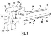
図1および図2を最初に参照すると、本開示に従う認証システムを含む外科手術ステープル留め器具が、全体的にステープラー10として示されている。ステープラー10は、ハンドルアセンブリ12と、ハンドルアセンブリ12から遠位方向に延びているアダプターアセンブリ14と、アダプターアセンブリ14の遠位端に選択的に固定されているローディングユニット16とを含む。ハンドルアセンブリ12、アダプターアセンブリ14、およびローディングユニット16の詳細な説明は、共有に係る米国特許出願公開第2012/0089131号に提供され、その内容は、その全体が本明細書中で参考として援用される。
Referring initially to FIGS. 1 and 2, a surgical stapling instrument that includes an authentication system in accordance with the present disclosure is generally illustrated as a
ハンドルアセンブリ12は、下方ハウジング部分17と、下方ハウジング部分17から延び、および/または下方ハウジング部分17において支持されている中間ハウジング部分18と、中間ハウジング部分18から延び、および/または中間ハウジング部分18において支持されている上方ハウジング部分19とを含む。中間ハウジング部分18および上方ハウジング部分19は、下方ハウジング部分17と一体的に形成され下方ハウジング部分17から延びている遠位半体セクション20aと、近位半体セクション20bとに分離され、この近位半体セクション20bは、取り付けの任意の適切な態様(例えば、限定されることなく、超音波溶接および/または複数のファスナー)によって、遠位半体セクション20aに接合されている。接合された場合、遠位半体セクション20aと近位半体セクション20bとは、ハンドルハウジング21を形成し、このハンドルハウジング21は、その中に空洞を規定し、この空洞は、コントローラー21aを含む回路基板、および駆動機構(示されない)を収容する。
The handle assembly 12 extends from the
下方ハウジング部分17は、ドア13を含み、このドア13は、中に電池(示されない)を保持するための、下方ハウジング部分17に形成されている空洞にアクセスするために、下方ハウジング部分17に旋回式に接続されている。ステープラー10は、例えば、限定されることなく、燃料電池、外部電力に接続されている電力コードなどのような任意の数の電源によって、電力供給され得ることが企図される。
The
アダプターアセンブリ14は、その近位端における駆動カプラー22と、その遠位端におけるローディングユニットカプラー15とを含む。上方ハウジング部分19の遠位半体セクション20aは、ノーズまたは接続部分11を規定し、このノーズまたは接続部分11は、アダプターアセンブリ14の駆動カプラー22を動作可能に受け取るように構成されている。ローディングユニット16は、アダプターカプラー27を含み、このアダプターカプラー27は、アダプターアセンブリ14のローディングユニットカプラー15を動作可能に受け取るように構成されている。
The
ハンドルハウジング21の上方ハウジング部分19は、駆動機構(示されない)を封入し、この駆動機構は、ステープラー10の様々な動作を実施するために、シャフトおよび/または歯車構成要素(示されない)を駆動するように構成されている。特に、駆動機構は、ローディングユニット16のツールアセンブリもしくはエンドエフェクター23をローディングユニット16の近位本体部分24に対して選択的に移動させること、ローディングユニット16を長手方向軸「X−X」(図1)周りにハンドルハウジング21に対して回転させること、アンビルアセンブリ25をローディングユニット16のカートリッジアセンブリ26に対して移動させること、および/またはローディングユニット16のカートリッジアセンブリ26内のステープル留めおよび切断カートリッジを発射させることを行うために、シャフトおよび/または歯車構成要素を駆動するように構成されている。
The
図1〜図21に示されるローディングユニット16は、線形外科手術ステープル留めローディングユニットである。ローディングユニットは、外科手術ステープルを形成するための凹部を有するステープル留めアンビルを含み、外科手術ステープルは、外科手術システムにおけるローディングユニットの動作によって、アンビルに対して駆動される。ステープルカートリッジは、外科手術ステープル、ならびにステープル発射アセンブリおよび/またはステープル駆動アセンブリを収容する。ステープル発射アセンブリおよび/またはステープル駆動アセンブリは公知である。1つのそのようなアセンブリは、米国特許第8,256,656号および同第7,044,353号に記載され、それらの開示全体は、これにより、本明細書中で参考として援用される。駆動アセンブリは、細長い駆動梁を含み、この細長い駆動梁は、ナイフ刃を有する。駆動梁は、作動そりを押し、この作動そりは、プッシャーとの相互作用のためのウェッジ形状の表面を有する。プッシャーは、ステープルを支持し、カム作用表面を有し、そりのウェッジ形状の表面がこのカム作用表面に対してスライドし、そりが長手方向の様式でステープルカートリッジを通して前進させられる間、プッシャーを上方向に駆動する。
The
ローディングユニットが、アンビルおよおびステープルカートリッジをそれぞれ支持するための顎部材を有することが企図される。アンビル顎部材およびステープルカートリッジ顎部材は、それらの間に組織を締め付けるように接近させられ得る。エンドエフェクターが、関節運動し得るか、または近位本体部分24によって規定される長手方向軸から軸を外れて旋回し得ることも企図される。
It is contemplated that the loading unit has jaw members for supporting the anvil and the staple cartridge, respectively. The anvil jaws and the staple cartridge jaws can be approximated to clamp tissue therebetween. It is also contemplated that the end effector may articulate or pivot off axis from the longitudinal axis defined by the
ローディングユニットが、円形外科手術ステープル留めユニット、他のタイプのステープル留めユニット、または他のタイプの外科手術エンドエフェクター(例えば、電気焼灼、切除、超音波など)であり得ることが企図される。 It is contemplated that the loading unit may be a circular surgical stapling unit, other types of stapling units, or other types of surgical end effectors (eg, electrocautery, ablation, ultrasound, etc.).
図3、図4、および図5を参照すると、アダプターアセンブリ14のローディングユニットカプラー15は、押しひねりまたは差し込みタイプの配置を介して、ローディングユニット16のアダプターカプラー27を動作可能に係合するように構成されている。アダプターカプラー27は、1つ以上の差し込みラグ28を含み、1つ以上の差し込みラグ28は、対応する1つ以上の差し込みチャネル29と嵌合するように構成されおり、対応する1つ以上の差し込みチャネル29は、アダプターアセンブリ14のローディングユニットカプラー15によって提供される差し込みカラー48において規定される。短いリンク部材44およびロードリンク部材45は、アダプターアセンブリ14内に長手方向に配置され、ステープラー10の動作中、長手方向に(例えば、遠位方向に、および近位方向に)並進するように構成されている。短いリンク部材44の遠位端に配置されているカム55は、ばね49aによって差し込みチャネル29に対して遠位方向に押し付けられる。ローディングユニット16をアダプターアセンブリ14と係合するために、ローディングユニット16のアダプターカプラー27は、アダプターアセンブリ14のローディングユニットカプラー15の中に挿入され、回転させられる。次に、差し込みカラー48は、アダプターカプラー27と協働して回転する。差し込みカラー48が回転する場合、カム55は、差し込みチャネル29から外れ、短いリンク部材44が遠位方向に並進することをもたらし、それは、次に、短いリンク部材44に形成されているスイッチタブ47がスイッチ46を作動させることをもたらす。スイッチ46は、コントローラー21aと動作可能に電気的に通信しており、ローデングユニット16とアダプターアセンブリ14との間の係合状態をコントローラー21aに伝えるように構成されている。
Referring to FIGS. 3, 4 and 5, the
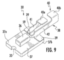
次に図6〜図10に目を向けると、ローディングユニット16のアダプターカプラー27は、認証基板アセンブリ30を含み、この認証基板アセンブリ30は、アダプターカプラー27において規定される凹部31内に固定して取り付けられるように構成されている。認証基板アセンブリ30は、ローディングユニット16がアダプターアセンブリ14に固定されている場合、認証基板アセンブリ30が、アダプターアセンブリ(図11)のローディングユニットカプラー15内に取り付けられているアダプター基板アセンブリ50を係合するように、アダプターカプラー27内に位置決めされる。より詳細には、認証基板30は、回路基板37と、1対の接触部材40a、40b(集合的に接触部材40)と、チップ36とを含む。回路基板37は、実質的に平面の細長い部材を規定し、この実質的に平面の細長い部材は、アダプターカプラー27によって規定される凹部31内に固定して受け取られるように構成されている。チップ36は、接触部材40と電気的に通信している。回路基板37の遠位端37aは、チップ36を支持し、回路基板37の近位端37bは、接触部材40を支持している。回路基板37の遠位端37aは、その中に規定される整列切欠き33を含み、この整列切欠き33は、アダプターカプラー27内での認証基板アセンブリ30の確実で正確な位置決めを確実にするために、凹部31の遠位端に提供される対応する整列ナブ32を係合するように構成されている。
Turning now to FIGS. 6-10, the
チップ36は、ローディングユニット16の仕様(例えば、限定されることなく、カートリッジサイズ、ステープル配置、ステープル長、締め付け距離、製造日、耐用年数、適合性特性、特有の識別名(例えば、シリアル番号)、および/または使用回数)を記憶すること、および仕様をハンドルアセンブリ12に伝送することが可能な任意のチップを含む。いくつかの実施形態において、チップ36は、消去可能なプログラム可能読み取り専用メモリー(「EPROM」)チップを含む。この態様において、ハンドルアセンブリ12は、チップ36から伝送されるローディングユニット16の仕様に従って、その発射力、発射行程、および/または他の動作上の特性を調整し得る。チップ36が、書き込み能力を含み得ることがさらに想定され、この書き込み能力は、ハンドルアセンブリ12が、関連付けられているローディングユニット16が使用されたことをチップ36に通信することを可能にし、それは、使用済みリロードアセンブリの再装填もしくは再使用、または任意の他の許可されていない使用を防止し得る。
The tip 36 has a specification of the loading unit 16 (e.g., without limitation, cartridge size, staple placement, staple length, clamping distance, manufacturing date, service life, compatibility characteristics, unique identification name (e.g. serial number) And / or storing any number of uses) and any chip capable of transmitting the specification to the handle assembly 12. In some embodiments, chip 36 includes an erasable programmable read only memory ("EPROM") chip. In this manner, the handle assembly 12 may adjust its firing force, firing stroke, and / or other operational characteristics in accordance with the specifications of the
いくつかの実施形態において、チップ36は、安全な認証チップ(例えば、限定されることなく、San Jose,CaliforniaのMaxim IntegratedTMによって製造される、1−Wire SHA−256および512−Bit User EEPROMを有するDS28E15 DeepCoverTM Secure Authenticator)を含む。これらの実施形態において、チップ36の内容、およびチップ36とハンドルアセンブリ12との間の通信は、許可されていないアクセスを防止するために暗号化される。この態様において、低品質の偽物のローディングユニット、再製品化されたローディングユニット、または「模造品」ローディングユニットの使用が有効に妨げられ、そのことは、次に、新しい真正のローディングユニット16のみが外科手術手順中に使用されることを確実にすることによって、患者に対するリスクを低減する。さらに、医療施設および/または外科医が、知らず知らず偽物のローディングユニットを使用し得る可能性は大いに抑えられ、従って、医療サービスを届けることに関して、社会に対する費用全体を低減する。いくつかの実施形態において、チップ36は、「1−wire」通信インターフェイスを利用し、それにより、チップ36とハンドルアセンブリ12との間の二方向性直列通信のために、単一の信号コンダクターが接地コンダクターと一緒に用いられる。
In some embodiments, the chip 36 is secure authentication chip (e.g., without limitation, San Jose, manufactured by California of Maxim Integrated TM, a 1-Wire SHA-256 and 512-Bit User EEPROM with including the DS28E15 DeepCover TM Secure Authenticator). In these embodiments, the contents of chip 36 and communications between chip 36 and handle assembly 12 are encrypted to prevent unauthorized access. In this aspect, the use of a low quality fake loading unit, a refurbished loading unit, or a "imitation" loading unit is effectively impeded, which in turn only new
接触アセンブリ38(図9、図10)は、短い接触アーム41と長い接触アーム42とを含み、短い接触アーム41と長い接触アーム42とは、接触基部59によって接合され、ほぼ細長いu字形の構成を有する。短い接触アーム41は、第1の接触部材40aを含み、この第1の接触部材40aは、短い接触アーム41の近位端の上方部分に対して、直交して配置され、それに固定されている。長い接触アーム42は、第2の接触部材40bを含み、この第2の接触部材40bは、長い接触アーム42の近位端の上方部分に対して、直交して配置され、それに固定されている。短い接触アーム41および長い接触アーム42は、各々、ソルダータブ39を含み、このソルダータブ39は、それらの遠位端の下方部分に対して、直交して配置され、固定されている。ソルダータブ39は、例えば、はんだ付け、電気伝導性接着剤、および/または他の適切な技術によって、回路基板37の近位端37bに電気機械式に接合されている。
The contact assembly 38 (FIGS. 9, 10) includes a
アダプターカプラー27は、その近位端から半径方向に延びている高くなった接続支持部34を含み、その中に規定される1対のクレードル35a、35bを含み、1対のクレードル35a、35bは、認証基板アセンブリ30がアダプターカプラー27の凹部31内に位置決めされている場合、それぞれ、第1の接触部材40aおよび第2の接触部材40bを受け取るように構成されている。カバー43は、認証基板アセンブリ30をアダプターカプラー27の凹部31内に封入し、保持するように構成されている(図7および図8)。
The
いくつかの実施形態において、短い接触アーム41および第1の接触部材40aは、接触基部59によって長い接触アーム42および第2の接触部材40bから電気的に絶縁されている。これらの実施形態において、短い接触アーム41および長い接触アーム42の各々は、別個の回路の役割を果たし、例えば、短い接触アーム41は、信号の役割を果たし、長い接触アーム42は、接地の役割を果たす。他の実施形態において、短い接触アーム41および第1の接触部材40aは、長い接触アーム42および第2の接触部材40bと電気的に接合されている。これらの実施形態において、短い接触アーム41および長い接触アーム42は、信号回路の役割を果たすために、分岐したモードまたは冗長モードで動作し、一方で、接地回路は、ローディングユニット16、アダプターユニット14、および/またはハンドルアセンブリ12の他の電気伝導性構成要素によってその役割を果たされる。
In some embodiments, the
上で言及されるように、認証基板アセンブリ30は、ローディングユニット16がアダプターアセンブリ14に固定されている場合、ローディングユニットカプラー15内に取り付けられているアダプター基板アセンブリ50を係合するように構成されている。次に図11〜図14を参照すると、ローディングユニットカプラー15は、アダプター基板アセンブリ50を含み、このアダプター基板アセンブリ50は、ローディングユニットカプラー15の中に規定されるポケット60内に浮動的に取り付けられるように構成されている。アダプター基板アセンブリ50は、ローディングユニット16がアダプターアセンブリ14に固定されている場合、アダプター基板アセンブリ50が認証基板アセンブリ30を係合するように、ローディングユニットカプラー15内に位置決めされる。
As mentioned above, the
アダプター基板アセンブリ50は、回路基板51を含み、この回路基板51は、回路基板51に固定された1対の接触部材55a、55b(集合的に接触部材55)を有し、1対の接触部材55a、55bは、ハンドルアセンブリ12と動作可能に通信する。例示される実施形態において、接触部材55a、55bは、本明細書中に記載されるように、ローディングユニット16とアダプターアセンブリ14との回転式のカップリングに適応させるために、例えば、ステープラー10の長手方向軸「X−X」に対して横断する横方向への有効な係合のために配置される。
The
回路基板51は、上表面51aと、下表面51bと、近位端51cと、遠位端51dとを含む。回路基板51は、実質的に平面の細長い部材を規定し、この実質的に平面の細長い部材は、ローディングユニットカプラー15によって規定されるポケット60内に弾力的または浮動的に受け取られるように構成されている。ばねクリップ52は、回路基板51の近位端51cに固定され、アダプター基板アセンブリ50をポケット60内で支持するように構成されている。ばねクリップ52は、翼のような構成を有する1対のばね支持部54を含み、1対のばね支持部54は、ばねクリップ52が過剰に伸長することを防止し、そこに剛性を提供するように構成されている。アダプター基板アセンブリ50は、広い湾曲したu字形のプロフィールを有するばね53を含み、このばね53は、回路基板51の上表面51a上に配置されている。いくつかの実施形態において、ばねクリップ52およびばね53は、一体的に形成され得る。ばねクリップ52および/またはばね53は、回路基板51の近位端51cに規定される切欠き62によって、確実に整列させられ得、および/または支持され得る。回路基板51は、その中に規定される1つ以上のスルーホール56を含み、1つ以上のスルーホール56は、回路基板51の上表面51aと下表面51bとの間に伝導性経路を形成するために利用され得る。
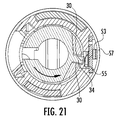
アダプター基板アセンブリ50がポケット60内に取り付けられている場合、ばね53は、アダプターアセンブリ14(図15、図16)の外側チューブ57に対抗して位置している。使用において、アダプター基板50は、ばね53によって、および側面ばねクリップ52によって、認証基板アセンブリ30に向かってばね付勢され、それによって、ローディングユニット16とアダプターアセンブリ14との接合時、ローディングユニット16とアダプターアセンブリ14との間の任意の製造公差は、ポケット60内でのアダプター基板50の浮動的ばね取り付け部の係合によって補われる。ばね53に加えて、付勢する代替の方法が再度企図される。この態様において、アダプター基板50の接触部材55と認証基板アセンブリ30の接触部材40との間の確実な接続は、一貫して達成され、従って、チップ36とハンドルアセンブリ12との間に強固な通信リンクを提供する。実施形態において、接触アセンブリ38、接触部40、および/または接触部55は、電気伝導性材料(例えば、限定されることなく、ベリリウム銅)から少なくとも部分的に形成されている。
When the
次に図15〜図21に目を向けると、アダプター基板アセンブリ50と認証基板アセンブリ30との間の相互作用が示されている。図15、図16、および図19に見られるように、アダプター基板50は、ばねクリップ52によって、ローディングユニットアダプター15内に保持されている。ばね53は、外側チューブ57に対抗して位置することにより、アダプター基板50をボア61に向かって内方に付勢し、その結果、接触部材55はボア61の中に延びている。アダプターカプラー27がローディングユニットアダプター15のボア61の中に完全に挿入されている場合、アダプターカプラー27とローディングユニットカプラー15との最初の回転の向きは、認証基板30の接触部材40とアダプター基板50の接触部材55とが、おおよそ45°離れているようなものである(図20)。ローディングユニット16がアダプターアセンブリ14に対して回転させられる場合、認証基板30の接触部材40は、アダプター基板50の接触部材55との係合に至らせられる。有利には、ローディングユニット16のアダプターカプラー27の接触支持部34は、接触部材30がアダプター基板50の嵌合接触部材55を係合している場合、接触部材30に半径方向の支持を提供する。さらに、ばね53は、外側チューブ57に対抗して位置し、それは、アダプター基板50が認証基板30およびローディングユニットカプラー15に対して浮動することを可能にし、それにより、様々な構成要素間の製造差異を補い、認証基板30とアダプター基板50との間の確実な接続を提供する。
Turning now to FIGS. 15-21, the interaction between
ローディングユニット16のようなローディングユニットは、取り外し可能かつ交換可能なステープルカートリッジアセンブリを有し得ることが企図される。本開示の実施形態に従うステープル留めシステムが、図22〜図57に示され、このステープル留めシステムは、上で議論されたハンドルアセンブリ12と同様の動力式ハンドルアセンブリ112を有する。ハンドルアセンブリは、上で議論されるように構成され、コントローラー121aを有する。ステープル留めシステムは、アダプターアセンブリ114とローディングユニット116とを含み、それらの各々は、上で議論されるように構成され得る。ローディングユニットは、線形ステープル留めローディングユニットであるが、他のタイプのローディングユニットが企図される。ローディングユニット116は、上で議論されるように、アンビル顎部材111とステープルカートリッジ顎部材113との間に締め付けられている組織へステープルを発射するための駆動アセンブリを有する。
It is contemplated that the loading unit, such as the
ステープルカートリッジ顎部材113の中に支持されているのは、取り外し可能かつ交換可能なステープルカートリッジアセンブリ115である。取り外し可能かつ交換可能なステープルカートリッジアセンブリは、US 2013−0098965 A1として公開された、2011年10月25に出願された米国特許出願第13/280,880号に開示され、その開示全体は、これにより、本明細書中で参考として援用される。
Supported within the staple
本開示のローディングユニット116は、1回より多く使用されるように構成されている。特に、ローディングユニットは、取り外し可能なステープルカートリッジアセンブリ115を有し、この取り外し可能なステープルカートリッジアセンブリ115は、上で議論されたステープルカートリッジと駆動アセンブリとを含む。取り外し可能なアセンブリ116は、(例えば、ステープルまたは他の外科手術ファスナーをそこから発射した後)取り外され、かつ交換されるように構成されている。示されるローディングユニット116は、近位本体部分118を含み、この近位本体部分118は、アダプターアセンブリ114に対して取り付け可能である。しかし、本開示のローディングユニットの特徴は、器具の細長い部分の分離可能な部分を含まない外科手術器具の中に組み込まれ得る。
The
ローディングユニット500は、長手方向軸「A−A」を規定する近位本体部分118を含む。顎部材は、アンビル顎部材111とカートリッジ顎部材113とを含む。顎部材のうちの一方は、顎部材の間の組織の締め付けを可能にするために、他方に対して旋回式である。例示される実施形態において、カートリッジ顎部材113は、アンビル顎部材に対して旋回式であり、開放位置または締め付けられていない位置と、閉鎖位置または締め付けられている位置との間を移動可能である。しかし、アンビル顎部材、またはカートリッジ顎部材およびアンビル顎部材の両方は、移動可能であり得る。図1〜図21に関して議論されるように、アンビル顎部材は、複数のステープル形成くぼみを有するアンビルを含む。
カートリッジ顎部材113は、チャネルまたはキャリアー120を含み、このチャネルまたはキャリアー120は、ステープルカートリッジアセンブリ115を受け取り、支持する。カートリッジアセンブリは、カートリッジ本体140と支持プレート111aとを有する。カートリッジ本体および支持プレートは、下で議論されるようなスナップばめ接続、移動止め、ラッチによって、または別のタイプの接続によって、チャネルまたはキャリアー120に取り付けられる。カートリッジアセンブリは、ファスナーまたはステープル141を含む。カートリッジ本体140は、複数の側方に間隔が空けられているステープル保持スロット142を規定し、複数の側方に間隔が空けられているステープル保持スロット142は、開口部(図32を参照のこと)として構成されている。各スロットは、その中にファスナーまたはステープルを受け取るように構成されている。カートリッジアセンブリは、複数のカムウェッジスロットも規定し、複数のカムウェッジスロットは、ステープルプッシャー146を収容し、上で議論されるように、ステープルの発射において、作動そり148が複数のカムウェッジスロットを長手方向に通過するために、底部が開放されている。
取り外し可能なステープルカートリッジアセンブリ115は、カートリッジ本体140と支持プレート111aとを含む。取り外し可能なアセンブリ115は、例えば、ステープルがカートリッジ本体140から発射された後、チャネル120から取り外し可能である。別の取り外し可能かつ交換可能なステープルカートリッジアセンブリは、さらなるファスナーまたはステープルを発射するために、ローディングユニット116が再び作動させられ得るように、チャネルの中に装填されることが可能である。
The removable
チャネル120は、ステープルカートリッジアセンブリおよび支持プレート(図39を参照のこと)を係合するための1つまたは1対の係合構造120a(例えば、スロット)と、駆動梁の通行のための中央スロットと、アンビル顎部材との接続のための1対の近位ホール150と、傾斜した表面152とを含む。近位ホール150は、アンビル顎部材における1対の対応するホールまたは特徴と整列/機械的に係合するように構成されている。顎部材は、例えば、アンビル顎部材111とカートリッジ顎部材113との間の旋回関係を容易にするために、ピンによって接続され得る。
カートリッジ本体140は、中央スロット143と、ステープル保持スロットの列とを含み、ステープル保持スロットの列は、スロット143(図32を参照のこと)の各側に位置決めされている。カートリッジ本体は、1対の係合構造または突出部も含み、1対の係合構造または突出部は、特定の実施形態において、支持プレート111aおよび/またはチャネル120との接続のための、カートリッジ本体の近位端に隣接するスロットまたは開口部であり得る。
The
図29を特に参照すると、支持プレート111aは、基部145と、カートリッジ本体および/またはチャネルとの接続のための係合特徴147および147a(図38を参照のこと)と、その近位端における取り付け部分149とを含む(図29を参照のこと)。支持プレート111aは、カートリッジ本体の下に配置されることにより、ステープルプッシャー、作動そり、およびステープル(または他の外科手術ファスナー)を支持し、それらの構成要素がステープルカートリッジアセンブリの外に落ちることを防止する。
With particular reference to FIG. 29, the support plate 111a is mounted at its proximal end with the
ローディングユニットは、チップアセンブリ360を含み得、このチップアセンブリ360は、例えば、図41〜図45に示されるように、近位本体部分118の近位端に取り付けられる。チップアセンブリは、上で議論された認証基板アセンブリ30に関して、上に記載される通りである。チップアセンブリ360は、アダプターアセンブリ114の遠位端におけるカプラーにおける基板アセンブリとの接続のために取り付けられ、図1〜図21に関して上で議論されるように構成され得る。チップアセンブリ360は、認証および情報の目的のためにチップ361を含み、特定の情報を記憶するメモリーを含み得る。情報は、ローディングユニットが属するデバイスのタイプ、デバイス/ローディングユニットのバージョン、ローディングユニットの名称、製造ロット番号、シリアル番号または他の識別番号、ローディングユニットの駆動梁が駆動され得る最大の力、インターロックゾーン(mm)、エンドゾーン(mm)、ローディングユニットが関節運動し得るかどうか、および/または使用限度(ローディングユニットが使用され得る回数)を含み得る。インターロックゾーンは、駆動梁がローディングユニットにおけるロックアウトによって係合されている場合に、駆動梁の開始位置または最初の位置から測定される駆動梁の位置(ミリメーターで)である。ロックアウトの例は、下で議論される。エンドゾーンは、ステープルカートリッジ本体140において、駆動梁が、その移動の終了に達した場合に、駆動梁の開始位置または最初の位置から測定される駆動梁の位置(ミリメーターで)である。ステープルカートリッジアセンブリ115は取り外され、かつ交換され得るので、ローディングユニットが新しい発射されていないステープルカートリッジで再装填され得る回数に対し、意図された限度が存在する。チップに記憶されている情報は、ステープルラインの長さおよび/またはステープルカートリッジの長さを含み得る。
The loading unit may include a
ハンドルアセンブリ112におけるコントローラー121aは、チップ361における情報を読み取るようにプログラムされ得るか、またはチップ361に記憶されている情報の関数として、他のコントローラーから命令を受け取るようにプログラムされ得る。この情報は、外科手術システムの動作において使用される。望ましくは、情報のうちのいくつかまたは全てが暗号化され、そのことは、図1〜図21に関して上で議論されるように達成され得る。コントローラーは、シリアル番号または他のデータが認識されない場合に、ハンドルアセンブリ112の中に配置されているモーター(示されない)に電力を提供しないように、ならびにアダプターアセンブリおよびローディングユニットを動作させないようにプログラムされ得る。様々なレベルの機能が、任意のシステムチップ(チップ361が挙げられるが、これに限定されない)の認証状況に基づいて、使用可能にされ得るか、または無効にされ得る。例えば、うまく認証しないシステムは、ステープル留めリロードが、締め付けること、関節運動すること、および低減された速度で回転することを可能にするが、発射することを可能にしないように設定され得る。最大力の情報は、外科手術システム中に配置されているロードセンサー(例えば、ひずみ計)とともに使用される。例えば、ロードセンサーが、アダプターアセンブリ114および/またはローディングユニットの中に配置され得る(例えば、駆動梁におけるロードセンサー)。コントローラーは、例えば、最大力が超過される前にモーター(示されない)の動作が中断または変更されるように、ロードセンサーからのデータをチップに記憶されている最大力のデータと比較するようにプログラムされている。別の例において、コントローラーは、測定された力が所定のレベルに達した場合、または任意の他の引き金となる測定規準が満たされた場合、「スローモード」で動作するようにプログラムされ得る。所定のレベルの力は、上で議論された最大力であり得るか、またはシステムにおけるチップ(例えば、チップ361)に記憶されている別のレベルの力であり得る。スローモードは、コントローラーがより遅い速度でモーター(示されない)を動作させ、また、組織の圧縮および/またはステープルの発射を遅らせることを意味する。厚い組織において、スローモードは、組織における流体がステープル留めの部位から離れるほうに移動することを可能にし得、組織のより強い圧縮を容易にする。負荷検出の代替の方法(例えば、組織の厚さの変化、厚さまたは圧縮の変化率を感知すること、ハンドルアセンブリのモーターにおける電流の引き込み、駆動アセンブリの移動の速度を監視することなど)が使用され得る。
The controller 121a in the
コントローラーは、ハンドルアセンブリにおけるモーターがどのように動作させられるべきかを決定するために使用されるフィードバックループを有し得ることが企図される。コントローラーは、経時的に力のプロフィールを比較するようにプログラムされ得るか、または経時的に負荷のプロフィールを比較するようにプログラムされ得る。モーター(示されない)の動作は、力または負荷のパターンが特定のローディングユニットについて予期されるようなものではない場合、またはある所定の最大の限度もしくは他の限度に達する前に、中断または変更される。コントローラーはまた、プロフィールに基づいて、上で議論されるように、「スローモード」で動作するようにプログラムされ得る。 It is contemplated that the controller may have a feedback loop used to determine how the motor in the handle assembly should be operated. The controller can be programmed to compare force profiles over time, or it can be programmed to compare load profiles over time. The operation of the motor (not shown) is interrupted or changed if the force or load pattern is not as expected for a particular loading unit, or before reaching some predetermined maximum or other limit. Ru. The controller may also be programmed to operate in "slow mode" as discussed above based on the profile.
同様の態様において、モーターの動作は、駆動梁がインターロックゾーン、エンドゾーン、または特定の目的の他の領域に配置されている場合、停止され得るか、またはスローモードで動作させられ得る。さらに、コントローラーは、ローディングユニットが関節運動していないことをチップ361におけるデータが示した場合、関節運動リンケージ、バー、またはケーブルの動作を中断または防止し得る。同様に、コントローラーは、ローディングユニットが特定のタイプのものであることをチップ361におけるデータが示した場合、システム回転の特性を中断または変更し得る。
In a similar manner, the motion of the motor may be stopped or operated in slow mode if the drive beam is located in the interlock zone, end zone or other area of particular purpose. Additionally, the controller may interrupt or prevent movement of the articulation linkage, bar or cable if the data at the
上で議論されたデータのうちのいくつかまたは全てを有するチップ361は、取り外し可能かつ交換可能なステープルカートリッジアセンブリを有しないローディングユニット、および/または関節運動しないローディングユニットを含む、本明細書中に開示される実施形態のうちの任意のものにおいて提供され得ることが企図される。
The
チップ361における情報が、ハンドルアセンブリにおけるコントローラー、システムにおける別のチップ、または外科手術システムにおける任意の他のコンピューター構成要素によって読み取られ得ることが企図される。
It is contemplated that the information in the
本明細書中に開示される実施形態のうちの任意のものにおいて、コントローラーは、ローディングユニットにおけるチップに情報を書き込み得る。例えば、上で議論されたロードセンサーによって測定された場合の、組織に対して締め付けるために使用された最大の力、ステープルを発射するために使用された最大の力、および/または駆動梁が前進することを止める場合の駆動梁の位置など。チップ361に書き込まれ得る他の情報は、デバイスがスローモードに入った場合の駆動梁の場所、ローディングユニットが発射された回数、ローディングユニットが発射されたかどうか、ハンドルアセンブリのタイプ、ハンドルアセンブリのシリアル番号、アダプターアセンブリのタイプ、鍵となる事象の日時、外科手術システムの構成要素の向き、温度および/またはアダプターアセンブリのシリアル番号を含む。ステープルを発射するための最大の力は、本明細書中に開示される実施形態のうちの任意のものにおいて、駆動梁の位置とともに保存され得る。情報はまた、ハンドルアセンブリにおけるコントローラーに接続されているメモリー、システムにおける他のチップ(複数可)、または外科手術システムの他のコンピューター構成要素に保存され得る。
In any of the embodiments disclosed herein, the controller may write information to the chip in the loading unit. For example, the maximum force used to clamp the tissue, the maximum force used to fire the staples, and / or the drive beam advanced as measured by the load sensor discussed above Such as the position of the drive beam when you stop doing things. Other information that may be written to
本明細書中に開示される実施形態のうちの任意のものにおいて、エンドエフェクターまたはツールアセンブリは、ツールアセンブリが長手方向軸「Y−Y」と整列させられている第1の位置と、ツールアセンブリが長手方向軸「Y−Y」に対して、ある角度で配置されている第2の位置との間を関節運動するために配置されていることも想定される。例えば、アンビル顎部材とカートリッジ顎部材とを含むツールアセンブリは、近位本体部分118に対して回転可能であるように取り付けられ得る。アンビル顎部材およびカートリッジ顎部材は、取り付けアセンブリ2020(下でさらに議論される)に取り付けられ得、取り付けアセンブリは、近位本体部分118に旋回可能に接続され得る。ローディングユニット116は、1つ以上のケーブルまたはリンケージを含み、1つ以上のケーブルまたはリンケージは、近位本体部分に配置されており、その結果、ケーブルまたはリンケージが動かされる場合、ツールアセンブリは、器具に対して旋回し、関節運動する。関節運動を提供することのさらなる詳細は、Millimanらに対する、共有に係る米国特許第6,953,139号に詳細に記載され、その内容は、これにより、それらの全体が参考として援用される。アダプターアセンブリ114は、ツールアセンブリの関節運動を可能にするリンケージ、バー、またはケーブルを含み得る。
In any of the embodiments disclosed herein, the end effector or tool assembly includes a first position where the tool assembly is aligned with the longitudinal axis "Y-Y"; It is also envisioned that is disposed to articulate between a second position which is disposed at an angle with respect to the longitudinal axis "Y-Y". For example, a tool assembly including an anvil jaw member and a cartridge jaw member may be rotatably mounted relative to the
図32に見られるように、例えば、本明細書中に開示される実施形態のうちの任意のものは、カートリッジ本体140を含み得、このカートリッジ本体140は、段を付けられた組織接触表面1412を有する。そのような実施形態において、異なるサイズのステープル、または全く同じサイズのステープルが使用され得る。複数のステープルサイズを有するステープルカートリッジのさらなる詳細は、Holstenらに対する米国特許第7,407,075号に含まれ、その内容全体は、これにより、本明細書中で参考として援用される。アンビルのステープル形成凹部、またはステープルプッシャー、またはそれらの両方は、所望の形状およびサイズでステープルを形成するように、それに応じて構成され得る。
As seen in FIG. 32, for example, any of the embodiments disclosed herein may include a
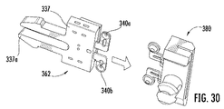
取り外し可能かつ交換可能なステープルカートリッジアセンブリ115は、チップアセンブリ362をさらに含み得る。(図27および図28を参照のこと)。対応する基板アセンブリ380(図25および図26)は、ローディングユニット116のツールアセンブリに配置されており、チャネル120に配置され得る。ツールアセンブリ基板アセンブリ380は、アダプターカプラー27のアダプター基板アセンブリ50に関して上で議論されるように構成され得る。ツールアセンブリ基板アセンブリ380は、チャネル120の壁に固定して取り付けられるように構成されている。この基板アセンブリ380は、カートリッジアセンブリ140がローディングユニットのチャネル120に固定されている場合、チップアセンブリ362が、チャネルに取り付けられている基板アセンブリ380を係合するように位置決めされる。(図29〜図31を参照のこと)。図27および図28は、チップアセンブリとステープルカートリッジ本体140との間の関係を示している一方で、図29は、チップアセンブリ362と支持プレート111aとの間の関係を示している。
The removable and replaceable
より詳細には、チップアセンブリは、本体337と、1対の接触部材340a、340b(集合的に接触部材340)とを含み、1対の接触部材340a、340bは、本体の中に配置されているチップ336に接続されている。本体337は、可撓なアームを有する長方形の部材を規定し、可撓なアームは、そこにスナップ特徴337aを有する。可撓なアームは、カートリッジ本体において規定される凹部331内に固定して受け取られるように構成されている。チップ336は、接触部材340と電気的に通信している。
More specifically, the tip assembly includes a
チップ336は、ステープルカートリッジアセンブリ115に関する情報を記憶することが可能な任意のチップを含む。チップは、認証基板アセンブリ30のチップと同じか、または同様であり得る。本明細書中に開示される実施形態のうちの任意のものにおいて、チップのうちの任意のものは、情報(例えば、限定されることなく、カートリッジサイズ、ステープル配置、ステープルラインの長さ(またはカートリッジの長さ)、製造日、耐用年数、適合性特性、特有の識別名(例えば、シリアル番号)、および/または使用回数、ならびにステープルカートリッジアセンブリが使用されたかどうか)を記憶し得る。そのような情報は、適切なバス、ピン接続、無線手段などを通して、ハンドルアセンブリ112におけるコントローラー、または別のコンピューター構成要素に伝送され得る。いくつかの実施形態において、チップ336は、消去可能なプログラム可能読み取り専用メモリー(「EPROM」)チップを含む。ハンドルアセンブリにおけるコントローラーは、情報をチップ336に書き込み得る。この態様において、ハンドルアセンブリ112は、チップ336から伝送されるステープルカートリッジアセンブリに関する情報に従って、その発射力、発射行程、および/または他の動作上の特性を調整し得る。ハンドルアセンブリ112は、ステープルカートリッジアセンブリが使用されたことをチップ336に通信し得、そのことは、使用済みリロードアセンブリの再装填もしくは再使用、または任意の他の許可されていない使用を防止し得る。外科手術システムにおける構成要素のうちの任意のものにおいて記憶されている情報は、個人鍵暗号化、公開鍵暗号化、および/または安全なハッシュアルゴリズムを用いて、暗号化され得るか、または不明瞭にされ得る。
The tip 336 includes any tip capable of storing information regarding the
本明細書中に開示される実施形態のうちの任意のものにおいて、外科手術システムにおける構成要素のチップに記憶されている情報は、構成要素のタイプ、再注文コード、シリアル番号、識別コード、ロット番号、システムとの適合性、耐用年数、製造日、プログラミング日、設計バージョン、材料表、外科医による選択、性能特性、および/または構成要素についての銘柄(branding)を含み得る。例えば、そのような情報は、チップ361またはチップ336に記憶され得る。外科医による選択に基づいて特殊化またはカスタマイズされたローディングユニットが製造され得ること、および/またはローディングユニット、ステープルカートリッジアセンブリなどにおける1つもしくは複数のチップに記憶されている情報に基づいて「スローモード」もしくは「ファストモード」で動作させられるローディングユニットが製造され得ることが企図される。
In any of the embodiments disclosed herein, the information stored on the chip of the component in the surgical system includes: type of component, reorder code, serial number, identification code, lot It may include number, compatibility with the system, service life, date of manufacture, date of programming, design version, bill of material, choice by surgeon, performance characteristics, and / or branding of components. For example, such information may be stored on
本明細書中に開示される実施形態のうちの任意のものにおいて、取り外し可能かつ交換可能なステープルカートリッジアセンブリ、ローディングユニット、および/またはコントローラーは、ツールアセンブリの関節運動に関する情報を記憶しているチップまたはメモリーを含み得る。外科手術システムは、特定のセンサーおよび/またはエンコーダー(例えば、ホール効果センサー、ラジアルエンコーダー、線形エンコーダー、電位差計、加速度計、力変換器など)を含み、特定のセンサーおよび/またはエンコーダーは、ローディングユニットにおける駆動アセンブリの位置および/またはアダプターアセンブリにおける対応する構成要素の位置を決定し得る。例えば、ツールアセンブリは、ツールアセンブリの関節運動を作動する関節運動リンケージを含む。コントローラーは、センサーまたはエンコーダーを介してリンケージの位置を監視し得、ツールアセンブリが関節運動させられた程度を決定し得る。さらに、ツールアセンブリが関節運動させられた回数は、ステープルカートリッジアセンブリ、アダプター、コントローラー、または他のコンピューター構成要素のチップまたはメモリーに記憶され得る。ツールアセンブリが完全に関節運動させられた位置に達した場合のリンケージの位置に関する情報が記憶され得る。 In any of the embodiments disclosed herein, a removable and replaceable staple cartridge assembly, a loading unit, and / or a tip that stores information regarding articulation of the tool assembly Or may include memory. The surgical system includes specific sensors and / or encoders (e.g. Hall effect sensors, radial encoders, linear encoders, potentiometers, accelerometers, force transducers etc), and the specific sensors and / or encoders are loaded unit The position of the drive assembly at and / or the position of corresponding components in the adapter assembly may be determined. For example, the tool assembly includes an articulation linkage that actuates articulation of the tool assembly. The controller may monitor the position of the linkage via a sensor or encoder and may determine the degree to which the tool assembly has been articulated. Additionally, the number of times the tool assembly has been articulated may be stored in the tip or memory of the staple cartridge assembly, an adapter, a controller, or other computer component. Information regarding the position of the linkage when the tool assembly has reached a fully articulated position may be stored.
基板アセンブリ380(図25および図26を参照のこと)はまた、1対の接触部380aおよび380bと、本体381とを有する。基板アセンブリは、ステープルカートリッジアセンブリがチャネル120の中に適切に取り付けられている場合、チップアセンブリ362との接触のために取り付けられる。接触部380a、380b、340a、および340bは、それらが互いに弾力的に係合し得るように、図面に見られるようなL字形の構成を有する。本体381は、スナップ特徴382を規定し得、このスナップ特徴382は、基板アセンブリを固定して取り付けるために、チャネルにおけるホール383を係合するように提供されている。基板アセンブリは、チップアセンブリ362からハンドルアセンブリにおけるコントローラーへ、コントローラーからチップアセンブリへ、または任意の他のコンピューターデバイスへ、および任意の他のコンピューターデバイスからの、情報の伝送のために、バス、ワイヤーに適切に接続されているか、または無線通信器を有する。
Substrate assembly 380 (see FIGS. 25 and 26) also includes a pair of
本明細書中に開示される実施形態のうちの任意のものにおいて、ロックアウト機構500が、ローディングユニットに配置されている。ローディングユニットは、上で議論されるように構成され得る。さらに、本開示は、ロックアウト、またはロックアウトを有するローディングユニットを有する取り外し可能なアセンブリに関する。
In any of the embodiments disclosed herein, a
ロックアウト機構500は、ラッチ2010と少なくとも1つのばね2030とを含み、ロックアウト機構500は、ステープルカートリッジが発射された後、かつ別のカートリッジアセンブリ115の装填前、ステープルカートリッジアセンブリ115またはステープルカートリッジ26の再発射を防止し、駆動梁の遠位方向の並進も防止するように構成されている。ロックアウト機構500は、図50において、そり148および取り付けアセンブリ2020と一緒に示されている。少なくとも1つのばね2030は、遠位方向に向いている表面2031に取り付けられる。例えば、凹部が、ばね2030を受け取るために、表面2031に形成されている。対応するポストが、ラッチ2010の近位方向に向いている表面に提供される。ラッチは、ローディングユニット内で旋回可能であるように構成され、少なくとも1つのプロング2012と、後部部分2014と、支持部分2016とを含む。ラッチは、2つの下方に延びている特徴として図50および図51に示されている支持部分2016の周りを旋回するように構成され、1つまたは複数のばね2030によって付勢されている。そり148は、ラッチおよび駆動梁がそれらの最初の位置にある場合に少なくとも1つのプロング2012を受け取るためのホールまたは凹部を有する。(図52を参照のこと)。駆動梁2039は、動的締め付け部材2040と相互作用し得るか、または動的締め付け部材2040を含み得、この動的締め付け部材2040は、上方フランジ2042と、下方フランジ2044と、ナイフ刃2046とを有する。(図53を参照のこと)。
最初の位置において、ラッチ2010は、前方方向または遠位方向に付勢されており、後部部分2014は、ラッチのさらなる回転式の移動を防止する駆動梁2039におけるエッジ2039aと接触している。駆動梁および動的締め付け部材が前方方向または遠位方向に移動させられる場合、動的締め付け部材は、そりを遠位方向に押す。そりの後部部分148aは、1つまたは複数のプロング2012を押し、ラッチを少なくとも1つのばね2030の付勢に抗して傾斜させる。これは、後部部分2014をエッジ2039a付近の領域から取り除き、駆動梁および動的締め付け部材が前方に移動することを可能にする。動的締め付け部材がラッチ2010を通過した後、ラッチは、ばねの影響下で前方に回転する。(図57を参照のこと)。
In the initial position, the
動的締め付け部材およびそりがカートリッジ140からステープルを発射した後、動的締め付け部材は、近位方向に移動させられ、そりをカートリッジ140およびカートリッジアセンブリ115の遠位端に残す。動的締め付け部材は、カム表面2041がラッチを移動経路外に移動させるので、ラッチ2010を越えて移動することができる。(図57を参照のこと)。動的締め付け部材が最初の位置に戻ると、ラッチ2010は、動的締め付け部材2040の別の前方移動を防止する。ラッチ後部部分2014は、駆動梁の別のエッジ2039bを係合するための位置にある。(図57を参照のこと)。ローディングユニットが、取り外し可能かつ交換可能なステープルカートリッジアセンブリ115を受け入れるタイプのものである場合、カートリッジアセンブリ115は、駆動梁および動的締め付け部材が再び遠位方向に移動させられることにより、別の組のステープルを発射し得るように、ラッチ2010を最初の位置に戻すように構成され得る。
After the dynamic clamping member and sled eject the staples from the
上で議論されるように、本明細書中に開示される実施形態のうちの任意のものは、ローディングユニット116のような外科手術ステープル留めローディングユニットにおいて、チップアセンブリ360を含み得、このチップアセンブリ360は、ロックアウト機構(例えば、上で議論されたロックアウト機構)に関する情報をチップアセンブリ360上に有する。さらに、ロックアウト機構に関する情報は、チップ361に記憶され得る。例えば、ロックアウト機構が係合されたという事実は、ハンドルにおけるコントローラーによって、チップアセンブリ360および/またはチップアセンブリ362に記録され得る。ハンドルにおけるコントローラーは、情報を記憶するためのメモリー(プロセッサーを含む)と他のコンピューター構成要素とを含み得る。コントローラーは、ハンドルアセンブリのモーターにおける電流を測定するために、電流計器、または電流計も含み得る。コントローラーは、ローディングユニットおよび/またはステープルカートリッジアセンブリの使用中に達したピーク電流を記録するようにプログラムされ得、そのピーク電流をシステムにおけるチップまたは他のコンピューター構成要素のうちの任意のものに記録し得る。ステープルが発射された後に達したピーク電流は、新しいステープルカートリッジアセンブリがローディングユニットの中に取り付けられる前にローディングユニットが2回目の発射を試みられたことを示すものであり得る。あるいは、ロックアウト機構は、例えば、ラッチなどにおいて、センサーを含み得る。外科手術システムが、上で議論されたもののようなロックアウト機構を有しないローディングユニットを含み得ることが企図される。ローディングユニットがロックアウト機構を有しないという事実は、チップ361に記憶され得る。
As discussed above, any of the embodiments disclosed herein may include a
含まれ得るエンコーダーのタイプのうちの1つは、ハンドルアセンブリにおけるものである。モーター出力シャフトまたはシステムの任意の他の部品の回転が何回なされたかを決定するエンコーダーが提供され得、このエンコーダーは、アダプターアセンブリにおける駆動バー、リンケージ、ケーブルなど、ローディングユニットにおける発射バー、または他の構成要素の位置を決定するために使用され得る。あるいは、他のセンサーが、外科手術システムにおける様々な構成要素の位置を決定するために使用され得る。 One of the types of encoders that may be included is in the handle assembly. An encoder may be provided that determines how many times the motor output shaft or any other part of the system has been rotated, such as a drive bar on an adapter assembly, a linkage, a cable, a firing bar on a loading unit, or other Can be used to determine the position of the components of Alternatively, other sensors may be used to determine the position of various components in the surgical system.
本明細書中に開示されるアダプターアセンブリは、本明細書中に開示される実施形態のうちの任意のものにおいて、米国公開出願第2011/0174099 A1号に開示されるように構成され得、その開示全体は、これにより、本明細書中で参考として援用される。ハンドルアセンブリにおけるモーターは、回転シャフトに回転出力を提供し、アダプターは、線形移動リンケージまたはバーへ、その出力を変換するように構成され、ハンドルアセンブリにおけるモーターはまた、ローディングユニット116の近位本体部分118における関節運動リンケージへ駆動を提供し得る。ハンドルアセンブリおよび/またはアダプターアセンブリは、米国公開出願第2014/0012289 A1号および同第2014/0110453 A1号に開示されるように構成され得、それらの開示全体は、これにより、本明細書中で参考として援用される。
The adapter assembly disclosed herein may, in any of the embodiments disclosed herein, be configured as disclosed in US Published Application No. 2011/0174099 A1, which The entire disclosure is hereby incorporated herein by reference. The motor in the handle assembly provides rotational output to the rotational shaft, and the adapter is configured to convert its output into a linear movement linkage or bar, and the motor in the handle assembly also includes the proximal body portion of the loading unit 116 A drive may be provided to the articulation linkage at 118. The handle assembly and / or adapter assembly may be configured as disclosed in US Published
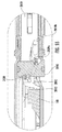
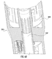
外科手術システムにおいて、ローディングユニットは、異なるタイプの外科手術ステープル留めローディングユニットであり得、ハンドルにおけるモーターの出力を特定のローディングユニットに適合させるための対応するアダプターを有する。例えば、ローディングユニットの1つのタイプは、円形ステープル留めローディングユニット2201である。図58を参照のこと。上で議論されるローディングユニット116とは対照的に、ローディングユニット2201のアンビル2203は、その組織接触表面を平行関係に維持しながら、ステープルカートリッジアセンブリ2205に向かって移動し、およびステープルカートリッジアセンブリ2205から離れるほうに移動する。ロッドは、アンビル2203の移動を達成するために、前進および後退させられる。ステープルの発射と組織の切断とを達成するために、別個のアクチュエーターが存在する。対照的に、上で議論される動的締め付け部材は、組織に対するツールアセンブリの締め付けを達成し、ステープルの発射も達成する。ローディングユニット2201が上で議論されるハンドルアセンブリ112のようなハンドルアセンブリとともに使用され得るように、適切なアダプター(示されない)が提供される。アダプターは、湾曲させられ得るシャフト2206と、外科医が組織の管状セクションをアンビルおよびカートリッジ構成要素/アセンブリの周りに配置できるように、アンビル2203をステープルカートリッジ構成要素2205から一定の間隔に置くためのケーブル、リンケージ、および/もしくはバー、またはそれらの組み合わせとを有する。周知であるように、アンビルは、カートリッジアセンブリと接近させられ得、ステープルは組織を通して発射され得る。その後、円形ナイフは、組織をステープルの線の内側で切断する。
In a surgical system, the loading unit can be a different type of surgical stapling loading unit and has a corresponding adapter to adapt the output of the motor at the handle to the particular loading unit. For example, one type of loading unit is a circular
例えば、ローディングユニット2201は、ロッドのための通路2207を有し得、このロッドは、アダプターにおけるアクチュエーターに接続しており、アダプターにおけるアクチュエーター(例えば、リンケージ、ケーブル、ロッドなど)は、ハンドルアセンブリの動力式(例えば、動力化)出力によって駆動される。図60を参照のこと。上で議論されるように、アンビル2203を移動させるのはロッドである。ローディングユニットは、図60に示されるように、ステープルカートリッジアセンブリの受け取りのための空間2209も有し、または代替的に、ローディングユニットは、永久的に取り付けられているステープルカートリッジを有し得る。ローディングユニット2201は、ステープルを発射するためのステープルプッシャーと、組織を切断するためのナイフとをさらに有する。
For example, the
従って、ハンドルアセンブリにおける様々なアクチュエーターの機能性を変えるために、外科手術システムのコントローラーを使用することが望ましい場合がある。例えば、ハンドルアセンブリ112は、プッシュボタン、揺動スイッチ、タッチスクリーン特徴、および/または別のタイプのアクチュエーター(本明細書中で一般に「ボタン」と呼ばれる)を有し得る。ローディングユニット116のような関節運動ローディングユニットの関節運動を開始すること、組織の締め付けを開始すること、ステープルの発射を開始すること、および組織の切断を開始することを行うために、少なくとも4つのそのようなボタンが提供される。特定の実施形態において、関節運動のための第1のボタン、ならびに締め付けおよび発射のための第2のボタンが存在する。ローディングユニット16またはローディングユニット116のような線形外科手術ステープル留めリロードが存在する場合、第2のボタンの機能を、締め付け、発射、および切断に変えるために、好ましくは、動力式(例えば、動力化)ハンドルアセンブリにおいてコントローラーが提供される。コントローラーは、第2のアクチュエーターの機能を締め付けに変えるようにもプログラムされ得、発射を開始するために第3のアクチュエーターの使用を可能にし、ローディングユニットがユニット2201のような円形ステープル留めローディングユニットである場合、切断を開始するために第4のアクチュエーターの使用を可能にする。特定の実施形態において、コントローラーは、上で議論されるローディングユニット16ような線形ステープル留めローディングユニットのツールアセンブリの関節運動を開始するためのボタンの使用を可能にするか、または防止するようにプログラムされる。本明細書中に開示される実施形態のうちの任意のものにおいて、ハンドルアセンブリ(または外科手術システムの別の構成要素)のコントローラーは、1つ以上のボタンの機能を変え、ある機能のためのボタンの使用を可能にし、および/またはある機能のためのボタンの使用を防止するようにプログラムされ得る。
Thus, it may be desirable to use a controller of a surgical system to alter the functionality of the various actuators in the handle assembly. For example, handle
円形ステープル留めローディングユニット2201は、図59に見られるように、チップ2221を有するチップアセンブリ2220を含み得、このチップアセンブリ2220は、図1〜図57に関して上に記載されるようなものであり得る。さらに、特定の実施形態において、ユニット2201は、取り外し可能かつ交換可能なカートリッジアセンブリ(示されない)を有し、この取り外し可能かつ交換可能なカートリッジアセンブリは、それ自体のチップアセンブリとチップとを有する。
The circular
コントローラープログラミングおよび/またはメモリーが、潜在的なローディングユニットのための潜在的なエンドストップまたは他の重要な場所に関する情報を含むことが望ましい。例えば、線形ステープル留めローディングユニットは、30mm、45mm、および/または60mmのステープルの線のユニットであり得、コントローラーは、駆動アセンブリがそれらの場所にある場合、様々なセンサーおよび/またはエンコーダーにおいて検出される力に関する情報を記憶するようにプログラムされ得る。本明細書中に開示される実施形態のうちの任意のものにおいて、目的のシステム中の移動可能な部品について任意の場所が使用され得ることが企図される。特定のローディングユニットにおいて適切なセンサー(例えば、パルスオキシメーター、温度メーターなど)が提供される場合、組織および/または周辺部位の状態に関する情報が、コントローラー、様々な構成要素におけるチップ、および/または他のコンピューター構成要素によって記憶され得る。企図される様々なタイプの外科手術ローディングユニット(例えば、ステープル留め、電気外科など)が存在し、それらは、様々な構成(例えば、異なるステープルの線の長さまたは直径、ステープルサイズ、エネルギーのレベルなど)で提供され得るので、各々と関連付けられている電流プロフィールが存在することが企図される。例えば、ローディングユニットの使用中、経時的にハンドルアセンブリにおける電流計器または電流計によって読み取られる電流は、読み取られ、保存され得る。コントローラーは、例えば、ローディングユニットの識別コードおよびタイプとともに、この電流プロフィールを保存することが企図される。この情報は、外科手術システムにおけるコントローラーまたは別の構成要素によって、公知の電流プロフィールと比較され得る。ステープルの発射、組織の状態、システムにおける使用されたローディングユニットまたは他の構成要素の状態、厚い組織などに関する推論がなされ得る。本明細書中に開示される実施形態のうちの任意のものにおいて、電流プロフィールは、上で議論されるようなシステムにおいて使用され得、および/または上で議論されるようなシステムにおいて保存され得る。例えば、下に示されるグラフは、そのようなプロフィールを表す。電流は、「A」において制限され始め、機械的負荷が増大する場合、RPMは減少する。RPMが、設定された制限「Y」よりも下に減少すると、デバイスは、第2のモードに切り替わる。このモードは、電流制限を「B」に増大させ、所望のRPMを「X」から「Z」に変える。このRPM変化は、ユーザーに視覚および可聴フィードバックを提供する。 It is desirable for the controller programming and / or memory to include information regarding potential end stops or other important locations for potential loading units. For example, a linear stapling loading unit may be a unit of 30 mm, 45 mm and / or 60 mm staple lines, and a controller may be detected at various sensors and / or encoders when the drive assembly is in their place It can be programmed to store information on the force. In any of the embodiments disclosed herein, it is contemplated that any location may be used for movable parts in the system of interest. If a suitable sensor (eg, pulse oximeter, temperature meter, etc.) is provided in a particular loading unit, information regarding the condition of the tissue and / or surrounding area may be provided by the controller, tip in various components, and / or other May be stored by computer components of the There are various types of surgical loading units contemplated (e.g., stapling, electrosurgery, etc.), which have various configurations (e.g., different staple line lengths or diameters, staple sizes, energy levels) Etc., it is contemplated that there is a current profile associated with each. For example, during use of the loading unit, the current read by the current meter or ammeter in the handle assembly over time may be read and stored. The controller is intended to store this current profile, for example with the identification code and the type of loading unit. This information may be compared to the known current profile by the controller or another component in the surgical system. Inferences can be made regarding the firing of the staples, the condition of the tissue, the condition of the loading unit or other component used in the system, thick tissue, etc. In any of the embodiments disclosed herein, the current profile may be used in the system as discussed above and / or stored in the system as discussed above . For example, the graph shown below represents such a profile. The current starts to be limited at "A" and RPM decreases as mechanical load increases. When the RPM decreases below the set limit "Y", the device switches to the second mode. This mode increases the current limit to "B" and changes the desired RPM from "X" to "Z". This RPM change provides the user with visual and audible feedback.

本開示の例示的実施形態が、添付の図面を参照して本明細書中に記載されてきたが、本開示は、それらの正確な実施形態に限定されないこと、ならびに様々な他の変更および改変が、本開示の範囲または趣旨から外れることなく、当業者によってその中で達成され得ることが理解されるべきである。 Although the exemplary embodiments of the present disclosure have been described herein with reference to the accompanying drawings, the present disclosure is not limited to those exact embodiments, and various other changes and modifications. It should be understood that can be achieved therein by those skilled in the art without departing from the scope or spirit of the present disclosure.
Claims (25)
コントローラーを有するハンドルアセンブリであって、前記コントローラーは、少なくとも1つのプログラムとメモリーとを有する、ハンドルアセンブリと、
ローディングユニットと、
前記ハンドルアセンブリを前記ローディングユニットに結合するアダプターアセンブリであって、前記アダプターアセンブリは、アダプター基板アセンブリを含み、前記アダプター基板アセンブリは、前記ハンドルアセンブリと通信しており、前記アダプター基板アセンブリは、ばねおよび側面ばねクリップによって形成されたポケット内に置かれている、アダプターアセンブリと
を含み、
前記ローディングユニットは、関節運動のために取り付けられているツールアセンブリと、前記ツールアセンブリの関節運動を作動させるための部材とを有し、前記ローディングユニットは、チップを有する少なくとも1つのチップアセンブリを有し、前記チップは、前記ツールアセンブリが完全に関節運動させられた位置にある場合の前記部材の位置を示すデータを記憶し、前記コントローラーは、前記データを読み取り、前記データに基づいて前記外科手術システムの動作を制御し、前記ローディングユニットは、前記少なくとも1つのチップアセンブリに関連している認証基板アセンブリをさらに有し、前記認証基板アセンブリは、前記アダプター基板アセンブリを前記認証基板アセンブリに向けて付勢する前記ばねおよび前記側面ばねクリップによって前記アダプター基板アセンブリに係合されている、外科手術システム。 A surgical system, the surgical system comprising
A handle assembly having a controller, said controller having at least one program and memory, a handle assembly,
A loading unit,
An adapter assembly coupling the handle assembly to the loading unit, the adapter assembly including an adapter substrate assembly, the adapter substrate assembly in communication with the handle assembly, the adapter substrate assembly including a spring and And an adapter assembly located within the pocket formed by the side spring clip ,
The loading unit includes a tool assembly which is mounted for articulation, and a member for actuating the articulation of the tool assembly, the loading unit may have at least one tip assembly having a tip and, said chip, said tool assembly to store data indicating a position of the member when in a fully articulated so obtained position, the controller reads the data, the surgery based on the data Controlling operation of the system, the loading unit further comprising an authentication substrate assembly associated with the at least one chip assembly, the authentication substrate assembly directing the adapter substrate assembly to the authentication substrate assembly The spring and the side flaps It is engaged with the adapter board assembly by a clip, surgical system.
コントローラーを有するハンドルアセンブリであって、前記コントローラーは、メモリーと少なくとも1つのプログラムとを有し、前記ハンドルアセンブリは、少なくとも1つのボタンを有する、ハンドルアセンブリと、
ローディングユニットと、
前記ハンドルアセンブリを前記ローディングユニットに結合するアダプターアセンブリであって、前記アダプターアセンブリは、アダプター基板アセンブリを含み、前記アダプター基板アセンブリは、前記ハンドルアセンブリと通信しており、前記アダプター基板アセンブリは、ばねおよび側面ばねクリップによって形成されたポケット内に置かれている、アダプターアセンブリと
を含み、
前記コントローラーは、前記少なくとも1つのボタンに機能を割り当て、
前記ローディングユニットは、前記少なくとも1つのチップアセンブリに関連している認証基板アセンブリを有し、前記認証基板アセンブリは、前記アダプター基板アセンブリを前記認証基板アセンブリに向けて付勢する前記ばねおよび前記側面ばねクリップによって前記アダプター基板アセンブリに係合されている、外科手術システム。 A surgical system, the surgical system comprising
A handle assembly having a controller, the controller, memory and having at least one program, the handle assembly includes at least one button, a handle assembly,
A loading unit,
An adapter assembly coupling the handle assembly to the loading unit, the adapter assembly including an adapter substrate assembly, the adapter substrate assembly in communication with the handle assembly, the adapter substrate assembly including a spring and And an adapter assembly located within the pocket formed by the side spring clip ,
The controller assigns a function to the at least one button,
The loading unit comprises an authentication substrate assembly associated with the at least one chip assembly, the authentication substrate assembly urging the adapter substrate assembly towards the authentication substrate assembly and the side spring A surgical system being engaged to the adapter substrate assembly by a clip .
コントローラーを有するハンドルアセンブリであって、前記コントローラーは、メモリーと少なくとも1つのプログラムとを有する、ハンドルアセンブリと、
ローディングユニットと、
前記ハンドルアセンブリを前記ローディングユニットに結合するアダプターアセンブリであって、前記アダプターアセンブリは、アダプター基板アセンブリを含み、前記アダプター基板アセンブリは、前記ハンドルアセンブリと通信しており、前記アダプター基板アセンブリは、ばねおよび側面ばねクリップによって形成されたポケット内に置かれている、アダプターアセンブリと
を含み、
前記コントローラーの前記メモリーは、前記ローディングユニットに関連付けられている電流プロフィールを記憶し、
前記ローディングユニットは、前記少なくとも1つのチップアセンブリに関連している認証基板アセンブリを有し、前記認証基板アセンブリは、前記アダプター基板アセンブリを前記認証基板アセンブリに向けて付勢する前記ばねおよび前記側面ばねクリップによって前記アダプター基板アセンブリに係合されている、外科手術システム。 A surgical system, the surgical system comprising
A handle assembly having a controller, the controller, memory and having at least one program, a handle assembly,
A loading unit,
An adapter assembly coupling the handle assembly to the loading unit, the adapter assembly including an adapter substrate assembly, the adapter substrate assembly in communication with the handle assembly, the adapter substrate assembly including a spring and And an adapter assembly located within the pocket formed by the side spring clip ,
Wherein said controller memory stores the current profile associated with the loading unit,
The loading unit comprises an authentication substrate assembly associated with the at least one chip assembly, the authentication substrate assembly urging the adapter substrate assembly towards the authentication substrate assembly and the side spring A surgical system being engaged to the adapter substrate assembly by a clip .
Applications Claiming Priority (4)
| Application Number | Priority Date | Filing Date | Title |
|---|---|---|---|
| US201462009456P | 2014-06-09 | 2014-06-09 | |
| US62/009,456 | 2014-06-09 | ||
| US14/671,037 US10251725B2 (en) | 2014-06-09 | 2015-03-27 | Authentication and information system for reusable surgical instruments |
| US14/671,037 | 2015-03-27 |
Publications (2)
| Publication Number | Publication Date |
|---|---|
| JP2015231525A JP2015231525A (en) | 2015-12-24 |
| JP6542584B2 true JP6542584B2 (en) | 2019-07-10 |
Family
ID=53365890
Family Applications (1)
| Application Number | Title | Priority Date | Filing Date |
|---|---|---|---|
| JP2015103632A Active JP6542584B2 (en) | 2014-06-09 | 2015-05-21 | Authentication and information system for reusable surgical instruments |
Country Status (7)
| Country | Link |
|---|---|
| US (2) | US10251725B2 (en) |
| EP (3) | EP3173032B1 (en) |
| JP (1) | JP6542584B2 (en) |
| CN (2) | CN111938733B (en) |
| AU (1) | AU2015202150B2 (en) |
| CA (1) | CA2889314A1 (en) |
| ES (1) | ES2708788T3 (en) |
Families Citing this family (650)
| Publication number | Priority date | Publication date | Assignee | Title |
|---|---|---|---|---|
| US20070084897A1 (en) | 2003-05-20 | 2007-04-19 | Shelton Frederick E Iv | Articulating surgical stapling instrument incorporating a two-piece e-beam firing mechanism |
| US9060770B2 (en) | 2003-05-20 | 2015-06-23 | Ethicon Endo-Surgery, Inc. | Robotically-driven surgical instrument with E-beam driver |
| US11896225B2 (en) | 2004-07-28 | 2024-02-13 | Cilag Gmbh International | Staple cartridge comprising a pan |
| US8215531B2 (en) | 2004-07-28 | 2012-07-10 | Ethicon Endo-Surgery, Inc. | Surgical stapling instrument having a medical substance dispenser |
| US10159482B2 (en) | 2005-08-31 | 2018-12-25 | Ethicon Llc | Fastener cartridge assembly comprising a fixed anvil and different staple heights |
| US11246590B2 (en) | 2005-08-31 | 2022-02-15 | Cilag Gmbh International | Staple cartridge including staple drivers having different unfired heights |
| US11484312B2 (en) | 2005-08-31 | 2022-11-01 | Cilag Gmbh International | Staple cartridge comprising a staple driver arrangement |
| US7934630B2 (en) | 2005-08-31 | 2011-05-03 | Ethicon Endo-Surgery, Inc. | Staple cartridges for forming staples having differing formed staple heights |
| US7669746B2 (en) | 2005-08-31 | 2010-03-02 | Ethicon Endo-Surgery, Inc. | Staple cartridges for forming staples having differing formed staple heights |
| US9237891B2 (en) | 2005-08-31 | 2016-01-19 | Ethicon Endo-Surgery, Inc. | Robotically-controlled surgical stapling devices that produce formed staples having different lengths |
| US20070106317A1 (en) | 2005-11-09 | 2007-05-10 | Shelton Frederick E Iv | Hydraulically and electrically actuated articulation joints for surgical instruments |
| US8186555B2 (en) | 2006-01-31 | 2012-05-29 | Ethicon Endo-Surgery, Inc. | Motor-driven surgical cutting and fastening instrument with mechanical closure system |
| US8708213B2 (en) | 2006-01-31 | 2014-04-29 | Ethicon Endo-Surgery, Inc. | Surgical instrument having a feedback system |
| US20120292367A1 (en) | 2006-01-31 | 2012-11-22 | Ethicon Endo-Surgery, Inc. | Robotically-controlled end effector |
| US7753904B2 (en) | 2006-01-31 | 2010-07-13 | Ethicon Endo-Surgery, Inc. | Endoscopic surgical instrument with a handle that can articulate with respect to the shaft |
| US8820603B2 (en) | 2006-01-31 | 2014-09-02 | Ethicon Endo-Surgery, Inc. | Accessing data stored in a memory of a surgical instrument |
| US20110295295A1 (en) | 2006-01-31 | 2011-12-01 | Ethicon Endo-Surgery, Inc. | Robotically-controlled surgical instrument having recording capabilities |
| US11278279B2 (en) | 2006-01-31 | 2022-03-22 | Cilag Gmbh International | Surgical instrument assembly |
| US7845537B2 (en) | 2006-01-31 | 2010-12-07 | Ethicon Endo-Surgery, Inc. | Surgical instrument having recording capabilities |
| US11793518B2 (en) | 2006-01-31 | 2023-10-24 | Cilag Gmbh International | Powered surgical instruments with firing system lockout arrangements |
| US20110024477A1 (en) | 2009-02-06 | 2011-02-03 | Hall Steven G | Driven Surgical Stapler Improvements |
| US11224427B2 (en) | 2006-01-31 | 2022-01-18 | Cilag Gmbh International | Surgical stapling system including a console and retraction assembly |
| US8992422B2 (en) | 2006-03-23 | 2015-03-31 | Ethicon Endo-Surgery, Inc. | Robotically-controlled endoscopic accessory channel |
| US8322455B2 (en) | 2006-06-27 | 2012-12-04 | Ethicon Endo-Surgery, Inc. | Manually driven surgical cutting and fastening instrument |
| US10568652B2 (en) | 2006-09-29 | 2020-02-25 | Ethicon Llc | Surgical staples having attached drivers of different heights and stapling instruments for deploying the same |
| US7506791B2 (en) | 2006-09-29 | 2009-03-24 | Ethicon Endo-Surgery, Inc. | Surgical stapling instrument with mechanical mechanism for limiting maximum tissue compression |
| US11291441B2 (en) | 2007-01-10 | 2022-04-05 | Cilag Gmbh International | Surgical instrument with wireless communication between control unit and remote sensor |
| US8652120B2 (en) | 2007-01-10 | 2014-02-18 | Ethicon Endo-Surgery, Inc. | Surgical instrument with wireless communication between control unit and sensor transponders |
| US8684253B2 (en) | 2007-01-10 | 2014-04-01 | Ethicon Endo-Surgery, Inc. | Surgical instrument with wireless communication between a control unit of a robotic system and remote sensor |
| US8701958B2 (en) | 2007-01-11 | 2014-04-22 | Ethicon Endo-Surgery, Inc. | Curved end effector for a surgical stapling device |
| US11039836B2 (en) | 2007-01-11 | 2021-06-22 | Cilag Gmbh International | Staple cartridge for use with a surgical stapling instrument |
| US7669747B2 (en) | 2007-03-15 | 2010-03-02 | Ethicon Endo-Surgery, Inc. | Washer for use with a surgical stapling instrument |
| US8893946B2 (en) | 2007-03-28 | 2014-11-25 | Ethicon Endo-Surgery, Inc. | Laparoscopic tissue thickness and clamp load measuring devices |
| US11564682B2 (en) | 2007-06-04 | 2023-01-31 | Cilag Gmbh International | Surgical stapler device |
| US8931682B2 (en) | 2007-06-04 | 2015-01-13 | Ethicon Endo-Surgery, Inc. | Robotically-controlled shaft based rotary drive systems for surgical instruments |
| US7753245B2 (en) | 2007-06-22 | 2010-07-13 | Ethicon Endo-Surgery, Inc. | Surgical stapling instruments |
| US11849941B2 (en) | 2007-06-29 | 2023-12-26 | Cilag Gmbh International | Staple cartridge having staple cavities extending at a transverse angle relative to a longitudinal cartridge axis |
| US7819298B2 (en) | 2008-02-14 | 2010-10-26 | Ethicon Endo-Surgery, Inc. | Surgical stapling apparatus with control features operable with one hand |
| US7866527B2 (en) | 2008-02-14 | 2011-01-11 | Ethicon Endo-Surgery, Inc. | Surgical stapling apparatus with interlockable firing system |
| US8636736B2 (en) | 2008-02-14 | 2014-01-28 | Ethicon Endo-Surgery, Inc. | Motorized surgical cutting and fastening instrument |
| US8758391B2 (en) | 2008-02-14 | 2014-06-24 | Ethicon Endo-Surgery, Inc. | Interchangeable tools for surgical instruments |
| JP5410110B2 (en) | 2008-02-14 | 2014-02-05 | エシコン・エンド−サージェリィ・インコーポレイテッド | Surgical cutting / fixing instrument with RF electrode |
| US9179912B2 (en) | 2008-02-14 | 2015-11-10 | Ethicon Endo-Surgery, Inc. | Robotically-controlled motorized surgical cutting and fastening instrument |
| US8573465B2 (en) | 2008-02-14 | 2013-11-05 | Ethicon Endo-Surgery, Inc. | Robotically-controlled surgical end effector system with rotary actuated closure systems |
| US11272927B2 (en) | 2008-02-15 | 2022-03-15 | Cilag Gmbh International | Layer arrangements for surgical staple cartridges |
| US20130153641A1 (en) | 2008-02-15 | 2013-06-20 | Ethicon Endo-Surgery, Inc. | Releasable layer of material and surgical end effector having the same |
| US9386983B2 (en) | 2008-09-23 | 2016-07-12 | Ethicon Endo-Surgery, Llc | Robotically-controlled motorized surgical instrument |
| US9005230B2 (en) | 2008-09-23 | 2015-04-14 | Ethicon Endo-Surgery, Inc. | Motorized surgical instrument |
| US8210411B2 (en) | 2008-09-23 | 2012-07-03 | Ethicon Endo-Surgery, Inc. | Motor-driven surgical cutting instrument |
| US11648005B2 (en) | 2008-09-23 | 2023-05-16 | Cilag Gmbh International | Robotically-controlled motorized surgical instrument with an end effector |
| US8608045B2 (en) | 2008-10-10 | 2013-12-17 | Ethicon Endo-Sugery, Inc. | Powered surgical cutting and stapling apparatus with manually retractable firing system |
| US8517239B2 (en) | 2009-02-05 | 2013-08-27 | Ethicon Endo-Surgery, Inc. | Surgical stapling instrument comprising a magnetic element driver |
| EP2393430A1 (en) | 2009-02-06 | 2011-12-14 | Ethicon Endo-Surgery, Inc. | Driven surgical stapler improvements |
| US8444036B2 (en) | 2009-02-06 | 2013-05-21 | Ethicon Endo-Surgery, Inc. | Motor driven surgical fastener device with mechanisms for adjusting a tissue gap within the end effector |
| US8663220B2 (en) | 2009-07-15 | 2014-03-04 | Ethicon Endo-Surgery, Inc. | Ultrasonic surgical instruments |
| US11090104B2 (en) | 2009-10-09 | 2021-08-17 | Cilag Gmbh International | Surgical generator for ultrasonic and electrosurgical devices |
| US8220688B2 (en) | 2009-12-24 | 2012-07-17 | Ethicon Endo-Surgery, Inc. | Motor-driven surgical cutting instrument with electric actuator directional control assembly |
| US8851354B2 (en) | 2009-12-24 | 2014-10-07 | Ethicon Endo-Surgery, Inc. | Surgical cutting instrument that analyzes tissue thickness |
| US8783543B2 (en) | 2010-07-30 | 2014-07-22 | Ethicon Endo-Surgery, Inc. | Tissue acquisition arrangements and methods for surgical stapling devices |
| US8746535B2 (en) | 2010-09-30 | 2014-06-10 | Ethicon Endo-Surgery, Inc. | Tissue thickness compensator comprising detachable portions |
| US9839420B2 (en) | 2010-09-30 | 2017-12-12 | Ethicon Llc | Tissue thickness compensator comprising at least one medicament |
| US9566061B2 (en) | 2010-09-30 | 2017-02-14 | Ethicon Endo-Surgery, Llc | Fastener cartridge comprising a releasably attached tissue thickness compensator |
| US11812965B2 (en) | 2010-09-30 | 2023-11-14 | Cilag Gmbh International | Layer of material for a surgical end effector |
| US11849952B2 (en) | 2010-09-30 | 2023-12-26 | Cilag Gmbh International | Staple cartridge comprising staples positioned within a compressible portion thereof |
| US11298125B2 (en) | 2010-09-30 | 2022-04-12 | Cilag Gmbh International | Tissue stapler having a thickness compensator |
| US9386988B2 (en) | 2010-09-30 | 2016-07-12 | Ethicon End-Surgery, LLC | Retainer assembly including a tissue thickness compensator |
| US9364233B2 (en) | 2010-09-30 | 2016-06-14 | Ethicon Endo-Surgery, Llc | Tissue thickness compensators for circular surgical staplers |
| US9629814B2 (en) | 2010-09-30 | 2017-04-25 | Ethicon Endo-Surgery, Llc | Tissue thickness compensator configured to redistribute compressive forces |
| US10945731B2 (en) | 2010-09-30 | 2021-03-16 | Ethicon Llc | Tissue thickness compensator comprising controlled release and expansion |
| US8695866B2 (en) | 2010-10-01 | 2014-04-15 | Ethicon Endo-Surgery, Inc. | Surgical instrument having a power control circuit |
| AU2012250197B2 (en) | 2011-04-29 | 2017-08-10 | Ethicon Endo-Surgery, Inc. | Staple cartridge comprising staples positioned within a compressible portion thereof |
| US9072535B2 (en) | 2011-05-27 | 2015-07-07 | Ethicon Endo-Surgery, Inc. | Surgical stapling instruments with rotatable staple deployment arrangements |
| US11207064B2 (en) | 2011-05-27 | 2021-12-28 | Cilag Gmbh International | Automated end effector component reloading system for use with a robotic system |
| US9044230B2 (en) | 2012-02-13 | 2015-06-02 | Ethicon Endo-Surgery, Inc. | Surgical cutting and fastening instrument with apparatus for determining cartridge and firing motion status |
| RU2644272C2 (en) | 2012-03-28 | 2018-02-08 | Этикон Эндо-Серджери, Инк. | Limitation node with tissue thickness compensator |
| RU2639857C2 (en) | 2012-03-28 | 2017-12-22 | Этикон Эндо-Серджери, Инк. | Tissue thickness compensator containing capsule for medium with low pressure |
| MX358135B (en) | 2012-03-28 | 2018-08-06 | Ethicon Endo Surgery Inc | Tissue thickness compensator comprising a plurality of layers. |
| US11871901B2 (en) | 2012-05-20 | 2024-01-16 | Cilag Gmbh International | Method for situational awareness for surgical network or surgical network connected device capable of adjusting function based on a sensed situation or usage |
| US9101358B2 (en) | 2012-06-15 | 2015-08-11 | Ethicon Endo-Surgery, Inc. | Articulatable surgical instrument comprising a firing drive |
| US9289256B2 (en) | 2012-06-28 | 2016-03-22 | Ethicon Endo-Surgery, Llc | Surgical end effectors having angled tissue-contacting surfaces |
| EP2866686A1 (en) | 2012-06-28 | 2015-05-06 | Ethicon Endo-Surgery, Inc. | Empty clip cartridge lockout |
| US20140001231A1 (en) | 2012-06-28 | 2014-01-02 | Ethicon Endo-Surgery, Inc. | Firing system lockout arrangements for surgical instruments |
| BR112014032776B1 (en) | 2012-06-28 | 2021-09-08 | Ethicon Endo-Surgery, Inc | SURGICAL INSTRUMENT SYSTEM AND SURGICAL KIT FOR USE WITH A SURGICAL INSTRUMENT SYSTEM |
| US9649111B2 (en) | 2012-06-28 | 2017-05-16 | Ethicon Endo-Surgery, Llc | Replaceable clip cartridge for a clip applier |
| US20140005718A1 (en) | 2012-06-28 | 2014-01-02 | Ethicon Endo-Surgery, Inc. | Multi-functional powered surgical device with external dissection features |
| US11202631B2 (en) | 2012-06-28 | 2021-12-21 | Cilag Gmbh International | Stapling assembly comprising a firing lockout |
| US9226751B2 (en) | 2012-06-28 | 2016-01-05 | Ethicon Endo-Surgery, Inc. | Surgical instrument system including replaceable end effectors |
| US9393037B2 (en) | 2012-06-29 | 2016-07-19 | Ethicon Endo-Surgery, Llc | Surgical instruments with articulating shafts |
| US9408622B2 (en) | 2012-06-29 | 2016-08-09 | Ethicon Endo-Surgery, Llc | Surgical instruments with articulating shafts |
| US10194907B2 (en) * | 2012-07-18 | 2019-02-05 | Covidien Lp | Multi-fire stapler with electronic counter, lockout, and visual indicator |
| RU2669463C2 (en) | 2013-03-01 | 2018-10-11 | Этикон Эндо-Серджери, Инк. | Surgical instrument with soft stop |
| RU2672520C2 (en) | 2013-03-01 | 2018-11-15 | Этикон Эндо-Серджери, Инк. | Hingedly turnable surgical instruments with conducting ways for signal transfer |
| US9629629B2 (en) | 2013-03-14 | 2017-04-25 | Ethicon Endo-Surgey, LLC | Control systems for surgical instruments |
| US9332987B2 (en) | 2013-03-14 | 2016-05-10 | Ethicon Endo-Surgery, Llc | Control arrangements for a drive member of a surgical instrument |
| US9867612B2 (en) | 2013-04-16 | 2018-01-16 | Ethicon Llc | Powered surgical stapler |
| BR112015026109B1 (en) * | 2013-04-16 | 2022-02-22 | Ethicon Endo-Surgery, Inc | surgical instrument |
| US10811816B2 (en) * | 2013-08-16 | 2020-10-20 | Covidien Lp | Chip assembly for reusable surgical instruments |
| US9775609B2 (en) | 2013-08-23 | 2017-10-03 | Ethicon Llc | Tamper proof circuit for surgical instrument battery pack |
| MX369362B (en) | 2013-08-23 | 2019-11-06 | Ethicon Endo Surgery Llc | Firing member retraction devices for powered surgical instruments. |
| US9962161B2 (en) | 2014-02-12 | 2018-05-08 | Ethicon Llc | Deliverable surgical instrument |
| JP6462004B2 (en) | 2014-02-24 | 2019-01-30 | エシコン エルエルシー | Fastening system with launcher lockout |
| US20150272557A1 (en) | 2014-03-26 | 2015-10-01 | Ethicon Endo-Surgery, Inc. | Modular surgical instrument system |
| BR112016021943B1 (en) | 2014-03-26 | 2022-06-14 | Ethicon Endo-Surgery, Llc | SURGICAL INSTRUMENT FOR USE BY AN OPERATOR IN A SURGICAL PROCEDURE |
| US9826977B2 (en) | 2014-03-26 | 2017-11-28 | Ethicon Llc | Sterilization verification circuit |
| US9844369B2 (en) | 2014-04-16 | 2017-12-19 | Ethicon Llc | Surgical end effectors with firing element monitoring arrangements |
| CN106456176B (en) | 2014-04-16 | 2019-06-28 | 伊西康内外科有限责任公司 | Fastener cartridge including the extension with various configuration |
| JP6532889B2 (en) | 2014-04-16 | 2019-06-19 | エシコン エルエルシーEthicon LLC | Fastener cartridge assembly and staple holder cover arrangement |
| JP6612256B2 (en) | 2014-04-16 | 2019-11-27 | エシコン エルエルシー | Fastener cartridge with non-uniform fastener |
| US10206677B2 (en) | 2014-09-26 | 2019-02-19 | Ethicon Llc | Surgical staple and driver arrangements for staple cartridges |
| US20150297223A1 (en) | 2014-04-16 | 2015-10-22 | Ethicon Endo-Surgery, Inc. | Fastener cartridges including extensions having different configurations |
| US20150324317A1 (en) | 2014-05-07 | 2015-11-12 | Covidien Lp | Authentication and information system for reusable surgical instruments |
| US10251725B2 (en) * | 2014-06-09 | 2019-04-09 | Covidien Lp | Authentication and information system for reusable surgical instruments |
| CN106794025A (en) * | 2014-08-08 | 2017-05-31 | 史密夫和内修有限公司 | Load-sensing device for excising |
| US20160066913A1 (en) | 2014-09-05 | 2016-03-10 | Ethicon Endo-Surgery, Inc. | Local display of tissue parameter stabilization |
| BR112017004361B1 (en) | 2014-09-05 | 2023-04-11 | Ethicon Llc | ELECTRONIC SYSTEM FOR A SURGICAL INSTRUMENT |
| US11311294B2 (en) | 2014-09-05 | 2022-04-26 | Cilag Gmbh International | Powered medical device including measurement of closure state of jaws |
| US10105142B2 (en) | 2014-09-18 | 2018-10-23 | Ethicon Llc | Surgical stapler with plurality of cutting elements |
| JP6648119B2 (en) | 2014-09-26 | 2020-02-14 | エシコン エルエルシーEthicon LLC | Surgical stapling buttress and accessory materials |
| US11523821B2 (en) | 2014-09-26 | 2022-12-13 | Cilag Gmbh International | Method for creating a flexible staple line |
| US10076325B2 (en) | 2014-10-13 | 2018-09-18 | Ethicon Llc | Surgical stapling apparatus comprising a tissue stop |
| US9924944B2 (en) | 2014-10-16 | 2018-03-27 | Ethicon Llc | Staple cartridge comprising an adjunct material |
| US10517594B2 (en) | 2014-10-29 | 2019-12-31 | Ethicon Llc | Cartridge assemblies for surgical staplers |
| US11141153B2 (en) | 2014-10-29 | 2021-10-12 | Cilag Gmbh International | Staple cartridges comprising driver arrangements |
| US11504192B2 (en) | 2014-10-30 | 2022-11-22 | Cilag Gmbh International | Method of hub communication with surgical instrument systems |
| US9844376B2 (en) | 2014-11-06 | 2017-12-19 | Ethicon Llc | Staple cartridge comprising a releasable adjunct material |
| US10736636B2 (en) | 2014-12-10 | 2020-08-11 | Ethicon Llc | Articulatable surgical instrument system |
| US9987000B2 (en) | 2014-12-18 | 2018-06-05 | Ethicon Llc | Surgical instrument assembly comprising a flexible articulation system |
| RU2703684C2 (en) | 2014-12-18 | 2019-10-21 | ЭТИКОН ЭНДО-СЕРДЖЕРИ, ЭлЭлСи | Surgical instrument with anvil which is selectively movable relative to staple cartridge around discrete fixed axis |
| US10004501B2 (en) | 2014-12-18 | 2018-06-26 | Ethicon Llc | Surgical instruments with improved closure arrangements |
| US9844374B2 (en) | 2014-12-18 | 2017-12-19 | Ethicon Llc | Surgical instrument systems comprising an articulatable end effector and means for adjusting the firing stroke of a firing member |
| US9844375B2 (en) | 2014-12-18 | 2017-12-19 | Ethicon Llc | Drive arrangements for articulatable surgical instruments |
| US10085748B2 (en) | 2014-12-18 | 2018-10-02 | Ethicon Llc | Locking arrangements for detachable shaft assemblies with articulatable surgical end effectors |
| US10285698B2 (en) | 2015-02-26 | 2019-05-14 | Covidien Lp | Surgical apparatus |
| US11154301B2 (en) | 2015-02-27 | 2021-10-26 | Cilag Gmbh International | Modular stapling assembly |
| US9993248B2 (en) | 2015-03-06 | 2018-06-12 | Ethicon Endo-Surgery, Llc | Smart sensors with local signal processing |
| JP2020121162A (en) | 2015-03-06 | 2020-08-13 | エシコン エルエルシーEthicon LLC | Time dependent evaluation of sensor data to determine stability element, creep element and viscoelastic element of measurement |
| US10245033B2 (en) | 2015-03-06 | 2019-04-02 | Ethicon Llc | Surgical instrument comprising a lockable battery housing |
| US10687806B2 (en) | 2015-03-06 | 2020-06-23 | Ethicon Llc | Adaptive tissue compression techniques to adjust closure rates for multiple tissue types |
| US9901342B2 (en) | 2015-03-06 | 2018-02-27 | Ethicon Endo-Surgery, Llc | Signal and power communication system positioned on a rotatable shaft |
| US9924961B2 (en) | 2015-03-06 | 2018-03-27 | Ethicon Endo-Surgery, Llc | Interactive feedback system for powered surgical instruments |
| US10441279B2 (en) | 2015-03-06 | 2019-10-15 | Ethicon Llc | Multiple level thresholds to modify operation of powered surgical instruments |
| US10617412B2 (en) | 2015-03-06 | 2020-04-14 | Ethicon Llc | System for detecting the mis-insertion of a staple cartridge into a surgical stapler |
| US9808246B2 (en) | 2015-03-06 | 2017-11-07 | Ethicon Endo-Surgery, Llc | Method of operating a powered surgical instrument |
| US10052044B2 (en) | 2015-03-06 | 2018-08-21 | Ethicon Llc | Time dependent evaluation of sensor data to determine stability, creep, and viscoelastic elements of measures |
| US10433844B2 (en) | 2015-03-31 | 2019-10-08 | Ethicon Llc | Surgical instrument with selectively disengageable threaded drive systems |
| US10835249B2 (en) | 2015-08-17 | 2020-11-17 | Ethicon Llc | Implantable layers for a surgical instrument |
| US10363036B2 (en) | 2015-09-23 | 2019-07-30 | Ethicon Llc | Surgical stapler having force-based motor control |
| US10238386B2 (en) | 2015-09-23 | 2019-03-26 | Ethicon Llc | Surgical stapler having motor control based on an electrical parameter related to a motor current |
| US10105139B2 (en) | 2015-09-23 | 2018-10-23 | Ethicon Llc | Surgical stapler having downstream current-based motor control |
| US10327769B2 (en) | 2015-09-23 | 2019-06-25 | Ethicon Llc | Surgical stapler having motor control based on a drive system component |
| US10299878B2 (en) | 2015-09-25 | 2019-05-28 | Ethicon Llc | Implantable adjunct systems for determining adjunct skew |
| US10603039B2 (en) | 2015-09-30 | 2020-03-31 | Ethicon Llc | Progressively releasable implantable adjunct for use with a surgical stapling instrument |
| US10271849B2 (en) | 2015-09-30 | 2019-04-30 | Ethicon Llc | Woven constructs with interlocked standing fibers |
| US10980539B2 (en) | 2015-09-30 | 2021-04-20 | Ethicon Llc | Implantable adjunct comprising bonded layers |
| US10194973B2 (en) | 2015-09-30 | 2019-02-05 | Ethicon Llc | Generator for digitally generating electrical signal waveforms for electrosurgical and ultrasonic surgical instruments |
| US11890015B2 (en) | 2015-09-30 | 2024-02-06 | Cilag Gmbh International | Compressible adjunct with crossing spacer fibers |
| US10595930B2 (en) | 2015-10-16 | 2020-03-24 | Ethicon Llc | Electrode wiping surgical device |
| US10390835B2 (en) * | 2015-12-10 | 2019-08-27 | Covidien Lp | Surgical fastener apparatus with linear position sensor |
| US10338259B2 (en) * | 2015-12-14 | 2019-07-02 | Covidien Lp | Surgical adapter assemblies and wireless detection of surgical loading units |
| US10292704B2 (en) | 2015-12-30 | 2019-05-21 | Ethicon Llc | Mechanisms for compensating for battery pack failure in powered surgical instruments |
| US10265068B2 (en) | 2015-12-30 | 2019-04-23 | Ethicon Llc | Surgical instruments with separable motors and motor control circuits |
| US10368865B2 (en) | 2015-12-30 | 2019-08-06 | Ethicon Llc | Mechanisms for compensating for drivetrain failure in powered surgical instruments |
| US10966717B2 (en) | 2016-01-07 | 2021-04-06 | Covidien Lp | Surgical fastener apparatus |
| US20170202595A1 (en) * | 2016-01-15 | 2017-07-20 | Ethicon Endo-Surgery, Llc | Modular battery powered handheld surgical instrument with a plurality of control programs |
| US11229471B2 (en) | 2016-01-15 | 2022-01-25 | Cilag Gmbh International | Modular battery powered handheld surgical instrument with selective application of energy based on tissue characterization |
| US10660623B2 (en) | 2016-01-15 | 2020-05-26 | Covidien Lp | Centering mechanism for articulation joint |
| US11213293B2 (en) | 2016-02-09 | 2022-01-04 | Cilag Gmbh International | Articulatable surgical instruments with single articulation link arrangements |
| US10433837B2 (en) | 2016-02-09 | 2019-10-08 | Ethicon Llc | Surgical instruments with multiple link articulation arrangements |
| BR112018016113B1 (en) * | 2016-02-09 | 2023-01-24 | Ethicon Llc | SURGICAL INSTRUMENT |
| BR112018016098B1 (en) | 2016-02-09 | 2023-02-23 | Ethicon Llc | SURGICAL INSTRUMENT |
| US11224426B2 (en) | 2016-02-12 | 2022-01-18 | Cilag Gmbh International | Mechanisms for compensating for drivetrain failure in powered surgical instruments |
| US10448948B2 (en) | 2016-02-12 | 2019-10-22 | Ethicon Llc | Mechanisms for compensating for drivetrain failure in powered surgical instruments |
| US10617413B2 (en) | 2016-04-01 | 2020-04-14 | Ethicon Llc | Closure system arrangements for surgical cutting and stapling devices with separate and distinct firing shafts |
| US10314582B2 (en) | 2016-04-01 | 2019-06-11 | Ethicon Llc | Surgical instrument comprising a shifting mechanism |
| US10426467B2 (en) | 2016-04-15 | 2019-10-01 | Ethicon Llc | Surgical instrument with detection sensors |
| US10335145B2 (en) | 2016-04-15 | 2019-07-02 | Ethicon Llc | Modular surgical instrument with configurable operating mode |
| US10405859B2 (en) * | 2016-04-15 | 2019-09-10 | Ethicon Llc | Surgical instrument with adjustable stop/start control during a firing motion |
| US10456137B2 (en) | 2016-04-15 | 2019-10-29 | Ethicon Llc | Staple formation detection mechanisms |
| US10357247B2 (en) | 2016-04-15 | 2019-07-23 | Ethicon Llc | Surgical instrument with multiple program responses during a firing motion |
| US11607239B2 (en) | 2016-04-15 | 2023-03-21 | Cilag Gmbh International | Systems and methods for controlling a surgical stapling and cutting instrument |
| US10492783B2 (en) * | 2016-04-15 | 2019-12-03 | Ethicon, Llc | Surgical instrument with improved stop/start control during a firing motion |
| US10828028B2 (en) | 2016-04-15 | 2020-11-10 | Ethicon Llc | Surgical instrument with multiple program responses during a firing motion |
| US11179150B2 (en) | 2016-04-15 | 2021-11-23 | Cilag Gmbh International | Systems and methods for controlling a surgical stapling and cutting instrument |
| US10426469B2 (en) | 2016-04-18 | 2019-10-01 | Ethicon Llc | Surgical instrument comprising a primary firing lockout and a secondary firing lockout |
| US11317917B2 (en) | 2016-04-18 | 2022-05-03 | Cilag Gmbh International | Surgical stapling system comprising a lockable firing assembly |
| US20170296173A1 (en) | 2016-04-18 | 2017-10-19 | Ethicon Endo-Surgery, Llc | Method for operating a surgical instrument |
| US10456193B2 (en) | 2016-05-03 | 2019-10-29 | Ethicon Llc | Medical device with a bilateral jaw configuration for nerve stimulation |
| US10561419B2 (en) | 2016-05-04 | 2020-02-18 | Covidien Lp | Powered end effector assembly with pivotable channel |
| US10363035B2 (en) * | 2016-08-16 | 2019-07-30 | Ethicon Llc | Stapler tool with rotary drive lockout |
| US10492784B2 (en) | 2016-11-08 | 2019-12-03 | Covidien Lp | Surgical tool assembly with compact firing assembly |
| US10463371B2 (en) | 2016-11-29 | 2019-11-05 | Covidien Lp | Reload assembly with spent reload indicator |
| JP7046950B2 (en) * | 2016-12-21 | 2022-04-04 | エシコン エルエルシー | Surgical staple cartridge with movable coming member configured to disengage the launcher lockout mechanism |
| US20180168615A1 (en) | 2016-12-21 | 2018-06-21 | Ethicon Endo-Surgery, Llc | Method of deforming staples from two different types of staple cartridges with the same surgical stapling instrument |
| US10888322B2 (en) | 2016-12-21 | 2021-01-12 | Ethicon Llc | Surgical instrument comprising a cutting member |
| US10695055B2 (en) | 2016-12-21 | 2020-06-30 | Ethicon Llc | Firing assembly comprising a lockout |
| US11419606B2 (en) | 2016-12-21 | 2022-08-23 | Cilag Gmbh International | Shaft assembly comprising a clutch configured to adapt the output of a rotary firing member to two different systems |
| US11134942B2 (en) | 2016-12-21 | 2021-10-05 | Cilag Gmbh International | Surgical stapling instruments and staple-forming anvils |
| US10856868B2 (en) | 2016-12-21 | 2020-12-08 | Ethicon Llc | Firing member pin configurations |
| US20180168625A1 (en) | 2016-12-21 | 2018-06-21 | Ethicon Endo-Surgery, Llc | Surgical stapling instruments with smart staple cartridges |
| JP7010956B2 (en) | 2016-12-21 | 2022-01-26 | エシコン エルエルシー | How to staple tissue |
| US10588630B2 (en) | 2016-12-21 | 2020-03-17 | Ethicon Llc | Surgical tool assemblies with closure stroke reduction features |
| US11191540B2 (en) | 2016-12-21 | 2021-12-07 | Cilag Gmbh International | Protective cover arrangements for a joint interface between a movable jaw and actuator shaft of a surgical instrument |
| US20180168598A1 (en) | 2016-12-21 | 2018-06-21 | Ethicon Endo-Surgery, Llc | Staple forming pocket arrangements comprising zoned forming surface grooves |
| US10610224B2 (en) | 2016-12-21 | 2020-04-07 | Ethicon Llc | Lockout arrangements for surgical end effectors and replaceable tool assemblies |
| US10568625B2 (en) | 2016-12-21 | 2020-02-25 | Ethicon Llc | Staple cartridges and arrangements of staples and staple cavities therein |
| US10675025B2 (en) | 2016-12-21 | 2020-06-09 | Ethicon Llc | Shaft assembly comprising separately actuatable and retractable systems |
| US11090048B2 (en) | 2016-12-21 | 2021-08-17 | Cilag Gmbh International | Method for resetting a fuse of a surgical instrument shaft |
| US10426471B2 (en) | 2016-12-21 | 2019-10-01 | Ethicon Llc | Surgical instrument with multiple failure response modes |
| MX2019007311A (en) | 2016-12-21 | 2019-11-18 | Ethicon Llc | Surgical stapling systems. |
| US10568624B2 (en) | 2016-12-21 | 2020-02-25 | Ethicon Llc | Surgical instruments with jaws that are pivotable about a fixed axis and include separate and distinct closure and firing systems |
| JP6983893B2 (en) | 2016-12-21 | 2021-12-17 | エシコン エルエルシーEthicon LLC | Lockout configuration for surgical end effectors and replaceable tool assemblies |
| US10709901B2 (en) | 2017-01-05 | 2020-07-14 | Covidien Lp | Implantable fasteners, applicators, and methods for brachytherapy |
| US10952767B2 (en) | 2017-02-06 | 2021-03-23 | Covidien Lp | Connector clip for securing an introducer to a surgical fastener applying apparatus |
| US20180235618A1 (en) | 2017-02-22 | 2018-08-23 | Covidien Lp | Loading unit for surgical instruments with low profile pushers |
| US11350915B2 (en) | 2017-02-23 | 2022-06-07 | Covidien Lp | Surgical stapler with small diameter endoscopic portion |
| US10849621B2 (en) | 2017-02-23 | 2020-12-01 | Covidien Lp | Surgical stapler with small diameter endoscopic portion |
| US10299790B2 (en) | 2017-03-03 | 2019-05-28 | Covidien Lp | Adapter with centering mechanism for articulation joint |
| US10660641B2 (en) | 2017-03-16 | 2020-05-26 | Covidien Lp | Adapter with centering mechanism for articulation joint |
| US10603035B2 (en) | 2017-05-02 | 2020-03-31 | Covidien Lp | Surgical loading unit including an articulating end effector |
| US11324502B2 (en) | 2017-05-02 | 2022-05-10 | Covidien Lp | Surgical loading unit including an articulating end effector |
| US10524784B2 (en) | 2017-05-05 | 2020-01-07 | Covidien Lp | Surgical staples with expandable backspan |
| US10390826B2 (en) | 2017-05-08 | 2019-08-27 | Covidien Lp | Surgical stapling device with elongated tool assembly and methods of use |
| US10420551B2 (en) * | 2017-05-30 | 2019-09-24 | Covidien Lp | Authentication and information system for reusable surgical instruments |
| US10478185B2 (en) | 2017-06-02 | 2019-11-19 | Covidien Lp | Tool assembly with minimal dead space |
| US10932784B2 (en) | 2017-06-09 | 2021-03-02 | Covidien Lp | Handheld electromechanical surgical system |
| US11596400B2 (en) * | 2017-06-09 | 2023-03-07 | Covidien Lp | Handheld electromechanical surgical system |
| US11045199B2 (en) * | 2017-06-09 | 2021-06-29 | Covidien Lp | Handheld electromechanical surgical system |
| US10881399B2 (en) | 2017-06-20 | 2021-01-05 | Ethicon Llc | Techniques for adaptive control of motor velocity of a surgical stapling and cutting instrument |
| USD890784S1 (en) | 2017-06-20 | 2020-07-21 | Ethicon Llc | Display panel with changeable graphical user interface |
| US11653914B2 (en) | 2017-06-20 | 2023-05-23 | Cilag Gmbh International | Systems and methods for controlling motor velocity of a surgical stapling and cutting instrument according to articulation angle of end effector |
| US11071554B2 (en) | 2017-06-20 | 2021-07-27 | Cilag Gmbh International | Closed loop feedback control of motor velocity of a surgical stapling and cutting instrument based on magnitude of velocity error measurements |
| USD879808S1 (en) | 2017-06-20 | 2020-03-31 | Ethicon Llc | Display panel with graphical user interface |
| US10888321B2 (en) | 2017-06-20 | 2021-01-12 | Ethicon Llc | Systems and methods for controlling velocity of a displacement member of a surgical stapling and cutting instrument |
| US10881396B2 (en) | 2017-06-20 | 2021-01-05 | Ethicon Llc | Surgical instrument with variable duration trigger arrangement |
| US10646220B2 (en) | 2017-06-20 | 2020-05-12 | Ethicon Llc | Systems and methods for controlling displacement member velocity for a surgical instrument |
| USD879809S1 (en) | 2017-06-20 | 2020-03-31 | Ethicon Llc | Display panel with changeable graphical user interface |
| US10307170B2 (en) | 2017-06-20 | 2019-06-04 | Ethicon Llc | Method for closed loop control of motor velocity of a surgical stapling and cutting instrument |
| US11090046B2 (en) * | 2017-06-20 | 2021-08-17 | Cilag Gmbh International | Systems and methods for controlling displacement member motion of a surgical stapling and cutting instrument |
| US11382638B2 (en) | 2017-06-20 | 2022-07-12 | Cilag Gmbh International | Closed loop feedback control of motor velocity of a surgical stapling and cutting instrument based on measured time over a specified displacement distance |
| US10327767B2 (en) | 2017-06-20 | 2019-06-25 | Ethicon Llc | Control of motor velocity of a surgical stapling and cutting instrument based on angle of articulation |
| US10368864B2 (en) | 2017-06-20 | 2019-08-06 | Ethicon Llc | Systems and methods for controlling displaying motor velocity for a surgical instrument |
| US10779820B2 (en) | 2017-06-20 | 2020-09-22 | Ethicon Llc | Systems and methods for controlling motor speed according to user input for a surgical instrument |
| US10980537B2 (en) | 2017-06-20 | 2021-04-20 | Ethicon Llc | Closed loop feedback control of motor velocity of a surgical stapling and cutting instrument based on measured time over a specified number of shaft rotations |
| US11517325B2 (en) | 2017-06-20 | 2022-12-06 | Cilag Gmbh International | Closed loop feedback control of motor velocity of a surgical stapling and cutting instrument based on measured displacement distance traveled over a specified time interval |
| US10813639B2 (en) | 2017-06-20 | 2020-10-27 | Ethicon Llc | Closed loop feedback control of motor velocity of a surgical stapling and cutting instrument based on system conditions |
| US10624633B2 (en) | 2017-06-20 | 2020-04-21 | Ethicon Llc | Systems and methods for controlling motor velocity of a surgical stapling and cutting instrument |
| US10631859B2 (en) | 2017-06-27 | 2020-04-28 | Ethicon Llc | Articulation systems for surgical instruments |
| US11324503B2 (en) | 2017-06-27 | 2022-05-10 | Cilag Gmbh International | Surgical firing member arrangements |
| US10993716B2 (en) | 2017-06-27 | 2021-05-04 | Ethicon Llc | Surgical anvil arrangements |
| US10772629B2 (en) | 2017-06-27 | 2020-09-15 | Ethicon Llc | Surgical anvil arrangements |
| US10856869B2 (en) | 2017-06-27 | 2020-12-08 | Ethicon Llc | Surgical anvil arrangements |
| US11266405B2 (en) | 2017-06-27 | 2022-03-08 | Cilag Gmbh International | Surgical anvil manufacturing methods |
| US11678880B2 (en) | 2017-06-28 | 2023-06-20 | Cilag Gmbh International | Surgical instrument comprising a shaft including a housing arrangement |
| US20190000461A1 (en) | 2017-06-28 | 2019-01-03 | Ethicon Llc | Surgical cutting and fastening devices with pivotable anvil with a tissue locating arrangement in close proximity to an anvil pivot axis |
| EP4070740A1 (en) | 2017-06-28 | 2022-10-12 | Cilag GmbH International | Surgical instrument comprising selectively actuatable rotatable couplers |
| US10716614B2 (en) | 2017-06-28 | 2020-07-21 | Ethicon Llc | Surgical shaft assemblies with slip ring assemblies with increased contact pressure |
| USD851762S1 (en) | 2017-06-28 | 2019-06-18 | Ethicon Llc | Anvil |
| US11246592B2 (en) | 2017-06-28 | 2022-02-15 | Cilag Gmbh International | Surgical instrument comprising an articulation system lockable to a frame |
| USD869655S1 (en) | 2017-06-28 | 2019-12-10 | Ethicon Llc | Surgical fastener cartridge |
| USD854151S1 (en) | 2017-06-28 | 2019-07-16 | Ethicon Llc | Surgical instrument shaft |
| US10765427B2 (en) | 2017-06-28 | 2020-09-08 | Ethicon Llc | Method for articulating a surgical instrument |
| US10903685B2 (en) | 2017-06-28 | 2021-01-26 | Ethicon Llc | Surgical shaft assemblies with slip ring assemblies forming capacitive channels |
| US11564686B2 (en) | 2017-06-28 | 2023-01-31 | Cilag Gmbh International | Surgical shaft assemblies with flexible interfaces |
| USD906355S1 (en) | 2017-06-28 | 2020-12-29 | Ethicon Llc | Display screen or portion thereof with a graphical user interface for a surgical instrument |
| US11259805B2 (en) | 2017-06-28 | 2022-03-01 | Cilag Gmbh International | Surgical instrument comprising firing member supports |
| US11007022B2 (en) | 2017-06-29 | 2021-05-18 | Ethicon Llc | Closed loop velocity control techniques based on sensed tissue parameters for robotic surgical instrument |
| US10898183B2 (en) | 2017-06-29 | 2021-01-26 | Ethicon Llc | Robotic surgical instrument with closed loop feedback techniques for advancement of closure member during firing |
| US10398434B2 (en) | 2017-06-29 | 2019-09-03 | Ethicon Llc | Closed loop velocity control of closure member for robotic surgical instrument |
| US10932772B2 (en) | 2017-06-29 | 2021-03-02 | Ethicon Llc | Methods for closed loop velocity control for robotic surgical instrument |
| US11471155B2 (en) | 2017-08-03 | 2022-10-18 | Cilag Gmbh International | Surgical system bailout |
| US11304695B2 (en) | 2017-08-03 | 2022-04-19 | Cilag Gmbh International | Surgical system shaft interconnection |
| US11944300B2 (en) | 2017-08-03 | 2024-04-02 | Cilag Gmbh International | Method for operating a surgical system bailout |
| US10624636B2 (en) | 2017-08-23 | 2020-04-21 | Covidien Lp | Surgical stapling device with floating staple cartridge |
| US10806452B2 (en) | 2017-08-24 | 2020-10-20 | Covidien Lp | Loading unit for a surgical stapling instrument |
| USD907648S1 (en) | 2017-09-29 | 2021-01-12 | Ethicon Llc | Display screen or portion thereof with animated graphical user interface |
| US10765429B2 (en) | 2017-09-29 | 2020-09-08 | Ethicon Llc | Systems and methods for providing alerts according to the operational state of a surgical instrument |
| USD907647S1 (en) | 2017-09-29 | 2021-01-12 | Ethicon Llc | Display screen or portion thereof with animated graphical user interface |
| US11399829B2 (en) * | 2017-09-29 | 2022-08-02 | Cilag Gmbh International | Systems and methods of initiating a power shutdown mode for a surgical instrument |
| US10743872B2 (en) | 2017-09-29 | 2020-08-18 | Ethicon Llc | System and methods for controlling a display of a surgical instrument |
| US10729501B2 (en) | 2017-09-29 | 2020-08-04 | Ethicon Llc | Systems and methods for language selection of a surgical instrument |
| USD917500S1 (en) | 2017-09-29 | 2021-04-27 | Ethicon Llc | Display screen or portion thereof with graphical user interface |
| US10796471B2 (en) | 2017-09-29 | 2020-10-06 | Ethicon Llc | Systems and methods of displaying a knife position for a surgical instrument |
| US11317919B2 (en) | 2017-10-30 | 2022-05-03 | Cilag Gmbh International | Clip applier comprising a clip crimping system |
| US11134944B2 (en) | 2017-10-30 | 2021-10-05 | Cilag Gmbh International | Surgical stapler knife motion controls |
| US11911045B2 (en) | 2017-10-30 | 2024-02-27 | Cllag GmbH International | Method for operating a powered articulating multi-clip applier |
| US11510741B2 (en) | 2017-10-30 | 2022-11-29 | Cilag Gmbh International | Method for producing a surgical instrument comprising a smart electrical system |
| US11801098B2 (en) | 2017-10-30 | 2023-10-31 | Cilag Gmbh International | Method of hub communication with surgical instrument systems |
| US11406390B2 (en) | 2017-10-30 | 2022-08-09 | Cilag Gmbh International | Clip applier comprising interchangeable clip reloads |
| US11564756B2 (en) | 2017-10-30 | 2023-01-31 | Cilag Gmbh International | Method of hub communication with surgical instrument systems |
| US11229436B2 (en) | 2017-10-30 | 2022-01-25 | Cilag Gmbh International | Surgical system comprising a surgical tool and a surgical hub |
| US11090075B2 (en) | 2017-10-30 | 2021-08-17 | Cilag Gmbh International | Articulation features for surgical end effector |
| US11311342B2 (en) | 2017-10-30 | 2022-04-26 | Cilag Gmbh International | Method for communicating with surgical instrument systems |
| US11291510B2 (en) | 2017-10-30 | 2022-04-05 | Cilag Gmbh International | Method of hub communication with surgical instrument systems |
| US11051836B2 (en) | 2017-10-30 | 2021-07-06 | Cilag Gmbh International | Surgical clip applier comprising an empty clip cartridge lockout |
| US10842490B2 (en) | 2017-10-31 | 2020-11-24 | Ethicon Llc | Cartridge body design with force reduction based on firing completion |
| US10779903B2 (en) | 2017-10-31 | 2020-09-22 | Ethicon Llc | Positive shaft rotation lock activated by jaw closure |
| US10925603B2 (en) | 2017-11-14 | 2021-02-23 | Covidien Lp | Reload with articulation stabilization system |
| US10863987B2 (en) | 2017-11-16 | 2020-12-15 | Covidien Lp | Surgical instrument with imaging device |
| US11071543B2 (en) | 2017-12-15 | 2021-07-27 | Cilag Gmbh International | Surgical end effectors with clamping assemblies configured to increase jaw aperture ranges |
| US11033267B2 (en) | 2017-12-15 | 2021-06-15 | Ethicon Llc | Systems and methods of controlling a clamping member firing rate of a surgical instrument |
| US10743875B2 (en) | 2017-12-15 | 2020-08-18 | Ethicon Llc | Surgical end effectors with jaw stiffener arrangements configured to permit monitoring of firing member |
| US10779826B2 (en) | 2017-12-15 | 2020-09-22 | Ethicon Llc | Methods of operating surgical end effectors |
| US10743874B2 (en) | 2017-12-15 | 2020-08-18 | Ethicon Llc | Sealed adapters for use with electromechanical surgical instruments |
| US11006955B2 (en) | 2017-12-15 | 2021-05-18 | Ethicon Llc | End effectors with positive jaw opening features for use with adapters for electromechanical surgical instruments |
| US10869666B2 (en) | 2017-12-15 | 2020-12-22 | Ethicon Llc | Adapters with control systems for controlling multiple motors of an electromechanical surgical instrument |
| US10779825B2 (en) | 2017-12-15 | 2020-09-22 | Ethicon Llc | Adapters with end effector position sensing and control arrangements for use in connection with electromechanical surgical instruments |
| US10966718B2 (en) | 2017-12-15 | 2021-04-06 | Ethicon Llc | Dynamic clamping assemblies with improved wear characteristics for use in connection with electromechanical surgical instruments |
| US11197670B2 (en) | 2017-12-15 | 2021-12-14 | Cilag Gmbh International | Surgical end effectors with pivotal jaws configured to touch at their respective distal ends when fully closed |
| US10687813B2 (en) | 2017-12-15 | 2020-06-23 | Ethicon Llc | Adapters with firing stroke sensing arrangements for use in connection with electromechanical surgical instruments |
| US10828033B2 (en) | 2017-12-15 | 2020-11-10 | Ethicon Llc | Handheld electromechanical surgical instruments with improved motor control arrangements for positioning components of an adapter coupled thereto |
| US11020112B2 (en) | 2017-12-19 | 2021-06-01 | Ethicon Llc | Surgical tools configured for interchangeable use with different controller interfaces |
| US10729509B2 (en) | 2017-12-19 | 2020-08-04 | Ethicon Llc | Surgical instrument comprising closure and firing locking mechanism |
| US11045270B2 (en) | 2017-12-19 | 2021-06-29 | Cilag Gmbh International | Robotic attachment comprising exterior drive actuator |
| USD910847S1 (en) | 2017-12-19 | 2021-02-16 | Ethicon Llc | Surgical instrument assembly |
| US10835330B2 (en) | 2017-12-19 | 2020-11-17 | Ethicon Llc | Method for determining the position of a rotatable jaw of a surgical instrument attachment assembly |
| US10716565B2 (en) | 2017-12-19 | 2020-07-21 | Ethicon Llc | Surgical instruments with dual articulation drivers |
| US11337691B2 (en) | 2017-12-21 | 2022-05-24 | Cilag Gmbh International | Surgical instrument configured to determine firing path |
| US11311290B2 (en) | 2017-12-21 | 2022-04-26 | Cilag Gmbh International | Surgical instrument comprising an end effector dampener |
| US11076853B2 (en) | 2017-12-21 | 2021-08-03 | Cilag Gmbh International | Systems and methods of displaying a knife position during transection for a surgical instrument |
| US11129680B2 (en) | 2017-12-21 | 2021-09-28 | Cilag Gmbh International | Surgical instrument comprising a projector |
| US11284936B2 (en) | 2017-12-28 | 2022-03-29 | Cilag Gmbh International | Surgical instrument having a flexible electrode |
| US11896322B2 (en) | 2017-12-28 | 2024-02-13 | Cilag Gmbh International | Sensing the patient position and contact utilizing the mono-polar return pad electrode to provide situational awareness to the hub |
| US11100631B2 (en) | 2017-12-28 | 2021-08-24 | Cilag Gmbh International | Use of laser light and red-green-blue coloration to determine properties of back scattered light |
| US11376002B2 (en) | 2017-12-28 | 2022-07-05 | Cilag Gmbh International | Surgical instrument cartridge sensor assemblies |
| US20190201039A1 (en) | 2017-12-28 | 2019-07-04 | Ethicon Llc | Situational awareness of electrosurgical systems |
| US10758310B2 (en) | 2017-12-28 | 2020-09-01 | Ethicon Llc | Wireless pairing of a surgical device with another device within a sterile surgical field based on the usage and situational awareness of devices |
| US11559307B2 (en) | 2017-12-28 | 2023-01-24 | Cilag Gmbh International | Method of robotic hub communication, detection, and control |
| US11529187B2 (en) | 2017-12-28 | 2022-12-20 | Cilag Gmbh International | Surgical evacuation sensor arrangements |
| US11596291B2 (en) | 2017-12-28 | 2023-03-07 | Cilag Gmbh International | Method of compressing tissue within a stapling device and simultaneously displaying of the location of the tissue within the jaws |
| US11678881B2 (en) | 2017-12-28 | 2023-06-20 | Cilag Gmbh International | Spatial awareness of surgical hubs in operating rooms |
| US11160605B2 (en) | 2017-12-28 | 2021-11-02 | Cilag Gmbh International | Surgical evacuation sensing and motor control |
| US11304720B2 (en) | 2017-12-28 | 2022-04-19 | Cilag Gmbh International | Activation of energy devices |
| US11266468B2 (en) | 2017-12-28 | 2022-03-08 | Cilag Gmbh International | Cooperative utilization of data derived from secondary sources by intelligent surgical hubs |
| US11096693B2 (en) | 2017-12-28 | 2021-08-24 | Cilag Gmbh International | Adjustment of staple height of at least one row of staples based on the sensed tissue thickness or force in closing |
| US11389164B2 (en) | 2017-12-28 | 2022-07-19 | Cilag Gmbh International | Method of using reinforced flexible circuits with multiple sensors to optimize performance of radio frequency devices |
| US11257589B2 (en) | 2017-12-28 | 2022-02-22 | Cilag Gmbh International | Real-time analysis of comprehensive cost of all instrumentation used in surgery utilizing data fluidity to track instruments through stocking and in-house processes |
| US11253315B2 (en) | 2017-12-28 | 2022-02-22 | Cilag Gmbh International | Increasing radio frequency to create pad-less monopolar loop |
| US11304763B2 (en) | 2017-12-28 | 2022-04-19 | Cilag Gmbh International | Image capturing of the areas outside the abdomen to improve placement and control of a surgical device in use |
| US11432885B2 (en) | 2017-12-28 | 2022-09-06 | Cilag Gmbh International | Sensing arrangements for robot-assisted surgical platforms |
| US11612444B2 (en) | 2017-12-28 | 2023-03-28 | Cilag Gmbh International | Adjustment of a surgical device function based on situational awareness |
| US11937769B2 (en) | 2017-12-28 | 2024-03-26 | Cilag Gmbh International | Method of hub communication, processing, storage and display |
| US10892995B2 (en) | 2017-12-28 | 2021-01-12 | Ethicon Llc | Surgical network determination of prioritization of communication, interaction, or processing based on system or device needs |
| US11291495B2 (en) | 2017-12-28 | 2022-04-05 | Cilag Gmbh International | Interruption of energy due to inadvertent capacitive coupling |
| US11423007B2 (en) | 2017-12-28 | 2022-08-23 | Cilag Gmbh International | Adjustment of device control programs based on stratified contextual data in addition to the data |
| US11540855B2 (en) | 2017-12-28 | 2023-01-03 | Cilag Gmbh International | Controlling activation of an ultrasonic surgical instrument according to the presence of tissue |
| US11576677B2 (en) | 2017-12-28 | 2023-02-14 | Cilag Gmbh International | Method of hub communication, processing, display, and cloud analytics |
| US11424027B2 (en) | 2017-12-28 | 2022-08-23 | Cilag Gmbh International | Method for operating surgical instrument systems |
| US11109866B2 (en) | 2017-12-28 | 2021-09-07 | Cilag Gmbh International | Method for circular stapler control algorithm adjustment based on situational awareness |
| US11659023B2 (en) | 2017-12-28 | 2023-05-23 | Cilag Gmbh International | Method of hub communication |
| US11304745B2 (en) | 2017-12-28 | 2022-04-19 | Cilag Gmbh International | Surgical evacuation sensing and display |
| US11308075B2 (en) | 2017-12-28 | 2022-04-19 | Cilag Gmbh International | Surgical network, instrument, and cloud responses based on validation of received dataset and authentication of its source and integrity |
| US11179208B2 (en) | 2017-12-28 | 2021-11-23 | Cilag Gmbh International | Cloud-based medical analytics for security and authentication trends and reactive measures |
| US11633237B2 (en) | 2017-12-28 | 2023-04-25 | Cilag Gmbh International | Usage and technique analysis of surgeon / staff performance against a baseline to optimize device utilization and performance for both current and future procedures |
| US11786245B2 (en) | 2017-12-28 | 2023-10-17 | Cilag Gmbh International | Surgical systems with prioritized data transmission capabilities |
| US11419630B2 (en) | 2017-12-28 | 2022-08-23 | Cilag Gmbh International | Surgical system distributed processing |
| US11666331B2 (en) | 2017-12-28 | 2023-06-06 | Cilag Gmbh International | Systems for detecting proximity of surgical end effector to cancerous tissue |
| US11857152B2 (en) | 2017-12-28 | 2024-01-02 | Cilag Gmbh International | Surgical hub spatial awareness to determine devices in operating theater |
| US11571234B2 (en) | 2017-12-28 | 2023-02-07 | Cilag Gmbh International | Temperature control of ultrasonic end effector and control system therefor |
| US11364075B2 (en) | 2017-12-28 | 2022-06-21 | Cilag Gmbh International | Radio frequency energy device for delivering combined electrical signals |
| US11832840B2 (en) | 2017-12-28 | 2023-12-05 | Cilag Gmbh International | Surgical instrument having a flexible circuit |
| US20190201042A1 (en) | 2017-12-28 | 2019-07-04 | Ethicon Llc | Determining the state of an ultrasonic electromechanical system according to frequency shift |
| US11589888B2 (en) | 2017-12-28 | 2023-02-28 | Cilag Gmbh International | Method for controlling smart energy devices |
| US11166772B2 (en) | 2017-12-28 | 2021-11-09 | Cilag Gmbh International | Surgical hub coordination of control and communication of operating room devices |
| US11786251B2 (en) | 2017-12-28 | 2023-10-17 | Cilag Gmbh International | Method for adaptive control schemes for surgical network control and interaction |
| US11278281B2 (en) | 2017-12-28 | 2022-03-22 | Cilag Gmbh International | Interactive surgical system |
| US11234756B2 (en) | 2017-12-28 | 2022-02-01 | Cilag Gmbh International | Powered surgical tool with predefined adjustable control algorithm for controlling end effector parameter |
| US11602393B2 (en) | 2017-12-28 | 2023-03-14 | Cilag Gmbh International | Surgical evacuation sensing and generator control |
| US11446052B2 (en) | 2017-12-28 | 2022-09-20 | Cilag Gmbh International | Variation of radio frequency and ultrasonic power level in cooperation with varying clamp arm pressure to achieve predefined heat flux or power applied to tissue |
| US11273001B2 (en) | 2017-12-28 | 2022-03-15 | Cilag Gmbh International | Surgical hub and modular device response adjustment based on situational awareness |
| US11304699B2 (en) | 2017-12-28 | 2022-04-19 | Cilag Gmbh International | Method for adaptive control schemes for surgical network control and interaction |
| US11147607B2 (en) | 2017-12-28 | 2021-10-19 | Cilag Gmbh International | Bipolar combination device that automatically adjusts pressure based on energy modality |
| US20190201118A1 (en) | 2017-12-28 | 2019-07-04 | Ethicon Llc | Display arrangements for robot-assisted surgical platforms |
| US11419667B2 (en) | 2017-12-28 | 2022-08-23 | Cilag Gmbh International | Ultrasonic energy device which varies pressure applied by clamp arm to provide threshold control pressure at a cut progression location |
| US11464559B2 (en) | 2017-12-28 | 2022-10-11 | Cilag Gmbh International | Estimating state of ultrasonic end effector and control system therefor |
| US20190201113A1 (en) | 2017-12-28 | 2019-07-04 | Ethicon Llc | Controls for robot-assisted surgical platforms |
| US11903601B2 (en) | 2017-12-28 | 2024-02-20 | Cilag Gmbh International | Surgical instrument comprising a plurality of drive systems |
| US11696760B2 (en) | 2017-12-28 | 2023-07-11 | Cilag Gmbh International | Safety systems for smart powered surgical stapling |
| US11324557B2 (en) | 2017-12-28 | 2022-05-10 | Cilag Gmbh International | Surgical instrument with a sensing array |
| US11559308B2 (en) | 2017-12-28 | 2023-01-24 | Cilag Gmbh International | Method for smart energy device infrastructure |
| US11744604B2 (en) | 2017-12-28 | 2023-09-05 | Cilag Gmbh International | Surgical instrument with a hardware-only control circuit |
| US11132462B2 (en) | 2017-12-28 | 2021-09-28 | Cilag Gmbh International | Data stripping method to interrogate patient records and create anonymized record |
| US11317937B2 (en) | 2018-03-08 | 2022-05-03 | Cilag Gmbh International | Determining the state of an ultrasonic end effector |
| US11311306B2 (en) | 2017-12-28 | 2022-04-26 | Cilag Gmbh International | Surgical systems for detecting end effector tissue distribution irregularities |
| US11410259B2 (en) | 2017-12-28 | 2022-08-09 | Cilag Gmbh International | Adaptive control program updates for surgical devices |
| US11202570B2 (en) | 2017-12-28 | 2021-12-21 | Cilag Gmbh International | Communication hub and storage device for storing parameters and status of a surgical device to be shared with cloud based analytics systems |
| US11464535B2 (en) | 2017-12-28 | 2022-10-11 | Cilag Gmbh International | Detection of end effector emersion in liquid |
| US11896443B2 (en) | 2017-12-28 | 2024-02-13 | Cilag Gmbh International | Control of a surgical system through a surgical barrier |
| US11672605B2 (en) | 2017-12-28 | 2023-06-13 | Cilag Gmbh International | Sterile field interactive control displays |
| US11864728B2 (en) | 2017-12-28 | 2024-01-09 | Cilag Gmbh International | Characterization of tissue irregularities through the use of mono-chromatic light refractivity |
| US11818052B2 (en) | 2017-12-28 | 2023-11-14 | Cilag Gmbh International | Surgical network determination of prioritization of communication, interaction, or processing based on system or device needs |
| US11832899B2 (en) | 2017-12-28 | 2023-12-05 | Cilag Gmbh International | Surgical systems with autonomously adjustable control programs |
| US10945732B2 (en) | 2018-01-17 | 2021-03-16 | Covidien Lp | Surgical stapler with self-returning assembly |
| US20190261982A1 (en) * | 2018-02-27 | 2019-08-29 | Covidien Lp | Powered stapler having varying staple heights and sizes |
| US11478270B2 (en) * | 2018-02-27 | 2022-10-25 | Boston Scientific Scimed, Inc. | Atherectomy motor control system |
| CA3090020A1 (en) | 2018-03-02 | 2019-09-06 | Covidien Lp | Surgical stapling instrument |
| US11259830B2 (en) | 2018-03-08 | 2022-03-01 | Cilag Gmbh International | Methods for controlling temperature in ultrasonic device |
| US20190274662A1 (en) | 2018-03-08 | 2019-09-12 | Ethicon Llc | Adjustment of complex impedance to compensate for lost power in an articulating ultrasonic device |
| US11844545B2 (en) | 2018-03-08 | 2023-12-19 | Cilag Gmbh International | Calcified vessel identification |
| US10631861B2 (en) * | 2018-03-23 | 2020-04-28 | Ethicon Llc | Slip ring assembly for surgical instrument |
| US11259806B2 (en) | 2018-03-28 | 2022-03-01 | Cilag Gmbh International | Surgical stapling devices with features for blocking advancement of a camming assembly of an incompatible cartridge installed therein |
| US11471156B2 (en) | 2018-03-28 | 2022-10-18 | Cilag Gmbh International | Surgical stapling devices with improved rotary driven closure systems |
| US11207067B2 (en) | 2018-03-28 | 2021-12-28 | Cilag Gmbh International | Surgical stapling device with separate rotary driven closure and firing systems and firing member that engages both jaws while firing |
| US11197668B2 (en) | 2018-03-28 | 2021-12-14 | Cilag Gmbh International | Surgical stapling assembly comprising a lockout and an exterior access orifice to permit artificial unlocking of the lockout |
| US11090047B2 (en) | 2018-03-28 | 2021-08-17 | Cilag Gmbh International | Surgical instrument comprising an adaptive control system |
| US11219453B2 (en) | 2018-03-28 | 2022-01-11 | Cilag Gmbh International | Surgical stapling devices with cartridge compatible closure and firing lockout arrangements |
| US11278280B2 (en) | 2018-03-28 | 2022-03-22 | Cilag Gmbh International | Surgical instrument comprising a jaw closure lockout |
| WO2019209467A1 (en) * | 2018-04-23 | 2019-10-31 | Covidien Lp | Staple cartridge assembly for use in a surgical robotic system |
| US10849622B2 (en) | 2018-06-21 | 2020-12-01 | Covidien Lp | Articulated stapling with fire lock |
| US11497490B2 (en) * | 2018-07-09 | 2022-11-15 | Covidien Lp | Powered surgical devices including predictive motor control |
| EP3820379A4 (en) * | 2018-07-09 | 2022-07-20 | Covidien LP | Handheld electromechanical surgical system |
| US11241233B2 (en) * | 2018-07-10 | 2022-02-08 | Covidien Lp | Apparatus for ensuring strain gauge accuracy in medical reusable device |
| US10736631B2 (en) | 2018-08-07 | 2020-08-11 | Covidien Lp | End effector with staple cartridge ejector |
| US10856870B2 (en) | 2018-08-20 | 2020-12-08 | Ethicon Llc | Switching arrangements for motor powered articulatable surgical instruments |
| US11039834B2 (en) | 2018-08-20 | 2021-06-22 | Cilag Gmbh International | Surgical stapler anvils with staple directing protrusions and tissue stability features |
| US11253256B2 (en) | 2018-08-20 | 2022-02-22 | Cilag Gmbh International | Articulatable motor powered surgical instruments with dedicated articulation motor arrangements |
| US11207065B2 (en) | 2018-08-20 | 2021-12-28 | Cilag Gmbh International | Method for fabricating surgical stapler anvils |
| US10779821B2 (en) | 2018-08-20 | 2020-09-22 | Ethicon Llc | Surgical stapler anvils with tissue stop features configured to avoid tissue pinch |
| US11291440B2 (en) | 2018-08-20 | 2022-04-05 | Cilag Gmbh International | Method for operating a powered articulatable surgical instrument |
| US11045192B2 (en) | 2018-08-20 | 2021-06-29 | Cilag Gmbh International | Fabricating techniques for surgical stapler anvils |
| USD914878S1 (en) | 2018-08-20 | 2021-03-30 | Ethicon Llc | Surgical instrument anvil |
| US11083458B2 (en) | 2018-08-20 | 2021-08-10 | Cilag Gmbh International | Powered surgical instruments with clutching arrangements to convert linear drive motions to rotary drive motions |
| US10912559B2 (en) | 2018-08-20 | 2021-02-09 | Ethicon Llc | Reinforced deformable anvil tip for surgical stapler anvil |
| US10842492B2 (en) | 2018-08-20 | 2020-11-24 | Ethicon Llc | Powered articulatable surgical instruments with clutching and locking arrangements for linking an articulation drive system to a firing drive system |
| US11324501B2 (en) | 2018-08-20 | 2022-05-10 | Cilag Gmbh International | Surgical stapling devices with improved closure members |
| US10849620B2 (en) * | 2018-09-14 | 2020-12-01 | Covidien Lp | Connector mechanisms for surgical stapling instruments |
| US11510669B2 (en) | 2020-09-29 | 2022-11-29 | Covidien Lp | Hand-held surgical instruments |
| US11090051B2 (en) | 2018-10-23 | 2021-08-17 | Covidien Lp | Surgical stapling device with floating staple cartridge |
| US11197673B2 (en) * | 2018-10-30 | 2021-12-14 | Covidien Lp | Surgical stapling instruments and end effector assemblies thereof |
| US10912563B2 (en) | 2019-01-02 | 2021-02-09 | Covidien Lp | Stapling device including tool assembly stabilizing member |
| US11526499B2 (en) * | 2019-02-18 | 2022-12-13 | International Business Machines Corporation | Adaptively updating databases of publish and subscribe systems using optimistic updates |
| US11381665B2 (en) | 2019-02-18 | 2022-07-05 | International Business Machines Corporation | Tracking client sessions in publish and subscribe systems using a shared repository |
| US11369377B2 (en) * | 2019-02-19 | 2022-06-28 | Cilag Gmbh International | Surgical stapling assembly with cartridge based retainer configured to unlock a firing lockout |
| US11317915B2 (en) | 2019-02-19 | 2022-05-03 | Cilag Gmbh International | Universal cartridge based key feature that unlocks multiple lockout arrangements in different surgical staplers |
| US11357503B2 (en) | 2019-02-19 | 2022-06-14 | Cilag Gmbh International | Staple cartridge retainers with frangible retention features and methods of using same |
| US11464511B2 (en) | 2019-02-19 | 2022-10-11 | Cilag Gmbh International | Surgical staple cartridges with movable authentication key arrangements |
| US11517309B2 (en) | 2019-02-19 | 2022-12-06 | Cilag Gmbh International | Staple cartridge retainer with retractable authentication key |
| US11344297B2 (en) | 2019-02-28 | 2022-05-31 | Covidien Lp | Surgical stapling device with independently movable jaws |
| US11259808B2 (en) | 2019-03-13 | 2022-03-01 | Covidien Lp | Tool assemblies with a gap locking member |
| US11172929B2 (en) | 2019-03-25 | 2021-11-16 | Cilag Gmbh International | Articulation drive arrangements for surgical systems |
| US11147553B2 (en) | 2019-03-25 | 2021-10-19 | Cilag Gmbh International | Firing drive arrangements for surgical systems |
| US11696761B2 (en) | 2019-03-25 | 2023-07-11 | Cilag Gmbh International | Firing drive arrangements for surgical systems |
| US11147551B2 (en) | 2019-03-25 | 2021-10-19 | Cilag Gmbh International | Firing drive arrangements for surgical systems |
| AU2020253285A1 (en) * | 2019-03-29 | 2021-09-30 | Applied Medical Resources Corporation | Reload cover for surgical stapling system |
| US11284892B2 (en) | 2019-04-01 | 2022-03-29 | Covidien Lp | Loading unit and adapter with modified coupling assembly |
| US11284893B2 (en) | 2019-04-02 | 2022-03-29 | Covidien Lp | Stapling device with articulating tool assembly |
| US11241228B2 (en) | 2019-04-05 | 2022-02-08 | Covidien Lp | Surgical instrument including an adapter assembly and an articulating surgical loading unit |
| US11534164B2 (en) | 2019-04-05 | 2022-12-27 | Covidien Lp | Strain gauge stabilization in a surgical device |
| US11426251B2 (en) | 2019-04-30 | 2022-08-30 | Cilag Gmbh International | Articulation directional lights on a surgical instrument |
| US11471157B2 (en) | 2019-04-30 | 2022-10-18 | Cilag Gmbh International | Articulation control mapping for a surgical instrument |
| US11253254B2 (en) | 2019-04-30 | 2022-02-22 | Cilag Gmbh International | Shaft rotation actuator on a surgical instrument |
| US11432816B2 (en) | 2019-04-30 | 2022-09-06 | Cilag Gmbh International | Articulation pin for a surgical instrument |
| US11648009B2 (en) | 2019-04-30 | 2023-05-16 | Cilag Gmbh International | Rotatable jaw tip for a surgical instrument |
| US11903581B2 (en) | 2019-04-30 | 2024-02-20 | Cilag Gmbh International | Methods for stapling tissue using a surgical instrument |
| US11452528B2 (en) | 2019-04-30 | 2022-09-27 | Cilag Gmbh International | Articulation actuators for a surgical instrument |
| US11690624B2 (en) * | 2019-06-21 | 2023-07-04 | Covidien Lp | Reload assembly injection molded strain gauge |
| USD950728S1 (en) | 2019-06-25 | 2022-05-03 | Cilag Gmbh International | Surgical staple cartridge |
| USD964564S1 (en) | 2019-06-25 | 2022-09-20 | Cilag Gmbh International | Surgical staple cartridge retainer with a closure system authentication key |
| USD952144S1 (en) | 2019-06-25 | 2022-05-17 | Cilag Gmbh International | Surgical staple cartridge retainer with firing system authentication key |
| US11051807B2 (en) | 2019-06-28 | 2021-07-06 | Cilag Gmbh International | Packaging assembly including a particulate trap |
| US11627959B2 (en) | 2019-06-28 | 2023-04-18 | Cilag Gmbh International | Surgical instruments including manual and powered system lockouts |
| US11497492B2 (en) | 2019-06-28 | 2022-11-15 | Cilag Gmbh International | Surgical instrument including an articulation lock |
| US11426167B2 (en) | 2019-06-28 | 2022-08-30 | Cilag Gmbh International | Mechanisms for proper anvil attachment surgical stapling head assembly |
| US11376098B2 (en) | 2019-06-28 | 2022-07-05 | Cilag Gmbh International | Surgical instrument system comprising an RFID system |
| US20200405307A1 (en) * | 2019-06-28 | 2020-12-31 | Ethicon Llc | Control circuit comprising a coating |
| US11771419B2 (en) | 2019-06-28 | 2023-10-03 | Cilag Gmbh International | Packaging for a replaceable component of a surgical stapling system |
| US11291451B2 (en) | 2019-06-28 | 2022-04-05 | Cilag Gmbh International | Surgical instrument with battery compatibility verification functionality |
| US11399837B2 (en) | 2019-06-28 | 2022-08-02 | Cilag Gmbh International | Mechanisms for motor control adjustments of a motorized surgical instrument |
| US11259803B2 (en) | 2019-06-28 | 2022-03-01 | Cilag Gmbh International | Surgical stapling system having an information encryption protocol |
| US20200405302A1 (en) * | 2019-06-28 | 2020-12-31 | Ethicon Llc | Surgical stapling system having an information decryption protocol |
| US11464601B2 (en) | 2019-06-28 | 2022-10-11 | Cilag Gmbh International | Surgical instrument comprising an RFID system for tracking a movable component |
| US11523822B2 (en) | 2019-06-28 | 2022-12-13 | Cilag Gmbh International | Battery pack including a circuit interrupter |
| US11224497B2 (en) | 2019-06-28 | 2022-01-18 | Cilag Gmbh International | Surgical systems with multiple RFID tags |
| US11298127B2 (en) | 2019-06-28 | 2022-04-12 | Cilag GmbH Interational | Surgical stapling system having a lockout mechanism for an incompatible cartridge |
| US11684434B2 (en) | 2019-06-28 | 2023-06-27 | Cilag Gmbh International | Surgical RFID assemblies for instrument operational setting control |
| US11478241B2 (en) | 2019-06-28 | 2022-10-25 | Cilag Gmbh International | Staple cartridge including projections |
| US11298132B2 (en) | 2019-06-28 | 2022-04-12 | Cilag GmbH Inlernational | Staple cartridge including a honeycomb extension |
| US11660163B2 (en) | 2019-06-28 | 2023-05-30 | Cilag Gmbh International | Surgical system with RFID tags for updating motor assembly parameters |
| US11553971B2 (en) | 2019-06-28 | 2023-01-17 | Cilag Gmbh International | Surgical RFID assemblies for display and communication |
| US11638587B2 (en) | 2019-06-28 | 2023-05-02 | Cilag Gmbh International | RFID identification systems for surgical instruments |
| US11241235B2 (en) | 2019-06-28 | 2022-02-08 | Cilag Gmbh International | Method of using multiple RFID chips with a surgical assembly |
| US11219455B2 (en) * | 2019-06-28 | 2022-01-11 | Cilag Gmbh International | Surgical instrument including a lockout key |
| US11246678B2 (en) | 2019-06-28 | 2022-02-15 | Cilag Gmbh International | Surgical stapling system having a frangible RFID tag |
| US11259890B2 (en) * | 2019-07-05 | 2022-03-01 | Covidien Lp | Surgical stapling instruments and surgical loading units thereof |
| US11224424B2 (en) | 2019-08-02 | 2022-01-18 | Covidien Lp | Linear stapling device with vertically movable knife |
| US11406385B2 (en) | 2019-10-11 | 2022-08-09 | Covidien Lp | Stapling device with a gap locking member |
| US11123068B2 (en) | 2019-11-08 | 2021-09-21 | Covidien Lp | Surgical staple cartridge |
| US11707274B2 (en) | 2019-12-06 | 2023-07-25 | Covidien Lp | Articulating mechanism for surgical instrument |
| US11109862B2 (en) | 2019-12-12 | 2021-09-07 | Covidien Lp | Surgical stapling device with flexible shaft |
| US20230056943A1 (en) * | 2019-12-13 | 2023-02-23 | Dinesh Vyas | Stapler apparatus and methods for use |
| US11589864B2 (en) * | 2019-12-13 | 2023-02-28 | Dinesh Vyas | Stapler apparatus and methods for use |
| US11737747B2 (en) | 2019-12-17 | 2023-08-29 | Covidien Lp | Hand-held surgical instruments |
| US11844520B2 (en) | 2019-12-19 | 2023-12-19 | Cilag Gmbh International | Staple cartridge comprising driver retention members |
| US11234698B2 (en) | 2019-12-19 | 2022-02-01 | Cilag Gmbh International | Stapling system comprising a clamp lockout and a firing lockout |
| US11504122B2 (en) | 2019-12-19 | 2022-11-22 | Cilag Gmbh International | Surgical instrument comprising a nested firing member |
| US11576672B2 (en) | 2019-12-19 | 2023-02-14 | Cilag Gmbh International | Surgical instrument comprising a closure system including a closure member and an opening member driven by a drive screw |
| US11931033B2 (en) | 2019-12-19 | 2024-03-19 | Cilag Gmbh International | Staple cartridge comprising a latch lockout |
| US11304696B2 (en) | 2019-12-19 | 2022-04-19 | Cilag Gmbh International | Surgical instrument comprising a powered articulation system |
| US11529139B2 (en) | 2019-12-19 | 2022-12-20 | Cilag Gmbh International | Motor driven surgical instrument |
| US11529137B2 (en) | 2019-12-19 | 2022-12-20 | Cilag Gmbh International | Staple cartridge comprising driver retention members |
| US11559304B2 (en) | 2019-12-19 | 2023-01-24 | Cilag Gmbh International | Surgical instrument comprising a rapid closure mechanism |
| US11446029B2 (en) | 2019-12-19 | 2022-09-20 | Cilag Gmbh International | Staple cartridge comprising projections extending from a curved deck surface |
| US11911032B2 (en) | 2019-12-19 | 2024-02-27 | Cilag Gmbh International | Staple cartridge comprising a seating cam |
| US11607219B2 (en) | 2019-12-19 | 2023-03-21 | Cilag Gmbh International | Staple cartridge comprising a detachable tissue cutting knife |
| US11701111B2 (en) | 2019-12-19 | 2023-07-18 | Cilag Gmbh International | Method for operating a surgical stapling instrument |
| US11464512B2 (en) | 2019-12-19 | 2022-10-11 | Cilag Gmbh International | Staple cartridge comprising a curved deck surface |
| US11291447B2 (en) | 2019-12-19 | 2022-04-05 | Cilag Gmbh International | Stapling instrument comprising independent jaw closing and staple firing systems |
| US11707318B2 (en) | 2019-12-30 | 2023-07-25 | Cilag Gmbh International | Surgical instrument with jaw alignment features |
| US11937866B2 (en) | 2019-12-30 | 2024-03-26 | Cilag Gmbh International | Method for an electrosurgical procedure |
| US11812957B2 (en) | 2019-12-30 | 2023-11-14 | Cilag Gmbh International | Surgical instrument comprising a signal interference resolution system |
| US11779329B2 (en) | 2019-12-30 | 2023-10-10 | Cilag Gmbh International | Surgical instrument comprising a flex circuit including a sensor system |
| US11779387B2 (en) | 2019-12-30 | 2023-10-10 | Cilag Gmbh International | Clamp arm jaw to minimize tissue sticking and improve tissue control |
| US11950797B2 (en) | 2019-12-30 | 2024-04-09 | Cilag Gmbh International | Deflectable electrode with higher distal bias relative to proximal bias |
| US11696776B2 (en) | 2019-12-30 | 2023-07-11 | Cilag Gmbh International | Articulatable surgical instrument |
| US11786294B2 (en) | 2019-12-30 | 2023-10-17 | Cilag Gmbh International | Control program for modular combination energy device |
| US11660089B2 (en) | 2019-12-30 | 2023-05-30 | Cilag Gmbh International | Surgical instrument comprising a sensing system |
| US11786291B2 (en) | 2019-12-30 | 2023-10-17 | Cilag Gmbh International | Deflectable support of RF energy electrode with respect to opposing ultrasonic blade |
| US20210196349A1 (en) | 2019-12-30 | 2021-07-01 | Ethicon Llc | Electrosurgical instrument with flexible wiring assemblies |
| US11944366B2 (en) | 2019-12-30 | 2024-04-02 | Cilag Gmbh International | Asymmetric segmented ultrasonic support pad for cooperative engagement with a movable RF electrode |
| US11937863B2 (en) | 2019-12-30 | 2024-03-26 | Cilag Gmbh International | Deflectable electrode with variable compression bias along the length of the deflectable electrode |
| US20210196362A1 (en) | 2019-12-30 | 2021-07-01 | Ethicon Llc | Electrosurgical end effectors with thermally insulative and thermally conductive portions |
| US11278282B2 (en) | 2020-01-31 | 2022-03-22 | Covidien Lp | Stapling device with selective cutting |
| US11452524B2 (en) | 2020-01-31 | 2022-09-27 | Covidien Lp | Surgical stapling device with lockout |
| EP4103070A4 (en) | 2020-02-14 | 2023-11-08 | Covidien LP | Cartridge holder for surgical staples and having ridges in peripheral walls for gripping tissue |
| US11344301B2 (en) | 2020-03-02 | 2022-05-31 | Covidien Lp | Surgical stapling device with replaceable reload assembly |
| US11344302B2 (en) | 2020-03-05 | 2022-05-31 | Covidien Lp | Articulation mechanism for surgical stapling device |
| US11707278B2 (en) | 2020-03-06 | 2023-07-25 | Covidien Lp | Surgical stapler tool assembly to minimize bleeding |
| US11246593B2 (en) | 2020-03-06 | 2022-02-15 | Covidien Lp | Staple cartridge |
| US11357505B2 (en) | 2020-03-10 | 2022-06-14 | Covidien Lp | Surgical stapling apparatus with firing lockout mechanism |
| US11317911B2 (en) | 2020-03-10 | 2022-05-03 | Covidien Lp | Tool assembly with replaceable cartridge assembly |
| US11406383B2 (en) | 2020-03-17 | 2022-08-09 | Covidien Lp | Fire assisted powered EGIA handle |
| US11331098B2 (en) * | 2020-04-01 | 2022-05-17 | Covidien Lp | Sled detection device |
| US11426159B2 (en) * | 2020-04-01 | 2022-08-30 | Covidien Lp | Sled detection device |
| US11504117B2 (en) | 2020-04-02 | 2022-11-22 | Covidien Lp | Hand-held surgical instruments |
| US11937794B2 (en) | 2020-05-11 | 2024-03-26 | Covidien Lp | Powered handle assembly for surgical devices |
| US11191537B1 (en) | 2020-05-12 | 2021-12-07 | Covidien Lp | Stapling device with continuously parallel jaws |
| US11406387B2 (en) | 2020-05-12 | 2022-08-09 | Covidien Lp | Surgical stapling device with replaceable staple cartridge |
| US11534167B2 (en) | 2020-05-28 | 2022-12-27 | Covidien Lp | Electrotaxis-conducive stapling |
| USD976401S1 (en) | 2020-06-02 | 2023-01-24 | Cilag Gmbh International | Staple cartridge |
| USD967421S1 (en) | 2020-06-02 | 2022-10-18 | Cilag Gmbh International | Staple cartridge |
| USD975278S1 (en) | 2020-06-02 | 2023-01-10 | Cilag Gmbh International | Staple cartridge |
| USD974560S1 (en) | 2020-06-02 | 2023-01-03 | Cilag Gmbh International | Staple cartridge |
| USD975851S1 (en) | 2020-06-02 | 2023-01-17 | Cilag Gmbh International | Staple cartridge |
| USD966512S1 (en) | 2020-06-02 | 2022-10-11 | Cilag Gmbh International | Staple cartridge |
| USD975850S1 (en) | 2020-06-02 | 2023-01-17 | Cilag Gmbh International | Staple cartridge |
| US11191538B1 (en) | 2020-06-08 | 2021-12-07 | Covidien Lp | Surgical stapling device with parallel jaw closure |
| US11844517B2 (en) | 2020-06-25 | 2023-12-19 | Covidien Lp | Linear stapling device with continuously parallel jaws |
| US11324500B2 (en) | 2020-06-30 | 2022-05-10 | Covidien Lp | Surgical stapling device |
| US11446028B2 (en) | 2020-07-09 | 2022-09-20 | Covidien Lp | Tool assembly with pivotable clamping beam |
| US11517305B2 (en) | 2020-07-09 | 2022-12-06 | Covidien Lp | Contoured staple pusher |
| US11883024B2 (en) | 2020-07-28 | 2024-01-30 | Cilag Gmbh International | Method of operating a surgical instrument |
| US11266402B2 (en) | 2020-07-30 | 2022-03-08 | Covidien Lp | Sensing curved tip for surgical stapling instruments |
| US11439392B2 (en) | 2020-08-03 | 2022-09-13 | Covidien Lp | Surgical stapling device and fastener for pathological exam |
| US11395654B2 (en) | 2020-08-07 | 2022-07-26 | Covidien Lp | Surgical stapling device with articulation braking assembly |
| US11877744B2 (en) | 2020-08-14 | 2024-01-23 | Covidien Lp | Low-cost powered stapler with end stop selection |
| US11602342B2 (en) | 2020-08-27 | 2023-03-14 | Covidien Lp | Surgical stapling device with laser probe |
| AU2021215275A1 (en) * | 2020-09-14 | 2022-03-31 | Covidien Lp | Handheld electromechanical surgical system |
| US11678878B2 (en) | 2020-09-16 | 2023-06-20 | Covidien Lp | Articulation mechanism for surgical stapling device |
| US11660092B2 (en) | 2020-09-29 | 2023-05-30 | Covidien Lp | Adapter for securing loading units to handle assemblies of surgical stapling instruments |
| US11406384B2 (en) | 2020-10-05 | 2022-08-09 | Covidien Lp | Stapling device with drive assembly stop member |
| US11576674B2 (en) | 2020-10-06 | 2023-02-14 | Covidien Lp | Surgical stapling device with articulation lock assembly |
| US11452526B2 (en) | 2020-10-29 | 2022-09-27 | Cilag Gmbh International | Surgical instrument comprising a staged voltage regulation start-up system |
| US11617577B2 (en) | 2020-10-29 | 2023-04-04 | Cilag Gmbh International | Surgical instrument comprising a sensor configured to sense whether an articulation drive of the surgical instrument is actuatable |
| US11779330B2 (en) | 2020-10-29 | 2023-10-10 | Cilag Gmbh International | Surgical instrument comprising a jaw alignment system |
| US11534259B2 (en) | 2020-10-29 | 2022-12-27 | Cilag Gmbh International | Surgical instrument comprising an articulation indicator |
| US11844518B2 (en) | 2020-10-29 | 2023-12-19 | Cilag Gmbh International | Method for operating a surgical instrument |
| US11931025B2 (en) | 2020-10-29 | 2024-03-19 | Cilag Gmbh International | Surgical instrument comprising a releasable closure drive lock |
| USD980425S1 (en) | 2020-10-29 | 2023-03-07 | Cilag Gmbh International | Surgical instrument assembly |
| USD1013170S1 (en) | 2020-10-29 | 2024-01-30 | Cilag Gmbh International | Surgical instrument assembly |
| US11517390B2 (en) | 2020-10-29 | 2022-12-06 | Cilag Gmbh International | Surgical instrument comprising a limited travel switch |
| US11896217B2 (en) | 2020-10-29 | 2024-02-13 | Cilag Gmbh International | Surgical instrument comprising an articulation lock |
| US11717289B2 (en) | 2020-10-29 | 2023-08-08 | Cilag Gmbh International | Surgical instrument comprising an indicator which indicates that an articulation drive is actuatable |
| US11890007B2 (en) | 2020-11-18 | 2024-02-06 | Covidien Lp | Stapling device with flex cable and tensioning mechanism |
| US11678882B2 (en) | 2020-12-02 | 2023-06-20 | Cilag Gmbh International | Surgical instruments with interactive features to remedy incidental sled movements |
| US11653920B2 (en) | 2020-12-02 | 2023-05-23 | Cilag Gmbh International | Powered surgical instruments with communication interfaces through sterile barrier |
| US11890010B2 (en) | 2020-12-02 | 2024-02-06 | Cllag GmbH International | Dual-sided reinforced reload for surgical instruments |
| US11737751B2 (en) | 2020-12-02 | 2023-08-29 | Cilag Gmbh International | Devices and methods of managing energy dissipated within sterile barriers of surgical instrument housings |
| US11944296B2 (en) | 2020-12-02 | 2024-04-02 | Cilag Gmbh International | Powered surgical instruments with external connectors |
| US11744581B2 (en) | 2020-12-02 | 2023-09-05 | Cilag Gmbh International | Powered surgical instruments with multi-phase tissue treatment |
| US11653915B2 (en) | 2020-12-02 | 2023-05-23 | Cilag Gmbh International | Surgical instruments with sled location detection and adjustment features |
| US11627960B2 (en) | 2020-12-02 | 2023-04-18 | Cilag Gmbh International | Powered surgical instruments with smart reload with separately attachable exteriorly mounted wiring connections |
| US11849943B2 (en) | 2020-12-02 | 2023-12-26 | Cilag Gmbh International | Surgical instrument with cartridge release mechanisms |
| US11737774B2 (en) | 2020-12-04 | 2023-08-29 | Covidien Lp | Surgical instrument with articulation assembly |
| US11819200B2 (en) | 2020-12-15 | 2023-11-21 | Covidien Lp | Surgical instrument with articulation assembly |
| US11553914B2 (en) | 2020-12-22 | 2023-01-17 | Covidien Lp | Surgical stapling device with parallel jaw closure |
| US11744582B2 (en) | 2021-01-05 | 2023-09-05 | Covidien Lp | Surgical stapling device with firing lockout mechanism |
| US11759206B2 (en) | 2021-01-05 | 2023-09-19 | Covidien Lp | Surgical stapling device with firing lockout mechanism |
| US11517313B2 (en) | 2021-01-27 | 2022-12-06 | Covidien Lp | Surgical stapling device with laminated drive member |
| US11759207B2 (en) | 2021-01-27 | 2023-09-19 | Covidien Lp | Surgical stapling apparatus with adjustable height clamping member |
| US11744583B2 (en) | 2021-02-26 | 2023-09-05 | Cilag Gmbh International | Distal communication array to tune frequency of RF systems |
| US11793514B2 (en) | 2021-02-26 | 2023-10-24 | Cilag Gmbh International | Staple cartridge comprising sensor array which may be embedded in cartridge body |
| US11950779B2 (en) | 2021-02-26 | 2024-04-09 | Cilag Gmbh International | Method of powering and communicating with a staple cartridge |
| US11723657B2 (en) | 2021-02-26 | 2023-08-15 | Cilag Gmbh International | Adjustable communication based on available bandwidth and power capacity |
| US11749877B2 (en) | 2021-02-26 | 2023-09-05 | Cilag Gmbh International | Stapling instrument comprising a signal antenna |
| US11730473B2 (en) | 2021-02-26 | 2023-08-22 | Cilag Gmbh International | Monitoring of manufacturing life-cycle |
| US11950777B2 (en) | 2021-02-26 | 2024-04-09 | Cilag Gmbh International | Staple cartridge comprising an information access control system |
| US11812964B2 (en) | 2021-02-26 | 2023-11-14 | Cilag Gmbh International | Staple cartridge comprising a power management circuit |
| US11751869B2 (en) | 2021-02-26 | 2023-09-12 | Cilag Gmbh International | Monitoring of multiple sensors over time to detect moving characteristics of tissue |
| US11696757B2 (en) | 2021-02-26 | 2023-07-11 | Cilag Gmbh International | Monitoring of internal systems to detect and track cartridge motion status |
| US11925349B2 (en) | 2021-02-26 | 2024-03-12 | Cilag Gmbh International | Adjustment to transfer parameters to improve available power |
| US11701113B2 (en) | 2021-02-26 | 2023-07-18 | Cilag Gmbh International | Stapling instrument comprising a separate power antenna and a data transfer antenna |
| US11717300B2 (en) | 2021-03-11 | 2023-08-08 | Covidien Lp | Surgical stapling apparatus with integrated visualization |
| US11806011B2 (en) | 2021-03-22 | 2023-11-07 | Cilag Gmbh International | Stapling instrument comprising tissue compression systems |
| US11759202B2 (en) | 2021-03-22 | 2023-09-19 | Cilag Gmbh International | Staple cartridge comprising an implantable layer |
| US11826042B2 (en) | 2021-03-22 | 2023-11-28 | Cilag Gmbh International | Surgical instrument comprising a firing drive including a selectable leverage mechanism |
| US11723658B2 (en) | 2021-03-22 | 2023-08-15 | Cilag Gmbh International | Staple cartridge comprising a firing lockout |
| US11737749B2 (en) | 2021-03-22 | 2023-08-29 | Cilag Gmbh International | Surgical stapling instrument comprising a retraction system |
| US11717291B2 (en) | 2021-03-22 | 2023-08-08 | Cilag Gmbh International | Staple cartridge comprising staples configured to apply different tissue compression |
| US11826012B2 (en) | 2021-03-22 | 2023-11-28 | Cilag Gmbh International | Stapling instrument comprising a pulsed motor-driven firing rack |
| US11896219B2 (en) | 2021-03-24 | 2024-02-13 | Cilag Gmbh International | Mating features between drivers and underside of a cartridge deck |
| US11849944B2 (en) | 2021-03-24 | 2023-12-26 | Cilag Gmbh International | Drivers for fastener cartridge assemblies having rotary drive screws |
| US11744603B2 (en) | 2021-03-24 | 2023-09-05 | Cilag Gmbh International | Multi-axis pivot joints for surgical instruments and methods for manufacturing same |
| US11857183B2 (en) | 2021-03-24 | 2024-01-02 | Cilag Gmbh International | Stapling assembly components having metal substrates and plastic bodies |
| US11786239B2 (en) | 2021-03-24 | 2023-10-17 | Cilag Gmbh International | Surgical instrument articulation joint arrangements comprising multiple moving linkage features |
| US11832816B2 (en) | 2021-03-24 | 2023-12-05 | Cilag Gmbh International | Surgical stapling assembly comprising nonplanar staples and planar staples |
| US11944336B2 (en) | 2021-03-24 | 2024-04-02 | Cilag Gmbh International | Joint arrangements for multi-planar alignment and support of operational drive shafts in articulatable surgical instruments |
| US11849945B2 (en) | 2021-03-24 | 2023-12-26 | Cilag Gmbh International | Rotary-driven surgical stapling assembly comprising eccentrically driven firing member |
| US11896218B2 (en) | 2021-03-24 | 2024-02-13 | Cilag Gmbh International | Method of using a powered stapling device |
| US11786243B2 (en) | 2021-03-24 | 2023-10-17 | Cilag Gmbh International | Firing members having flexible portions for adapting to a load during a surgical firing stroke |
| US11793516B2 (en) | 2021-03-24 | 2023-10-24 | Cilag Gmbh International | Surgical staple cartridge comprising longitudinal support beam |
| US11903582B2 (en) | 2021-03-24 | 2024-02-20 | Cilag Gmbh International | Leveraging surfaces for cartridge installation |
| US11497495B2 (en) | 2021-03-31 | 2022-11-15 | Covidien Lp | Continuous stapler strip for use with a surgical stapling device |
| US11666330B2 (en) | 2021-04-05 | 2023-06-06 | Covidien Lp | Surgical stapling device with lockout mechanism |
| US11576670B2 (en) | 2021-05-06 | 2023-02-14 | Covidien Lp | Surgical stapling device with optimized drive assembly |
| WO2022238841A2 (en) * | 2021-05-10 | 2022-11-17 | Cilag Gmbh International | Packaging assemblies for surgical staple cartridges containing bioabsorbable staples |
| US20220354486A1 (en) * | 2021-05-10 | 2022-11-10 | Cilag Gmbh International | System of surgical staple cartridges comprising absorbable staples |
| US11812956B2 (en) | 2021-05-18 | 2023-11-14 | Covidien Lp | Dual firing radial stapling device |
| US11696755B2 (en) | 2021-05-19 | 2023-07-11 | Covidien Lp | Surgical stapling device with reload assembly removal lockout |
| US11771423B2 (en) | 2021-05-25 | 2023-10-03 | Covidien Lp | Powered stapling device with manual retraction |
| US11510673B1 (en) | 2021-05-25 | 2022-11-29 | Covidien Lp | Powered stapling device with manual retraction |
| US11701119B2 (en) | 2021-05-26 | 2023-07-18 | Covidien Lp | Powered stapling device with rack release |
| US11826047B2 (en) | 2021-05-28 | 2023-11-28 | Cilag Gmbh International | Stapling instrument comprising jaw mounts |
| US11576675B2 (en) | 2021-06-07 | 2023-02-14 | Covidien Lp | Staple cartridge with knife |
| US11707275B2 (en) | 2021-06-29 | 2023-07-25 | Covidien Lp | Asymmetrical surgical stapling device |
| US11617579B2 (en) | 2021-06-29 | 2023-04-04 | Covidien Lp | Ultra low profile surgical stapling instrument for tissue resections |
| US11602344B2 (en) | 2021-06-30 | 2023-03-14 | Covidien Lp | Surgical stapling apparatus with firing lockout assembly |
| CN113397616B (en) * | 2021-07-29 | 2022-09-06 | 天津瑞奇外科器械股份有限公司 | Surgical instrument |
| US11819208B2 (en) | 2021-08-05 | 2023-11-21 | Covidien Lp | Handheld electromechanical surgical device with strain gauge drift detection |
| US11744592B2 (en) | 2021-08-05 | 2023-09-05 | Covidien Lp | Handheld electromechanical stapler with tissue thickness detection |
| US11540831B1 (en) | 2021-08-12 | 2023-01-03 | Covidien Lp | Staple cartridge with actuation sled detection |
| US11779334B2 (en) | 2021-08-19 | 2023-10-10 | Covidien Lp | Surgical stapling device including a manual retraction assembly |
| US11576671B1 (en) | 2021-08-20 | 2023-02-14 | Covidien Lp | Small diameter linear surgical stapling apparatus |
| US11707277B2 (en) | 2021-08-20 | 2023-07-25 | Covidien Lp | Articulating surgical stapling apparatus with pivotable knife bar guide assembly |
| US11864761B2 (en) | 2021-09-14 | 2024-01-09 | Covidien Lp | Surgical instrument with illumination mechanism |
| US11653922B2 (en) | 2021-09-29 | 2023-05-23 | Covidien Lp | Surgical stapling device with firing lockout mechanism |
| US11660094B2 (en) | 2021-09-29 | 2023-05-30 | Covidien Lp | Surgical fastening instrument with two-part surgical fasteners |
| US11849949B2 (en) | 2021-09-30 | 2023-12-26 | Covidien Lp | Surgical stapling device with firing lockout member |
| US11957337B2 (en) | 2021-10-18 | 2024-04-16 | Cilag Gmbh International | Surgical stapling assembly with offset ramped drive surfaces |
| US11877745B2 (en) | 2021-10-18 | 2024-01-23 | Cilag Gmbh International | Surgical stapling assembly having longitudinally-repeating staple leg clusters |
| CN113842182B (en) * | 2021-10-20 | 2022-08-05 | 常州威克医疗器械有限公司 | Nail bin assembly recognition device for electric endoscope anastomat |
| US11937816B2 (en) | 2021-10-28 | 2024-03-26 | Cilag Gmbh International | Electrical lead arrangements for surgical instruments |
Family Cites Families (53)
| Publication number | Priority date | Publication date | Assignee | Title |
|---|---|---|---|---|
| US5157603A (en) | 1986-11-06 | 1992-10-20 | Storz Instrument Company | Control system for ophthalmic surgical instruments |
| US5529235A (en) | 1994-04-28 | 1996-06-25 | Ethicon Endo-Surgery, Inc. | Identification device for surgical instrument |
| US5762256A (en) | 1995-08-28 | 1998-06-09 | United States Surgical Corporation | Surgical stapler |
| US5865361A (en) | 1997-09-23 | 1999-02-02 | United States Surgical Corporation | Surgical stapling apparatus |
| US7140528B2 (en) | 2003-05-20 | 2006-11-28 | Ethicon Endo-Surgery, Inc. | Surgical stapling instrument having an electroactive polymer actuated single lockout mechanism for prevention of firing |
| US20050020909A1 (en) | 2003-07-10 | 2005-01-27 | Moctezuma De La Barrera Jose Luis | Display device for surgery and method for using the same |
| US8806973B2 (en) | 2009-12-02 | 2014-08-19 | Covidien Lp | Adapters for use between surgical handle assembly and surgical end effector |
| US8968276B2 (en) | 2007-09-21 | 2015-03-03 | Covidien Lp | Hand held surgical handle assembly, surgical adapters for use between surgical handle assembly and surgical end effectors, and methods of use |
| US10105140B2 (en) * | 2009-11-20 | 2018-10-23 | Covidien Lp | Surgical console and hand-held surgical device |
| US20090090763A1 (en) | 2007-10-05 | 2009-04-09 | Tyco Healthcare Group Lp | Powered surgical stapling device |
| US9113880B2 (en) | 2007-10-05 | 2015-08-25 | Covidien Lp | Internal backbone structural chassis for a surgical device |
| US7784663B2 (en) * | 2005-03-17 | 2010-08-31 | Ethicon Endo-Surgery, Inc. | Surgical stapling instrument having load sensing control circuitry |
| WO2006113394A2 (en) | 2005-04-15 | 2006-10-26 | Surgisense Corporation | Surgical instruments with sensors for detecting tissue properties, and systems using such instruments |
| US7407075B2 (en) | 2005-08-15 | 2008-08-05 | Tyco Healthcare Group Lp | Staple cartridge having multiple staple sizes for a surgical stapling instrument |
| US8733614B2 (en) | 2006-10-06 | 2014-05-27 | Covidien Lp | End effector identification by mechanical features |
| US7721936B2 (en) | 2007-01-10 | 2010-05-25 | Ethicon Endo-Surgery, Inc. | Interlock and surgical instrument including same |
| US7950560B2 (en) | 2007-04-13 | 2011-05-31 | Tyco Healthcare Group Lp | Powered surgical instrument |
| US8800837B2 (en) * | 2007-04-13 | 2014-08-12 | Covidien Lp | Powered surgical instrument |
| US20080255413A1 (en) | 2007-04-13 | 2008-10-16 | Michael Zemlok | Powered surgical instrument |
| US7823760B2 (en) | 2007-05-01 | 2010-11-02 | Tyco Healthcare Group Lp | Powered surgical stapling device platform |
| US8157145B2 (en) * | 2007-05-31 | 2012-04-17 | Ethicon Endo-Surgery, Inc. | Pneumatically powered surgical cutting and fastening instrument with electrical feedback |
| JP2008307383A (en) | 2007-06-12 | 2008-12-25 | Tyco Healthcare Group Lp | Surgical fastener |
| JP5425786B2 (en) * | 2007-09-21 | 2014-02-26 | コヴィディエン リミテッド パートナーシップ | Surgical equipment |
| US20130214025A1 (en) | 2007-10-05 | 2013-08-22 | Covidien Lp | Powered surgical stapling device |
| US20110022032A1 (en) * | 2007-10-05 | 2011-01-27 | Tyco Healthcare Group Lp | Battery ejection design for a surgical device |
| US8517241B2 (en) | 2010-04-16 | 2013-08-27 | Covidien Lp | Hand-held surgical devices |
| US7922063B2 (en) | 2007-10-31 | 2011-04-12 | Tyco Healthcare Group, Lp | Powered surgical instrument |
| US8622274B2 (en) * | 2008-02-14 | 2014-01-07 | Ethicon Endo-Surgery, Inc. | Motorized cutting and fastening instrument having control circuit for optimizing battery usage |
| US9386983B2 (en) * | 2008-09-23 | 2016-07-12 | Ethicon Endo-Surgery, Llc | Robotically-controlled motorized surgical instrument |
| US7918377B2 (en) | 2008-10-16 | 2011-04-05 | Ethicon Endo-Surgery, Inc. | Surgical stapling instrument with apparatus for providing anvil position feedback |
| US8708211B2 (en) | 2009-02-12 | 2014-04-29 | Covidien Lp | Powered surgical instrument with secondary circuit board |
| US8308043B2 (en) | 2009-05-19 | 2012-11-13 | Covidien Lp | Recognition of interchangeable component of a device |
| US8276801B2 (en) | 2011-02-01 | 2012-10-02 | Tyco Healthcare Group Lp | Surgical stapling apparatus |
| US8360299B2 (en) | 2009-08-11 | 2013-01-29 | Covidien Lp | Surgical stapling apparatus |
| US8955732B2 (en) | 2009-08-11 | 2015-02-17 | Covidien Lp | Surgical stapling apparatus |
| US8596515B2 (en) | 2010-06-18 | 2013-12-03 | Covidien Lp | Staple position sensor system |
| PL2497427T3 (en) | 2011-03-10 | 2020-05-18 | Erbe Elektromedizin Gmbh | Surgical instrument with digital data interface |
| US20130008935A1 (en) | 2011-07-07 | 2013-01-10 | Advanced Engineering Solutions, Inc. | Fastener detection |
| US9016539B2 (en) | 2011-10-25 | 2015-04-28 | Covidien Lp | Multi-use loading unit |
| US9364231B2 (en) | 2011-10-27 | 2016-06-14 | Covidien Lp | System and method of using simulation reload to optimize staple formation |
| US9220502B2 (en) | 2011-12-28 | 2015-12-29 | Covidien Lp | Staple formation recognition for a surgical device |
| US10492814B2 (en) | 2012-07-09 | 2019-12-03 | Covidien Lp | Apparatus for endoscopic procedures |
| US9421014B2 (en) * | 2012-10-18 | 2016-08-23 | Covidien Lp | Loading unit velocity and position feedback |
| US9265585B2 (en) | 2012-10-23 | 2016-02-23 | Covidien Lp | Surgical instrument with rapid post event detection |
| US9358003B2 (en) | 2013-03-01 | 2016-06-07 | Ethicon Endo-Surgery, Llc | Electromechanical surgical device with signal relay arrangement |
| US9775609B2 (en) | 2013-08-23 | 2017-10-03 | Ethicon Llc | Tamper proof circuit for surgical instrument battery pack |
| US10271840B2 (en) | 2013-09-18 | 2019-04-30 | Covidien Lp | Apparatus and method for differentiating between tissue and mechanical obstruction in a surgical instrument |
| US10236616B2 (en) | 2013-12-04 | 2019-03-19 | Covidien Lp | Adapter assembly for interconnecting surgical devices and surgical attachments, and surgical systems thereof |
| US20150272557A1 (en) | 2014-03-26 | 2015-10-01 | Ethicon Endo-Surgery, Inc. | Modular surgical instrument system |
| US10028761B2 (en) | 2014-03-26 | 2018-07-24 | Ethicon Llc | Feedback algorithms for manual bailout systems for surgical instruments |
| US20150324317A1 (en) * | 2014-05-07 | 2015-11-12 | Covidien Lp | Authentication and information system for reusable surgical instruments |
| US10251725B2 (en) * | 2014-06-09 | 2019-04-09 | Covidien Lp | Authentication and information system for reusable surgical instruments |
| US9808246B2 (en) * | 2015-03-06 | 2017-11-07 | Ethicon Endo-Surgery, Llc | Method of operating a powered surgical instrument |
-
2015
- 2015-03-27 US US14/671,037 patent/US10251725B2/en active Active
- 2015-04-24 CA CA2889314A patent/CA2889314A1/en not_active Abandoned
- 2015-04-27 AU AU2015202150A patent/AU2015202150B2/en active Active
- 2015-05-21 JP JP2015103632A patent/JP6542584B2/en active Active
- 2015-06-08 EP EP16201531.7A patent/EP3173032B1/en active Active
- 2015-06-08 EP EP16201534.1A patent/EP3178412A1/en active Pending
- 2015-06-08 ES ES15170971T patent/ES2708788T3/en active Active
- 2015-06-08 EP EP15170971.4A patent/EP2954854B1/en active Active
- 2015-06-09 CN CN202010818805.2A patent/CN111938733B/en active Active
- 2015-06-09 CN CN201510313146.6A patent/CN105213041A/en active Pending
-
2019
- 2019-04-05 US US16/375,902 patent/US10891149B2/en active Active
Also Published As
| Publication number | Publication date |
|---|---|
| CN105213041A (en) | 2016-01-06 |
| AU2015202150A1 (en) | 2015-12-24 |
| JP2015231525A (en) | 2015-12-24 |
| CA2889314A1 (en) | 2015-12-09 |
| EP2954854A3 (en) | 2016-03-16 |
| CN111938733A (en) | 2020-11-17 |
| US10891149B2 (en) | 2021-01-12 |
| US20190235910A1 (en) | 2019-08-01 |
| US10251725B2 (en) | 2019-04-09 |
| ES2708788T3 (en) | 2019-04-11 |
| US20150351765A1 (en) | 2015-12-10 |
| EP2954854B1 (en) | 2019-01-02 |
| EP3173032B1 (en) | 2020-11-04 |
| EP3178412A1 (en) | 2017-06-14 |
| EP3173032A1 (en) | 2017-05-31 |
| EP2954854A2 (en) | 2015-12-16 |
| AU2015202150B2 (en) | 2019-07-11 |
| CN111938733B (en) | 2024-04-09 |
Similar Documents
| Publication | Publication Date | Title |
|---|---|---|
| JP6542584B2 (en) | Authentication and information system for reusable surgical instruments | |
| JP6886533B2 (en) | Authentication and information system for reusable surgical instruments | |
| US20220412823A1 (en) | End-effector force measurement drive circuit | |
| US11428591B2 (en) | End-effector force measurement drive circuit |
Legal Events
| Date | Code | Title | Description |
|---|---|---|---|
| A621 | Written request for application examination |
Free format text: JAPANESE INTERMEDIATE CODE: A621 Effective date: 20180313 |
|
| A977 | Report on retrieval |
Free format text: JAPANESE INTERMEDIATE CODE: A971007 Effective date: 20190125 |
|
| A131 | Notification of reasons for refusal |
Free format text: JAPANESE INTERMEDIATE CODE: A131 Effective date: 20190130 |
|
| A521 | Request for written amendment filed |
Free format text: JAPANESE INTERMEDIATE CODE: A523 Effective date: 20190403 |
|
| TRDD | Decision of grant or rejection written | ||
| A01 | Written decision to grant a patent or to grant a registration (utility model) |
Free format text: JAPANESE INTERMEDIATE CODE: A01 Effective date: 20190610 |
|
| A61 | First payment of annual fees (during grant procedure) |
Free format text: JAPANESE INTERMEDIATE CODE: A61 Effective date: 20190613 |
|
| R150 | Certificate of patent or registration of utility model |
Ref document number: 6542584 Country of ref document: JP Free format text: JAPANESE INTERMEDIATE CODE: R150 |
|
| R250 | Receipt of annual fees |
Free format text: JAPANESE INTERMEDIATE CODE: R250 |
|
| R250 | Receipt of annual fees |
Free format text: JAPANESE INTERMEDIATE CODE: R250 |