JP6540652B2 - Removal mechanism - Google Patents
Removal mechanism Download PDFInfo
- Publication number
- JP6540652B2 JP6540652B2 JP2016205304A JP2016205304A JP6540652B2 JP 6540652 B2 JP6540652 B2 JP 6540652B2 JP 2016205304 A JP2016205304 A JP 2016205304A JP 2016205304 A JP2016205304 A JP 2016205304A JP 6540652 B2 JP6540652 B2 JP 6540652B2
- Authority
- JP
- Japan
- Prior art keywords
- mounting
- main body
- demounting
- recess
- attachment
- Prior art date
- Legal status (The legal status is an assumption and is not a legal conclusion. Google has not performed a legal analysis and makes no representation as to the accuracy of the status listed.)
- Active
Links
Images


Description
本発明は、建設機械に用いられる着脱機構に関する。 The present invention relates to an attachment / detachment mechanism used in a construction machine.
例えば特許文献1に従来の建設機械が記載されている。同文献に記載の建設機械は、本体(同文献における旋回フレーム)と、本体に連結される連結部材(マスト)と、本体に取り付けられる取付部材(ウィンチ)と、を備える。この取付部材は、連結部材に着脱可能であり、本体に着脱可能である。 For example, Patent Document 1 describes a conventional construction machine. The construction machine described in the document includes a main body (a pivot frame in the same document), a connecting member (mast) connected to the main body, and a mounting member (winch) attached to the main body. The mounting member is removable from the connecting member and removable from the main body.
取付部材は、本体にピンで固定される。そのため、取付部材を本体に取り付けるとき、本体側のピン孔と取付部材側のピン孔との位置合わせを行う必要がある。そのため、ピン孔の位置合わせに時間および手間がかかる。 The mounting member is fixed to the main body by a pin. Therefore, when attaching the mounting member to the main body, it is necessary to align the pin hole on the main body side with the pin hole on the mounting member side. Therefore, it takes time and effort to align the pin holes.
そこで本発明は、ピン孔の位置合わせに必要な時間および手間を抑制できる着脱機構を提供することを目的とする。 Then, an object of this invention is to provide the attachment or detachment mechanism which can suppress the time and effort which are required for position alignment of a pin hole.
本発明の着脱機構は、本体と、連結部材と、取付部材と、ガイド部材と、を備える。前記本体は、建設機械の上部本体であり、本体側ピン孔を有する。前記連結部材は、前記本体に対して移動可能に前記本体に連結される。前記取付部材は、前記連結部材に着脱可能であり、前記本体に着脱可能であり、取付部材側ピン孔を有する。前記ガイド部材は、前記本体に対する前記取付部材の位置をガイドする。前記本体に対する前記取付部材の着脱の方向を着脱方向とする。前記本体側ピン孔および前記取付部材側ピン孔に差し込まれるピンの軸方向をピン軸方向とする。着脱方向およびピン軸方向に直交する方向を着脱直交方向とする。前記ガイド部材は、凸部と、凹部と、を備える。前記凸部は、前記本体および前記取付部材のいずれかに設けられ、着脱方向に凸状である。前記凹部は、前記本体および前記取付部材のうち前記凸部が設けられる側とは異なる側に設けられ、前記本体に前記取付部材が取り付けられるときに前記凸部が差し込まれる。前記凸部は、凸部先端部と、凸部傾斜部と、を備える。前記凸部先端部は、前記凸部の先端側部分を構成する。前記凸部傾斜部は、前記凸部先端部よりも着脱直交方向における両外側に形成され、前記凸部の先端側ほど前記凸部の着脱直交方向における幅が狭くなるように、着脱方向に対して傾斜する。前記凹部は、凹部底部と、凹部傾斜部と、を備える。前記凹部底部は、前記凹部の底側部分を構成し、前記凹部に前記凸部が差し込まれたときに前記凸部先端部が当たることが可能に構成される。前記凹部傾斜部は、前記凹部底部よりも着脱直交方向における両外側に形成され、前記凹部の底側ほど前記凹部の着脱直交方向における隙間が狭くなるように着脱方向に対して傾斜する。前記凹部傾斜部は、前記凹部に前記凸部が差し込まれたときに前記凸部傾斜部に当たることが可能に構成される。前記凸部および前記凹部は、前記凹部に前記凸部が差し込まれたとき、前記本体側ピン孔と前記取付部材側ピン孔とのずれが所定範囲内になるように構成される。 The attachment / detachment mechanism of the present invention includes a main body, a connection member, an attachment member, and a guide member. The main body is an upper main body of a construction machine and has a main body side pin hole. The connecting member is movably connected to the main body with respect to the main body. The mounting member is removable from the connecting member, removable from the main body, and has a mounting member side pin hole. The guide member guides the position of the mounting member relative to the main body. The mounting and demounting direction of the mounting member with respect to the main body is referred to as a mounting and demounting direction. An axial direction of a pin inserted into the main body side pin hole and the attachment member side pin hole is taken as a pin axial direction. The direction perpendicular to the mounting and demounting direction and the pin axis direction is taken as the mounting and demounting direction. The guide member includes a protrusion and a recess. The said convex part is provided in either of the said main body and the said attachment member, and is convex in the attachment or detachment direction. The concave portion is provided on the side different from the side on which the convex portion is provided among the main body and the mounting member, and the convex portion is inserted when the mounting member is mounted to the main body. The said convex part is provided with the convex-part front-end | tip part and the convex-part inclination part. The tip of the convex portion constitutes a tip side portion of the convex portion. The convex portion inclined portion is formed on both outer sides in the mounting / demounting orthogonal direction than the front end portion of the projection, and the width in the mounting / demounting orthogonal direction of the projection is narrower toward the front end side of the projection. Tilt. The recess includes a recess bottom and a recess slope. The recess bottom portion constitutes a bottom side portion of the recess, and is configured such that the tip of the protrusion can hit when the protrusion is inserted into the recess. The recessed sloped portion is formed on both outer sides in the mounting / demounting orthogonal direction than the recessed portion bottom, and is inclined with respect to the mounting / removing direction such that the gap in the mounting / demounting orthogonal direction of the recess becomes narrower toward the bottom of the recess. The recess inclined portion is configured to be able to contact the protrusion inclined portion when the protrusion is inserted into the recess. The convex portion and the concave portion are configured such that when the convex portion is inserted into the concave portion, the displacement between the main body side pin hole and the attachment member side pin hole falls within a predetermined range.
上記構成により、ピン孔の位置合わせに必要な時間および手間を抑制できる。 According to the above configuration, it is possible to suppress the time and effort required for the alignment of the pin holes.
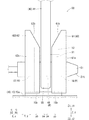
図1〜図7を参照して、図1に示す第1実施形態の着脱機構1について説明する。 With reference to FIGS. 1-7, the attachment / detachment mechanism 1 of 1st Embodiment shown in FIG. 1 is demonstrated.
着脱機構1は、建設機械に用いられる。着脱機構1が用いられる建設機械は、建設作業などの作業を行う機械であり、例えばクレーンであり、例えば掘削機などである。着脱機構1は、マスト30(連結部材)に取り付けられた取付部材40を本体10に取り付けるための機構である。着脱機構1は、本体10と、マスト30と、下部スプレッダ38と、取付部材40と、ガイド部材50と、を備える。
The detachment mechanism 1 is used for a construction machine. The construction machine in which the attachment / detachment mechanism 1 is used is a machine that performs work such as construction work, and is, for example, a crane, such as an excavator. The attachment / detachment mechanism 1 is a mechanism for attaching the
本体10は、下部走行体(図示なし)に対して旋回自在に取り付けられる上部旋回体である。本体10には、ブーム(図示なし)などが取り付けられる。ブームは、本体10に対して起伏可能に、本体10に取り付けられる。本体10は、本体フレーム11と、マストフットピン12と、下部スプレッダ連結部13と、本体側取付部15と、ピン21(図2参照)と、シリンダ23(図3参照)と、を備える。
The
本体フレーム11は、本体10を構成する構造物であり、長手方向を有する。本体フレーム11の長手方向を前後方向Xとする。前後方向Xにおいて、本体側取付部15からマストフットピン12に向かう側(または向き)を前側X1とし、その逆側を後側X2とする。前後方向Xに直交する水平方向を横方向Yとする。前後方向Xおよび横方向Yに直交する方向を上下方向Zとする。上下方向Zにおいて、本体フレーム11からマスト30に向かう側を上側Z1とし、その逆側を下側Z2とする。
The main body frame 11 is a structure that constitutes the
マストフットピン12(連結部材連結部)は、マスト30の基端部が連結されるピンであり、本体10に対するマスト30の回転軸となるピンである。マストフットピン12は、本体フレーム11の前側X1端部に設けられる。上記「端部」は、端およびその近傍を意味する(以下同様)。
The mast foot pin 12 (connecting member connecting portion) is a pin to which the proximal end of the
下部スプレッダ連結部13は、下部スプレッダ38が連結される部分であり、本体フレーム11の後側X2端部に設けられる。
The lower
本体側取付部15は、取付部材40が取り付けられ、取付部材40を支持する部分である。本体側取付部15には、例えば、取付部材40の前側X1部分が取り付けられる。本体側取付部15は、本体フレーム11の内部に設けられ、例えば本体フレーム11の前後方向Xにおける略中央部などに配置される。本体側取付部15は、支持フレーム15aと、図2に示す本体板部15bと、本体側ピン孔16と、を備える。
The main body
支持フレーム15aは、本体板部15bを介して取付部材40を下側Z2から支持する構造物である。図1に示すように、支持フレーム15aは、本体フレーム11に固定される。図2に示すように、本体板部15bは、板状であり、例えば支持フレーム15aから上側Z1に突出する。図3に示すように、本体板部15bは、本体10に取付部材40が取り付けられたとき、取付フレーム41(下記)を挟むように配置される。
The
本体側ピン孔16は、ピン21が差し込まれるピン孔である。本体側ピン孔16は、本体フレーム11に対して固定され、例えば、本体側取付部15に形成され、本体板部15bに形成される。なお、図1に示すように、取付部材40の前側X1部分以外の部分、例えば取付部材40の後側X2部分が取り付けられる本体側取付部17が設けられてもよい。
The main body
ピン21(図2参照)は、本体10と取付部材40とを連結および固定する。図3に示すように、ピン21は、本体側ピン孔16および取付部材側ピン孔46(下記)に差し込まれる。本体側ピン孔16および取付部材側ピン孔46を、ピン孔Hともいう。ピン21は、テーパ部21tを備える。テーパ部21tは、ピン21の先端側部分(先端部)に形成され、ピン21の先端側ほどピン21の直径が小さくなるように形成される。
The pins 21 (see FIG. 2) connect and fix the
シリンダ23(ピン着脱装置)は、ピン孔Hに対するピン21の着脱を行う装置である。シリンダ23は、本体フレーム11(図1参照)に取り付けられ、例えば支持フレーム15aに取り付けられる。シリンダ23は、本体側ピン孔16と横方向Yに対向するように、本体側ピン孔16と同軸に配置される。シリンダ23は、例えば油圧シリンダなどである。
The cylinder 23 (pin attaching and detaching device) is a device for attaching and detaching the
マスト30(連結部材)は、図1に示すように、本体10に対して移動可能に本体10に連結される。マスト30は、本体10に対して起伏可能に本体10に取り付けられる、起伏部材である。マスト30は、ブーム(図示なし)を起伏させる。マスト30は、主柱31と、マストフット33と、マスト側取付部35と、上部スプレッダ37と、を備える。
The mast 30 (connection member) is movably connected to the
主柱31は、箱型(中空)構造物である。マスト30は、いわば箱マストである。主柱31は、横方向Yに並ぶように、横方向Yに間隔をあけて、2本設けられる。マストフット33は、マスト30の基端部に設けられ、マストフットピン12に取り付けられる。
The
マスト側取付部35は、例えばピンを介して、取付部材40が取り付けられる部分である。マスト側取付部35は、2本の各主柱31に固定される。図5に示すように、マスト側取付部35は、取付フレーム41(下記)を横方向Yから挟むように構成される。図1に示すように、上部スプレッダ37は、主柱31の先端部に設けられ、複数の滑車を有する。
The mast
下部スプレッダ38は、複数の滑車を有する装置である。図7に示すように、下部スプレッダ38は、本体10に取り付けられ、下部スプレッダ連結部13に取り付けられる。下部スプレッダ38と、上部スプレッダ37とに、起伏ロープ(図示なし)が掛けられる。
The
取付部材40は、マスト30に着脱可能であり、かつ、本体10に着脱可能である。図1に示すように、取付部材40は、取付フレーム41と、ウインチ43と、取付部材側ピン孔46と、を備える。
The mounting
取付フレーム41は、ウインチ43を支持するフレームである。取付フレーム41は、ピンにより、マスト側取付部35に取り付け可能である。取付フレーム41は、ピン21(図2参照)により、本体側取付部15に取り付け可能である。取付フレーム41は、例えば、横方向Yからウインチ43を挟むように配置される板などを有する。
The mounting
ウインチ43は、ワイヤロープの巻取り、および繰出しを行う装置である。ウインチ43は、例えば、ブーム(図示なし)を起伏させるための起伏ロープを巻取りおよび繰出しする、起伏ウインチである。ウインチ43が起伏ロープを巻取りおよび操出しすることで、図7に示す下部スプレッダ38と上部スプレッダ37との間隔が変わり、本体10に対してマスト30が起伏する。マスト30とブームとはガイライン(ロープ、リンクなど)により接続されているため、マスト30が起伏する結果、ブームが起伏する。なお、ウインチ43は、起伏ロープ以外のロープを巻取りおよび操出するものであってもよい。
The
取付部材側ピン孔46は、図1に示すように、ピン21(図2参照)が差し込まれるピン孔であり、取付フレーム41に対して固定される。例えば、取付部材側ピン孔46は、取付フレーム41の前側X1端部かつ下側Z2端部に形成される。図3に示すように、ピン孔Hに差し込まれたピン21の軸方向をピン軸方向yとする。ピン軸方向yは、例えば横方向Yである。図2に示すように、本体10に対する取付部材40の着脱の方向を着脱方向zとする。着脱方向zは、例えば上下方向Zまたは略上下方向Zである。着脱方向zにおいて、本体10に取付部材40が取り付けられるときの、本体10に対する取付部材40の移動の向きを取り付け側z2とし、その逆側を取り外し側z1とする。取り付け側z2は、例えば下側Z2である。取り外し側z1は、例えば上側Z1である。着脱方向zおよびピン軸方向yに直交する方向を着脱直交方向xとする。着脱直交方向xは、前後方向Xまたは略前後方向Xである。
The mounting member
ガイド部材50は、本体10に対する取付部材40の位置をガイドする。ガイド部材50は、本体10および取付部材40に設けられる。ガイド部材50の少なくとも一部は、本体10および取付部材40に、溶接により固定される(製缶取付される)。ガイド部材50は、凸部51と、凹部53と、被挟み部55と、挟み部60と、を備える。以下では、図2および図6に示すように、本体10に取付部材40が取り付けられた状態(または略取り付けられた状態)について説明する。
The
凸部51および凹部53は、図2に示すように、本体10に取付部材40が取り付けられるときに、凹部53に凸部51が差し込まれるように構成される。凸部51および凹部53は、凹部53に凸部51が差し込まれたとき、本体側ピン孔16と取付部材側ピン孔46とのずれ(ピン孔Hのずれ)が、所定範囲内になるように構成される。この所定範囲は、ピン孔Hにピン21を差し込むことが可能な、ピン孔Hのずれの許容範囲である。
The
凸部51は、本体10および取付部材40のいずれかに設けられる。本実施形態では、凸部51は、本体10に設けられ、本体10に固定される。例えば、凸部51は、本体側取付部15に固定され、本体板部15bに固定され、本体板部15bと一体的に形成される。凸部51は、本体側ピン孔16の近傍に配置され、本体側ピン孔16よりも取り外し側z1に配置される。凸部51は、着脱方向zに凸状(突出する形状)であり、取り外し側z1に凸状である。例えば、凸部51は、ピン軸方向yから見たときに台形状である。凸部51は、凸部先端部51aと、凸部傾斜部51bと、を備える。
The
凸部先端部51aは、凸部51の先端側部分を構成する。凸部51の先端側は、取り外し側z1である。凸部先端部51aは、着脱直交方向xに延び、ピン軸方向yから見て直線状(略直線状を含む、以下同様)に延びる。
The
凸部傾斜部51bは、凸部先端部51aよりも、着脱直交方向xにおける両外側に形成される。凸部傾斜部51bは、凸部先端部51aよりも前側X1および後側X2に配置される。凸部傾斜部51bは、凸部51の先端側(取り外し側z1)ほど、凸部51の着脱直交方向xにおける幅が狭くなるように、着脱方向zに対して傾斜する。前側X1および後側X2それぞれの凸部傾斜部51bは、ピン軸方向yから見たとき、直線状に延びる。凸部傾斜部51bのうち凸部先端部51aよりも前側X1の部分の着脱方向zに対する傾斜角度と、同後側X2の部分の着脱方向zに対する傾斜角度とは、例えば同じであり、例えば異なってもよい。図2に示す例では、凸部傾斜部51bは、着脱方向zに対して約45°傾斜する。例えば、凸部傾斜部51bの取り付け側z2端部の着脱方向zにおける位置(着脱方向z位置)は、本体側ピン孔16の取り外し側z1端部の着脱方向z位置と同じ位置である。
The convex
凹部53は、本体10および取付部材40のうち、凸部51が設けられる側とは異なる側に設けられる。本実施形態では、凹部53は、取付部材40に設けられ、取付部材40に固定され、取付フレーム41に固定される。凹部53は、取付部材側ピン孔46の近傍に配置され、取付部材側ピン孔46よりも取り外し側z1に配置される。凹部53は、着脱方向zに凹状(凹んだ形状)であり、取り外し側z1に凹状である。本体10に取付部材40が取り付けられるときに、凸部51が凹部53に差し込まれるように、凹部53が構成される。例えば、図3に示すように、凹部53のピン軸方向yの幅は、凸部51のピン軸方向yの幅よりも広い。図2に示すように、凹部53は、凹部底部53aと、凹部傾斜部53bと、を備える。
The
凹部底部53aは、凹部53の底側部分を構成する。凹部53の底側は、取り外し側z1である。凹部底部53aは、着脱直交方向xに延び、例えば、ピン軸方向yから見て直線状に延びる。凹部底部53aは、凹部53に凸部51が差し込まれたときに、凸部先端部51aに当たることが可能に構成される(配置および形成される)。凹部底部53aの着脱直交方向xにおける幅は、凸部先端部51aの着脱直交方向xにおける幅よりも広い。よって、本体10に対する取付部材40の着脱直交方向xの移動が、凸部傾斜部51bと凹部傾斜部53bとが当たらない限り、許容される。
The
凹部傾斜部53bは、凹部53の着脱直交方向xにおける両側部分(前側X1および後側X2)に形成される。凹部傾斜部53bは、凹部53の底側(取り外し側z1)ほど、凹部53の着脱直交方向xにおける隙間(凸部51を差し込み可能な空間)が狭くなるように、着脱方向zに対して傾斜する。凹部傾斜部53bは、凹部53に凸部51が差し込まれたときに、凸部傾斜部51bに当たることが可能に構成される(配置および形成される)。前側X1および後側X2それぞれの凹部傾斜部53bは、ピン軸方向yから見たとき、直線状に延びる。凹部傾斜部53bの着脱方向zに対する傾斜角度は、凸部傾斜部51bの着脱方向zに対する傾斜角度と、例えば同じであり、例えば異なってもよい。
The
被挟み部55は、本体10および取付部材40のいずれかに設けられる。本実施形態では、被挟み部55は、取付部材40に設けられる。図4に示すように、被挟み部55は、着脱方向zに延びる。被挟み部55は、着脱直交方向xに延びる。例えば、被挟み部55は、取付フレーム41と一体的に構成され、取付フレーム41の一部を構成する。
The
挟み部60は、被挟み部55をピン軸方向yから挟むように構成される。挟み部60は、本体10および取付部材40のうち被挟み部55が設けられる側とは異なる側に設けられる。本実施形態では、挟み部60は、本体10に設けられ、本体10に固定される。例えば、挟み部60は、本体側取付部15に固定され、支持フレーム15aに固定される。例えば、図2に示すように、挟み部60は、本体板部15bに直接固定される。挟み部60は、本体板部15bに直接固定されなくてもよく、本体板部15bから離れた位置に設けられてもよい。図4に示すように、挟み部60は、第一挟み部61と、第二挟み部62と、を備える。ピン軸方向yにおいて、挟み部60から、挟み部60の隙間に向かう側を、挟み部内側yaとする。挟み部60の隙間から挟み部60に向かう側を挟み部外側ybとする。
The pinching
第一挟み部61は、被挟み部55に対して、ピン軸方向yの一方側(図4では右側)に配置される。第一挟み部61は、例えば柱状の第一挟み部本体部61aと、第一挟み部傾斜部61bと、を備える。第一挟み部本体部61aの挟み部内側yaの端は、本体板部15bの挟み部内側yaの端と揃うように配置される(第二挟み部本体部62aも同様)。第一挟み部傾斜部61bは、第一挟み部61の取り外し側z1端部に設けられる。第一挟み部傾斜部61bは、取り付け側z2ほど挟み部内側yaに配置されるように、着脱方向zに対して傾斜する。第一挟み部傾斜部61bは、着脱直交方向xから見て直線状に延びる。
The
第二挟み部62は、被挟み部55に対して第一挟み部61が配置される側とは反対側(図4では左側)に配置される。第一挟み部61と第二挟み部62とで被挟み部55を挟むように、第一挟み部61および第二挟み部62が配置される。第二挟み部62は、例えば第一挟み部61とピン軸方向yに対称に(左右対称に)構成され、例えば左右対称に構成されなくてもよい。第一挟み部61と第二挟み部62とは、ピン軸方向yに対向するように配置される。第一挟み部61と第二挟み部62とは、ピン軸方向yに対向しなくてもよく、着脱直交方向xにずれてもよい。第二挟み部62は、例えば柱状の第二挟み部本体部62aと、第二挟み部傾斜部62bと、を備える。第二挟み部傾斜部62bは、第二挟み部62の取り外し側z1端部に設けられる。第二挟み部傾斜部62bは、取り付け側z2ほど挟み部内側yaに配置されるように、着脱方向zに対して傾斜する。
The
(作動)
図1に示す着脱機構1の作動の概要は次の通りである。建設機械の組立時には、取付部材40が取り付けられたマスト30が、本体10に取り付けられる。次に、図6に示すように、取付部材40が本体10に取り付けられる。次に、図7に示すように、取付部材40がマスト30から取り外される。また、建設機械の分解時には、取付部材40が、本体10から取り外され、図1に示すようにマスト30に取り付けられる。この作動の詳細は次の通りである。
(Operation)
The outline of the operation of the mounting and demounting mechanism 1 shown in FIG. 1 is as follows. At the time of assembly of the construction machine, the
(マスト30の本体10への取り付け)
建設機械の組立前の着脱機構1の状態は次の通りである。マスト30は、本体10から取り外されている。取付部材40は、マスト30に取り付けられている。取付フレーム41は、マスト側取付部35に取り付けられている。この状態から、マスト30が、次のように本体10に取り付けられる。マスト30が、組立用クレーンなど(図示なし)で吊り上げられ、本体10に取り付けられる。このとき、マストフット33が、マストフットピン12で固定される。このとき、マスト30の先端部が、マストフット33よりも上側Z1かつ後側X2に配置されるように、マスト30が本体10に対して起こされた状態とされる。このときの、本体10の上面に対するマスト30の角度は、例えば約10°などである。
(Attachment of the
The state of the detaching mechanism 1 before assembly of the construction machine is as follows. The
(取付部材40の本体10への取り付け)
次に、マスト30が、マストフットピン12を中心に倒伏(回転)させられる。このときのマスト30の倒伏の向きは、マスト30の先端部が下側Z2に移動する向きである。マスト30の倒伏に伴い、取付部材40が、マストフットピン12を中心に下側Z2に回転する。すると、本体10に対する取付部材40の位置が、図2に示すガイド部材50にガイドされる。このガイドには、被挟み部55および挟み部60によるガイドと、凸部51および凹部53によるガイドと、がある。
(Attachment of mounting
The
図5に示す被挟み部55および挟み部60によるガイドは次のように行われる。被挟み部55が、取り付け側z2に移動し、挟み部60に近づく。このとき、被挟み部55が隙間C1(詳細は下記)に対してピン軸方向yにずれている場合、被挟み部55の取り付け側z2端部が、第一挟み部傾斜部61bまたは第二挟み部傾斜部62bに当たり、挟み部内側yaに移動する。このように、被挟み部55のピン軸方向yの位置がガイド(規制)される。そして、被挟み部55が、挟み部60の隙間C1に差し込まれる。その結果、本体10に対する取付部材40のピン軸方向yの位置が、所定位置に位置決めされる。
The guide by the
図2に示す凸部51および凹部53によるガイドは次のように行われる。凹部53が、取り付け側z2に移動し、凸部51に近づく。このとき、凸部51に対する凹部53の位置が着脱直交方向xにずれている場合、凹部傾斜部53bが、凸部傾斜部51bに当たり、凸部傾斜部51bに対してスライドする。このように、凸部51に対する凹部53の着脱直交方向xの位置がガイドされる。その結果、本体10に対する取付部材40の、着脱直交方向xの位置がガイドされる。また、凹部53が取り付け側z2に移動すると、凹部底部53aが凸部先端部51aに当たる。よって、凸部51に対する凹部53の、取り付け側z2への移動が規制される。その結果、本体10に対する取付部材40の、着脱方向zの位置が規制(ガイド)される。その結果、本体側ピン孔16と取付部材側ピン孔46とのずれ(ピン孔Hのずれ)が所定範囲内になる(収まる)。このように、図1に示すマストフットピン12を中心にマスト30を倒伏させると、自動的に、図2に示すピン孔Hのずれが所定範囲内になる。
The guide by the
図3に示す凹部底部53aが凸部先端部51aに当たっているとき、取付部材側ピン孔46の中心軸は、本体側ピン孔16の中心軸よりも取り付け側z2に配置される。この状態で、ピン21が、シリンダ23により(シリンダ23の推力を利用して)、ピン孔Hに差し込まれる。すると、テーパ部21tが、取付部材側ピン孔46に当たり、取付部材側ピン孔46を取り外し側z1に移動させる(押し上げる、持ち上げる)。すると、本体側ピン孔16の中心軸と取付部材側ピン孔46の中心軸とがあう(同軸または略同軸になる)。そして、ピン21がピン孔Hに完全に差し込まれる。その結果、図2に示すように、凹部53と凸部51との間に、着脱方向zの隙間(若干のクリアランス)が生じる。その結果、本体側取付部15に取付部材40が取り付けられる。なお、図1に示すように、本体側取付部15と同様の本体側取付部17が設けられる場合は、取付部材40が、本体側取付部17に取り付けられる。
When the recessed
本実施形態とは異なり、図3に示す凹部底部53aが凸部先端部51aに当たっているときに、取付部材側ピン孔46の中心軸が、本体側ピン孔16の中心軸よりも取り外し側z1に配置された場合は(図示なし)、ピン21をピン孔Hに差し込めない。なぜなら、凹部底部53aが凸部先端部51aに当たっているときには、本体10に対して取付部材40が取り付け側z2に移動できないので、本体側ピン孔16に対して取付部材側ピン孔46が取り付け側z2に移動できないからである。
Unlike the present embodiment, when the recessed
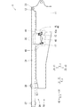
(取付部材40のマスト30からの取り外し)
図6に示すように、本体側取付部15に取付部材40が取り付けられた後、取付部材40が、マスト側取付部35から取り外される。例えば、図5に示す取付フレーム41とマスト側取付部35とを連結するピンが外される。
(Removal of mounting
As shown in FIG. 6, after the mounting
図6に示すように、取付部材40が、本体側取付部15に取り付けられるのと同様に、下部スプレッダ38が、下部スプレッダ連結部13に取り付けられる。また、下部スプレッダ38が、主柱31から取り外される。なお、主柱31と下部スプレッダ38とがリンクを介して接続される場合に、リンクが本体10などに格納されてもよい。その後、図7に示すように、本体10に対してマスト30が起こされる。
As shown in FIG. 6, the
(マスト30への取付部材40の取り付け)
建設機械の分解時には、図6に示すように、マスト30が倒伏させられる。そして、取付部材40が、本体10から取り外され、マスト30に取り付けられる。このとき、図5に示す取付フレーム41が、マスト側取付部35に差し込まれる。そして、取付フレーム41とマスト側取付部35とがピンにより接続される。その結果、取付部材40がマスト側取付部35に取り付けられる。また、図6に示す下部スプレッダ38が、下部スプレッダ連結部13から取り外され、主柱31に取り付けられる。
(Mounting of the mounting
At the time of disassembly of the construction machine, as shown in FIG. 6, the
(挟み部60などの隙間について)
図5に示す挟み部60などの隙間について説明する。以下では、ピン軸方向yから見た場合について説明する。隙間には、隙間C1と、隙間C2と、隙間C3と、がある。隙間C1は、第一挟み部本体部61aと第二挟み部本体部62aとの、ピン軸方向yの隙間である。隙間C2は、マスト側取付部35の、取付フレーム41を挟む部分の、ピン軸方向yの隙間である。隙間C3は、第一挟み部傾斜部61bの取り外し側z1端部と、第二挟み部傾斜部62bの取り外し側z1端部と、のピン軸方向yの隙間である。
(About the gap of the pinching
The clearance of the pinching
隙間C1の大きさは、被挟み部55のピン軸方向yの寸法(厚さ)よりも大きく設定される。ここで、本体10への挟み部60の取付(溶接)位置に誤差が生じると、隙間C1の大きさに誤差が生じる。そこで、隙間C2および隙間C3は、隙間C1の公差が最大(最悪)の状態を考慮して設定される。例えば、隙間C2は、理想的な隙間C1と、隙間C1の最大の公差と、の和(またはそれ以上)に設定される。この隙間C2の設定により、図4に示す本体側取付部15に取り付けられた取付フレーム41を、図5に示すマスト側取付部35に近づけたときに、取付フレーム41がマスト側取付部35に干渉することを抑制できる。また、隙間C2の設定と同様に、隙間C3は、理想的な隙間C2と、隙間C2の最大の公差と、の和(またはそれ以上)に設定される。この隙間C3の設定により、マスト側取付部35に取り付けられた取付フレーム41を、本体側取付部15に近づけたときに、被挟み部55が挟み部60に引っ掛かることを抑制できる。このときに、被挟み部55が挟み部60に引っ掛かり、本体側取付部15に対して取付フレーム41が取り付け側z2に移動不可能となることを抑制できる。
The size of the gap C1 is set larger than the dimension (thickness) of the
本実施形態とは異なり、第一挟み部傾斜部61bおよび第二挟み部傾斜部62bが設けられない場合(隙間C3が隙間C1と等しい場合)は、次の問題が生じる場合がある。この場合、隙間C1および隙間C2のうち狭い方で、部材どうしの干渉のおそれがある。例えば、隙間C2よりも隙間C1が狭い場合、マスト側取付部35に取り付けられた取付フレーム41を本体側取付部15に近づけたときに、被挟み部55が挟み部60に干渉するおそれがある。例えば、隙間C1よりも隙間C2が狭い場合、本体側取付部15に取り付けられた取付フレーム41をマスト側取付部35に近づけたときに、取付フレーム41がマスト側取付部35に干渉するおそれがある。一方、本実施形態では、これらの干渉を抑制できる。よって、干渉を抑制するために隙間C1および隙間C2を広げる必要がない。
Unlike the present embodiment, when the first pinched portion
(第1の発明の効果)
図1に示す着脱機構1による効果は次の通りである。着脱機構1は、本体10と、マスト30と、取付部材40と、ガイド部材50と、を備える。本体10は、建設機械の上部本体であり、本体側ピン孔16(図2参照)を有する。マスト30は、本体10に対して移動可能に本体10に連結される。取付部材40は、マスト30に着脱可能であり、本体10に着脱可能であり、図2に示す取付部材側ピン孔46を有する。ガイド部材50は、本体10に対する取付部材40の位置をガイドする。本体10に対する取付部材40の着脱の方向を着脱方向zとする。本体側ピン孔16および取付部材側ピン孔46に差し込まれるピン21の軸方向をピン軸方向yとする。着脱方向zおよびピン軸方向yに直交する方向を着脱直交方向xとする。ガイド部材50は、凸部51と、凹部53と、を備える。凸部51は、本体10および取付部材40のいずれかに設けられ、着脱方向zに凸状である。凹部53は、本体10および取付部材40のうち凸部51が設けられる側とは異なる側に設けられる。本体10に取付部材40が取り付けられるときに、凸部51が凹部53に差し込まれる。凸部51は、凸部先端部51aと、凸部傾斜部51bと、を備える。凹部53は、凹部底部53aと、凹部傾斜部53bと、を備える。
(Effect of the first invention)
The effects of the mounting and demounting mechanism 1 shown in FIG. 1 are as follows. The mounting and demounting mechanism 1 includes a
[構成1−1]凸部先端部51aは、凸部51の先端側部分を構成する。
[構成1−2]凸部傾斜部51bは、凸部先端部51aよりも着脱直交方向xにおける両外側に形成され、凸部51の先端側(取り外し側z1)ほど凸部51の着脱直交方向xにおける幅が狭くなるように、着脱方向zに対して傾斜する。
[構成1−3]凹部底部53aは、凹部53の底側部分を構成し、凹部53に凸部51が差し込まれたときに凸部先端部51aが当たることが可能に構成される。
[構成1−4]凹部傾斜部53bは、凹部底部53aよりも着脱直交方向xにおける両外側に形成され、凹部53の底側(取り外し側z1)ほど凹部53の着脱直交方向xにおける隙間が狭くなるように着脱方向zに対して傾斜する。凹部傾斜部53bは、凹部53に凸部51が差し込まれたときに凸部傾斜部51bに当たることが可能に構成される。
[構成1−5]凸部51および凹部53は、凹部53に凸部51が差し込まれたとき、本体側ピン孔16と取付部材側ピン孔46とのずれが所定範囲内になるように構成される。
[Structure 1-1] The convex portion
[Configuration 1-2] The convex portion
[Configuration 1-3] The
[Configuration 1-4] The
[Configuration 1-5] The
主に上記[構成1−1]および[構成1−3]により、本体10に取付部材40が取り付けられるときに、凹部53に凸部51が差し込まれ、凸部先端部51aが凹部底部53aに当たる。よって、本体10に対する取付部材40の、着脱方向zの移動および位置がガイド(規制)される。また、上記[構成1−2]および[構成1−4]により、本体10に取付部材40が取り付けられるときに、凹部53に凸部51が差し込まれ、凹部傾斜部53bと凸部傾斜部51bとが当たる。よって、本体10に対する取付部材40の着脱直交方向xの移動および位置がガイドされる。よって、上記[構成1−1]〜[構成1−5]により、本体10に取付部材40が取り付けられると、本体側ピン孔16と取付部材側ピン孔46とのずれが所定範囲内(ピン21を差し込むことが可能な許容範囲内)になる。よって、ピン孔Hの位置合わせに必要な時間および手間を抑制できる。
When the mounting
上記の効果が得られる結果、次の効果が得られる場合がある。図1に示す取付部材40は、マスト30に着脱可能であり、本体10に着脱可能である。よって、取付部材40がマスト30に取り付けられた状態で、取付部材40を本体10に取り付けることができる。ここで、マスト30に取り付けられた状態の取付部材40を本体10に取り付ける場合は、マスト30から取り外された状態の取付部材40を本体10に取り付ける場合に比べ、本体10に対する取付部材40の位置を調整しにくい。しかし、本実施形態の着脱機構1では、本体10に対する取付部材40の位置がガイド部材50によりガイドされる。よって、取付部材40がマスト30に取り付けられた状態でも、ピン孔H(図2参照)の位置を合わせやすい。なお、取付部材40がマスト30から取り外された状態で、取付部材40が本体10に取り付けられてもよい。
As a result of obtaining the above effects, the following effects may be obtained. The mounting
(第2の発明の効果)
[構成2]図2に示すガイド部材50(少なくとも一部)は、本体10および取付部材40に、溶接により固定される。
(Effect of the second invention)
[Configuration 2] The guide member 50 (at least a part) shown in FIG. 2 is fixed to the
上記[構成2]により、ガイド部材50に負荷が掛かっても、本体10および取付部材40に対して、ガイド部材50がずれない。よって、ガイド部材50を用いたピン孔Hの位置合わせを確実に(毎回、スムーズに)行える。よって、ピン孔Hの位置合わせに必要な時間および手間を抑制できる。
According to the above [Configuration 2], even when a load is applied to the
この効果の詳細は次の通りである。例えば、ガイド部材50が、ボルトなどの締結部材により、本体10および取付部材40の少なくともいずれかに固定された場合は次の問題がある。この場合、本体10に対する取付部材40の着脱時、および、輸送時の振動などにより、ガイド部材50に負荷がかかり、本体10または取付部材40に対するガイド部材50の位置や角度がずれるおそれがある。そのため、本体10に取付部材40が取り付けられるときに、本体側ピン孔16と取付部材側ピン孔46とのずれが所定範囲内に収まらず、ピン孔Hにピン21を挿入できなくなるおそれがある。そのため、ピン孔Hにピン21を挿入できるように、本体10または取付部材40に対するガイド部材50の位置を調整する必要が生じ、時間および手間がかかる。
The details of this effect are as follows. For example, when the
(第3の発明の効果)
[構成3]凹部底部53aは、着脱直交方向xに延びる。凹部底部53aの着脱直交方向xにおける幅は、凸部先端部51aの着脱直交方向xにおける幅よりも広い。
(Effect of the third invention)
[Configuration 3] The
上記[構成3]により、凹部53に凸部51が差し込まれた状態のときに、凹部53に対して凸部51が着脱直交方向xに移動可能となる。
By the above [Configuration 3], when the
(第4の発明の効果)
[構成4]凸部先端部51aは、着脱直交方向xに延びる。
(Effect of the fourth invention)
[Configuration 4] The
上記[構成3]および[構成4]により、凹部53に凸部51が差し込まれた状態のときに、凹部53に対して凸部51を着脱直交方向xに容易に移動させることができる。
By the above [Configuration 3] and [Configuration 4], when the
(第5の発明の効果)
図3に示すように、着脱方向zにおいて、本体10に取付部材40を取り付けるときの本体10に対する取付部材40の移動の向きを取り付け側z2とする。ピン21は、ピン21の先端部に形成されるテーパ部21tを備える。
[構成5]凹部底部53aが凸部先端部51aに当たっているとき、取付部材側ピン孔46の中心軸は、本体側ピン孔16の中心軸よりも取り付け側z2に配置される。
(Effects of the fifth invention)
As shown in FIG. 3, the direction of movement of the mounting
[Configuration 5] When the recessed
着脱機構1は、上記[構成5]を備える。よって、ピン孔Hにピン21を差し込もうとしたとき、テーパ部21tが取付部材側ピン孔46を取り付け側z2とは反対側(取り外し側z1)に移動させることができる。よって、本体側ピン孔16の中心軸と取付部材側ピン孔46の中心軸との位置を合わせることができ、ピン孔Hにピン21を差し込むことができる。
The mounting and demounting mechanism 1 includes the above [Configuration 5]. Therefore, when trying to insert the
(第6の発明の効果)
図4に示すように、ガイド部材50は、被挟み部55と、挟み部60と、を備える。
[構成6]被挟み部55は、本体10および取付部材40のいずれかに設けられ、着脱方向zに延びる。挟み部60は、本体10および取付部材40のうち被挟み部55が設けられる側とは異なる側に設けられる。挟み部60は、本体10に取付部材40が取り付けられるときに被挟み部55が差し込まれ、被挟み部55をピン軸方向yから挟むように構成される。
(Effect of the sixth invention)
As shown in FIG. 4, the
[Configuration 6] The pinched
上記[構成6]により、被挟み部55が挟み部60に挟まれることで、本体10に対する取付部材40の、ピン軸方向yの位置をガイドできる。よって、本体10への取付部材40の取り付けを容易に行える。
According to the above [Configuration 6], when the
(第7の発明の効果)
挟み部60は、第一挟み部61と、第二挟み部62と、を備える。第一挟み部61は、被挟み部55に対してピン軸方向yの一方側に配置される。第二挟み部62は、被挟み部55に対して第一挟み部61が配置される側とは反対側に配置される。着脱方向zにおいて、本体10に取付部材40を取り付けるときの本体10に対する取付部材40の移動の向きを取り付け側z2とする。ピン軸方向yにおいて、挟み部60から挟み部60の隙間に向かう側を挟み部内側yaとする。
(Effect of the seventh invention)
The pinching
[構成7]第一挟み部61は、取り付け側z2ほど挟み部内側yaに配置されるように着脱方向zに対して傾斜する第一挟み部傾斜部61bを備える。第二挟み部62は、取り付け側z2ほど挟み部内側yaに配置されるように着脱方向zに対して傾斜する第二挟み部傾斜部62bを備える。
[Configuration 7] The
着脱機構1は、上記[構成7]を備える。よって、本体10に取付部材40が取り付けられるときに、第一挟み部傾斜部61bおよび第二挟み部傾斜部62bの少なくともいずれかに被挟み部55が当たった場合、被挟み部55が挟み部内側yaに移動しやすい。よって、被挟み部55が挟み部60に差し込まれやすい。
The mounting and demounting mechanism 1 includes the above [Configuration 7]. Therefore, when the
(第2実施形態)
図8を参照して第2実施形態の着脱機構201について、第1実施形態との相違点を説明する。図4に示すように、第1実施形態では、第一挟み部傾斜部61bと第二挟み部傾斜部62bとの着脱方向zにおける位置は、同じ位置であった。一方、図8に示すように、第2実施形態では、第二挟み部傾斜部262bは、第一挟み部傾斜部261bよりも取り付け側z2に配置される。第二挟み部傾斜部262bの取り外し側z1端部は、第一挟み部傾斜部261bの取り外し側z1端部よりも、取り付け側z2に配置される。第二挟み部傾斜部262bの取り付け側z2端部は、第一挟み部傾斜部261bの取り付け側z2端部よりも、取り付け側z2に配置される。
Second Embodiment
The difference between the first embodiment and the attachment /
(第8の発明の効果)
図8に示す着脱機構201による効果は次の通りである。
[構成8]第二挟み部傾斜部262bは、第一挟み部傾斜部261bよりも取り付け側z2に配置される。
(Effect of the eighth invention)
The effects of the attachment /
[Configuration 8] The second pinched portion
上記[構成8]により、被挟み部55が挟み部60の間に差し込まれやすい。さらに詳しくは、図4に示すように第一挟み部傾斜部61bと第二挟み部傾斜部62bとの着脱方向zにおける位置が同じである場合は、次の問題が生じる場合がある。例えば、本体10に取付部材40を取り付けるときに、被挟み部55が、第一挟み部本体部61aに当たる。すると、被挟み部55が、第二挟み部傾斜部62b側に移動し、第二挟み部傾斜部62bに当たる。すると、被挟み部55が、第一挟み部傾斜部61b側に移動し、第一挟み部傾斜部61bに当たる。このように、被挟み部55が、第一挟み部傾斜部61bと第二挟み部傾斜部62bとに当たるので、被挟み部55が挟み部60の間に差し込まれにくい場合がある。一方、上記[構成8]では、上記の問題が抑制される。よって、図8に示す被挟み部55が挟み部60の間に差し込まれやすい。
According to the above [Configuration 8], the
(変形例)
上記実施形態の構成要素の配置、形状、および数などが変更されてもよい。構成要素の一部が設けられなくてもよい。構成要素どうしの固定は、直接でも間接でもよい。構成要素どうしの連結は、直接でも間接でもよい。例えば、上記実施形態が下記のように変更されてもよい。
(Modification)
The arrangement, the shape, the number, and the like of the components of the above embodiment may be changed. Some of the components may not be provided. Fixing of components may be direct or indirect. The connection of components may be direct or indirect. For example, the above embodiment may be modified as follows.
着脱直交方向x、ピン軸方向y、および着脱方向zは、上記実施形態では、それぞれ、前後方向X、横方向Y、上下方向Zと一致(または略一致)した。しかし、着脱直交方向xは前後方向Xでなくてもよく、ピン軸方向yは横方向Yでなくてもよく、着脱方向zは上下方向Zでなくてもよい。 The attachment / detachment orthogonal direction x, the pin axis direction y, and the attachment / detachment direction z coincide (or substantially coincide) with the longitudinal direction X, the lateral direction Y, and the vertical direction Z, respectively, in the above embodiment. However, the attachment / detachment orthogonal direction x may not be the longitudinal direction X, the pin axis direction y may not be the lateral direction Y, and the attachment / detachment direction z may not be the vertical direction Z.
図1に示す本体10に連結される連結部材は、上記実施形態ではマスト30であったが、マスト30でなくてもよい。取付部材40は、上記実施形態ではウインチ43を有したが、ウインチ43を有さなくてもよい。連結部材および本体10に着脱可能な「取付部材」は、取付部材40でなくてもよく、例えば下部スプレッダ38などでもよい。なお、下部スプレッダ38には、本体10に対して横方向Yの軸回りに回転可能なものと、回転不可能なものとがある。そのうち、本体10に対して横方向Yの軸回りに回転不可能な下部スプレッダ38に、図2に示す凸部51および凹部53を含むガイド部材50を適用してもよい。
The connecting member connected to the
上記実施形態では、凸部51および挟み部60が本体10に設けられ、凹部53および被挟み部55が取付部材40に設けられた。一方、凸部51が取付部材40に設けられ、凹部53が本体10に設けられてもよい。また、被挟み部55が本体10に設けられ、挟み部60が取付部材40に設けられてもよい。上記実施形態では、凸部51は取り外し側z1に凸状、かつ、凹部53は取り外し側z1に凹状であった。一方、凸部51は取り付け側z2に凸状、かつ、凹部53は取り付け側z2に凹状でもよい。
In the embodiment, the
凸部51は、上記実施形態ではピン軸方向yから見て台形状であったが、三角形状(略三角形状を含む)などでもよい。本体側ピン孔16は、上記実施形態では本体10側のガイド部材50(凸部51)の近傍に配置されたが、本体10側のガイド部材50の近傍に配置されなくてもよい。
The
図1に示す例では、本体側取付部15が取付部材40の前側X1端部を支持し、本体側取付部17が取付部材40の後側X2端部を支持した。一方、本体10に対して取付部材40を支持する部材の構成(配置、数など)は、変更されてもよい。
In the example shown in FIG. 1, the main body
1、201 着脱機構
10 本体
16 本体側ピン孔
21 ピン
21t テーパ部
30 マスト(連結部材)
40 取付部材
46 取付部材側ピン孔
50 ガイド部材
51 凸部
51a 凸部先端部
51b 凸部傾斜部
53 凹部
53a 凹部底部
53b 凹部傾斜部
55 被挟み部
60 挟み部
61 第一挟み部
61b、261b 第一挟み部傾斜部
62 第二挟み部
62b、262b 第二挟み部傾斜部
y ピン軸方向
ya 挟み部内側
z 着脱方向
z2 取り付け側
1, 201 Attachment /
40 mounting
Claims (8)
前記本体に対して移動可能に前記本体に連結される連結部材と、
前記連結部材に着脱可能であり、前記本体に着脱可能であり、取付部材側ピン孔を有する取付部材と、
前記本体に対する前記取付部材の位置をガイドするガイド部材と、
を備え、
前記本体に対する前記取付部材の着脱の方向を着脱方向とし、
前記本体側ピン孔および前記取付部材側ピン孔に差し込まれるピンの軸方向をピン軸方向とし、
着脱方向およびピン軸方向に直交する方向を着脱直交方向とし、
前記ガイド部材は、
前記本体および前記取付部材のいずれかに設けられ、着脱方向に凸状の凸部と、
前記本体および前記取付部材のうち前記凸部が設けられる側とは異なる側に設けられ、前記本体に前記取付部材が取り付けられるときに前記凸部が差し込まれる凹部と、
を備え、
前記凸部は、
前記凸部の先端側部分を構成する凸部先端部と、
前記凸部先端部よりも着脱直交方向における両外側に形成され、前記凸部の先端側ほど前記凸部の着脱直交方向における幅が狭くなるように、着脱方向に対して傾斜する凸部傾斜部と、
を備え、
前記凹部は、
前記凹部の底側部分を構成し、前記凹部に前記凸部が差し込まれたときに前記凸部先端部が当たることが可能に構成される凹部底部と、
前記凹部底部よりも着脱直交方向における両外側に形成され、前記凹部の底側ほど前記凹部の着脱直交方向における隙間が狭くなるように着脱方向に対して傾斜し、前記凹部に前記凸部が差し込まれたときに前記凸部傾斜部に当たることが可能に構成される凹部傾斜部と、
を備え、
前記凸部および前記凹部は、前記凹部に前記凸部が差し込まれたとき、前記本体側ピン孔と前記取付部材側ピン孔とのずれが所定範囲内になるように構成され、
着脱直交方向における両側の前記凸部傾斜部、および着脱直交方向における両側の前記凹部傾斜部のそれぞれは、ピン軸方向から見て直線状に延び、
着脱方向に対する前記凹部傾斜部の傾斜角度は、着脱方向に対する前記凸部傾斜部の傾斜角度と同じである、
着脱機構。 A body having a body side pin hole which is an upper body of the construction machine;
A connecting member movably connected to the main body with respect to the main body;
A mounting member which is removable from the connecting member, removable from the main body, and having a mounting member side pin hole;
A guide member for guiding the position of the mounting member relative to the main body;
Equipped with
The mounting and demounting direction of the mounting member with respect to the main body is a mounting and demounting direction,
The axial direction of the pin inserted into the main body side pin hole and the mounting member side pin hole is taken as the pin axial direction,
The direction perpendicular to the mounting and demounting direction and the pin axis direction is the mounting and demounting direction,
The guide member is
A convex portion which is provided on any of the main body and the mounting member and which is convex in the mounting and demounting direction;
A concave portion provided on the side different from the side on which the convex portion is provided among the main body and the mounting member, and a concave portion into which the convex portion is inserted when the mounting member is attached to the main body;
Equipped with
The convex portion is
A protrusion tip end portion that constitutes a tip end side portion of the protrusion;
A convex portion inclined portion which is formed on both outer sides in the mounting / demounting orthogonal direction than the front end portion of the projection, and is inclined with respect to the mounting / demounting direction such that the width of the projection in the mounting / demounting orthogonal direction becomes narrower toward the front end side of the projection. When,
Equipped with
The recess is
A recess bottom portion which constitutes a bottom side portion of the recess and is configured such that the tip end of the protrusion can hit when the protrusion is inserted into the recess;
The recess is formed at both outer sides in the mounting and demounting orthogonal direction than the recess bottom, and the recess is inclined with respect to the mounting and removing direction so that the gap in the mounting and demounting orthogonal direction becomes narrower toward the bottom of the recess. A recess slope configured to be able to hit the protrusion slope when being
Equipped with
The convex portion and the concave portion are configured such that when the convex portion is inserted into the concave portion, the displacement between the main body side pin hole and the attachment member side pin hole falls within a predetermined range .
Each of the convex sloped portion on both sides in the mounting and demounting orthogonal direction and the concaved sloped portion on both sides in the mounting and demounting orthogonal direction extend linearly as viewed from the pin axial direction,
The inclination angle of the recessed portion inclined portion with respect to the mounting and demounting direction is the same as the inclination angle of the convex portion inclined portion with respect to the mounting and demounting direction
Detachment mechanism.
前記ガイド部材は、前記本体および前記取付部材に、溶接により固定される、
着脱機構。 The detaching mechanism according to claim 1, wherein
The guide member is fixed to the main body and the attachment member by welding.
Detachment mechanism.
前記凹部底部は、着脱直交方向に延び、
前記凹部底部の着脱直交方向における幅は、前記凸部先端部の着脱直交方向における幅よりも広い、
着脱機構。 It is an attachment or detachment mechanism of Claim 1 or 2, Comprising:
The recess bottom extends in the mounting / demounting direction,
The width of the recess bottom portion in the mounting / demounting orthogonal direction is wider than the width in the mounting / demounting direction of the tip of the projection.
Detachment mechanism.
前記凸部先端部は、着脱直交方向に延びる、
着脱機構。 The detaching mechanism according to claim 3, wherein
The tip of the convex portion extends in the mounting / demounting orthogonal direction.
Detachment mechanism.
着脱方向において、前記本体に前記取付部材を取り付けるときの前記本体に対する前記取付部材の移動の向きを取り付け側とし、
前記ピンは、前記ピンの先端部に形成されるテーパ部を備え、
前記凹部底部が前記凸部先端部に当たっているとき、前記取付部材側ピン孔の中心軸は、前記本体側ピン孔の中心軸よりも取り付け側に配置される、
着脱機構。 It is the attachment or detachment mechanism of any one of Claims 1-4, Comprising:
In the mounting and demounting direction, the direction of movement of the mounting member relative to the main body when mounting the mounting member to the main body is a mounting side,
The pin includes a tapered portion formed at the tip of the pin,
The central axis of the mounting member side pin hole is disposed on the mounting side relative to the central axis of the main body side pin hole when the recess bottom portion is in contact with the tip end portion of the convex portion.
Detachment mechanism.
前記本体に対して移動可能に前記本体に連結される連結部材と、
前記連結部材に着脱可能であり、前記本体に着脱可能であり、取付部材側ピン孔を有する取付部材と、
前記本体に対する前記取付部材の位置をガイドするガイド部材と、
を備え、
前記本体に対する前記取付部材の着脱の方向を着脱方向とし、
前記本体側ピン孔および前記取付部材側ピン孔に差し込まれるピンの軸方向をピン軸方向とし、
着脱方向およびピン軸方向に直交する方向を着脱直交方向とし、
前記ガイド部材は、
前記本体および前記取付部材のいずれかに設けられ、着脱方向に延びる被挟み部と、
前記本体および前記取付部材のうち前記被挟み部が設けられる側とは異なる側に設けられ、前記本体に前記取付部材が取り付けられるときに前記被挟み部が差し込まれ、前記被挟み部をピン軸方向から挟むように構成される挟み部と、
前記本体および前記取付部材のいずれかに設けられ、着脱方向に凸状の凸部と、
前記本体および前記取付部材のうち前記凸部が設けられる側とは異なる側に設けられ、前記本体に前記取付部材が取り付けられるときに前記凸部が差し込まれる凹部と、
を備え、
前記凸部は、
前記凸部の先端側部分を構成する凸部先端部と、
前記凸部先端部よりも着脱直交方向における両外側に形成され、前記凸部の先端側ほど前記凸部の着脱直交方向における幅が狭くなるように、着脱方向に対して傾斜する凸部傾斜部と、
を備え、
前記凹部は、
前記凹部の底側部分を構成し、前記凹部に前記凸部が差し込まれたときに前記凸部先端部が当たることが可能に構成される凹部底部と、
前記凹部底部よりも着脱直交方向における両外側に形成され、前記凹部の底側ほど前記凹部の着脱直交方向における隙間が狭くなるように着脱方向に対して傾斜し、前記凹部に前記凸部が差し込まれたときに前記凸部傾斜部に当たることが可能に構成される凹部傾斜部と、
を備え、
前記凸部および前記凹部は、前記凹部に前記凸部が差し込まれたとき、前記本体側ピン孔と前記取付部材側ピン孔とのずれが所定範囲内になるように構成される、
着脱機構。 A body having a body side pin hole which is an upper body of the construction machine;
A connecting member movably connected to the main body with respect to the main body;
A mounting member which is removable from the connecting member, removable from the main body, and having a mounting member side pin hole;
A guide member for guiding the position of the mounting member relative to the main body;
Equipped with
The mounting and demounting direction of the mounting member with respect to the main body is a mounting and demounting direction,
The axial direction of the pin inserted into the main body side pin hole and the mounting member side pin hole is taken as the pin axial direction,
The direction perpendicular to the mounting and demounting direction and the pin axis direction is the mounting and demounting direction,
The guide member is
A pinched portion provided on any of the main body and the attachment member and extending in the mounting and demounting direction;
The main body and the attachment member are provided on the side different from the side where the pinched portion is provided, and the pinched portion is inserted when the attachment member is attached to the main body, and the pinched portion is a pin shaft A clamp configured to sandwich from a direction;
A convex portion which is provided on any of the main body and the mounting member and which is convex in the mounting and demounting direction;
A concave portion provided on the side different from the side on which the convex portion is provided among the main body and the mounting member, and a concave portion into which the convex portion is inserted when the mounting member is attached to the main body;
Equipped with
The convex portion is
A protrusion tip end portion that constitutes a tip end side portion of the protrusion;
A convex portion inclined portion which is formed on both outer sides in the mounting / demounting orthogonal direction than the front end portion of the projection, and is inclined with respect to the mounting / demounting direction such that the width of the projection in the mounting / demounting orthogonal direction becomes narrower toward the front end side of the projection. When,
Equipped with
The recess is
A recess bottom portion which constitutes a bottom side portion of the recess and is configured such that the tip end of the protrusion can hit when the protrusion is inserted into the recess;
The recess is formed at both outer sides in the mounting and demounting orthogonal direction than the recess bottom, and the recess is inclined with respect to the mounting and removing direction so that the gap in the mounting and demounting orthogonal direction becomes narrower toward the bottom of the recess. A recess slope configured to be able to hit the protrusion slope when being
Equipped with
The convex portion and the concave portion are configured such that when the convex portion is inserted into the concave portion, the displacement between the main body side pin hole and the attachment member side pin hole falls within a predetermined range.
Detachment mechanism.
前記挟み部は、
前記被挟み部に対してピン軸方向の一方側に配置される第一挟み部と、
前記被挟み部に対して前記第一挟み部が配置される側とは反対側に配置される第二挟み部と、
を備え、
着脱方向において、前記本体に前記取付部材を取り付けるときの前記本体に対する前記取付部材の移動の向きを取り付け側とし、
ピン軸方向において、前記挟み部から前記挟み部の隙間に向かう側を挟み部内側とし、
前記第一挟み部は、取り付け側ほど挟み部内側に配置されるように着脱方向に対して傾斜する第一挟み部傾斜部を備え、
前記第二挟み部は、取り付け側ほど挟み部内側に配置されるように着脱方向に対して傾斜する第二挟み部傾斜部を備える、
着脱機構。 The detaching mechanism according to claim 6, wherein
The pinch portion is
A first pinching portion disposed on one side in a pin axial direction with respect to the pinched portion;
A second pinching portion disposed on the side opposite to the side on which the first pinching portion is disposed with respect to the pinched portion;
Equipped with
In the mounting and demounting direction, the direction of movement of the mounting member relative to the main body when mounting the mounting member to the main body is a mounting side,
In the pin axis direction, the side from the sandwiching portion toward the gap of the sandwiching portion is the inside of the sandwiching portion,
The first pinching portion includes a first pinching portion inclined portion which is inclined with respect to the attaching and detaching direction such that the first pinching portion is disposed inside the pinching portion toward the attachment side,
The second pinching portion includes a second pinching portion inclined portion which is inclined with respect to the attaching / detaching direction such that the second pinching portion is disposed inside the pinching portion toward the attachment side.
Detachment mechanism.
前記第二挟み部傾斜部は、前記第一挟み部傾斜部よりも取り付け側に配置される、
着脱機構。 The detaching mechanism according to claim 7, wherein
The second pinched portion inclined portion is disposed closer to the attachment side than the first pinched portion inclined portion.
Detachment mechanism.
Priority Applications (1)
| Application Number | Priority Date | Filing Date | Title |
|---|---|---|---|
| JP2016205304A JP6540652B2 (en) | 2016-10-19 | 2016-10-19 | Removal mechanism |
Applications Claiming Priority (1)
| Application Number | Priority Date | Filing Date | Title |
|---|---|---|---|
| JP2016205304A JP6540652B2 (en) | 2016-10-19 | 2016-10-19 | Removal mechanism |
Publications (2)
| Publication Number | Publication Date |
|---|---|
| JP2018065656A JP2018065656A (en) | 2018-04-26 |
| JP6540652B2 true JP6540652B2 (en) | 2019-07-10 |
Family
ID=62086482
Family Applications (1)
| Application Number | Title | Priority Date | Filing Date |
|---|---|---|---|
| JP2016205304A Active JP6540652B2 (en) | 2016-10-19 | 2016-10-19 | Removal mechanism |
Country Status (1)
| Country | Link |
|---|---|
| JP (1) | JP6540652B2 (en) |
Families Citing this family (1)
| Publication number | Priority date | Publication date | Assignee | Title |
|---|---|---|---|---|
| JP7314901B2 (en) * | 2020-10-22 | 2023-07-26 | コベルコ建機株式会社 | Pin hole centering structure |
Family Cites Families (8)
| Publication number | Priority date | Publication date | Assignee | Title |
|---|---|---|---|---|
| JPS60252590A (en) * | 1984-05-29 | 1985-12-13 | 日立建機株式会社 | Connecting structure of crane proper and boom |
| US5353940A (en) * | 1993-01-08 | 1994-10-11 | The Manitowoc Company, Inc. | Alignment system for crane works and method of alignment |
| JP2003147807A (en) * | 2001-11-15 | 2003-05-21 | Hitachi Constr Mach Co Ltd | Construction machine |
| JP4871599B2 (en) * | 2006-01-20 | 2012-02-08 | 日立住友重機械建機クレーン株式会社 | Crane and crane disassembly method |
| JP5007066B2 (en) * | 2006-04-21 | 2012-08-22 | 日立住友重機械建機クレーン株式会社 | crane |
| JP2007302352A (en) * | 2006-05-08 | 2007-11-22 | Kobelco Cranes Co Ltd | Crane, and crane boom derricking device |
| JP2009107774A (en) * | 2007-10-30 | 2009-05-21 | Tadano Ltd | Mobile crane |
| JP2012126523A (en) * | 2010-12-16 | 2012-07-05 | Tadano Ltd | Counterweight positioning device of boom type working vehicle |
-
2016
- 2016-10-19 JP JP2016205304A patent/JP6540652B2/en active Active
Also Published As
| Publication number | Publication date |
|---|---|
| JP2018065656A (en) | 2018-04-26 |
Similar Documents
| Publication | Publication Date | Title |
|---|---|---|
| US11319196B2 (en) | Intermediate support holder for construction machinery | |
| US20140353272A1 (en) | Jib attachment/detachment mechanism | |
| US10640341B2 (en) | Method for raising raisable and lowerable member, and crane | |
| JP2008100839A (en) | Boom foot pin mounting/demounting device for construction machine | |
| JP6540652B2 (en) | Removal mechanism | |
| JP5039077B2 (en) | Truck frame for construction machinery | |
| US20180037446A1 (en) | Jib connection structure | |
| WO2017010441A1 (en) | Connecting device for attachments | |
| JP7107012B2 (en) | Upper revolving body of working machine | |
| JP2019112183A (en) | Handrail of working machine | |
| JP6607224B2 (en) | Hoisting device | |
| KR101942213B1 (en) | Mounting structure of new boom | |
| JP7099170B2 (en) | Unraveling device | |
| JP6962425B2 (en) | adapter | |
| JP2020125187A (en) | Connection device | |
| US10519010B2 (en) | Crane | |
| JP2016069946A (en) | Construction machinery comprising step | |
| JP6172205B2 (en) | Retaining pin, intermediate support mounting method, and crane guy line structure | |
| JP6695251B2 (en) | Side frame assembly, traveling body and crane assembly method | |
| WO2023074495A1 (en) | Crane | |
| KR101258917B1 (en) | Apparatus for lifting block | |
| JP2008280166A (en) | Jib storing device | |
| JP7314901B2 (en) | Pin hole centering structure | |
| WO2020246577A1 (en) | Telescoping boom and work machine | |
| US11787672B2 (en) | Lattice structure, lattice structure coupling body, work machine, and connector |
Legal Events
| Date | Code | Title | Description |
|---|---|---|---|
| A977 | Report on retrieval |
Free format text: JAPANESE INTERMEDIATE CODE: A971007 Effective date: 20180912 |
|
| A131 | Notification of reasons for refusal |
Free format text: JAPANESE INTERMEDIATE CODE: A131 Effective date: 20181002 |
|
| A521 | Written amendment |
Free format text: JAPANESE INTERMEDIATE CODE: A523 Effective date: 20181120 |
|
| TRDD | Decision of grant or rejection written | ||
| A01 | Written decision to grant a patent or to grant a registration (utility model) |
Free format text: JAPANESE INTERMEDIATE CODE: A01 Effective date: 20190514 |
|
| A61 | First payment of annual fees (during grant procedure) |
Free format text: JAPANESE INTERMEDIATE CODE: A61 Effective date: 20190527 |
|
| R150 | Certificate of patent or registration of utility model |
Ref document number: 6540652 Country of ref document: JP Free format text: JAPANESE INTERMEDIATE CODE: R150 |