JP6540570B2 - Vehicle door unlocking system and in-vehicle control device - Google Patents
Vehicle door unlocking system and in-vehicle control device Download PDFInfo
- Publication number
- JP6540570B2 JP6540570B2 JP2016059193A JP2016059193A JP6540570B2 JP 6540570 B2 JP6540570 B2 JP 6540570B2 JP 2016059193 A JP2016059193 A JP 2016059193A JP 2016059193 A JP2016059193 A JP 2016059193A JP 6540570 B2 JP6540570 B2 JP 6540570B2
- Authority
- JP
- Japan
- Prior art keywords
- portable device
- unit
- signal
- vehicle
- door
- Prior art date
- Legal status (The legal status is an assumption and is not a legal conclusion. Google has not performed a legal analysis and makes no representation as to the accuracy of the status listed.)
- Expired - Fee Related
Links
Images


Classifications
-
- B—PERFORMING OPERATIONS; TRANSPORTING
- B60—VEHICLES IN GENERAL
- B60R—VEHICLES, VEHICLE FITTINGS, OR VEHICLE PARTS, NOT OTHERWISE PROVIDED FOR
- B60R25/00—Fittings or systems for preventing or indicating unauthorised use or theft of vehicles
- B60R25/20—Means to switch the anti-theft system on or off
- B60R25/24—Means to switch the anti-theft system on or off using electronic identifiers containing a code not memorised by the user
- B60R25/245—Means to switch the anti-theft system on or off using electronic identifiers containing a code not memorised by the user where the antenna reception area plays a role
-
- E—FIXED CONSTRUCTIONS
- E05—LOCKS; KEYS; WINDOW OR DOOR FITTINGS; SAFES
- E05B—LOCKS; ACCESSORIES THEREFOR; HANDCUFFS
- E05B49/00—Electric permutation locks; Circuits therefor ; Mechanical aspects of electronic locks; Mechanical keys therefor
-
- G—PHYSICS
- G07—CHECKING-DEVICES
- G07C—TIME OR ATTENDANCE REGISTERS; REGISTERING OR INDICATING THE WORKING OF MACHINES; GENERATING RANDOM NUMBERS; VOTING OR LOTTERY APPARATUS; ARRANGEMENTS, SYSTEMS OR APPARATUS FOR CHECKING NOT PROVIDED FOR ELSEWHERE
- G07C9/00—Individual registration on entry or exit
- G07C9/00174—Electronically operated locks; Circuits therefor; Nonmechanical keys therefor, e.g. passive or active electrical keys or other data carriers without mechanical keys
- G07C9/00309—Electronically operated locks; Circuits therefor; Nonmechanical keys therefor, e.g. passive or active electrical keys or other data carriers without mechanical keys operated with bidirectional data transmission between data carrier and locks
-
- E—FIXED CONSTRUCTIONS
- E05—LOCKS; KEYS; WINDOW OR DOOR FITTINGS; SAFES
- E05B—LOCKS; ACCESSORIES THEREFOR; HANDCUFFS
- E05B81/00—Power-actuated vehicle locks
- E05B81/02—Power-actuated vehicle locks characterised by the type of actuators used
- E05B81/04—Electrical
-
- E—FIXED CONSTRUCTIONS
- E05—LOCKS; KEYS; WINDOW OR DOOR FITTINGS; SAFES
- E05B—LOCKS; ACCESSORIES THEREFOR; HANDCUFFS
- E05B81/00—Power-actuated vehicle locks
- E05B81/54—Electrical circuits
- E05B81/56—Control of actuators
-
- E—FIXED CONSTRUCTIONS
- E05—LOCKS; KEYS; WINDOW OR DOOR FITTINGS; SAFES
- E05B—LOCKS; ACCESSORIES THEREFOR; HANDCUFFS
- E05B81/00—Power-actuated vehicle locks
- E05B81/54—Electrical circuits
- E05B81/64—Monitoring or sensing, e.g. by using switches or sensors
- E05B81/72—Monitoring or sensing, e.g. by using switches or sensors the lock status, i.e. locked or unlocked condition
- E05B81/74—Monitoring or sensing, e.g. by using switches or sensors the lock status, i.e. locked or unlocked condition by sensing the state of the actuator
-
- G—PHYSICS
- G07—CHECKING-DEVICES
- G07C—TIME OR ATTENDANCE REGISTERS; REGISTERING OR INDICATING THE WORKING OF MACHINES; GENERATING RANDOM NUMBERS; VOTING OR LOTTERY APPARATUS; ARRANGEMENTS, SYSTEMS OR APPARATUS FOR CHECKING NOT PROVIDED FOR ELSEWHERE
- G07C9/00—Individual registration on entry or exit
- G07C9/00174—Electronically operated locks; Circuits therefor; Nonmechanical keys therefor, e.g. passive or active electrical keys or other data carriers without mechanical keys
- G07C9/00309—Electronically operated locks; Circuits therefor; Nonmechanical keys therefor, e.g. passive or active electrical keys or other data carriers without mechanical keys operated with bidirectional data transmission between data carrier and locks
- G07C2009/00341—Electronically operated locks; Circuits therefor; Nonmechanical keys therefor, e.g. passive or active electrical keys or other data carriers without mechanical keys operated with bidirectional data transmission between data carrier and locks keyless data carrier having more than one limited data transmission ranges
- G07C2009/00357—Electronically operated locks; Circuits therefor; Nonmechanical keys therefor, e.g. passive or active electrical keys or other data carriers without mechanical keys operated with bidirectional data transmission between data carrier and locks keyless data carrier having more than one limited data transmission ranges and the lock having more than one limited data transmission ranges
-
- G—PHYSICS
- G07—CHECKING-DEVICES
- G07C—TIME OR ATTENDANCE REGISTERS; REGISTERING OR INDICATING THE WORKING OF MACHINES; GENERATING RANDOM NUMBERS; VOTING OR LOTTERY APPARATUS; ARRANGEMENTS, SYSTEMS OR APPARATUS FOR CHECKING NOT PROVIDED FOR ELSEWHERE
- G07C9/00—Individual registration on entry or exit
- G07C9/00174—Electronically operated locks; Circuits therefor; Nonmechanical keys therefor, e.g. passive or active electrical keys or other data carriers without mechanical keys
- G07C2009/00753—Electronically operated locks; Circuits therefor; Nonmechanical keys therefor, e.g. passive or active electrical keys or other data carriers without mechanical keys operated by active electrical keys
- G07C2009/00769—Electronically operated locks; Circuits therefor; Nonmechanical keys therefor, e.g. passive or active electrical keys or other data carriers without mechanical keys operated by active electrical keys with data transmission performed by wireless means
-
- G—PHYSICS
- G07—CHECKING-DEVICES
- G07C—TIME OR ATTENDANCE REGISTERS; REGISTERING OR INDICATING THE WORKING OF MACHINES; GENERATING RANDOM NUMBERS; VOTING OR LOTTERY APPARATUS; ARRANGEMENTS, SYSTEMS OR APPARATUS FOR CHECKING NOT PROVIDED FOR ELSEWHERE
- G07C2209/00—Indexing scheme relating to groups G07C9/00 - G07C9/38
- G07C2209/60—Indexing scheme relating to groups G07C9/00174 - G07C9/00944
- G07C2209/63—Comprising locating means for detecting the position of the data carrier, i.e. within the vehicle or within a certain distance from the vehicle
Landscapes
- Engineering & Computer Science (AREA)
- Mechanical Engineering (AREA)
- Computer Networks & Wireless Communication (AREA)
- Physics & Mathematics (AREA)
- General Physics & Mathematics (AREA)
- Lock And Its Accessories (AREA)
Description
本発明は、携帯機の操作により車両ドアを解錠する車両ドア解除システム及び車載制御装置に関する。 The present invention relates to a vehicle door release system and an on-vehicle control device that unlocks a vehicle door by an operation of a portable device.
メカニカルキーを用いることなく、車両ドアの解錠及び施錠を可能にするドアロックシステムが実用化されている。このようなドアロックシステムの1つであるキーレスエントリシステムでは、携帯機に設けられた操作部(アンロックボタン又はロックボタン)に対する操作をユーザが行った場合に、携帯機から車載機へ操作信号を送信し、当該操作信号を受信した車載機により、車両ドアの解錠又は施錠の制御を行っている。 A door lock system has been put to practical use that enables unlocking and locking of a vehicle door without using a mechanical key. In a keyless entry system, which is one of such door lock systems, when the user performs an operation on an operation unit (unlock button or lock button) provided on the portable device, an operation signal from the portable device to the in-vehicle device , And controls the unlocking or locking of the vehicle door by the on-vehicle device that has received the operation signal.
例えば、特許文献1には、車両の近傍にてユーザが携帯機のアンロックボタンを操作した場合、携帯機から最も近い位置にある車両ドアのみを解錠し、車両から離隔した位置にてユーザが携帯機のアンロックボタンを操作した場合、全ての車両ドアを解錠する構成が開示されている。 For example, according to Patent Document 1, when the user operates the unlock button of the portable device in the vicinity of the vehicle, only the vehicle door located closest to the portable device is unlocked and the user is separated from the vehicle A configuration is disclosed that unlocks all the vehicle doors when the user operates the unlock button of the portable device.
しかしながら、特許文献1では、車両から離隔した位置にてユーザが携帯機のアンロックボタンを操作した場合、全ての車両ドアを解錠する構成であるため、全ての車両ドアを解錠した際、正当なユーザ(例えば車両の所有者)の死角に潜んでいた不審者が車両内に侵入する可能性があるという問題点を有している。 However, in Patent Document 1, when the user operates the unlock button of the portable device at a position away from the vehicle, all the vehicle doors are unlocked, so when all the vehicle doors are unlocked, There is a problem that a suspicious person lurking in the blind spot of a legitimate user (for example, the owner of the vehicle) may intrude into the vehicle.
本発明は、斯かる事情に鑑みてなされたものであり、車両ドアの解錠時における不審者の侵入を防止できる車両ドア解錠システム及び車載制御装置を提供することを目的とする。 This invention is made in view of such a situation, and an object of this invention is to provide the vehicle door unlocking system and the vehicle-mounted control apparatus which can prevent the intrusion of the suspicious person at the time of unlocking of a vehicle door.
本発明の一態様に係る車両ドア解錠システムは、車両に設けられた複数のドアの解錠に係る操作を受付ける操作部を備え、該操作部にて前記操作を受付けた場合に操作信号を送信する携帯機と、該携帯機からの操作信号を受信した場合、受信した操作信号に基づいて前記複数のドアの解錠に係る制御を行う車載制御装置とを備える車両ドア解錠システムであって、前記車載制御装置は、前記携帯機を検出する検出部を備え、前記検出部が前記携帯機を検出することなく前記携帯機からの操作信号を受信した場合、前記車両が備える複数のドアのうちの特定のドアのみを解錠する。 A vehicle door unlocking system according to an aspect of the present invention includes an operation unit that receives an operation related to the unlocking of a plurality of doors provided in a vehicle, and the operation signal is received when the operation is received by the operation unit. A vehicle door unlocking system comprising: a portable device to be transmitted; and an on-vehicle control device that performs control related to unlocking of the plurality of doors based on the received operation signal when receiving an operation signal from the portable device. The on-vehicle control device includes a detection unit that detects the portable device, and when the detection unit receives an operation signal from the portable device without detecting the portable device, a plurality of doors included in the vehicle Unlock only certain doors of the
本発明の一態様に係る車載制御装置は、車両に設けられた複数のドアの解錠に係る操作を受付けた場合に操作信号を送信する携帯機と通信可能であり、該携帯機からの操作信号を受信した場合、受信した操作信号に基づいて前記複数のドアの解錠に係る制御を行う車載制御装置であって、前記携帯機を検出する検出部を備え、前記検出部が前記携帯機を検出することなく前記携帯機からの操作信号を受信した場合、前記車両が備える複数のドアのうちの特定のドアのみを解錠する。 The on-vehicle control device according to an aspect of the present invention can communicate with a portable device that transmits an operation signal when receiving an operation related to the unlocking of a plurality of doors provided in the vehicle, and the operation from the portable device An on-vehicle control device that performs control related to the unlocking of the plurality of doors based on the received operation signal when receiving a signal, comprising: a detection unit that detects the portable device, the detection unit being the portable device When an operation signal from the portable device is received without detecting the key position, only a specific door among the plurality of doors provided in the vehicle is unlocked.
本願によれば、車両ドアの解錠時における不審者の侵入を防止することができる。 According to the present application, it is possible to prevent intrusion of a suspicious person when the vehicle door is unlocked.
本発明の実施態様を列記して説明する。また、以下に記載する実施形態の少なくとも一部を任意に組み合わせてもよい。 Embodiments of the present invention will be listed and described. In addition, at least part of the embodiments described below may be arbitrarily combined.
本願の一態様に係る車両ドア解錠システムは、車両に設けられた複数のドアの解錠に係る操作を受付ける操作部を備え、該操作部にて前記操作を受付けた場合に操作信号を送信する携帯機と、該携帯機からの操作信号を受信した場合、受信した操作信号に基づいて前記複数のドアの解錠に係る制御を行う車載制御装置とを備える車両ドア解錠システムであって、前記車載制御装置は、前記携帯機を検出する検出部を備え、前記検出部が前記携帯機を検出することなく前記携帯機からの操作信号を受信した場合、前記車両が備える複数のドアのうちの特定のドアのみを解錠する。 A vehicle door unlocking system according to an aspect of the present invention includes an operation unit that receives an operation related to the unlocking of a plurality of doors provided in a vehicle, and transmits an operation signal when the operation is received by the operation unit. A vehicle door unlocking system comprising: a portable device; and an onboard control device that performs control related to the unlocking of the plurality of doors based on the received operation signal when the operation signal from the portable device is received; The on-vehicle control device includes a detection unit that detects the portable device, and when the detection unit receives an operation signal from the portable device without detecting the portable device, the on-vehicle control device includes a plurality of doors of the vehicle. Unlock only certain doors.
上記一態様にあっては、車両から離隔した位置にて車両ドアを解錠する操作を行ったと判断できる場合には、特定のドア(例えば運転席側のドア)のみが解錠されるので、悪意を持った者が車両内に侵入する可能性は低くなる。 In the above aspect, when it can be determined that the operation of unlocking the vehicle door has been performed at a position away from the vehicle, only a specific door (for example, the door on the driver's seat side) is unlocked. Malicious people are less likely to break into the vehicle.
本願の一態様に係る車両ドア解錠システムは、前記車載制御装置は、前記検出部が前記携帯機を検出し、かつ、前記携帯機からの操作信号を受信した場合、前記車両が備える全てのドアを解錠する。 In the vehicle door unlocking system according to an aspect of the present invention, when the detection unit detects the portable device and the operation signal from the portable device is received, the on-vehicle control device includes all the components included in the vehicle. Unlock the door.
上記一態様にあっては、車両の近傍から車両ドアを解錠する操作を行ったと判断できる場合には、車両の全てのドアが解錠されるので、利便性が確保される。 In the above aspect, when it can be determined that the operation of unlocking the vehicle door has been performed from the vicinity of the vehicle, all the doors of the vehicle are unlocked, which ensures convenience.
本願の一態様に係る車両ドア解錠システムは、前記車両は、前記携帯機を検出するための検出信号を送信する検出信号送信部と、該検出信号送信部から送信した検出信号に対する応答信号を受信する応答信号受信部とを備え、前記携帯機は、前記検出信号送信部から送信された検出信号を受信する検出信号受信部と、該検出信号受信部にて受信した検出信号に対する応答信号を送信する応答信号送信部とを備え、前記検出部は、前記応答信号受信部にて受信した応答信号に基づき、前記携帯機を検出する。 In the vehicle door unlocking system according to an aspect of the present application, the vehicle transmits a detection signal transmitting a detection signal for detecting the portable device, and a response signal to the detection signal transmitted from the detection signal transmitting unit. A detection signal reception unit for receiving the detection signal transmitted from the detection signal transmission unit; and a response signal to the detection signal received by the detection signal reception unit. And a response signal transmission unit to be transmitted, wherein the detection unit detects the portable device based on the response signal received by the response signal reception unit.
上記一態様にあっては、車両側の通信装置と携帯機との間で無線通信を行うことにより、車両近傍に存在する携帯機の有無が検出される。 In the above aspect, by performing wireless communication between the communication device on the vehicle side and the portable device, the presence or absence of the portable device in the vicinity of the vehicle is detected.
本願の一態様に係る車両ドア解錠システムは、前記検出信号送信部が送信する検出信号は、LF(Low Frequency)帯の周波数による信号であり、前記応答信号送信部が送信する応答信号は、RF(Radio Frequency)帯の周波数による信号である。 In the vehicle door unlocking system according to one aspect of the present application, the detection signal transmitted by the detection signal transmission unit is a signal with a frequency of LF (Low Frequency) band, and the response signal transmitted by the response signal transmission unit is It is a signal by the frequency of RF (Radio Frequency) band.
上記一態様にあっては、周波数帯が異なる2つの信号を用いて通信を行うことにより、携帯機を操作したユーザが車両の近傍に存在する場合と、車両から離隔した場所に存在する場合とで、車両ドアの解錠方法を異ならせることができる。 In the above aspect, the user operating the portable device exists near the vehicle and when the user operates the portable device away from the vehicle by performing communication using two signals having different frequency bands. Thus, the method of unlocking the vehicle door can be made different.
本願の一態様に係る車両ドア解錠システムは、前記特定のドアは、運転席側のドアである。 In the vehicle door unlocking system according to one aspect of the present application, the specific door is a driver's seat side door.
上記一態様にあっては、ユーザが開ける可能性が高い運転席側のドアのみが解錠される。 In the above aspect, only the door on the driver's seat side that is highly likely to be opened by the user is unlocked.
本願の一態様に係る車両ドア解錠システムは、前記携帯機は、前記検出信号受信部にて受信した検出信号の信号強度を測定する測定部と、前記応答信号送信部から送信する応答信号に前記測定部にて測定した信号強度の情報を付加する情報付加部とを備え、前記車載制御装置は、前記検出部が前記携帯機を検出することなく前記携帯機からの操作信号を受信した場合、設定時間内に前記携帯機からの応答信号を受信したか否かを判断する判断部と、前記設定時間内に前記携帯機からの応答信号を受信したと判断した場合、受信した応答信号に含まれる信号強度の情報に基づき、解錠すべきドアを決定する決定部とを備える。 In the vehicle door unlocking system according to one aspect of the present application, the portable device may measure the signal strength of the detection signal received by the detection signal receiving unit, and the response signal transmitted from the response signal transmitting unit. And an information addition unit for adding information on signal strength measured by the measurement unit, wherein the on-vehicle control device receives an operation signal from the portable device without the detection unit detecting the portable device. A determination unit that determines whether a response signal from the portable device has been received within a set time, and a received response signal when it is determined that a response signal from the portable device has been received within the set time. And a determination unit that determines a door to be unlocked based on the included signal strength information.
上記一態様にあっては、正当なユーザが開けようとしている車両のドアのみを解錠することができるので、ユーザの死角に不審者が潜んでいたとしても、不審者が潜んでいる付近のドアは施錠された状態が維持される。この結果、不審者が車両内に侵入することが防止される。 In the above aspect, only the door of the vehicle that the legitimate user is trying to open can be unlocked, so even if the suspicious person is in the blind spot of the user, the vicinity where the suspicious person is lurking The door remains locked. As a result, the suspicious person is prevented from intruding into the vehicle.
本願の一態様に係る車載制御装置は、車両に設けられた複数のドアの解錠に係る操作を受付けた場合に操作信号を送信する携帯機と通信可能であり、該携帯機からの操作信号を受信した場合、受信した操作信号に基づいて前記複数のドアの解錠に係る制御を行う車載制御装置であって、前記携帯機を検出する検出部を備え、前記検出部が前記携帯機を検出することなく前記携帯機からの操作信号を受信した場合、前記車両が備える複数のドアのうちの特定のドアのみを解錠する。 The on-vehicle control device according to an aspect of the present application can communicate with a portable device that transmits an operation signal when receiving an operation related to the unlocking of a plurality of doors provided in the vehicle, and the operation signal from the portable device On the basis of the received operation signal, the vehicle-mounted control device performing control relating to the unlocking of the plurality of doors, comprising: a detection unit for detecting the portable device; When an operation signal from the portable device is received without detection, only a specific door of the plurality of doors provided in the vehicle is unlocked.
上記一態様にあっては、車両から離隔した位置にて車両ドアを解錠する操作を行ったと判断できる場合には、特定のドア(例えば運転席側のドア)のみが解錠されるので、悪意を持った者が車両内に侵入する可能性は低くなる。 In the above aspect, when it can be determined that the operation of unlocking the vehicle door has been performed at a position away from the vehicle, only a specific door (for example, the door on the driver's seat side) is unlocked. Malicious people are less likely to break into the vehicle.
以下、本発明をその実施の形態を示す図面に基づいて具体的に説明する。
(実施の形態1)
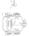
図1は実施の形態1に係るドアロックシステムの概略構成を説明する模式図である。実施の形態1に係るドアロックシステムは、車両100が備える複数のドア(以下、車両ドアともいう)を施錠又は解錠するためのシステムであり、車両100内に設けられたボディECU(Electronic Control Unit)110及び無線通信装置120、並びにユーザによって操作される携帯機200を備える。
Hereinafter, the present invention will be specifically described based on the drawings showing the embodiments thereof.
Embodiment 1
FIG. 1 is a schematic view illustrating a schematic configuration of a door lock system according to a first embodiment. The door lock system according to the first embodiment is a system for locking or unlocking a plurality of doors (hereinafter also referred to as a vehicle door) included in
ボディECU110は、無線通信装置120に接続されており、無線通信装置120を介して携帯機200と無線通信を行うと共に、車両ドアの施錠及び解錠に係る制御を行う機能を備える。
The body ECU 110 is connected to the
無線通信装置120は、携帯機200と無線通信を行うために、RF受信アンテナ123a及び複数のLF送信アンテナ124a〜124eを備える。RF受信アンテナ123aは、例えば無線通信装置120に内蔵されるアンテナであり、RF帯(RF : Radio Frequency)の周波数の信号を受信する。LF送信アンテナ124a〜124eは、例えば車両100が備える各ドアの周辺に設けられるアンテナであり、LF帯(LF : Low Frequency)の周波数の信号を送信する。本実施の形態では、LF送信アンテナ124a〜124eは、それぞれ、運転席側のドアの周辺、助手席側のドアの周辺、右後部座席側(運転席の後ろ側)のドアの周辺、左後部座席側(助手席の後ろ側)のドアの周辺、後部ドアの周辺に設けられているものとする。
The
携帯機200は、車両ドアの解錠及び施錠に係るユーザの操作を受付けるために、アンロックボタン203a及びロックボタン203bを備える。また、携帯機200は、車両側の無線通信装置120と無線通信を行うために、RF送信部204及びLF受信部205を備える(図3を参照)。携帯機200は、アンロックボタン203a又はロックボタン203bにより、車両ドアの解錠又は施錠に係るユーザの操作を受付けた場合、RF送信部204より車両ドアの解錠又は施錠を指示する信号を送信することが可能である。
The
ここで、LF帯の信号を用いた無線通信の通信範囲は1m程度であるのに対し、RF帯の信号を用いた無線通信の通信範囲は数十m程度である。このことを利用して、本実施の形態では、車両100が備える全てのドアを解錠する場合と、車両100が備える特定のドア(例えば運転席側のドア)を解錠する場合との切り替えを行う。具体的には、車両100のLF送信アンテナ124a〜124eによる通信範囲Ra〜Reの何れかに携帯機200が存在する場合に、車両ドアの解錠を指示する操作信号を携帯機200から受信したとき、ボディECU110は、車両100の全てのドアを解錠する制御を行う。また、LF送信アンテナ124a〜124eによる通信範囲Ra〜Reに携帯機200が存在しない場合に、車両ドアの解錠を指示する操作信号を携帯機200から受信した場合、ボディECU110は、特定のドアを解錠する制御を行う。
Here, while the communication range of the wireless communication using the signal of the LF band is about 1 m, the communication range of the wireless communication using the signal of the RF band is about several tens of meters. Using this, in the present embodiment, switching between the case of unlocking all the doors of the
図2はボディECU110及び無線通信装置120の内部構成を説明するブロック図である。ボディECU110は、制御部111、記憶部112、入出力部113、通信部114などを備える。
FIG. 2 is a block diagram for explaining the internal configuration of the
制御部111は、例えば、CPU(Central Processing Unit)、ROM(Read Only Memory)、RAM(Random Access Memory)などを備える。制御部111内のCPUは、ROMに格納された制御プログラムを実行することにより、ボディECU110が備える上記ハードウェアの動作を制御し、機器全体を本願に係る車両ドア解錠システムの車載制御装置として機能させる。制御部111内のRAMには、制御プログラムの実行中に生成される各種データが記憶される。なお、制御部111は、計測開始指示を与えてから計測終了指示を与えるまでの経過時間を計測するタイマ、数をカウントするカウンタ等の機能を備えていてもよい。
The control unit 111 includes, for example, a central processing unit (CPU), a read only memory (ROM), a random access memory (RAM), and the like. The CPU in the control unit 111 controls the operation of the hardware provided in the
記憶部112は、例えば、EEPROM(Electronically Erasable Programmable Read Only Memory)などの不揮発性メモリにより構成されており、ボディECU110を識別する識別情報等を記憶する。ここで、ボディECUの識別情報とは、例えば、ボディECU110を搭載する車両100のID(Identifier)番号、通信相手となる携帯機200のID番号、及び暗号処理に用いる鍵情報等である。
入出力部113は、ドアロック機構130及びドアロック操作部131を接続するためのインタフェースを備える。
The input /
ドアロック機構130は、車両100の各ドアの施錠又は解錠するための機械機構、及びこの機械機構を電気的に動作させるためのアクチュエータ等を有している。また、ドアロック操作部131は、例えば、車両100の運転席のドアに設けられたキーシリンダ、ドアハンドルに設けられたリクエストスイッチ等である。
The
例えば、車両100用のメカニカルキー(不図示)が車両100のドアに設けられたキーシリンダに挿入され、施錠操作又は解錠操作が行われた場合、ドアロック機構130は、アクチュエータ等を動作させ、ドアの施錠又は解錠を行う。このとき、メカニカルキーによりキーシリンダが操作された情報が入出力部113を通じてドアロック機構130に出力され、出力された情報に基づきドアロック機構130が動作するように構成されている。
For example, when a mechanical key (not shown) for the
また、携帯機200を持つユーザが、車両100のドアハンドルに設けられたリクエストスイッチを操作した場合、ボディECU110と携帯機200との間で無線通信を行う。その無線通信において、無線通信装置120がLF送信アンテナ124a〜124eから検出信号を送信し、検出信号に対する携帯機200からの応答信号を受信した場合、ボディECU110はドアの施錠又は解錠を行う。なお、リクエストスイッチは、押しボタン式のスイッチであってもよく、ドアハンドルへの接触を検知する接触センサを用いたスイッチであってもよい。
Further, when the user having
更に、ドアロック操作部131をユーザが操作することなく、ボディECU110と携帯機200との間の無線通信によりボディECU110がドアの施錠又は解錠を行えるように構成されている。具体的には、無線通信装置120のRF受信アンテナ123aにて携帯機200からの操作信号を受信した際、受信した操作信号に含まれる解錠又は施錠に係る情報に基づき、ボディECU110はドアの施錠又は解錠を行う。
Furthermore, the
通信部114は、例えばCAN通信インタフェースを備えており、通信線を介して無線通信装置120側の通信部125に接続されている。通信部114は、CANプロトコルに従って無線通信装置120とデータの送受信を行う。
The
無線通信装置120は、制御部121、記憶部122、RF受信部123、LF送信部124、通信部125などを備える。
The
制御部121は、例えば、CPU、ROM、RAMなどを備える。制御部121内のCPUは、ROM又は記憶部122に格納された制御プログラムを実行することにより、無線通信装置120が備える各ハードウェアの動作を制御する。
The
記憶部122は、EEPROMなどの不揮発性メモリにより構成されており、携帯機200との無線通信処理、ボディECU110とのCAN通信処理等を実行するための制御プログラムを記憶する。
The
RF受信部123は、RF受信アンテナ123aに接続されており、RF受信アンテナ123aを通じてRF帯の周波数を有する信号を受信する受信回路、受信した信号の受信信号強度(RSSI:Received Signal Strength Indicator)を測定する測定回路等を備える。本実施の形態では、RF受信部123は、携帯機200から送信される操作信号をRF受信アンテナ123aを通じて受信し、受信した操作信号を制御部121へ送出する。制御部121は、RF受信部123から受信した操作信号を、通信部125を通じてボディECU110へ送信する。
The
LF送信部124は、制御部121から出力される信号に基づきLF帯の周波数を有する信号を生成する信号生成回路、生成した信号を増幅する増幅回路等を備えており、増幅後の信号をLF送信アンテナ124a〜124eより外部へ送信する。本実施の形態では、LF送信部124は、制御部121からの指示により、携帯機200を検出するための検出信号をLF送信アンテナ124a〜124eを通じて送信する。ここで、LF送信部124が送信する検出信号には、記憶部112に記憶されているボディECU110の識別情報が含まれるものとする。
The
通信部125は、例えばCAN通信インタフェースを備えており、通信線を介してボディECU110側の通信部114に接続されている。通信部125は、CANプロトコルに従ってボディECU110とデータの送受信を行う。
The
図3は携帯機200の内部構成を説明するブロック図である。携帯機200は、制御部201、記憶部202、操作部203、RF送信部204、及びLF受信部205などを備える。
FIG. 3 is a block diagram for explaining the internal configuration of the
制御部201は、例えば、CPU、ROMなどを備える。制御部201内のCPUは、ROMに格納された制御プログラムを実行することにより、携帯機200が備える各ハードウェアの動作を制御し、機器全体を本願に係る車両ドア解錠システムにおける携帯機として機能させる。なお、制御部201は、計測開始指示を与えてから計測終了指示を与えるまでの経過時間を計測するタイマ、数をカウントするカウンタ等の機能を備えていてもよい。
The
記憶部202は、EEPROMなどの不揮発性メモリにより構成されており、携帯機200を識別するための識別情報を記憶する。ここで、携帯機200を識別する識別情報は、例えば、携帯機200のID番号、通信相手となるボディECU110を搭載する車両100のID番号、及び暗号処理に用いる鍵情報等である。
The
操作部203は、ユーザによる操作を受付けるためのインタフェースを備える。本実施の形態では、操作部203は、車両100のドアを解錠する際に操作されるアンロックボタン203a、及び車両100のドアを施錠する際に操作されるロックボタン203bを備える。操作部203は、アンロックボタン203a(又はロックボタン203b)がユーザにより操作された場合、アンロックボタン203a(又はロックボタン203b)が操作されたこと示す信号を制御部201へ出力する。制御部201は、アンロックボタン203a(又はロックボタン203b)が操作されたこと示す信号を受信した場合、車両100のドアの解錠(又は施錠)を指示する制御信号をRF送信部204へ送出する。
The
RF送信部204は、制御部201から出力される制御信号からRF帯の周波数を有する信号を生成する信号生成回路、生成した信号を増幅する増幅回路等を備えており、増幅後の信号をRF送信アンテナ204aより外部へ送信する。本実施の形態では、RF送信部204は、制御部201からの制御信号に応じて、車両ドアの解錠(又は施錠)を指示する操作信号をRF送信アンテナ204aより送信する。ここで、RF送信部204が送信する操作信号及び後述する応答信号には、記憶部202に記憶されている携帯機200の識別情報が含まれるものとする。
The
LF受信部205は、LF受信アンテナ205aに接続されており、LF受信アンテナ205aを通じてRF帯の周波数を有する信号を受信する受信回路、受信した信号の信号強度を測定する測定回路等を備える。本実施の形態では、LF受信部205は、車両100のLF送信アンテナ124a〜124eから送信される検出信号をLF受信アンテナ205aにて受信し、受信した検出信号を制御部201へ送出する。制御部201は、LF受信部205から検出信号を受信した場合、当該検出信号に対する応答信号をRF送信部204より送信する処理を行う。このとき、制御部201は、各LF送信アンテナ124a〜124eから送信される検出信号の信号強度(RSSI)の情報を付加した応答信号を、RF送信部204より送信する。
The
以下、本実施の形態に係るドアロックシステムの動作について説明する。
図4は携帯機200が実行する処理の手順を説明するフローチャートである。携帯機200の制御部201は、車両100のLF送信部124から送信される検出信号をLF受信部205にて受信したか否かを判断する(ステップS101)。受信していないと判断した場合(S101:NO)、制御部201は、後述するステップS105へ処理を移行する。
The operation of the door lock system according to the present embodiment will be described below.
FIG. 4 is a flowchart for explaining the procedure of processing executed by the
検出信号を受信したと判断した場合(S101:YES)、制御部201は、受信した検出信号に基づき認証処理を実行する(ステップS102)。車両100のLF送信部124から送信されてくる検出信号にはボディECU110を識別する識別情報が含まれるので、制御部201は、検出信号に含まれる識別情報と、記憶部202に記憶されている携帯機200の識別情報とを比較することにより、認証処理を実行することができる。
If it is determined that the detection signal has been received (S101: YES), the
次いで、制御部201は、ステップS102で実行した認証処理で認証に成功したか否かを判断する(ステップS103)。認証に成功していないと判断した場合(S103:NO)、制御部201は、後述するステップS105へ処理を移行する。
Next, the
認証に成功したと判断した場合(S103:YES)、制御部201は、検出信号に対する応答信号をRF送信部204より送信する(ステップS104)。このとき、制御部201は、各LF送信アンテナ124a〜124eから送信される検出信号の信号強度(RSSI)の情報を付加した応答信号を、RF送信部204より送信する。
If it is determined that the authentication is successful (S103: YES), the
次いで、制御部201は、ユーザによる操作(解錠操作又は施錠操作)を操作部203にて受付けたか否かを判断する(ステップS105)。アンロックボタン203a(又はロックボタン203b)が操作された場合(S105:YES)、操作部203は操作されたことを示す信号を制御部201へ送出する。よって、制御部201は、操作部203からの信号を受信することにより、ユーザによる操作(解錠操作又は施錠操作)を操作部203にて受付けたか否かを判断することができる。
Next, the
ユーザによる操作を受付けていないと判断した場合(S105:NO)、制御部201は、本フローチャートによる処理を終了する。一方、ユーザによる操作を受付けたと判断した場合、制御部201は、解錠操作又は施錠操作の何れであるかを示す情報、及び携帯機200の識別情報等を含む操作信号を、RF送信部204を通じて外部へ送信する(ステップS106)。
If it is determined that the user's operation has not been received (S105: NO), the
なお、図4のフローチャートでは、検出信号の受信判定を行った後に、ユーザによる操作の有無を判定する手順を説明したが、ユーザによる操作の有無を判定した後に、検出信号の受信判定を行ってもよいことは勿論のことである。 In the flowchart of FIG. 4, the procedure for determining the presence or absence of the operation by the user after performing the reception determination of the detection signal has been described, but after determining the presence or absence of the operation by the user, the reception determination of the detection signal is performed Of course it is also good.
本実施の形態に係るドアロックシステムでは、携帯機200を携帯するユーザが操作部203のアンロックボタン203aを操作したときに、車両100のLF送信アンテナ124a〜124eの通信範囲Ra〜Re内にユーザが存在するか否かに応じて、全てのドアを解錠するか、または特定のドアのみを解錠するかの制御を行う。このため、車両100に搭載されているボディECU110は、通信範囲Ra〜Reに存在する携帯機200の検出処理を行う。
In the door lock system according to the present embodiment, when the user carrying
図5はボディECU110が実行する携帯機200の検出処理の手順を説明するフローチャートである。ボディECU110は、車両100のドアが施錠されている場合に以下の処理を実行する。ボディECU110の制御部111は、通信部114を通じて無線通信装置120へ指示を与えることにより、LF送信アンテナ124a〜124eを通じて検出信号を外部へ送信させる(ステップS111)。制御部111は、検出信号を外部へ送信させた後、内蔵タイマを作動させることにより、無線通信装置120へ指示を与えてからの経過時間を計時する。
FIG. 5 is a flowchart for explaining the procedure of detection processing of the
次いで、ボディECU110の制御部111は、通信部114を通じて無線通信装置120と通信を行うことにより、携帯機200から送信される応答信号を無線通信装置120のRF受信部123にて受信したか否かを判断する(ステップS112)。
Next, the control unit 111 of the
携帯機200からの応答信号を受信していないと判断した場合(S112:NO)、制御部111は、内蔵タイマを参照して、所定時間が経過したか否かを判断する(ステップS113)。応答信号を受信することなく、所定時間が経過したと判断した場合(S113:YES)、制御部111は、処理をステップS111へ戻す。また、所定時間が経過していない場合(S113:NO)、制御部111は、処理をステップS112へ戻す。
If it is determined that the response signal from the
携帯機200からの応答信号を受信したと判断した場合(S112:YES)、制御部111は、受信した応答信号に基づき認証処理を実行する(ステップS114)。携帯機200から送信されてくる応答信号には携帯機200を識別する識別情報が含まれるので、制御部111は、応答信号に含まれる識別情報と、記憶部112に記憶されているボディECU110の識別情報とを比較することにより、認証処理を実行することができる。
If it is determined that the response signal from the
次いで、制御部111は、ステップS114で実行した認証処理で認証に成功したか否かを判断する(ステップS115)。認証に成功していないと判断した場合(S115:NO)、制御部111は、携帯機200を検出していないと判断し(ステップS116)、処理をステップS111へ戻す。
Next, the control unit 111 determines whether or not the authentication has succeeded in the authentication process performed in step S114 (step S115). If it is determined that the authentication is not successful (S115: NO), the control unit 111 determines that the
一方、認証に成功したと判断した場合(S115:YES)、制御部111は、携帯機200を検出したと判断し(ステップS117)、本フローチャートによる処理を終了する。なお、携帯機200を検出したと判断した場合、制御部111は、ステップS112で受信した応答信号に含まれるRSSIの情報に基づき、携帯機200が存在する存在領域を特定することも可能である。
On the other hand, when it is determined that the authentication is successful (S115: YES), the control unit 111 determines that the
図6はボディECU110が実行する解錠処理の手順を説明するフローチャートである。ボディECU110の制御部111は、通信部114を通じて無線通信装置120と通信を行うことにより、携帯機200から送信される操作信号を無線通信装置120のRF受信部123にて受信したか否かを判断する(ステップS121)。操作信号を受信していないと判断した場合(S121:NO)、制御部111は、操作信号を受信するまで待機する。
FIG. 6 is a flowchart for explaining the procedure of the unlocking process performed by the
操作信号を受信したと判断した場合(S121:YES)、制御部111は、受信した操作信号に基づき認証処理を実行する(ステップS122)。携帯機200から送信されてくる操作信号には携帯機200を識別する識別情報が含まれるので、制御部111は、操作信号に含まれる識別情報と、記憶部112に記憶されているボディECU110の識別情報とを比較することにより、認証処理を実行することができる。
If it is determined that the operation signal has been received (S121: YES), the control unit 111 executes an authentication process based on the received operation signal (step S122). Since the operation signal transmitted from the
次いで、制御部111は、ステップS122で実行した認証処理で認証に成功したか否かを判断する(ステップS123)。認証に成功していないと判断した場合(S123:NO)、処理をステップS121へ戻す。 Next, the control unit 111 determines whether or not the authentication has succeeded in the authentication process performed in step S122 (step S123). When it is determined that the authentication is not successful (S123: NO), the process is returned to step S121.
一方、認証に成功したと判断した場合(S123:YES)、制御部111は、携帯機200の検出処理を実行する(ステップS124)。制御部111は、図5のフローチャートに示される手順に従って携帯機200の検出処理を実行することができる。
On the other hand, when it is determined that the authentication is successful (S123: YES), the control unit 111 executes a detection process of the portable device 200 (step S124). The control unit 111 can execute the detection process of the
制御部111は、携帯機200の検出処理により携帯機200を検出したか否かを判断する(ステップS125)。携帯機200を検出したと判断した場合(S125:YES)、すなわち車両100の近傍にて携帯機200のアンロックボタン203aが操作されたと判断できる場合、制御部111は、車両100の全てのドアを解錠する制御信号を入出力部113よりドアロック機構130へ送出し、全てのドアを解錠する(ステップS126)。なお、携帯機200を携帯したユーザが車両100のドアハンドルに設けられたリクエストスイッチを操作した場合にも、制御部111は、車両100の全てのドアを解錠する制御信号を入出力部113よりドアロック機構130へ送出し、全てのドアを解錠するようにしてもよい。
The control unit 111 determines whether the
携帯機200を検出していないと判断した場合(S125:NO)、すなわち車両100から離隔した位置にて携帯機200のアンロックボタン203aが操作されたと判断できる場合、制御部111は、車両100の特定のドア(例えば運転席側のドア)を解錠する制御信号を入出力部113よりドアロック機構130へ送出し、特定のドアを解錠する(ステップS127)。なお、ステップS127で解錠する特定のドアの情報は記憶部112に予め記憶されているものとする。制御部111は、記憶部112に記憶されている解除すべきドアの情報に従って、特定のドアを解錠する制御信号をドアロック機構へ送出する。
When it is determined that the
なお、図6に示すフローチャートでは、携帯機200からの操作信号を受信した後に、携帯機200の検出処理を実行する構成としたが、携帯機200の検出処理の実行後に、携帯機200からの操作信号の有無を判断してもよい。
In the flowchart shown in FIG. 6, the detection process of the
以上のように、実施の形態1では、車両100の周囲を確認できる車両近傍からユーザが携帯機200のアンロックボタン203aを操作したと判断できる場合には、車両100の全てのドアを解錠するので、利便性を確保することができる。また、車両100から離隔した位置にてユーザが携帯機200のアンロックボタン203aを操作したと判断できる場合には、特定のドア(例えば運転席側のドア)を解錠するので、悪意を持った者が車両100内に侵入する可能性を低くすることができる。
As described above, in the first embodiment, when it can be determined that the user operates the
(実施の形態2)
実施の形態2では、車両100から離隔した位置にてユーザが携帯機200のアンロックボタン203aを操作したと判断できる場合に、ボディECU110の制御部111にて解錠すべきドアを決定する構成について説明する。
なお、ドアロックシステムの構成、ボディECU110、無線通信装置120、携帯機200の内部構成等は実施の形態1と同様であるため、その説明を省略することとする。
Second Embodiment
In the second embodiment, when it can be determined that the user has operated
The configuration of the door lock system, the
図7は実施の形態2における解錠処理の手順を説明するフローチャートである。ボディECU110の制御部111は、正当な携帯機200からの操作信号を受信し、かつ当該携帯機200を検出しなかった場合に、以下の処理を実行する。なお、正当な携帯機200からの操作信号を受信し、かつ当該携帯機200を検出した場合には、実施の形態1と同様に、制御部111は、車両100の全てのドアを解錠する制御を行う。
FIG. 7 is a flow chart for explaining the procedure of the unlocking process in the second embodiment. When the control unit 111 of the
制御部111は、内蔵タイマを用いて計時を開始する(ステップS201)。
次いで、制御部111は、図5のフローチャートに示される手順に従って、携帯機200の検出処理を実行する(ステップS202)。
The control unit 111 starts clocking using the built-in timer (step S201).
Next, the control unit 111 executes detection processing of the
制御部111は、検出処理によって携帯機200を検出したか否かを判断する(ステップS203)。携帯機200を検出しなかった場合(S203:NO)、制御部111は、計時を開始してから設定時間(例えば1分)が経過したか否かを判断する(ステップS204)。
The control unit 111 determines whether the
設定時間が経過していない場合(S204:NO)、制御部111は、処理をステップS202へ戻す。一方、携帯機200を検出することなく、設定時間が経過したと判断した場合(S204:YES)、ユーザによる携帯機200の誤操作の可能性があるため、制御部111は解錠処理を実行せずに、本フローチャートによる処理を終了する。
If the set time has not elapsed (S204: NO), the control unit 111 returns the process to step S202. On the other hand, when it is determined that the set time has elapsed without detecting the portable device 200 (S204: YES), there is a possibility that the user erroneously operates the
設定時間内に携帯機200を検出したと判断した場合(S203:YES)、車両100から離隔した位置にて携帯機200を操作したユーザが車両100に近づいてきたと判断できるので、制御部111は、検出結果に基づき、車両100に対するユーザの位置を特定する(ステップS205)。携帯機200の検出処理において、制御部111が受信する携帯機200からの応答信号にはRSSIの情報が含まれているので、制御部111は、このRSSIの情報に基づき、携帯機200を携帯しているユーザの位置を特定することができる。
If it is determined that the
制御部111は、ステップS205で特定したユーザの位置に応じて、解錠すべきドアを決定し、決定したドアを解錠する制御信号を入出力部113よりドアロック機構130へ送出することにより、決定したドアの解錠を行う(ステップS206)。例えば、ステップS205で特定したユーザの位置が、運転席側のドア付近に設けられたLF送信アンテナ124aの通信範囲Ra内である場合、制御部111は、運転席側のドアを解錠すると決定する。また、ステップS205で特定したユーザの位置が、助手席側のドア付近に設けられたLF送信アンテナ124bの通信範囲Rb内である場合、制御部111は、助手席側のドアを解錠すると決定する。特定したユーザの位置がLF送信アンテナ124c〜124eの通信範囲Rc〜Re内であると判断した場合についても同様であり、制御部111は、それぞれの場合において右後部座席側(運転席の後ろ側)のドア、左後部座席側(助手席の後ろ側)のドア、後部ドアを解錠すると決定する。
The control unit 111 determines a door to be unlocked according to the position of the user specified in step S205, and sends a control signal for unlocking the determined door from the input /
以上のように、実施の形態2では、正当なユーザが開けようとしている車両100のドアのみを解錠することができるので、このユーザの死角に不審者が潜んでいたとしても、不審者が潜んでいる付近のドアは施錠されたままの状態にすることができ、不審者が車両100内に侵入することを未然に防止することが可能となる。
As described above, in the second embodiment, only the door of the
今回開示された実施の形態は、全ての点で例示であって、制限的なものではないと考えられるべきである。本発明の範囲は、上述した意味ではなく、特許請求の範囲によって示され、特許請求の範囲と均等の意味及び範囲内での全ての変更が含まれることが意図される。 It should be understood that the embodiment disclosed herein is illustrative in all respects and not restrictive. The scope of the present invention is indicated not by the meaning described above but by the claims, and is intended to include all modifications within the meaning and scope equivalent to the claims.
例えば、本実施の形態では、5つのドアを有する車両100に適用したドアロックシステムについて説明したが、2つ以上のドアを有する車両に本実施の形態に係るドアロックシステムを適用できることは勿論のことである。
For example, although the door lock system applied to the
また、携帯機200は、車両ドアの施錠制御に係る制御信号を送信する専用の通信装置である必要はなく、ユーザが携帯するスマートフォン等の端末装置が本実施の形態に係る携帯機200の機能を備える構成であってもよい。
Further, the
100 車両
110 ボディECU
111 制御部
112 記憶部
113 入出力部
114 通信部
120 無線通信装置
121 制御部
122 記憶部
123 RF受信部
123a RF受信アンテナ
124 LF送信部
124a〜124e LF送信アンテナ
125 通信部
200 携帯機
201 制御部
202 記憶部
203 操作部
203a アンロックボタン
203b ロックボタン
204 RF送信部
204a RF送信アンテナ
205 LF受信部
205a LF受信アンテナ
100
111
Claims (7)
前記車載制御装置は、
前記携帯機を検出する検出部
を備え、
前記検出部が前記携帯機を検出することなく前記携帯機からの操作信号を受信した場合、前記車両が備える複数のドアのうちの特定のドアのみを解錠する
ことを特徴とする車両ドア解錠システム。 A portable device that includes an operation unit that receives an operation related to the unlocking of a plurality of doors provided in a vehicle, and transmits an operation signal when the operation is accepted by the operation unit, and an operation signal from the portable device A vehicle door unlocking system comprising: an on-vehicle control device that performs control related to the unlocking of the plurality of doors based on the received operation signal when received;
The on-board controller is
A detection unit for detecting the portable device;
When the detection unit receives an operation signal from the portable device without detecting the portable device, only a specific door of the plurality of doors provided in the vehicle is unlocked. Lock system.
前記検出部が前記携帯機を検出し、かつ、前記携帯機からの操作信号を受信した場合、前記車両が備える全てのドアを解錠する
ことを特徴とする請求項1に記載の車両ドア解錠システム。 The on-board controller is
The vehicle door solution according to claim 1, wherein when the detection unit detects the portable device and receives an operation signal from the portable device, all the doors provided in the vehicle are unlocked. Lock system.
前記携帯機を検出するための検出信号を送信する検出信号送信部と、
該検出信号送信部から送信した検出信号に対する応答信号を受信する応答信号受信部と
を備え、
前記携帯機は、
前記検出信号送信部から送信された検出信号を受信する検出信号受信部と、
該検出信号受信部にて受信した検出信号に対する応答信号を送信する応答信号送信部と
を備え、
前記検出部は、前記応答信号受信部にて受信した応答信号に基づき、前記携帯機を検出する
ことを特徴とする請求項1又は請求項2に記載の車両ドア解錠システム。 The vehicle is
A detection signal transmission unit that transmits a detection signal for detecting the portable device;
A response signal receiving unit for receiving a response signal to the detection signal transmitted from the detection signal transmission unit;
The portable device is
A detection signal reception unit that receives the detection signal transmitted from the detection signal transmission unit;
A response signal transmitting unit for transmitting a response signal to the detection signal received by the detection signal receiving unit;
The vehicle door unlocking system according to claim 1 or 2, wherein the detection unit detects the portable device based on a response signal received by the response signal reception unit.
前記応答信号送信部が送信する応答信号は、RF(Radio Frequency)帯の周波数による信号である
ことを特徴とする請求項3に記載の車両ドア解錠システム。 The detection signal transmitted by the detection signal transmission unit is a signal with a frequency of LF (Low Frequency) band,
The vehicle door unlocking system according to claim 3, wherein the response signal transmitted by the response signal transmission unit is a signal according to a frequency of an RF (Radio Frequency) band.
前記検出信号受信部にて受信した検出信号の信号強度を測定する測定部と、
前記応答信号送信部から送信する応答信号に前記測定部にて測定した信号強度の情報を付加する情報付加部と
を備え、
前記車載制御装置は、
前記検出部が前記携帯機を検出することなく前記携帯機からの操作信号を受信した場合、設定時間内に前記携帯機からの応答信号を受信したか否かを判断する判断部と、
前記設定時間内に前記携帯機からの応答信号を受信したと判断した場合、受信した応答信号に含まれる信号強度の情報に基づき、解錠すべきドアを決定する決定部と
を備えることを特徴とする請求項3又は請求項4に記載の車両ドア解錠システム。 The portable device is
A measurement unit that measures the signal strength of the detection signal received by the detection signal reception unit;
An information adding unit that adds information of the signal strength measured by the measuring unit to the response signal transmitted from the response signal transmitting unit;
The on-board controller is
A determination unit that determines whether a response signal from the portable device is received within a set time when the detection unit receives an operation signal from the portable device without detecting the portable device;
And a determination unit that determines a door to be unlocked based on information of signal strength included in the received response signal when it is determined that the response signal from the portable device is received within the set time. The vehicle door unlocking system according to claim 3 or 4.
前記携帯機を検出する検出部
を備え、
前記検出部が前記携帯機を検出することなく前記携帯機からの操作信号を受信した場合、前記車両が備える複数のドアのうちの特定のドアのみを解錠する
ことを特徴とする車載制御装置。 It is possible to communicate with a portable device that transmits an operation signal when receiving an operation relating to the unlocking of a plurality of doors provided in a vehicle, and when receiving an operation signal from the portable device, based on the received operation signal. An on-board control unit for controlling the unlocking of the plurality of doors;
A detection unit for detecting the portable device;
When the detection unit receives an operation signal from the portable device without detecting the portable device, only the specific door among the plurality of doors included in the vehicle is unlocked. .
Priority Applications (4)
| Application Number | Priority Date | Filing Date | Title |
|---|---|---|---|
| JP2016059193A JP6540570B2 (en) | 2016-03-23 | 2016-03-23 | Vehicle door unlocking system and in-vehicle control device |
| US16/080,224 US10471931B2 (en) | 2016-03-23 | 2017-03-21 | Vehicle door unlocking system and on-board control device |
| PCT/JP2017/011199 WO2017164165A1 (en) | 2016-03-23 | 2017-03-21 | Vehicle door unlocking system and onboard control device |
| CN201780012006.2A CN108699860A (en) | 2016-03-23 | 2017-03-21 | Car door system for unlocking and on-vehicle control apparatus |
Applications Claiming Priority (1)
| Application Number | Priority Date | Filing Date | Title |
|---|---|---|---|
| JP2016059193A JP6540570B2 (en) | 2016-03-23 | 2016-03-23 | Vehicle door unlocking system and in-vehicle control device |
Publications (2)
| Publication Number | Publication Date |
|---|---|
| JP2017172202A JP2017172202A (en) | 2017-09-28 |
| JP6540570B2 true JP6540570B2 (en) | 2019-07-10 |
Family
ID=59900407
Family Applications (1)
| Application Number | Title | Priority Date | Filing Date |
|---|---|---|---|
| JP2016059193A Expired - Fee Related JP6540570B2 (en) | 2016-03-23 | 2016-03-23 | Vehicle door unlocking system and in-vehicle control device |
Country Status (4)
| Country | Link |
|---|---|
| US (1) | US10471931B2 (en) |
| JP (1) | JP6540570B2 (en) |
| CN (1) | CN108699860A (en) |
| WO (1) | WO2017164165A1 (en) |
Families Citing this family (6)
| Publication number | Priority date | Publication date | Assignee | Title |
|---|---|---|---|---|
| DE112018004518T5 (en) * | 2017-10-19 | 2020-06-04 | Denso Corporation | POSITIONING SYSTEM FOR VEHICLES |
| JP2019161504A (en) * | 2018-03-14 | 2019-09-19 | パナソニックIpマネジメント株式会社 | Portable equipment |
| WO2019183163A1 (en) * | 2018-03-20 | 2019-09-26 | Antenum Llc | Orientation independent antennas with direction finding for remote keyless entry |
| US10636235B2 (en) * | 2018-03-26 | 2020-04-28 | Panasonic Intellectual Property Management Co., Ltd. | Vehicle wireless communication for performing communication between vehicle-mounted device and mobile device, identification information registration method |
| JP2019217924A (en) * | 2018-06-20 | 2019-12-26 | 本田技研工業株式会社 | Vehicle and control method |
| WO2020202945A1 (en) * | 2019-03-29 | 2020-10-08 | シャープ株式会社 | Storage device |
Family Cites Families (9)
| Publication number | Priority date | Publication date | Assignee | Title |
|---|---|---|---|---|
| JP3809934B2 (en) | 1999-08-09 | 2006-08-16 | 本田技研工業株式会社 | Vehicle remote control system |
| DE10361115A1 (en) | 2003-12-22 | 2005-07-21 | Daimlerchrysler Ag | Control method for remote control of motor vehicle doors/tailboards detects when a vehicle is approached and/or the position of an associated authenticating element |
| JP4595614B2 (en) * | 2005-03-25 | 2010-12-08 | 株式会社デンソー | Vehicle door control system |
| JP2008115653A (en) * | 2006-11-07 | 2008-05-22 | Mazda Motor Corp | Locking device for vehicular door |
| KR100957297B1 (en) * | 2008-04-28 | 2010-05-12 | 현대자동차주식회사 | A monitoring system of smart key |
| JP5974876B2 (en) * | 2012-12-07 | 2016-08-23 | 株式会社オートネットワーク技術研究所 | Vehicle lock control device |
| JP6183186B2 (en) * | 2013-11-29 | 2017-08-23 | 株式会社オートネットワーク技術研究所 | Door unlocking system |
| JP6359359B2 (en) * | 2014-07-02 | 2018-07-18 | アルプス電気株式会社 | Electronic key device |
| JP2017166167A (en) * | 2016-03-15 | 2017-09-21 | 本田技研工業株式会社 | Smart entry system |
-
2016
- 2016-03-23 JP JP2016059193A patent/JP6540570B2/en not_active Expired - Fee Related
-
2017
- 2017-03-21 US US16/080,224 patent/US10471931B2/en not_active Expired - Fee Related
- 2017-03-21 WO PCT/JP2017/011199 patent/WO2017164165A1/en active Application Filing
- 2017-03-21 CN CN201780012006.2A patent/CN108699860A/en active Pending
Also Published As
| Publication number | Publication date |
|---|---|
| JP2017172202A (en) | 2017-09-28 |
| WO2017164165A1 (en) | 2017-09-28 |
| CN108699860A (en) | 2018-10-23 |
| US20190016303A1 (en) | 2019-01-17 |
| US10471931B2 (en) | 2019-11-12 |
Similar Documents
| Publication | Publication Date | Title |
|---|---|---|
| JP6540570B2 (en) | Vehicle door unlocking system and in-vehicle control device | |
| US7928829B2 (en) | Method for controlling access to a vehicle | |
| JP5260430B2 (en) | Electronic key system | |
| JP5626627B2 (en) | Control system | |
| JP5173934B2 (en) | Electronic key system | |
| US20120268242A1 (en) | Vehicle security system and method of operation based on a nomadic device location | |
| EP3309755B1 (en) | Biometric-electronic key system | |
| JP5173935B2 (en) | Electronic key system | |
| JP6971156B2 (en) | Communications system | |
| JP2018534540A (en) | Method and apparatus for locating a portable radio unit | |
| JP5566414B2 (en) | Electronic key device | |
| JP5772038B2 (en) | Vehicle door lock system | |
| JP7125323B2 (en) | VEHICLE CONTROL DEVICE, VEHICLE CONTROL METHOD AND COMPUTER PROGRAM | |
| JP2010216079A (en) | Door lock control device and method and portable information processor | |
| JP7070080B2 (en) | Communication device | |
| WO2015104748A1 (en) | Auto lock system | |
| JP2020029715A (en) | Authentication system and authentication method | |
| WO2018047748A1 (en) | Vehicle-mounted communication system, vehicle-mounted device and portable apparatus | |
| WO2019116923A1 (en) | In-vehicle control device, in-vehicle control system, in-vehicle control method and computer program | |
| JP2020082856A (en) | On-vehicle control device, on-vehicle control method and computer program | |
| JP2021087033A (en) | System for vehicle, on-vehicle device, and terminal position identifying method | |
| JP2000145226A (en) | Keyless entry system | |
| WO2019116899A1 (en) | Vehicle communication system, portable device, and on-board device | |
| WO2018043108A1 (en) | Communication system and portable machine | |
| JP2023002854A (en) | electronic key system |
Legal Events
| Date | Code | Title | Description |
|---|---|---|---|
| A621 | Written request for application examination |
Free format text: JAPANESE INTERMEDIATE CODE: A621 Effective date: 20180628 |
|
| TRDD | Decision of grant or rejection written | ||
| A01 | Written decision to grant a patent or to grant a registration (utility model) |
Free format text: JAPANESE INTERMEDIATE CODE: A01 Effective date: 20190514 |
|
| A61 | First payment of annual fees (during grant procedure) |
Free format text: JAPANESE INTERMEDIATE CODE: A61 Effective date: 20190527 |
|
| R150 | Certificate of patent or registration of utility model |
Ref document number: 6540570 Country of ref document: JP Free format text: JAPANESE INTERMEDIATE CODE: R150 |
|
| LAPS | Cancellation because of no payment of annual fees |