JP6540552B2 - Fuel cell single cell - Google Patents
Fuel cell single cell Download PDFInfo
- Publication number
- JP6540552B2 JP6540552B2 JP2016041329A JP2016041329A JP6540552B2 JP 6540552 B2 JP6540552 B2 JP 6540552B2 JP 2016041329 A JP2016041329 A JP 2016041329A JP 2016041329 A JP2016041329 A JP 2016041329A JP 6540552 B2 JP6540552 B2 JP 6540552B2
- Authority
- JP
- Japan
- Prior art keywords
- anode
- fuel cell
- current collector
- cell
- current
- Prior art date
- Legal status (The legal status is an assumption and is not a legal conclusion. Google has not performed a legal analysis and makes no representation as to the accuracy of the status listed.)
- Active
Links
Images


Classifications
-
- Y—GENERAL TAGGING OF NEW TECHNOLOGICAL DEVELOPMENTS; GENERAL TAGGING OF CROSS-SECTIONAL TECHNOLOGIES SPANNING OVER SEVERAL SECTIONS OF THE IPC; TECHNICAL SUBJECTS COVERED BY FORMER USPC CROSS-REFERENCE ART COLLECTIONS [XRACs] AND DIGESTS
- Y02—TECHNOLOGIES OR APPLICATIONS FOR MITIGATION OR ADAPTATION AGAINST CLIMATE CHANGE
- Y02E—REDUCTION OF GREENHOUSE GAS [GHG] EMISSIONS, RELATED TO ENERGY GENERATION, TRANSMISSION OR DISTRIBUTION
- Y02E60/00—Enabling technologies; Technologies with a potential or indirect contribution to GHG emissions mitigation
- Y02E60/30—Hydrogen technology
- Y02E60/50—Fuel cells
Landscapes
- Inert Electrodes (AREA)
- Fuel Cell (AREA)
Description
本発明は、燃料電池単セルに関する。 The present invention relates to a single fuel cell.
従来、電解質として固体電解質を用いる固体電解質形の燃料電池単セルが知られている。 Conventionally, a solid electrolyte fuel cell single cell using a solid electrolyte as an electrolyte is known.
例えば、先行する特許文献1には、多孔質の板状金属基板と、金属基板の一方面から部分的に突出するように設置された集電部材と、集電部材を覆うように金属基板の一方面に配置されたアノードと、アノード上に配置された固体電解質層と、固体電解質層上に配置された空気極とを備え、集電部材が、アノードの層厚を超えて延びるように突出している燃料電池単セルが開示されている。
For example, in
しかしながら、従来の燃料電池単セルは、集電部材がアノードを貫くため、アノード内の反応点が減少し、出力向上が難しい。 However, in the case of the conventional single fuel cell, since the current collection member penetrates the anode, the reaction point in the anode decreases, and it is difficult to improve the output.
なお、アノードにおける気孔径を制御し、固体電解質層側からその反対側に向かって気孔径が大きくなるように気孔径を傾斜させることにより、反応機能と拡散機能とを分離し、反応点を確保する手法もある。しかし、このような構成のアノードを有する燃料電池単セルは、運転時間が長くなるにつれ、酸化還元反応によってアノード内で形態変化した導電性材料が気孔径の大きな層に吸収されやすい。その結果、アノード内の電子導電経路が途切れ、安定して長時間運転することが難しい。 The reaction function and the diffusion function are separated by securing the reaction point by controlling the pore diameter at the anode and tilting the pore diameter so that the pore diameter increases from the solid electrolyte layer side to the opposite side. There is also a method to However, in a single fuel cell having an anode of such a configuration, as the operation time increases, the conductive material whose shape is changed in the anode by the redox reaction is likely to be absorbed by the layer having a large pore diameter. As a result, the electron conduction path in the anode is interrupted, making it difficult to stably operate for a long time.
本発明は、かかる課題に鑑みてなされたものであり、高出力で安定して長時間運転可能な燃料電池単セルを提供しようとするものである。 The present invention has been made in view of the above problems, and an object of the present invention is to provide a single unit fuel cell that can be operated stably for a long time with high output.
本発明の一態様は、アノード(2)と、
該アノードの一方面から突出する少なくとも1つの集電部(3)と、
上記アノードの一方面側に配置されており、上記集電部が突出する上記アノードの一方面を覆う多孔質の支持体(4)と、
上記アノードの他方面側に配置された固体電解質層(5)と、
該固体電解質層における上記アノード側とは反対側に配置されたカソード(6)と、を有する燃料電池単セル(1)にある。
One aspect of the present invention is an anode (2),
At least one current collector (3) projecting from one side of the anode;
A porous support (4) disposed on one side of the anode and covering one side of the anode from which the current collector protrudes;
A solid electrolyte layer (5) disposed on the other side of the anode;
And a cathode (6) disposed on the opposite side to the anode side in the solid electrolyte layer.
上記燃料電池単セルでは、集電部が、アノードの一方面から突出している。そして、集電部が突出するアノードの一方面が、支持体により覆われている。上記燃料電池単セルは、アノードの外部に集電部が形成されているので、アノード内の反応場を減少させずに済む。そのため、上記燃料電池単セルは、アノード内に反応場を十分確保することができる。それ故、上記燃料電池単セルは、反応場にて発電された電気を集電部を介して低損失で取り出すことができ、出力向上を図ることが可能となる。また、上記燃料電池単セルでは、アノードの一方面に形成された集電部がアノードの電子導電経路として機能する。そのため、上記燃料電池単セルは、アノード側における電子導電経路の途切れを抑制することができ、安定して長時間運転することが可能となる。 In the unit cell, the current collector protrudes from one side of the anode. And one side of the anode from which a current collection part protrudes is covered by the support body. In the unit cell of the fuel cell, since the current collector is formed outside the anode, it is not necessary to reduce the reaction site in the anode. Therefore, the single fuel cell can secure a sufficient reaction site in the anode. Therefore, the fuel cell single cell can extract the electricity generated at the reaction site with low loss through the current collector, and can improve the output. Further, in the unit cell of the fuel cell, the current collector formed on one side of the anode functions as an electron conduction path of the anode. Therefore, the unit cell of the fuel cell can suppress interruption of the electron conduction path on the anode side, and can stably operate for a long time.
なお、特許請求の範囲及び課題を解決する手段に記載した括弧内の符号は、後述する実施形態に記載の具体的手段との対応関係を示すものであり、本発明の技術的範囲を限定するものではない。 The reference numerals in parentheses described in the claims and the means for solving the problems indicate the correspondence with the specific means described in the embodiments described later, and the technical scope of the present invention is limited. It is not a thing.
(実施形態1)
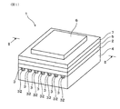
実施形態1の燃料電池単セルについて、図1〜図7を用いて説明する。図1〜図7に例示されるように、本実施形態の燃料電池単セル1は、アノード2と、集電部3と、支持体4と、固体電解質層5と、カソード6とを有している。なお、固体電解質層3の固体電解質として固体酸化物セラミックスを用いる燃料電池は、固体酸化物形燃料電池(SOFC)と称される。燃料電池単セル1は、平板形の電池構造を有することができる。各図では、燃料電池単セル1の外形が四角形状である例が示されている。
(Embodiment 1)
The single fuel cell of
アノード2は、通常、多孔質であり、図3、図5に例示されるように、気孔21を含んでいる。アノード2は、具体的には、導電性材料と固体電解質材料とを含む構成とすることができる。この場合、導電性材料は、アノード2内で電子導電経路を構成する材料となる。一方、固体電解質材料は、アノード2内でイオン導電経路を構成する骨格材料となる。アノード2に用いられる導電性材料としては、例えば、Ni、Ni合金などを例示することができる。アノード2に用いられる固体電解質材料としては、例えば、イットリア安定化ジルコニア(YSZ)、スカンジア安定化ジルコニア(ScSZ)等の酸化ジルコニウム系酸化物などを例示することができる。本実施形態では、アノード2の材料として、具体的には、Niとイットリア安定化ジルコニアとの混合物を用いることができる。
The
アノード2の厚みは、反応持続性、取り扱い性、加工性等の観点から、好ましくは10μm以上、より好ましくは15μm以上とすることができる。アノード2の厚みは、電極反応抵抗の低減等の観点から、好ましくは30μm以下、より好ましくは25μm以下とすることができる。
The thickness of the
集電部3は、アノード2の一方面から突出している。アノード2は、例えば、平坦な層状に構成することができ、集電部3は、具体的には、層状のアノード2における支持体4側の一方面から突出している。集電部3の表面の一部は、アノード2の一方面に接続している。
The
集電部3は、少なくとも1つあればよい。各図では、燃料電池単セル1が、複数の集電部3を有している例が示されている。各集電部3は、例えば、アノード2の一方面に沿ってそれぞれ直線状に延びる構成とすることができ、互いに離間した状態で配置することができる。この構成によれば、各集電部3により、アノード2の面内方向で均一に集電しやすい燃料電池単セル1が得られる。なお、各図では、セル端面にてアノード2側の電気を取り出すことができるように、直線状に延びる各集電部3の少なくとも一方の端部がセル端面に露出している例が示されている。
At least one
集電部3は、具体的には、導電性材料を含む構成とすることができる。集電部3に用いられる導電性材料としては、例えば、Ni、Ni合金などを例示することができる。本実施形態では、集電部3の導電性材料として、具体的には、Niを用いることができる。
Specifically, the
集電部3およびアノード2がいずれも導電性材料を含んでいる場合、集電部3とアノード2との界面23に存在する導電性材料の割合は、アノード2内部に存在する導電性材料の割合よりも大きい構成とすることができる。この構成によれば、集電部3による電子導電経路が確実なものとなり、アノード2側における電子導電経路の途切れを抑制しやすく、安定して長時間運転可能な燃料電池単セル1を得やすくなる。なお、上記各割合の大小関係は、次のようにして把握することができる。図6に例示されるように、走査型電子顕微鏡を用い、集電部3とアノード2との界面23における領域A、アノード2の内部における領域Bを断面観察(×1000倍)し、それぞれ、任意の50μmの幅をEDX測定により線分析する。得られた線分析のパターンを比較することにより、上記各割合の大小関係を求めることができる。
When both the
集電部3に含まれる導電性材料の線熱膨張係数とアノード2に含まれる導電性材料の線熱膨張係数との差は、具体的には、1×10⁻⁶/K以下とすることができる。この場合には、長期運転時に熱による膨張、収縮によって集電部3がアノード2から剥離し難く、安定して長期運転可能な燃料電池単セル1を得やすくなる。
Specifically, the difference between the linear thermal expansion coefficient of the conductive material contained in the
上記線熱膨張係数の差は、集電部3とアノード2との密着性等の観点から、好ましくは0.9×10⁻⁶/K以下、より好ましくは0.8×10−6/K以下、さらに好ましくは0.7×10−6/K以下、さらにより好ましくは0.6×10−6/K以下、さらにより一層好ましくは0.5×10−6/K以下とすることができる。なお、上記線熱膨張係数の差は、基本的には、JIS R1618:2002 「ファインセラミックスの熱機械分析による熱膨張の測定方法」に準拠して測定される。具体的には、集電部3に含まれる導電性材料と同じ材料による試料、アノード2に含まれる導電性材料と同じ材料による試料を準備する。各試料をそれぞれ全膨張式熱機械分析装置にセットし、温度を10℃/分の昇温速度で上げていく。温度TがT0(=100℃)からT1(=700℃)に上がるまでに、各試料は長さL0からL1まで膨張する。この際の各線熱膨張係数(/K)を、(dL/dT)T=T1/L0の計算式よりそれぞれ算出する。但し、(dL/dT)T=T1は、温度TがT1のときにおける長さ曲線の傾きである。上記線熱膨張係数の差は、得られた各試料の線熱膨張係数の差の絶対値より算出される。
The difference in linear thermal expansion coefficient is preferably 0.9 × 10 −6 / K or less, more preferably 0.8 × 10 −6 / K, from the viewpoint of the adhesion between the
集電部3は、具体的には、アノード2の一方面に沿って連続的に繋がった連続部位を含む構成とすることができる。この構成によれば、アノード2の一方面に沿って電気を取り出しやすい燃料電池単セル1が得られる。なお、集電部3は、安定して長時間運転することが可能な範囲内で、一部に不連続部位が含まれていてもよい。不連続部位では、隣接する連続部位同士がアノード2内の導電性材料を介して電気的に接続されるため、電子導電経路の途切れは生じないからである。
Specifically, the
連続部位の形態は、例えば、各図に示されるように、アノード2の一方面に沿って複数の半球状部が繋がった構成とすることができる。このような複数の半球状部が繋がった連続部位は、燃料電池単セル1を長時間運転することにより、集電部3を形成する材料が形態変化を繰り返し、安定な半球状の形状となろうとする現象を利用して形成することができる。
The form of the continuous portion can be, for example, a configuration in which a plurality of hemispherical portions are connected along one surface of the
集電部3に含まれる連続部位の長さの割合は、具体的には、アノード2の一方面に平行なアノード2内の任意の平面における導電性材料の繋がり長さの割合よりも大きい構成とすることができる。この構成は、燃料電池単セル1を断面観察し、観察長さに対する上記連続部位の長さの割合と、観察長さに対する上記導電性材料の繋がり長さの割合とを比較することにより確認することができる。
Specifically, the ratio of the length of the continuous portion included in
集電部3の突出量は、電気伝導度等の観点から、好ましくは1μm以上、より好ましくは3μm以上、さらに好ましくは5μm以上とすることができる。集電部3の突出量は、セル強度等の観点から、好ましくは30μm以下、より好ましくは20μm以下、さらに好ましくは10μm以下とすることができる。なお、集電部3の突出量は、走査型電子顕微鏡を用い、集電部3とアノード2との界面23を断面観察(×1000倍)し、任意の10か所の集電部3の突出長さを測定した際の各測定値の平均値である。
The amount of protrusion of the
集電部3の幅は、集電性向上、形成容易性等の観点から、好ましくは20μm以上、より好ましくは50μm以上、さらに好ましくは100μm以上とすることができる。集電部3の幅は、セル強度等の観点から、好ましくは1000μm以下、より好ましくは500μm以下、さらに好ましくは200μm以下とすることができる。また、集電部3のピッチは、セル強度、形成容易性等の観点から、好ましくは50μm以上、より好ましくは100μm以上、さらに好ましくは400μm以上とすることができる。集電部3のピッチは、集電性向上等の観点から、好ましくは5000μm以下、より好ましくは2000μm以下、さらに好ましくは1000μm以下とすることができる。
The width of the
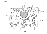
集電部3におけるアノード2に接続する面30を除いた表面31は、空隙32により覆われている構成とすることができる。この構成によれば、アノード2の一方面に配置された集電部3に沿って空隙32が存在することになる。そのため、空隙32を、アノード2に供給される燃料ガスを面内方向に拡散させる際の拡散流路として機能させることができる。また、空隙32を、発電反応によってアノード2で生じた水蒸気を排出するための排出流路として機能させることもできる。さらに、集電部3が空隙32により覆われていることで、支持体4に含まれる大きな気孔に集電部3が接し難くなる。そのため、酸化還元反応による集電部3の変化は生じるが、集電部3の導電性材料が支持体4に移動することを防ぐことができ、電気伝導性を安定させることができる。なお、空隙32は、例えば、次のように形成することができる。集電部3に用いられる導電性材料の酸化物より集電部形成材を形成する。この際、集電部形成材は、集電部3の容積と空隙32の容積とを合わせた容積を有する。形成した集電部形成材を還元雰囲気で還元することにより導電性材料の酸化物を導電性材料とし、この際に生じる体積収縮により、集電部3を覆う空隙32を形成することができる。
The
空隙32は、集電部3と支持体4との間に存在している。各図に例示されるように、空隙32には、アノード2の一部が露出していてもよい。また、空隙32における支持体4側の壁面には、集電部3を形成する材料の一部33が付着していてもよい。
An
支持体4は、アノード2の一方面側に配置されおり、集電部3が突出するアノード2の一方面を覆っている。支持体4は、多孔質であり、図3、図5に例示されるように、気孔41を含んでいる。但し、アノード2に供給される燃料ガスを拡散させるなどの観点から、支持体4の気孔率は、アノード2の気孔率よりも十分に大きくされている。つまり、アノード2は、支持体4よりも緻密質に形成されている。
The
支持体4の材料としては、例えば、ジルコニア、マグネシア、アルミナなどを例示することができる。ジルコニアとしては、例えば、イットリア安定化ジルコニア、スカンジア安定化ジルコニア等の酸化ジルコニウム系酸化物などを例示することができる。この場合には、セルの他材料との熱膨張差を小さくしやすく、反りの少ない燃料電池単セルを得やすくなる。本実施形態では、支持体4の材料として、具体的には、イットリア安定化ジルコニアを用いることができる。なお、支持体4は、導電性を有している必要がないため、導電性材料を含んでいなくてもよいが、導電性材料を含むこともできる。
Examples of the material of the
支持体4の厚みは、セル強度の確保等の観点から、好ましくは100μm以上、より好ましくは200μm以上、より好ましくは300μm以上とすることができる。支持体4の厚みは、ガス拡散性の向上等の観点から、好ましくは800μm以下、より好ましくは700μm以下とすることができる。
The thickness of the
固体電解質層5は、アノード2の他方面側に配置されている。
The
固体電解質層5の材料としては、強度、熱的安定性に優れる等の観点から、イットリア安定化ジルコニア、スカンジア安定化ジルコニア等の酸化ジルコニウム系酸化物を好適に用いることができる。固体電解質層5の材料としては、イオン伝導度、機械的安定性、他の材料との両立、空気雰囲気から燃料ガス雰囲気まで化学的に安定である等の観点から、イットリア安定化ジルコニアが好適である。本実施形態では、固体電解質層3の材料として、具体的には、イットリア安定化ジルコニアを用いることができる。
As a material of the
固体電解質層5の厚みは、オーミック抵抗の低減などの観点から、好ましくは3〜20μm、より好ましくは4〜15μm、さらに好ましくは5〜10μmとすることができる。
The thickness of the
カソード6は、固体電解質層5におけるアノード2側とは反対側に配置されている。本実施形態では、カソード6の外形が、アノード2の外形よりも小さく形成されている。なお、各図では、支持体4、アノード2、固体電解質層5および中間層7(後述)の外形は、いずれも同じ大きさとされている。
The
カソード6の材料としては、遷移金属ペロブスカイト型酸化物などを例示することができる。遷移金属ペロブスカイト型酸化物としては、具体的には、例えば、LaxSr1−xCoO3系酸化物、LaxSr1−xCoyFe1−yO3系酸化物、SmxSr1−xCoO3系酸化物(但し、上記において、0≦x≦1、0≦y≦1)などを例示することができる。これらは1種または2種以上併用することができる。本実施形態では、カソード6の材料として、具体的には、LaxSr1−xCoyFe1−yO3系酸化物(0≦x≦1、0≦y≦1)を用いることができる。
Examples of the material of the
カソード6の厚みは、ガス拡散性、電極反応抵抗、集電性などの観点から、好ましくは20〜100μm、より好ましくは30〜80μmとすることができる。
The thickness of the
燃料電池単セル1は、各図に例示されるように、固体電解質層5とカソード6との間にさらに中間層7を有することができる。中間層7は、主に、固体電解質層材料とカソード材料との反応を抑制するための層である。
The fuel
中間層7の材料としては、例えば、CeO2、または、CeO2にGd、Sm、Y、La、Nd、Yb、Ca、および、Hoから選択される1種または2種以上の元素等がドープされたセリア系固溶体等の酸化セリウム系酸化物などを例示することができる。これらは1種または2種以上併用することができる。本実施形態では、中間層7の材料として、具体的には、CeO2にGdがドープされたセリア系固溶体を用いることができる。
As a material of the
また、中間層7の厚みは、オーミック抵抗の低減、カソードからの元素拡散の抑制等の観点から、好ましくは1〜20μm、より好ましくは2〜5μmとすることができる。
The thickness of the
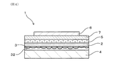
本実施形態では、燃料電池単セル1は、上述した支持体4、アノード2、固体電解質層5、中間層7、および、カソード6がこの順に積層され、互いに接合されている。
In the present embodiment, in the fuel cell
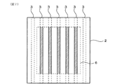
燃料電池単セル1において、セルの発電有効面積に対する集電部3の有効面積率は、3%以上30%以下の範囲内とすることができる。この場合には、集電部3によるアノード2側の集電効率が良好であり、支持体4とアノード2との接合性が高く、支持体4とアノード2との剥離を抑制しやすい燃料電池単セル1が得られる。集電部3の有効面積率は、集電効率の向上などの観点から、好ましくは3%以上、より好ましくは5%以上、さらに好ましくは7%以上、さらにより好ましくは10%以上とすることができる。集電部3の有効面積率は、支持体4とアノード2との接合部位を十分に確保する、空隙32の確保容易性などの観点から、好ましくは25%以下、より好ましくは20%以下、さらに好ましくは18%以下、さらにより好ましくは15%以下とすることができる。
In the
集電部3の有効面積率について、図7を用いて説明する。図7には、燃料電池単セル1をカソード6側から見た場合におけるカソード6、アノード2、集電部6のそれぞれの位置関係が示されている。セルの発電有効面積とは、アノード2/固体電解質層5/カソード6の3層が揃って積層されている部分の面積をいう。本実施形態では、アノード2と固体電解質層5とは同じ面積であり、カソード6の面積は、アノード2の面積よりも小さい。したがって、本実施形態では、セルの発電有効面積は、図7で示されるカソード6の面積と一致している。一方、集電部3の有効面積は、セルの発電有効面積内で、集電部3が形成されている部分の面積をいう。本実施形態では、カソード6の面積内に配置された各集電部3の合計面積(図7におけるハッチング部分)が、集電部3の有効面積となる。集電部3の有効面積率(%)は、100×集電部3の有効面積/セルの発電有効面積の式より算出することができる。
The effective area ratio of the
燃料電池単セル1では、集電部3が、アノード2の一方面から突出している。そして、集電部3が突出するアノード2の一方面が、支持体4により覆われている。燃料電池単セル1は、アノード2の外部に集電部3が形成されているので、アノード2内の反応場を減少させずに済む。そのため、燃料電池単セル1は、アノード2内に反応場を十分確保することができる。それ故、燃料電池単セル1は、反応場にて発電された電気を集電部3を介して低損失で取り出すことができ、出力向上を図ることが可能となる。また、燃料電池単セル1では、アノード2の一方面に形成された集電部3がアノード2の電子導電経路として機能する。そのため、燃料電池単セル1は、アノード2側における電子導電経路の途切れを抑制することができ、安定して長時間運転することが可能となる。
In the
(実施形態2)
実施形態2の燃料電池単セルについて、図8および図9を用いて説明する。なお、実施形態2以降において用いられる符号のうち、既出の実施形態において用いた符号と同一のものは、特に示さない限り、既出の実施形態におけるものと同様の構成要素等を表す。
Second Embodiment
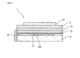
A single fuel cell of
図8および図9に例示されるように、本実施形態の燃料電池単セル1は、少なくとも1つのセル端面に、各集電部3と導通する端面電極8を有している。その他の構成は、実施形態1と同様である。
As illustrated in FIG. 8 and FIG. 9, the fuel cell
燃料電池単セル1は、少なくとも1つのセル端面に端面電極8を有しているので、各集電部3で集電された電気を端面電極8よりまとめて取り出すことができる。それ故、燃料電池単セル1によれば、セル端面での電気の取り出し性に優れる。また、燃料電池単セル1は、集電部3で集電された電気を端面電極8を介して外部へ接続することができるので、燃料電池単セル1を複数有する燃料電池セルスタックにおける電気的な接続構造を簡易化するのに有利である。
Since the fuel
本実施形態では、具体的には、燃料電池単セル1の外形が四角形状とされている。そのため、セル端面が6面ある。各図では、6つのセル端面のうちの一つに、端面電極8が形成されている例が示されている。端面電極8が形成されるセル端面には、各集電部3の端部が露出しており、各集電部3の端部が端面電極8に電気的に接続されている。これにより、各集電部3から端面電極8に確実に電気を受け取り可能とされている。
Specifically, in the present embodiment, the outer shape of the fuel
端面電極8の材料としては、集電部3を形成する材料よりも酸化し難い材料を用いることが好ましい。この場合には、端面電極8の酸化還元に対する形態安定性が向上し、集電部3で集電された電気を確実に外部へ取り出すことができる。そのため、接続信頼性に優れた燃料電池単セル1が得られる。また、長時間運転時に端面電極8が酸化し難いので、長期運転の信頼性を高めることができる。また、支持体4に導電性材料が不要となるので、支持体4の材料選択の余地が広がる。そのため、支持体4の強度向上によるセル強度の向上、支持体4に導電性材料を用いないことによるコスト低減等の利点を有する燃料電池単セル1が得られる。その他の作用効果は、実施形態1と同様である。
As a material of the
集電部3を形成する材料よりも酸化し難い端面電極8の材料は、エリンガムダイアグラム等を参考に選定することができる。端面電極8の材料として、具体的には、例えば、W、Mo、Cu、Au、Ag、Pt族、これらの合金などを例示することができる。
The material of the
なお、端面電極8は、セル端面における支持体4にのみ接するように設けられていてもよいし、支持体4、アノード2に接するように設けられていてもよい。また、端面電極8の一部は、支持体4の気孔41にその一部が存在していてもよい。この場合には、端面電極8のセル端面への接合性を向上させることができる。端面電極8の一部は、アノード2の気孔21、隙間32にもその一部が存在していてもよい。
The
(実験例)
以下、実験例を用いてより具体的に説明する。
<試料1の燃料電池単セル>
−材料準備−
8YSZ粉末(平均粒子径:0.5μm)と、カーボン(造孔剤)と、ポリビニルブチラールと、酢酸イソアミルおよび1−ブタノールとをボールミルにて混合することによりスラリーを調製した。ドクターブレード法を用いて、樹脂シート上に上記スラリーを層状に塗工し、乾燥させた後、樹脂シートを剥離することにより、支持体形成用シートを準備した。支持体形成用シートの厚みは、110μmとした。なお、上記平均粒子径は、レーザー回折・散乱法により測定した体積基準の累積度数分布が50%を示すときの粒子径(直径)d50である(以下、同様)。
(Experimental example)
Hereinafter, it demonstrates more concretely using an experimental example.
<Fuel cell single cell of
-Material preparation-
A slurry was prepared by mixing 8YSZ powder (average particle size: 0.5 μm), carbon (pore forming agent), polyvinyl butyral, isoamyl acetate and 1-butanol in a ball mill. The above-described slurry was applied in a layer form on a resin sheet using a doctor blade method, dried, and then the resin sheet was peeled off to prepare a support-forming sheet. The thickness of the support forming sheet was 110 μm. The above average particle diameter is the particle diameter (diameter) d50 when the volume-based cumulative frequency distribution measured by the laser diffraction / scattering method indicates 50% (the same applies hereinafter).
NiO粉末(平均粒子径:0.6μm)と、8YSZ粉末(平均粒子径:0.2μm)と、カーボン(造孔剤)と、ポリビニルブチラールと、酢酸イソアミルおよび1−ブタノールとをボールミルにて混合することによりスラリーを調製した。NiO粉末と8YSZ粉末の質量比は、65:35である。ドクターブレード法を用いて、樹脂シート上に上記スラリーを層状に塗工し、乾燥させることにより、樹脂シート付のアノード形成用シートを準備した。アノード形成用シートの厚みは、30μmとした。なお、アノード形成用シートにおけるカーボン量は、支持体形成用シートと比較して少量とされている。 NiO powder (average particle size: 0.6 μm), 8YSZ powder (average particle size: 0.2 μm), carbon (pore-forming agent), polyvinyl butyral, isoamyl acetate and 1-butanol mixed in a ball mill The slurry was prepared by The mass ratio of NiO powder to 8YSZ powder is 65:35. The above-described slurry was applied in a layer form on a resin sheet using a doctor blade method, and dried to prepare an anode forming sheet with a resin sheet. The thickness of the anode forming sheet was 30 μm. The amount of carbon in the sheet for forming an anode is small compared to the sheet for forming a support.
NiO粉末(平均粒子径:0.6μm)、エチルセルロース(バインダー)、ジヒドロターピネオールアセテート(溶剤)、分散剤、レベリング剤、沈降防止剤をプラネタリーミキサーにて撹拌した後、三本ロールにて混練することにより、集電部形成用ペーストを調製した。樹脂シート上のアノード形成用シートの表面に、スクリーン印刷法を用いて、集電部形成用ペーストをパターン印刷した。ここでの印刷パターンは、等間隔で並ぶ71本の線状ペーストより構成される線状パターンであり、複数の直線状の集電部を形成するためのものである。各線状ペーストの線幅は100μm、線間ピッチは1000μm、線厚みは80μmとした。各線状ペーストを乾燥させた後、樹脂シートを剥離することにより、その一方面に集電部形成用ペーストによる線状パターンが印刷された集電部形成用ペースト付きアノード形成用シートを準備した。 After stirring NiO powder (average particle size: 0.6 μm), ethylcellulose (binder), dihydroterpineol acetate (solvent), dispersant, leveling agent, anti-settling agent with a planetary mixer, it is kneaded with a triple roll. Thus, a current collector forming paste was prepared. The paste for current collection part formation was pattern-printed on the surface of the sheet | seat for anode formation on a resin sheet using the screen-printing method. The printing pattern here is a linear pattern composed of 71 linear pastes arranged at equal intervals, and is for forming a plurality of linear current collectors. The line width of each linear paste was 100 μm, the line pitch was 1000 μm, and the line thickness was 80 μm. After drying each linear paste, the resin sheet was peeled off to prepare an anode forming sheet with a current collector forming paste on which a linear pattern of the current collector forming paste is printed on one side thereof.
8YSZ粉末(平均粒子径:0.2μm)と、ポリビニルブチラールと、酢酸イソアミルおよび1−ブタノールとをボールミルにて混合することによりスラリーを調製した。ドクターブレード法を用いて、樹脂シート上に上記スラリーを層状に塗工し、乾燥させた後、樹脂シートを剥離することにより、固体電解質層形成用シートを準備した。固体電解質層形成用シートの厚みは、5.0μmとした。 A slurry was prepared by mixing 8YSZ powder (average particle size: 0.2 μm), polyvinyl butyral, isoamyl acetate and 1-butanol in a ball mill. The above-mentioned slurry was applied in a layer form on a resin sheet using a doctor blade method, dried, and then the resin sheet was peeled off to prepare a sheet for forming a solid electrolyte layer. The thickness of the solid electrolyte layer-forming sheet was 5.0 μm.
10mol%のGdがドープされたCeO2(10GDC)粉末(平均粒子径:0.3μm)と、ポリビニルブチラールと、酢酸イソアミル、2−ブタノールおよびエタノールとをボールミルにて混合することによりスラリーを調製した。ドクターブレード法を用いて、樹脂シート上に上記スラリーを層状に塗工し、乾燥させた後、樹脂シートを剥離することにより、中間層形成用シートを準備した。中間層形成用シートの厚みは、4.0μmとした。 A slurry was prepared by mixing 10 mol% Gd-doped CeO 2 (10 GDC) powder (average particle size: 0.3 μm), polyvinyl butyral, isoamyl acetate, 2-butanol and ethanol in a ball mill . The above-mentioned slurry was applied in a layer form on a resin sheet using a doctor blade method, dried, and then the resin sheet was peeled off to prepare a sheet for intermediate layer formation. The thickness of the intermediate layer forming sheet was 4.0 μm.
LSC(La0.6Sr0.4CoO3)粉末(平均粒子径:2.0μm)と、エチルセルロースと、テルピネオールとを3本ロールにて混練することにより、カソード形成用ペーストを準備した。 A paste for forming a cathode was prepared by kneading LSC (La 0.6 Sr 0.4 CoO 3 ) powder (average particle size: 2.0 μm), ethyl cellulose and terpineol with a triple roll.
Cu粉末(平均粒子径:0.5μm)、アクリル系樹脂(バインダー)、ジヒドロターピネオールアセテート(溶剤)、分散剤、レベリング剤、沈降防止剤をプラネタリーミキサーにて撹拌した後、三本ロールにて混練し、さらにジヒドロターピネオールアセテート(溶剤)を加え、プラネタリーミキサーにて撹拌することにより、端面電極形成用ペーストを準備した。 Cu powder (average particle size: 0.5 μm), acrylic resin (binder), dihydroterpineol acetate (solvent), dispersant, leveling agent, anti-settling agent after being stirred by a planetary mixer After kneading, dihydroterpineol acetate (solvent) was added, and the mixture was stirred by a planetary mixer to prepare a paste for end face electrode formation.
支持体形成用シート、集電部形成用ペースト付きアノード形成用シート、固体電解質層形成用シート、および、中間層形成用シートをこの順に積層し、圧着した。なお、集電部形成用ペースト付きアノード形成用シートにおける線状パターンの印刷面は、支持体形成用シート側に配置されている。また、圧着には、CIP成形法を用いた。この際、CIP成形条件は、温度80℃、加圧力50MPa、加圧時間10分という条件とした。得られた圧着体を四角形状に打ち抜き、積層体を得た。得られた積層体は脱脂した。なお、積層体の4つの端面のうち、対向する2つの端面には、集電部形成用ペーストが露出している。 A sheet for forming a support, a sheet for forming an anode with a paste for forming a current collection portion, a sheet for forming a solid electrolyte layer, and a sheet for forming an intermediate layer were laminated in this order and pressure-bonded. In addition, the printing surface of the linear pattern in the sheet for anode formation with paste for current collection part formation is arrange | positioned at the sheet | seat side for support body formation. Moreover, the CIP molding method was used for pressure bonding. At this time, CIP molding conditions were a temperature of 80 ° C., a pressure of 50 MPa, and a pressure time of 10 minutes. The obtained crimped body was punched into a square shape to obtain a laminate. The resulting laminate was degreased. In addition, the paste for current collection part formation is exposed to two opposing end surfaces among four end surfaces of a laminated body.
上記積層体を、大気雰囲気中、1350℃で2時間焼成した。これにより、支持体(200μm)、アノード(20μm)、固体電解質層(3μm)、および、中間層(3μm)がこの順に積層された焼結体を得た。得られた焼結体におけるアノードの支持体側の面には、上記線状パターンに対応して、NiOより構成される緻密な集電部形成材が複数突出していた。また、当該複数の集電部形成材は、上記圧着により、支持体内に食い込んだ状態で形成された。また、焼結体の4つの端面のうち、対向する2つの端面には、集電部形成材が露出していた。なお、この時点では、支持体内に埋設された集電部形成材と支持体との間に隙間は形成されていなかった。 The laminate was fired at 1350 ° C. for 2 hours in the air. Thus, a sintered body in which a support (200 μm), an anode (20 μm), a solid electrolyte layer (3 μm), and an intermediate layer (3 μm) were laminated in this order was obtained. On the surface of the anode on the support side in the obtained sintered body, a plurality of dense current collector formation members made of NiO were protruded corresponding to the linear pattern. Moreover, the said several current collection part formation material was formed in the state which bited in into the support body by the said crimping | compression-bonding. Moreover, the current collection part formation material was exposed to two opposing end surfaces among four end surfaces of a sintered compact. At this point, no gap was formed between the current collector forming material embedded in the support and the support.
上記焼結体における中間層の表面に、カソード形成用ペーストをスクリーン印刷法により塗布し、大気雰囲気中、950℃で2時間焼成(焼付)することによって層状のカソード(50μm)を形成した。なお、カソードの外形は、アノードの外形よりも小さく形成した。これにより、平板形のセルを得た。 A cathode-forming paste was applied by screen printing to the surface of the intermediate layer in the above-mentioned sintered body, and baked (baked) in an air atmosphere at 950 ° C. for 2 hours to form a layered cathode (50 μm). In addition, the external shape of the cathode was formed smaller than the external shape of the anode. Thus, a flat cell was obtained.
得られたセルにおける集電部形成材が露出するセル端面の一つに、ディップコート法を用いて、端面電極形成用ペーストを塗布した。この際、固体電解質層、中間層およびカソードは、端面電極形成用ペーストが塗布されないようにマスクした。これにより、上記セル端面のうち、支持体の端面およびアノードの端面に、端面電極形成用ペーストを塗布した。なお、端面電極形成用ペーストは、支持体の端面から支持体の気孔内に含浸していた。 The end face electrode forming paste was applied to one of the cell end faces where the current collector forming material in the obtained cell is exposed, using a dip coating method. At this time, the solid electrolyte layer, the intermediate layer and the cathode were masked so as not to apply the end face electrode forming paste. Thus, the end face electrode forming paste was applied to the end face of the support and the end face of the anode among the cell end faces. The end face electrode forming paste was impregnated into the pores of the support from the end face of the support.
端面電極形成用ペーストが塗布された支持体およびアノードが還元雰囲気に曝られるとともに、固体電解質層、中間層およびカソードが還元雰囲気に曝されないように構成した。そして、端面電極形成用ペーストが塗布された支持体およびアノードを、水素ガスによる還元雰囲気中、800℃、12時間の条件で還元処理した。これにより、集電部形成材に含まれていたNiOを還元し、Niより構成される集電部を形成した。また、アノードに含まれていたNiOを還元し、Niとした。また、端面電極形成用ペーストに含まれていたCuは、アノード内に形成されたNiと結合して導電パスを形成するとともに端面電極を形成した。これにより、試料1の燃料電池単セルを得た。
The support on which the end face electrode forming paste was applied and the anode were exposed to a reducing atmosphere, and the solid electrolyte layer, the intermediate layer and the cathode were not exposed to the reducing atmosphere. Then, the support and the anode to which the paste for forming the end face electrode was applied were subjected to reduction treatment under conditions of 800 ° C. for 12 hours in a reducing atmosphere with hydrogen gas. Thereby, NiO contained in the current collection part formation material was reduced, and the current collection part comprised from Ni was formed. In addition, NiO contained in the anode was reduced to Ni. Further, Cu contained in the end face electrode forming paste was combined with Ni formed in the anode to form a conductive path and to form an end face electrode. Thus, a single fuel cell of
試料1の燃料電池単セルでは、集電部におけるアノードに接続する面を除いた表面は、NiOが40%程度体積収縮したことによって形成された空隙によって覆われていた。また、試料1の燃料電池単セルでは、集電部の一方端部は、端面電極に接続されていた。また、試料1の燃料電池単セルにおける、セルの発電有効面積に対する集電部の有効面積率は、10%であった。
In the unit cell of the fuel cell of
試料1の燃料電池単セルの作製において、アノード形成用シートの表面に集電部形成用ペーストをパターン印刷する際の条件を種々変更することにより、試料2の燃料電池単セル、試料3の燃料電池単セル、試料4の燃料電池単セルを得た。セルの発電有効面積に対する集電部の有効面積率は、試料2の燃料電池単セルで20%、試料3の燃料電池単セルで25%、試料4の燃料電池単セルで30%であった。集電部の有効面積率が30%を超えると、支持体とアノードとの接合面が減少する傾向が見られた。そのため、集電部の有効面積率を30%以下とすることにより、支持体4とアノード2との剥離抑制に有利な燃料電池単セル1を得やすくなることが確認された。また、集電部の有効面積率が大きくなるにつれ、集電部を覆う空隙が少なくなる傾向が見られた。そのため、集電部を覆う空隙を十分に確保する観点から、集電部の有効面積率は20%以下とすることが望ましいことが確認された。
The fuel cell single cell of
なお、試料1〜4の燃料電池単セルの作製では、アノード形成用シートの表面に集電部形成用ペーストがパターン印刷されている。そのため、各燃料電池単セルにおいて、集電部とアノードとの界面に存在する導電性材料(Ni)の割合がアノード内部に存在する導電性材料(Ni)の割合よりも大きいことは、上述したEDX測定によって線分析を行うまでもなく明らかであるといえる。 In addition, in preparation of the fuel cell single cell of the samples 1-4, the paste for current collection part formation is pattern-printed on the surface of the sheet | seat for anode formation. Therefore, in each single fuel cell, the ratio of the conductive material (Ni) present at the interface between the current collector and the anode is greater than the ratio of the conductive material (Ni) present inside the anode, as described above. It can be said that EDX measurement is clear without performing line analysis.
本発明は、上記各実施形態、実験例に限定されるものではなく、その要旨を逸脱しない範囲において種々の変更が可能である。また、各実施形態に示される各構成は、各実施形態内、各実施形態間で任意に組み合わせることができる。 The present invention is not limited to the above embodiments and experimental examples, and various modifications can be made without departing from the scope of the invention. In addition, each configuration shown in each embodiment can be arbitrarily combined with each other in each embodiment.
1 燃料電池単セル
2 アノード
3 集電部
4 支持体
5 固体電解質層
6 カソード
1 Fuel Cell
Claims (7)
該アノードの一方面から突出する少なくとも1つの集電部(3)と、
上記アノードの一方面側に配置されており、上記集電部が突出する上記アノードの一方面を覆う多孔質の支持体(4)と、
上記アノードの他方面側に配置された固体電解質層(5)と、
該固体電解質層における上記アノード側とは反対側に配置されたカソード(6)と、を有する燃料電池単セル(1)。 An anode (2),
At least one current collector (3) projecting from one side of the anode;
A porous support (4) disposed on one side of the anode and covering one side of the anode from which the current collector protrudes;
A solid electrolyte layer (5) disposed on the other side of the anode;
And a cathode (6) disposed on the side of the solid electrolyte layer opposite to the anode side.
上記集電部と上記アノードとの界面(23)に存在する導電性材料の割合は、上記アノード内部に存在する導電性材料の割合よりも大きい、請求項1または2に記載の燃料電池単セル。 Both the current collector and the anode contain a conductive material,
The fuel cell single cell according to claim 1 or 2, wherein the ratio of the conductive material present at the interface (23) between the current collector and the anode is larger than the ratio of the conductive material present inside the anode. .
Priority Applications (1)
| Application Number | Priority Date | Filing Date | Title |
|---|---|---|---|
| JP2016041329A JP6540552B2 (en) | 2016-03-03 | 2016-03-03 | Fuel cell single cell |
Applications Claiming Priority (1)
| Application Number | Priority Date | Filing Date | Title |
|---|---|---|---|
| JP2016041329A JP6540552B2 (en) | 2016-03-03 | 2016-03-03 | Fuel cell single cell |
Publications (2)
| Publication Number | Publication Date |
|---|---|
| JP2017157476A JP2017157476A (en) | 2017-09-07 |
| JP6540552B2 true JP6540552B2 (en) | 2019-07-10 |
Family
ID=59810774
Family Applications (1)
| Application Number | Title | Priority Date | Filing Date |
|---|---|---|---|
| JP2016041329A Active JP6540552B2 (en) | 2016-03-03 | 2016-03-03 | Fuel cell single cell |
Country Status (1)
| Country | Link |
|---|---|
| JP (1) | JP6540552B2 (en) |
Families Citing this family (7)
| Publication number | Priority date | Publication date | Assignee | Title |
|---|---|---|---|---|
| JP6972963B2 (en) * | 2017-11-24 | 2021-11-24 | 株式会社デンソー | Anode for solid oxide fuel cell and single cell for solid oxide fuel cell |
| WO2019239641A1 (en) | 2018-06-12 | 2019-12-19 | 日本碍子株式会社 | Electrochemical cell |
| JP6761497B2 (en) * | 2019-02-22 | 2020-09-23 | 日本碍子株式会社 | Cell stack and electrochemical cell |
| KR102915149B1 (en) * | 2022-10-31 | 2026-01-20 | 단국대학교 산학협력단 | Anode support substrate and manufacturing method thereof |
| WO2025104824A1 (en) * | 2023-11-14 | 2025-05-22 | 日本碍子株式会社 | Electrochemical cell |
| WO2025104825A1 (en) * | 2023-11-14 | 2025-05-22 | 日本碍子株式会社 | Electrochemical cell |
| WO2025104826A1 (en) * | 2023-11-14 | 2025-05-22 | 日本碍子株式会社 | Electrochemical cell |
Family Cites Families (5)
| Publication number | Priority date | Publication date | Assignee | Title |
|---|---|---|---|---|
| US8278013B2 (en) * | 2007-05-10 | 2012-10-02 | Alan Devoe | Fuel cell device and system |
| US20110053053A1 (en) * | 2007-09-20 | 2011-03-03 | Stmicroelectronics S.A. | Cell holder for fuel cell |
| JP5489057B2 (en) * | 2009-07-03 | 2014-05-14 | 日産自動車株式会社 | Solid oxide fuel cell |
| JP2011076959A (en) * | 2009-09-30 | 2011-04-14 | Dainippon Printing Co Ltd | Single cell of solid oxide fuel cell, and solid oxide fuel cell including the same |
| JP5613808B1 (en) * | 2013-09-24 | 2014-10-29 | 日本碍子株式会社 | Fuel cell |
-
2016
- 2016-03-03 JP JP2016041329A patent/JP6540552B2/en active Active
Also Published As
| Publication number | Publication date |
|---|---|
| JP2017157476A (en) | 2017-09-07 |
Similar Documents
| Publication | Publication Date | Title |
|---|---|---|
| JP6540552B2 (en) | Fuel cell single cell | |
| JP5080951B2 (en) | Horizontal stripe fuel cell stack and fuel cell | |
| JP5523472B2 (en) | FUEL CELL, CELL STACK, FUEL CELL MODULE, AND FUEL CELL DEVICE | |
| JP5171159B2 (en) | Fuel cell and fuel cell stack, and fuel cell | |
| JP5791552B2 (en) | FUEL CELL AND METHOD FOR PRODUCING LAMINATED SINTERED BODY | |
| JP5804894B2 (en) | Fuel cell | |
| WO2014208730A1 (en) | Cell, cell stacker, module, and module storage device | |
| JP2012074307A (en) | Power generation cell for solid oxide fuel cell | |
| JP2011119178A (en) | Solid oxide fuel cell | |
| JPWO2011093328A1 (en) | FUEL CELL CELL, FUEL CELL CELL DEVICE, FUEL CELL MODULE, AND FUEL CELL DEVICE | |
| JP5281950B2 (en) | Horizontally-striped fuel cell stack, manufacturing method thereof, and fuel cell | |
| JP5294649B2 (en) | Cell stack and fuel cell module | |
| JP2012074306A (en) | Power generation cell for solid oxide fuel cell | |
| JP7089838B2 (en) | Single cell for solid oxide fuel cell and its manufacturing method, and cathode for solid oxide fuel cell and its manufacturing method | |
| JP5489673B2 (en) | FUEL CELL CELL, CELL STACK DEVICE EQUIPPED WITH THE SAME, FUEL CELL MODULE, AND FUEL CELL DEVICE | |
| JP2009087539A (en) | Fuel cell and fuel cell stack, and fuel cell | |
| JP6972963B2 (en) | Anode for solid oxide fuel cell and single cell for solid oxide fuel cell | |
| WO2011138915A1 (en) | High-temperature structural material, structural body for solid electrolyte fuel cell, and solid electrolyte fuel cell | |
| JP4901996B2 (en) | Fuel cell | |
| KR102111859B1 (en) | Solid oxide fuel cell and a battery module comprising the same | |
| JP5132879B2 (en) | Horizontal stripe fuel cell and fuel cell | |
| JP6088949B2 (en) | Fuel cell single cell and manufacturing method thereof | |
| JP6654765B2 (en) | Solid oxide fuel cell stack | |
| JP5072188B2 (en) | Current collector film and flat plate solid oxide fuel cell using the same | |
| JP2015002035A (en) | Method for manufacturing solid oxide fuel battery cell |
Legal Events
| Date | Code | Title | Description |
|---|---|---|---|
| A621 | Written request for application examination |
Free format text: JAPANESE INTERMEDIATE CODE: A621 Effective date: 20180604 |
|
| A977 | Report on retrieval |
Free format text: JAPANESE INTERMEDIATE CODE: A971007 Effective date: 20190424 |
|
| TRDD | Decision of grant or rejection written | ||
| A01 | Written decision to grant a patent or to grant a registration (utility model) |
Free format text: JAPANESE INTERMEDIATE CODE: A01 Effective date: 20190514 |
|
| A61 | First payment of annual fees (during grant procedure) |
Free format text: JAPANESE INTERMEDIATE CODE: A61 Effective date: 20190527 |
|
| R151 | Written notification of patent or utility model registration |
Ref document number: 6540552 Country of ref document: JP Free format text: JAPANESE INTERMEDIATE CODE: R151 |
|
| R250 | Receipt of annual fees |
Free format text: JAPANESE INTERMEDIATE CODE: R250 |
|
| R250 | Receipt of annual fees |
Free format text: JAPANESE INTERMEDIATE CODE: R250 |
|
| R250 | Receipt of annual fees |
Free format text: JAPANESE INTERMEDIATE CODE: R250 |
|
| R250 | Receipt of annual fees |
Free format text: JAPANESE INTERMEDIATE CODE: R250 |