JP6540271B2 - Information decryption apparatus, information decryption method and program - Google Patents
Information decryption apparatus, information decryption method and program Download PDFInfo
- Publication number
- JP6540271B2 JP6540271B2 JP2015127038A JP2015127038A JP6540271B2 JP 6540271 B2 JP6540271 B2 JP 6540271B2 JP 2015127038 A JP2015127038 A JP 2015127038A JP 2015127038 A JP2015127038 A JP 2015127038A JP 6540271 B2 JP6540271 B2 JP 6540271B2
- Authority
- JP
- Japan
- Prior art keywords
- information
- output
- decoding
- unit
- decoded
- Prior art date
- Legal status (The legal status is an assumption and is not a legal conclusion. Google has not performed a legal analysis and makes no representation as to the accuracy of the status listed.)
- Active
Links
Images


Classifications
-
- H—ELECTRICITY
- H04—ELECTRIC COMMUNICATION TECHNIQUE
- H04B—TRANSMISSION
- H04B10/00—Transmission systems employing electromagnetic waves other than radio-waves, e.g. infrared, visible or ultraviolet light, or employing corpuscular radiation, e.g. quantum communication
- H04B10/11—Arrangements specific to free-space transmission, i.e. transmission through air or vacuum
- H04B10/114—Indoor or close-range type systems
- H04B10/116—Visible light communication
-
- H—ELECTRICITY
- H04—ELECTRIC COMMUNICATION TECHNIQUE
- H04B—TRANSMISSION
- H04B10/00—Transmission systems employing electromagnetic waves other than radio-waves, e.g. infrared, visible or ultraviolet light, or employing corpuscular radiation, e.g. quantum communication
- H04B10/07—Arrangements for monitoring or testing transmission systems; Arrangements for fault measurement of transmission systems
-
- H—ELECTRICITY
- H04—ELECTRIC COMMUNICATION TECHNIQUE
- H04B—TRANSMISSION
- H04B10/00—Transmission systems employing electromagnetic waves other than radio-waves, e.g. infrared, visible or ultraviolet light, or employing corpuscular radiation, e.g. quantum communication
- H04B10/60—Receivers
- H04B10/66—Non-coherent receivers, e.g. using direct detection
- H04B10/67—Optical arrangements in the receiver
Landscapes
- Physics & Mathematics (AREA)
- Electromagnetism (AREA)
- Engineering & Computer Science (AREA)
- Computer Networks & Wireless Communication (AREA)
- Signal Processing (AREA)
- Optical Communication System (AREA)
- Studio Devices (AREA)
Description
本発明は、情報復号装置、情報復号方法及びプログラムに関する。 The present invention relates to an information decoding apparatus, an information decoding method, and a program.
従来より、可視光通信を用いた情報伝送において、送信装置が関連づけられた複数のマーカーを発光し、受信装置が複数のマーカーを撮像し、発光の態様に基づいて情報を取得する技術がある(例えば特許文献1参照)。 2. Description of the Related Art Conventionally, in information transmission using visible light communication, there is a technology in which a transmitting device emits a plurality of markers associated with each other, a receiving device captures a plurality of markers, and information is acquired based on the light emission mode ( See, for example, Patent Document 1).
しかしながら、上述した従来の技術では、送信側がマーカーの数や配置を変更した場合、その変更を受信側が把握していないと、関連する全てのマーカーが撮像されず、結果的に完全な情報を取得できない可能性があった。 However, in the above-described conventional technique, when the transmitting side changes the number or arrangement of markers, if the receiving side does not know the change, all related markers are not imaged, and as a result, complete information is acquired There was a possibility that it could not be done.
本願発明はこのような問題点に鑑みてなされたものであり、複数のマーカーを用いた可視光通信システムにおいて、任意の変更があっても、情報受信側での情報の把握を容易にすることを目的とする。 The present invention has been made in view of such problems, and in a visible light communication system using a plurality of markers, it is easy to grasp information on the information receiving side even if there is any change. With the goal.
上記目的を達成するため、本発明に係る情報復号装置は、可視光通信用の複数のマーカーが発する光を夫々受光する受光手段と、前記受光手段により夫々受光された光に基づいて、前記複数のマーカーが発した情報へ夫々復号する復号手段と、前記復号手段によって復号された情報を出力する出力手段と、前記復号手段によって復号された複数の情報に、所定の情報が含まれているか否かを判断する判断手段と、前記判断手段により前記所定の情報が含まれていないと判断された場合に前記復号手段によって夫々復号された情報を出力するよう前記出力手段を制御する第1の出力制御手段と、前記判断手段により前記所定の情報が含まれていると判断された場合に夫々復号された前記情報を統合した情報を出力するよう前記出力手段を制御する第2の出力制御手段と、を備えることを特徴とする。 In order to achieve the above object, an information decoding apparatus according to the present invention comprises a plurality of light receiving means for respectively receiving light emitted by a plurality of markers for visible light communication, and the plurality of light receiving means based on light received by the light receiving means. Whether the predetermined information is included in the decoding means for respectively decoding the information generated by the marker, the output means for outputting the information decoded by the decoding means, and the plurality of pieces of information decoded by the decoding means First output means for controlling the output means to output information decoded respectively by the decoding means when the judgment means for judging whether the predetermined information is not included by the judgment means and the judgment means The output means is controlled to output information obtained by combining the decoded information when it is determined by the control means and the determination means that the predetermined information is included. Characterized in that it comprises a second output control means.
上記目的を達成するため、本発明に係る情報復号方法は、可視光通信用の複数のマーカーが発する光を夫々受光させる受光ステップと、前記受光ステップにて夫々受光された光に基づいて、前記複数のマーカーが発した情報へ夫々復号する復号ステップと、前記復号ステップにて復号された複数の情報に、所定の情報が含まれているか否かを判断する判断ステップと、前記判断ステップにて前記所定の情報が含まれていないと判断された場合に前記復号ステップにて夫々復号された情報を出力するよう出力部を制御する第1の出力制御ステップと、前記判断ステップにて前記所定の情報が含まれていると判断された場合に夫々復号された前記情報を統合した情報を出力するよう前記出力部を制御する第2の出力制御ステップと、を含むことを特徴とする。 In order to achieve the above object, according to the information decoding method of the present invention, the light receiving step for respectively receiving the light emitted by the plurality of markers for visible light communication and the light received in the light receiving step are different. A decoding step of respectively decoding information generated by a plurality of markers; a determination step of determining whether predetermined information is included in the plurality of information decoded in the decoding step; A first output control step of controlling an output unit to output information decoded respectively in the decoding step when it is judged that the predetermined information is not included, and the predetermined step in the judgment step a second output control step of controlling the output unit to output the information that integrates the information respectively decoded if the information is determined is included, to include And butterflies.
上記目的を達成するため、本発明に係るプログラムは、受光部と情報出力部とを備える装置が有するコンピュータを、前記受光部に対し、可視光通信用の複数のマーカーが発する光を夫々受光させる受光手段、前記受光手段により夫々受光された光に基づいて、前記複数のマーカーが発した情報へ夫々復号する復号手段、前記復号手段によって復号された情報を前記情報出力部にて出力させる出力手段、前記復号手段によって復号された複数の情報に、所定の情報が含まれているか否かを判断する判断手段、前記判断手段により前記所定の情報が含まれていないと判断された場合に前記復号手段によって夫々復号された情報を出力するよう前記出力手段を制御する第1の出力制御手段、前記判断手段により前記所定の情報が含まれていると判断された場合に夫々復号された前記情報を統合した情報を出力するよう前記出力手段を制御する第2の出力制御手段、として機能させることを特徴とする。 To achieve the above object, a program according to the present invention causes a computer included in a device including a light receiving unit and an information output unit to receive light emitted by a plurality of markers for visible light communication with respect to the light receiving unit . A light receiving means, a decoding means for respectively decoding information emitted by the plurality of markers based on light received by the light receiving means, and an output means for outputting the information decoded by the decoding means at the information output unit Determining means for determining whether or not predetermined information is included in the plurality of pieces of information decoded by the decoding means; and when the determination means determines that the predetermined information is not included. First output control means for controlling the output means to output information decoded respectively by the means, and determining that the predetermined information is contained by the determination means Characterized in that to function respectively decoded the information second output control means for controlling said output means to output the integrated information as, if it is.
本発明によれば、複数のマーカーを用いた可視光通信システムにおいて、任意の変更があっても、情報受信側での情報の把握を容易にすることができる。 According to the present invention, in a visible light communication system using a plurality of markers, even if there is any change, it is possible to easily grasp information on the information receiving side.
以下、図面を参照して、本発明の実施形態に係る可視光通信システムを説明する。 Hereinafter, a visible light communication system according to an embodiment of the present invention will be described with reference to the drawings.
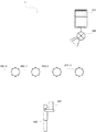
図1は、可視光通信システムの構成を示す図である。図1に示すように、可視光通信システム1は、サーバ100と、マーカー200−0〜200−3(以下、マーカー200−0〜200−3のそれぞれを限定しない場合には、適宜「マーカー200」と称する)と、撮像装置としての携帯機器300と、を含んで構成される。サーバ100とマーカー200とにより可視光通信制御システムが構成される。
FIG. 1 is a diagram showing the configuration of a visible light communication system. As shown in FIG. 1, in the case where the visible
サーバ100は、通信ネットワーク500を介してマーカー200との間で通信を行い、マーカー200を制御する。マーカー200は、サーバ100の制御に従って、各種の情報に対応して変調された光を発する。本実施形態では、マーカー200−0〜200−3は、図1に示すように、直線上に左から順にマーカー200−0、マーカー200−1、マーカー200−2、マーカー200−3の順に配置される。携帯機器300は、タブレット型パーソナルコンピュータ、携帯電話機、スマートフォン、ノート型パーソナルコンピュータ等の持ち運びが可能な電子機器である。携帯機器300はユーザ400によって所持される。携帯機器300は、マーカー200が配置されている領域を撮像するとともに、マーカー200が発した光を受け、その発光態様に基づいた情報を取得して表示する。
The
図2は、サーバ100の構成を示す図である。図2に示すように、サーバ100は、制御部102、メモリ104、操作部106、表示部107及び有線通信部108を含む。
FIG. 2 is a diagram showing the configuration of the
制御部102は、例えばCPU(Central Processing Unit)によって構成される。制御部102は、メモリ104に記憶されたプログラム(例えば、後述する図5に示すサーバ100の動作を実現するためのプログラム)に従ってソフトウェア処理を実行することにより、サーバ100が具備する各種機能を制御するために、マーカー制御部112を有する。マーカー制御部112は、マーカー200が発する光の輝度や色相(発光色)を制御する。
The
メモリ104は、例えばRAM(Random Access Memory)やROM(Read Only Memory)である。メモリ104は、サーバ100における制御等に用いられる各種情報(プログラム等)を記憶する。有線通信部108は、例えばLAN(Local Area Network)カードである。有線通信部108は、通信ネットワーク500を介してマーカー200との間で通信を行う。
The
操作部106は、テンキーやファンクションキー等によって構成され、ユーザの操作内容を入力するために用いられるインタフェースである。表示部107は、例えば、LCD(Liquid Crystal Display)、PDP(Plasma Display Panel)、EL(Electroluminescence)ディスプレイ等によって構成される。表示部107は、制御部102から出力された画像信号に従って画像を表示する。
The
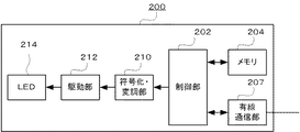
図3は、マーカー200の構成を示す図である。図3に示すように、マーカー200は、制御部202、メモリ204、有線通信部207、符号化・変調部210、駆動部212及びLED(Light Emitting Diode)214を含む。
FIG. 3 is a diagram showing the configuration of the
制御部202は、例えばCPUによって構成される。制御部202は、メモリ204に記憶されたプログラムに従ってソフトウェア処理を実行することにより、マーカー200が具備する各種機能を制御する。メモリ204は、例えばRAMやROMである。メモリ204は、マーカー200における制御等に用いられる各種情報(プログラム等)を記憶する。有線通信部207は、例えばLANカードである。有線通信部207は、通信ネットワーク500を介してサーバ100との間で通信を行う。
The
符号化・変調部210は、制御部202から出力されたデータをビットデータ列に符号化する。更に、符号化・変調部210は、ビットデータ列に基づくデジタル変調を行う。駆動部212は、符号化・変調部210から出力される信号に対応し、LED214が発する光の輝度や色相を時間的に変化させるための駆動信号を生成する。LED214は、駆動部212から出力される駆動信号に応じて、時間的に輝度や色相(発光色)が変化する光を発する。
The encoding /
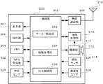
図4は、携帯機器300の構成を示す図である。図4に示す携帯機器300は、制御部302、メモリ304、操作部306、表示部307、無線通信部308、アンテナ310、レンズ312、撮像部314、画像処理部316、GPS(Global Positioning System)受信機322、方位センサ324、傾斜センサ326及び加速度センサ328を含む。
FIG. 4 is a diagram showing the configuration of the
制御部302は、例えばCPUによって構成される。制御部302は、メモリ304に記憶されたプログラム(例えば、後述する図7に示す携帯機器300の動作を実現するためのプログラム)に従ってソフトウェア処理を実行し、携帯機器300が具備する各種機能を実現するために、マーカー検出部332、情報取得部336及び出力制御部338を有する。
The
マーカー検出部332は、後述する画像処理部316からのフレーム内のマーカー200を検出する。情報取得部336は、マーカー200の発光態様に基づいた情報を取得する。出力制御部338は、フレーム内のマーカー200の位置に、そのマーカー200の発光態様に基づいた情報を表示する制御を行う。メモリ304は、例えばRAMやROMである。メモリ304は、携帯機器300における制御等に用いられる各種情報(プログラム等)を記憶する。
The
操作部306は、テンキーやファンクションキー、タッチパネル等によって構成され、ユーザの操作内容を入力するために用いられるインタフェースである。表示部307は、例えば、LCD、PDP、ELディスプレイ等によって構成される。表示部307は、制御部302から出力された画像信号に従って画像(例えば、後述するスルー画像)を表示する。
The
無線通信部308は、例えば無線周波数(RF:Radio Frequency)回路やベースバンド(BB:Base Band)回路等を用いて構成される。無線通信部308は、アンテナ310を介して、無線信号の送信及び受信を行う。また、無線通信部308は、送信信号の符号化及び変調と、受信信号の復調及び復号とを行う。
The
レンズ312は、ズームレンズ等により構成される。レンズ312は、操作部306からのズーム制御操作、及び、制御部302による合焦制御により移動する。レンズ312の移動によって撮像部314が撮像する撮像画角や光学像が制御される。
The
撮像部314は、受光面315に規則的に二次元配列された複数の受光素子により構成される。受光素子は、例えば、CCD(Charge Coupled Device)、CMOS(Complementary Metal Oxide Semiconductor)等の撮像デバイスである。撮像部314は、レンズ312を介して入光された光学像を、制御部302からの制御信号に基づいて所定範囲の撮像画角で撮像(受光)し、その撮像画角内の画像信号をデジタルデータに変換してフレームを生成する。また、撮像部314は、撮像とフレームの生成とを時間的に連続して行い、連続するフレームを画像処理部316に出力する。
The
画像処理部316は、制御部302からの制御信号に基づいて、撮像部314から出力されたフレーム(デジタルデータ)について、表示部307にスルー画像として表示させるべく、画質や画像サイズを調整して制御部302へ出力する。また、画像処理部316は、操作部306からの記録指示操作に基づく制御信号が入力されると、記録指示された時点の撮像部314における撮像画角内、あるいは、表示部307に表示される表示範囲内の光学像を、例えば、JPEG(Joint Photographic Experts Group)等の圧縮符号化方式にて符号化、ファイル化する機能を有する。
The
GPS受信機322は、GPS衛星からの信号を受信し、当該信号に基づいて、携帯機器300の位置(緯度及び経度)を測定する。方位センサ324は、地磁気の変化等に基づいて、撮像部314による撮影方向の方位を検出する。傾斜センサ326は、携帯機器300の傾斜を測定する。加速度センサ328は、携帯機器300の加速度を測定する。
The
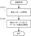
次に、可視光通信システム1の動作を説明する。図5は、可視光通信システム1内のサーバ100のマーカー200を用いた送信処理の動作の一例を示すフローチャートである。
Next, the operation of the visible
サーバ100の制御部102内のマーカー制御部112は、マーカー200の発光パターンを取得する(ステップS101)。発光パターンは、マーカー200−0〜200−3毎に設けられており、輝度、色相、これら輝度及び色相で発光させる時間を時系列で示す。発光パターンの情報は、例えばメモリ104に記憶されている。マーカー制御部112は、メモリ104に記憶されている発光パターンの情報を読み出す。本実施形態では、マーカー200−0は基準信号を送信するために用いられ、マーカー200−1〜200−3は数値信号を送信するために用いられる。ここで、基準信号は、複数の数値信号が示す数値の関係を示す関連情報であり、数値信号が示す数値毎の単位、信号を送信するマーカー200の数、後述する統合情報の表示態様等の情報(対応コンテンツ)と1対1に対応するIDである。IDと対応コンテンツは対応付けられてサーバ100内のメモリ104に記憶されている。
The
図6は、発光パターンの一例を示す図である。図6に示す発光パターンでは、マーカー200−0は、ヘッダとして消灯(Bk)し、次に、識別子として基準信号であることを示す赤(R)の発光を行い、次に、基準信号のデータとして赤、緑(G)、青(B)の何れかの発光を所定回数(例えば8回)繰り返し、その後、パリティとして赤、緑、青の何れかの発光を行う。マーカー200−1〜200−3は、ヘッダとして消灯し、次に、識別子として数値信号であることを示す緑の発光を行い、次に、数値信号のデータとして赤、緑、青の何れかの発光を所定回数(例えば8回)繰り返し、その後、パリティとして赤、緑、青の何れかの発光を行う。発光周期は例えば100(msec)である。 FIG. 6 is a view showing an example of a light emission pattern. In the light emission pattern shown in FIG. 6, the marker 200-0 turns off (Bk) as a header, and then emits red (R) light indicating that it is a reference signal as an identifier, and then data of the reference signal As red, green (G) or blue (B) light emission is repeated a predetermined number of times (for example, eight times), and then red, green or blue light emission is performed as a parity. The markers 200-1 to 200-3 turn off as a header, and then emit green light indicating that it is a numerical signal as an identifier, and next, any one of red, green and blue as data of the numerical signal The light emission is repeated a predetermined number of times (for example, eight times), and then red, green, or blue light is emitted as a parity. The light emission cycle is, for example, 100 (msec).
次に、マーカー制御部112は、発光パターンに応じて、マーカー200−0〜200−3の発光を制御する(ステップS102)。具体的には、マーカー制御部112は、マーカー200−0〜200−3毎に、発光パターンに応じたタイミングで、その発光パターンに応じた輝度及び色相の情報を有線通信部108へ出力するとともに、送信先のマーカー200に対応するIP(Internet Protocol)アドレス及びMAC(Media Access Control)アドレス等を有線通信部108へ出力する。有線通信部108は、マーカー200に対応するIPアドレス及びMACアドレス等を宛先として、輝度及び色相の情報を送信する。
Next, the
マーカー200内の有線通信部207は、マーカー200に対応するIPアドレス及びMACアドレス等を宛先とする輝度及び色相の情報を受信し、制御部202へ出力する。制御部202は、輝度及び色相の情報を符号化・変調部210へ出力する。符号化・変調部210は、制御部202から出力されたタグIDに対する符号化したビットデータ列を生成するとともに、ビットデータ列に基づくデジタル変調を行う。駆動部212は、符号化・変調部210から出力される信号に対応し、LED214が発する光の輝度を時間的に変化させるための駆動信号を生成する。LED214は、駆動部212から出力される駆動信号に応じて、時間的に輝度及び色相が変化する光を発する。
The
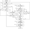
図7は、携帯機器300による受信処理の動作の一例を示すフローチャートである。図7に示すフローチャートは、マーカー200が図6に示す発光パターンに応じた発光を行う場合の動作を示す。
FIG. 7 is a flow chart showing an example of the operation of reception processing by the
携帯機器300の制御部302内のマーカー検出部332は、マーカー200−0からの光を受光したことによる基準信号を受信したか否かを判定する(ステップS201)。具体的には、マーカー検出部332は、例えば、図8(A)に示すような複数のフレームのそれぞれにおける同一座標の輝度を判別する。判別の結果、撮像画角内の所定の座標における輝度が、あるフレームでは第1の所定値以上であり、他のフレームでは第2の所定値以下となるというように大きく変化する場合には、当該所定の座標は、マーカー200(マーカー200−0〜200−3)の何れかからの光を受光することにより生じる変調像領域(図8(A)の変調像領域3070〜3073)の何れかのものであると見なされる。変調像領域が存在すると見なされた場合には、マーカー検出部332は、その変調像領域をマーカー200に対応するものであると判断する。更に、マーカー検出部332は、変調像領域の発光パターンが図6のマーカー200−0(LED0)の発光パターンであるか否かを判定する。変調像領域が複数存在する場合、換言すれば、複数のマーカー200が検出された場合には、マーカー検出部332は、複数の変調像領域の何れかの発光パターンが図6のマーカー200−0(LED0)によるものか否かを判定する。
The
基準信号が受信されていない場合(ステップS201;NO)、マーカー検出部332は、マーカー200−1〜200−3の少なくとも何れかからの光を受光したことによる数値信号を受信したか否かを判定する(ステップS202)。具体的には、ステップS201と同様、マーカー検出部332は、複数のフレームのそれぞれにおける同一座標の輝度を判別する。判別の結果、撮像画角内の所定の座標における輝度が、あるフレームでは第1の所定値以上であり、他のフレームでは第2の所定値以下となるというように大きく変化する場合には、当該所定の座標は、マーカー200からの光を受光することにより生じる変調像領域のものであると見なされる。変調像領域が存在すると見なされた場合には、マーカー検出部332は、その変調像領域を1つのマーカー200によるものであると判断する。更に、マーカー検出部332は、変調像領域の発光パターンが図6のマーカー200−1(LED1)、マーカー200−2(LED2)、マーカー200−3(LED3)の何れかの発光パターンであるか否かを判定する。変調像領域が複数存在する場合、換言すれば、複数のマーカー200が検出された場合には、マーカー検出部332は、複数の変調像領域の何れかの発光パターンが図6のマーカー200−1(LED1)、マーカー200−2(LED2)、マーカー200−3(LED3)の何れかの発光パターンであるか否かを判定する。
When the reference signal is not received (step S201; NO), the
数値信号が受信されていない場合(ステップS202;NO)、マーカー検出部332は、受信が中断したか否かを判定する(ステップS203)。例えば、フレーム内に変調像領域が存在しない場合や、当初はフレーム内に変調像領域が存在したが、途中で存在しなくなった場合には、マーカー検出部332は、受信が中断したと判定する。受信が中断した場合には(ステップS203;YES)、受信処理が終了し、受信が中断していない場合には(ステップS203;NO)、ステップS201以降の動作が繰り返される。
When the numerical signal is not received (step S202; NO), the
一方、数値信号が受信された場合(ステップS202;YES)、制御部302内の情報取得部336及び出力制御部338は、数値信号を受信したことを通知するための吹き出し画像の表示を行う(ステップS204)。具体的には、情報取得部336は、復号処理を行うことにより、フレーム内の変調像領域であるマーカー200の発光パターンと1対1に対応する数値を取得する。出力制御部338は、フレーム内の数値信号に対応する変調像領域であるマーカー200の位置に、そのマーカー200に対応する数値と受信ステータスを表示する制御を行う。これにより、例えば、図8(A)におけるフレーム内の数値信号に対応する変調像領域3073の位置に、図8(B)に示すように、重ねて数値と受信ステータスを含んだ吹き出し画像3074、すなわち、「10000 ID受信待機中」が表示される。
On the other hand, when a numerical signal is received (step S202; YES), the
次に、情報取得部336は、マーカー200−0からの光を受光したことによる基準信号を受信済みであるか否かを判定する(ステップS205)。具体的には、情報取得部336は、後述するステップS208及びステップS209の何れかとステップS210とが既に行われており、基準信号が示すIDと1対1に対応する情報(対応コンテンツ)がメモリ304に記憶されている場合には、基準信号を受信済みであると判定し、対応コンテンツがメモリ304に記憶されていない場合には、基準信号を受信済みでないと判定する。基準信号を受信済みでない場合には(ステップS205;NO)、ステップS201以降の動作が繰り返される。
Next, the
一方、ステップS201において基準信号を受信したと判定された場合(ステップS201;YES)、制御部302内の情報取得部336及び出力制御部338は、基準信号を受信したことを通知するための吹き出し画像の表示を行う(ステップS206)。具体的には、情報取得部336は、復号処理を行うことにより、フレーム内の基準信号に対応する変調像領域に対応するマーカー200−0の発光パターンからIDを取得する。出力制御部338は、フレーム内の基準信号に対応する変調像領域の位置に、IDを受信中である旨を表示する制御を行う。これにより、例えば、図8(A)におけるフレーム内の基準信号に対応する変調像領域3070の位置に、図8(C)に示すように、重ねてID受信中であることを示す吹き出し画像3075が表示される。
On the other hand, when it is determined in step S201 that the reference signal has been received (step S201; YES), the
次に、情報取得部336は、基準信号が示すIDと1対1に対応する対応コンテンツを携帯機器300内のメモリ304に保持しているか否かを判定する(ステップS207)。例えば、メモリ304に対応コンテンツが記憶されている場合には、対応コンテンツと当該対応コンテンツと1対1に対応するIDとが対応付けられている。情報取得部336は、メモリ304に、基準信号が示すIDに対応付けられている対応コンテンツが記憶されているか否かを判定する。
Next, the
対応コンテンツがメモリ304に保持されている場合には(ステップS207;YES)、情報取得部336は、メモリ304から基準信号が示すIDと1対1に対応する対応コンテンツを読み出す(ステップS208)。一方、対応コンテンツがメモリ304に保持されていない場合には(ステップS207;NO)、情報取得部336は、無線通信部308及びアンテナ310を介してサーバ100との間で通信を行い、基準信号が示すIDを送信することにより、サーバ100に対して基準信号が示すIDと1対1に対応する対応コンテンツを要求する。サーバ100は、この要求に応じて基準信号が示すIDと1対1に対応する対応コンテンツを送信する。情報取得部336は、サーバ100からの対応コンテンツを受信する(ステップS209)。受信された対応コンテンツは、基準信号が示すIDと対応付けられてメモリ304に記憶される。
If the corresponding content is held in the memory 304 (step S207; YES), the
ステップS208における対応コンテンツの読み出し、又は、ステップS209におけるサーバ100からの対応コンテンツの受信後、情報取得部336は、対応コンテンツに含まれる、信号を送信するマーカー200の数の情報に基づいて信号の数を特定する(ステップS210)。ここで、信号の数とは、マーカー200の数を意味する。
After the reading of the corresponding content in step S208 or the reception of the corresponding content from the
ステップS210における信号数の特定後、又は、ステップS205において基準信号を受信済みであると判定された後(ステップS205;YES)、情報取得部336は、ステップS210において特定した信号数に基づいて、全ての信号を受信済みであるか否かを判定する(ステップS211)。具体的には、情報取得部336は、受信した基準信号と数値信号との合計数がステップS210において特定した信号数と一致する場合には、全ての信号を受信済みであると判定する。
After the identification of the number of signals in step S210, or after it is determined that the reference signal has been received in step S205 (step S205; YES), the
全ての信号を受信済みでない場合(ステップS211;NO)、ステップS201以降の動作が繰り返される。一方、全ての信号を受信済みである場合(ステップS211;YES)、出力制御部338は、フレーム内の変調像領域であるマーカー200の位置に重ねて表示されている各吹き出し画像を消去する(ステップS212)。
If all the signals have not been received (step S211; NO), the operations after step S201 are repeated. On the other hand, when all the signals have been received (step S211; YES), the
更に、情報取得部336及び出力制御部338は、全ての基準信号及び数値信号を統合した吹き出し画像の表示を行う(ステップS213)。具体的には、情報取得部336は、基準信号に対応する対応コンテンツに含まれる数値の単位と、複数の数値信号に対応する複数の数値のうち、その単位で表される数値とを対応付ける。出力制御部338は、フレーム内の変調像領域のうち、基準信号に対応する変調像領域の位置に、基準信号に対応する対応コンテンツに含まれる統合情報の表示態様で、複数の数値と、当該数値の単位とを含んだ吹き出し画像を表示する制御を行う。これにより、例えば、図8(D)に示すように、フレーム内の基準信号に対応する変調像領域3070の近傍の位置に複数の数値(0、100、10000)と、当該数値の単位(g、SN、無し)とが表示された吹き出し画像3076が表示される。
Further, the
このように本実施形態では、マーカー200−0〜200−3は、サーバ100の制御に従って発光パターンに応じた発光を行う。一方、携帯機器300は、マーカー200−0〜200−3の発光態様に基づいて、基準信号と数値信号とを判別し、数値信号の受信時には、フレーム内のその数値信号に対応するマーカー200の位置(変調像領域の位置)に数値を表示し、基準信号の受信時には、フレーム内のその基準信号に対応するマーカー200−0の位置(変調像領域の位置)にIDの受信中である旨を表示する。更に、携帯機器300は、全ての基準信号及び数値信号を受信したタイミングで、フレーム内のマーカー200−0の位置(変調像領域の位置)に、複数の数値と、当該数値の単位とを統合して表示する。このため、携帯機器300は、複数のマーカー200からの受光タイミングについて同期を取る必要がなく、更には、マーカー200の数や配置が変更されても携帯機器300は調整を行う必要がなく、柔軟性を高くすることができる。また、数値信号や基準信号の受信の都度、その信号の送信元であるマーカー200の位置に受信した旨が表示されるため、ユーザが受信状況を把握しやすくなる。
Thus, in the present embodiment, the markers 200-0 to 200-3 emit light according to the light emission pattern according to the control of the
なお、本発明は、上記実施形態の説明及び図面によって限定されるものではなく、上記実施形態及び図面に適宜変更等を加えることは可能である。 The present invention is not limited by the above description of the embodiments and the drawings, and appropriate modifications and the like can be added to the embodiments and the drawings.
例えば、上述した実施形態では、マーカー200−0〜200−3は、図1に示すように、直線上に4つのマーカー200が配置される。しかし、マーカー200の数は2以上であればよいし、例えば、図9に示す可視光通信システム2のように、マーカー200−0〜200−3が配置されていてもよい。図6に示すように、基準信号の発光パターンと数値信号の発光パターンとが異なっており、複数のマーカー200のうち何れかが基準信号の送信元となり、他が数値信号の送信元であれば、マーカー200の数や配置は限定されない。
For example, in the embodiment described above, as shown in FIG. 1, the markers 200-0 to 200-3 have four
また、上述した実施形態では、可視光である赤(R)、緑(G)、青(B)の光を通信に用いる場合について説明したが、他の色の可視光を用いてもよく、更には、赤外線等の可視光以外の光を用いてもよい。 Further, in the embodiment described above, the case of using red (R), green (G) and blue (B) lights which are visible lights for communication has been described, but visible lights of other colors may be used, Furthermore, light other than visible light such as infrared may be used.
また、マーカー200内の光源はLEDに限定されない。例えば、表示装置を構成するLCD、PDP、ELディスプレイ等の一部に光源が構成されていてもよい。
Also, the light source in the
また、携帯機器300は、撮像が可能であれば、どのような装置でもよい。例えば、PHS(Personal Handy-phone System)、PDA(Personal Digital Assistant又はPersonal Data Assistance)、タブレットPC(Personal Computer)、ゲーム機器、携帯型音楽再生装置等であってもよい。
The
また、携帯機器300の機能とマーカー200の機能とを両方備える装置を用意し、場面に応じて、両機能を使い分けることができるようにしてもよい。
Alternatively, a device having both the function of the
また、上記実施形態において、実行されるプログラムは、フレキシブルディスク、CD−ROM(Compact Disc Read-Only Memory)、DVD(Digital Versatile Disc)、MO(Magneto-Optical disc)等のコンピュータで読み取り可能な記録媒体に格納して配布し、そのプログラムをインストールすることにより、上述の処理を実行するシステムを構成することとしてもよい。 In the above embodiment, the program to be executed may be a computer readable recording such as a flexible disk, a compact disc read only memory (CD-ROM), a digital versatile disc (DVD), a magneto optical disc (MO) or the like. By storing and distributing in a medium and installing the program, a system that executes the above-described processing may be configured.
また、プログラムをインターネット等のネットワークNW上の所定のサーバが有するディスク装置等に格納しておき、例えば、搬送波に重畳させて、ダウンロード等するようにしてもよい。 Also, the program may be stored in a disk device or the like possessed by a predetermined server on a network NW such as the Internet, and may be, for example, superimposed on a carrier wave and downloaded or the like.
なお、上述の機能を、OS(Operating System)が分担して実現する場合又はOSとアプリケーションとの協働により実現する場合等には、OS以外の部分のみを媒体に格納して配布してもよく、また、ダウンロード等してもよい。 When the OS (Operating System) shares and realizes the above functions, or when the OS and an application cooperate to realize it, etc., only the part other than the OS may be stored and distributed in the medium. Well, you may download it.
以上、本発明の好ましい実施形態について説明したが、本発明は係る特定の実施形態に限定されるものではなく、本発明には、特許請求の範囲に記載された発明とその均等の範囲が含まれる。以下に、本願出願の当初の特許請求の範囲に記載された発明を付記する。 Although the preferred embodiments of the present invention have been described above, the present invention is not limited to the specific embodiments, and the present invention includes the invention described in the claims and the equivalents thereof. Be In the following, the invention described in the original claims of the present application is appended.
(付記1)
可視光通信用のマーカーが発する光を受光する受光手段と、
前記受光手段により受光された光に基づいて情報へ復号する復号手段と、
前記受光手段により受光された光が所定の関係を有する複数の光である場合に、その旨を報知する報知手段と、
を備えることを特徴とする情報復号装置。
(Supplementary Note 1)
Light receiving means for receiving light emitted by the marker for visible light communication;
A decoding unit that decodes information into information based on light received by the light receiving unit;
Informing means for informing when the light received by the light receiving means is a plurality of lights having a predetermined relationship, and
An information decoding apparatus comprising:
(付記2)
前記報知手段は、前記複数の光から復号された複数の情報を統合した内容を報知することを特徴とする付記1に記載の情報復号装置。
(Supplementary Note 2)
The information decoding apparatus according to
(付記3)
前記複数の光を全て受光する以前に、前記復号手段により復号された情報が存在する場合、前記情報が存在することを報知するように前記報知手段を制御する報知制御手段を更に備えることを特徴とする付記1又は2に記載の情報復号装置。
(Supplementary Note 3)
The information processing apparatus further comprises notification control means for controlling the notification means to notify that the information exists if the information decoded by the decoding means exists before all the plurality of lights are received. The information decoding device according to
(付記4)
前記報知制御手段は、前記復号手段により復号された情報と、前記情報に対応する光とを対応付けて出力するように前記報知手段を制御することを特徴とする付記3に記載の情報復号装置。
(Supplementary Note 4)
The information decoding apparatus according to claim 3, wherein the notification control unit controls the notification unit to output the information decoded by the decoding unit and the light corresponding to the information. .
(付記5)
前記受光手段は、撮像手段を含むことを特徴とする付記1乃至4の何れか1つに記載の情報復号装置。
(Supplementary Note 5)
The information decoding apparatus according to any one of
(付記6)
前記報知手段は、前記撮像手段により撮像された画像を表示するとともに、前記画像に含まれる前記複数の光の位置に、前記光に対応する前記情報を表示する表示手段を含むことを特徴とする付記5に記載の情報復号装置。
(Supplementary Note 6)
The notification means includes a display means for displaying the image captured by the imaging means and displaying the information corresponding to the light at the positions of the plurality of lights included in the image. The information decoding device according to appendix 5.
(付記7)
可視光通信用のマーカーが発する光を受光する受光ステップと、
前記受光ステップにて受光された光に基づいて情報へ復号する復号ステップと、
前記受光ステップにて受光された光が所定の関係を有する複数の光である場合に、その旨を報知する報知ステップと、
を含むことを特徴とする情報復号方法。
(Appendix 7)
A light receiving step of receiving light emitted from the marker for visible light communication;
A decoding step of decoding into information based on the light received in the light receiving step;
A notifying step for notifying that effect when the light received in the light receiving step is a plurality of lights having a predetermined relationship;
An information decoding method characterized by including:
(付記8)
コンピュータを、
可視光通信用のマーカーが発する光を受光する受光手段、
前記受光手段によって受光された光に基づいて情報へ復号する復号手段、
前記受光手段により受光された光が所定の関係を有する複数の光である場合に、その旨を報知をする報知手段、
として機能させることを特徴とするプログラム。
(Supplementary Note 8)
Computer,
Light receiving means for receiving light emitted by a marker for visible light communication,
Decoding means for decoding into information based on light received by the light receiving means,
Informing means for notifying that effect when the light received by the light receiving means is a plurality of lights having a predetermined relationship,
A program characterized by acting as
1、2…可視光通信システム、100…サーバ、200、200−0〜200−3…マーカー、102、202、302…制御部、104、204、304…メモリ、106、306…操作部、107、307…表示部、108、207…有線通信部、112…マーカー制御部、210……符号化・変調部、212…駆動部、214…LED、300…携帯機器、308…無線通信部、310…アンテナ、312…レンズ、314…撮像部、315…受光面、316…画像処理部、322…GPS受信機、324…方位センサ、326…傾斜センサ、328…加速度センサ、332…マーカー検出部、336…情報取得部、338…出力制御部、400…ユーザ、500…通信ネットワーク、3070〜3073…変調像領域、3074〜3076…吹き出し画像
1, 2 ... visible light communication system, 100 ... server, 200, 200-0 to 200-3 ... marker, 102, 202, 302 ... control unit, 104, 204, 304 ... memory, 106, 306 ... operation unit, 107 307: display unit 108: 207 wired communication unit 112: marker control unit 210: coding / modulation unit 212: drive unit 214: LED 300: portable device 308:
Claims (7)
前記受光手段により夫々受光された光に基づいて、前記複数のマーカーが発した情報へ夫々復号する復号手段と、
前記復号手段によって復号された情報を出力する出力手段と、
前記復号手段によって復号された複数の情報に、所定の情報が含まれているか否かを判断する判断手段と、
前記判断手段により前記所定の情報が含まれていないと判断された場合に前記復号手段によって夫々復号された情報を出力するよう前記出力手段を制御する第1の出力制御手段と、
前記判断手段により前記所定の情報が含まれていると判断された場合に夫々復号された前記情報を統合した情報を出力するよう前記出力手段を制御する第2の出力制御手段と、
を備えることを特徴とする情報復号装置。 Light receiving means for respectively receiving light emitted by a plurality of markers for visible light communication;
And decoding means for respectively decoding information emitted by the plurality of markers based on the light respectively received by the light receiving means;
Output means for outputting the information decoded by the decoding means;
A determination unit that determines whether or not predetermined information is included in the plurality of pieces of information decoded by the decoding unit;
First output control means for controlling the output means to output the information respectively decoded by the decoding means when it is judged by the judgment means that the predetermined information is not included;
Second output control means for controlling the output means to output information obtained by integrating the decoded information when it is determined by the determination means that the predetermined information is included;
An information decoding apparatus comprising:
前記受光手段により夫々受光された光に基づいて、前記複数のマーカーが発した情報へ夫々復号する復号手段と、
前記復号手段によって復号された情報を出力する出力手段と、
前記復号手段によって夫々復号された情報を出力するよう前記出力手段を制御する第1の出力制御手段と、
前記復号された複数の情報に所定の情報が含まれ、且つ、前記第1の出力制御手段により前記夫々復号された情報が出力されるよう前記出力手段が制御されている場合に、これに代えて、夫々復号された前記情報を統合した情報を出力するよう前記出力手段を制御する第2の出力制御手段と、
を備えることを特徴とする情報復号装置。 Light receiving means for respectively receiving light emitted by a plurality of markers for visible light communication;
And decoding means for respectively decoding information emitted by the plurality of markers based on the light respectively received by the light receiving means;
Output means for outputting the information decoded by the decoding means;
First output control means for controlling the output means to output the information respectively decoded by the decoding means;
In the case where the output means is controlled such that predetermined information is included in the plurality of pieces of decoded information and the information decoded by the first output control means is output, And second output control means for controlling the output means to output information obtained by integrating the decoded information.
An information decoding apparatus comprising:
前記受光ステップにて夫々受光された光に基づいて、前記複数のマーカーが発した情報へ夫々復号する復号ステップと、
前記復号ステップにて復号された複数の情報に、所定の情報が含まれているか否かを判断する判断ステップと、
前記判断ステップにて前記所定の情報が含まれていないと判断された場合に前記復号ステップにて夫々復号された情報を出力するよう出力部を制御する第1の出力制御ステップと、
前記判断ステップにて前記所定の情報が含まれていると判断された場合に夫々復号された前記情報を統合した情報を出力するよう前記出力部を制御する第2の出力制御ステップと、
を含むことを特徴とする情報復号方法。 A light receiving step of respectively receiving light emitted from a plurality of markers for visible light communication;
A decoding step of decoding information respectively emitted from the plurality of markers based on the light respectively received in the light receiving step;
A determination step of determining whether predetermined information is included in the plurality of pieces of information decoded in the decoding step;
A first output control step of controlling an output unit to output information decoded respectively in the decoding step when it is judged in the judgment step that the predetermined information is not included;
A second output control step of controlling the output unit to output information in which the decoded information is integrated when it is determined that the predetermined information is included in the determination step;
An information decoding method characterized by including:
前記受光部に対し、可視光通信用の複数のマーカーが発する光を夫々受光させる受光手段、
前記受光手段により夫々受光された光に基づいて、前記複数のマーカーが発した情報へ夫々復号する復号手段、
前記復号手段によって復号された情報を前記情報出力部にて出力させる出力手段、
前記復号手段によって復号された複数の情報に、所定の情報が含まれているか否かを判断する判断手段、
前記判断手段により前記所定の情報が含まれていないと判断された場合に前記復号手段によって夫々復号された情報を出力するよう前記出力手段を制御する第1の出力制御手段、
前記判断手段により前記所定の情報が含まれていると判断された場合に夫々復号された前記情報を統合した情報を出力するよう前記出力手段を制御する第2の出力制御手段、
として機能させることを特徴とするプログラム。 A computer provided in an apparatus including a light receiving unit and an information output unit ;
A light receiving unit that causes the light receiving unit to respectively receive light emitted by a plurality of markers for visible light communication;
Decoding means for respectively decoding information emitted by the plurality of markers based on the light respectively received by the light receiving means;
An output unit that causes the information output unit to output the information decoded by the decoding unit;
A determination unit that determines whether a plurality of pieces of information decoded by the decoding unit include predetermined information;
First output control means for controlling the output means to output information respectively decoded by the decoding means when it is judged by the judgment means that the predetermined information is not included;
Second output control means for controlling the output means to output information obtained by integrating the decoded information when it is determined by the determination means that the predetermined information is included;
A program characterized by acting as
Priority Applications (3)
| Application Number | Priority Date | Filing Date | Title |
|---|---|---|---|
| JP2015127038A JP6540271B2 (en) | 2015-06-24 | 2015-06-24 | Information decryption apparatus, information decryption method and program |
| US15/067,065 US10389443B2 (en) | 2015-06-24 | 2016-03-10 | Decoding apparatus, decoding method and non-transitory computer readable recording medium |
| CN201610171693.XA CN106301562B (en) | 2015-06-24 | 2016-03-24 | Information decoding device and information decoding method |
Applications Claiming Priority (1)
| Application Number | Priority Date | Filing Date | Title |
|---|---|---|---|
| JP2015127038A JP6540271B2 (en) | 2015-06-24 | 2015-06-24 | Information decryption apparatus, information decryption method and program |
Publications (3)
| Publication Number | Publication Date |
|---|---|
| JP2017011591A JP2017011591A (en) | 2017-01-12 |
| JP2017011591A5 JP2017011591A5 (en) | 2018-05-17 |
| JP6540271B2 true JP6540271B2 (en) | 2019-07-10 |
Family
ID=57601569
Family Applications (1)
| Application Number | Title | Priority Date | Filing Date |
|---|---|---|---|
| JP2015127038A Active JP6540271B2 (en) | 2015-06-24 | 2015-06-24 | Information decryption apparatus, information decryption method and program |
Country Status (3)
| Country | Link |
|---|---|
| US (1) | US10389443B2 (en) |
| JP (1) | JP6540271B2 (en) |
| CN (1) | CN106301562B (en) |
Families Citing this family (2)
| Publication number | Priority date | Publication date | Assignee | Title |
|---|---|---|---|---|
| CN111142985A (en) * | 2019-11-28 | 2020-05-12 | 南京艾凯特光电科技有限公司 | Optical writing text output device and control method thereof |
| DE102021004055A1 (en) | 2021-08-05 | 2021-12-02 | Daimler Ag | Method of heating a battery and battery |
Family Cites Families (10)
| Publication number | Priority date | Publication date | Assignee | Title |
|---|---|---|---|---|
| JP2003179556A (en) * | 2001-09-21 | 2003-06-27 | Casio Comput Co Ltd | Information transmission method, information transmission system, imaging device, and information transmission method |
| JP4867515B2 (en) * | 2006-07-28 | 2012-02-01 | カシオ計算機株式会社 | Image processing apparatus, image processing method, and image processing program |
| KR20080110489A (en) * | 2007-06-14 | 2008-12-18 | 소니 가부시끼 가이샤 | Information processing apparatus and method, and computer program |
| JP4552074B2 (en) | 2008-05-29 | 2010-09-29 | カシオ計算機株式会社 | Information transmission system, information decoding apparatus, notification method, and program |
| US9287976B2 (en) | 2011-07-26 | 2016-03-15 | Abl Ip Holding Llc | Independent beacon based light position system |
| JP5488583B2 (en) * | 2011-12-27 | 2014-05-14 | カシオ計算機株式会社 | Information providing system, server, information providing method, and program |
| JP5435067B2 (en) * | 2012-04-25 | 2014-03-05 | カシオ計算機株式会社 | Communication system, information terminal, communication method and program |
| JP5648664B2 (en) * | 2012-09-21 | 2015-01-07 | カシオ計算機株式会社 | Information processing system, information processing method, terminal device, and program |
| JP5928382B2 (en) * | 2013-03-21 | 2016-06-01 | カシオ計算機株式会社 | Imaging device, visible light communication control system, output control method, visible light communication control method, and program |
| CN203574655U (en) * | 2013-04-09 | 2014-04-30 | 北京半导体照明科技促进中心 | Device and system for transmitting information through visible light and light source |
-
2015
- 2015-06-24 JP JP2015127038A patent/JP6540271B2/en active Active
-
2016
- 2016-03-10 US US15/067,065 patent/US10389443B2/en active Active
- 2016-03-24 CN CN201610171693.XA patent/CN106301562B/en active Active
Also Published As
| Publication number | Publication date |
|---|---|
| CN106301562B (en) | 2019-05-31 |
| US10389443B2 (en) | 2019-08-20 |
| JP2017011591A (en) | 2017-01-12 |
| US20160380697A1 (en) | 2016-12-29 |
| CN106301562A (en) | 2017-01-04 |
Similar Documents
| Publication | Publication Date | Title |
|---|---|---|
| US8913885B2 (en) | Information provision system, server, terminal device, information provision method, display control method and recording medium | |
| US9331778B2 (en) | Information provision system, server system, terminal device, information provision method, and recording medium | |
| US9705596B2 (en) | Optical communication apparatus, wavelength band estimating apparatus, optical communication method and storage medium | |
| JP5648664B2 (en) | Information processing system, information processing method, terminal device, and program | |
| JP5928382B2 (en) | Imaging device, visible light communication control system, output control method, visible light communication control method, and program | |
| JP2013236363A (en) | Display device and program | |
| US10218439B2 (en) | Optical communication device, optical communication method, and non-transitory recording medium | |
| JP6540271B2 (en) | Information decryption apparatus, information decryption method and program | |
| US10264228B2 (en) | Decoding apparatus, decoding method, and non-transitory recording medium | |
| JP6540132B2 (en) | Decryption device, decryption method, and program | |
| JP5921496B2 (en) | Terminal device, display control method, and program | |
| JP6390257B2 (en) | Information processing system, display device, display control method, and program | |
| JP6693365B2 (en) | Notification device, notification method, and program | |
| JP6600934B2 (en) | Information processing system, communication apparatus, and program | |
| KR20160002358A (en) | Electronic device, information control method, and non-transitory computer-readable recording medium | |
| JP2015188189A (en) | Identification device, identification method, and program |
Legal Events
| Date | Code | Title | Description |
|---|---|---|---|
| A521 | Request for written amendment filed |
Free format text: JAPANESE INTERMEDIATE CODE: A523 Effective date: 20180326 |
|
| A621 | Written request for application examination |
Free format text: JAPANESE INTERMEDIATE CODE: A621 Effective date: 20180326 |
|
| A131 | Notification of reasons for refusal |
Free format text: JAPANESE INTERMEDIATE CODE: A131 Effective date: 20181016 |
|
| A521 | Request for written amendment filed |
Free format text: JAPANESE INTERMEDIATE CODE: A523 Effective date: 20181214 |
|
| TRDD | Decision of grant or rejection written | ||
| A01 | Written decision to grant a patent or to grant a registration (utility model) |
Free format text: JAPANESE INTERMEDIATE CODE: A01 Effective date: 20190514 |
|
| A61 | First payment of annual fees (during grant procedure) |
Free format text: JAPANESE INTERMEDIATE CODE: A61 Effective date: 20190527 |
|
| R150 | Certificate of patent or registration of utility model |
Ref document number: 6540271 Country of ref document: JP Free format text: JAPANESE INTERMEDIATE CODE: R150 |