US10264228B2 - Decoding apparatus, decoding method, and non-transitory recording medium - Google Patents
Decoding apparatus, decoding method, and non-transitory recording medium Download PDFInfo
- Publication number
- US10264228B2 US10264228B2 US15/041,791 US201615041791A US10264228B2 US 10264228 B2 US10264228 B2 US 10264228B2 US 201615041791 A US201615041791 A US 201615041791A US 10264228 B2 US10264228 B2 US 10264228B2
- Authority
- US
- United States
- Prior art keywords
- color
- area
- image
- brightness saturation
- signal
- Prior art date
- Legal status (The legal status is an assumption and is not a legal conclusion. Google has not performed a legal analysis and makes no representation as to the accuracy of the status listed.)
- Active, expires
Links
Images


Classifications
-
- H—ELECTRICITY
- H04—ELECTRIC COMMUNICATION TECHNIQUE
- H04N—PICTORIAL COMMUNICATION, e.g. TELEVISION
- H04N19/00—Methods or arrangements for coding, decoding, compressing or decompressing digital video signals
- H04N19/10—Methods or arrangements for coding, decoding, compressing or decompressing digital video signals using adaptive coding
- H04N19/169—Methods or arrangements for coding, decoding, compressing or decompressing digital video signals using adaptive coding characterised by the coding unit, i.e. the structural portion or semantic portion of the video signal being the object or the subject of the adaptive coding
- H04N19/182—Methods or arrangements for coding, decoding, compressing or decompressing digital video signals using adaptive coding characterised by the coding unit, i.e. the structural portion or semantic portion of the video signal being the object or the subject of the adaptive coding the unit being a pixel
-
- H—ELECTRICITY
- H04—ELECTRIC COMMUNICATION TECHNIQUE
- H04N—PICTORIAL COMMUNICATION, e.g. TELEVISION
- H04N9/00—Details of colour television systems
- H04N9/64—Circuits for processing colour signals
- H04N9/68—Circuits for processing colour signals for controlling the amplitude of colour signals, e.g. automatic chroma control circuits
-
- H—ELECTRICITY
- H04—ELECTRIC COMMUNICATION TECHNIQUE
- H04B—TRANSMISSION
- H04B10/00—Transmission systems employing electromagnetic waves other than radio-waves, e.g. infrared, visible or ultraviolet light, or employing corpuscular radiation, e.g. quantum communication
- H04B10/11—Arrangements specific to free-space transmission, i.e. transmission through air or vacuum
- H04B10/114—Indoor or close-range type systems
- H04B10/116—Visible light communication
-
- H—ELECTRICITY
- H04—ELECTRIC COMMUNICATION TECHNIQUE
- H04B—TRANSMISSION
- H04B10/00—Transmission systems employing electromagnetic waves other than radio-waves, e.g. infrared, visible or ultraviolet light, or employing corpuscular radiation, e.g. quantum communication
- H04B10/50—Transmitters
-
- H—ELECTRICITY
- H04—ELECTRIC COMMUNICATION TECHNIQUE
- H04N—PICTORIAL COMMUNICATION, e.g. TELEVISION
- H04N19/00—Methods or arrangements for coding, decoding, compressing or decompressing digital video signals
- H04N19/10—Methods or arrangements for coding, decoding, compressing or decompressing digital video signals using adaptive coding
- H04N19/169—Methods or arrangements for coding, decoding, compressing or decompressing digital video signals using adaptive coding characterised by the coding unit, i.e. the structural portion or semantic portion of the video signal being the object or the subject of the adaptive coding
- H04N19/186—Methods or arrangements for coding, decoding, compressing or decompressing digital video signals using adaptive coding characterised by the coding unit, i.e. the structural portion or semantic portion of the video signal being the object or the subject of the adaptive coding the unit being a colour or a chrominance component
-
- H—ELECTRICITY
- H04—ELECTRIC COMMUNICATION TECHNIQUE
- H04N—PICTORIAL COMMUNICATION, e.g. TELEVISION
- H04N23/00—Cameras or camera modules comprising electronic image sensors; Control thereof
- H04N23/10—Cameras or camera modules comprising electronic image sensors; Control thereof for generating image signals from different wavelengths
- H04N23/12—Cameras or camera modules comprising electronic image sensors; Control thereof for generating image signals from different wavelengths with one sensor only
-
- H—ELECTRICITY
- H04—ELECTRIC COMMUNICATION TECHNIQUE
- H04N—PICTORIAL COMMUNICATION, e.g. TELEVISION
- H04N23/00—Cameras or camera modules comprising electronic image sensors; Control thereof
- H04N23/60—Control of cameras or camera modules
- H04N23/67—Focus control based on electronic image sensor signals
-
- H—ELECTRICITY
- H04—ELECTRIC COMMUNICATION TECHNIQUE
- H04N—PICTORIAL COMMUNICATION, e.g. TELEVISION
- H04N23/00—Cameras or camera modules comprising electronic image sensors; Control thereof
- H04N23/70—Circuitry for compensating brightness variation in the scene
- H04N23/71—Circuitry for evaluating the brightness variation
-
- H04N5/23212—
-
- H04N5/2351—
-
- H04N9/07—
-
- H—ELECTRICITY
- H04—ELECTRIC COMMUNICATION TECHNIQUE
- H04M—TELEPHONIC COMMUNICATION
- H04M1/00—Substation equipment, e.g. for use by subscribers
- H04M1/72—Mobile telephones; Cordless telephones, i.e. devices for establishing wireless links to base stations without route selection
- H04M1/724—User interfaces specially adapted for cordless or mobile telephones
- H04M1/72403—User interfaces specially adapted for cordless or mobile telephones with means for local support of applications that increase the functionality
- H04M1/72409—User interfaces specially adapted for cordless or mobile telephones with means for local support of applications that increase the functionality by interfacing with external accessories
- H04M1/72412—User interfaces specially adapted for cordless or mobile telephones with means for local support of applications that increase the functionality by interfacing with external accessories using two-way short-range wireless interfaces
-
- H04M1/7253—
Definitions
- the present disclosure relates to a decoding apparatus, a decoding method, and a non-transitory recording medium.
- a decoding apparatus includes:
- an image acquiring unit configured to continuously acquire an image including a color changing in time-series
- a processing unit configured to perform processing for a pixel area of brightness saturation in an image acquired continuously by the image acquiring unit to increase an image area including the color
- a decoding unit configured to decode information from a color of an image of which an area has been increased by the processing unit.
- a decoding method includes:
- a decoding step of decoding information from a color of an image of which an area has been increased in the processing step is a decoding step of decoding information from a color of an image of which an area has been increased in the processing step.
- a non-transitory recording medium is a computer-readable non-transitory recording medium recording a program to cause a computer to function as:
- an image acquiring unit configured to continuously acquire an image including a color changing in time-series
- a processing unit configured to perform processing for a pixel area of brightness saturation in an image acquired continuously by the image acquiring unit to increase an image area including the color
- a decoding unit configured to decode information from a color of an image of which an area has been increased by the processing unit.
- FIG. 1 is a diagram showing the configuration of an optical communication system according to an embodiment of the present disclosure
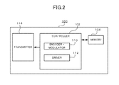
- FIG. 2 is a diagram showing the configuration of a transmission apparatus shown in FIG. 1 ;
- FIG. 3 is a diagram showing the configuration of a reception apparatus shown in FIG. 1 ;
- FIG. 4 is a diagram showing image processing in the reception apparatus
- FIG. 5 is a flowchart showing the operation of a reception process including first image processing in the reception apparatus.
- FIG. 6 is a flowchart showing the operation of a reception process including second image processing in the reception apparatus.
- an optical communication system 1 includes a transmission apparatus 100 and a reception apparatus 200 .
- the transmission apparatus 100 and the reception apparatus 200 can perform communication from the transmission apparatus 100 to the reception apparatus 200 with light as a communication medium.
- information to be communicated to the reception apparatus 200 is converted by modulation into and output as an optical signal changing in time-series of red (R), green (G), and blue (B) that are visible light.
- the reception apparatus 200 is, for example, a smart phone and receives an optical signal from the transmission apparatus 100 by imaging the transmission apparatus 100 included in an imaging range.
- the reception apparatus 200 displays an image obtained by imaging. With the reception apparatus 200 , information to be communicated is decoded from a received optical signal and displayed.
- the transmission apparatus 100 includes a controller 102 , a memory 104 , and a transmitter 114 .
- the controller 102 includes a central processing unit (CPU), executes software processing according to a program stored in the memory 104 , and functions to realize various functions provided to the transmission apparatus 100 .
- CPU central processing unit
- the memory 104 is, for example, a random-access memory (RAM) for a work area or a read-only memory (ROM) storing a basic operation program.
- the memory 104 stores various information (such as a program) used for control and/or the like in the transmission apparatus 100 .
- An encoder-modulator 110 within the controller 102 encodes information to be communicated into a bit data stream. Further, the encoder-modulator 110 performs digital modulation based on the bit data stream. For the modulation scheme, 4 pulse-position modulation (PPM) using a carrier wave at a frequency of 28.8 kHz is employed, for example. Based on a signal generated by the encoder-modulator 110 , a driver 112 within the controller 102 performs control with respect to the transmitter 114 such that light is changed temporally with a change cycle t 1 at the same brightness, among red (R), green (G), and blue (B) that are visible light with differing wavelengths.
- PPM pulse-position modulation
- the transmitter 114 is, for example, a light-emitting diode (LED).
- LED light-emitting diode
- the driver 112 Through control by the driver 112 , light of respective wavelengths for red (R), green (G), and blue (B) is output at the same brightness while being changed temporally with the change cycle t 1 .
- the reception apparatus 200 displays a taken image and also functions as a communication apparatus for receiving information from the transmission apparatus 100 .
- the reception apparatus 200 includes a controller 202 , a memory 204 , an operation unit 206 , a display 207 , a wireless communication module 208 , an antenna 210 , and an imager 214 .
- the controller 202 is configured of a CPU.
- the controller 202 functions to realize various functions provided to the reception apparatus 200 , by executing software processing according to a program stored in the memory 204 .
- the memory 204 is, for example a RAM or a ROM.
- the memory 204 stores various information (such as a program) used for control and/or the like in the reception apparatus 200 .
- the operation unit 206 is a touchscreen arranged on the upper surface of a display area of the display 207 and is an interface used for inputting operation content of a user.
- the display 207 is configured of, for example, a liquid crystal display (LCD), a plasma display panel (PDP), an electro-luminescence (EL) display, or the like and displays an image.
- LCD liquid crystal display
- PDP plasma display panel
- EL electro-luminescence
- the wireless communication module 208 is configured using, for example, a radio frequency (RF) circuit, a base band (BB) circuit, and/or the like.
- the wireless communication module 208 transmits and receives a radio signal via the antenna 210 .
- the wireless communication module 208 modulates a transmit signal and demodulates a receive signal.
- the imager 214 is disposed on an opposite surface to a surface on which the display 207 is installed in a casing of the reception apparatus 200 .
- the imager 214 includes a lens and photosensitive elements.
- the lens includes, for example, a zoom lens, and is actuated by the zoom control and focusing control by the controller 202 .
- the field angle of the imager 214 , and an optical image are controlled by the actuation of the lens.
- the photosensitive elements include a plurality of photosensitive elements arranged regularly and two-dimensionally on a photosensitive surface.
- the photosensitive elements are imaging devices, such as a photo diode, a Charge Coupled Device (CCD) built with color filters in a manner of Bayer arrangement or a three CCD type, or a Complementary Metal Oxide Semiconductor (CMOS).
- imaging devices such as a photo diode, a Charge Coupled Device (CCD) built with color filters in a manner of Bayer arrangement or a three CCD type, or a Complementary Metal Oxide Semiconductor (CMOS).
- CCD Charge Coupled Device
- CMOS Complementary Metal Oxide Semiconductor
- the imager 214 performs imaging with an imaging cycle t 1 identical to the change cycle t 1 for light in the transmitter 114 within the transmission apparatus 100 .
- the imager 214 takes an optical image of (receives) entered light at an angle of view of a predetermined range based on a control signal from the controller 202 and successively outputs an image signal within the angle of view to the controller 202 .
- an image generator 232 within the controller 202 converts the image signal to digital data to generate a frame.
- a display controller 236 within the controller 202 performs control of causing the display 207 to display an image corresponding to a frame.
- a decoder 234 within the controller 202 determines a part (change area) where there is a hue change due to a change in wavelength in frames that are input continuously in time-series. Specifically, the decoder 234 determines the lightness of each pixel within image data of a frame. Further, the decoder 234 assumes a pixel of which the lightness value is more than or equal to a predetermined value as a candidate (candidate area) for a part (change area) where there is a hue change due to reception of light of a wavelength corresponding to an emission color from the transmitter 114 within the transmission apparatus 100 . Further, the decoder 234 determines the hue in the same coordinates within a candidate area in each of a predetermined number of frames most recently acquired.
- the decoder 234 assumes the candidate area as a change area.
- the decoder 234 then acquires the hue value (type of wavelength) of the change area within a frame upon every imaging and determines the color of the change area corresponding to the hue value as one of red (R), green (G), and blue (B). Further, the decoder 234 decodes a bit data stream corresponding to each color of red (R), green (G), and blue (B) to acquire information to be communicated. Further, the display controller 236 performs control of causing the display 207 to display an image of the information to be communicated.
- FIG. 4 is a diagram showing the image processing.
- a light source portion within a frame includes a brightness saturation area 302 on the inside of an area (color area) 301 in the original color of the light source, and the area of the color area decreases from the original area.
- first image processing and second image processing are executed selectively.
- the decoder 234 performs processing of shifting the focus by moving the lens within the imager 214 and/or the like. Accordingly, a frame becomes a gradated image. As shown in section (B), the area of the color area 301 increases, and the area of the brightness saturation area 302 decreases.
- the decoder 234 executes a program to perform a filtering process (gradation filtering process) of an image.
- a filtering process processing of replacing the color of the brightness saturation area 302 with the color of the color area 301 surrounding the brightness saturation area 302 is performed. Accordingly, as shown in section (C), there is only the color area 301 .
- the operation of the optical communication system 1 will be described.
- a transmission process by the transmission apparatus 100 and a reception process by the reception apparatus 200 are performed.
- the encoder-modulator 110 within the controller 102 of the transmission apparatus 100 encodes information to be communicated into a bit data stream and further performs digital modulation based on the bit data stream.
- the driver 112 within the controller 102 performs control with respect to the transmitter 114 such that light is changed temporally with an emission cycle t 1 , among red (R), green (G), and blue (B). Accordingly, under the control of the driver 112 , the transmitter 114 outputs light of red (R), green (G), and blue (B) at the same brightness with the emission cycle t 1 , based on modulated information to be communicated.
- FIG. 5 is a flowchart showing the operation of a reception process including the first image processing by the reception apparatus 200 . Every time an image signal from the imager 214 is input, the image generator 232 within the controller 202 converts the image signal to digital data to generate a frame. The decoder 234 within the controller 202 determines whether there is a brightness saturation area 302 within the generated frame (step S 101 ).
- the decoder 234 determines the lightness and hue of each pixel forming the frame. Further, the decoder 234 determines whether a pixel (brightness saturation pixel) having a hue value of white with a lightness value more than or equal to a predetermined value exists, and a pixel (color pixel) having a hue value of one of red (R), green (G), and blue (B) exists surrounding the brightness saturation pixel. The decoder 234 determines that the brightness saturation area 302 exists in the case where a combination of a brightness saturation pixel and a color pixel surrounding thereof exists, and determines that the brightness saturation area 302 does not exist in the case where a combination of a brightness saturation pixel and a color pixel surrounding thereof does not exist.
- the decoder 234 performs focus shift process (step S 102 ) by moving the lens within the imager 214 and/or the like. Accordingly, as described above, the frame becomes a gradated image.
- the area of the color area 301 increases, and the area of the brightness saturation area 302 decreases.
- step S 102 After a focus shift process in step S 102 , or in the case where the brightness saturation area 302 is determined to not exist in step S 101 (S 101 : NO), the image generator 232 converts the image signal to digital data in real time to generate (acquire) a frame every time an image signal from the imager 214 is input, and the display controller 236 performs control of causing the display 207 to display an image corresponding to the frame (step S 103 ).
- the decoder 234 determines a part (change area: light source) where there is a hue change due to a change in wavelength in frames that are input continuously in time-series (step S 104 ).
- the decoder 234 acquires the hue value (type of wavelength) of the change area within the frame and determines the color of the change area corresponding to the hue value as one of red (R), green (G), and blue (B) (step S 105 ).
- the decoder 234 decodes a bit data stream corresponding to each color of red (R), green (G), and blue (B) to acquire information to be communicated (step S 106 ).
- control of causing the display 207 to display an image of the information to be communicated is performed.
- FIG. 6 is a flowchart showing the operation of a reception process including the second image processing by the reception apparatus 200 .
- the image generator 232 within the controller 202 converts the image signal to digital data to generate a frame.
- the decoder 234 within the controller 202 determines whether there is the brightness saturation area 302 within the generated frame (step S 201 ).
- the decoder 234 executes a program to perform a filtering process (gradation filtering process) of an image (step S 202 ).
- a filtering process as described above, processing of replacing the color of the brightness saturation area 302 with the color of the color area 301 surrounding the brightness saturation area 302 is performed.
- step S 201 After the gradation filtering process in step S 202 , or in the case where the brightness saturation area 302 is determined to not exist in step S 201 (step S 201 : NO), processing of steps S 203 to S 206 is performed.
- the processing of steps S 203 to S 206 is similar to processing of steps S 103 to S 106 in FIG. 5 , and therefore description is omitted.
- the decoder 234 within the reception apparatus 200 performs first image processing of shifting the focus by moving the lens within the imager 214 and/or the like and processing of replacing the color of the brightness saturation area 302 with the color of the color area 301 surrounding the brightness saturation area 302 through execution of a program to perform a filtering process (gradation filtering process) of an image, before determination of a change area, determination of the color of the change area, and decoding of bit string data, in the case where a phenomenon called brightness saturation occurs due to high brightness of light output from the transmission apparatus 100 and high lightness in a portion of the transmitter 114 (light source) within a frame obtained by imaging in the reception apparatus 200 .
- a filtering process gradient filtering process
- the first image processing and the second image processing decreases the area of the brightness saturation area 302 within the frame and increases the color area of red (R), green (G), or blue (B) that is the color of the light source. Therefore, the precision of determination of a change area, determination of the color of the change area, and decoding of bit string data can be improved.
- the transmitter 114 within the transmission apparatus 100 may be, for example, configured as a part of a display.
- the reception apparatus 200 may be any apparatus, as long as imaging is possible.
- a personal handy-phone system PDA
- PDA personal digital assistant or personal data assistance
- PC tablet personal computer
- game console a portable audio player, and the like are acceptable.
- An apparatus including both of the function of the reception apparatus 200 and the function of the transmission apparatus 100 may be prepared, so that the two functions can be used separately according to the situation.
- a program to be executed is stored for distribution in a non-transitory computer-readable recording medium, such as a flexible disk, a compact disc read-only memory (CD-ROM), a digital versatile disc (DVD), or a magneto-optical disc (MO), and a system that executes the processing described above is configured by installing the program.
- a non-transitory computer-readable recording medium such as a flexible disk, a compact disc read-only memory (CD-ROM), a digital versatile disc (DVD), or a magneto-optical disc (MO)
- a program may be stored in a disk apparatus or the like included in a predetermined server on a network NW, such as the Internet, and superimposed on, for example, a carrier wave for download or the like.
- NW such as the Internet
- OS operating system
Abstract
In the case where a phenomenon called brightness saturation occurs due to high brightness of light output from a transmission apparatus and high lightness in a portion of a transmitter (light source) within a frame obtained by imaging in a reception apparatus, a decoder in a reception apparatus performs first image processing of shifting the focus by moving a lens in an imager or a filtering process (gradation filtering process) of an image for replacing the color of a brightness saturation area with the color surrounding the brightness saturation area, before determination of a change area, determination of the color of the change area, and decoding of bit string data.
Description
This application claims the benefit of Japanese Patent Application No. 2015-58866, filed on Mar. 23, 2015, the entire disclosure of which is incorporated by reference herein.
The present disclosure relates to a decoding apparatus, a decoding method, and a non-transitory recording medium.
As disclosed in Unexamined Japanese Patent Application Kokai Publication No. 2015-15693, conventionally, a technology of utilizing the camera device on a mobile phone to scan a change in brightness of optical signals transmitted by a visible light communication, and decoding such optical signals to information has been known.
A decoding apparatus according to the present disclosure includes:
an image acquiring unit configured to continuously acquire an image including a color changing in time-series;
a processing unit configured to perform processing for a pixel area of brightness saturation in an image acquired continuously by the image acquiring unit to increase an image area including the color; and
a decoding unit configured to decode information from a color of an image of which an area has been increased by the processing unit.
A decoding method according to the present disclosure includes:
an image acquiring step of continuously acquiring an image including a color changing in time-series;
a processing step of performing processing for a pixel area of brightness saturation in an image acquired continuously in the image acquiring step to increase an image area including the color; and
a decoding step of decoding information from a color of an image of which an area has been increased in the processing step.
A non-transitory recording medium according to the present disclosure is a computer-readable non-transitory recording medium recording a program to cause a computer to function as:
an image acquiring unit configured to continuously acquire an image including a color changing in time-series;
a processing unit configured to perform processing for a pixel area of brightness saturation in an image acquired continuously by the image acquiring unit to increase an image area including the color; and
a decoding unit configured to decode information from a color of an image of which an area has been increased by the processing unit.
A more complete understanding of this application can be obtained when the following detailed description is considered in conjunction with the following drawings, in which:
An optical communication system according to an embodiment of the present disclosure will be described below. As shown in FIG. 1 , an optical communication system 1 according to the embodiment of the present disclosure includes a transmission apparatus 100 and a reception apparatus 200.
In the optical communication system 1, the transmission apparatus 100 and the reception apparatus 200 can perform communication from the transmission apparatus 100 to the reception apparatus 200 with light as a communication medium.
With the transmission apparatus 100, information to be communicated to the reception apparatus 200 is converted by modulation into and output as an optical signal changing in time-series of red (R), green (G), and blue (B) that are visible light.
The reception apparatus 200 is, for example, a smart phone and receives an optical signal from the transmission apparatus 100 by imaging the transmission apparatus 100 included in an imaging range. The reception apparatus 200 displays an image obtained by imaging. With the reception apparatus 200, information to be communicated is decoded from a received optical signal and displayed.
Next, the transmission apparatus 100 will be described. As shown in FIG. 2 , the transmission apparatus 100 includes a controller 102, a memory 104, and a transmitter 114.
The controller 102 includes a central processing unit (CPU), executes software processing according to a program stored in the memory 104, and functions to realize various functions provided to the transmission apparatus 100.
The memory 104 is, for example, a random-access memory (RAM) for a work area or a read-only memory (ROM) storing a basic operation program. The memory 104 stores various information (such as a program) used for control and/or the like in the transmission apparatus 100.
An encoder-modulator 110 within the controller 102 encodes information to be communicated into a bit data stream. Further, the encoder-modulator 110 performs digital modulation based on the bit data stream. For the modulation scheme, 4 pulse-position modulation (PPM) using a carrier wave at a frequency of 28.8 kHz is employed, for example. Based on a signal generated by the encoder-modulator 110, a driver 112 within the controller 102 performs control with respect to the transmitter 114 such that light is changed temporally with a change cycle t1 at the same brightness, among red (R), green (G), and blue (B) that are visible light with differing wavelengths.
The transmitter 114 is, for example, a light-emitting diode (LED). Through control by the driver 112, light of respective wavelengths for red (R), green (G), and blue (B) is output at the same brightness while being changed temporally with the change cycle t1.
Next, the reception apparatus 200 will be described. The reception apparatus 200 displays a taken image and also functions as a communication apparatus for receiving information from the transmission apparatus 100. As shown in FIG. 3 , the reception apparatus 200 includes a controller 202, a memory 204, an operation unit 206, a display 207, a wireless communication module 208, an antenna 210, and an imager 214.
The controller 202 is configured of a CPU. The controller 202 functions to realize various functions provided to the reception apparatus 200, by executing software processing according to a program stored in the memory 204.
The memory 204 is, for example a RAM or a ROM. The memory 204 stores various information (such as a program) used for control and/or the like in the reception apparatus 200.
The operation unit 206 is a touchscreen arranged on the upper surface of a display area of the display 207 and is an interface used for inputting operation content of a user. The display 207 is configured of, for example, a liquid crystal display (LCD), a plasma display panel (PDP), an electro-luminescence (EL) display, or the like and displays an image.
The wireless communication module 208 is configured using, for example, a radio frequency (RF) circuit, a base band (BB) circuit, and/or the like. The wireless communication module 208 transmits and receives a radio signal via the antenna 210. The wireless communication module 208 modulates a transmit signal and demodulates a receive signal.
The imager 214 is disposed on an opposite surface to a surface on which the display 207 is installed in a casing of the reception apparatus 200. The imager 214 includes a lens and photosensitive elements. The lens includes, for example, a zoom lens, and is actuated by the zoom control and focusing control by the controller 202. The field angle of the imager 214, and an optical image are controlled by the actuation of the lens. The photosensitive elements include a plurality of photosensitive elements arranged regularly and two-dimensionally on a photosensitive surface. The photosensitive elements are imaging devices, such as a photo diode, a Charge Coupled Device (CCD) built with color filters in a manner of Bayer arrangement or a three CCD type, or a Complementary Metal Oxide Semiconductor (CMOS).
The imager 214 performs imaging with an imaging cycle t1 identical to the change cycle t1 for light in the transmitter 114 within the transmission apparatus 100. The imager 214 takes an optical image of (receives) entered light at an angle of view of a predetermined range based on a control signal from the controller 202 and successively outputs an image signal within the angle of view to the controller 202.
Every time an image signal from the imager 214 is input, an image generator 232 within the controller 202 converts the image signal to digital data to generate a frame. A display controller 236 within the controller 202 performs control of causing the display 207 to display an image corresponding to a frame.
A decoder 234 within the controller 202 determines a part (change area) where there is a hue change due to a change in wavelength in frames that are input continuously in time-series. Specifically, the decoder 234 determines the lightness of each pixel within image data of a frame. Further, the decoder 234 assumes a pixel of which the lightness value is more than or equal to a predetermined value as a candidate (candidate area) for a part (change area) where there is a hue change due to reception of light of a wavelength corresponding to an emission color from the transmitter 114 within the transmission apparatus 100. Further, the decoder 234 determines the hue in the same coordinates within a candidate area in each of a predetermined number of frames most recently acquired. In the case where, as a result of determination, there is a great change following a predetermined pattern, such as in the case where the hue value in coordinates within a candidate area is a first predetermined value in one frame and is a second predetermined value in another frame, the decoder 234 assumes the candidate area as a change area.
In the case where a change area exists, the decoder 234 then acquires the hue value (type of wavelength) of the change area within a frame upon every imaging and determines the color of the change area corresponding to the hue value as one of red (R), green (G), and blue (B). Further, the decoder 234 decodes a bit data stream corresponding to each color of red (R), green (G), and blue (B) to acquire information to be communicated. Further, the display controller 236 performs control of causing the display 207 to display an image of the information to be communicated.
In the case where the brightness of light output from the transmission apparatus 100 is high and the lightness in a portion of the transmitter 114 (light source) within a frame obtained by imaging in the reception apparatus 200 is high, a phenomenon referred to as brightness saturation occurs, and there is a possibility that a light source portion becomes white. In such cases, the color cannot be determined accurately, and decoding becomes difficult.
Therefore, in this embodiment, the presence or absence of a brightness saturation area is determined, before determination of a change area, determination of the color of the change area, and decoding of a bit string data in the decoder 234 described above. In the case where a brightness saturation area exists, image processing is performed to enable decoding. FIG. 4 is a diagram showing the image processing. When brightness saturation occurs, as shown in section (A), a light source portion within a frame includes a brightness saturation area 302 on the inside of an area (color area) 301 in the original color of the light source, and the area of the color area decreases from the original area.
Therefore, in this embodiment, first image processing and second image processing are executed selectively. In the first image processing, the decoder 234 performs processing of shifting the focus by moving the lens within the imager 214 and/or the like. Accordingly, a frame becomes a gradated image. As shown in section (B), the area of the color area 301 increases, and the area of the brightness saturation area 302 decreases.
In the second image processing, the decoder 234 executes a program to perform a filtering process (gradation filtering process) of an image. In the filtering process, processing of replacing the color of the brightness saturation area 302 with the color of the color area 301 surrounding the brightness saturation area 302 is performed. Accordingly, as shown in section (C), there is only the color area 301.
Next, the operation of the optical communication system 1 will be described. In the optical communication system 1, a transmission process by the transmission apparatus 100 and a reception process by the reception apparatus 200 are performed.
The encoder-modulator 110 within the controller 102 of the transmission apparatus 100 encodes information to be communicated into a bit data stream and further performs digital modulation based on the bit data stream.
Next, based on a signal generated by the encoder-modulator 110, the driver 112 within the controller 102 performs control with respect to the transmitter 114 such that light is changed temporally with an emission cycle t1, among red (R), green (G), and blue (B). Accordingly, under the control of the driver 112, the transmitter 114 outputs light of red (R), green (G), and blue (B) at the same brightness with the emission cycle t1, based on modulated information to be communicated.
Specifically, the decoder 234 determines the lightness and hue of each pixel forming the frame. Further, the decoder 234 determines whether a pixel (brightness saturation pixel) having a hue value of white with a lightness value more than or equal to a predetermined value exists, and a pixel (color pixel) having a hue value of one of red (R), green (G), and blue (B) exists surrounding the brightness saturation pixel. The decoder 234 determines that the brightness saturation area 302 exists in the case where a combination of a brightness saturation pixel and a color pixel surrounding thereof exists, and determines that the brightness saturation area 302 does not exist in the case where a combination of a brightness saturation pixel and a color pixel surrounding thereof does not exist.
In the case where the brightness saturation area 302 exists (S101: YES), the decoder 234 performs focus shift process (step S102) by moving the lens within the imager 214 and/or the like. Accordingly, as described above, the frame becomes a gradated image. The area of the color area 301 increases, and the area of the brightness saturation area 302 decreases.
After a focus shift process in step S102, or in the case where the brightness saturation area 302 is determined to not exist in step S101 (S101: NO), the image generator 232 converts the image signal to digital data in real time to generate (acquire) a frame every time an image signal from the imager 214 is input, and the display controller 236 performs control of causing the display 207 to display an image corresponding to the frame (step S103).
Next, the decoder 234 determines a part (change area: light source) where there is a hue change due to a change in wavelength in frames that are input continuously in time-series (step S104). Next, the decoder 234 acquires the hue value (type of wavelength) of the change area within the frame and determines the color of the change area corresponding to the hue value as one of red (R), green (G), and blue (B) (step S105). Further, the decoder 234 decodes a bit data stream corresponding to each color of red (R), green (G), and blue (B) to acquire information to be communicated (step S106). Then, by the display controller 236, control of causing the display 207 to display an image of the information to be communicated is performed.
In the case where the brightness saturation area 302 exists (S201: YES), the decoder 234 executes a program to perform a filtering process (gradation filtering process) of an image (step S202). In the filtering process, as described above, processing of replacing the color of the brightness saturation area 302 with the color of the color area 301 surrounding the brightness saturation area 302 is performed.
After the gradation filtering process in step S202, or in the case where the brightness saturation area 302 is determined to not exist in step S201 (step S201: NO), processing of steps S203 to S206 is performed. The processing of steps S203 to S206 is similar to processing of steps S103 to S106 in FIG. 5 , and therefore description is omitted.
In the optical communication system 1 according to this embodiment, as described above, the decoder 234 within the reception apparatus 200 performs first image processing of shifting the focus by moving the lens within the imager 214 and/or the like and processing of replacing the color of the brightness saturation area 302 with the color of the color area 301 surrounding the brightness saturation area 302 through execution of a program to perform a filtering process (gradation filtering process) of an image, before determination of a change area, determination of the color of the change area, and decoding of bit string data, in the case where a phenomenon called brightness saturation occurs due to high brightness of light output from the transmission apparatus 100 and high lightness in a portion of the transmitter 114 (light source) within a frame obtained by imaging in the reception apparatus 200.
The first image processing and the second image processing decreases the area of the brightness saturation area 302 within the frame and increases the color area of red (R), green (G), or blue (B) that is the color of the light source. Therefore, the precision of determination of a change area, determination of the color of the change area, and decoding of bit string data can be improved.
The present disclosure is not limited to the above embodiment, and various modifications and applications are possible. For example, in the embodiment described above, a case where light of red (R), green (G), and blue (B) that are visible light is used for communication has been described. However, visible light of other colors may be used. Further, light other than visible light, such as infrared light, may be used.
The transmitter 114 within the transmission apparatus 100 may be, for example, configured as a part of a display.
The reception apparatus 200 may be any apparatus, as long as imaging is possible. For example, a personal handy-phone system (PHS), a personal digital assistant or personal data assistance (PDA), a tablet personal computer (PC), a game console, a portable audio player, and the like are acceptable.
An apparatus including both of the function of the reception apparatus 200 and the function of the transmission apparatus 100 may be prepared, so that the two functions can be used separately according to the situation.
In the above embodiment, it may be such that a program to be executed is stored for distribution in a non-transitory computer-readable recording medium, such as a flexible disk, a compact disc read-only memory (CD-ROM), a digital versatile disc (DVD), or a magneto-optical disc (MO), and a system that executes the processing described above is configured by installing the program.
A program may be stored in a disk apparatus or the like included in a predetermined server on a network NW, such as the Internet, and superimposed on, for example, a carrier wave for download or the like.
In cases such as where an operating system (OS) shares the load of realizing or where an OS and an application are to coordinate in realizing the function described above, only a portion other than for the OS may be stored for distribution in a non-transitory medium or may be downloaded or the like.
The foregoing describes some example embodiments for explanatory purposes. Although the foregoing discussion has presented specific embodiments, persons skilled in the art will recognize that changes may be made in form and detail without departing from the broader spirit and scope of the invention. Accordingly, the specification and drawings are to be regarded in an illustrative rather than a restrictive sense. This detailed description, therefore, is not to be taken in a limiting sense, and the scope of the invention is defined only by the included claims, along with the full range of equivalents to which such claims are entitled.
Claims (12)
1. A decoding apparatus comprising:
a processor,
wherein the processor performs operations including:
continuously acquiring a plurality of images each including an image of a light source that emits light and changes a color thereof time-series with the emitted light being based on a first signal that is generated by encoding information to be communicated;
performing processing to identify a brightness saturation area having a color adjacent a color area having a different color, and to replace the color of the brightness saturation area with the different color of the color area, the color area and the brightness saturation area being adjacent ones of a plurality of pixel areas included in at least one of the plurality of images; and
acquiring a second signal by converting colors of the plurality of images including the replaced color, and acquiring the information to be communicated by decoding the acquired signal.
2. The decoding apparatus according to claim 1 ,
wherein the processor determines for each image whether the image includes (i) the brightness saturation area which is a pixel area having a lightness value more than or equal to a predetermined value and (ii) the color area which is a pixel area adjacent to the brightness saturation area and having a color changing in time-series at a lightness value less than the predetermined value,
wherein, in a case where determination is positive, the processor performs processing to replace a color of the brightness saturation area with the color of the color area.
3. The decoding apparatus according to claim 1 , wherein
the processor optically adjusts each image.
4. The decoding apparatus according to claim 1 , wherein
the processor performs a filtering process on each image.
5. A decoding method comprising:
an image acquiring step of continuously acquiring a plurality of images each including an image of a light source that emits light and that changes a color thereof in time-series with the emitted light being based on a first signal that is generated by encoding information to be communicated;
a processing step of performing processing to identify a brightness saturation area having a color adjacent a color area having a different color, and to replace the color of the brightness saturation area with the different color of the color area, the color area and the brightness saturation area comprising adjacent ones of a plurality of pixel areas included in at least one of the plurality of image; and
an acquiring step of acquiring a second signal by converting colors of the plurality of images including the replaced color, and acquiring the information to be communicated by decoding the acquired second signal.
6. The decoding method according to claim 5 , further comprising:
a determining step of determining for each image whether the image includes (i) the brightness saturation area which is a pixel area having a lightness value more than or equal to a predetermined value and (ii) the color area which is a pixel area adjacent to the brightness saturation area and having a color changing in time-series at a lightness value less than the predetermined value,
wherein, in a case where the determination in the determining step is positive, processing is performed to replace a color of the brightness saturation area with the color of the color area.
7. The decoding method according to claim 5 , further comprising:
an adjusting step of optically adjusting each image.
8. The decoding method according to claim 5 , further comprising:
a filtering step of performing a filtering process on each image.
9. A non-transitory computer readable recording medium having stored therein a program that causes a computer to function as:
an image acquiring unit configured to continuously acquire a plurality of images each including an image of a light source that emits light and changes a color thereof in time-series with the emitted light being based on a first signal that is generated by encoding information to be communicated;
a processing unit configured to perform processing identify a brightness saturation area having a color adjacent a color area having a different color and replace the color of the brightness saturation area with the different color of the color area, the color area and the brightness saturation area being adjacent ones of a plurality of pixel areas included in at least one of the plurality of images; and
a signal and information acquiring unit configured to acquire a second signal by converting colors of the plurality of images including the replaced color, and acquire the information to be communicated by decoding the acquired signal.
10. The non-transitory recording medium according to claim 9 ,
wherein the computer further functions to determine for each image whether the image includes (i) the brightness saturation area which is a pixel area having a lightness value more than or equal to a predetermined value and (ii) the color area which is a pixel area adjacent to the brightness saturation area and having a color changing in time-series at a lightness value less than the predetermined value, and
wherein, in a case where determination is positive, the computer functions to perform processing to replace a color of the brightness saturation area with the color of the color area.
11. The non-transitory recording medium according to claim 9 ,
wherein the computer further functions to optically adjust each image.
12. The non-transitory recording medium according to claim 9 ,
wherein the computer further functions to perform a filtering process on each image.
Applications Claiming Priority (2)
| Application Number | Priority Date | Filing Date | Title |
|---|---|---|---|
| JP2015-058866 | 2015-03-23 | ||
| JP2015058866A JP6210081B2 (en) | 2015-03-23 | 2015-03-23 | Decoding device, decoding method, and program |
Publications (2)
| Publication Number | Publication Date |
|---|---|
| US20160286227A1 US20160286227A1 (en) | 2016-09-29 |
| US10264228B2 true US10264228B2 (en) | 2019-04-16 |
Family
ID=56975992
Family Applications (1)
| Application Number | Title | Priority Date | Filing Date |
|---|---|---|---|
| US15/041,791 Active 2036-07-09 US10264228B2 (en) | 2015-03-23 | 2016-02-11 | Decoding apparatus, decoding method, and non-transitory recording medium |
Country Status (3)
| Country | Link |
|---|---|
| US (1) | US10264228B2 (en) |
| JP (1) | JP6210081B2 (en) |
| CN (1) | CN105992006B (en) |
Families Citing this family (2)
| Publication number | Priority date | Publication date | Assignee | Title |
|---|---|---|---|---|
| WO2018046375A1 (en) * | 2016-09-06 | 2018-03-15 | Philips Lighting Holding B.V. | A method of locating a mobile device in a group of mobile devices |
| CN109004981B (en) * | 2018-08-01 | 2020-02-18 | 华南理工大学 | Visual visible light communication detection method based on fuzzy effect |
Citations (11)
| Publication number | Priority date | Publication date | Assignee | Title |
|---|---|---|---|---|
| US20020110376A1 (en) * | 2001-02-08 | 2002-08-15 | Maclean Steven D. | Method and apparatus for calibrating a sensor for highlights and for processing highlights |
| US20030184671A1 (en) * | 2002-03-28 | 2003-10-02 | Robins Mark N. | Glare reduction system for image capture devices |
| US20040143380A1 (en) * | 2002-08-21 | 2004-07-22 | Stam Joseph S. | Image acquisition and processing methods for automatic vehicular exterior lighting control |
| US20050057485A1 (en) * | 2003-09-15 | 2005-03-17 | Diefenbaugh Paul S. | Image color transformation to compensate for register saturation |
| US20070035641A1 (en) * | 2004-05-27 | 2007-02-15 | Rui Yamada | Image processing apparatus, image processing method, and computer program |
| US20110305388A1 (en) * | 2009-11-18 | 2011-12-15 | Thomas Wedi | Image processing method, and image processing device |
| US20120288192A1 (en) * | 2011-05-13 | 2012-11-15 | Wolfgang Heidrich | Color highlight reconstruction |
| US20140055342A1 (en) * | 2012-08-21 | 2014-02-27 | Fujitsu Limited | Gaze detection apparatus and gaze detection method |
| US20140333823A1 (en) * | 2013-05-09 | 2014-11-13 | Canon Kabushiki Kaisha | Imaging apparatus and method for controlling same |
| JP2015015693A (en) | 2013-06-04 | 2015-01-22 | ユニバーリンク株式会社 | Visible light reception method and device for the same |
| US20160352975A1 (en) * | 2014-01-31 | 2016-12-01 | Thomson Licensing | Method for conversion of a saturated image into a non-saturated image |
Family Cites Families (4)
| Publication number | Priority date | Publication date | Assignee | Title |
|---|---|---|---|---|
| JP4983962B2 (en) * | 2009-07-23 | 2012-07-25 | カシオ計算機株式会社 | Image processing apparatus, image processing method, and image processing program |
| JP5366026B2 (en) * | 2011-06-23 | 2013-12-11 | カシオ計算機株式会社 | Information transmission system, information transmission device, information reception device, information transmission method, information transmission method, information reception method, and program |
| EP2538584B1 (en) * | 2011-06-23 | 2018-12-05 | Casio Computer Co., Ltd. | Information Transmission System, and Information Transmission Method |
| JP5608627B2 (en) * | 2011-11-25 | 2014-10-15 | 株式会社Nttドコモ | Transmitting apparatus, receiving apparatus and method |
-
2015
- 2015-03-23 JP JP2015058866A patent/JP6210081B2/en active Active
-
2016
- 2016-02-11 US US15/041,791 patent/US10264228B2/en active Active
- 2016-03-15 CN CN201610147623.0A patent/CN105992006B/en active Active
Patent Citations (11)
| Publication number | Priority date | Publication date | Assignee | Title |
|---|---|---|---|---|
| US20020110376A1 (en) * | 2001-02-08 | 2002-08-15 | Maclean Steven D. | Method and apparatus for calibrating a sensor for highlights and for processing highlights |
| US20030184671A1 (en) * | 2002-03-28 | 2003-10-02 | Robins Mark N. | Glare reduction system for image capture devices |
| US20040143380A1 (en) * | 2002-08-21 | 2004-07-22 | Stam Joseph S. | Image acquisition and processing methods for automatic vehicular exterior lighting control |
| US20050057485A1 (en) * | 2003-09-15 | 2005-03-17 | Diefenbaugh Paul S. | Image color transformation to compensate for register saturation |
| US20070035641A1 (en) * | 2004-05-27 | 2007-02-15 | Rui Yamada | Image processing apparatus, image processing method, and computer program |
| US20110305388A1 (en) * | 2009-11-18 | 2011-12-15 | Thomas Wedi | Image processing method, and image processing device |
| US20120288192A1 (en) * | 2011-05-13 | 2012-11-15 | Wolfgang Heidrich | Color highlight reconstruction |
| US20140055342A1 (en) * | 2012-08-21 | 2014-02-27 | Fujitsu Limited | Gaze detection apparatus and gaze detection method |
| US20140333823A1 (en) * | 2013-05-09 | 2014-11-13 | Canon Kabushiki Kaisha | Imaging apparatus and method for controlling same |
| JP2015015693A (en) | 2013-06-04 | 2015-01-22 | ユニバーリンク株式会社 | Visible light reception method and device for the same |
| US20160352975A1 (en) * | 2014-01-31 | 2016-12-01 | Thomson Licensing | Method for conversion of a saturated image into a non-saturated image |
Non-Patent Citations (1)
| Title |
|---|
| Office Action dated May 30, 2017, issue in corresponding Japanese Patent Application No. 2015-058866 and English translation of the same. (8 pages). |
Also Published As
| Publication number | Publication date |
|---|---|
| CN105992006A (en) | 2016-10-05 |
| JP6210081B2 (en) | 2017-10-11 |
| CN105992006B (en) | 2019-07-09 |
| JP2016178572A (en) | 2016-10-06 |
| US20160286227A1 (en) | 2016-09-29 |
Similar Documents
| Publication | Publication Date | Title |
|---|---|---|
| US9705596B2 (en) | Optical communication apparatus, wavelength band estimating apparatus, optical communication method and storage medium | |
| US10218439B2 (en) | Optical communication device, optical communication method, and non-transitory recording medium | |
| US10264228B2 (en) | Decoding apparatus, decoding method, and non-transitory recording medium | |
| US9843387B2 (en) | Decoding apparatus, decoding method, and non-transitory recording medium | |
| US10951313B2 (en) | Transmitting device, transmission method, and recording medium | |
| US9729794B2 (en) | Display device, display control method, and non-transitory recording medium | |
| US10326534B2 (en) | Light-emitting apparatus, imaging apparatus, information transmission system and information transmission method | |
| US10389443B2 (en) | Decoding apparatus, decoding method and non-transitory computer readable recording medium | |
| US20160226587A1 (en) | Information transmission system, symbol stream generating apparatus, symbol stream decoding apparatus, symbol stream generating method, symbol stream decoding method and storage medium | |
| US9305200B2 (en) | Information acquisition apparatus, information acquisition method, and non-transitory recording medium | |
| JP2016171476A (en) | Decoder, decoding method and program | |
| CN114175613A (en) | Color estimation device, color estimation method, and program | |
| JP2018121169A (en) | Light-emitting device, photoreceiver, information processing system, information processing method and program | |
| US10367581B2 (en) | Notification device, notification method, and non-transitory recording medium | |
| JP6287900B2 (en) | Information transmission system, symbol sequence generation device, symbol sequence decoding device, and program | |
| JP6452223B2 (en) | Terminal device, terminal control method, and terminal control program | |
| JP2020096365A (en) | Decoder, decoding method and program |
Legal Events
| Date | Code | Title | Description |
|---|---|---|---|
| AS | Assignment |
Owner name: CASIO COMPUTER CO., LTD., JAPAN Free format text: ASSIGNMENT OF ASSIGNORS INTEREST;ASSIGNOR:MIYAMOTO, NAOTOMO;REEL/FRAME:037718/0412 Effective date: 20160203 |
|
| STCF | Information on status: patent grant |
Free format text: PATENTED CASE |
|
| CC | Certificate of correction | ||
| MAFP | Maintenance fee payment |
Free format text: PAYMENT OF MAINTENANCE FEE, 4TH YEAR, LARGE ENTITY (ORIGINAL EVENT CODE: M1551); ENTITY STATUS OF PATENT OWNER: LARGE ENTITY Year of fee payment: 4 |